EP3650870B1 - Elektrizitätszähler mit antennenisolationsplatte - Google Patents
Elektrizitätszähler mit antennenisolationsplatte Download PDFInfo
- Publication number
- EP3650870B1 EP3650870B1 EP19206937.5A EP19206937A EP3650870B1 EP 3650870 B1 EP3650870 B1 EP 3650870B1 EP 19206937 A EP19206937 A EP 19206937A EP 3650870 B1 EP3650870 B1 EP 3650870B1
- Authority
- EP
- European Patent Office
- Prior art keywords
- antenna
- connector
- board
- main board
- slot
- Prior art date
- Legal status (The legal status is an assumption and is not a legal conclusion. Google has not performed a legal analysis and makes no representation as to the accuracy of the status listed.)
- Active
Links
Images

Classifications
-
- H—ELECTRICITY
- H01—ELECTRIC ELEMENTS
- H01Q—ANTENNAS, i.e. RADIO AERIALS
- H01Q1/00—Details of, or arrangements associated with, antennas
- H01Q1/12—Supports; Mounting means
- H01Q1/22—Supports; Mounting means by structural association with other equipment or articles
- H01Q1/2208—Supports; Mounting means by structural association with other equipment or articles associated with components used in interrogation type services, i.e. in systems for information exchange between an interrogator/reader and a tag/transponder, e.g. in Radio Frequency Identification [RFID] systems
- H01Q1/2233—Supports; Mounting means by structural association with other equipment or articles associated with components used in interrogation type services, i.e. in systems for information exchange between an interrogator/reader and a tag/transponder, e.g. in Radio Frequency Identification [RFID] systems used in consumption-meter devices, e.g. electricity, gas or water meters
-
- G—PHYSICS
- G01—MEASURING; TESTING
- G01R—MEASURING ELECTRIC VARIABLES; MEASURING MAGNETIC VARIABLES
- G01R11/00—Electromechanical arrangements for measuring time integral of electric power or current, e.g. of consumption
- G01R11/02—Constructional details
- G01R11/04—Housings; Supporting racks; Arrangements of terminals
-
- G—PHYSICS
- G01—MEASURING; TESTING
- G01R—MEASURING ELECTRIC VARIABLES; MEASURING MAGNETIC VARIABLES
- G01R22/00—Arrangements for measuring time integral of electric power or current, e.g. electricity meters
- G01R22/06—Arrangements for measuring time integral of electric power or current, e.g. electricity meters by electronic methods
- G01R22/061—Details of electronic electricity meters
- G01R22/063—Details of electronic electricity meters related to remote communication
Definitions
- the present invention relates to the field of electricity meters including wireless communication means being arranged for connection of external antenna elements.
- Smart electricity meters often include wireless radio communication means for remote reading of consumption data. Such meters usually have a built-in antenna arranged inside the meter casing. However, due to some meters being installed in location impeding wireless communication, such as metal cabinets or basements, external antennas may be required to establish a reliable wireless communication link. Some meter also include wired communication means.
- an external communication connection or an external antenna to the communication module of an electricity meter requires the external communication means to be isolated from circuits of the meter subject to grid voltage.
- the communication module such as a transceiver and radio circuit, and the meter measurement circuit are often powered by and thus connected with the one or more phases and neutral through which power is delivered to the consumption site. Therefore, the external antenna or other external communication equipment must be isolated from the communication module to prevent users touching the antenna, from being exposed to the high voltages of the grid.
- US 2011/175749 A1 discloses an electricity meter reading device comprising a transceiver connected to the metering circuit, and an antenna coupled to the transceiver via an antenna isolation circuit to emit the generated signal.
- An object of the present invention is to provide an alternative to the prior art.
- an electricity meter adapted for retrofitting of an external antenna and associated antenna isolation
- a measurement circuit comprising: a measurement circuit; a radio circuit connected with one or more phases, whereby it is subject to grid voltage; a connector on a main board for engaging an external antenna connection; a meter housing arranged to enclose the measurement circuit and the radio circuit; and an antenna isolation board arranged to be connected to the main board, the antenna isolation board comprising: a main board connector for engaging the connector on the main board; an antenna connector for connecting the antenna isolation board to an antenna cable; and an isolation circuit providing an antenna signal path and a galvanic isolation barrier between the main board connector and the antenna connector, characterized in that: the meter housing comprises a slot arranged to allow retrofitting the antenna isolation board; slot is open towards the main board of the electricity meter; and the main board connector on the antenna isolation board is arranged to engage with the connector on the main board, when the antenna isolation board is inserted into the slot.
- Retrofitting an external antenna and associated galvanic isolation has the advantage the only meters which are installed on sites requiring external antenna installation will have the cost of the galvanic isolation and external antenna. The majority of installed meters will need only an internal antenna which do not need to be isolated from the grid voltage.
- the meter housing encloses the measurement circuit and radio circuit which means that persons are protected from the grid voltage. Connecting an external antenna to the radio circuit requires a galvanic isolation to prevent electrical chock and personal damage.
- the meter housing provides a slot through which the antenna isolation board is connected to the radio circuit. The slot has the effect that the risk of unintentional contact with elements subject to grid voltage is reduced.
- the connector on the main board and the main board connector on the isolation board may be any suitable connector allowing easy installation of the antenna isolation board without the use of tools or touching the connector on the main board.
- the connector may be an RF connector such as an MCX connector or a general connector such as a pin header.
- the isolation circuit isolates the antenna connector from the grid voltage and prevents electrical chock.
- the electricity meter may designed such that the slot has a form factor which prevents unintentional access to the mainboard.
- the slot may be designed as a narrow passage allowing only a narrow object such as the antenna isolation board to be inserted.
- the slot may provide a sleeve for receiving the antenna isolation board and an access opening to the main board arranged to allow the main board connector on the antenna isolation board to engage with the connector on the main board.
- the access opening has the advantage of limiting the open area in the bottom of the slot, whereby the installation of the antenna isolation board is assisted.
- the slot may be arranged to have an open part of the slot bottom which communicates with the connector on the main board. Arranging the access opening or the open part at the bottom of the slot has the advantage that of restricting access and preventing unintentional access to the main board of the meter or any other part of the meter subject to grid voltage.
- the antenna cable may be connected to the antenna isolation board via a coaxial connector. This has the advantage that the antenna cable may easily be detached form the antenna isolation board to be fed through a small hole e.g. in a wall, which will reduce the installation cost.
- a coaxial connector may be used, such as SMX, MCX or other suitable types.
- the antenna cable may be directly connected to the antenna isolation board.
- a direct connection has the advantage of not requiring any RF connectors which will ad cost to the product.
- the antenna cable may be connected to the antenna isolation board by soldering or by use of screw terminals.
- the antenna isolation board may be a multi-layered Printed Circuit Board (PCB) and the isolation circuit include two plate capacitors implemented using layers of the antenna isolation board.
- PCB Printed Circuit Board
- Using the layers of the PCB for implementing capacitors has the advantage of cost reduction.
- the two plate capacitors are implemented using inner layers of the antenna isolation board there will be no risk of electrical chock when inserting the antenna isolation board to the slot of the electricity meter in that the surface of the antenna isolation board is isolated by the PCB dielectric layers in that the plate capacitors are not implemented on neither the top nor the bottom layer of the PCB.
- the measurement circuit of the electricity meter is arranged to measure the amount of energy delivered to a consumption site. At least parts of the measurements circuit is thus subject to grid voltage.
- the radio circuit may indirectly be subject to grid voltage due to the power supply for the radio circuit does not provide sufficient isolation for the radio circuit to be touch safe or due to creepage and/or clearance distances internal in the meter not being sufficient. This means that even though the radio circuit is galvanic isolated from the grid voltage or phases this isolation may not be sufficient to make it touch safe.
- the radio circuit being connected to one or more phases and thus being subject to grid voltage shall be understood as the radio circuit not being isolated sufficiently from the grid voltage to be touch safe. Being “connected to” shall in this context not be interpreted as "galvanic connected to”.
- the main board may comprise more than one board, such as PCB boards.
- the main board is to be understood as a board or collection of boards in the electricity meter which are subject to grid voltage, whereby touching them would include a risk of electrical chock and injury.
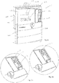
- FIG. 1 shows a smart electronic electricity meter 100 adapted for retrofitting of an external antenna and associated antenna isolation.
- the electricity meter includes a casing comprises a casing base 101, a casing cover 102 and a terminal cover 300.
- the casing base and casing cover together constitute a meter housing 200 wherein the electronic parts of the meter, such as the measurement circuit, the communication module and radio circuit, are enclosed. Additional elements such as breakers for disconnecting the consumption site, input terminals for sub meters, etc. may also be arranged inside the meter housing. Terminals for connection of power lines to the meter are arranged underneath the terminal cover.
- the terminal cover 300 is mounted on the meter housing 200 to create a complete meter casing 100.
- the terminal cover shields the terminals 201 and other interfaces from unauthorized access to avoid risk of unintended contact to the terminals and fraudulent modifications of the installation.
- the casing cover 102 is made from polymer and provided with an interfacing surface suitable for ultrasonic welding to the casing base 101.
- the casing cover has a display opening 209, an infrared communication port opening 211 and light emission openings 210 which all may be covered by a light transparent element (not shown).
- Holes for buttons are provided to enable user interaction with the meter inside the meter casing.
- Further holes for various connectors are provided in the casing cover, such as a RJ45 connector 213, input terminals and an external antenna connection 10. Some connectors are covered by various covers or lids after installation, while others are directly accessible.
- Finally holes for operating the terminals are provided to connect the meter to the power lines of the utility distribution network and the consumption site.
- the external antenna connection 10 comprising an antenna isolation board 11 inserted into a slot 214 provided in the casing cover 102.
- the antenna isolation board is connected to the main board 400 of the electricity meter as shown in Fig. 4 .
- the form factor of the slot prevents unauthorised or unintentional access to the main board, which could result in meter damage or danger due to the main board being subject to grid voltage.
- the slot is designed as a narrow passage allowing only a narrow object such as the antenna to be inserted.
- the antenna connection including the antennas isolation board 11 and antenna cable 12, is arranged in an indentation of the casing cover. Thereby, after installation the antenna connection may be cover by a lid (not shown) mounted on the casing cover.
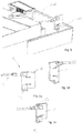
- Fig. 3a and 3b also illustrates the slot in the meter casing with and without the antenna connection.
- a connector 401 such as a plug or socket, provided on the main board.
- the slot provides a sleeve for receiving the antenna isolation board and an access opening to the main board 400.
- the slot may be arranged in the casing cover or in the casing base or another part of the casing provided that the slot provides an opening towards the main board and the opening communicates with the connector on the main board 401. In this way the slot provides access to the connector on the main board to enable the antenna isolation board to engage with the main board in that the connector on the main board and the main board connector on the antenna isolation board are connected when the antenna isolation board is inserted to the slot.
- the antenna connection comprises the antenna isolation board and an antenna cable 12.
- the antenna cable is shown to be connected to the board via a coaxial connector 13, however various other antenna connectors may also be used.
- the antenna cable may be disconnected from the isolation board or mounted to the isolation board after installation of the external antenna and antenna cable. Removing the antenna cable from the isolation board may be advantageous if the cable must be taken through narrow openings or installation holes during installation of the external antenna.
- the antenna cable may also be directly connected to the antenna isolation board.
- the antenna connection further comprises a connector 14 for engaging the connector 401 on the main board.
- the main board connector 14 is mounted on the antenna isolation board and arranged to engage with the connector 401 mounted on the main board, when the isolation board is inserted into the slot in the casing cover. Engaging the main board connector and the connector on the main board does not require manipulation of the connector or any form of contact with the connectors. The main board connector and the connector on the main board engages automatically when the isolation board is inserted to the slot.
- Connectors not requiring the use of tools or fingers for engaging are in example a MCX connector or a general connector such as a pin header.
- the antenna isolation board is a multilayered printed circuit board (PCB).
- PCB printed circuit board
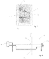
- an isolation circuit 15 is implemented as show in fig. 7 and illustrated by the diagram in Fig. 8 .
- the isolation circuit serves to provide an antenna signal path and galvanically isolate the connector 14 for engaging the main board and the connector 13 for being coupled to antenna cable.
- the main galvanic isolation is achieved by the isolation circuit including two plate capacitors 16 in the antenna signal path.
- the plate capacitors are implemented using layers of the isolation board.
- the isolation board is a six layer PCB and the plate capacitors are implemented using the inner layers 2 thru 5.
- the outer layers are not used for the plate capacitors isolate plate capacitor and protect users during installation of the external antenna.
- the laminate material of the PCB includes 35%-50% resin, such as approximately 45% resin and the laminate material has an electrical strength of 25-35 kV/mm, such as 30 kV/mm. Further, the layer thickness of the dielectric material of the PCB is chosen to be from 0.20-0.24 mm, such as 0.22 mm, whereby a sufficient electrical strength of the material may be achieved, and present insulation standards may be fulfilled.
- Fig. 7 the isolation board is shown to include a straight coaxial connector however an angled connector may also be used as shown in the remaining figures.
- the dotted line 17 in Fig. 8 illustrates the galvanic isolation barrier between the connector 14 for engaging the main board and the connector 13 for being coupled to antenna cable.
- the part of the circuit to the left of the isolation barrier is connected to the hazardous mains potential of the main board.
- the other half to the right of the isolation barrier is connected to the antenna cable and galvanically isolated.
Landscapes
- Physics & Mathematics (AREA)
- General Physics & Mathematics (AREA)
- Engineering & Computer Science (AREA)
- Power Engineering (AREA)
- Waveguide Aerials (AREA)
- Arrangements For Transmission Of Measured Signals (AREA)
Claims (10)
- Elektrizitätszähler, der zum Nachrüsten einer externen Antenne und zugehöriger Antennenisolierung angepasst ist, umfassend:- eine Messschaltung;- eine Funkschaltung, die mit einer oder mehreren Phasen verbunden ist, wodurch sie Gitterspannung ausgesetzt ist;- einen Steckverbinder (401) an einer Hauptplatine zum Herstellen einer Verbindung mit einer externen Antenne;- ein Zählergehäuse, da so angeordnet ist, dass es die Messschaltung und die Funkschaltung umschließt; und- einen Antennenisolationsplatte (11), die dazu angeordnet ist, mit der Hauptplatine (400) verbunden zu sein,wobei die Antennenisolationsplatte Folgendes umfasst:- einen Hauptplatinensteckverbinder (14) zum Herstellen der Verbindung mit dem Steckverbinder (401) an der Hauptplatine;- einen Antennensteckverbinder (13) zum Verbinden der Antennenisolationsplatte mit einem Antennenkabel; und- eine Isolationsschaltung, die einen Antennensignalweg und eine galvanische Isolationsbarriere zwischen dem Hauptplatinensteckverbinder (14) und dem Antennensteckverbinder (13) bereitstellt,dadurch gekennzeichnet, dass:- das Zählergehäuse einen Steckplatz (214) umfasst, der dazu angeordnet ist, ein Nachrüsten der Antennenisolationsplatte zu ermöglichen;- der Steckplatz in Richtung der Hauptplatine des Elektrizitätszählers offen ist; und- der Hauptplatinensteckverbinder (14) an der Antennenisolationsplatte (11) dazu angeordnet ist, eine Verbindung mit dem Steckverbinder (401) an der Hauptplatine herzustellen, wenn die Antennenisolationsplatte in den Steckplatz (214) eingesetzt ist.
- Elektrizitätszähler nach Anspruch 1, wobei der Steckplatz einen Formfaktor aufweist, der unbeabsichtigten Zugriff auf die Hauptplatine verhindert.
- Elektrizitätszähler nach einem der vorhergehenden Ansprüche, wobei der Steckplatz (214) ein schmaler Durchgang ist, der es nur einem schmalen Objekt wie etwa der Antennenisolationsplatte (11) ermöglicht eingesetzt zu werden.
- Elektrizitätszähler nach einem der vorhergehenden Ansprüche, wobei der Steckplatz (214) eine Hülle zum Aufnehmen der Antennenisolationsplatte (11) und eine Zugriffsöffnung zu der Hauptplatine (400), die so angeordnet ist, dass es dem Hauptplatinensteckverbinder (14) an der Antennenisolationsplatte (11) ermöglicht wird, eine Verbindung mit dem Steckverbinder (401) an der Hauptplatine herzustellen, bereitstellt.
- Elektrizitätszähler nach einem der vorhergehenden Ansprüche, wobei der Steckplatz (214) einen offenen Teil am Steckplatzboden aufweist, der mit dem Steckverbinder (401) an der Hauptplatine korrespondiert.
- Elektrizitätszähler nach einem der vorhergehenden Ansprüche, wobei das Antennenkabel über einen koaxialen Steckverbinder mit der Antennenisolationsplatte verbunden ist.
- Elektrizitätszähler nach einem der vorhergehenden Ansprüche, wobei das Antennenkabel direkt mit der Antennenisolationsplatte verbunden ist.
- Elektrizitätszähler nach einem der vorhergehenden Ansprüche, wobei die Antennenisolationsplatte eine mehrschichtige Leiterplatte ist und die Isolationsschaltung zwei Plattenkondensatoren beinhaltet, die unter Verwendung von Schichten der Antennenisolationsplatte umgesetzt sind.
- Elektrizitätszähler nach Anspruch 5, wobei die zwei Plattenkondensatoren unter Verwendung von inneren Schichten der Antennenisolationsplatte umgesetzt sind.
- Elektrizitätszähler nach einem der vorhergehenden Ansprüche, wobei der Steckplatz in der Umhüllungsabdeckung angeordnet ist.
Applications Claiming Priority (1)
| Application Number | Priority Date | Filing Date | Title |
|---|---|---|---|
| EP18204895 | 2018-11-07 |
Publications (2)
| Publication Number | Publication Date |
|---|---|
| EP3650870A1 EP3650870A1 (de) | 2020-05-13 |
| EP3650870B1 true EP3650870B1 (de) | 2021-09-22 |
Family
ID=67436893
Family Applications (1)
| Application Number | Title | Priority Date | Filing Date |
|---|---|---|---|
| EP19206937.5A Active EP3650870B1 (de) | 2018-11-07 | 2019-11-04 | Elektrizitätszähler mit antennenisolationsplatte |
Country Status (2)
| Country | Link |
|---|---|
| EP (1) | EP3650870B1 (de) |
| DK (1) | DK3650870T3 (de) |
Families Citing this family (1)
| Publication number | Priority date | Publication date | Assignee | Title |
|---|---|---|---|---|
| US12300872B2 (en) | 2022-03-15 | 2025-05-13 | Honeywell International Inc. | Signal boosting antenna-isolation adapter |
Family Cites Families (4)
| Publication number | Priority date | Publication date | Assignee | Title |
|---|---|---|---|---|
| US8305233B2 (en) * | 2010-01-19 | 2012-11-06 | Elster Solutions, Llc | Planar distributed element antenna isolation board |
| CN202694552U (zh) * | 2012-07-17 | 2013-01-23 | 深圳市信道科技有限公司 | 用于无线抄表装置的无线通信模块 |
| US9466870B2 (en) * | 2014-03-31 | 2016-10-11 | Elster Solutions, Llc | Electricity meter antenna configuration |
| EP3579335B1 (de) * | 2017-01-31 | 2023-05-10 | Panasonic Intellectual Property Management Co., Ltd. | Drahtloskommunikationsvorrichtung |
-
2019
- 2019-11-04 EP EP19206937.5A patent/EP3650870B1/de active Active
- 2019-11-04 DK DK19206937.5T patent/DK3650870T3/da active
Also Published As
| Publication number | Publication date |
|---|---|
| EP3650870A1 (de) | 2020-05-13 |
| DK3650870T3 (da) | 2021-12-20 |
Similar Documents
| Publication | Publication Date | Title |
|---|---|---|
| US11557868B2 (en) | Power distribution unit system incorporating smart cables and adapters | |
| CN101553959A (zh) | 电源板条系统 | |
| EP2724433B1 (de) | Elektrisches modul mit einer geerdeten schutzschaltertafel und erdungsverfahren dafür | |
| CN114636847B (zh) | 智能电表外壳 | |
| EP3650870A1 (de) | Elektrizitätszähler mit antennenisolationsplatte | |
| EP2494368B1 (de) | Zähler und kommunikationsgerät | |
| CN105203813B (zh) | 电气插拔式计量设备 | |
| JP3221005U (ja) | 電源プラグの接地構造 | |
| CN102738669B (zh) | 连接器插座 | |
| EP3086425B1 (de) | Elektrische anordnung zum oberflächeneinbau in einer wand | |
| JP5276650B2 (ja) | 電力測定器 | |
| CN209389343U (zh) | 用电隐患感知插座 | |
| CN104426086A (zh) | 直流验电接地设备及其工作方法 | |
| CN219321780U (zh) | 排插 | |
| CN101238377B (zh) | 电度表的功能单元 | |
| CN209963818U (zh) | 基于分体式电路板的充电站 | |
| CN220710776U (zh) | 一种插线板 | |
| CN109638572A (zh) | 用电隐患感知插座 | |
| CN201797678U (zh) | 通信用多频集成化直放站机箱 | |
| CN202026539U (zh) | 安全电子组装结构 | |
| CN110488061B (zh) | 一种端钮盒及电表 | |
| CN202005120U (zh) | 电子屏蔽箱 | |
| AU2010246901B2 (en) | Meter and communications apparatus | |
| CN202026541U (zh) | 防干扰安全电器盒 | |
| CN201904512U (zh) | 具有开关功能的网络连接器 |
Legal Events
| Date | Code | Title | Description |
|---|---|---|---|
| PUAI | Public reference made under article 153(3) epc to a published international application that has entered the european phase |
Free format text: ORIGINAL CODE: 0009012 |
|
| STAA | Information on the status of an ep patent application or granted ep patent |
Free format text: STATUS: THE APPLICATION HAS BEEN PUBLISHED |
|
| AK | Designated contracting states |
Kind code of ref document: A1 Designated state(s): AL AT BE BG CH CY CZ DE DK EE ES FI FR GB GR HR HU IE IS IT LI LT LU LV MC MK MT NL NO PL PT RO RS SE SI SK SM TR |
|
| AX | Request for extension of the european patent |
Extension state: BA ME |
|
| STAA | Information on the status of an ep patent application or granted ep patent |
Free format text: STATUS: REQUEST FOR EXAMINATION WAS MADE |
|
| 17P | Request for examination filed |
Effective date: 20201110 |
|
| RBV | Designated contracting states (corrected) |
Designated state(s): AL AT BE BG CH CY CZ DE DK EE ES FI FR GB GR HR HU IE IS IT LI LT LU LV MC MK MT NL NO PL PT RO RS SE SI SK SM TR |
|
| GRAP | Despatch of communication of intention to grant a patent |
Free format text: ORIGINAL CODE: EPIDOSNIGR1 |
|
| STAA | Information on the status of an ep patent application or granted ep patent |
Free format text: STATUS: GRANT OF PATENT IS INTENDED |
|
| INTG | Intention to grant announced |
Effective date: 20210416 |
|
| GRAS | Grant fee paid |
Free format text: ORIGINAL CODE: EPIDOSNIGR3 |
|
| GRAA | (expected) grant |
Free format text: ORIGINAL CODE: 0009210 |
|
| STAA | Information on the status of an ep patent application or granted ep patent |
Free format text: STATUS: THE PATENT HAS BEEN GRANTED |
|
| AK | Designated contracting states |
Kind code of ref document: B1 Designated state(s): AL AT BE BG CH CY CZ DE DK EE ES FI FR GB GR HR HU IE IS IT LI LT LU LV MC MK MT NL NO PL PT RO RS SE SI SK SM TR |
|
| REG | Reference to a national code |
Ref country code: GB Ref legal event code: FG4D |
|
| REG | Reference to a national code |
Ref country code: IE Ref legal event code: FG4D |
|
| REG | Reference to a national code |
Ref country code: DE Ref legal event code: R096 Ref document number: 602019007831 Country of ref document: DE |
|
| REG | Reference to a national code |
Ref country code: CH Ref legal event code: EP Ref country code: AT Ref legal event code: REF Ref document number: 1432735 Country of ref document: AT Kind code of ref document: T Effective date: 20211015 |
|
| REG | Reference to a national code |
Ref country code: FI Ref legal event code: FGE |
|
| REG | Reference to a national code |
Ref country code: DK Ref legal event code: T3 Effective date: 20211216 Ref country code: NO Ref legal event code: T2 Effective date: 20210922 |
|
| REG | Reference to a national code |
Ref country code: SE Ref legal event code: TRGR |
|
| REG | Reference to a national code |
Ref country code: LT Ref legal event code: MG9D |
|
| REG | Reference to a national code |
Ref country code: NL Ref legal event code: MP Effective date: 20210922 |
|
| PG25 | Lapsed in a contracting state [announced via postgrant information from national office to epo] |
Ref country code: RS Free format text: LAPSE BECAUSE OF FAILURE TO SUBMIT A TRANSLATION OF THE DESCRIPTION OR TO PAY THE FEE WITHIN THE PRESCRIBED TIME-LIMIT Effective date: 20210922 Ref country code: BG Free format text: LAPSE BECAUSE OF FAILURE TO SUBMIT A TRANSLATION OF THE DESCRIPTION OR TO PAY THE FEE WITHIN THE PRESCRIBED TIME-LIMIT Effective date: 20211222 Ref country code: LT Free format text: LAPSE BECAUSE OF FAILURE TO SUBMIT A TRANSLATION OF THE DESCRIPTION OR TO PAY THE FEE WITHIN THE PRESCRIBED TIME-LIMIT Effective date: 20210922 Ref country code: HR Free format text: LAPSE BECAUSE OF FAILURE TO SUBMIT A TRANSLATION OF THE DESCRIPTION OR TO PAY THE FEE WITHIN THE PRESCRIBED TIME-LIMIT Effective date: 20210922 |
|
| REG | Reference to a national code |
Ref country code: AT Ref legal event code: MK05 Ref document number: 1432735 Country of ref document: AT Kind code of ref document: T Effective date: 20210922 |
|
| PG25 | Lapsed in a contracting state [announced via postgrant information from national office to epo] |
Ref country code: LV Free format text: LAPSE BECAUSE OF FAILURE TO SUBMIT A TRANSLATION OF THE DESCRIPTION OR TO PAY THE FEE WITHIN THE PRESCRIBED TIME-LIMIT Effective date: 20210922 Ref country code: GR Free format text: LAPSE BECAUSE OF FAILURE TO SUBMIT A TRANSLATION OF THE DESCRIPTION OR TO PAY THE FEE WITHIN THE PRESCRIBED TIME-LIMIT Effective date: 20211223 |
|
| PG25 | Lapsed in a contracting state [announced via postgrant information from national office to epo] |
Ref country code: AT Free format text: LAPSE BECAUSE OF FAILURE TO SUBMIT A TRANSLATION OF THE DESCRIPTION OR TO PAY THE FEE WITHIN THE PRESCRIBED TIME-LIMIT Effective date: 20210922 |
|
| PG25 | Lapsed in a contracting state [announced via postgrant information from national office to epo] |
Ref country code: IS Free format text: LAPSE BECAUSE OF FAILURE TO SUBMIT A TRANSLATION OF THE DESCRIPTION OR TO PAY THE FEE WITHIN THE PRESCRIBED TIME-LIMIT Effective date: 20220122 Ref country code: SK Free format text: LAPSE BECAUSE OF FAILURE TO SUBMIT A TRANSLATION OF THE DESCRIPTION OR TO PAY THE FEE WITHIN THE PRESCRIBED TIME-LIMIT Effective date: 20210922 Ref country code: RO Free format text: LAPSE BECAUSE OF FAILURE TO SUBMIT A TRANSLATION OF THE DESCRIPTION OR TO PAY THE FEE WITHIN THE PRESCRIBED TIME-LIMIT Effective date: 20210922 Ref country code: PT Free format text: LAPSE BECAUSE OF FAILURE TO SUBMIT A TRANSLATION OF THE DESCRIPTION OR TO PAY THE FEE WITHIN THE PRESCRIBED TIME-LIMIT Effective date: 20220124 Ref country code: PL Free format text: LAPSE BECAUSE OF FAILURE TO SUBMIT A TRANSLATION OF THE DESCRIPTION OR TO PAY THE FEE WITHIN THE PRESCRIBED TIME-LIMIT Effective date: 20210922 Ref country code: NL Free format text: LAPSE BECAUSE OF FAILURE TO SUBMIT A TRANSLATION OF THE DESCRIPTION OR TO PAY THE FEE WITHIN THE PRESCRIBED TIME-LIMIT Effective date: 20210922 Ref country code: ES Free format text: LAPSE BECAUSE OF FAILURE TO SUBMIT A TRANSLATION OF THE DESCRIPTION OR TO PAY THE FEE WITHIN THE PRESCRIBED TIME-LIMIT Effective date: 20210922 Ref country code: EE Free format text: LAPSE BECAUSE OF FAILURE TO SUBMIT A TRANSLATION OF THE DESCRIPTION OR TO PAY THE FEE WITHIN THE PRESCRIBED TIME-LIMIT Effective date: 20210922 Ref country code: CZ Free format text: LAPSE BECAUSE OF FAILURE TO SUBMIT A TRANSLATION OF THE DESCRIPTION OR TO PAY THE FEE WITHIN THE PRESCRIBED TIME-LIMIT Effective date: 20210922 Ref country code: AL Free format text: LAPSE BECAUSE OF FAILURE TO SUBMIT A TRANSLATION OF THE DESCRIPTION OR TO PAY THE FEE WITHIN THE PRESCRIBED TIME-LIMIT Effective date: 20210922 |
|
| REG | Reference to a national code |
Ref country code: DE Ref legal event code: R097 Ref document number: 602019007831 Country of ref document: DE |
|
| PG25 | Lapsed in a contracting state [announced via postgrant information from national office to epo] |
Ref country code: MC Free format text: LAPSE BECAUSE OF FAILURE TO SUBMIT A TRANSLATION OF THE DESCRIPTION OR TO PAY THE FEE WITHIN THE PRESCRIBED TIME-LIMIT Effective date: 20210922 |
|
| PG25 | Lapsed in a contracting state [announced via postgrant information from national office to epo] |
Ref country code: LU Free format text: LAPSE BECAUSE OF NON-PAYMENT OF DUE FEES Effective date: 20211104 Ref country code: BE Free format text: LAPSE BECAUSE OF NON-PAYMENT OF DUE FEES Effective date: 20211130 |
|
| PLBE | No opposition filed within time limit |
Free format text: ORIGINAL CODE: 0009261 |
|
| STAA | Information on the status of an ep patent application or granted ep patent |
Free format text: STATUS: NO OPPOSITION FILED WITHIN TIME LIMIT |
|
| REG | Reference to a national code |
Ref country code: BE Ref legal event code: MM Effective date: 20211130 |
|
| 26N | No opposition filed |
Effective date: 20220623 |
|
| PG25 | Lapsed in a contracting state [announced via postgrant information from national office to epo] |
Ref country code: SI Free format text: LAPSE BECAUSE OF FAILURE TO SUBMIT A TRANSLATION OF THE DESCRIPTION OR TO PAY THE FEE WITHIN THE PRESCRIBED TIME-LIMIT Effective date: 20210922 |
|
| PG25 | Lapsed in a contracting state [announced via postgrant information from national office to epo] |
Ref country code: IT Free format text: LAPSE BECAUSE OF FAILURE TO SUBMIT A TRANSLATION OF THE DESCRIPTION OR TO PAY THE FEE WITHIN THE PRESCRIBED TIME-LIMIT Effective date: 20210922 |
|
| P01 | Opt-out of the competence of the unified patent court (upc) registered |
Effective date: 20230518 |
|
| PG25 | Lapsed in a contracting state [announced via postgrant information from national office to epo] |
Ref country code: CY Free format text: LAPSE BECAUSE OF FAILURE TO SUBMIT A TRANSLATION OF THE DESCRIPTION OR TO PAY THE FEE WITHIN THE PRESCRIBED TIME-LIMIT Effective date: 20210922 |
|
| PG25 | Lapsed in a contracting state [announced via postgrant information from national office to epo] |
Ref country code: SM Free format text: LAPSE BECAUSE OF FAILURE TO SUBMIT A TRANSLATION OF THE DESCRIPTION OR TO PAY THE FEE WITHIN THE PRESCRIBED TIME-LIMIT Effective date: 20210922 Ref country code: HU Free format text: LAPSE BECAUSE OF FAILURE TO SUBMIT A TRANSLATION OF THE DESCRIPTION OR TO PAY THE FEE WITHIN THE PRESCRIBED TIME-LIMIT; INVALID AB INITIO Effective date: 20191104 |
|
| PG25 | Lapsed in a contracting state [announced via postgrant information from national office to epo] |
Ref country code: MK Free format text: LAPSE BECAUSE OF FAILURE TO SUBMIT A TRANSLATION OF THE DESCRIPTION OR TO PAY THE FEE WITHIN THE PRESCRIBED TIME-LIMIT Effective date: 20210922 |
|
| PG25 | Lapsed in a contracting state [announced via postgrant information from national office to epo] |
Ref country code: TR Free format text: LAPSE BECAUSE OF FAILURE TO SUBMIT A TRANSLATION OF THE DESCRIPTION OR TO PAY THE FEE WITHIN THE PRESCRIBED TIME-LIMIT Effective date: 20210922 |
|
| GBPC | Gb: european patent ceased through non-payment of renewal fee |
Effective date: 20231104 |
|
| PG25 | Lapsed in a contracting state [announced via postgrant information from national office to epo] |
Ref country code: MT Free format text: LAPSE BECAUSE OF FAILURE TO SUBMIT A TRANSLATION OF THE DESCRIPTION OR TO PAY THE FEE WITHIN THE PRESCRIBED TIME-LIMIT Effective date: 20210922 |
|
| PG25 | Lapsed in a contracting state [announced via postgrant information from national office to epo] |
Ref country code: GB Free format text: LAPSE BECAUSE OF NON-PAYMENT OF DUE FEES Effective date: 20231104 |
|
| PG25 | Lapsed in a contracting state [announced via postgrant information from national office to epo] |
Ref country code: GB Free format text: LAPSE BECAUSE OF NON-PAYMENT OF DUE FEES Effective date: 20231104 |
|
| REG | Reference to a national code |
Ref country code: CH Ref legal event code: U11 Free format text: ST27 STATUS EVENT CODE: U-0-0-U10-U11 (AS PROVIDED BY THE NATIONAL OFFICE) Effective date: 20251201 |
|
| PGFP | Annual fee paid to national office [announced via postgrant information from national office to epo] |
Ref country code: DE Payment date: 20251119 Year of fee payment: 7 |
|
| PGFP | Annual fee paid to national office [announced via postgrant information from national office to epo] |
Ref country code: NO Payment date: 20251125 Year of fee payment: 7 |
|
| PGFP | Annual fee paid to national office [announced via postgrant information from national office to epo] |
Ref country code: FI Payment date: 20251125 Year of fee payment: 7 Ref country code: DK Payment date: 20251125 Year of fee payment: 7 |
|
| PGFP | Annual fee paid to national office [announced via postgrant information from national office to epo] |
Ref country code: FR Payment date: 20251126 Year of fee payment: 7 |
|
| PGFP | Annual fee paid to national office [announced via postgrant information from national office to epo] |
Ref country code: CH Payment date: 20251201 Year of fee payment: 7 Ref country code: SE Payment date: 20251119 Year of fee payment: 7 |
|
| PGFP | Annual fee paid to national office [announced via postgrant information from national office to epo] |
Ref country code: IE Payment date: 20251121 Year of fee payment: 7 |