EP3650851B1 - Calibration of an air quality sensor in a device - Google Patents
Calibration of an air quality sensor in a device Download PDFInfo
- Publication number
- EP3650851B1 EP3650851B1 EP18306451.8A EP18306451A EP3650851B1 EP 3650851 B1 EP3650851 B1 EP 3650851B1 EP 18306451 A EP18306451 A EP 18306451A EP 3650851 B1 EP3650851 B1 EP 3650851B1
- Authority
- EP
- European Patent Office
- Prior art keywords
- cavity
- air
- quality sensor
- air quality
- internal volume
- Prior art date
- Legal status (The legal status is an assumption and is not a legal conclusion. Google has not performed a legal analysis and makes no representation as to the accuracy of the status listed.)
- Active
Links
Images




Classifications
-
- G—PHYSICS
- G01—MEASURING; TESTING
- G01N—INVESTIGATING OR ANALYSING MATERIALS BY DETERMINING THEIR CHEMICAL OR PHYSICAL PROPERTIES
- G01N33/00—Investigating or analysing materials by specific methods not covered by groups G01N1/00 - G01N31/00
- G01N33/0004—Gaseous mixtures, e.g. polluted air
- G01N33/0006—Calibrating gas analysers
-
- A—HUMAN NECESSITIES
- A61—MEDICAL OR VETERINARY SCIENCE; HYGIENE
- A61B—DIAGNOSIS; SURGERY; IDENTIFICATION
- A61B5/00—Measuring for diagnostic purposes; Identification of persons
- A61B5/02—Detecting, measuring or recording for evaluating the cardiovascular system, e.g. pulse, heart rate, blood pressure or blood flow
- A61B5/0205—Simultaneously evaluating both cardiovascular conditions and different types of body conditions, e.g. heart and respiratory condition
-
- A—HUMAN NECESSITIES
- A61—MEDICAL OR VETERINARY SCIENCE; HYGIENE
- A61B—DIAGNOSIS; SURGERY; IDENTIFICATION
- A61B5/00—Measuring for diagnostic purposes; Identification of persons
- A61B5/103—Measuring devices for testing the shape, pattern, colour, size or movement of the body or parts thereof, for diagnostic purposes
- A61B5/11—Measuring movement of the entire body or parts thereof, e.g. head or hand tremor or mobility of a limb
- A61B5/1118—Determining activity level
-
- A—HUMAN NECESSITIES
- A61—MEDICAL OR VETERINARY SCIENCE; HYGIENE
- A61B—DIAGNOSIS; SURGERY; IDENTIFICATION
- A61B5/00—Measuring for diagnostic purposes; Identification of persons
- A61B5/68—Arrangements of detecting, measuring or recording means, e.g. sensors, in relation to patient
- A61B5/6801—Arrangements of detecting, measuring or recording means, e.g. sensors, in relation to patient specially adapted to be attached to or worn on the body surface
- A61B5/6802—Sensor mounted on worn items
- A61B5/681—Wristwatch-type devices
-
- G—PHYSICS
- G01—MEASURING; TESTING
- G01N—INVESTIGATING OR ANALYSING MATERIALS BY DETERMINING THEIR CHEMICAL OR PHYSICAL PROPERTIES
- G01N33/00—Investigating or analysing materials by specific methods not covered by groups G01N1/00 - G01N31/00
- G01N33/0004—Gaseous mixtures, e.g. polluted air
- G01N33/0009—General constructional details of gas analysers, e.g. portable test equipment
- G01N33/0027—General constructional details of gas analysers, e.g. portable test equipment concerning the detector
- G01N33/0036—General constructional details of gas analysers, e.g. portable test equipment concerning the detector specially adapted to detect a particular component
- G01N33/0037—NOx
-
- G—PHYSICS
- G04—HOROLOGY
- G04G—ELECTRONIC TIME-PIECES
- G04G21/00—Input or output devices integrated in time-pieces
- G04G21/02—Detectors of external physical values, e.g. temperature
-
- G—PHYSICS
- G04—HOROLOGY
- G04G—ELECTRONIC TIME-PIECES
- G04G21/00—Input or output devices integrated in time-pieces
- G04G21/02—Detectors of external physical values, e.g. temperature
- G04G21/025—Detectors of external physical values, e.g. temperature for measuring physiological data
-
- A—HUMAN NECESSITIES
- A61—MEDICAL OR VETERINARY SCIENCE; HYGIENE
- A61B—DIAGNOSIS; SURGERY; IDENTIFICATION
- A61B2560/00—Constructional details of operational features of apparatus; Accessories for medical measuring apparatus
- A61B2560/02—Operational features
- A61B2560/0223—Operational features of calibration, e.g. protocols for calibrating sensors
-
- A—HUMAN NECESSITIES
- A61—MEDICAL OR VETERINARY SCIENCE; HYGIENE
- A61B—DIAGNOSIS; SURGERY; IDENTIFICATION
- A61B2560/00—Constructional details of operational features of apparatus; Accessories for medical measuring apparatus
- A61B2560/02—Operational features
- A61B2560/0242—Operational features adapted to measure environmental factors, e.g. temperature, pollution
-
- Y—GENERAL TAGGING OF NEW TECHNOLOGICAL DEVELOPMENTS; GENERAL TAGGING OF CROSS-SECTIONAL TECHNOLOGIES SPANNING OVER SEVERAL SECTIONS OF THE IPC; TECHNICAL SUBJECTS COVERED BY FORMER USPC CROSS-REFERENCE ART COLLECTIONS [XRACs] AND DIGESTS
- Y02—TECHNOLOGIES OR APPLICATIONS FOR MITIGATION OR ADAPTATION AGAINST CLIMATE CHANGE
- Y02A—TECHNOLOGIES FOR ADAPTATION TO CLIMATE CHANGE
- Y02A50/00—TECHNOLOGIES FOR ADAPTATION TO CLIMATE CHANGE in human health protection, e.g. against extreme weather
- Y02A50/20—Air quality improvement or preservation, e.g. vehicle emission control or emission reduction by using catalytic converters
Definitions
- the present disclosure concerns a wearable device, for example a wrist watch or an activity tracker, with an air quality sensor.
- the air quality sensor can detect and monitor the presence of air pollution in a surrounding area, for both indoor and outdoor environments. It can provide useful information to a user on the air quality that may negatively impact his health, and cause harmful effects such as cold symptoms or respiratory diseases.
- the air quality sensor can produce an electric current according to a concentration level of some compounds present in the air.
- the electrical current may also vary according to other parameters, such as humidity, temperature and aging of other components constitutive of the device which may release gas affecting the accuracy of the air quality sensor located nearby.
- Calibration of gas sensors is generally known, for example from WO 2017/207594 A1 , US 6774613 B1 , US 2011/197649 A1 , or US 4590789 A .
- the present disclosure relates to a device comprising a cavity defining an internal volume, an air quality sensor being adapted to measure a concentration of at least one air compound present in the internal volume.
- the cavity can be alternatively in:
- Figure 1 shows a device 1 according to the present disclosure.
- the device 1 is a wearable device, such as a watch, a wrist watch or an activity tracker.
- the device 1 can also be any other wearable device, such as glasses, a necklace, a ring, etc.
- the device 1 may comprise a casing 2, a dial plate 3a and a top cover 3b of the dial plate 3a.
- the casing 2, the dial plate 3a and the top cover 3b are arranged one on top of another in a vertical direction Z.
- the thickness of the device 1 is thus defined along this vertical direction Z.
- the device 1 can be a digital watch, such that the dial plate 3a comprises a display 31.
- the device 1 may be an analog type watch, such that the dial plate 3a comprises stick-like hands 32 with a traditional clock face for instance.
- the casing 2 may comprise projections 21 for attachment to a wristband (not illustrated) as known per se and thus not described in more details.
- the device 1 can have a round shape. However, other shapes, such as square or rectangle, are also possible. Similarly, the device 1 can be relatively small, as for a watch for example, or can have bigger dimensions when it comes to objects having larger dimensions, as for a weight scale for another example.
- the device 1 also comprises an internal part 4 illustrated on figure 2 . As illustrated on figure 1 , the internal part 4 can be sandwiched between the casing 2 and the dial plate 3a.
- the internal part 4 comprises a cavity 5.
- the cavity 5 may be molded, in particular as a single piece.
- the cavity 5 comprises a wall 51 and an opening 52.
- the wall 51 forms at least the lateral portion of the cavity 5.
- the cavity 5 also comprises a bottom portion 53 and a top portion 54.
- the bottom portion 53 can comprise a first hole 55 and a second hole 56. As illustrated on figures 4 and 9 , the holes 55, 56 can have a circular shape.
- the top portion 54 can be closed by a cover 6.
- the cavity 5 defines and delimits an internal volume.
- the internal volume is suited and intended to receive an air volume coming from the outside of the cavity 5, and more precisely from the outside of the device 1, through the opening 52.
- the cavity 5 may take any form, notably cylindrical, parallelepipedal or other so as to form the internal volume.
- the cavity 5 can be arranged on, or fixed to, a printed circuit board 7.
- the printed circuit board 7 can comprise a control unit, an oscillator, a battery either conventional or rechargeable (not illustrated), or any known elements for the functioning of the device 1.
- the casing 2 can comprise a perforated area 22, wherein through bores 23 opens on the cavity 5 and the outside of the device 1.
- the through bores 23 may be aligned in the perforated area 22, facing the opening 52 of the cavity 5.
- the casing 2 comprises six through bores 23.
- Each through bore 23 may have a diameter comprised between 0.5 mm (millimeter) and 1.5 mm, for example about 1 mm.
- the device 1 can also comprise a membrane 8 which is impermeable to water but permeable to air.
- the water-impermeable membrane 8 is placed facing the opening 52 so that air entering the cavity 5 passes through the membrane 8.
- the water-impermeable membrane 8 can be placed in front of the opening 52 toward the outside of the cavity 5.
- the water-impermeable membrane 8 may as well be inside the cavity 5 on the inside face of the opening 52.
- the water-impermeable membrane 8 may also be placed on the internal or external side of the perforated area 22. This way, the water-impermeable membrane 8 can ensure that the whole device 1 is waterproof.
- the water-impermeable membrane 8 prevents the ingress of water inside the cavity 5. This way, the user can for example immerse briefly the device 1 in water without any damage.
- the water-impermeable membrane 8 may be formed as a thin wall manufactured in synthetic material having a microporous structure.
- the device 1 comprises an air quality sensor 9.
- the air quality sensor 9 is arranged in the cavity 5 of the internal part 4.
- the air quality sensor 9 is placed in the first hole 55 of the cavity 5. This way, the air quality sensor 9 is in direct contact with the air present in the internal volume of the cavity 5.
- the air quality sensor 9 is sealed with the cavity 5 in an airtight manner with a gasket 11.
- the device 1 can comprise a supporting element 10.
- the supporting element 10 holds the air quality sensor 9 against the cavity 5.
- the cavity 5 can be fixedly attached to the supporting element 10.
- the device 1 may comprise screws 14 that go through the cavity 5 and the printed circuit board 7 and that are fixed to the supporting element 10.
- Spring elements 15 are compressed between the printed circuit board 7 and the air quality sensor 9.
- the spring elements 15 can be electrical conductors that ensure electrical contact between the air quality sensor 9 and the printed circuit board 7.
- the air quality sensor 9 may be soldered to the printed circuit board 7 and the cavity 5 may be screwed on the printed circuit board 7, thus compressing the gasket 11.
- the device 1 can also comprise other types of sensors, such as a temperature sensor, a humidity sensor, a pressure sensor, or the like.
- the device 1 comprises a humidity sensor 13 arranged in the cavity 5 of the internal part 4.
- the humidity sensor 13 is placed in the second hole 56 of the cavity 5.
- the humidity sensor 13 is sealed with the cavity 5 in an airtight manner with a gasket 12.
- the gasket 12 can seal the humidity sensor 13 with the cavity 5 in the same manner as the gasket 11 seals the air quality sensor 9 with the cavity 5.
- Air can exclusively circulate between the outside and the inside of the cavity 5 through the opening 52, the cavity 5 being elsewhere isolated from the device 1.
- the cavity 5 is isolated from the other elements of the internal part 4 of the device 1, and more precisely from the other elements of the printed circuit board 7.
- the air quality sensor 9 is adapted to measure a concentration of one or several air compounds in the vicinity of the device 1.
- “In the vicinity of the device” means that the air compound(s) measured by the device 1 are not substantially different from the air compound(s) that the user of the device 1 is breathing or that surrounds the device 1.
- the one or several air compounds are of interest.
- the device 1 is adapted to detect compounds in the general environment of the device 1 and/or detect some chemical species present in the breath of the user when the user exhales or blows toward the device 1.
- the air quality sensor 9 is particularly suited to measure a concentration of some air compounds which may have an impact on human health (also called “pollutants").
- the air quality sensor 9 may be adapted to measure a concentration of an air compound chosen among NO 2 (nitrogen dioxide), O 3 (ozone), NO (nitric oxide), CO (carbon monoxide), SO 2 (sulphur dioxide), CO 2 (carbon dioxide), H 2 S (hydrogen sulfide), CI (chlorine), benzene, CH4 (methane), NH 4 (ammonia), (CH 3 ) 2 CO (acetone) and alcohol vapours.
- the air compound can be a volatile organic compound.
- the air compound can be more precisely NH 4 (ammonia), (CH 3 ) 2 CO (acetone) and alcohol vapours.
- the air quality sensor 9 may be adapted to measure a concentration of only one air compound or of several air compounds, in particular simultaneously. For instance, the air quality sensor 9 may be adapted to measure a concentration of two air compounds, such as those mentioned-above. The air quality sensor 9 may be reactive both to NO 2 and O 3 .
- the air quality sensor 9 can be an amperometric sensor.
- the air quality sensor 9 produces an electric current when a potential is applied between electrodes.
- a first chemical occurs at least at one working electrode (or catalyst) when in contact with the air, which takes place with regard to at least one auxiliary electrode (or reference).
- Measurement of concentration of the air compound can also depend on other parameters, such as the ambient temperature, ambient humidity (more particularly measured by the humidity sensor 13 described above), ambient pressure or the electric intensity flowing through the air quality sensor 9.
- Electrolyte may be provided between two or more electrodes to transport the ions produced by the chemical reactions from one electrode to the other electrode.
- the air quality sensor 9 may have a low electric consumption, for example an average electric consumption when powered of less than 10 ⁇ A (microampere), or less than 2 ⁇ A.
- the electric current produced by the air quality sensor 9 can be comprised between 0.1 nA (nanoAmp) and 20 nA depending on the concentration of the air compound measured.
- the lifetime of the battery of the device 1 can be sufficient to ensure a sufficiently long working life of the air quality sensor 9.
- the battery of the device 1 may have a capacity of 120 mAh (milliampere hour), with an autonomy of 25 days or 600 hours without using the air quality sensor 9. Its average electric consumption is 200 ⁇ A.
- the average electric consumption of the air quality sensor 9 is equal to 5% of the average electric consumption of the device 1 without using the air quality sensor 9.
- the device 1 may thus have an autonomy of around 24 days or around 570 hours when powering the air quality sensor 9.
- the air quality sensor 9 is connected to the control unit of the device 1 which collects and processes the measurements of concentrations of the air compounds.
- the device 1 may wirelessly communicate with another external terminal (not illustrated), such as a smartphone or a server, to send the collected measurement data.
- another external terminal not illustrated
- Measurements made by the air quality sensor 9 can become out of calibration over time for a number or reasons.
- the cavity 5 can be alternatively in an open state or a closed state.
- concentration of the air compound can decrease over time, in particular since air cannot enter anymore into the cavity 5.
- the air quality sensor 9 is adapted to consume the air compound that is present in the internal volume of the cavity 5.
- the air quality sensor 9 can thus consume the entire air compound present in the internal volume of the cavity 5, so that the cavity 5 no longer comprises the air compound or comprises the air compound having a concentration that is below a predefined threshold, such as the detection threshold of the air quality device 9.
- such predefined threshold can be 5 ppb (parts per billion), 1 ppb or even 0.1 ppb.
- the air quality sensor 9 can be adapted to measure the concentration of NO 2 according to the chemical reaction mentioned above, so that the air compound NO 2 can be progressively consumed by chemical reaction by the air quality sensor 9 when the cavity 5 is in the closed state, so that no NO 2 is finally left in the internal volume of the cavity 5 or only in trace amounts.
- the air quality sensor 9 can consume the air compound in less than 8 hours, or in less than 4 hours, or in less than one hour, or even in less than 30 minutes. Consumption time of the air compound may depend on the air quality sensor parameters and on the size of the internal volume of the cavity 5.
- the internal volume of the cavity 5 can be less than 0.3 cm 3 (cubic centimetre), less than 0.2 cm 3 , less than 0.1 cm 3 , or even less than 0.05 cm 3 .
- the air quality sensor 9 can be calibrated.
- Calibration can encompass several possibilities, such as setting a new baseline measurement or the sensitivity of the air quality sensor 9. Calibration can also permit to obtain a calibration function in the form of a curve, a look-up table, or any other form in order to describe the linear or non-linear relation between the air compound concentration and the measurements to be performed by the air quality sensor 9.
- the air quality sensor 9 can set a new baseline measurement (or a new "zero"). Every new measurement of the air quality sensor 9 can then be estimated by being compared with this new baseline measurement. This ensures a good reliability and accuracy of the air quality sensor 9 over time.
- the air quality sensor 9 may be adapted to measure several air compounds but can be calibrated according to only one air compound.
- the material of the cavity 5 may also be advantageously chosen not to affect the measurements made by the air quality sensor 9.
- the cavity 5 may be made of polytetrafluoroethylene (PTFE).
- the device 1 comprises a first grid 101 and a second grid 102.
- the first grid 101 is fixed relative to the cavity 5.
- the first grid 101 may be integral with the cavity 5.
- the first grid 101 is located at the inlet of, or forms, the opening 52 of the cavity 5.
- the second grid 102 is adapted to move relative to the first grid 101 so that the cavity 5 can be in the open state or in the closed state. More precisely, the second grid 102 is adapted to slide relative to the first grid 101 along a longitudinal direction X1.
- the longitudinal direction X1 can be perpendicular to the vertical direction Z.
- the device 1 may comprise an actuator or motor (not illustrated) adapted to allow small displacements.
- the motor can for instance be piezoelectric, electromagnetic or it can be a stepper motor.
- Each of the first and second grids 101, 102 comprises a plurality of through apertures 103, 104.
- the through apertures 103, 104 of the first and second grids 101, 102 are respectively spaced apart regularly in the longitudinal direction X1.
- each of the first and second grids 101, 102 comprises fourteen through apertures 103, 104.
- the through apertures 103, 104 of the first and second grids 101, 102 can be of rectangular shapes. However, other shapes are possible.
- the through apertures 103 of the first grid 101 have a width n in the longitudinal direction X1.
- the width n of the through apertures 103 of the first grid 101 can be less than 1 mm (millimeter), or even less than 0.5 mm.
- the width n can be for instance equal to 0.3 mm.
- the through apertures 103 of the first grid 101 are spaced apart regularly from each other by a distance d (also called "pitch").
- the through apertures 104 of the second grid 102 have a width n' in the longitudinal direction X1.
- the width n' of the through apertures 104 of the second grid 102 can be less than 1 mm (millimeter), or even less than 0.5 mm.
- the width n' can be for instance equal to 0.3 millimeters.
- the through apertures 104 of the second grid 102 are spaced apart regularly from each other by a distance d'.
- the widths n, n' and the distances d, d' are interrelated so that the cavity 5 can be opened or closed in a satisfactory manner by moving the second grid 102 relative to the first grid 101
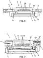
- the first and second grids 101, 102 are such that: n ′ ⁇ n , This way, in the open position, a through aperture 104 of the second grid 102 overlaps totally a though aperture 103 of the first grid 101. All or some of the though apertures 103, 104 face each other. The cavity 5 is thus open as illustrated on figure 7 .
- the first and second grids 101, 102 are such that: d ′ ⁇ n and d ⁇ n ′
- the solid space between two consecutive through apertures 104 of the second grid 102 overlaps totally, or covers, a through aperture 103 of the first grid 101.
- the solid space between two consecutive through apertures 103 of the first grid 101 overlaps totally, or covers, a through aperture 104 of the second grid 102.
- the through apertures 103, 104 of the first and second grids 101, 102 are offset to one another in the longitudinal direction X1.
- the cavity 5 is thus totally closed as illustrated on figure 6 .
- the device 1 comprises a door 105.
- the door 105 is adapted to move relative to the opening 52 so that the cavity 5 can be in the open state or in the closed state. More precisely, the door 105 is adapted to slide relative to the opening 52 along a longitudinal direction X2.
- the opening 52 may consist in a single aperture which extends in the longitudinal direction X2.
- the device 1 may comprise a toothed disk or a pinion 106.
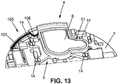
- the door 105 comprises a rack 107 that can engage with the toothed disk 106, as illustrated more particularly on figure 13 .
- the door 105 is a full solid surface, which does not comprise any through apertures unlike the second grid 102 of the first embodiment described above.
- the door 105 does not cover the opening 52 by being slidably moved, preferably totally, on a side of the opening 52 along the longitudinal direction X2.
- the cavity 5 is thus open as illustrated on figure 12 .
- the cavity 5 can switch from the open state to the closed state, it is possible to recalibrate the air quality sensor 9 when the air compound to be measured has been totally, or almost totally, consumed in the internal volume.
- This calibration is advantageously implemented when the user is unlikely to use the device 1 as well as the embedded air quality sensor 9 for a given period of time.
- the device 1 comprises an accelerometer (not illustrated) adapted to detect a movement of the user. Calibration of the air quality sensor 9 is then implemented when the accelerometer does no detect any movement of the user.
- Such calibration can for instance occur during a sleeping phase of the user or, in the embodiment wherein the device 1 is a wearable device, when the device 1 is not worn by the user.
- Such calibration can also be repeated in a periodic manner. For instance, such calibration can occur at least once a month, or at least once a week, or even at least once a day. This way, it ensures that the air quality sensor 9 always output a reliable measurement of the concentration of the air compound.
Landscapes
- Health & Medical Sciences (AREA)
- Life Sciences & Earth Sciences (AREA)
- Engineering & Computer Science (AREA)
- Physics & Mathematics (AREA)
- General Health & Medical Sciences (AREA)
- Chemical & Material Sciences (AREA)
- Pathology (AREA)
- Biophysics (AREA)
- Physiology (AREA)
- General Physics & Mathematics (AREA)
- Heart & Thoracic Surgery (AREA)
- Animal Behavior & Ethology (AREA)
- Surgery (AREA)
- Public Health (AREA)
- Veterinary Medicine (AREA)
- Molecular Biology (AREA)
- Medical Informatics (AREA)
- Biomedical Technology (AREA)
- Cardiology (AREA)
- Combustion & Propulsion (AREA)
- Food Science & Technology (AREA)
- Medicinal Chemistry (AREA)
- Analytical Chemistry (AREA)
- Biochemistry (AREA)
- Immunology (AREA)
- Oral & Maxillofacial Surgery (AREA)
- Pulmonology (AREA)
- Dentistry (AREA)
- Investigating Or Analyzing Materials By The Use Of Electric Means (AREA)
Description
- The present disclosure concerns a wearable device, for example a wrist watch or an activity tracker, with an air quality sensor.
- It is known to embed an air quality sensor into a device like a wrist watch, for example from
US 2017/351221 A1 orCN 204086834 U . - The air quality sensor can detect and monitor the presence of air pollution in a surrounding area, for both indoor and outdoor environments. It can provide useful information to a user on the air quality that may negatively impact his health, and cause harmful effects such as cold symptoms or respiratory diseases.
- In such a device, the air quality sensor can produce an electric current according to a concentration level of some compounds present in the air.
- However, the electrical current may also vary according to other parameters, such as humidity, temperature and aging of other components constitutive of the device which may release gas affecting the accuracy of the air quality sensor located nearby.
- It is therefore necessary to recalibrate the sensor on a regular basis. In the absence of recalibration, the air quality sensor is likely to output inaccurate measures that may mislead the user. Calibration of gas sensors is generally known, for example from
WO 2017/207594 A1 ,US 6774613 B1 ,US 2011/197649 A1 , orUS 4590789 A . - However, calibration process is usually difficult and burdensome to implement for a user.
- Therefore, there remains a need to provide a device with an air quality sensor able to provide reliable air quality measurements, whatever its conditions of use, and that remains easy to use in the context of everyday life.
- The present disclosure relates to a device comprising a cavity defining an internal volume, an air quality sensor being adapted to measure a concentration of at least one air compound present in the internal volume. The cavity can be alternatively in:
- an open state in which air can enter into the cavity from the outside of the cavity, and
- a closed state in which no air can circulate between the outside and the inside of the cavity,
- Thanks to these dispositions, it is possible to perform a reliable measurement of the air compound.
- In various embodiments according to the present disclosure, use may also possibly be made of one and/or the other of the following dispositions, taken separately or in combination, according to which:
- the cavity comprises an opening so that air can exclusively enter the cavity through the opening, the cavity being elsewhere isolated from the device ;
- the air quality sensor is adapted to produce an electric current by consuming the air compound present in the internal volume of the cavity,
- the air compound is NO2,
- the internal volume of the cavity is less than 0.3 cm3, less than 0.2 cm3, less than 0.1 cm3, or even less than 0.05 cm3;
- the cavity comprises a first grid and a second grid, the second grid being adapted to move relative to the first grid so that the cavity can be in the open state or in the closed state;
- each of the first and second grids comprises a plurality of through apertures, wherein at least some of the through apertures of the first and second grids face each other when the cavity is in the open state and wherein the through apertures of the first and second grids are offset to one another when the cavity is in the closed state;
- the cavity comprises a door, the door being adapted to move relative to the opening so that the cavity can be in the open state or in the closed state;
- the cavity comprises a bottom portion and a top portion, wherein the bottom portion comprises a first hole and a second hole, the air quality sensor being located in the first hole, the cavity and the air quality sensor being sealed together in an airtight manner by using at least one gasket, such that the air quality sensor is in direct contact with the air present in the internal volume of the cavity. The present disclosure also relates to a method for calibrating an air quality sensor of the device according to any of appended
claims 1 to 9, comprising at least the steps of: - switching the cavity from the open state to the closed state;
- waiting for the internal volume to no longer comprise the air compound or to comprise a concentration of the air compound that is below a predefined threshold; and
- calibrating the air quality sensor.
- Other features of the disclosure appear from the following detailed description, given by way of non-limiting example, and with reference to the accompanying drawings, in which:
-
Figure 1 shows an exploded view of the device according to the present disclosure, -
Figure 2 shows a perspective view of an internal part of the device offigure 1 according to a first embodiment, -
Figure 3 shows an exploded view of the internal part offigure 2 , -
Figure 4 shows a perspective view of a cavity of the internal part offigures 2 and 3 , the cavity comprising a first grid, -
Figure 5A shows front view of a second grid according to the first embodiment, -
Figure 5B shows a cross section of the second grid offigure 5A according to cross-sectional plane VB-VB, -
Figure 6 shows a view of the cavity offigure 3 in which the cavity is in a closed state, -
Figure 7 shows a view of the cavity offigure 3 in which the cavity is in an open state, -
Figure 8 shows an exploded view of the internal part of a device offigure 1 according to a second embodiment, -
Figure 9 shows a perspective view of a cavity of the internal part offigure 8 , -
Figure 10 shows front view of a door according to the second embodiment, -
Figure 11 shows a view of the cavity offigure 8 in which the cavity is in a closed state, -
Figure 12 shows a view of the cavity offigure 8 in which the cavity is in an open state, and -
Figure 13 shows a perspective top view of the internal part offigure 12 . - In the figures, the same references denote identical or similar elements.
-
Figure 1 shows adevice 1 according to the present disclosure. Thedevice 1 is a wearable device, such as a watch, a wrist watch or an activity tracker. - However, the
device 1 can also be any other wearable device, such as glasses, a necklace, a ring, etc. - As illustrated on
figure 1 , thedevice 1 may comprise acasing 2, adial plate 3a and atop cover 3b of thedial plate 3a. Thecasing 2, thedial plate 3a and thetop cover 3b are arranged one on top of another in a vertical direction Z. The thickness of thedevice 1 is thus defined along this vertical direction Z. - The
device 1 can be a digital watch, such that thedial plate 3a comprises adisplay 31. As a variant or complementarily, thedevice 1 may be an analog type watch, such that thedial plate 3a comprises stick-like hands 32 with a traditional clock face for instance. - To be attached to a wrist of a user, the
casing 2 may compriseprojections 21 for attachment to a wristband (not illustrated) as known per se and thus not described in more details. - As illustrated on
figure 1 , thedevice 1 can have a round shape. However, other shapes, such as square or rectangle, are also possible. Similarly, thedevice 1 can be relatively small, as for a watch for example, or can have bigger dimensions when it comes to objects having larger dimensions, as for a weight scale for another example. - The
device 1 also comprises aninternal part 4 illustrated onfigure 2 . As illustrated onfigure 1 , theinternal part 4 can be sandwiched between thecasing 2 and thedial plate 3a. - As illustrated more particularly on
figures 4 and9 , theinternal part 4 comprises acavity 5. Thecavity 5 may be molded, in particular as a single piece. - The
cavity 5 comprises awall 51 and anopening 52. - The
wall 51 forms at least the lateral portion of thecavity 5. - The
cavity 5 also comprises abottom portion 53 and atop portion 54. - The
bottom portion 53 can comprise afirst hole 55 and asecond hole 56. As illustrated onfigures 4 and9 , theholes - The
top portion 54 can be closed by acover 6. - The
cavity 5 defines and delimits an internal volume. The internal volume is suited and intended to receive an air volume coming from the outside of thecavity 5, and more precisely from the outside of thedevice 1, through theopening 52. Thecavity 5 may take any form, notably cylindrical, parallelepipedal or other so as to form the internal volume. - The terms "internal", "inside" and "external", "outside" when applied to the
cavity 5 reflect the fact that thecavity 5 delimits the internal volume comprising a quantifiable amount of air, distinguishable from the air present in the surrounding of thedevice 1 or present elsewhere in thedevice 1. It is therefore with reference to this situation that these terms should be understood. - The
cavity 5 can be arranged on, or fixed to, a printedcircuit board 7. The printedcircuit board 7 can comprise a control unit, an oscillator, a battery either conventional or rechargeable (not illustrated), or any known elements for the functioning of thedevice 1. - In order for the internal volume of the
cavity 5 to be in fluid communication with the outside of thedevice 1, thecasing 2 can comprise a perforatedarea 22, wherein throughbores 23 opens on thecavity 5 and the outside of thedevice 1. - The through bores 23 may be aligned in the perforated
area 22, facing theopening 52 of thecavity 5. - As illustrated on
figure 1 , thecasing 2 comprises six throughbores 23. Each throughbore 23 may have a diameter comprised between 0.5 mm (millimeter) and 1.5 mm, for example about 1 mm. - In an embodiment, the
device 1 can also comprise amembrane 8 which is impermeable to water but permeable to air. The water-impermeable membrane 8 is placed facing theopening 52 so that air entering thecavity 5 passes through themembrane 8. - As illustrated more particularly on
figures 3 ,4 ,6 and 7 , the water-impermeable membrane 8 can be placed in front of theopening 52 toward the outside of thecavity 5. - As a variant, the water-
impermeable membrane 8 may as well be inside thecavity 5 on the inside face of theopening 52. - As another variant, the water-
impermeable membrane 8 may also be placed on the internal or external side of the perforatedarea 22. This way, the water-impermeable membrane 8 can ensure that thewhole device 1 is waterproof. - The water-
impermeable membrane 8 prevents the ingress of water inside thecavity 5. This way, the user can for example immerse briefly thedevice 1 in water without any damage. - The water-
impermeable membrane 8 may be formed as a thin wall manufactured in synthetic material having a microporous structure. - The
device 1 comprises anair quality sensor 9. Theair quality sensor 9 is arranged in thecavity 5 of theinternal part 4. - "The air quality sensor is arranged in the cavity" means that the
air quality sensor 9 is located inside, opens on, or is at least is in fluid communication with the internal volume of thecavity 5. - More particularly, as illustrated on
figure 3 , theair quality sensor 9 is placed in thefirst hole 55 of thecavity 5. This way, theair quality sensor 9 is in direct contact with the air present in the internal volume of thecavity 5. - The
air quality sensor 9 is sealed with thecavity 5 in an airtight manner with agasket 11. To ensure that theair quality sensor 9 is sealed with thecavity 5, thedevice 1 can comprise a supportingelement 10. The supportingelement 10 holds theair quality sensor 9 against thecavity 5. - More precisely, the
cavity 5 can be fixedly attached to the supportingelement 10. As illustrated onfigures 3 and8 , thedevice 1 may comprisescrews 14 that go through thecavity 5 and the printedcircuit board 7 and that are fixed to the supportingelement 10. -
Spring elements 15 are compressed between the printedcircuit board 7 and theair quality sensor 9. Thespring elements 15 can be electrical conductors that ensure electrical contact between theair quality sensor 9 and the printedcircuit board 7. - As a variant, to ensure that the
air quality sensor 9 is sealed with thecavity 5, theair quality sensor 9 may be soldered to the printedcircuit board 7 and thecavity 5 may be screwed on the printedcircuit board 7, thus compressing thegasket 11. - The
device 1 can also comprise other types of sensors, such as a temperature sensor, a humidity sensor, a pressure sensor, or the like. - As illustrated on
figures 3 and8 , thedevice 1 comprises ahumidity sensor 13 arranged in thecavity 5 of theinternal part 4. Thehumidity sensor 13 is placed in thesecond hole 56 of thecavity 5. Thehumidity sensor 13 is sealed with thecavity 5 in an airtight manner with agasket 12. Thegasket 12 can seal thehumidity sensor 13 with thecavity 5 in the same manner as thegasket 11 seals theair quality sensor 9 with thecavity 5. - Air can exclusively circulate between the outside and the inside of the
cavity 5 through theopening 52, thecavity 5 being elsewhere isolated from thedevice 1. In particular, thecavity 5 is isolated from the other elements of theinternal part 4 of thedevice 1, and more precisely from the other elements of the printedcircuit board 7. - The
air quality sensor 9 is adapted to measure a concentration of one or several air compounds in the vicinity of thedevice 1. - "In the vicinity of the device" means that the air compound(s) measured by the
device 1 are not substantially different from the air compound(s) that the user of thedevice 1 is breathing or that surrounds thedevice 1. - The one or several air compounds are of interest. This way, the
device 1 is adapted to detect compounds in the general environment of thedevice 1 and/or detect some chemical species present in the breath of the user when the user exhales or blows toward thedevice 1. Theair quality sensor 9 is particularly suited to measure a concentration of some air compounds which may have an impact on human health (also called "pollutants"). - The
air quality sensor 9 may be adapted to measure a concentration of an air compound chosen among NO2 (nitrogen dioxide), O3 (ozone), NO (nitric oxide), CO (carbon monoxide), SO2 (sulphur dioxide), CO2 (carbon dioxide), H2S (hydrogen sulfide), CI (chlorine), benzene, CH4 (methane), NH4 (ammonia), (CH3)2CO (acetone) and alcohol vapours. The air compound can be a volatile organic compound. - When the
air quality sensor 9 is used to detect some chemical species present in the breath of the user for instance, the air compound can be more precisely NH4 (ammonia), (CH3)2CO (acetone) and alcohol vapours. - The
air quality sensor 9 may be adapted to measure a concentration of only one air compound or of several air compounds, in particular simultaneously. For instance, theair quality sensor 9 may be adapted to measure a concentration of two air compounds, such as those mentioned-above. Theair quality sensor 9 may be reactive both to NO2 and O3. - According to an embodiment, the
air quality sensor 9 can be an amperometric sensor. Theair quality sensor 9 produces an electric current when a potential is applied between electrodes. - A first chemical occurs at least at one working electrode (or catalyst) when in contact with the air, which takes place with regard to at least one auxiliary electrode (or reference).
- For example, if the
air quality sensor 9 is adapted to measure a concentration of CO, the first chemical reaction may be:
CO + H2O <=> CO2 + 2e- + 2H+ (electrons are released in the working electrode) - According to another example, if the
air quality sensor 9 is adapted to measure a concentration of NO2, the first chemical reaction may be:
NO2 + 2e- + 2H+ <=> NO + H2O (electrons are captured in the working electrode) - These chemical reactions are purely illustrative and non-limitative. More complex chemical reactions involving a larger number of chemical species are also possible.
- Measurement of concentration of the air compound can also depend on other parameters, such as the ambient temperature, ambient humidity (more particularly measured by the
humidity sensor 13 described above), ambient pressure or the electric intensity flowing through theair quality sensor 9. - Electrolyte may be provided between two or more electrodes to transport the ions produced by the chemical reactions from one electrode to the other electrode.
- The
air quality sensor 9 may have a low electric consumption, for example an average electric consumption when powered of less than 10 µA (microampere), or less than 2 µA. The electric current produced by theair quality sensor 9 can be comprised between 0.1 nA (nanoAmp) and 20 nA depending on the concentration of the air compound measured. - The lifetime of the battery of the
device 1 can be sufficient to ensure a sufficiently long working life of theair quality sensor 9. - By way of example, the battery of the
device 1 may have a capacity of 120 mAh (milliampere hour), with an autonomy of 25 days or 600 hours without using theair quality sensor 9. Its average electric consumption is 200 µA. - By considering that the average consumption of the
air quality sensor 9 is 10 µA, the average electric consumption of theair quality sensor 9 is equal to 5% of the average electric consumption of thedevice 1 without using theair quality sensor 9. Thedevice 1 may thus have an autonomy of around 24 days or around 570 hours when powering theair quality sensor 9. - The
air quality sensor 9 is connected to the control unit of thedevice 1 which collects and processes the measurements of concentrations of the air compounds. - Such measurements can then be provided to the user, for instance on the
display 31 of thedevice 1. As an alternative or complementarily, thedevice 1 may wirelessly communicate with another external terminal (not illustrated), such as a smartphone or a server, to send the collected measurement data. - Measurements made by the
air quality sensor 9 can become out of calibration over time for a number or reasons. - For instance, external reasons, such as humidity and temperature, or internal reasons such as aging of components (e.g. electronic component, battery or coating material), may affect the accuracy of the
air quality sensor 9. - It is therefore necessary to recalibrate the
air quality 9 on a regular and/or periodic basis. - To this end, the
cavity 5 can be alternatively in an open state or a closed state. - In the open state, air can enter into the
cavity 5, so that the air present in the internal volume is constantly renewed from the outside of thecavity 5, and more particularly from the outside of thedevice 1. - In the closed state, no air can circulate between the outside and the inside of the
cavity 5. The air present in the internal volume cannot be renewed and remains trapped in thecavity 5 as long as the cavity does not switch to the open state. Thecavity 5 is hermetically sealed or airtight with respect to the air located outside thecavity 5, whether this air is located elsewhere inside thedevice 1 or outside thedevice 1. - In the closed state, concentration of the air compound can decrease over time, in particular since air cannot enter anymore into the
cavity 5. - More precisely, the
air quality sensor 9 is adapted to consume the air compound that is present in the internal volume of thecavity 5. - When the
cavity 5 is in the closed state, theair quality sensor 9 can thus consume the entire air compound present in the internal volume of thecavity 5, so that thecavity 5 no longer comprises the air compound or comprises the air compound having a concentration that is below a predefined threshold, such as the detection threshold of theair quality device 9. - When the air compound is NO2, such predefined threshold can be 5 ppb (parts per billion), 1 ppb or even 0.1 ppb.
- For instance, the
air quality sensor 9 can be adapted to measure the concentration of NO2 according to the chemical reaction mentioned above, so that the air compound NO2 can be progressively consumed by chemical reaction by theair quality sensor 9 when thecavity 5 is in the closed state, so that no NO2 is finally left in the internal volume of thecavity 5 or only in trace amounts. - The
air quality sensor 9 can consume the air compound in less than 8 hours, or in less than 4 hours, or in less than one hour, or even in less than 30 minutes. Consumption time of the air compound may depend on the air quality sensor parameters and on the size of the internal volume of thecavity 5. - To this end, the internal volume of the
cavity 5 can be less than 0.3 cm3 (cubic centimetre), less than 0.2 cm3, less than 0.1 cm3, or even less than 0.05 cm3. - Then, the
air quality sensor 9 can be calibrated. Calibration can encompass several possibilities, such as setting a new baseline measurement or the sensitivity of theair quality sensor 9. Calibration can also permit to obtain a calibration function in the form of a curve, a look-up table, or any other form in order to describe the linear or non-linear relation between the air compound concentration and the measurements to be performed by theair quality sensor 9. - Advantageously, the
air quality sensor 9 can set a new baseline measurement (or a new "zero"). Every new measurement of theair quality sensor 9 can then be estimated by being compared with this new baseline measurement. This ensures a good reliability and accuracy of theair quality sensor 9 over time. - In particular, the
air quality sensor 9 may be adapted to measure several air compounds but can be calibrated according to only one air compound. - When calibration is implemented, other parameters, such as the ambient temperature, ambient humidity, ambient pressure or the electric intensity flowing through the
air quality sensor 9, may also be measured or set as reference values. - The material of the
cavity 5 may also be advantageously chosen not to affect the measurements made by theair quality sensor 9. For instance, when theair quality sensor 9 is adapted to measure a concentration of NO2, thecavity 5 may be made of polytetrafluoroethylene (PTFE). - We here below describe two embodiments of the
cavity 5 so that it can be in the open or closed state. - According to a first embodiment, the
device 1 comprises afirst grid 101 and asecond grid 102. Thefirst grid 101 is fixed relative to thecavity 5. In particular, thefirst grid 101 may be integral with thecavity 5. Thefirst grid 101 is located at the inlet of, or forms, theopening 52 of thecavity 5. - The
second grid 102 is adapted to move relative to thefirst grid 101 so that thecavity 5 can be in the open state or in the closed state. More precisely, thesecond grid 102 is adapted to slide relative to thefirst grid 101 along a longitudinal direction X1. The longitudinal direction X1 can be perpendicular to the vertical direction Z. - To move the
second grid 102, thedevice 1 may comprise an actuator or motor (not illustrated) adapted to allow small displacements. The motor can for instance be piezoelectric, electromagnetic or it can be a stepper motor. - Each of the first and
second grids apertures apertures second grids - As illustrated on
figures 4, 5A and 5B , each of the first andsecond grids apertures second grids apertures - The through
apertures second grids - As illustrated on
figure 4 , the throughapertures 103 of thefirst grid 101 have a width n in the longitudinal direction X1. The width n of the throughapertures 103 of thefirst grid 101 can be less than 1 mm (millimeter), or even less than 0.5 mm. The width n can be for instance equal to 0.3 mm. - The through
apertures 103 of thefirst grid 101 are spaced apart regularly from each other by a distance d (also called "pitch"). - Similarly, as illustrated on
figures 5A and 5B , the throughapertures 104 of thesecond grid 102 have a width n' in the longitudinal direction X1. The width n' of the throughapertures 104 of thesecond grid 102 can be less than 1 mm (millimeter), or even less than 0.5 mm. The width n' can be for instance equal to 0.3 millimeters. - The through
apertures 104 of thesecond grid 102 are spaced apart regularly from each other by a distance d'. - The widths n, n' and the distances d, d' are interrelated so that the
cavity 5 can be opened or closed in a satisfactory manner by moving thesecond grid 102 relative to thefirst grid 101 - Advantageously, the first and
second grids 
aperture 104 of thesecond grid 102 overlaps totally a thoughaperture 103 of thefirst grid 101. All or some of the thoughapertures cavity 5 is thus open as illustrated onfigure 7 . - Advantageously, the first and
second grids 
- This way, in the closed position, the solid space between two consecutive through
apertures 104 of thesecond grid 102 overlaps totally, or covers, a throughaperture 103 of thefirst grid 101. Similarly, the solid space between two consecutive throughapertures 103 of thefirst grid 101 overlaps totally, or covers, a throughaperture 104 of thesecond grid 102. The throughapertures second grids cavity 5 is thus totally closed as illustrated onfigure 6 . - According to a second embodiment, the
device 1 comprises adoor 105. Thedoor 105 is adapted to move relative to theopening 52 so that thecavity 5 can be in the open state or in the closed state. More precisely, thedoor 105 is adapted to slide relative to theopening 52 along a longitudinal direction X2. Theopening 52 may consist in a single aperture which extends in the longitudinal direction X2. - To move the
door 105, thedevice 1 may comprise a toothed disk or apinion 106. Thedoor 105 comprises arack 107 that can engage with thetoothed disk 106, as illustrated more particularly onfigure 13 . - The
door 105 is a full solid surface, which does not comprise any through apertures unlike thesecond grid 102 of the first embodiment described above. - In the closed state, the
door 105 faces theopening 52. Thecavity 5 is thus totally closed as illustrated onfigure 11 . - In the open state, the
door 105 does not cover theopening 52 by being slidably moved, preferably totally, on a side of theopening 52 along the longitudinal direction X2. Thecavity 5 is thus open as illustrated onfigure 12 . - Thanks to the fact that the
cavity 5 can switch from the open state to the closed state, it is possible to recalibrate theair quality sensor 9 when the air compound to be measured has been totally, or almost totally, consumed in the internal volume. - This calibration is advantageously implemented when the user is unlikely to use the
device 1 as well as the embeddedair quality sensor 9 for a given period of time. - To this end, according to the present invention the
device 1 comprises an accelerometer (not illustrated) adapted to detect a movement of the user. Calibration of theair quality sensor 9 is then implemented when the accelerometer does no detect any movement of the user. - Such calibration can for instance occur during a sleeping phase of the user or, in the embodiment wherein the
device 1 is a wearable device, when thedevice 1 is not worn by the user. - Such calibration can also be repeated in a periodic manner. For instance, such calibration can occur at least once a month, or at least once a week, or even at least once a day. This way, it ensures that the
air quality sensor 9 always output a reliable measurement of the concentration of the air compound.
Claims (10)
- A device (1) comprising a cavity (5) defining an internal volume, an air quality sensor (9) being adapted to measure a concentration of at least one air compound present in the internal volume,
wherein the cavity (5) can be alternatively in:- an open state in which air can enter into the cavity (5) from the outside of the cavity (5), and- a closed state in which no air can circulate between the outside and the inside of the cavity (5),the air quality sensor (9) being adapted to be calibrated when the cavity (5) is in the closed state and once the internal volume no longer comprises the air compound or comprises a concentration of the air compound that is below a predefined threshold, characterized in that the device further comprises an accelerometer adapted to detect a movement of the user, the air quality sensor (9) being adapted to be calibrated when the accelerometer does not detect any movement of the user, wherein the device (1) is a wearable device, such as a watch. - The device according to claim 1, wherein the cavity (5) comprises an opening (52) so that air can exclusively enter the cavity (5) through the opening (52), the cavity (5) being elsewhere isolated from the device (1).
- The device (1) according to any of claims 1 to 2, wherein the air quality sensor (9) is adapted to produce an electric current by consuming the air compound present in the internal volume of the cavity (5).
- The device (1) according to any of claims 1 or 3, wherein the air compound is NO2.
- The device (1) according to any of claims 1 to 4, wherein the internal volume of the cavity (5) is less than 0.3 cm3, less than 0.2 cm3, less than 0.1 cm3, or even less than 0.05 cm3.
- The device (1) according to any of claims 1 to 5, wherein the cavity (5) comprises a first grid (101) and a second grid (102), the second grid (102) being adapted to move relative to the first grid (101) so that the cavity (5) can be in the open state or in the closed state.
- The device (1) according to claim 6, wherein each of the first and second grids (101, 102) comprises a plurality of through apertures (103, 104), wherein at least some of the through apertures (103, 104) of the first and second grids (101, 102) face each other when the cavity (5) is in the open state and wherein the through apertures (103, 104) of the first and second grids (101, 102) are offset to one another when the cavity (5) is in the closed state.
- The device (1) according to any of claims 1 to 5, wherein the cavity (5) comprises a door (105), the door (105) being adapted to move relative to the opening (52) so that the cavity (5) can be in the open state or in the closed state.
- The device (1) according to any of claims 1 to 8, wherein the cavity (5) comprises a bottom portion (53) and a top portion (54), wherein the bottom portion (53) comprises a first hole ( 55) and a second hole (56), the air quality sensor (9) being located in the first hole ( 55), the cavity (5) and the air quality sensor (9) being sealed together in an airtight manner by using at least one gasket (11), such that the air quality sensor (9) is in direct contact with the air present in the internal volume of the cavity (5).
- A method for calibrating an air quality sensor (9) of a device (1) according to any of claims 1 to 9, comprising at least the steps of:- switching the cavity (5) from the open state to the closed state;- waiting for the internal volume to no longer comprise the air compound or to comprise a concentration of the air compound that is below a predefined threshold; and- calibrating the air quality sensor (9).
Priority Applications (1)
| Application Number | Priority Date | Filing Date | Title |
|---|---|---|---|
| EP18306451.8A EP3650851B1 (en) | 2018-11-06 | 2018-11-06 | Calibration of an air quality sensor in a device |
Applications Claiming Priority (1)
| Application Number | Priority Date | Filing Date | Title |
|---|---|---|---|
| EP18306451.8A EP3650851B1 (en) | 2018-11-06 | 2018-11-06 | Calibration of an air quality sensor in a device |
Publications (2)
| Publication Number | Publication Date |
|---|---|
| EP3650851A1 EP3650851A1 (en) | 2020-05-13 |
| EP3650851B1 true EP3650851B1 (en) | 2022-09-07 |
Family
ID=64270784
Family Applications (1)
| Application Number | Title | Priority Date | Filing Date |
|---|---|---|---|
| EP18306451.8A Active EP3650851B1 (en) | 2018-11-06 | 2018-11-06 | Calibration of an air quality sensor in a device |
Country Status (1)
| Country | Link |
|---|---|
| EP (1) | EP3650851B1 (en) |
Family Cites Families (6)
| Publication number | Priority date | Publication date | Assignee | Title |
|---|---|---|---|---|
| US4590789A (en) * | 1984-08-31 | 1986-05-27 | Kunze Manfred C | Remote calibrator |
| DE19924906C2 (en) * | 1999-05-31 | 2001-05-31 | Daimler Chrysler Ag | Semiconductor gas sensor, gas sensor system and method for gas analysis |
| CN101368927B (en) * | 2008-09-08 | 2011-10-19 | 无锡尚沃生物科技有限公司 | Self-calibration gas sensor |
| CN204086834U (en) * | 2014-10-22 | 2015-01-07 | 陈玉水 | A kind of intelligent watch with air detecting function |
| WO2017207594A1 (en) * | 2016-05-31 | 2017-12-07 | Koninklijke Philips N.V. | Method of calibrating a mox sensor |
| US10409226B2 (en) * | 2016-06-01 | 2019-09-10 | Withings | Wearable device with air quality sensor |
-
2018
- 2018-11-06 EP EP18306451.8A patent/EP3650851B1/en active Active
Also Published As
| Publication number | Publication date |
|---|---|
| EP3650851A1 (en) | 2020-05-13 |
Similar Documents
| Publication | Publication Date | Title |
|---|---|---|
| US11079364B2 (en) | Calibration of an air quality sensor in a device | |
| US10409226B2 (en) | Wearable device with air quality sensor | |
| EP1959253B1 (en) | Electrochemical sensor | |
| JP6503186B2 (en) | Specimen sensing device | |
| US9456749B2 (en) | Portable electronic device with ketone sensor | |
| EP1154267A2 (en) | Electrochemical sensor for determining analyte in the presence of interferent | |
| DK1691679T3 (en) | Long-term analyzer sensor device | |
| DK2939012T3 (en) | ELECTROCHEMICAL SENSOR TO DETECT DINITROGEN OXIDE | |
| US20050252790A1 (en) | Electrochemical sensor system and sensing method | |
| US6730201B1 (en) | Electronic tongue | |
| EP3640639B1 (en) | Method and apparatus for determining the composition of one or more gases | |
| US7664607B2 (en) | Pre-calibrated gas sensor | |
| WO1983004095A1 (en) | Gas sensor and method of using same | |
| JP2005530994A (en) | Electrochemical gas detection apparatus and method including a permeable membrane and an aqueous electrolyte | |
| EP3650851A1 (en) | Calibration of an air quality sensor in a device | |
| Yao et al. | Electrochemical sensor for dissolved carbon dioxide measurement | |
| US5908546A (en) | Detection of hydrogen chloride | |
| US6524740B1 (en) | Method and apparatus for improved gas sensor | |
| US4952300A (en) | Multiparameter analytical electrode structure and method of measurement | |
| Stine et al. | Miniaturized capsule system for hydrogen sulfide detection in the gastrointestinal tract | |
| Hanson et al. | Flexible and portable electrochemical system for the detection of analytes | |
| US20050098447A1 (en) | Gas sensor with controller, and system and method for employing same | |
| Abusohyon et al. | A wearable biosensor for non-invasive real-time monitoring of Hydrogen peroxide in exhaled breath for worker’s health in the construction industry | |
| JP2001289816A (en) | Constant potential electrolytic gas sensor | |
| CN214703569U (en) | Industrial waste water heavy metal short-term test device |
Legal Events
| Date | Code | Title | Description |
|---|---|---|---|
| PUAI | Public reference made under article 153(3) epc to a published international application that has entered the european phase |
Free format text: ORIGINAL CODE: 0009012 |
|
| STAA | Information on the status of an ep patent application or granted ep patent |
Free format text: STATUS: THE APPLICATION HAS BEEN PUBLISHED |
|
| AK | Designated contracting states |
Kind code of ref document: A1 Designated state(s): AL AT BE BG CH CY CZ DE DK EE ES FI FR GB GR HR HU IE IS IT LI LT LU LV MC MK MT NL NO PL PT RO RS SE SI SK SM TR |
|
| AX | Request for extension of the european patent |
Extension state: BA ME |
|
| STAA | Information on the status of an ep patent application or granted ep patent |
Free format text: STATUS: REQUEST FOR EXAMINATION WAS MADE |
|
| 17P | Request for examination filed |
Effective date: 20201113 |
|
| RBV | Designated contracting states (corrected) |
Designated state(s): AL AT BE BG CH CY CZ DE DK EE ES FI FR GB GR HR HU IE IS IT LI LT LU LV MC MK MT NL NO PL PT RO RS SE SI SK SM TR |
|
| GRAP | Despatch of communication of intention to grant a patent |
Free format text: ORIGINAL CODE: EPIDOSNIGR1 |
|
| STAA | Information on the status of an ep patent application or granted ep patent |
Free format text: STATUS: GRANT OF PATENT IS INTENDED |
|
| RIC1 | Information provided on ipc code assigned before grant |
Ipc: G04G 21/02 20100101ALI20220413BHEP Ipc: A61B 5/11 20060101ALI20220413BHEP Ipc: A61B 5/0205 20060101ALI20220413BHEP Ipc: A61B 5/00 20060101ALI20220413BHEP Ipc: G01N 33/00 20060101AFI20220413BHEP |
|
| INTG | Intention to grant announced |
Effective date: 20220513 |
|
| GRAS | Grant fee paid |
Free format text: ORIGINAL CODE: EPIDOSNIGR3 |
|
| GRAA | (expected) grant |
Free format text: ORIGINAL CODE: 0009210 |
|
| STAA | Information on the status of an ep patent application or granted ep patent |
Free format text: STATUS: THE PATENT HAS BEEN GRANTED |
|
| AK | Designated contracting states |
Kind code of ref document: B1 Designated state(s): AL AT BE BG CH CY CZ DE DK EE ES FI FR GB GR HR HU IE IS IT LI LT LU LV MC MK MT NL NO PL PT RO RS SE SI SK SM TR |
|
| REG | Reference to a national code |
Ref country code: GB Ref legal event code: FG4D |
|
| REG | Reference to a national code |
Ref country code: CH Ref legal event code: EP Ref country code: AT Ref legal event code: REF Ref document number: 1517465 Country of ref document: AT Kind code of ref document: T Effective date: 20220915 |
|
| REG | Reference to a national code |
Ref country code: IE Ref legal event code: FG4D |
|
| REG | Reference to a national code |
Ref country code: DE Ref legal event code: R096 Ref document number: 602018040285 Country of ref document: DE |
|
| REG | Reference to a national code |
Ref country code: LT Ref legal event code: MG9D |
|
| REG | Reference to a national code |
Ref country code: NL Ref legal event code: MP Effective date: 20220907 |
|
| PG25 | Lapsed in a contracting state [announced via postgrant information from national office to epo] |
Ref country code: SE Free format text: LAPSE BECAUSE OF FAILURE TO SUBMIT A TRANSLATION OF THE DESCRIPTION OR TO PAY THE FEE WITHIN THE PRESCRIBED TIME-LIMIT Effective date: 20220907 Ref country code: RS Free format text: LAPSE BECAUSE OF FAILURE TO SUBMIT A TRANSLATION OF THE DESCRIPTION OR TO PAY THE FEE WITHIN THE PRESCRIBED TIME-LIMIT Effective date: 20220907 Ref country code: NO Free format text: LAPSE BECAUSE OF FAILURE TO SUBMIT A TRANSLATION OF THE DESCRIPTION OR TO PAY THE FEE WITHIN THE PRESCRIBED TIME-LIMIT Effective date: 20221207 Ref country code: LV Free format text: LAPSE BECAUSE OF FAILURE TO SUBMIT A TRANSLATION OF THE DESCRIPTION OR TO PAY THE FEE WITHIN THE PRESCRIBED TIME-LIMIT Effective date: 20220907 Ref country code: LT Free format text: LAPSE BECAUSE OF FAILURE TO SUBMIT A TRANSLATION OF THE DESCRIPTION OR TO PAY THE FEE WITHIN THE PRESCRIBED TIME-LIMIT Effective date: 20220907 Ref country code: FI Free format text: LAPSE BECAUSE OF FAILURE TO SUBMIT A TRANSLATION OF THE DESCRIPTION OR TO PAY THE FEE WITHIN THE PRESCRIBED TIME-LIMIT Effective date: 20220907 |
|
| REG | Reference to a national code |
Ref country code: AT Ref legal event code: MK05 Ref document number: 1517465 Country of ref document: AT Kind code of ref document: T Effective date: 20220907 |
|
| PG25 | Lapsed in a contracting state [announced via postgrant information from national office to epo] |
Ref country code: HR Free format text: LAPSE BECAUSE OF FAILURE TO SUBMIT A TRANSLATION OF THE DESCRIPTION OR TO PAY THE FEE WITHIN THE PRESCRIBED TIME-LIMIT Effective date: 20220907 Ref country code: GR Free format text: LAPSE BECAUSE OF FAILURE TO SUBMIT A TRANSLATION OF THE DESCRIPTION OR TO PAY THE FEE WITHIN THE PRESCRIBED TIME-LIMIT Effective date: 20221208 |
|
| PG25 | Lapsed in a contracting state [announced via postgrant information from national office to epo] |
Ref country code: SM Free format text: LAPSE BECAUSE OF FAILURE TO SUBMIT A TRANSLATION OF THE DESCRIPTION OR TO PAY THE FEE WITHIN THE PRESCRIBED TIME-LIMIT Effective date: 20220907 Ref country code: RO Free format text: LAPSE BECAUSE OF FAILURE TO SUBMIT A TRANSLATION OF THE DESCRIPTION OR TO PAY THE FEE WITHIN THE PRESCRIBED TIME-LIMIT Effective date: 20220907 Ref country code: PT Free format text: LAPSE BECAUSE OF FAILURE TO SUBMIT A TRANSLATION OF THE DESCRIPTION OR TO PAY THE FEE WITHIN THE PRESCRIBED TIME-LIMIT Effective date: 20230109 Ref country code: ES Free format text: LAPSE BECAUSE OF FAILURE TO SUBMIT A TRANSLATION OF THE DESCRIPTION OR TO PAY THE FEE WITHIN THE PRESCRIBED TIME-LIMIT Effective date: 20220907 Ref country code: CZ Free format text: LAPSE BECAUSE OF FAILURE TO SUBMIT A TRANSLATION OF THE DESCRIPTION OR TO PAY THE FEE WITHIN THE PRESCRIBED TIME-LIMIT Effective date: 20220907 Ref country code: AT Free format text: LAPSE BECAUSE OF FAILURE TO SUBMIT A TRANSLATION OF THE DESCRIPTION OR TO PAY THE FEE WITHIN THE PRESCRIBED TIME-LIMIT Effective date: 20220907 |
|
| PG25 | Lapsed in a contracting state [announced via postgrant information from national office to epo] |
Ref country code: SK Free format text: LAPSE BECAUSE OF FAILURE TO SUBMIT A TRANSLATION OF THE DESCRIPTION OR TO PAY THE FEE WITHIN THE PRESCRIBED TIME-LIMIT Effective date: 20220907 Ref country code: PL Free format text: LAPSE BECAUSE OF FAILURE TO SUBMIT A TRANSLATION OF THE DESCRIPTION OR TO PAY THE FEE WITHIN THE PRESCRIBED TIME-LIMIT Effective date: 20220907 Ref country code: IS Free format text: LAPSE BECAUSE OF FAILURE TO SUBMIT A TRANSLATION OF THE DESCRIPTION OR TO PAY THE FEE WITHIN THE PRESCRIBED TIME-LIMIT Effective date: 20230107 Ref country code: EE Free format text: LAPSE BECAUSE OF FAILURE TO SUBMIT A TRANSLATION OF THE DESCRIPTION OR TO PAY THE FEE WITHIN THE PRESCRIBED TIME-LIMIT Effective date: 20220907 |
|
| REG | Reference to a national code |
Ref country code: DE Ref legal event code: R097 Ref document number: 602018040285 Country of ref document: DE |
|
| PG25 | Lapsed in a contracting state [announced via postgrant information from national office to epo] |
Ref country code: NL Free format text: LAPSE BECAUSE OF FAILURE TO SUBMIT A TRANSLATION OF THE DESCRIPTION OR TO PAY THE FEE WITHIN THE PRESCRIBED TIME-LIMIT Effective date: 20220907 Ref country code: MC Free format text: LAPSE BECAUSE OF FAILURE TO SUBMIT A TRANSLATION OF THE DESCRIPTION OR TO PAY THE FEE WITHIN THE PRESCRIBED TIME-LIMIT Effective date: 20220907 Ref country code: AL Free format text: LAPSE BECAUSE OF FAILURE TO SUBMIT A TRANSLATION OF THE DESCRIPTION OR TO PAY THE FEE WITHIN THE PRESCRIBED TIME-LIMIT Effective date: 20220907 |
|
| REG | Reference to a national code |
Ref country code: CH Ref legal event code: PL |
|
| PLBE | No opposition filed within time limit |
Free format text: ORIGINAL CODE: 0009261 |
|
| STAA | Information on the status of an ep patent application or granted ep patent |
Free format text: STATUS: NO OPPOSITION FILED WITHIN TIME LIMIT |
|
| REG | Reference to a national code |
Ref country code: BE Ref legal event code: MM Effective date: 20221130 |
|
| PG25 | Lapsed in a contracting state [announced via postgrant information from national office to epo] |
Ref country code: LI Free format text: LAPSE BECAUSE OF NON-PAYMENT OF DUE FEES Effective date: 20221130 Ref country code: DK Free format text: LAPSE BECAUSE OF FAILURE TO SUBMIT A TRANSLATION OF THE DESCRIPTION OR TO PAY THE FEE WITHIN THE PRESCRIBED TIME-LIMIT Effective date: 20220907 Ref country code: CH Free format text: LAPSE BECAUSE OF NON-PAYMENT OF DUE FEES Effective date: 20221130 |
|
| 26N | No opposition filed |
Effective date: 20230608 |
|
| PG25 | Lapsed in a contracting state [announced via postgrant information from national office to epo] |
Ref country code: SI Free format text: LAPSE BECAUSE OF FAILURE TO SUBMIT A TRANSLATION OF THE DESCRIPTION OR TO PAY THE FEE WITHIN THE PRESCRIBED TIME-LIMIT Effective date: 20220907 Ref country code: LU Free format text: LAPSE BECAUSE OF NON-PAYMENT OF DUE FEES Effective date: 20221106 |
|
| PG25 | Lapsed in a contracting state [announced via postgrant information from national office to epo] |
Ref country code: IE Free format text: LAPSE BECAUSE OF NON-PAYMENT OF DUE FEES Effective date: 20221106 |
|
| PG25 | Lapsed in a contracting state [announced via postgrant information from national office to epo] |
Ref country code: BE Free format text: LAPSE BECAUSE OF NON-PAYMENT OF DUE FEES Effective date: 20221130 |
|
| PG25 | Lapsed in a contracting state [announced via postgrant information from national office to epo] |
Ref country code: HU Free format text: LAPSE BECAUSE OF FAILURE TO SUBMIT A TRANSLATION OF THE DESCRIPTION OR TO PAY THE FEE WITHIN THE PRESCRIBED TIME-LIMIT; INVALID AB INITIO Effective date: 20181106 |
|
| PG25 | Lapsed in a contracting state [announced via postgrant information from national office to epo] |
Ref country code: CY Free format text: LAPSE BECAUSE OF FAILURE TO SUBMIT A TRANSLATION OF THE DESCRIPTION OR TO PAY THE FEE WITHIN THE PRESCRIBED TIME-LIMIT Effective date: 20220907 |
|
| PG25 | Lapsed in a contracting state [announced via postgrant information from national office to epo] |
Ref country code: MK Free format text: LAPSE BECAUSE OF FAILURE TO SUBMIT A TRANSLATION OF THE DESCRIPTION OR TO PAY THE FEE WITHIN THE PRESCRIBED TIME-LIMIT Effective date: 20220907 Ref country code: IT Free format text: LAPSE BECAUSE OF FAILURE TO SUBMIT A TRANSLATION OF THE DESCRIPTION OR TO PAY THE FEE WITHIN THE PRESCRIBED TIME-LIMIT Effective date: 20220907 |
|
| PG25 | Lapsed in a contracting state [announced via postgrant information from national office to epo] |
Ref country code: BG Free format text: LAPSE BECAUSE OF FAILURE TO SUBMIT A TRANSLATION OF THE DESCRIPTION OR TO PAY THE FEE WITHIN THE PRESCRIBED TIME-LIMIT Effective date: 20220907 |
|
| PG25 | Lapsed in a contracting state [announced via postgrant information from national office to epo] |
Ref country code: MT Free format text: LAPSE BECAUSE OF FAILURE TO SUBMIT A TRANSLATION OF THE DESCRIPTION OR TO PAY THE FEE WITHIN THE PRESCRIBED TIME-LIMIT Effective date: 20220907 |
|
| REG | Reference to a national code |
Ref country code: DE Ref legal event code: R082 Ref document number: 602018040285 Country of ref document: DE Representative=s name: PLASSERAUD IP GMBH, DE |
|
| PG25 | Lapsed in a contracting state [announced via postgrant information from national office to epo] |
Ref country code: TR Free format text: LAPSE BECAUSE OF FAILURE TO SUBMIT A TRANSLATION OF THE DESCRIPTION OR TO PAY THE FEE WITHIN THE PRESCRIBED TIME-LIMIT Effective date: 20220907 |
|
| PGFP | Annual fee paid to national office [announced via postgrant information from national office to epo] |
Ref country code: DE Payment date: 20251117 Year of fee payment: 8 |
|
| PGFP | Annual fee paid to national office [announced via postgrant information from national office to epo] |
Ref country code: GB Payment date: 20251126 Year of fee payment: 8 |
|
| PGFP | Annual fee paid to national office [announced via postgrant information from national office to epo] |
Ref country code: FR Payment date: 20251127 Year of fee payment: 8 |