EP3650807B1 - Handheld large-scale three-dimensional measurement scanner system simultaneously having photography measurement and three-dimensional scanning functions - Google Patents
Handheld large-scale three-dimensional measurement scanner system simultaneously having photography measurement and three-dimensional scanning functions Download PDFInfo
- Publication number
- EP3650807B1 EP3650807B1 EP18827623.2A EP18827623A EP3650807B1 EP 3650807 B1 EP3650807 B1 EP 3650807B1 EP 18827623 A EP18827623 A EP 18827623A EP 3650807 B1 EP3650807 B1 EP 3650807B1
- Authority
- EP
- European Patent Office
- Prior art keywords
- waveband
- dimensional
- dimensional scanning
- camera
- measured object
- Prior art date
- Legal status (The legal status is an assumption and is not a legal conclusion. Google has not performed a legal analysis and makes no representation as to the accuracy of the status listed.)
- Active
Links
Images



Classifications
-
- G—PHYSICS
- G01—MEASURING; TESTING
- G01B—MEASURING LENGTH, THICKNESS OR SIMILAR LINEAR DIMENSIONS; MEASURING ANGLES; MEASURING AREAS; MEASURING IRREGULARITIES OF SURFACES OR CONTOURS
- G01B11/00—Measuring arrangements characterised by the use of optical techniques
- G01B11/24—Measuring arrangements characterised by the use of optical techniques for measuring contours or curvatures
- G01B11/25—Measuring arrangements characterised by the use of optical techniques for measuring contours or curvatures by projecting a pattern, e.g. one or more lines, moiré fringes on the object
-
- G—PHYSICS
- G01—MEASURING; TESTING
- G01B—MEASURING LENGTH, THICKNESS OR SIMILAR LINEAR DIMENSIONS; MEASURING ANGLES; MEASURING AREAS; MEASURING IRREGULARITIES OF SURFACES OR CONTOURS
- G01B11/00—Measuring arrangements characterised by the use of optical techniques
- G01B11/24—Measuring arrangements characterised by the use of optical techniques for measuring contours or curvatures
- G01B11/25—Measuring arrangements characterised by the use of optical techniques for measuring contours or curvatures by projecting a pattern, e.g. one or more lines, moiré fringes on the object
- G01B11/2513—Measuring arrangements characterised by the use of optical techniques for measuring contours or curvatures by projecting a pattern, e.g. one or more lines, moiré fringes on the object with several lines being projected in more than one direction, e.g. grids, patterns
-
- G—PHYSICS
- G01—MEASURING; TESTING
- G01B—MEASURING LENGTH, THICKNESS OR SIMILAR LINEAR DIMENSIONS; MEASURING ANGLES; MEASURING AREAS; MEASURING IRREGULARITIES OF SURFACES OR CONTOURS
- G01B11/00—Measuring arrangements characterised by the use of optical techniques
- G01B11/24—Measuring arrangements characterised by the use of optical techniques for measuring contours or curvatures
- G01B11/25—Measuring arrangements characterised by the use of optical techniques for measuring contours or curvatures by projecting a pattern, e.g. one or more lines, moiré fringes on the object
- G01B11/2518—Projection by scanning of the object
-
- G—PHYSICS
- G01—MEASURING; TESTING
- G01B—MEASURING LENGTH, THICKNESS OR SIMILAR LINEAR DIMENSIONS; MEASURING ANGLES; MEASURING AREAS; MEASURING IRREGULARITIES OF SURFACES OR CONTOURS
- G01B11/00—Measuring arrangements characterised by the use of optical techniques
- G01B11/24—Measuring arrangements characterised by the use of optical techniques for measuring contours or curvatures
- G01B11/245—Measuring arrangements characterised by the use of optical techniques for measuring contours or curvatures using a plurality of fixed, simultaneously operating transducers
-
- G—PHYSICS
- G01—MEASURING; TESTING
- G01B—MEASURING LENGTH, THICKNESS OR SIMILAR LINEAR DIMENSIONS; MEASURING ANGLES; MEASURING AREAS; MEASURING IRREGULARITIES OF SURFACES OR CONTOURS
- G01B11/00—Measuring arrangements characterised by the use of optical techniques
- G01B11/24—Measuring arrangements characterised by the use of optical techniques for measuring contours or curvatures
- G01B11/25—Measuring arrangements characterised by the use of optical techniques for measuring contours or curvatures by projecting a pattern, e.g. one or more lines, moiré fringes on the object
- G01B11/2545—Measuring arrangements characterised by the use of optical techniques for measuring contours or curvatures by projecting a pattern, e.g. one or more lines, moiré fringes on the object with one projection direction and several detection directions, e.g. stereo
-
- G—PHYSICS
- G01—MEASURING; TESTING
- G01C—MEASURING DISTANCES, LEVELS OR BEARINGS; SURVEYING; NAVIGATION; GYROSCOPIC INSTRUMENTS; PHOTOGRAMMETRY OR VIDEOGRAMMETRY
- G01C11/00—Photogrammetry or videogrammetry, e.g. stereogrammetry; Photographic surveying
- G01C11/02—Picture taking arrangements specially adapted for photogrammetry or photographic surveying, e.g. controlling overlapping of pictures
Definitions
- Embodiments disclosed herein relate generally to a three-dimensional measurement scanning device, and in particular, to a handheld three-dimensional measurement scanner system.
- 3D scanning technology In recent years, with the continuous improvement of computer hardware performance and communication speed, three-dimensional (3D) scanning technology continued to be updated through iteration from contact type to fixedphotography type to handheld type.
- Handheld type 3D scanning technology is developed largely on the basis of fixed type scanning technology.
- the main feature distinguishing a handheld 3D scanner from a fixed type 3D scanner is that the relative position between the scanner and the scanned object may be dynamic and arbitrarily changed. In other words, the scanner needs to be aware of its spatial position relative to the scanned object in real time and at the same time obtains, actively or passively, 3D contour data of the surface of the measured object by using principles of stereoscopic vision.
- handheld 3D scanners on the market are mainly divided into two classes: handheld white light 3D scanners intended for the consumer field and handheld laser 3D scanners intended for the industrial field.
- the former obtain the relative spatial position between the scanner and the scanned object by recording and matching geometric or textural features of the surface of the object (such as the system described in Chinese Patent Application No. 200880119267.5 , Combined Object Capturing System And Display Device And Associated Method ); the latter obtain the relative spatial position between the scanner and the scanned object by identifying and matching the topology of markers attached to the surface of the scanned object.
- a method of implementing a dual-camera 3D scanning system that is, a handheld laser 3D scanner, based on splicing and positioning of markers is provided.
- This method realizes the conversion of the three-dimensional contour data of the measured object obtained after the position between the scanner and the measured object is changed to the original object coordinate system by matching, splicing, accumulating and updating information of markers obtained through real-time photographing and the previously obtained set of markers, thereby realizing continuous three-dimensional scanning in a handheld mode.
- this method can be used to scan objects having an infinite size.
- the cumulative error per meter is about 0.1 ⁇ 0.3 mm for such handheld three-dimensional scanners.
- the cumulative error may reach levels of millimeters.
- a method of implementing a single-camera three-dimensional scanning system that is, a type of handheld laser three-dimensional scanner, based on marker trajectory tracking and positioning is provided.
- This patent proposes to position the spatial position relationship between the device and the measured object by tracking known markers in the field of view of a single camera and then to identify and obtain the three-dimensional coordinates of unknown markers and add them to the marker library.
- This method ingeniously realizes handheld three-dimensional scanning of a single camera, which improves the operation efficiency of the system and lowers the performance requirement of the hardware as compared with the method disclosed in Chinese Patent Application No. 200680014069.3 , Auto-Referenced System And Apparatus For Three-Dimensional Scanning.
- it has made no improvement in terms of accumulation of measurement errors (errors are also introduced when new markers are added).
- these handheld 3D scanners which position the device and the scanned object based on the accumulation of markers during scanning, scan large objects, the cumulative errors have to be controlled through additional means.
- a comparatively effective method is to use a global photogrammetric system with a handheld 3D scanner to perform 3D scanning of large-scale objects.
- the global photogrammetric system obtains the 3D coordinates of all the markers on the surface of the object, and then the set of markers is imported into the software of the handheld 3D scanner.
- the markers obtained by the scanner are directly matched with the previously imported set of markers to obtain the spatial position relationship between the scanner and the scanned object at that time, and finally 3D contour data of the object is obtained by identifying the structured light projected onto the surface of the object.
- the library of the surface markers of the scanned object is not expanded by the continuous identification and splicing by the handheld scanner during the scanning process, but is obtained in advance by global photogrammetry, thus eliminating cumulative errors that result from continuous matching and splicing.
- US 2015/192406 A9 describes a method for determining 3D coordinates of points on a surface of the object by providing a non-contact 3D measuring device having a projector and camera coupled to a processor, projecting a pattern onto the surface to determine a first set of 3D coordinates of points on the surface, determining susceptibility of the object to multipath interference by projecting and reflecting rays from the measured 3D coordinates of the points, selecting a pattern as a single line stripe or a single spot based on the susceptibility to multipath interference, and projecting the pattern onto the surface to determine a second set of 3D coordinates.
- WO 2014/091307 A2 describes a method for optically scanning and measuring an environment by means of a hand-held scanner for producing 3D-scans.
- the hand-held scanner produces, by means of at least one projector, at least one pattern onto an object in the environment and records, by means of at least one camera, images of the object which is provided with the pattern, with a plurality of frames, for finding a ring closure in the plurality of frames.
- a frustum is formed for each frame in a first step, and, in a second step, the latest frustum which is assigned to the latest frame is compared with a plurality of the last frusta by means of forming the intersection. The frustum, with which there is the largest intersection, is selected.
- embodiments of the present invention provide a handheld large-scale three-dimensional measurement scanner system having photogrammetric and three-dimensional scanning functions, a high degree of hardware integration, simplicity in operation, and good cost-effectiveness, realizing continuous photogrammetry and three-dimensional scanning of large work pieces, resulting in large-area three-dimensional contour data while precision is ensured.
- An aspect of the present disclosure is to provide a handheld large-scale three-dimensional measurement scanner system simultaneously having photogrammetric and three-dimensional scanning functions according to claim 1, the system comprising: two cameras at fixed positions; at least one pattern projector; a photogrammetric module; and a three-dimensional scanning module, wherein at least one of the two cameras is a multipurpose camera that performs photogrammetry and three-dimensional scanning, wherein the photogrammetric module is configured to perform, by operating the multipurpose camera, global photogrammetry on a measured object and obtain three-dimensional coordinates of markers on a surface of the object, and wherein the three-dimensional scanning module is configured to perform, by operating the two cameras and the one pattern projector, three-dimensional scanning on the measured object by using the obtained markers as global positioning information of the measured object, and obtain three-dimensional contour data of the surface of the object.
- one of the two cameras is the multipurpose camera and the other is a single-purpose camera that performs three-dimensional scanning.
- the photogrammetric module and the three-dimensional scanning module illuminate the markers disposed on or adhered to the surface of the object by providing, from supplemental light sources with two different wavebands, supplemental lighting on the surface of the measured object, wherein the photogrammetric module provides supplemental lighting on the measured object from a supplemental light source with a first waveband, and the three-dimensional scanning module provides supplemental lighting on the measured object from a supplemental light source with a second waveband, wherein the multipurpose camera uses a dual-waveband filter to filter out light outside the first waveband and the second waveband, and the single-purpose camera uses a single-waveband filter to filter out light outside the second waveband, and wherein the pattern projector projects a pattern on the surface of the measured object in the second waveband.
- the first waveband is an infrared waveband
- the second waveband is a red waveband.
- the photogrammetric module adopts the infrared waveband.
- the first waveband of the supplemental light source that corresponds to the multipurpose camera and the first waveband of the dual-waveband filter used by the multipurpose camera are the infrared waveband.
- the three-dimensional scanning module adopts the red waveband.
- the second waveband of the supplemental light source that corresponds to the multipurpose camera and the second waveband of the dual-waveband filter used by the multipurpose camera are the red waveband
- the supplemental light source and the filter of the single-purpose camera use the red waveband.
- other wavebands can also be selected.
- the multipurpose camera uses a relatively high default resolution when the photogrammetric module operates, and the multipurpose camera uses a relatively low resolution identical or similar to that used by the single-purpose camera when the three-dimensional scanning module operates.
- the multipurpose camera adjusts its resolution by pixel merging or according to region of interest (ROI). Alternatively, other methods can also be used.
- ROI region of interest
- the working steps of the photogrammetric module are as follows: 1) placing encoded markers containing encoded information, non-encoded markers containing non-encoded information, and a scale of a known length of which both ends are encoded markers, on the surface of the measured object; 2) operating the multipurpose camera to capture a set of raw images of the measured object from different positions and angles; 3) inputting the raw images to a first two-dimensional (2D) image extractor to obtain image 2D coordinates of the encoded markers and the non-encoded markers in each image; 4) performing three-dimensional reconstruction of the encoded markers and the scale information by a first 3D reconstructor to obtain spatial three-dimensional coordinates of each encoded marker in a unified world coordinate system and an exterior orientation of each image; and 5) using the image 2D coordinates of the non-encoded markers and the exterior orientation of the image obtained by the first 2D image extractor to compute and obtain, by a second 3D reconstructor, three-dimensional coordinates of the non-encoded markers in the world coordinate system.
- the working steps of the three-dimensional scanning module are as follows: 1) inputting two-dimensional images simultaneously obtained by the two cameras to a second 2D image extractor to obtain image two-dimensional coordinates of the non-encoded markers in each image and image two-dimensional coordinates of feature points projected by the pattern projector onto the surface of the measured object; 2) inputting the image two-dimensional coordinates of the non-encoded markers in the two simultaneously obtained images and the known position relationship between the two cameras to a third 3D reconstructor to obtain three-dimensional coordinates of the current non-encoded markers in the current device coordinate system; 3) inputting three-dimensional coordinates of the current non-encoded markers in the device coordinate system obtained in a previous step to a marker matcher, wherein the marker matcher matches topological features of the inputted three-dimensional coordinates of the markers in the device coordinate system with the non-encoded marker library obtained by the photogrammetric module to obtain three-dimensional coordinates of the current non-encoded markers in the world coordinate system and to further obtain an RT transformation matrix under the
- the three-dimensional scanning module may obtain the spatial position between the scanner and the measured object by matching the captured markers of the surface of the object with the marker library during 3D scanning, using the three-dimensional coordinate information of the markers of the surface of the object obtained by the photogrammetric module as the known marker library of the measured object, and then obtain three-dimensional contour data of the surface of the measured object by identifying the pattern projected by the pattern projector onto the surface of the measured object.
- the three-dimensional scanning module may obtain the spatial position between the scanner and the measured object with the two cameras by continuously identifying, splicing, and adding markers to dynamically build the maker library in real time and simultaneously matching the currently obtained markers with the marker library, and then obtain three-dimensional contour data of the surface of the measured object by identifying the pattern projected by the pattern projector onto the surface of the measured object and performing coordinates conversion.
- the technical concepts of the present disclosure are maximization of the use of hardware resources for multiple purposes, realization of continuous photogrammetry and 3D scanning of large-scale workpieces, and realization of large-area 3D contour data while precision is ensured.
- the most straightforward method is that the system uses three cameras, two of which are used for 3D scanning and the third specially for photogrammetry. However, this results in idleness of camera(s) in both the photogrammetry phase and the 3D scanning phase. The weight of the whole system will also become unsuitable for handheld operations and the overall hardware costs will increase.
- use of two cameras is a feasible solution with good cost-effectiveness.
- what are required of the cameras for photogrammetry and 3D scanning are not identical.
- the multipurpose camera may use the function of pixel binning during 3D scanning. In other words, the resolution of the high resolution multipurpose camera is adjusted as identical or similar to that of the single-purpose camera, and the default high resolution is used for measurement during photogrammetry.
- Photogrammetry usually requires a greater distance from the measured object to capture a larger area with the distance being generally between 1.5 m and 4.5 m, while handheld 3D scanning requires a relatively shorter distance to the measured object to obtain better scanned details with the distance being generally between 0.2 m and 0.5 m.
- the focal length of the multipurpose camera during 3D scanning is smaller than the focal length during photogrammetry.
- the lens must have its parameters such as focal length and aperture adjusted and fixed and of which the internal parameters have been calibrated before leaving the factory, it is difficult to adjust the focal length by mechanical, hardware, or software means according to the purpose of use during scanning and measurement.
- a very effective method is the use of two different wavebands, based on the principle that the longer the wavelength is, the greater the focal length is for the same lens on the premise of fixed focal length and aperture.
- the shifts between light of different wavebands are eliminated to some extent by current manufacturing processes of lenses, but the offset is smaller for infrared wavebands - to realize two focal lengths, thereby realizing the use of the camera for multiple purposes.
- photogrammetry usually requires a greater distance, an infrared waveband of 850 nm is used for shooting in this embodiment.
- LEDs of 850 nm waveband are used to provide supplemental lighting on the scanned object, and the multipurpose camera obtains images of the scene through a filter that passes 850 nm waveband.
- a 660 nm red laser is used as the light source of the pattern projector.
- 660 nm LEDs provide supplemental lighting on the scanned object, and the two cameras can obtain images of the scene through a filter that passes 660 nm waveband. Since the multipurpose camera is used for both photogrammetry and 3D scanning, the filter equipped therewith needs to be a dual-waveband filter for both 850 nm and 660 nm wavebands and needs LEDs of said two wavebands for providing supplemental lighting.
- beneficial effects of embodiments of the present invention include the combination of guaranteed large-scale precision of global photogrammetry and high-degree representation of detail features of three-dimensional scanning, simplification of the measuring and scanning process, and high degree of hardware integration.
- a handheld large-scale three-dimensional measurement scanner system having photogrammetric and three-dimensional scanning functions comprises two cameras at fixed positions, at least one pattern projector 104, a photogrammetric module, and a three-dimensional scanning module. At least one of the two cameras is a multipurpose camera 101 used for both photogrammetry and three-dimensional scanning.
- the two functional modules of the system can work independently or in association with each other.
- the photogrammetric module is configured to perform, by operating the multipurpose camera 101, global photogrammetry on a measured object and obtain three-dimensional coordinates of markers on a surface of the object.
- the three-dimensional scanning module is configured to perform, by operating the two cameras and the one pattern projector 104, three-dimensional scanning on the measured object by using the obtained markers as global positioning information of the measured object, and obtain three-dimensional contour data of the surface of the object.
- one of the two cameras is the multipurpose camera 101 and the other is a single-purpose camera 102 used only for three-dimensional scanning.
- the photogrammetric module and the three-dimensional scanning module illuminate the markers disposed on or adhered to the surface of the object by providing, from supplemental light sources with two different wavebands, supplemental lighting on the surface of the measured object.
- the photogrammetric module provides supplemental lighting on the measured object from a supplemental light source with a first waveband
- the three-dimensional scanning module provides supplemental lighting on the measured object from a supplemental light source with a second waveband.
- the multipurpose camera uses a dual-waveband filter to filter out light outside the first waveband and the second waveband
- the single-purpose camera uses a single-waveband filter to filter out light outside the second waveband.
- the pattern projector projects a pattern on the surface of the measured object in the second waveband.
- the first waveband is an infrared waveband
- the second waveband is a red waveband.
- the photogrammetric module adopts the infrared waveband.
- the first waveband of the supplemental light source that corresponds to the multipurpose camera and the first waveband of the dual-waveband filter used by the multipurpose camera are the infrared waveband.
- the three-dimensional scanning module adopts the red waveband.
- the second waveband of the supplemental light source that corresponds to the multipurpose camera and the second waveband of the dual-waveband filter used by the multipurpose camera are the red waveband
- the supplemental light source and the filter of the single-purpose camera use the red waveband.
- other wavebands may also be selected.
- the multipurpose camera uses a relatively high default resolution when the photogrammetric module operates, and the multipurpose camera uses a relatively low resolution identical or similar to that used by the single-purpose camera when the three-dimensional scanning module operates.
- the multipurpose camera adjusts its resolution by pixel merging or according to region of interest (ROI). Alternatively, other methods can also be used.
- ROI region of interest
- a frame member 103 that fixes the two cameras and the pattern projector is used to ensure that the relative position between the two cameras and the pattern projector is fixed.
- the pattern projector 104 may be a single-line or multi-line line laser that operates with the second waveband.
- a multi-line laser can generate more contour strips in each frame, thereby improving the scanning efficiency.
- a specific verification mechanism is required for identifying (a method used by a handheld laser three-dimensional scanning system for verifying a plurality of laser lines is described in detail in Chinese Patent Application No. 201610824489.3 , Three-Dimensional Sensor System And Three-Dimensional Data Acquisition Method ).
- the supplemental light source 106 is a set of LEDs of which the center waveband is the second waveband
- the supplemental light source 105 is a set of LEDs of which the center waveband is the first waveband.
- the photogrammetric module operates, only the LEDs with the first waveband on the multipurpose camera is activated to provide supplemental lighting on the scene.
- the three-dimensional scanning module operates, the LEDs with the second waveband on the multipurpose camera and on the single-purpose camera simultaneously provide supplemental lighting on the measured object.
- Element 107 is a dual-waveband filter that passes the first waveband and the second waveband
- element 108 is a single-waveband filter of which the center waveband is the second waveband.
- the photogrammetric module of the system obtains the three-dimensional coordinates of the non-encoded markers on the surface of the measured object by the following steps: 1) placing encoded markers containing encoded information, non-encoded markers containing no encoded information, and a scale of a known length of which both ends are encoded markers, on the surface of the measured object; 2) operating the multipurpose camera to capture a set of raw images 201 of the measured object from different positions and angles; 3) inputting the raw images 201 to a first two-dimensional (2D) image extractor to obtain image 2D coordinates 211 of the encoded markers and the non-encoded markers in each image; 4) performing three-dimensional reconstruction of the encoded markers and the scale information by a first 3D reconstructor to obtain spatial three-dimensional coordinates of each encoded marker in a unified world coordinate system and an exterior orientation 213 of each image; and 5) using the image 2D coordinates 212 of the non-encoded markers and the exterior orientation 213 of the image obtained by
- the three-dimensional scanning module obtains three-dimensional contour data of the surface of the measured object by the following steps: 1) inputting two-dimensional images 202, 203 simultaneously obtained by the two cameras to a second 2D image extractor to obtain image two-dimensional coordinates 221 of the non-encoded markers in each image and image two-dimensional coordinates of feature points projected by the pattern projector onto the surface of the measured object; 2) inputting the image two-dimensional coordinates 221 of the non-encoded markers in the two simultaneously obtained images and the known position relationship between the two cameras to a third 3D reconstructor to obtain three-dimensional coordinates 222 of the current non-encoded markers in the current device coordinate system; 3) inputting three-dimensional coordinates 222 of the current non-encoded markers in the device coordinate system obtained in a previous step to a marker matcher, wherein the marker matcher matches topological features of the inputted three-dimensional coordinates 222 of the markers in the device coordinate system with the non-encoded marker library 204 obtained by the
- a manual press on the button by a user triggers the multipurpose camera to capture a frame of image while simultaneously triggering the LEDs with the first waveband to provide flash supplemental lighting on the measured object, thereby completing one instance of photogrammetry.
- the work timing of 3D scanning is a cyclic process: at first, the system synchronously triggers the two cameras according to a set frequency while simultaneously triggering the LEDs with the second waveband to provide supplemental lighting on the non-encoded markers on the surface of the measured object and triggering the pattern projector to project a texture pattern on the surface of the measured object.
- One way of implementing the first and second image extractors is by extracting a highlight connected region on the two-dimensional image, then identifying features such as the encoded markers, the non-encoded markers, and the contour lines projected by the pattern projector through an image matching algorithm, and then obtaining a coordinate set of the center coordinates of the markers and of the center line of the contour lines on the image.
- the relevant algorithms are mentioned in, for example, Chinese Patent Application No. 201610824489.3 , Three-Dimensional Sensor System And Three-Dimensional Data Acquisition Method, and Chinese Patent No. ZL201410794661.6 , Method And Device For Handheld Laser Three-Dimensional Scanning Based On Marker Trajectory Tracking.
- one way of implementing the markers matching algorithm in the marker matcher is by counting associated parameters (one parameter in this embodiment, that is, the distance) of directed segments L1 ⁇ Ln starting from each marker in the device coordinate system inputted by the third 3D reconstructor to adjacent markers within a particular distance into one data structure ⁇ D 1 , D 2 , ... , D n ⁇ .
- Each element of the data structure is sorted and stored according to the value thereof.
- the data structure is compared with each subset of a set ⁇ D 11 , D 12 , ... , D 1n ⁇ , ⁇ D 21 , D 22 , ... , D 2n ⁇ , ..., ⁇ D m1 , D m2 , ...
- the method of evaluating the correlation may be simply looking for the smallest statistical value of associated parameter difference: The smallest statistical value indicates that the marker in these two different coordinate systems is closest to the surrounding markers in terms of topology. There is a need to set an upper limit H of the associated parameter statistical value.
Landscapes
- Engineering & Computer Science (AREA)
- Physics & Mathematics (AREA)
- General Physics & Mathematics (AREA)
- Computer Vision & Pattern Recognition (AREA)
- Multimedia (AREA)
- Radar, Positioning & Navigation (AREA)
- Remote Sensing (AREA)
- Length Measuring Devices By Optical Means (AREA)
Description
- Embodiments disclosed herein relate generally to a three-dimensional measurement scanning device, and in particular, to a handheld three-dimensional measurement scanner system.
- In recent years, with the continuous improvement of computer hardware performance and communication speed, three-dimensional (3D) scanning technology continued to be updated through iteration from contact type to fixedphotography type to handheld type.
Handheld type 3D scanning technology is developed largely on the basis of fixed type scanning technology. The main feature distinguishing a handheld 3D scanner from afixed type 3D scanner is that the relative position between the scanner and the scanned object may be dynamic and arbitrarily changed. In other words, the scanner needs to be aware of its spatial position relative to the scanned object in real time and at the same time obtains, actively or passively, 3D contour data of the surface of the measured object by using principles of stereoscopic vision. - At present, handheld 3D scanners on the market are mainly divided into two classes: handheld
white light 3D scanners intended for the consumer field andhandheld laser 3D scanners intended for the industrial field. The former obtain the relative spatial position between the scanner and the scanned object by recording and matching geometric or textural features of the surface of the object (such as the system described inChinese Patent Application No. 200880119267.5 U.S. Patent No. 7,912,673 , Auto-Referenced System And Apparatus For Three-Dimensional Scanning, a method of implementing a dual-camera 3D scanning system, that is, ahandheld laser 3D scanner, based on splicing and positioning of markers is provided. This method realizes the conversion of the three-dimensional contour data of the measured object obtained after the position between the scanner and the measured object is changed to the original object coordinate system by matching, splicing, accumulating and updating information of markers obtained through real-time photographing and the previously obtained set of markers, thereby realizing continuous three-dimensional scanning in a handheld mode. In theory, this method can be used to scan objects having an infinite size. However, because errors may be produced when the newly obtained markers are spliced, the errors may be accumulated as the area scanned continues to increase. In general, the cumulative error per meter is about 0.1∼0.3 mm for such handheld three-dimensional scanners. As such, when the size of the scanned area is greater than 10 m2 (such as car- or aircraft-sized objects), the cumulative error may reach levels of millimeters. In anotherChinese Patent Application No. 201410794661.6 Chinese Patent Application No. 200680014069.3 - Currently, a comparatively effective method is to use a global photogrammetric system with a handheld 3D scanner to perform 3D scanning of large-scale objects. Before 3D scanning, the global photogrammetric system obtains the 3D coordinates of all the markers on the surface of the object, and then the set of markers is imported into the software of the handheld 3D scanner. During scanning, the markers obtained by the scanner are directly matched with the previously imported set of markers to obtain the spatial position relationship between the scanner and the scanned object at that time, and finally 3D contour data of the object is obtained by identifying the structured light projected onto the surface of the object. In the above process, the library of the surface markers of the scanned object is not expanded by the continuous identification and splicing by the handheld scanner during the scanning process, but is obtained in advance by global photogrammetry, thus eliminating cumulative errors that result from continuous matching and splicing.
-
US 2015/192406 A9 describes a method for determining 3D coordinates of points on a surface of the object by providing a non-contact 3D measuring device having a projector and camera coupled to a processor, projecting a pattern onto the surface to determine a first set of 3D coordinates of points on the surface, determining susceptibility of the object to multipath interference by projecting and reflecting rays from the measured 3D coordinates of the points, selecting a pattern as a single line stripe or a single spot based on the susceptibility to multipath interference, and projecting the pattern onto the surface to determine a second set of 3D coordinates. -
WO 2014/091307 A2 describes a method for optically scanning and measuring an environment by means of a hand-held scanner for producing 3D-scans. The hand-held scanner produces, by means of at least one projector, at least one pattern onto an object in the environment and records, by means of at least one camera, images of the object which is provided with the pattern, with a plurality of frames, for finding a ring closure in the plurality of frames. A frustum is formed for each frame in a first step, and, in a second step, the latest frustum which is assigned to the latest frame is compared with a plurality of the last frusta by means of forming the intersection. The frustum, with which there is the largest intersection, is selected. - In order to overcome the deficiencies of the existing three-dimensional scanning method in which the global photogrammetry is separated from the three-dimensional scanning and in which the measurement process is complicated, embodiments of the present invention provide a handheld large-scale three-dimensional measurement scanner system having photogrammetric and three-dimensional scanning functions, a high degree of hardware integration, simplicity in operation, and good cost-effectiveness, realizing continuous photogrammetry and three-dimensional scanning of large work pieces, resulting in large-area three-dimensional contour data while precision is ensured.
- An aspect of the present disclosure is to provide a handheld large-scale three-dimensional measurement scanner system simultaneously having photogrammetric and three-dimensional scanning functions according to claim 1, the system comprising: two cameras at fixed positions; at least one pattern projector; a photogrammetric module; and a three-dimensional scanning module, wherein at least one of the two cameras is a multipurpose camera that performs photogrammetry and three-dimensional scanning, wherein the photogrammetric module is configured to perform, by operating the multipurpose camera, global photogrammetry on a measured object and obtain three-dimensional coordinates of markers on a surface of the object, and wherein the three-dimensional scanning module is configured to perform, by operating the two cameras and the one pattern projector, three-dimensional scanning on the measured object by using the obtained markers as global positioning information of the measured object, and obtain three-dimensional contour data of the surface of the object.
- According to the present disclosure, one of the two cameras is the multipurpose camera and the other is a single-purpose camera that performs three-dimensional scanning.
- According to the present disclosure, the photogrammetric module and the three-dimensional scanning module illuminate the markers disposed on or adhered to the surface of the object by providing, from supplemental light sources with two different wavebands, supplemental lighting on the surface of the measured object, wherein the photogrammetric module provides supplemental lighting on the measured object from a supplemental light source with a first waveband, and the three-dimensional scanning module provides supplemental lighting on the measured object from a supplemental light source with a second waveband, wherein the multipurpose camera uses a dual-waveband filter to filter out light outside the first waveband and the second waveband, and the single-purpose camera uses a single-waveband filter to filter out light outside the second waveband, and wherein the pattern projector projects a pattern on the surface of the measured object in the second waveband.
- In one or more embodiments, the first waveband is an infrared waveband, and the second waveband is a red waveband. The photogrammetric module adopts the infrared waveband. In other words, the first waveband of the supplemental light source that corresponds to the multipurpose camera and the first waveband of the dual-waveband filter used by the multipurpose camera are the infrared waveband. The three-dimensional scanning module adopts the red waveband. In other words, the second waveband of the supplemental light source that corresponds to the multipurpose camera and the second waveband of the dual-waveband filter used by the multipurpose camera are the red waveband, and the supplemental light source and the filter of the single-purpose camera use the red waveband. Alternatively, other wavebands can also be selected.
- According to the present disclosure, the multipurpose camera uses a relatively high default resolution when the photogrammetric module operates, and the multipurpose camera uses a relatively low resolution identical or similar to that used by the single-purpose camera when the three-dimensional scanning module operates.
- In one or more embodiments, the multipurpose camera adjusts its resolution by pixel merging or according to region of interest (ROI). Alternatively, other methods can also be used.
- The working steps of the photogrammetric module are as follows: 1) placing encoded markers containing encoded information, non-encoded markers containing non-encoded information, and a scale of a known length of which both ends are encoded markers, on the surface of the measured object; 2) operating the multipurpose camera to capture a set of raw images of the measured object from different positions and angles; 3) inputting the raw images to a first two-dimensional (2D) image extractor to obtain
image 2D coordinates of the encoded markers and the non-encoded markers in each image; 4) performing three-dimensional reconstruction of the encoded markers and the scale information by a first 3D reconstructor to obtain spatial three-dimensional coordinates of each encoded marker in a unified world coordinate system and an exterior orientation of each image; and 5) using theimage 2D coordinates of the non-encoded markers and the exterior orientation of the image obtained by the first 2D image extractor to compute and obtain, by a second 3D reconstructor, three-dimensional coordinates of the non-encoded markers in the world coordinate system. - The working steps of the three-dimensional scanning module are as follows: 1) inputting two-dimensional images simultaneously obtained by the two cameras to a second 2D image extractor to obtain image two-dimensional coordinates of the non-encoded markers in each image and image two-dimensional coordinates of feature points projected by the pattern projector onto the surface of the measured object; 2) inputting the image two-dimensional coordinates of the non-encoded markers in the two simultaneously obtained images and the known position relationship between the two cameras to a third 3D reconstructor to obtain three-dimensional coordinates of the current non-encoded markers in the current device coordinate system; 3) inputting three-dimensional coordinates of the current non-encoded markers in the device coordinate system obtained in a previous step to a marker matcher, wherein the marker matcher matches topological features of the inputted three-dimensional coordinates of the markers in the device coordinate system with the non-encoded marker library obtained by the photogrammetric module to obtain three-dimensional coordinates of the current non-encoded markers in the world coordinate system and to further obtain an RT transformation matrix under the transformation from the current device coordinate system to the world coordinate system; 4) inputting the
image 2D coordinates of the feature points projected by the pattern projector onto the surface of the measured object and obtained by the second 2D image extractor to a fourth 3D reconstructor to compute and obtain three-dimensional point cloud coordinate data of the surface of the measured object in the device coordinate system; and 5) transforming, by a coordinate converter, a 3D point cloud outputted in the previous step from the device coordinate system to the world coordinate system using the RT transformation matrix obtained in step 3). - The three-dimensional scanning module may obtain the spatial position between the scanner and the measured object by matching the captured markers of the surface of the object with the marker library during 3D scanning, using the three-dimensional coordinate information of the markers of the surface of the object obtained by the photogrammetric module as the known marker library of the measured object, and then obtain three-dimensional contour data of the surface of the measured object by identifying the pattern projected by the pattern projector onto the surface of the measured object. Alternatively, the three-dimensional scanning module may obtain the spatial position between the scanner and the measured object with the two cameras by continuously identifying, splicing, and adding markers to dynamically build the maker library in real time and simultaneously matching the currently obtained markers with the marker library, and then obtain three-dimensional contour data of the surface of the measured object by identifying the pattern projected by the pattern projector onto the surface of the measured object and performing coordinates conversion.
- The technical concepts of the present disclosure are maximization of the use of hardware resources for multiple purposes, realization of continuous photogrammetry and 3D scanning of large-scale workpieces, and realization of large-
area 3D contour data while precision is ensured. The most straightforward method is that the system uses three cameras, two of which are used for 3D scanning and the third specially for photogrammetry. However, this results in idleness of camera(s) in both the photogrammetry phase and the 3D scanning phase. The weight of the whole system will also become unsuitable for handheld operations and the overall hardware costs will increase. In order to achieve the combination of photogrammetry and handheld 3D scanning with less hardware, use of two cameras is a feasible solution with good cost-effectiveness. However, what are required of the cameras for photogrammetry and 3D scanning are not identical. - Because the more encoded markers are contained in each captured image and the higher the resolution of each marker is during photogrammetry, the better the overall precision is, a camera with a very high resolution is required for the multipurpose camera. In general, three million pixels or above will be comparatively suitable. However, the multipurpose camera does not need such a high resolution during three-dimensional scanning. One reason is that the distance from the measured object during handheld scanning is shorter than that during photogrammetry. Another reason is that it is still difficult for the current hardware performance of data transmission and processing to achieve high resolution for both. The camera resolution of the dual-camera handheld scanners currently in the market is lower than two million. In order to implement the multipurpose camera for photogrammetry and 3D scanning, the multipurpose camera may use the function of pixel binning during 3D scanning. In other words, the resolution of the high resolution multipurpose camera is adjusted as identical or similar to that of the single-purpose camera, and the default high resolution is used for measurement during photogrammetry.
- Photogrammetry usually requires a greater distance from the measured object to capture a larger area with the distance being generally between 1.5 m and 4.5 m, while handheld 3D scanning requires a relatively shorter distance to the measured object to obtain better scanned details with the distance being generally between 0.2 m and 0.5 m. In other words, the focal length of the multipurpose camera during 3D scanning is smaller than the focal length during photogrammetry. For scanner cameras of which the lens must have its parameters such as focal length and aperture adjusted and fixed and of which the internal parameters have been calibrated before leaving the factory, it is difficult to adjust the focal length by mechanical, hardware, or software means according to the purpose of use during scanning and measurement. To this end, a very effective method is the use of two different wavebands, based on the principle that the longer the wavelength is, the greater the focal length is for the same lens on the premise of fixed focal length and aperture. The shifts between light of different wavebands are eliminated to some extent by current manufacturing processes of lenses, but the offset is smaller for infrared wavebands - to realize two focal lengths, thereby realizing the use of the camera for multiple purposes. Since photogrammetry usually requires a greater distance, an infrared waveband of 850 nm is used for shooting in this embodiment. LEDs of 850 nm waveband are used to provide supplemental lighting on the scanned object, and the multipurpose camera obtains images of the scene through a filter that passes 850 nm waveband. However, three-dimensional scanning requires a relatively shorter distance to the measured object; thus, a 660 nm red laser is used as the light source of the pattern projector. 660 nm LEDs provide supplemental lighting on the scanned object, and the two cameras can obtain images of the scene through a filter that passes 660 nm waveband. Since the multipurpose camera is used for both photogrammetry and 3D scanning, the filter equipped therewith needs to be a dual-waveband filter for both 850 nm and 660 nm wavebands and needs LEDs of said two wavebands for providing supplemental lighting.
- The beneficial effects of embodiments of the present invention include the combination of guaranteed large-scale precision of global photogrammetry and high-degree representation of detail features of three-dimensional scanning, simplification of the measuring and scanning process, and high degree of hardware integration.
- Other aspects of the disclosure will be apparent from the following description and the appended claims.
-
-
Fig. 1 is a schematic diagram of an implementation of a handheld large-scale three-dimensional measurement scanner system having photogrammetric and three-dimensional scanning functions according to one or more embodiments. -
Fig. 2 is a block diagram of functional modules of a handheld large-scale three-dimensional measurement scanner system according to one or more embodiments. -
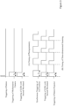
Fig. 3 is a timing diagram of a working handheld large-scale three-dimensional measurement scanner system according to one or more embodiments, wherein (A) is a photogrammetry timing and (B) is a 3D scanning timing. -
Fig. 4 is a schematic diagram of markers matching, wherein (A) is a marker set of the current frame in the device coordinate system and (B) is a marker library in the world coordinate system. - Embodiments of the present disclosure will be described below in reference to the drawings.
- Referring to
Figs. 1 to 4 , a handheld large-scale three-dimensional measurement scanner system having photogrammetric and three-dimensional scanning functions according to one or more embodiments of the present disclosure comprises two cameras at fixed positions, at least onepattern projector 104, a photogrammetric module, and a three-dimensional scanning module. At least one of the two cameras is amultipurpose camera 101 used for both photogrammetry and three-dimensional scanning. The two functional modules of the system can work independently or in association with each other. The photogrammetric module is configured to perform, by operating themultipurpose camera 101, global photogrammetry on a measured object and obtain three-dimensional coordinates of markers on a surface of the object. The three-dimensional scanning module is configured to perform, by operating the two cameras and the onepattern projector 104, three-dimensional scanning on the measured object by using the obtained markers as global positioning information of the measured object, and obtain three-dimensional contour data of the surface of the object. - In one or more embodiments, one of the two cameras is the
multipurpose camera 101 and the other is a single-purpose camera 102 used only for three-dimensional scanning. - In one or more embodiments, the photogrammetric module and the three-dimensional scanning module illuminate the markers disposed on or adhered to the surface of the object by providing, from supplemental light sources with two different wavebands, supplemental lighting on the surface of the measured object. The photogrammetric module provides supplemental lighting on the measured object from a supplemental light source with a first waveband, and the three-dimensional scanning module provides supplemental lighting on the measured object from a supplemental light source with a second waveband. The multipurpose camera uses a dual-waveband filter to filter out light outside the first waveband and the second waveband, and the single-purpose camera uses a single-waveband filter to filter out light outside the second waveband. The pattern projector projects a pattern on the surface of the measured object in the second waveband.
- In one or more embodiments, the first waveband is an infrared waveband, and the second waveband is a red waveband. The photogrammetric module adopts the infrared waveband. In other words, the first waveband of the supplemental light source that corresponds to the multipurpose camera and the first waveband of the dual-waveband filter used by the multipurpose camera are the infrared waveband. The three-dimensional scanning module adopts the red waveband. In other words, the second waveband of the supplemental light source that corresponds to the multipurpose camera and the second waveband of the dual-waveband filter used by the multipurpose camera are the red waveband, and the supplemental light source and the filter of the single-purpose camera use the red waveband. Alternatively, other wavebands may also be selected.
- In one or more embodiments, the multipurpose camera uses a relatively high default resolution when the photogrammetric module operates, and the multipurpose camera uses a relatively low resolution identical or similar to that used by the single-purpose camera when the three-dimensional scanning module operates.
- In one or more embodiments, the multipurpose camera adjusts its resolution by pixel merging or according to region of interest (ROI). Alternatively, other methods can also be used.
- A
frame member 103 that fixes the two cameras and the pattern projector is used to ensure that the relative position between the two cameras and the pattern projector is fixed. Thepattern projector 104 may be a single-line or multi-line line laser that operates with the second waveband. A multi-line laser can generate more contour strips in each frame, thereby improving the scanning efficiency. However, a specific verification mechanism is required for identifying (a method used by a handheld laser three-dimensional scanning system for verifying a plurality of laser lines is described in detail inChinese Patent Application No. 201610824489.3 light source 106 is a set of LEDs of which the center waveband is the second waveband, and the supplementallight source 105 is a set of LEDs of which the center waveband is the first waveband. When the photogrammetric module operates, only the LEDs with the first waveband on the multipurpose camera is activated to provide supplemental lighting on the scene. When the three-dimensional scanning module operates, the LEDs with the second waveband on the multipurpose camera and on the single-purpose camera simultaneously provide supplemental lighting on the measured object.Element 107 is a dual-waveband filter that passes the first waveband and the second waveband, andelement 108 is a single-waveband filter of which the center waveband is the second waveband. By cooperation of the supplemental lighting LEDs, the filters, and the pattern projector, the system can operate with the first waveband during global photogrammetry and with the second waveband during 3D scanning. - As shown in
Fig. 2 , the photogrammetric module of the system obtains the three-dimensional coordinates of the non-encoded markers on the surface of the measured object by the following steps: 1) placing encoded markers containing encoded information, non-encoded markers containing no encoded information, and a scale of a known length of which both ends are encoded markers, on the surface of the measured object; 2) operating the multipurpose camera to capture a set ofraw images 201 of the measured object from different positions and angles; 3) inputting theraw images 201 to a first two-dimensional (2D) image extractor to obtainimage 2D coordinates 211 of the encoded markers and the non-encoded markers in each image; 4) performing three-dimensional reconstruction of the encoded markers and the scale information by a first 3D reconstructor to obtain spatial three-dimensional coordinates of each encoded marker in a unified world coordinate system and anexterior orientation 213 of each image; and 5) using theimage 2D coordinates 212 of the non-encoded markers and theexterior orientation 213 of the image obtained by the first 2D image extractor to compute and obtain, by a second 3D reconstructor, three-dimensional coordinates 204 of the non-encoded markers in the world coordinate system. - As shown in
Fig. 2 , the three-dimensional scanning module obtains three-dimensional contour data of the surface of the measured object by the following steps: 1) inputting two-dimensional images 202, 203 simultaneously obtained by the two cameras to a second 2D image extractor to obtain image two-dimensional coordinates 221 of the non-encoded markers in each image and image two-dimensional coordinates of feature points projected by the pattern projector onto the surface of the measured object; 2) inputting the image two-dimensional coordinates 221 of the non-encoded markers in the two simultaneously obtained images and the known position relationship between the two cameras to a third 3D reconstructor to obtain three-dimensional coordinates 222 of the current non-encoded markers in the current device coordinate system; 3) inputting three-dimensional coordinates 222 of the current non-encoded markers in the device coordinate system obtained in a previous step to a marker matcher, wherein the marker matcher matches topological features of the inputted three-dimensional coordinates 222 of the markers in the device coordinate system with the non-encoded marker library 204 obtained by the photogrammetric module (alternatively, the three-dimensional scanning module may dynamically construct the maker library in real time during scanning by continuously identifying, splicing, and adding markers) to obtain three-dimensional coordinates of the current non-encoded markers in the world coordinate system and to further obtain an RT transformation matrix 223 under the transformation from the current device coordinate system to the world coordinate system; 4) inputting the image 2D coordinates 224 of the feature points projected by the pattern projector onto the surface of the measured object and obtained by the second 2D image extractor to a fourth 3D reconstructor to compute and obtain three-dimensional point cloud coordinate data 225 of the surface of the measured object in the device coordinate system; and 5) transforming, by a coordinate converter, a 3D point cloud 225 outputted in the previous step from the device coordinate system to the world coordinate system using the RT transformation matrix 223 obtained in step 3). - As shown in
Fig. 3 , in photogrammetry, a manual press on the button by a user triggers the multipurpose camera to capture a frame of image while simultaneously triggering the LEDs with the first waveband to provide flash supplemental lighting on the measured object, thereby completing one instance of photogrammetry. The work timing of 3D scanning is a cyclic process: at first, the system synchronously triggers the two cameras according to a set frequency while simultaneously triggering the LEDs with the second waveband to provide supplemental lighting on the non-encoded markers on the surface of the measured object and triggering the pattern projector to project a texture pattern on the surface of the measured object. - One way of implementing the first and second image extractors is by extracting a highlight connected region on the two-dimensional image, then identifying features such as the encoded markers, the non-encoded markers, and the contour lines projected by the pattern projector through an image matching algorithm, and then obtaining a coordinate set of the center coordinates of the markers and of the center line of the contour lines on the image. The relevant algorithms are mentioned in, for example,
Chinese Patent Application No. 201610824489.3 Chinese Patent No. ZL201410794661.6 - As shown in
Fig. 4 , one way of implementing the markers matching algorithm in the marker matcher is by counting associated parameters (one parameter in this embodiment, that is, the distance) of directed segments L1~Ln starting from each marker in the device coordinate system inputted by the third 3D reconstructor to adjacent markers within a particular distance into one data structure {D1, D2, ... , Dn}. Each element of the data structure is sorted and stored according to the value thereof. The data structure is compared with each subset of a set {{D11, D12, ... , D1n}, {D21, D22, ... , D2n}, ..., {Dm1, Dm2, ... , Dmn}} of all the sorted associated parameter sets sorted according to the value of the associated parameters of each marker of the marker set {W1, W2, ... , WM} in the world coordinate system obtained previously by photogrammetry (the comparison may be made in two coordinate systems because it is a scalar comparison) to find a marker k with the highest correlation as the matched marker. The method of evaluating the correlation may be simply looking for the smallest statistical value of associated parameter difference:

- Global photogrammetry is a fairly mature technology, which or an improvement of which is described in detail in, for example,
German Patent No. DE19925462 , Meβ- und Prüftystem sowie Meβ- und Prüfverfahren für einen dreidimensionalen Körper in Zusammenhang mit dessen Fertigung, orChinese Patent No. 200710195582.3 - While the invention has been described with respect to a limited number of embodiments, those skilled in the art, having benefit of this disclosure, will appreciate that other embodiments can be devised which do not depart from the scope as disclosed herein. Accordingly, the scope of the invention should be limited only by the attached claims.
Claims (3)
- A handheld large-scale three-dimensional measurement scanner system with photogrammetric and three-dimensional scanning functions, comprising:two cameras (101, 102) at fixed positions;at least one pattern projector (104);a photogrammetric module; anda three-dimensional scanning module,wherein one of the two cameras (101, 102) is a multipurpose camera (101) that performs photogrammetry and three-dimensional scanning and the other is a single-purpose camera (102) that performs three-dimensional scanning,wherein the photogrammetric module is configured to perform, by operating the multipurpose camera, global photogrammetry on a measured object and obtain three-dimensional coordinates of markers on a surface of the object, andwherein the three-dimensional scanning module is configured to perform, by operating the two cameras (101, 102) and the pattern projector (104), three-dimensional scanning on the measured object by using the obtained markers as global positioning information of the measured object, and obtain three-dimensional contour data of the surface of the object,wherein the photogrammetric module and the three-dimensional scanning module illuminate the markers disposed on or adhered to the surface of the object by providing, from supplemental light sources with two different wavebands, supplemental lighting on the surface of the measured object,wherein the photogrammetric module provides supplemental lighting on the measured object from a supplemental light source with a first waveband, and the three-dimensional scanning module provides supplemental lighting on the measured object from a supplemental light source with a second waveband,wherein the multipurpose camera (101) uses a dual-waveband filter to filter out light outside the first waveband and the second waveband, and the single-purpose camera (102) uses a single-waveband filter to filter out light outside the second waveband,wherein the pattern projector (104) projects a pattern on the surface of the measured object in the second waveband,wherein the multipurpose camera (101) uses a relatively high default resolution when the photogrammetric module operates, andwherein the multipurpose camera (101) uses a relatively low resolution identical or similar to that used by the single-purpose camera (102) when the three-dimensional scanning module operates.
- The handheld large-scale three-dimensional measurement scanner system with photogrammetric and three-dimensional scanning functions according to claim 1,
wherein the first waveband is an infrared waveband and the second waveband is a red waveband. - The handheld large-scale three-dimensional measurement scanner system with photogrammetric and three-dimensional scanning functions according to claim 1,
wherein the multipurpose camera (101) adjusts the resolution by pixel merging or according to region of interest (ROI).
Applications Claiming Priority (2)
| Application Number | Priority Date | Filing Date | Title |
|---|---|---|---|
| CN201710546383.6A CN107202554B (en) | 2017-07-06 | 2017-07-06 | It is provided simultaneously with photogrammetric and 3-D scanning function hand-held large scale three-dimensional measurement beam scanner system |
| PCT/CN2018/089863 WO2019007180A1 (en) | 2017-07-06 | 2018-06-05 | Handheld large-scale three-dimensional measurement scanner system simultaneously having photography measurement and three-dimensional scanning functions |
Publications (3)
| Publication Number | Publication Date |
|---|---|
| EP3650807A1 EP3650807A1 (en) | 2020-05-13 |
| EP3650807A4 EP3650807A4 (en) | 2021-04-28 |
| EP3650807B1 true EP3650807B1 (en) | 2023-02-22 |
Family
ID=59910800
Family Applications (1)
| Application Number | Title | Priority Date | Filing Date |
|---|---|---|---|
| EP18827623.2A Active EP3650807B1 (en) | 2017-07-06 | 2018-06-05 | Handheld large-scale three-dimensional measurement scanner system simultaneously having photography measurement and three-dimensional scanning functions |
Country Status (5)
| Country | Link |
|---|---|
| US (1) | US10914576B2 (en) |
| EP (1) | EP3650807B1 (en) |
| KR (1) | KR102209255B1 (en) |
| CN (1) | CN107202554B (en) |
| WO (1) | WO2019007180A1 (en) |
Families Citing this family (38)
| Publication number | Priority date | Publication date | Assignee | Title |
|---|---|---|---|---|
| CN107202554B (en) * | 2017-07-06 | 2018-07-06 | 杭州思看科技有限公司 | It is provided simultaneously with photogrammetric and 3-D scanning function hand-held large scale three-dimensional measurement beam scanner system |
| CN107976157A (en) * | 2017-12-26 | 2018-05-01 | 天远三维(天津)科技有限公司 | A kind of wireless hand-held three-dimensional scanning device in acquisition object surface three-dimensional morphology |
| JP6880512B2 (en) * | 2018-02-14 | 2021-06-02 | オムロン株式会社 | 3D measuring device, 3D measuring method and 3D measuring program |
| CN108827245A (en) * | 2018-05-17 | 2018-11-16 | 北京林业大学 | A kind of twin-lens portable forestry investigation apparatus |
| CN110608669A (en) * | 2018-06-15 | 2019-12-24 | 上海弼智仿生高科技有限公司 | Three-dimensional scanning method, device and system |
| CN108919597B (en) * | 2018-07-30 | 2024-02-13 | 深圳阜时科技有限公司 | An optical projection module |
| CN109963086B (en) * | 2018-07-30 | 2020-06-16 | 华为技术有限公司 | Time division multiplexing supplementary lighting imaging device and method |
| CN109584352B (en) * | 2018-08-21 | 2021-01-12 | 先临三维科技股份有限公司 | Three-dimensional scanning image acquisition and processing method and device and three-dimensional scanning equipment |
| CN109900221A (en) * | 2019-04-12 | 2019-06-18 | 杭州思看科技有限公司 | A kind of handheld three-dimensional scanning system |
| KR102217215B1 (en) * | 2019-08-12 | 2021-02-18 | 한다희 | Server and method for 3dimension model production using scale bar |
| CN110533009A (en) * | 2019-09-24 | 2019-12-03 | 广州魁科机电科技有限公司 | Large-scale workpiece 3-D scanning identification point intelligent identification Method and processing unit |
| CN111174728A (en) * | 2020-01-09 | 2020-05-19 | 武汉博雅弘拓科技有限公司 | RGB three-dimensional photographic scanner |
| CN111277811B (en) * | 2020-01-22 | 2021-11-09 | 上海爱德赞医疗科技有限公司 | Three-dimensional space camera and photographing method thereof |
| CN111524238B (en) * | 2020-04-23 | 2022-02-01 | 南京航空航天大学 | Three-dimensional point cloud deformation method based on coding point driving |
| EP3910287A1 (en) * | 2020-05-14 | 2021-11-17 | Fill Gesellschaft m.b.H. | Method and device for measuring a physical object |
| CN111811431A (en) * | 2020-06-12 | 2020-10-23 | 北京天远三维科技股份有限公司 | A three-dimensional scanner, three-dimensional scanning system and method |
| ES2890302B2 (en) * | 2020-07-02 | 2023-03-07 | Ideko S Coop | SYSTEM AND PROCESS FOR THE CONTROL OF THE UNCERTAINTY OF A PHOTOGRAMMETRIC MEASURER |
| CN111982061B (en) * | 2020-07-15 | 2022-08-23 | 杭州晨安科技股份有限公司 | Distance measurement method based on different focal lengths of binocular fixed-focus cameras |
| CN112002010B (en) * | 2020-08-12 | 2023-07-21 | 中国人民解放军总医院 | Damaged skin reconstruction method and reconstruction system based on line laser scanning |
| CN112268525B (en) * | 2020-10-23 | 2026-03-20 | 杭州先临天远三维检测技术有限公司 | 3D scanning methods and 3D scanning equipment |
| US12483625B2 (en) * | 2020-12-23 | 2025-11-25 | Faro Technologies, Inc. | Handheld scanner that transfers data and power over ethernet |
| US12487073B2 (en) * | 2020-12-23 | 2025-12-02 | Faro Technologies, Inc. | Speckle reduction methods in line scanners |
| US20220316869A1 (en) * | 2020-12-23 | 2022-10-06 | Faro Technologies, Inc. | Line scanner having integrated processing capability |
| US11908162B2 (en) * | 2020-12-23 | 2024-02-20 | Faro Technologies, Inc. | Line scanner having target-tracking and geometry-tracking modes |
| CN113063370B (en) * | 2021-03-10 | 2023-01-31 | 思看科技(杭州)股份有限公司 | Calibration method, system, electronic device and storage medium of multiband scanner |
| CN113225447B (en) * | 2021-04-14 | 2024-03-26 | 思看科技(杭州)股份有限公司 | Three-dimensional scanning system, data processing method, data processing device and computer equipment |
| KR102489494B1 (en) | 2021-04-26 | 2023-01-18 | 정내권 | A platform and calculation method that calculates the contribution due to carbon emission generation using a blockchain and calculates the payment, contribution, investment, and profit situation for the contribution |
| CN113310427B (en) * | 2021-05-18 | 2023-03-07 | 思看科技(杭州)股份有限公司 | Three-dimensional scanning system and three-dimensional scanning method |
| CN115580766A (en) * | 2021-06-21 | 2023-01-06 | 中兴通讯股份有限公司 | Camera device, method, electronic device and storage medium |
| CN114111624B (en) * | 2021-10-28 | 2024-06-21 | 武汉中观自动化科技有限公司 | Handheld three-dimensional scanning method, equipment and medium with mark point projection device |
| CN116266379A (en) * | 2021-12-17 | 2023-06-20 | 先临三维科技股份有限公司 | Three-dimensional scanning processing method, device and three-dimensional scanning equipment |
| WO2023198283A1 (en) * | 2022-04-13 | 2023-10-19 | Carl Zeiss GOM Metrology GmbH | Method and device for a photogrammetric measurement |
| CN115435754B (en) * | 2022-08-03 | 2023-10-13 | 思看科技(杭州)股份有限公司 | Photogrammetry method, device, three-dimensional scanning method and three-dimensional scanning system |
| CN115371549A (en) * | 2022-08-10 | 2022-11-22 | 武汉中观自动化科技有限公司 | Three-dimensional laser scanning method and system |
| CN115325959B (en) * | 2022-10-13 | 2023-03-07 | 思看科技(杭州)股份有限公司 | Three-dimensional scanning system and method |
| CN115727759A (en) * | 2022-11-18 | 2023-03-03 | 中国科学院长春光学精密机械与物理研究所 | A three-dimensional scanner with handheld automatic double-scanning function and scanning method |
| CN117372511B (en) * | 2023-12-05 | 2024-02-23 | 尚特杰电力科技有限公司 | Photovoltaic string positioning method, device and system and electronic equipment |
| EP4722643A1 (en) | 2024-10-04 | 2026-04-08 | D2 Technology Maquinas E Equipamentos Industrais Lda | Stone slab scanner for generating a 3d surface map of a stone slab surface and operation method thereof |
Family Cites Families (55)
| Publication number | Priority date | Publication date | Assignee | Title |
|---|---|---|---|---|
| US4702605A (en) * | 1986-02-03 | 1987-10-27 | Robotic Vision Systems, Inc. | Rocker arm sensor |
| US4957369A (en) * | 1989-01-23 | 1990-09-18 | California Institute Of Technology | Apparatus for measuring three-dimensional surface geometries |
| JP3414624B2 (en) * | 1997-09-16 | 2003-06-09 | 松下電器産業株式会社 | Real-time range finder |
| DE19925462C1 (en) | 1999-06-02 | 2001-02-15 | Daimler Chrysler Ag | Method and system for measuring and testing a 3D body during its manufacture has a measuring system with an optical 3D sensor, a data processor and a testing system storing 3D theoretical data records of a 3D body's surface. |
| WO2002010720A2 (en) * | 2000-07-31 | 2002-02-07 | Geodetic Services, Inc. | Photogrammetric image correlation and measurement system and method |
| KR100502560B1 (en) * | 2002-07-25 | 2005-07-20 | 주식회사 솔루션닉스 | Apparatus and Method for Registering Multiple Three Dimensional Scan Data by using Optical Marker |
| JP2004110804A (en) * | 2002-08-28 | 2004-04-08 | Fuji Xerox Co Ltd | Three-dimensional image photographing equipment and method |
| JP2004239886A (en) * | 2002-12-11 | 2004-08-26 | Fuji Xerox Co Ltd | Three-dimensional image imaging apparatus and method |
| JP2005215917A (en) * | 2004-01-29 | 2005-08-11 | Hitachi Plant Eng & Constr Co Ltd | Construction drawing creation support method and replacement model creation method |
| US20120182403A1 (en) * | 2004-09-30 | 2012-07-19 | Eric Belk Lange | Stereoscopic imaging |
| CA2600926C (en) * | 2005-03-11 | 2009-06-09 | Creaform Inc. | Auto-referenced system and apparatus for three-dimensional scanning |
| US8082120B2 (en) * | 2005-03-11 | 2011-12-20 | Creaform Inc. | Hand-held self-referenced apparatus for three-dimensional scanning |
| CN100343625C (en) * | 2005-12-05 | 2007-10-17 | 天津大学 | Measuring splice method and device of large three-dimensional body shape based on splicing target |
| US9170097B2 (en) * | 2008-04-01 | 2015-10-27 | Perceptron, Inc. | Hybrid system |
| JP5322206B2 (en) * | 2008-05-07 | 2013-10-23 | 国立大学法人 香川大学 | Three-dimensional shape measuring method and apparatus |
| WO2010015086A1 (en) * | 2008-08-06 | 2010-02-11 | Creaform Inc. | System for adaptive three-dimensional scanning of surface characteristics |
| US8582824B2 (en) * | 2009-06-25 | 2013-11-12 | Twin Coast Metrology | Cell feature extraction and labeling thereof |
| CN102062588B (en) * | 2009-11-11 | 2012-07-04 | 中国科学院沈阳自动化研究所 | Computer binocular vision denture scanning device and three-dimensional reconstruction method thereof |
| CN101706262B (en) * | 2009-11-19 | 2011-05-25 | 天津大学 | Interference-free precision measurement method for super-large spatially complex surfaces |
| CA2686904C (en) * | 2009-12-02 | 2012-04-24 | Creaform Inc. | Hand-held self-referenced apparatus for three-dimensional scanning |
| CN101853528B (en) * | 2010-05-10 | 2011-12-07 | 沈阳雅克科技有限公司 | Hand-held three-dimensional surface information extraction method and extractor thereof |
| US9014848B2 (en) * | 2010-05-20 | 2015-04-21 | Irobot Corporation | Mobile robot system |
| EP2400261A1 (en) * | 2010-06-21 | 2011-12-28 | Leica Geosystems AG | Optical measurement method and system for determining 3D coordination in a measuring object surface |
| DE102011011360A1 (en) * | 2011-02-16 | 2012-08-16 | Steinbichler Optotechnik Gmbh | Apparatus and method for determining the 3-D coordinates of an object and for calibrating an industrial robot |
| US9686532B2 (en) * | 2011-04-15 | 2017-06-20 | Faro Technologies, Inc. | System and method of acquiring three-dimensional coordinates using multiple coordinate measurement devices |
| US9482529B2 (en) * | 2011-04-15 | 2016-11-01 | Faro Technologies, Inc. | Three-dimensional coordinate scanner and method of operation |
| EP2527784A1 (en) * | 2011-05-19 | 2012-11-28 | Hexagon Technology Center GmbH | Optical measurement method and system for determining 3D coordinates of a measured object surface |
| WO2013096704A1 (en) * | 2011-12-20 | 2013-06-27 | Sadar 3D, Inc. | Systems, apparatus, and methods for acquisition and use of image data |
| US9200899B2 (en) * | 2012-03-22 | 2015-12-01 | Virtek Vision International, Inc. | Laser projection system and method |
| DE202012104890U1 (en) * | 2012-12-14 | 2013-03-05 | Faro Technologies, Inc. | Device for optically scanning and measuring an environment |
| DE102012112322B4 (en) * | 2012-12-14 | 2015-11-05 | Faro Technologies, Inc. | Method for optically scanning and measuring an environment |
| DE102012112321B4 (en) * | 2012-12-14 | 2015-03-05 | Faro Technologies, Inc. | Device for optically scanning and measuring an environment |
| US9041914B2 (en) * | 2013-03-15 | 2015-05-26 | Faro Technologies, Inc. | Three-dimensional coordinate scanner and method of operation |
| US20150070468A1 (en) * | 2013-09-10 | 2015-03-12 | Faro Technologies, Inc. | Use of a three-dimensional imager's point cloud data to set the scale for photogrammetry |
| US10089415B2 (en) * | 2013-12-19 | 2018-10-02 | Faro Technologies, Inc. | Three-dimensional coordinate scanner and method of operation |
| DE102013114707A1 (en) * | 2013-12-20 | 2015-06-25 | EXTEND3D GmbH | Method for carrying out and controlling a processing step on a workpiece |
| EP3149428A1 (en) * | 2014-05-29 | 2017-04-05 | Northwestern University | Motion contrast depth scanning |
| CN104165600B (en) * | 2014-07-03 | 2016-10-05 | 杭州鼎热科技有限公司 | A kind of wireless handheld 3D laser scanning system |
| JP2017528714A (en) * | 2014-09-10 | 2017-09-28 | ファロ テクノロジーズ インコーポレーテッド | Method for optical measurement of three-dimensional coordinates and control of a three-dimensional measuring device |
| US9602811B2 (en) * | 2014-09-10 | 2017-03-21 | Faro Technologies, Inc. | Method for optically measuring three-dimensional coordinates and controlling a three-dimensional measuring device |
| DE102014013678B3 (en) * | 2014-09-10 | 2015-12-03 | Faro Technologies, Inc. | Method for optically sensing and measuring an environment with a handheld scanner and gesture control |
| US9671221B2 (en) * | 2014-09-10 | 2017-06-06 | Faro Technologies, Inc. | Portable device for optically measuring three-dimensional coordinates |
| DE102014013677B4 (en) * | 2014-09-10 | 2017-06-22 | Faro Technologies, Inc. | Method for optically scanning and measuring an environment with a handheld scanner and subdivided display |
| US9693040B2 (en) * | 2014-09-10 | 2017-06-27 | Faro Technologies, Inc. | Method for optically measuring three-dimensional coordinates and calibration of a three-dimensional measuring device |
| CN104501740B (en) * | 2014-12-18 | 2017-05-10 | 杭州鼎热科技有限公司 | Handheld laser three-dimension scanning method and handheld laser three-dimension scanning equipment based on mark point trajectory tracking |
| CN107076549B (en) * | 2015-05-29 | 2019-05-10 | 新日铁住金株式会社 | Shape inspection device of metal body and shape inspection method of metal body |
| CN104964656A (en) * | 2015-06-26 | 2015-10-07 | 天津大学 | Self-positioning flowing-type rapid scanning measuring device and method based on inertial navigation |
| US10455216B2 (en) * | 2015-08-19 | 2019-10-22 | Faro Technologies, Inc. | Three-dimensional imager |
| US20170094251A1 (en) * | 2015-09-30 | 2017-03-30 | Faro Technologies, Inc. | Three-dimensional imager that includes a dichroic camera |
| FR3044429B1 (en) * | 2015-11-26 | 2018-01-05 | Ak Optique | METHOD FOR MANUFACTURING A CUSTOM GOGGLE FRAME |
| CN105547189B (en) * | 2015-12-14 | 2018-01-23 | 南京航空航天大学 | High-precision optical method for three-dimensional measurement based on mutative scale |
| US10834377B2 (en) * | 2016-08-29 | 2020-11-10 | Faro Technologies, Inc. | Forensic three-dimensional measurement device |
| CN107202554B (en) * | 2017-07-06 | 2018-07-06 | 杭州思看科技有限公司 | It is provided simultaneously with photogrammetric and 3-D scanning function hand-held large scale three-dimensional measurement beam scanner system |
| US10458783B2 (en) * | 2017-10-13 | 2019-10-29 | Faro Technologies, Inc. | Three-dimensional scanner having pixel memory |
| USD875573S1 (en) * | 2018-09-26 | 2020-02-18 | Hexagon Metrology, Inc. | Scanning device |
-
2017
- 2017-07-06 CN CN201710546383.6A patent/CN107202554B/en active Active
-
2018
- 2018-06-05 EP EP18827623.2A patent/EP3650807B1/en active Active
- 2018-06-05 WO PCT/CN2018/089863 patent/WO2019007180A1/en not_active Ceased
- 2018-06-05 KR KR1020207003444A patent/KR102209255B1/en active Active
- 2018-06-05 US US16/628,967 patent/US10914576B2/en active Active
Also Published As
| Publication number | Publication date |
|---|---|
| US20200225030A1 (en) | 2020-07-16 |
| KR20200016994A (en) | 2020-02-17 |
| CN107202554B (en) | 2018-07-06 |
| WO2019007180A1 (en) | 2019-01-10 |
| US10914576B2 (en) | 2021-02-09 |
| CN107202554A (en) | 2017-09-26 |
| EP3650807A4 (en) | 2021-04-28 |
| KR102209255B1 (en) | 2021-01-29 |
| EP3650807A1 (en) | 2020-05-13 |
Similar Documents
| Publication | Publication Date | Title |
|---|---|---|
| EP3650807B1 (en) | Handheld large-scale three-dimensional measurement scanner system simultaneously having photography measurement and three-dimensional scanning functions | |
| US9392262B2 (en) | System and method for 3D reconstruction using multiple multi-channel cameras | |
| EP3392831B1 (en) | Three-dimensional sensor system and three-dimensional data acquisition method | |
| CN107635129B (en) | Three-dimensional trinocular camera device and depth fusion method | |
| CA3040002C (en) | A device and method for obtaining distance information from views | |
| EP2870428B1 (en) | System and method for 3d measurement of the surface geometry of an object | |
| CN110462686B (en) | Apparatus and method for obtaining depth information from a scene | |
| TWI555379B (en) | Panoramic fisheye camera image correction, synthesis and depth of field reconstruction method and system thereof | |
| CN206905709U (en) | Hand-held large scale three-dimensional measurement scanner | |
| CN110657785A (en) | Efficient scene depth information acquisition method and system | |
| US11803982B2 (en) | Image processing device and three-dimensional measuring system | |
| US11348271B2 (en) | Image processing device and three-dimensional measuring system | |
| US12125226B2 (en) | Image processing device, three-dimensional measurement system, and image processing method | |
| US9245375B2 (en) | Active lighting for stereo reconstruction of edges | |
| CN110705487B (en) | Palm print acquisition equipment and method and image acquisition device thereof | |
| CN112750157B (en) | Depth image generation method and device | |
| JP2011095131A (en) | Image processing method | |
| KR20120056668A (en) | Apparatus and method for recovering 3 dimensional information | |
| JP7561911B2 (en) | Imaging device, imaging method, and imaging program | |
| CN114341940B (en) | Image processing device, three-dimensional measurement system, image processing method | |
| JP2002013918A (en) | Three-dimensional image forming device and three- dimensional image forming method | |
| CN117808858A (en) | Pipeline data acquisition system, method, device, equipment and storage medium | |
| CN120852273A (en) | Pavement crack recognition method based on binocular bird's-eye view image and improved YOLOv8 | |
| CN115797995A (en) | Face living body detection method, electronic equipment and storage medium |
Legal Events
| Date | Code | Title | Description |
|---|---|---|---|
| STAA | Information on the status of an ep patent application or granted ep patent |
Free format text: STATUS: THE INTERNATIONAL PUBLICATION HAS BEEN MADE |
|
| PUAI | Public reference made under article 153(3) epc to a published international application that has entered the european phase |
Free format text: ORIGINAL CODE: 0009012 |
|
| STAA | Information on the status of an ep patent application or granted ep patent |
Free format text: STATUS: REQUEST FOR EXAMINATION WAS MADE |
|
| 17P | Request for examination filed |
Effective date: 20200206 |
|
| AK | Designated contracting states |
Kind code of ref document: A1 Designated state(s): AL AT BE BG CH CY CZ DE DK EE ES FI FR GB GR HR HU IE IS IT LI LT LU LV MC MK MT NL NO PL PT RO RS SE SI SK SM TR |
|
| AX | Request for extension of the european patent |
Extension state: BA ME |
|
| DAV | Request for validation of the european patent (deleted) | ||
| DAX | Request for extension of the european patent (deleted) | ||
| RIN1 | Information on inventor provided before grant (corrected) |
Inventor name: CHEN, SHANGJIAN Inventor name: ZHENG, JUN |
|
| A4 | Supplementary search report drawn up and despatched |
Effective date: 20210326 |
|
| RIC1 | Information provided on ipc code assigned before grant |
Ipc: G01B 11/25 20060101AFI20210322BHEP Ipc: G01B 11/245 20060101ALI20210322BHEP |
|
| STAA | Information on the status of an ep patent application or granted ep patent |
Free format text: STATUS: EXAMINATION IS IN PROGRESS |
|
| 17Q | First examination report despatched |
Effective date: 20211203 |
|
| GRAP | Despatch of communication of intention to grant a patent |
Free format text: ORIGINAL CODE: EPIDOSNIGR1 |
|
| STAA | Information on the status of an ep patent application or granted ep patent |
Free format text: STATUS: GRANT OF PATENT IS INTENDED |
|
| INTG | Intention to grant announced |
Effective date: 20220817 |
|
| GRAS | Grant fee paid |
Free format text: ORIGINAL CODE: EPIDOSNIGR3 |
|
| GRAA | (expected) grant |
Free format text: ORIGINAL CODE: 0009210 |
|
| STAA | Information on the status of an ep patent application or granted ep patent |
Free format text: STATUS: THE PATENT HAS BEEN GRANTED |
|
| AK | Designated contracting states |
Kind code of ref document: B1 Designated state(s): AL AT BE BG CH CY CZ DE DK EE ES FI FR GB GR HR HU IE IS IT LI LT LU LV MC MK MT NL NO PL PT RO RS SE SI SK SM TR |
|
| RAP3 | Party data changed (applicant data changed or rights of an application transferred) |
Owner name: SCANTECH (HANGZHOU) CO., LTD. |
|
| REG | Reference to a national code |
Ref country code: GB Ref legal event code: FG4D |
|
| REG | Reference to a national code |
Ref country code: CH Ref legal event code: EP |
|
| REG | Reference to a national code |
Ref country code: DE Ref legal event code: R096 Ref document number: 602018046489 Country of ref document: DE |
|
| REG | Reference to a national code |
Ref country code: AT Ref legal event code: REF Ref document number: 1549763 Country of ref document: AT Kind code of ref document: T Effective date: 20230315 Ref country code: IE Ref legal event code: FG4D |
|
| REG | Reference to a national code |
Ref country code: LT Ref legal event code: MG9D |
|
| REG | Reference to a national code |
Ref country code: NL Ref legal event code: MP Effective date: 20230222 |
|
| REG | Reference to a national code |
Ref country code: AT Ref legal event code: MK05 Ref document number: 1549763 Country of ref document: AT Kind code of ref document: T Effective date: 20230222 |
|
| PG25 | Lapsed in a contracting state [announced via postgrant information from national office to epo] |
Ref country code: RS Free format text: LAPSE BECAUSE OF FAILURE TO SUBMIT A TRANSLATION OF THE DESCRIPTION OR TO PAY THE FEE WITHIN THE PRESCRIBED TIME-LIMIT Effective date: 20230222 Ref country code: PT Free format text: LAPSE BECAUSE OF FAILURE TO SUBMIT A TRANSLATION OF THE DESCRIPTION OR TO PAY THE FEE WITHIN THE PRESCRIBED TIME-LIMIT Effective date: 20230622 Ref country code: NO Free format text: LAPSE BECAUSE OF FAILURE TO SUBMIT A TRANSLATION OF THE DESCRIPTION OR TO PAY THE FEE WITHIN THE PRESCRIBED TIME-LIMIT Effective date: 20230522 Ref country code: NL Free format text: LAPSE BECAUSE OF FAILURE TO SUBMIT A TRANSLATION OF THE DESCRIPTION OR TO PAY THE FEE WITHIN THE PRESCRIBED TIME-LIMIT Effective date: 20230222 Ref country code: LV Free format text: LAPSE BECAUSE OF FAILURE TO SUBMIT A TRANSLATION OF THE DESCRIPTION OR TO PAY THE FEE WITHIN THE PRESCRIBED TIME-LIMIT Effective date: 20230222 Ref country code: LT Free format text: LAPSE BECAUSE OF FAILURE TO SUBMIT A TRANSLATION OF THE DESCRIPTION OR TO PAY THE FEE WITHIN THE PRESCRIBED TIME-LIMIT Effective date: 20230222 Ref country code: HR Free format text: LAPSE BECAUSE OF FAILURE TO SUBMIT A TRANSLATION OF THE DESCRIPTION OR TO PAY THE FEE WITHIN THE PRESCRIBED TIME-LIMIT Effective date: 20230222 Ref country code: ES Free format text: LAPSE BECAUSE OF FAILURE TO SUBMIT A TRANSLATION OF THE DESCRIPTION OR TO PAY THE FEE WITHIN THE PRESCRIBED TIME-LIMIT Effective date: 20230222 Ref country code: AT Free format text: LAPSE BECAUSE OF FAILURE TO SUBMIT A TRANSLATION OF THE DESCRIPTION OR TO PAY THE FEE WITHIN THE PRESCRIBED TIME-LIMIT Effective date: 20230222 |
|
| PG25 | Lapsed in a contracting state [announced via postgrant information from national office to epo] |
Ref country code: SE Free format text: LAPSE BECAUSE OF FAILURE TO SUBMIT A TRANSLATION OF THE DESCRIPTION OR TO PAY THE FEE WITHIN THE PRESCRIBED TIME-LIMIT Effective date: 20230222 Ref country code: PL Free format text: LAPSE BECAUSE OF FAILURE TO SUBMIT A TRANSLATION OF THE DESCRIPTION OR TO PAY THE FEE WITHIN THE PRESCRIBED TIME-LIMIT Effective date: 20230222 Ref country code: IS Free format text: LAPSE BECAUSE OF FAILURE TO SUBMIT A TRANSLATION OF THE DESCRIPTION OR TO PAY THE FEE WITHIN THE PRESCRIBED TIME-LIMIT Effective date: 20230622 Ref country code: GR Free format text: LAPSE BECAUSE OF FAILURE TO SUBMIT A TRANSLATION OF THE DESCRIPTION OR TO PAY THE FEE WITHIN THE PRESCRIBED TIME-LIMIT Effective date: 20230523 Ref country code: FI Free format text: LAPSE BECAUSE OF FAILURE TO SUBMIT A TRANSLATION OF THE DESCRIPTION OR TO PAY THE FEE WITHIN THE PRESCRIBED TIME-LIMIT Effective date: 20230222 |
|
| PG25 | Lapsed in a contracting state [announced via postgrant information from national office to epo] |
Ref country code: SM Free format text: LAPSE BECAUSE OF FAILURE TO SUBMIT A TRANSLATION OF THE DESCRIPTION OR TO PAY THE FEE WITHIN THE PRESCRIBED TIME-LIMIT Effective date: 20230222 Ref country code: RO Free format text: LAPSE BECAUSE OF FAILURE TO SUBMIT A TRANSLATION OF THE DESCRIPTION OR TO PAY THE FEE WITHIN THE PRESCRIBED TIME-LIMIT Effective date: 20230222 Ref country code: EE Free format text: LAPSE BECAUSE OF FAILURE TO SUBMIT A TRANSLATION OF THE DESCRIPTION OR TO PAY THE FEE WITHIN THE PRESCRIBED TIME-LIMIT Effective date: 20230222 Ref country code: DK Free format text: LAPSE BECAUSE OF FAILURE TO SUBMIT A TRANSLATION OF THE DESCRIPTION OR TO PAY THE FEE WITHIN THE PRESCRIBED TIME-LIMIT Effective date: 20230222 Ref country code: CZ Free format text: LAPSE BECAUSE OF FAILURE TO SUBMIT A TRANSLATION OF THE DESCRIPTION OR TO PAY THE FEE WITHIN THE PRESCRIBED TIME-LIMIT Effective date: 20230222 |
|
| REG | Reference to a national code |
Ref country code: DE Ref legal event code: R097 Ref document number: 602018046489 Country of ref document: DE |
|
| PG25 | Lapsed in a contracting state [announced via postgrant information from national office to epo] |
Ref country code: SK Free format text: LAPSE BECAUSE OF FAILURE TO SUBMIT A TRANSLATION OF THE DESCRIPTION OR TO PAY THE FEE WITHIN THE PRESCRIBED TIME-LIMIT Effective date: 20230222 |
|
| PLBE | No opposition filed within time limit |
Free format text: ORIGINAL CODE: 0009261 |
|
| STAA | Information on the status of an ep patent application or granted ep patent |
Free format text: STATUS: NO OPPOSITION FILED WITHIN TIME LIMIT |
|
| PG25 | Lapsed in a contracting state [announced via postgrant information from national office to epo] |
Ref country code: MC Free format text: LAPSE BECAUSE OF FAILURE TO SUBMIT A TRANSLATION OF THE DESCRIPTION OR TO PAY THE FEE WITHIN THE PRESCRIBED TIME-LIMIT Effective date: 20230222 |
|
| 26N | No opposition filed |
Effective date: 20231123 |
|
| PG25 | Lapsed in a contracting state [announced via postgrant information from national office to epo] |
Ref country code: SI Free format text: LAPSE BECAUSE OF FAILURE TO SUBMIT A TRANSLATION OF THE DESCRIPTION OR TO PAY THE FEE WITHIN THE PRESCRIBED TIME-LIMIT Effective date: 20230222 Ref country code: MC Free format text: LAPSE BECAUSE OF FAILURE TO SUBMIT A TRANSLATION OF THE DESCRIPTION OR TO PAY THE FEE WITHIN THE PRESCRIBED TIME-LIMIT Effective date: 20230222 |
|
| REG | Reference to a national code |
Ref country code: CH Ref legal event code: PL |
|
| REG | Reference to a national code |
Ref country code: BE Ref legal event code: MM Effective date: 20230630 |
|
| PG25 | Lapsed in a contracting state [announced via postgrant information from national office to epo] |
Ref country code: LU Free format text: LAPSE BECAUSE OF NON-PAYMENT OF DUE FEES Effective date: 20230605 |
|
| REG | Reference to a national code |
Ref country code: IE Ref legal event code: MM4A |
|
| PG25 | Lapsed in a contracting state [announced via postgrant information from national office to epo] |
Ref country code: LU Free format text: LAPSE BECAUSE OF NON-PAYMENT OF DUE FEES Effective date: 20230605 |
|
| PG25 | Lapsed in a contracting state [announced via postgrant information from national office to epo] |
Ref country code: IE Free format text: LAPSE BECAUSE OF NON-PAYMENT OF DUE FEES Effective date: 20230605 |
|
| PG25 | Lapsed in a contracting state [announced via postgrant information from national office to epo] |
Ref country code: IE Free format text: LAPSE BECAUSE OF NON-PAYMENT OF DUE FEES Effective date: 20230605 Ref country code: CH Free format text: LAPSE BECAUSE OF NON-PAYMENT OF DUE FEES Effective date: 20230630 |
|
| PG25 | Lapsed in a contracting state [announced via postgrant information from national office to epo] |
Ref country code: IT Free format text: LAPSE BECAUSE OF FAILURE TO SUBMIT A TRANSLATION OF THE DESCRIPTION OR TO PAY THE FEE WITHIN THE PRESCRIBED TIME-LIMIT Effective date: 20230222 Ref country code: BE Free format text: LAPSE BECAUSE OF NON-PAYMENT OF DUE FEES Effective date: 20230630 |
|
| PG25 | Lapsed in a contracting state [announced via postgrant information from national office to epo] |
Ref country code: BG Free format text: LAPSE BECAUSE OF FAILURE TO SUBMIT A TRANSLATION OF THE DESCRIPTION OR TO PAY THE FEE WITHIN THE PRESCRIBED TIME-LIMIT Effective date: 20230222 |
|
| PG25 | Lapsed in a contracting state [announced via postgrant information from national office to epo] |
Ref country code: BG Free format text: LAPSE BECAUSE OF FAILURE TO SUBMIT A TRANSLATION OF THE DESCRIPTION OR TO PAY THE FEE WITHIN THE PRESCRIBED TIME-LIMIT Effective date: 20230222 |
|
| PGFP | Annual fee paid to national office [announced via postgrant information from national office to epo] |
Ref country code: DE Payment date: 20250611 Year of fee payment: 8 |
|
| PGFP | Annual fee paid to national office [announced via postgrant information from national office to epo] |
Ref country code: GB Payment date: 20250605 Year of fee payment: 8 |
|
| PGFP | Annual fee paid to national office [announced via postgrant information from national office to epo] |
Ref country code: FR Payment date: 20250610 Year of fee payment: 8 |
|
| PG25 | Lapsed in a contracting state [announced via postgrant information from national office to epo] |
Ref country code: CY Free format text: LAPSE BECAUSE OF FAILURE TO SUBMIT A TRANSLATION OF THE DESCRIPTION OR TO PAY THE FEE WITHIN THE PRESCRIBED TIME-LIMIT; INVALID AB INITIO Effective date: 20180605 |
|
| PG25 | Lapsed in a contracting state [announced via postgrant information from national office to epo] |
Ref country code: HU Free format text: LAPSE BECAUSE OF FAILURE TO SUBMIT A TRANSLATION OF THE DESCRIPTION OR TO PAY THE FEE WITHIN THE PRESCRIBED TIME-LIMIT; INVALID AB INITIO Effective date: 20180605 |
|
| PG25 | Lapsed in a contracting state [announced via postgrant information from national office to epo] |
Ref country code: TR Free format text: LAPSE BECAUSE OF FAILURE TO SUBMIT A TRANSLATION OF THE DESCRIPTION OR TO PAY THE FEE WITHIN THE PRESCRIBED TIME-LIMIT Effective date: 20230222 |