EP3650765A1 - Air conditioning outdoor unit and air conditioner having same - Google Patents
Air conditioning outdoor unit and air conditioner having same Download PDFInfo
- Publication number
- EP3650765A1 EP3650765A1 EP19812898.5A EP19812898A EP3650765A1 EP 3650765 A1 EP3650765 A1 EP 3650765A1 EP 19812898 A EP19812898 A EP 19812898A EP 3650765 A1 EP3650765 A1 EP 3650765A1
- Authority
- EP
- European Patent Office
- Prior art keywords
- electronic control
- baffle
- sub
- outdoor unit
- waterproof member
- Prior art date
- Legal status (The legal status is an assumption and is not a legal conclusion. Google has not performed a legal analysis and makes no representation as to the accuracy of the status listed.)
- Granted
Links
Images


Classifications
-
- F—MECHANICAL ENGINEERING; LIGHTING; HEATING; WEAPONS; BLASTING
- F24—HEATING; RANGES; VENTILATING
- F24F—AIR-CONDITIONING; AIR-HUMIDIFICATION; VENTILATION; USE OF AIR CURRENTS FOR SCREENING
- F24F1/00—Room units for air-conditioning, e.g. separate or self-contained units or units receiving primary air from a central station
- F24F1/06—Separate outdoor units, e.g. outdoor unit to be linked to a separate room comprising a compressor and a heat exchanger
- F24F1/20—Electric components for separate outdoor units
- F24F1/24—Cooling of electric components
-
- F—MECHANICAL ENGINEERING; LIGHTING; HEATING; WEAPONS; BLASTING
- F24—HEATING; RANGES; VENTILATING
- F24F—AIR-CONDITIONING; AIR-HUMIDIFICATION; VENTILATION; USE OF AIR CURRENTS FOR SCREENING
- F24F1/00—Room units for air-conditioning, e.g. separate or self-contained units or units receiving primary air from a central station
- F24F1/06—Separate outdoor units, e.g. outdoor unit to be linked to a separate room comprising a compressor and a heat exchanger
- F24F1/20—Electric components for separate outdoor units
- F24F1/22—Arrangement or mounting thereof
-
- F—MECHANICAL ENGINEERING; LIGHTING; HEATING; WEAPONS; BLASTING
- F24—HEATING; RANGES; VENTILATING
- F24F—AIR-CONDITIONING; AIR-HUMIDIFICATION; VENTILATION; USE OF AIR CURRENTS FOR SCREENING
- F24F1/00—Room units for air-conditioning, e.g. separate or self-contained units or units receiving primary air from a central station
- F24F1/06—Separate outdoor units, e.g. outdoor unit to be linked to a separate room comprising a compressor and a heat exchanger
- F24F1/46—Component arrangements in separate outdoor units
- F24F1/48—Component arrangements in separate outdoor units characterised by air airflow, e.g. inlet or outlet airflow
Definitions
- the present disclosure relates to a field of manufacturing technologies for air conditioners, and more particularly, to an outdoor unit for an air conditioner and an air conditioner having the same.
- an electronic control element on an electronic component of an outdoor unit for an air conditioner such as a small multi-coupled-side-air-output outdoor unit, generates heat during operation.
- the normal operation and service life of the electronic control element will be affected, if the heat cannot be discharged.
- failures of the electronic control element may be caused, and moreover the outdoor unit for an air conditioner cannot operate normally.
- an objective of the present disclosure provides an outdoor unit for an air conditioner. Quick heat dispassion can be provided to the electronic control component of the outdoor unit for an air conditioner, and water and the like hardly fall on the electronic control component.
- Another objective of the present disclosure provides an air conditioner with the outdoor unit.
- the outdoor unit for an air conditioner includes: a body; a rotor arranged in the body; a welded member for electronic control arranged in a top portion within the body, defining at least one opening in a bottom portion of the welded member for electronic control, and provided with an electronic control component in the welded member for electronic control; a waterproof member connected to the bottom portion of the welded member for electronic control, and being opposite to the opening, defining an airflow passage in communication with the opening cooperatively with the welded member for electronic control, having two ends separately spaced apart from the welded member for electronic control to define two airflow outlets in communication with the airflow passage; and at least one baffle arranged in the airflow passage to prevent liquid from entering the welded member for electronic control through the airflow passage.
- the waterproof member is arranged at the bottom portion of the welded member for electronic control and opposite the opening, the waterproof member and the welded member for electronic control cooperatively define the airflow passage in communication with the opening and the two airflow outlets in communication with the airflow passage, and the baffle is arranged in the airflow passage, quick heat dissipation for the electronic control component can be realized, and water and the like hardly enter the welded member for electronic control through the opening, such that the electronic control component in the welded member for electronic control can normally operate.
- the waterproof member is open at a top portion, two sides of the waterproof member in a width direction are provided with connecting parts extending outwards respectively, the waterproof member is connected to the bottom portion of the welded member for electronic control by means of the connecting parts, and two ends of the waterproof member in the length direction are spaced apart from the welded member for electronic control to define the two airflow outlets respectively.
- At least one end of the two ends of the waterproof member in the length direction is provided with an incline part, the incline part obliquely extends upwards in a direction away from a center of the waterproof member and has a free end, the free end of the incline part is provided with a flange horizontally extending outwards, an upper surface of the flange is spaced apart from the bottom portion of the welded member for electronic control to define the airflow outlet.
- At least one end of the two ends of the waterproof member in the length direction is provided with an extending part vertically extending upwards, and a top surface of the extending part is spaced apart from the bottom portion of the welded member for electronic control to define the airflow outlet.
- a width of the airflow outlet in an up-down direction is represented by a, and the a fulfills 0 ⁇ a ⁇ 10mm.
- the baffle includes a first sub-baffle, and the first sub-baffle surrounds the opening and extends downwards into the waterproof member.
- the baffle further includes a second sub-baffle, the second sub-baffle has a first end connected to the bottom portion of the welded member for electronic control and a second end extending downwards and spaced apart from a bottom wall of the waterproof member, and the second sub-baffle is arranged between the opening and the airflow outlet.
- the opening includes a first orifice and a second orifice spaced apart from each other, the first sub-baffle is connected at the first orifice, the second orifice is located at a side of the first orifice away from the second sub-baffle, the third sub-baffle is arranged at the second orifice, and the third sub-baffle is connected to a side wall of the second orifice away from the first sub-baffle.
- a width of the airflow outlet in an up-down direction is represented by a
- a height of the first sub-baffle is represented by b
- a height of the second sub-baffle is represented by c
- a distance between a bottom surface of the welded member for electronic control and a bottom wall of the waterproof member is represented by d
- a, b, c, and d fulfill d ⁇ a, a ⁇ b ⁇ d, and a ⁇ c ⁇ d.
- the electronic control component is inverted in the welded member for electronic control.
- the air conditioner according to embodiments of the second aspect of the present disclosure includes the outdoor unit according to the embodiments of the first aspect of the present disclosure.
- the terms “mounted,” “connected,” and “coupled” are used broadly and may be such as fixed connections, detachable connections, or integral connections; may also be mechanical or electrical connections; may also be direct connections or indirect connections via intervening structures; may also be inner communications of two elements, which can be understood by those skilled in the art according to specific situations.
- the outdoor unit for an air conditioner 100 can be a small multi-coupled-side-air-output outdoor unit.
- the small multi-coupled-side-air-output outdoor unit will be described as an example of the outdoor unit for an air conditioner 100.
- the outdoor unit for an air conditioner 100 can be other types of an outdoor unit for an air conditioner 100, and not limited to the small multi-coupled-side-air-output outdoor unit.
- the outdoor unit for an air conditioner 100 includes a body 1, a rotor 2, a welded member for electronic control 3, a waterproof member 5, and at least one baffle.
- the rotor 2, the welded member for electronic control 3, the waterproof member 5, and the at least one baffle are all arranged in the body 1.
- the welded member for electronic control 3 is arranged at a top portion within the body 1, and the welded member for electronic control 3 is located above the rotor 2.
- the welded member for electronic control 3 defines at least one opening in a bottom portion, and the electronic control component 4 is arranged in the welded member for electronic control 3.
- the welded member for electronic control 3 is in a shape of a substantial rectangle, and the welded member for electronic control 3 is open at a top portion and a right wall, such that the electronic control component 4 is mounted in the welded member for electronic control 3 from the upper to the lower.
- the opening runs through the bottom portion of the welded member for electronic control 3 in an up-down direction.
- the electronic control component 4 is provided with an electronic control element 41.
- the waterproof member 5 is connected to the bottom portion of the welded member for electronic control 3, and the waterproof member 5 is opposite to the opening.
- the waterproof member 5 and the welded member for electronic control 3 cooperatively define an airflow passage 51 in communication with the opening, two ends (a left end and a right end in FIG. 4 , e.g.) of the waterproof member 5 are separately spaced apart from the welded member for electronic control 3 to define two airflow outlets 52 in communication with the airflow passage 51.
- the waterproof member 5 shields the opening.
- the waterproof member 5 shields the opening in the bottom portion of the welded member for electronic control 3
- water drops hardly comes into the welded member for electronic control 3 through the opening, guaranteeing normal operation of the electronic control component 4.
- the baffle is arranged in the airflow passage 51 to prevent liquid from entering the welded member for electronic control 3 through the airflow passage 51.
- the baffle is arranged in the airflow passage 51 to prevent liquid from entering the welded member for electronic control 3 through the airflow passage 51.
- the waterproof member 5 is arranged at the bottom portion of the electrically controlled welded member 3 and opposite the opening, the waterproof member 5 and the welded member for electronic control 3 cooperatively define the airflow passage 51 in communication with the opening and the two airflow outlets 52 in communication with the airflow passage 51, and the baffle is arranged in the airflow passage 51, quick heat dissipation for the electronic control component 4 can be realized, and water and the like hardly enter the welded member for electronic control 3 through the opening, such that the electronic control component 4 in the welded member for electronic control 3 can normally operate.
- the waterproof member 5 is open at a top portion, two sides of the waterproof member 5 in a width direction are provided with connecting parts 53 respectively, and the connecting parts 53 extending outwards.
- the waterproof member 5 is connected to the bottom portion of the welded member for electronic control 3 by means of the connecting parts 53.
- Two ends (a left end and a right end in FIG. 2 , e.g.) of the waterproof member 5 in a length direction are spaced apart from the welded member for electronic control 3 to define the two airflow outlets 52 respectively.
- each of the connecting parts 53 can extend outwards from a top edge of the waterproof member 5 in the width direction, the connecting parts 53 can be connected to the bottom portion of the welded member for electronic control 3 by means of screws, etc., such that the waterproof member 5 can be conveniently and firmly connected to the bottom portion of the welded member for electronic control 3 by means of the connecting parts 53.
- a direction "out” can be understood as a direction way from a center of the waterproof member 5, and an opposite direction is defined as "in”, i.e. a direction towards the center of the waterproof member 5.
- Top surfaces of two ends of the waterproof member 5 in the length direction can be both lower than top surfaces of the two ends of the waterproof member 5 in the width direction, such that the two ends of the waterproof member 5 in the length direction can be spaced apart from the welded member for electronic control 3 to define the two airflow outlets 52 respectively. Therefore, the waterproof member 5 is simple in whole structure, easy to realize, and low in cost. Connection between the waterproof member and the welded member for electronic control 3 is convenient.
- At least one of the two ends of the waterproof member 5 in the length direction is provided with an incline part 54, and the incline part 54 obliquely extends upwards in the direction away from the center of the waterproof member 5.
- the incline part 54 has a free end (a left end in FIG. 4 , e.g.), and the free end is provided with a flange 55 horizontally extending outwards, an upper surface of the flange 55 is spaced apart from the bottom portion of the welded member for electronic control 3 to define the airflow outlet 52.
- FIG. 2 and FIG. 3 as well as FIG.
- the incline part 54 obliquely extends upwards from a left end of the waterproof member 5, the flange 55 horizontally extends leftwards from a left end of the incline part 54. Therefore, with the incline part 54 and the flange 55, compared with a bottom wall of the waterproof member 5, the incline part 54 and the flange 55 are kept at smaller distances from the bottom portion of the welded member for electronic control 3. On the premise that air can smoothly pass through the airflow passage 51 and flow out through the airflow outlet 52, water and the like on the rotor 2 more hardly enter the waterproof member 5 through the airflow outlet 52, achieving a comparatively waterproof effect of the waterproof member 5.
- At least one of the two ends of the waterproof member 5 in the length direction is provided with an extending part 56 vertically extending upwards.
- a top surface of the extending part 56 is spaced apart from the bottom portion of the welded member for electronic control 3 to define the airflow outlet 52.
- a distance between the top surface of the extending part 56 and the bottom portion of the welded member for electronic control 3 is less than a distance between the bottom wall of the waterproof member 5 and the bottom portion of the welded member for electronic control 3.
- the extending part 56 vertically extend upwards from a left end of the waterproof member 5, and the two ends of the extending part 56 in the length direction can extend to be in contact with two side walls of the waterproof member 5 in the width direction respectively, for a better waterproof effect.
- each the two ends of the waterproof member 5 in the length direction can provided with the incline part 54 and the flange 55, or the extending part 56 (not shown in the drawings). It should be noted that, specific structures of the two ends of the waterproof member 5 in the length direction can be configured according to actually needs for better satisfying actual applications.
- a width of the airflow outlet 52 in an up-down direction is represented by a, a is greater than 0 mm and less than or equal to 10 mm. Therefore, when the width a of the airflow outlet 52 is greater than 10 mm, though heat of the electronic control component 4 can be carried out quickly, a risk that the water the like on the rotor 2 enter the waterproof member 5 through the airflow outlet 52 is large due to a large distance between ends of the waterproof member 5 in the length direction and the welded member for electronic control 3.
- the baffle includes a first sub-baffle 61, the first sub-baffle 61 surrounds the opening and extends downwards into the waterproof member 5.
- the opening is a substantial rectangular opening
- the first sub-baffle 61 can be an annular baffle plate.
- the first sub-baffle 61 has an upper end connected to a side wall defining the opening, and a lower end vertically extending downwards and spaced apart from the bottom wall of the waterproof member 5. Therefore, with the above first sub-baffle 61, on the premise that the heat can be smoothly discharged, water drops entering the airflow passage 51 can be further stopped.
- the baffle further includes a second sub-baffle 62
- the second sub-baffle 62 has a first end connected to the bottom portion of the electrically controlled welded member 3 and a second end extending downwards and spaced apart from the bottom wall of the waterproof member 5.
- the second sub-baffle 62 is arranged between the opening and the airflow outlet 52.
- the second sub-baffle 62 is arranged between the first sub-baffle 61 and the airflow outlet 52 at a right side of the waterproof member 5.
- the second sub-baffle 62 is substantially L-shaped.
- the second sub-baffle 62 includes a connecting plate horizontally extending and connected to the bottom portion of the welded member for electronic control 3, and a baffle part having a first end connected to the connecting plate and a second send vertically extending downwards.
- a lower end surface of the baffle part is spaced apart from a bottom wall of the waterproof member 5. Therefore, with the second sub-baffle 62, after water drops enter the airflow passage 51 through the airflow outlet 52 at the right side, firstly the second sub-baffle 62 stops the water drops. If some water droops can pass through the second sub-baffle 62, all the water drops can be substantially stopped at the first sub-baffle 61.
- the opening includes a first orifice 31 and a second orifice 32 spaced apart from each other.
- the first sub-baffle 61 is connected at the first orifice 31.
- the second orifice 32 is located at a side of the first orifice 31 away from the second sub-baffle 62.
- a third sub-baffle 63 is arranged at the second orifice 32, and the third sub-baffle 63 is connected to a side wall of the second orifice 32 away from the first sub-baffle 61.
- the third sub-baffle 63 is arranged between the airflow outlet 52 of the waterproof member 5 at the left side and the first sub-baffle 61, and the third sub-baffle 63 vertically extends downwards from a left side wall of the second orifice 32. Therefore, after water drops enter the airflow passage 51 through the airflow outlet 52 at the left side, firstly, the third sub-baffle 63 stops the water drops. If some water drops can pass through the third sub-baffle 63, all the water drops can also be substantially stopped at the first sub-baffle 61.
- the width of the airflow outlet 52 in the up-down direction is represented by a
- a height of the first sub-baffle 61 is represented by b
- a height of the second sub-baffle 62 is represented by c
- a distance between a bottom surface of the welded member for electronic control 3 and the bottom wall of the waterproof member 5 is represented by d
- a, b, c, and d fulfill d ⁇ a, a ⁇ b ⁇ d, and a ⁇ c ⁇ d. Therefore, by setting the width a of the airflow outlet 52 less than or equal to the distance d, water from outside hardly enters the waterproof member 5 through the airflow outlet 52.
- the electronic control component 4 is inverted in the welded member for electronic control 3.
- the electronic control element 41 is arranged at a lower surface of the electronic control component 4.
- the electronic control component 4 is inverted and mounted to an upper portion of the body 1.
- the electronic control component 4 can be mounted in the welded member for electronic control 3 from the upper to the lower.
- the air conditioner according to embodiments of a second aspect of the present disclosure includes the outdoor unit for an air conditioner 100 according to embodiments of the first aspect of the present disclosure.
- the whole performance of the air conditioner according to embodiments of the present disclosure can be improved with the outdoor unit for an air conditioner 100.
- references to "an embodiment,” “some embodiments,” “explanatory embodiment”, “an example,” “a specific example,” or “some examples,” means that a particular feature, structure, material, or characteristic described in connection with the embodiment or example is included in at least one embodiment or example of the present disclosure.
- the appearances of the phrases in various places throughout this specification are not necessarily referring to the same embodiment or example of the present disclosure.
- the particular features, structures, materials, or characteristics may be combined in any suitable manner in one or more embodiments or examples.
Landscapes
- Engineering & Computer Science (AREA)
- Chemical & Material Sciences (AREA)
- Combustion & Propulsion (AREA)
- Mechanical Engineering (AREA)
- General Engineering & Computer Science (AREA)
- Other Air-Conditioning Systems (AREA)
- Cooling Or The Like Of Electrical Apparatus (AREA)
- Casings For Electric Apparatus (AREA)
Abstract
Description
- This application is based upon and claims priority to Chinese Patent Application Serial No.
201811051438.7, filed on September 10, 2018 201821480814.X filed on September 10, 2018 - The present disclosure relates to a field of manufacturing technologies for air conditioners, and more particularly, to an outdoor unit for an air conditioner and an air conditioner having the same.
- In the related art, an electronic control element on an electronic component of an outdoor unit for an air conditioner, such as a small multi-coupled-side-air-output outdoor unit, generates heat during operation. The normal operation and service life of the electronic control element will be affected, if the heat cannot be discharged. In addition, if water and the like from rotors are splashed on the electronic control element, failures of the electronic control element may be caused, and moreover the outdoor unit for an air conditioner cannot operate normally.
- The present disclosure seeks to solve at least one of the technical problems existing in the related art. To this end, an objective of the present disclosure provides an outdoor unit for an air conditioner. Quick heat dispassion can be provided to the electronic control component of the outdoor unit for an air conditioner, and water and the like hardly fall on the electronic control component.
- Another objective of the present disclosure provides an air conditioner with the outdoor unit.
- The outdoor unit for an air conditioner according to embodiments of a first aspect of the present disclosure includes: a body; a rotor arranged in the body; a welded member for electronic control arranged in a top portion within the body, defining at least one opening in a bottom portion of the welded member for electronic control, and provided with an electronic control component in the welded member for electronic control; a waterproof member connected to the bottom portion of the welded member for electronic control, and being opposite to the opening, defining an airflow passage in communication with the opening cooperatively with the welded member for electronic control, having two ends separately spaced apart from the welded member for electronic control to define two airflow outlets in communication with the airflow passage; and at least one baffle arranged in the airflow passage to prevent liquid from entering the welded member for electronic control through the airflow passage.
- In the outdoor unit for an air conditioner according to embodiments of the present disclosure, the waterproof member is arranged at the bottom portion of the welded member for electronic control and opposite the opening, the waterproof member and the welded member for electronic control cooperatively define the airflow passage in communication with the opening and the two airflow outlets in communication with the airflow passage, and the baffle is arranged in the airflow passage, quick heat dissipation for the electronic control component can be realized, and water and the like hardly enter the welded member for electronic control through the opening, such that the electronic control component in the welded member for electronic control can normally operate.
- According to some embodiments of the present disclosure, the waterproof member is open at a top portion, two sides of the waterproof member in a width direction are provided with connecting parts extending outwards respectively, the waterproof member is connected to the bottom portion of the welded member for electronic control by means of the connecting parts, and two ends of the waterproof member in the length direction are spaced apart from the welded member for electronic control to define the two airflow outlets respectively.
- According to some embodiments of the present disclosure, at least one end of the two ends of the waterproof member in the length direction is provided with an incline part, the incline part obliquely extends upwards in a direction away from a center of the waterproof member and has a free end, the free end of the incline part is provided with a flange horizontally extending outwards, an upper surface of the flange is spaced apart from the bottom portion of the welded member for electronic control to define the airflow outlet.
- According to some embodiments of the present disclosure, at least one end of the two ends of the waterproof member in the length direction is provided with an extending part vertically extending upwards, and a top surface of the extending part is spaced apart from the bottom portion of the welded member for electronic control to define the airflow outlet.
- According to some embodiments of the present disclosure, a width of the airflow outlet in an up-down direction is represented by a, and the a fulfills 0<a≤10mm.
- According to some embodiments of the present disclosure, the baffle includes a first sub-baffle, and the first sub-baffle surrounds the opening and extends downwards into the waterproof member.
- According to some embodiments of the present disclosure, the baffle further includes a second sub-baffle, the second sub-baffle has a first end connected to the bottom portion of the welded member for electronic control and a second end extending downwards and spaced apart from a bottom wall of the waterproof member, and the second sub-baffle is arranged between the opening and the airflow outlet.
- According to some embodiments of the present disclosure, the opening includes a first orifice and a second orifice spaced apart from each other, the first sub-baffle is connected at the first orifice, the second orifice is located at a side of the first orifice away from the second sub-baffle, the third sub-baffle is arranged at the second orifice, and the third sub-baffle is connected to a side wall of the second orifice away from the first sub-baffle.
- According to some embodiments of the present disclosure, a width of the airflow outlet in an up-down direction is represented by a, a height of the first sub-baffle is represented by b, a height of the second sub-baffle is represented by c, a distance between a bottom surface of the welded member for electronic control and a bottom wall of the waterproof member is represented by d, and a, b, c, and d fulfill d≥a, a<b<d, and a<c<d.
- According to some embodiments of the present disclosure, the electronic control component is inverted in the welded member for electronic control.
- The air conditioner according to embodiments of the second aspect of the present disclosure includes the outdoor unit according to the embodiments of the first aspect of the present disclosure.
- Additional aspects and advantages of embodiments of present disclosure will be given in part in the following descriptions, become apparent in part from the following descriptions, or be learned from the practice of the embodiments of the present disclosure.
- These and/or other aspects and advantages of embodiments of the present disclosure will become apparent and more readily appreciated from the following descriptions made with reference to the drawings.
-
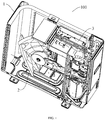
FIG. 1 is a perspective view of an air conditioner according to embodiments of the present disclosure. -
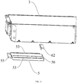
FIG. 2 is an exploded view of a welded member for electronic control, a waterproof member, and a baffle according to embodiments of the present disclosure. -
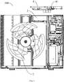
FIG. 3 is a top view of a welded member for electronic control, a waterproof member, and a baffle according to embodiments of the present disclosure. -
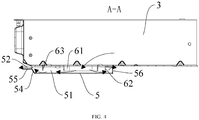
FIG. 4 is sectional view taken along line A-A inFIG. 3 , showing a direction along which air flows. -
FIG. 5 is a front view of an outer unit for an air conditioner according to embodiments of the present disclosure. -
FIG. 6 is a sectional view of a welded member for electronic control, a waterproof member, and a baffle inFIG. 5 , showing a direction along which water drops are splashed. - Reference numerals:
- 100: outdoor unit for air conditioner;
- 1: body; 2: rotor;
- 3: welded member for electronic control; 31: first opening; 32: second opening;
- 4: electronic control component; 41: electronic control element;
- 5: waterproof member; 51: airflow passage; 52: airflow outlet;
- 53: connecting part; 54: incline part; 55: flange; 56: extending part;
- 61: first sub-baffle; 62: second sub-baffle: 63: third sub-baffle.
- Embodiments of the present disclosure are described in detail, and examples of the embodiments are depicted in the drawings. The same or similar elements and the elements having same or similar functions are denoted by like reference numerals throughout the descriptions. The embodiments described herein with reference to drawings are explanatory and only used to illustrate the present disclosure. The embodiments shall not be construed to limit the present disclosure.
- In the description of the present disclosure, it should be understood that, terms such as "central," "longitudinal," "lateral," "length," "width," "thickness," "upper," "lower," "front," "rear," "left," "right," "vertical," "horizontal," "top," "bottom," "inner," "outer," "clockwise," and "counterclockwise," "axial," "radial," "circumferential", etc. should be construed to refer to the orientation and position relationship as then described or as shown in the drawings under discussion for simplifying the description of the present disclosure, but do not alone indicate or imply that the device or element referred to must have a particular orientation. Moreover, it is not required that the present disclosure is constructed or operated in a particular orientation, and shall not be construed to limit the present disclosure. In addition, the feature defined with "first" and "second" may indicate or imply that one or more of these features are provided. In the description of the present disclosure, the term "a plurality of' means two or more than two, unless specified otherwise.
- In the description of the present disclosure, it should be understood that, unless specified or limited otherwise, the terms "mounted," "connected," and "coupled" are used broadly and may be such as fixed connections, detachable connections, or integral connections; may also be mechanical or electrical connections; may also be direct connections or indirect connections via intervening structures; may also be inner communications of two elements, which can be understood by those skilled in the art according to specific situations.
- An outdoor unit for an
air conditioner 100 according to embodiments of the present disclosure is described referring toFIG. 1 to FIG. 6 . The outdoor unit for anair conditioner 100 can be a small multi-coupled-side-air-output outdoor unit. In the following description of the present disclosure, the small multi-coupled-side-air-output outdoor unit will be described as an example of the outdoor unit for anair conditioner 100. Certainly, one of ordinary skill in the art can understand that the outdoor unit for anair conditioner 100 can be other types of an outdoor unit for anair conditioner 100, and not limited to the small multi-coupled-side-air-output outdoor unit. - As illustrated in
FIG. 1-FIG 6 , the outdoor unit for anair conditioner 100 according to embodiments in a first aspect of the present application, such as the small multi-coupled-side-air-output outdoor unit, includes a body 1, arotor 2, a welded member forelectronic control 3, awaterproof member 5, and at least one baffle. - The
rotor 2, the welded member forelectronic control 3, thewaterproof member 5, and the at least one baffle are all arranged in the body 1. Specifically, referring toFIG. 1 andFIG. 5 , the welded member forelectronic control 3 is arranged at a top portion within the body 1, and the welded member forelectronic control 3 is located above therotor 2. The welded member forelectronic control 3 defines at least one opening in a bottom portion, and theelectronic control component 4 is arranged in the welded member forelectronic control 3. For example, in examples shown inFIG. 2 andFIG. 3 , the welded member forelectronic control 3 is in a shape of a substantial rectangle, and the welded member forelectronic control 3 is open at a top portion and a right wall, such that theelectronic control component 4 is mounted in the welded member forelectronic control 3 from the upper to the lower. The opening runs through the bottom portion of the welded member forelectronic control 3 in an up-down direction. Theelectronic control component 4 is provided with anelectronic control element 41. - The waterproof member 5is connected to the bottom portion of the welded member for
electronic control 3, and thewaterproof member 5 is opposite to the opening. Thewaterproof member 5 and the welded member forelectronic control 3 cooperatively define anairflow passage 51 in communication with the opening, two ends (a left end and a right end inFIG. 4 , e.g.) of thewaterproof member 5 are separately spaced apart from the welded member forelectronic control 3 to define twoairflow outlets 52 in communication with theairflow passage 51. As illustrated inFIG. 1 andFIG. 4 , when therotor 2 rotates (clockwise rotates, e.g.), air in the welded member forelectronic control 3 can flow through the opening in the bottom portion of the welded member forelectronic control 3, passes through theairflow passage 51 defined by the welded member forelectronic control 3 and thewaterproof member 5, and reaches at a side with therotor 2 through the twoairflow outlets 52 at two ends of thewaterproof member 5, thereby carrying heat generated by theelectronic control component 4 in the welded member forelectronic control 3 during operation off. Therefore, with the twoairflow outlets 52, heat generated by theelectronic control component 4 during operation can quickly flow to therotor 2 in quantity through the twoairflow outlets 52, achieving quick ventilation and heat dissipation for theelectronic control component 4. - Furthermore, with the arrangement that the
waterproof member 5 is opposite the opening in the bottom portion of the welded member forelectronic control 3, thewaterproof member 5 shields the opening. For example, in case that therotor 2 throws water, since thewaterproof member 5 shields the opening in the bottom portion of the welded member forelectronic control 3, water drops hardly comes into the welded member forelectronic control 3 through the opening, guaranteeing normal operation of theelectronic control component 4. - The baffle is arranged in the
airflow passage 51 to prevent liquid from entering the welded member forelectronic control 3 through theairflow passage 51. When therotor 2 throws water, as illustrated inFIG. 5 andFIG. 6 , with the baffle in theairflow passage 51, even water drops can enter theairflow passage 51 through theairflow outlets 52, the water drops hardly enter the welded member forelectronic control 3 because of prevention by the baffle, thereby further guaranteeing the normal operation of theelectronic control component 4. - In the outdoor unit for an
air conditioner 100 according to embodiments of the present disclosure, such as the small multi-coupled-side-air-output outdoor unit, thewaterproof member 5 is arranged at the bottom portion of the electrically controlled weldedmember 3 and opposite the opening, thewaterproof member 5 and the welded member forelectronic control 3 cooperatively define theairflow passage 51 in communication with the opening and the twoairflow outlets 52 in communication with theairflow passage 51, and the baffle is arranged in theairflow passage 51, quick heat dissipation for theelectronic control component 4 can be realized, and water and the like hardly enter the welded member forelectronic control 3 through the opening, such that theelectronic control component 4 in the welded member forelectronic control 3 can normally operate. - According to some specific embodiments of the present disclosure, referring to
FIG. 2 , thewaterproof member 5 is open at a top portion, two sides of thewaterproof member 5 in a width direction are provided with connectingparts 53 respectively, and the connectingparts 53 extending outwards. Thewaterproof member 5 is connected to the bottom portion of the welded member forelectronic control 3 by means of the connectingparts 53. Two ends (a left end and a right end inFIG. 2 , e.g.) of thewaterproof member 5 in a length direction are spaced apart from the welded member forelectronic control 3 to define the twoairflow outlets 52 respectively. For example, in the example inFIG. 2 , each of the connectingparts 53 can extend outwards from a top edge of thewaterproof member 5 in the width direction, the connectingparts 53 can be connected to the bottom portion of the welded member forelectronic control 3 by means of screws, etc., such that thewaterproof member 5 can be conveniently and firmly connected to the bottom portion of the welded member forelectronic control 3 by means of the connectingparts 53. It should be noted herein, a direction "out" can be understood as a direction way from a center of thewaterproof member 5, and an opposite direction is defined as "in", i.e. a direction towards the center of thewaterproof member 5. Top surfaces of two ends of thewaterproof member 5 in the length direction can be both lower than top surfaces of the two ends of thewaterproof member 5 in the width direction, such that the two ends of thewaterproof member 5 in the length direction can be spaced apart from the welded member forelectronic control 3 to define the twoairflow outlets 52 respectively. Therefore, thewaterproof member 5 is simple in whole structure, easy to realize, and low in cost. Connection between the waterproof member and the welded member forelectronic control 3 is convenient. - Optionally, as shown in
FIG. 2-FIG 4 , at least one of the two ends of thewaterproof member 5 in the length direction is provided with anincline part 54, and theincline part 54 obliquely extends upwards in the direction away from the center of thewaterproof member 5. Theincline part 54 has a free end (a left end inFIG. 4 , e.g.), and the free end is provided with aflange 55 horizontally extending outwards, an upper surface of theflange 55 is spaced apart from the bottom portion of the welded member forelectronic control 3 to define theairflow outlet 52. For example, referring toFIG. 2 andFIG. 3 as well asFIG. 4 , theincline part 54 obliquely extends upwards from a left end of thewaterproof member 5, theflange 55 horizontally extends leftwards from a left end of theincline part 54. Therefore, with theincline part 54 and theflange 55, compared with a bottom wall of thewaterproof member 5, theincline part 54 and theflange 55 are kept at smaller distances from the bottom portion of the welded member forelectronic control 3. On the premise that air can smoothly pass through theairflow passage 51 and flow out through theairflow outlet 52, water and the like on therotor 2 more hardly enter thewaterproof member 5 through theairflow outlet 52, achieving a comparatively waterproof effect of thewaterproof member 5. - Or optionally, as shown in
FIG. 2-FIG. 4 , at least one of the two ends of thewaterproof member 5 in the length direction is provided with an extendingpart 56 vertically extending upwards. A top surface of the extendingpart 56 is spaced apart from the bottom portion of the welded member forelectronic control 3 to define theairflow outlet 52. A distance between the top surface of the extendingpart 56 and the bottom portion of the welded member forelectronic control 3 is less than a distance between the bottom wall of thewaterproof member 5 and the bottom portion of the welded member forelectronic control 3. Therefore, on the premise that air can smoothly pass through theairflow passage 51 and flow out through theairflow outlet 52, water and the like on therotor 2 also more hardly enter thewaterproof member 5 through theairflow outlet 52, also achieving a comparatively waterproof effect of thewaterproof member 5. For example, referring toFIG. 2 andFIG. 3 as well asFIG. 4 , the extendingpart 56 vertically extend upwards from a left end of thewaterproof member 5, and the two ends of the extendingpart 56 in the length direction can extend to be in contact with two side walls of thewaterproof member 5 in the width direction respectively, for a better waterproof effect. - It should be noted that, in examples in
FIG. 2 to FIG. 4 andFIG. 6 , one end of thewaterproof member 5 in the length direction is provided with theincline part 54 and theflange 55, and the other end is provided with the extendingpart 56, in order to guarantee good ventilation and heat dissipation, as well as achieve the better waterproof effect. Certainly, the present disclosure is not limited thereto, each the two ends of thewaterproof member 5 in the length direction can provided with theincline part 54 and theflange 55, or the extending part 56 (not shown in the drawings). It should be noted that, specific structures of the two ends of thewaterproof member 5 in the length direction can be configured according to actually needs for better satisfying actual applications. - Optionally, referring to
FIG. 6 , a width of theairflow outlet 52 in an up-down direction is represented by a, a is greater than 0 mm and less than or equal to 10 mm. Therefore, when the width a of theairflow outlet 52 is greater than 10 mm, though heat of theelectronic control component 4 can be carried out quickly, a risk that the water the like on therotor 2 enter thewaterproof member 5 through theairflow outlet 52 is large due to a large distance between ends of thewaterproof member 5 in the length direction and the welded member forelectronic control 3. In other words, by setting the width a of theairflow outlet 52 to fulfill 0<a≤10mm, on the premise of good ventilation and heat dissipation for theelectronic control component 4, water and the like on therotor 2 hardly enter thewaterproof member 5 through theairflow outlet 52, thereby guaranteeing reliable operation of theelectronic control component 4. - According to further embodiments of the present disclosure, as shown in
FIG. 3 ,FIG. 4 , andFIG. 6 , the baffle includes a first sub-baffle 61, the first sub-baffle 61 surrounds the opening and extends downwards into thewaterproof member 5. For example, referring toFIG. 3 ,FIG. 4 , andFIG. 6 , the opening is a substantial rectangular opening, the first sub-baffle 61 can be an annular baffle plate. The first sub-baffle 61 has an upper end connected to a side wall defining the opening, and a lower end vertically extending downwards and spaced apart from the bottom wall of thewaterproof member 5. Therefore, with the above first sub-baffle 61, on the premise that the heat can be smoothly discharged, water drops entering theairflow passage 51 can be further stopped. - Furthermore, referring to
FIG. 2 ,FIG. 4 andFIG. 6 , the baffle further includes a second sub-baffle 62, the second sub-baffle 62 has a first end connected to the bottom portion of the electrically controlled weldedmember 3 and a second end extending downwards and spaced apart from the bottom wall of thewaterproof member 5. The second sub-baffle 62 is arranged between the opening and theairflow outlet 52. For example, in examples ofFIG. 2 ,FIG. 4 , andFIG. 6 , the second sub-baffle 62 is arranged between the first sub-baffle 61 and theairflow outlet 52 at a right side of thewaterproof member 5. The second sub-baffle 62 is substantially L-shaped. Specifically, the second sub-baffle 62 includes a connecting plate horizontally extending and connected to the bottom portion of the welded member forelectronic control 3, and a baffle part having a first end connected to the connecting plate and a second send vertically extending downwards. A lower end surface of the baffle part is spaced apart from a bottom wall of thewaterproof member 5. Therefore, with the second sub-baffle 62, after water drops enter theairflow passage 51 through theairflow outlet 52 at the right side, firstly the second sub-baffle 62 stops the water drops. If some water droops can pass through the second sub-baffle 62, all the water drops can be substantially stopped at the first sub-baffle 61. - Furthermore, as shown in
FIG. 3 ,FIG. 4 , andFIG. 6 , the opening includes afirst orifice 31 and asecond orifice 32 spaced apart from each other. The first sub-baffle 61 is connected at thefirst orifice 31. Thesecond orifice 32 is located at a side of thefirst orifice 31 away from thesecond sub-baffle 62. A third sub-baffle 63 is arranged at thesecond orifice 32, and the third sub-baffle 63 is connected to a side wall of thesecond orifice 32 away from the first sub-baffle 61. For example, in examples inFIG. 3 ,FIG. 4 , andFIG. 6 , the third sub-baffle 63 is arranged between theairflow outlet 52 of thewaterproof member 5 at the left side and the first sub-baffle 61, and the third sub-baffle 63 vertically extends downwards from a left side wall of thesecond orifice 32. Therefore, after water drops enter theairflow passage 51 through theairflow outlet 52 at the left side, firstly, the third sub-baffle 63 stops the water drops. If some water drops can pass through the third sub-baffle 63, all the water drops can also be substantially stopped at the first sub-baffle 61. - Therefore, with the above first sub-baffle 61, second sub-baffle, and third sub-baffle 63, a barrier of two layers can be achieved, water thrown from the
rotor 2 hardly enters the welded member forelectronic control 3 through the opening, thereby guaranteeing reliable operation of theelectronic control component 4 in a long term. - Optionally, as shown in
FIG. 6 , the width of theairflow outlet 52 in the up-down direction is represented by a, a height of the first sub-baffle 61 is represented by b, a height of the second sub-baffle 62 is represented by c, and a distance between a bottom surface of the welded member forelectronic control 3 and the bottom wall of thewaterproof member 5 is represented by d, a, b, c, and d fulfill d≥a, a<b<d, and a<c<d. Therefore, by setting the width a of theairflow outlet 52 less than or equal to the distance d, water from outside hardly enters thewaterproof member 5 through theairflow outlet 52. By setting the height b of the first sub-baffle 61 and the height c of the second sub-baffle 62 between the width a of theairflow outlet 52 and the distance d, on the premise that the stopping effect is guaranteed, heat generated during operation of theelectronic control component 4 can be smoothly discharged. It should be noted that, Specific values of the above dimensions can be determined according to actual structure of the outdoor unit for anair conditioner 100. - According to some embodiments of the present disclosure, the
electronic control component 4 is inverted in the welded member forelectronic control 3. For example, in an example inFIG. 5 , theelectronic control element 41 is arranged at a lower surface of theelectronic control component 4. During assembling, theelectronic control component 4 is inverted and mounted to an upper portion of the body 1. Specifically, theelectronic control component 4 can be mounted in the welded member forelectronic control 3 from the upper to the lower. - The air conditioner according to embodiments of a second aspect of the present disclosure includes the outdoor unit for an
air conditioner 100 according to embodiments of the first aspect of the present disclosure. - The whole performance of the air conditioner according to embodiments of the present disclosure can be improved with the outdoor unit for an
air conditioner 100. - Other configurations and operations of the air conditioner according to embodiments of the present disclosure are known to those skilled in the art, which will not described in detail herein.
- Throughout the description of the present disclosure, reference to "an embodiment," "some embodiments," "explanatory embodiment", "an example," "a specific example," or "some examples," means that a particular feature, structure, material, or characteristic described in connection with the embodiment or example is included in at least one embodiment or example of the present disclosure. Thus, the appearances of the phrases in various places throughout this specification are not necessarily referring to the same embodiment or example of the present disclosure. Furthermore, the particular features, structures, materials, or characteristics may be combined in any suitable manner in one or more embodiments or examples.
- Although explanatory embodiments have been shown and described, it would be appreciated by those skilled in the art that the above embodiments cannot be construed to limit the present disclosure, and changes, alternatives, and modifications can be made in the embodiments without departing from spirit, principles and scope of the present disclosure.
Claims (11)
- An outdoor unit for an air conditioner, comprising:a body;a rotor arranged in the body;a welded member for electronic control arranged in a top portion within the body, defining at least one opening in a bottom portion of the welded member for electronic control, and provided with an electronic control component in the welded member for electronic control;a waterproof member connected to the bottom portion of the welded member for electronic control and being opposite to the opening, the waterproof member defining an airflow passage in communication with the opening cooperatively with the welded member for electronic control, the waterproof member having two ends separately spaced apart from the welded member for electronic control to define two airflow outlets in communication with the airflow passage; andat least one baffle arranged in the airflow passage to prevent liquid from entering the welded member for electronic control through the airflow passage.
- The outdoor unit according to claim 1, wherein the waterproof member is open at a top portion, two sides of the waterproof member in a width direction are provided with connecting parts extending outwards respectively, the waterproof member is connected to the bottom portion of the welded member for electronic control by means of the connecting parts, and two ends of the waterproof member in the length direction are spaced apart from the welded member for electronic control to define the two airflow outlets respectively.
- The outdoor unit according to claim 2, wherein at least one end of the two ends of the waterproof member in the length direction is provided with an incline part, the incline part obliquely extends upwards in a direction away from a center of the waterproof member and has a free end, the free end of the incline part is provided with a flange horizontally extending outwards, an upper surface of the flange is spaced apart from the bottom portion of the welded member for electronic control to define the airflow outlet.
- The outdoor unit according to claim 2, wherein at least one end of the two ends of the waterproof member in the length direction is provided with an extending part vertically extending upwards, and a top surface of the extending part is spaced apart from the bottom portion of the welded member for electronic control to define the airflow outlet.
- The outdoor unit according to claim 2, wherein a width of the airflow outlet in an up-down direction is represented by a, and the a fulfills 0<a≤10mm.
- The outdoor unit according to any one of claims 1 to 5, wherein the baffle comprises a first sub-baffle, and the first sub-baffle surrounds the opening and extends downwards into the waterproof member.
- The outdoor unit according to claim 6, wherein the baffle further comprises a second sub-baffle, the second sub-baffle plate has a first end connected to the bottom portion of the welded member for electronic control and a second end extending downwards and spaced apart from a bottom wall of the waterproof member, and the second sub-baffle plate is arranged between the opening and the airflow outlet.
- The outdoor unit according to claim 7, wherein the opening comprises a first orifice and a second orifice spaced apart from each other, the first sub-baffle is connected at the first orifice, the second orifice is located at a side of the first orifice away from the second sub-baffle plate, the third sub-baffle is arranged at the second orifice, and the third sub-baffle is connected to a side wall of the second orifice away from the first sub-baffle.
- The outdoor unit according to claim 7, wherein a width of the airflow outlet in an up-down direction is represented by a, a height of the first sub-baffle is represented by b, a height of the second sub-baffle is represented by c, a distance between a bottom surface of the welded member for electronic control and a bottom wall of the waterproof member is represented by d, and a, b, c, and d fulfill d≥a, a<b<d, and a<c<d.
- The outdoor unit according to any one of claims 1 to 9, wherein the electronic control component is inverted in the welded member for electronic control.
- An air conditioner, comprising the outdoor unit according to any one of claims 1 to 10.
Applications Claiming Priority (3)
| Application Number | Priority Date | Filing Date | Title |
|---|---|---|---|
| CN201821480814.XU CN208804791U (en) | 2018-09-10 | 2018-09-10 | Air-conditioner outdoor unit and air conditioner with it |
| CN201811051438.7A CN109084380A (en) | 2018-09-10 | 2018-09-10 | Air-conditioner outdoor unit and air conditioner with it |
| PCT/CN2019/089862 WO2020052280A1 (en) | 2018-09-10 | 2019-06-03 | Air conditioning outdoor unit and air conditioner having same |
Publications (4)
| Publication Number | Publication Date |
|---|---|
| EP3650765A1 true EP3650765A1 (en) | 2020-05-13 |
| EP3650765A4 EP3650765A4 (en) | 2020-07-22 |
| EP3650765C0 EP3650765C0 (en) | 2023-12-06 |
| EP3650765B1 EP3650765B1 (en) | 2023-12-06 |
Family
ID=69630628
Family Applications (1)
| Application Number | Title | Priority Date | Filing Date |
|---|---|---|---|
| EP19812898.5A Active EP3650765B1 (en) | 2018-09-10 | 2019-06-03 | Air conditioning outdoor unit and air conditioner having same |
Country Status (3)
| Country | Link |
|---|---|
| EP (1) | EP3650765B1 (en) |
| KR (1) | KR20200032037A (en) |
| WO (1) | WO2020052280A1 (en) |
Cited By (1)
| Publication number | Priority date | Publication date | Assignee | Title |
|---|---|---|---|---|
| US11802696B2 (en) | 2019-08-01 | 2023-10-31 | Mitsubishi Electric Corporation | Outdoor unit for air-conditioning apparatus and air-conditioning apparatus |
Family Cites Families (12)
| Publication number | Priority date | Publication date | Assignee | Title |
|---|---|---|---|---|
| JP2008281286A (en) * | 2007-05-11 | 2008-11-20 | Hitachi Appliances Inc | Air conditioner outdoor unit |
| CN203810585U (en) * | 2014-05-20 | 2014-09-03 | 广东美的暖通设备有限公司 | Electric control box and air conditioner comprising same |
| CN204244638U (en) * | 2014-12-26 | 2015-04-01 | 宁波奥克斯电气有限公司 | Heat dissipation and waterproof structure of air conditioner electric control box |
| KR102283905B1 (en) * | 2014-12-30 | 2021-08-02 | 엘지전자 주식회사 | Outdoor unit of air conditioiner |
| CN106440101A (en) * | 2016-11-07 | 2017-02-22 | 广东美的制冷设备有限公司 | Outdoor unit of air conditioner and air conditioner |
| CN206226868U (en) * | 2016-11-24 | 2017-06-06 | 广东美的暖通设备有限公司 | Electric-controlled box and the air-conditioner with it |
| CN106765674A (en) * | 2017-01-19 | 2017-05-31 | 芜湖美智空调设备有限公司 | Automatically controlled radiator structure and air-conditioning equipment |
| CN207113183U (en) * | 2017-06-06 | 2018-03-16 | 广东美的暖通设备有限公司 | The electric cabinet and air conditioner of air conditioner |
| CN207146710U (en) * | 2017-08-28 | 2018-03-27 | 广东美的制冷设备有限公司 | Baffle arrangement, electric-controlled box, air-conditioner outdoor unit and air conditioner |
| CN108050610A (en) * | 2017-12-08 | 2018-05-18 | Tcl空调器(中山)有限公司 | Automatically controlled box and air condensing units |
| CN208804791U (en) * | 2018-09-10 | 2019-04-30 | 广东美的暖通设备有限公司 | Air-conditioner outdoor unit and air conditioner with it |
| CN109084380A (en) * | 2018-09-10 | 2018-12-25 | 广东美的暖通设备有限公司 | Air-conditioner outdoor unit and air conditioner with it |
-
2019
- 2019-06-03 KR KR1020197035506A patent/KR20200032037A/en not_active Withdrawn
- 2019-06-03 WO PCT/CN2019/089862 patent/WO2020052280A1/en not_active Ceased
- 2019-06-03 EP EP19812898.5A patent/EP3650765B1/en active Active
Cited By (1)
| Publication number | Priority date | Publication date | Assignee | Title |
|---|---|---|---|---|
| US11802696B2 (en) | 2019-08-01 | 2023-10-31 | Mitsubishi Electric Corporation | Outdoor unit for air-conditioning apparatus and air-conditioning apparatus |
Also Published As
| Publication number | Publication date |
|---|---|
| EP3650765C0 (en) | 2023-12-06 |
| KR20200032037A (en) | 2020-03-25 |
| WO2020052280A1 (en) | 2020-03-19 |
| EP3650765A4 (en) | 2020-07-22 |
| EP3650765B1 (en) | 2023-12-06 |
Similar Documents
| Publication | Publication Date | Title |
|---|---|---|
| EP3288355B1 (en) | Housing for electronic devices including air outlet with fluid ingress mitigation | |
| JP6423552B2 (en) | Electronic control unit | |
| KR102927717B1 (en) | Electrical control box, air conditioner outdoor unit and air conditioner | |
| EP3650765B1 (en) | Air conditioning outdoor unit and air conditioner having same | |
| CN118031301A (en) | Indoor unit and heating ventilation equipment | |
| CN217979205U (en) | Outdoor unit and air conditioner | |
| CN108844144A (en) | Electrical box and air conditioner | |
| CN109084383B (en) | Air conditioner outdoor unit and air conditioner having the same | |
| US20150342086A1 (en) | Cooling device, and heating element housing device equipped with same | |
| CN203375566U (en) | Air conditioner outdoor unit and air conditioner with air conditioner outdoor unit | |
| CN109564013B (en) | Outdoor unit of air conditioner | |
| CN210490203U (en) | Power distribution cabinet convenient for heat dissipation | |
| CN205783589U (en) | For the electrically-controlled component of air-conditioner and the air-conditioner with it | |
| CN209448251U (en) | Electric cabinet | |
| CN218163135U (en) | Outer machine of heat pump and heat pump equipment | |
| US20250216096A1 (en) | Air Conditioner Outdoor Unit and Air Conditioning Device | |
| CN111811046A (en) | Indoor unit and air conditioner with same | |
| CN111315167A (en) | Automatically controlled box and outdoor refrigeration mechanism | |
| CN109084380A (en) | Air-conditioner outdoor unit and air conditioner with it | |
| CN111536601B (en) | Waterproof structure of outdoor unit of air conditioner and air conditioner | |
| EP4411258A1 (en) | Heat exchanger sealing plate for air conditioner, indoor unit and air conditioner | |
| CN211345557U (en) | Temperature adjusting module of air conditioner and air conditioner with same | |
| CN215991691U (en) | Air-cooled heat dissipation display | |
| CN105703525B (en) | Motor and vehicle with same | |
| CN112432251B (en) | Outdoor machine of air conditioner |
Legal Events
| Date | Code | Title | Description |
|---|---|---|---|
| STAA | Information on the status of an ep patent application or granted ep patent |
Free format text: STATUS: UNKNOWN |
|
| STAA | Information on the status of an ep patent application or granted ep patent |
Free format text: STATUS: THE INTERNATIONAL PUBLICATION HAS BEEN MADE |
|
| PUAI | Public reference made under article 153(3) epc to a published international application that has entered the european phase |
Free format text: ORIGINAL CODE: 0009012 |
|
| STAA | Information on the status of an ep patent application or granted ep patent |
Free format text: STATUS: REQUEST FOR EXAMINATION WAS MADE |
|
| 17P | Request for examination filed |
Effective date: 20191210 |
|
| AK | Designated contracting states |
Kind code of ref document: A1 Designated state(s): AL AT BE BG CH CY CZ DE DK EE ES FI FR GB GR HR HU IE IS IT LI LT LU LV MC MK MT NL NO PL PT RO RS SE SI SK SM TR |
|
| AX | Request for extension of the european patent |
Extension state: BA ME |
|
| A4 | Supplementary search report drawn up and despatched |
Effective date: 20200622 |
|
| RIC1 | Information provided on ipc code assigned before grant |
Ipc: F24F 1/24 20110101AFI20200616BHEP Ipc: F24F 1/48 20110101ALI20200616BHEP Ipc: F24F 1/22 20110101ALI20200616BHEP |
|
| RIN1 | Information on inventor provided before grant (corrected) |
Inventor name: ZHANG, HAO Inventor name: WANG, PENG Inventor name: YI, TENGDA Inventor name: HUANG, JIN |
|
| DAV | Request for validation of the european patent (deleted) | ||
| DAX | Request for extension of the european patent (deleted) | ||
| STAA | Information on the status of an ep patent application or granted ep patent |
Free format text: STATUS: EXAMINATION IS IN PROGRESS |
|
| 17Q | First examination report despatched |
Effective date: 20220317 |
|
| GRAP | Despatch of communication of intention to grant a patent |
Free format text: ORIGINAL CODE: EPIDOSNIGR1 |
|
| STAA | Information on the status of an ep patent application or granted ep patent |
Free format text: STATUS: GRANT OF PATENT IS INTENDED |
|
| INTG | Intention to grant announced |
Effective date: 20230720 |
|
| GRAS | Grant fee paid |
Free format text: ORIGINAL CODE: EPIDOSNIGR3 |
|
| GRAA | (expected) grant |
Free format text: ORIGINAL CODE: 0009210 |
|
| STAA | Information on the status of an ep patent application or granted ep patent |
Free format text: STATUS: THE PATENT HAS BEEN GRANTED |
|
| AK | Designated contracting states |
Kind code of ref document: B1 Designated state(s): AL AT BE BG CH CY CZ DE DK EE ES FI FR GB GR HR HU IE IS IT LI LT LU LV MC MK MT NL NO PL PT RO RS SE SI SK SM TR |
|
| REG | Reference to a national code |
Ref country code: GB Ref legal event code: FG4D |
|
| REG | Reference to a national code |
Ref country code: DE Ref legal event code: R096 Ref document number: 602019042923 Country of ref document: DE |
|
| REG | Reference to a national code |
Ref country code: CH Ref legal event code: EP |
|
| REG | Reference to a national code |
Ref country code: IE Ref legal event code: FG4D |
|
| U01 | Request for unitary effect filed |
Effective date: 20240102 |
|
| U07 | Unitary effect registered |
Designated state(s): AT BE BG DE DK EE FI FR IT LT LU LV MT NL PT SE SI Effective date: 20240111 |
|
| PG25 | Lapsed in a contracting state [announced via postgrant information from national office to epo] |
Ref country code: GR Free format text: LAPSE BECAUSE OF FAILURE TO SUBMIT A TRANSLATION OF THE DESCRIPTION OR TO PAY THE FEE WITHIN THE PRESCRIBED TIME-LIMIT Effective date: 20240307 |
|
| PG25 | Lapsed in a contracting state [announced via postgrant information from national office to epo] |
Ref country code: ES Free format text: LAPSE BECAUSE OF FAILURE TO SUBMIT A TRANSLATION OF THE DESCRIPTION OR TO PAY THE FEE WITHIN THE PRESCRIBED TIME-LIMIT Effective date: 20231206 |
|
| PG25 | Lapsed in a contracting state [announced via postgrant information from national office to epo] |
Ref country code: GR Free format text: LAPSE BECAUSE OF FAILURE TO SUBMIT A TRANSLATION OF THE DESCRIPTION OR TO PAY THE FEE WITHIN THE PRESCRIBED TIME-LIMIT Effective date: 20240307 Ref country code: ES Free format text: LAPSE BECAUSE OF FAILURE TO SUBMIT A TRANSLATION OF THE DESCRIPTION OR TO PAY THE FEE WITHIN THE PRESCRIBED TIME-LIMIT Effective date: 20231206 |
|
| PG25 | Lapsed in a contracting state [announced via postgrant information from national office to epo] |
Ref country code: RS Free format text: LAPSE BECAUSE OF FAILURE TO SUBMIT A TRANSLATION OF THE DESCRIPTION OR TO PAY THE FEE WITHIN THE PRESCRIBED TIME-LIMIT Effective date: 20231206 Ref country code: NO Free format text: LAPSE BECAUSE OF FAILURE TO SUBMIT A TRANSLATION OF THE DESCRIPTION OR TO PAY THE FEE WITHIN THE PRESCRIBED TIME-LIMIT Effective date: 20240306 Ref country code: HR Free format text: LAPSE BECAUSE OF FAILURE TO SUBMIT A TRANSLATION OF THE DESCRIPTION OR TO PAY THE FEE WITHIN THE PRESCRIBED TIME-LIMIT Effective date: 20231206 |
|
| PG25 | Lapsed in a contracting state [announced via postgrant information from national office to epo] |
Ref country code: IS Free format text: LAPSE BECAUSE OF FAILURE TO SUBMIT A TRANSLATION OF THE DESCRIPTION OR TO PAY THE FEE WITHIN THE PRESCRIBED TIME-LIMIT Effective date: 20240406 |
|
| PG25 | Lapsed in a contracting state [announced via postgrant information from national office to epo] |
Ref country code: CZ Free format text: LAPSE BECAUSE OF FAILURE TO SUBMIT A TRANSLATION OF THE DESCRIPTION OR TO PAY THE FEE WITHIN THE PRESCRIBED TIME-LIMIT Effective date: 20231206 |
|
| PG25 | Lapsed in a contracting state [announced via postgrant information from national office to epo] |
Ref country code: SK Free format text: LAPSE BECAUSE OF FAILURE TO SUBMIT A TRANSLATION OF THE DESCRIPTION OR TO PAY THE FEE WITHIN THE PRESCRIBED TIME-LIMIT Effective date: 20231206 |
|
| PG25 | Lapsed in a contracting state [announced via postgrant information from national office to epo] |
Ref country code: SM Free format text: LAPSE BECAUSE OF FAILURE TO SUBMIT A TRANSLATION OF THE DESCRIPTION OR TO PAY THE FEE WITHIN THE PRESCRIBED TIME-LIMIT Effective date: 20231206 Ref country code: SK Free format text: LAPSE BECAUSE OF FAILURE TO SUBMIT A TRANSLATION OF THE DESCRIPTION OR TO PAY THE FEE WITHIN THE PRESCRIBED TIME-LIMIT Effective date: 20231206 Ref country code: RO Free format text: LAPSE BECAUSE OF FAILURE TO SUBMIT A TRANSLATION OF THE DESCRIPTION OR TO PAY THE FEE WITHIN THE PRESCRIBED TIME-LIMIT Effective date: 20231206 Ref country code: IS Free format text: LAPSE BECAUSE OF FAILURE TO SUBMIT A TRANSLATION OF THE DESCRIPTION OR TO PAY THE FEE WITHIN THE PRESCRIBED TIME-LIMIT Effective date: 20240406 Ref country code: CZ Free format text: LAPSE BECAUSE OF FAILURE TO SUBMIT A TRANSLATION OF THE DESCRIPTION OR TO PAY THE FEE WITHIN THE PRESCRIBED TIME-LIMIT Effective date: 20231206 |
|
| U20 | Renewal fee for the european patent with unitary effect paid |
Year of fee payment: 6 Effective date: 20240624 |
|
| PG25 | Lapsed in a contracting state [announced via postgrant information from national office to epo] |
Ref country code: PL Free format text: LAPSE BECAUSE OF FAILURE TO SUBMIT A TRANSLATION OF THE DESCRIPTION OR TO PAY THE FEE WITHIN THE PRESCRIBED TIME-LIMIT Effective date: 20231206 |
|
| PG25 | Lapsed in a contracting state [announced via postgrant information from national office to epo] |
Ref country code: PL Free format text: LAPSE BECAUSE OF FAILURE TO SUBMIT A TRANSLATION OF THE DESCRIPTION OR TO PAY THE FEE WITHIN THE PRESCRIBED TIME-LIMIT Effective date: 20231206 |
|
| REG | Reference to a national code |
Ref country code: DE Ref legal event code: R097 Ref document number: 602019042923 Country of ref document: DE |
|
| PLBE | No opposition filed within time limit |
Free format text: ORIGINAL CODE: 0009261 |
|
| STAA | Information on the status of an ep patent application or granted ep patent |
Free format text: STATUS: NO OPPOSITION FILED WITHIN TIME LIMIT |
|
| 26N | No opposition filed |
Effective date: 20240909 |
|
| PG25 | Lapsed in a contracting state [announced via postgrant information from national office to epo] |
Ref country code: MC Free format text: LAPSE BECAUSE OF FAILURE TO SUBMIT A TRANSLATION OF THE DESCRIPTION OR TO PAY THE FEE WITHIN THE PRESCRIBED TIME-LIMIT Effective date: 20231206 |
|
| REG | Reference to a national code |
Ref country code: CH Ref legal event code: PL |
|
| GBPC | Gb: european patent ceased through non-payment of renewal fee |
Effective date: 20240603 |
|
| PG25 | Lapsed in a contracting state [announced via postgrant information from national office to epo] |
Ref country code: IE Free format text: LAPSE BECAUSE OF NON-PAYMENT OF DUE FEES Effective date: 20240603 |
|
| PG25 | Lapsed in a contracting state [announced via postgrant information from national office to epo] |
Ref country code: CH Free format text: LAPSE BECAUSE OF NON-PAYMENT OF DUE FEES Effective date: 20240630 |
|
| PG25 | Lapsed in a contracting state [announced via postgrant information from national office to epo] |
Ref country code: GB Free format text: LAPSE BECAUSE OF NON-PAYMENT OF DUE FEES Effective date: 20240603 |
|
| U20 | Renewal fee for the european patent with unitary effect paid |
Year of fee payment: 7 Effective date: 20250624 |
|
| PG25 | Lapsed in a contracting state [announced via postgrant information from national office to epo] |
Ref country code: CY Free format text: LAPSE BECAUSE OF FAILURE TO SUBMIT A TRANSLATION OF THE DESCRIPTION OR TO PAY THE FEE WITHIN THE PRESCRIBED TIME-LIMIT; INVALID AB INITIO Effective date: 20190603 |
|
| PG25 | Lapsed in a contracting state [announced via postgrant information from national office to epo] |
Ref country code: HU Free format text: LAPSE BECAUSE OF FAILURE TO SUBMIT A TRANSLATION OF THE DESCRIPTION OR TO PAY THE FEE WITHIN THE PRESCRIBED TIME-LIMIT; INVALID AB INITIO Effective date: 20190603 |
|
| U1N | Appointed representative for the unitary patent procedure changed after the registration of the unitary effect |
Representative=s name: TREEBY, PHILIP DAVID WILLIAM; GB |