EP3650723B1 - Shaft coupling structure and telescopic shaft - Google Patents
Shaft coupling structure and telescopic shaft Download PDFInfo
- Publication number
- EP3650723B1 EP3650723B1 EP18841232.4A EP18841232A EP3650723B1 EP 3650723 B1 EP3650723 B1 EP 3650723B1 EP 18841232 A EP18841232 A EP 18841232A EP 3650723 B1 EP3650723 B1 EP 3650723B1
- Authority
- EP
- European Patent Office
- Prior art keywords
- shaft
- axial direction
- concave
- coupling
- joint
- Prior art date
- Legal status (The legal status is an assumption and is not a legal conclusion. Google has not performed a legal analysis and makes no representation as to the accuracy of the status listed.)
- Active
Links
- 230000008878 coupling Effects 0.000 title claims description 93
- 238000010168 coupling process Methods 0.000 title claims description 93
- 238000005859 coupling reaction Methods 0.000 title claims description 93
- 230000002093 peripheral effect Effects 0.000 claims description 135
- 238000003780 insertion Methods 0.000 claims description 35
- 230000037431 insertion Effects 0.000 claims description 35
- 239000011324 bead Substances 0.000 claims description 34
- 239000000428 dust Substances 0.000 claims description 15
- 239000007787 solid Substances 0.000 description 14
- 238000003466 welding Methods 0.000 description 10
- 230000005540 biological transmission Effects 0.000 description 8
- 238000006073 displacement reaction Methods 0.000 description 8
- 239000004033 plastic Substances 0.000 description 8
- 230000007547 defect Effects 0.000 description 7
- 230000000694 effects Effects 0.000 description 5
- 238000004049 embossing Methods 0.000 description 4
- 238000005304 joining Methods 0.000 description 4
- 230000015572 biosynthetic process Effects 0.000 description 3
- 230000033001 locomotion Effects 0.000 description 3
- 238000000926 separation method Methods 0.000 description 3
- 230000008602 contraction Effects 0.000 description 2
- 239000004519 grease Substances 0.000 description 2
- 230000001771 impaired effect Effects 0.000 description 2
- 239000002184 metal Substances 0.000 description 2
- 230000004323 axial length Effects 0.000 description 1
- 238000005336 cracking Methods 0.000 description 1
- 238000010586 diagram Methods 0.000 description 1
- 239000010419 fine particle Substances 0.000 description 1
- 238000005242 forging Methods 0.000 description 1
- 239000000463 material Substances 0.000 description 1
- 230000004048 modification Effects 0.000 description 1
- 238000012986 modification Methods 0.000 description 1
- 230000036316 preload Effects 0.000 description 1
- 239000002994 raw material Substances 0.000 description 1
- 229920003051 synthetic elastomer Polymers 0.000 description 1
- 229920003002 synthetic resin Polymers 0.000 description 1
- 239000000057 synthetic resin Substances 0.000 description 1
- 239000005061 synthetic rubber Substances 0.000 description 1
Images


Classifications
-
- B—PERFORMING OPERATIONS; TRANSPORTING
- B62—LAND VEHICLES FOR TRAVELLING OTHERWISE THAN ON RAILS
- B62D—MOTOR VEHICLES; TRAILERS
- B62D1/00—Steering controls, i.e. means for initiating a change of direction of the vehicle
- B62D1/02—Steering controls, i.e. means for initiating a change of direction of the vehicle vehicle-mounted
- B62D1/16—Steering columns
- B62D1/20—Connecting steering column to steering gear
-
- B—PERFORMING OPERATIONS; TRANSPORTING
- B62—LAND VEHICLES FOR TRAVELLING OTHERWISE THAN ON RAILS
- B62D—MOTOR VEHICLES; TRAILERS
- B62D1/00—Steering controls, i.e. means for initiating a change of direction of the vehicle
- B62D1/02—Steering controls, i.e. means for initiating a change of direction of the vehicle vehicle-mounted
- B62D1/16—Steering columns
- B62D1/18—Steering columns yieldable or adjustable, e.g. tiltable
- B62D1/19—Steering columns yieldable or adjustable, e.g. tiltable incorporating energy-absorbing arrangements, e.g. by being yieldable or collapsible
-
- F—MECHANICAL ENGINEERING; LIGHTING; HEATING; WEAPONS; BLASTING
- F16—ENGINEERING ELEMENTS AND UNITS; GENERAL MEASURES FOR PRODUCING AND MAINTAINING EFFECTIVE FUNCTIONING OF MACHINES OR INSTALLATIONS; THERMAL INSULATION IN GENERAL
- F16C—SHAFTS; FLEXIBLE SHAFTS; ELEMENTS OR CRANKSHAFT MECHANISMS; ROTARY BODIES OTHER THAN GEARING ELEMENTS; BEARINGS
- F16C3/00—Shafts; Axles; Cranks; Eccentrics
- F16C3/02—Shafts; Axles
- F16C3/03—Shafts; Axles telescopic
- F16C3/035—Shafts; Axles telescopic with built-in bearings
-
- F—MECHANICAL ENGINEERING; LIGHTING; HEATING; WEAPONS; BLASTING
- F16—ENGINEERING ELEMENTS AND UNITS; GENERAL MEASURES FOR PRODUCING AND MAINTAINING EFFECTIVE FUNCTIONING OF MACHINES OR INSTALLATIONS; THERMAL INSULATION IN GENERAL
- F16D—COUPLINGS FOR TRANSMITTING ROTATION; CLUTCHES; BRAKES
- F16D1/00—Couplings for rigidly connecting two coaxial shafts or other movable machine elements
- F16D1/02—Couplings for rigidly connecting two coaxial shafts or other movable machine elements for connecting two abutting shafts or the like
- F16D1/027—Couplings for rigidly connecting two coaxial shafts or other movable machine elements for connecting two abutting shafts or the like non-disconnectable, e.g. involving gluing, welding or the like
-
- F—MECHANICAL ENGINEERING; LIGHTING; HEATING; WEAPONS; BLASTING
- F16—ENGINEERING ELEMENTS AND UNITS; GENERAL MEASURES FOR PRODUCING AND MAINTAINING EFFECTIVE FUNCTIONING OF MACHINES OR INSTALLATIONS; THERMAL INSULATION IN GENERAL
- F16C—SHAFTS; FLEXIBLE SHAFTS; ELEMENTS OR CRANKSHAFT MECHANISMS; ROTARY BODIES OTHER THAN GEARING ELEMENTS; BEARINGS
- F16C2326/00—Articles relating to transporting
- F16C2326/20—Land vehicles
- F16C2326/24—Steering systems, e.g. steering rods or columns
-
- F—MECHANICAL ENGINEERING; LIGHTING; HEATING; WEAPONS; BLASTING
- F16—ENGINEERING ELEMENTS AND UNITS; GENERAL MEASURES FOR PRODUCING AND MAINTAINING EFFECTIVE FUNCTIONING OF MACHINES OR INSTALLATIONS; THERMAL INSULATION IN GENERAL
- F16D—COUPLINGS FOR TRANSMITTING ROTATION; CLUTCHES; BRAKES
- F16D1/00—Couplings for rigidly connecting two coaxial shafts or other movable machine elements
- F16D1/02—Couplings for rigidly connecting two coaxial shafts or other movable machine elements for connecting two abutting shafts or the like
- F16D1/04—Couplings for rigidly connecting two coaxial shafts or other movable machine elements for connecting two abutting shafts or the like with clamping hub; with hub and longitudinal key
-
- F—MECHANICAL ENGINEERING; LIGHTING; HEATING; WEAPONS; BLASTING
- F16—ENGINEERING ELEMENTS AND UNITS; GENERAL MEASURES FOR PRODUCING AND MAINTAINING EFFECTIVE FUNCTIONING OF MACHINES OR INSTALLATIONS; THERMAL INSULATION IN GENERAL
- F16D—COUPLINGS FOR TRANSMITTING ROTATION; CLUTCHES; BRAKES
- F16D1/00—Couplings for rigidly connecting two coaxial shafts or other movable machine elements
- F16D1/06—Couplings for rigidly connecting two coaxial shafts or other movable machine elements for attachment of a member on a shaft or on a shaft-end
- F16D1/08—Couplings for rigidly connecting two coaxial shafts or other movable machine elements for attachment of a member on a shaft or on a shaft-end with clamping hub; with hub and longitudinal key
- F16D1/0852—Couplings for rigidly connecting two coaxial shafts or other movable machine elements for attachment of a member on a shaft or on a shaft-end with clamping hub; with hub and longitudinal key with radial clamping between the mating surfaces of the hub and shaft
- F16D1/0864—Couplings for rigidly connecting two coaxial shafts or other movable machine elements for attachment of a member on a shaft or on a shaft-end with clamping hub; with hub and longitudinal key with radial clamping between the mating surfaces of the hub and shaft due to tangential loading of the hub, e.g. a split hub
-
- F—MECHANICAL ENGINEERING; LIGHTING; HEATING; WEAPONS; BLASTING
- F16—ENGINEERING ELEMENTS AND UNITS; GENERAL MEASURES FOR PRODUCING AND MAINTAINING EFFECTIVE FUNCTIONING OF MACHINES OR INSTALLATIONS; THERMAL INSULATION IN GENERAL
- F16D—COUPLINGS FOR TRANSMITTING ROTATION; CLUTCHES; BRAKES
- F16D1/00—Couplings for rigidly connecting two coaxial shafts or other movable machine elements
- F16D1/10—Quick-acting couplings in which the parts are connected by simply bringing them together axially
- F16D2001/103—Quick-acting couplings in which the parts are connected by simply bringing them together axially the torque is transmitted via splined connections
-
- F—MECHANICAL ENGINEERING; LIGHTING; HEATING; WEAPONS; BLASTING
- F16—ENGINEERING ELEMENTS AND UNITS; GENERAL MEASURES FOR PRODUCING AND MAINTAINING EFFECTIVE FUNCTIONING OF MACHINES OR INSTALLATIONS; THERMAL INSULATION IN GENERAL
- F16D—COUPLINGS FOR TRANSMITTING ROTATION; CLUTCHES; BRAKES
- F16D2300/00—Special features for couplings or clutches
- F16D2300/26—Cover or bell housings; Details or arrangements thereof
-
- F—MECHANICAL ENGINEERING; LIGHTING; HEATING; WEAPONS; BLASTING
- F16—ENGINEERING ELEMENTS AND UNITS; GENERAL MEASURES FOR PRODUCING AND MAINTAINING EFFECTIVE FUNCTIONING OF MACHINES OR INSTALLATIONS; THERMAL INSULATION IN GENERAL
- F16D—COUPLINGS FOR TRANSMITTING ROTATION; CLUTCHES; BRAKES
- F16D3/00—Yielding couplings, i.e. with means permitting movement between the connected parts during the drive
- F16D3/02—Yielding couplings, i.e. with means permitting movement between the connected parts during the drive adapted to specific functions
- F16D3/06—Yielding couplings, i.e. with means permitting movement between the connected parts during the drive adapted to specific functions specially adapted to allow axial displacement
- F16D3/065—Yielding couplings, i.e. with means permitting movement between the connected parts during the drive adapted to specific functions specially adapted to allow axial displacement by means of rolling elements
-
- F—MECHANICAL ENGINEERING; LIGHTING; HEATING; WEAPONS; BLASTING
- F16—ENGINEERING ELEMENTS AND UNITS; GENERAL MEASURES FOR PRODUCING AND MAINTAINING EFFECTIVE FUNCTIONING OF MACHINES OR INSTALLATIONS; THERMAL INSULATION IN GENERAL
- F16D—COUPLINGS FOR TRANSMITTING ROTATION; CLUTCHES; BRAKES
- F16D3/00—Yielding couplings, i.e. with means permitting movement between the connected parts during the drive
- F16D3/50—Yielding couplings, i.e. with means permitting movement between the connected parts during the drive with the coupling parts connected by one or more intermediate members
- F16D3/72—Yielding couplings, i.e. with means permitting movement between the connected parts during the drive with the coupling parts connected by one or more intermediate members with axially-spaced attachments to the coupling parts
-
- Y—GENERAL TAGGING OF NEW TECHNOLOGICAL DEVELOPMENTS; GENERAL TAGGING OF CROSS-SECTIONAL TECHNOLOGIES SPANNING OVER SEVERAL SECTIONS OF THE IPC; TECHNICAL SUBJECTS COVERED BY FORMER USPC CROSS-REFERENCE ART COLLECTIONS [XRACs] AND DIGESTS
- Y10—TECHNICAL SUBJECTS COVERED BY FORMER USPC
- Y10T—TECHNICAL SUBJECTS COVERED BY FORMER US CLASSIFICATION
- Y10T403/00—Joints and connections
- Y10T403/47—Molded joint
- Y10T403/472—Molded joint including mechanical interlock
-
- Y—GENERAL TAGGING OF NEW TECHNOLOGICAL DEVELOPMENTS; GENERAL TAGGING OF CROSS-SECTIONAL TECHNOLOGIES SPANNING OVER SEVERAL SECTIONS OF THE IPC; TECHNICAL SUBJECTS COVERED BY FORMER USPC CROSS-REFERENCE ART COLLECTIONS [XRACs] AND DIGESTS
- Y10—TECHNICAL SUBJECTS COVERED BY FORMER USPC
- Y10T—TECHNICAL SUBJECTS COVERED BY FORMER US CLASSIFICATION
- Y10T403/00—Joints and connections
- Y10T403/70—Interfitted members
- Y10T403/7026—Longitudinally splined or fluted rod
- Y10T403/7033—Longitudinally splined or fluted rod including a lock or retainer
Definitions
- the present invention relates to a shaft coupling structure that constitutes a torque transmitting shaft that is assembled in a steering apparatus or the like of an automobile, and relates to a telescopic shaft that includes the torque transmitting shaft and is configured so that the entire length thereof is able to expand or contract in a normal state and/or in a case where an impact load of a specified magnitude or greater is applied in the axial direction.
- FIG. 18 illustrates a steering apparatus for an automobile described in JP 2017-025964A .
- the steering apparatus includes a steering wheel 1, a steering shaft 2, a steering column 3, a pair of universal joints 4a, 4b, an intermediate shaft 5, a steering gear unit 6, and a pair of tie rods 7.
- the steering wheel 1 is attached to a rear end portion of a steering shaft 2 that is rotatably supported inside the steering column 3.
- a front end portion of the steering shaft 2 is connected to an input shaft 8 of the steering gear unit 6 via the pair of universal joints 4a, 4b and the intermediate shaft 5. Then, by converting rotation of the input shaft 8 into a linear motion of a rack (not illustrated), the pair of tie rods 7 are pushed and pulled, and a steering angle corresponding to the operation amount of the steering wheel 1 is applied to steered wheels.
- the front-rear direction refers to the front-rear direction of a vehicle body in which the steering apparatus is assembled.
- a torque transmitting shaft used for transmitting torque such as an intermediate shaft or the like, may be formed by coupling a plurality of shafts.
- a pair of shafts arranged adjacent to each other is coupled by welding so that torque transmission may be performed between the pair of shafts.
- an intermediate shaft is configured by a telescopic shaft in which a pair of shafts is coupled such that the entire length thereof is able to expand or contract in a normal state in which no collision accident has occurred in the vehicle, and/or in a case where a collision accident occurs in the vehicle and a large load that is equal to or greater than a specified value is applied to the intermediate shaft in the axial direction.
- EP 2 039 587 A1 describes a steering apparatus which can ensure the transmission of rotational torque of a steering shaft even when weld joining between a shaft and a shaft coupling is insufficient.
- An extension shaft is inserted from the other end of a joining tubular portion, so that male serrations formed on the extension shaft are brought into engagement with female serrations and a shank portion of the extension shaft is tightly fitted in a fitting hole.
- the other end of the joining tubular portion and an outer circumference of the shank portion of the extension shaft are welded to be joined together, so as to form a weld joining portion.
- a male intermediate shaft is coupled to a shaft coupling which is joined integrally with the extension shaft.
- JP 2002 293 252 A describes a steering shaft which comprises a solid shaft having an outer gear like shaft and a short diameter shaft from a shaft end side, and a hollow shaft having an inner gear like part and calking deforming parts projecting inward at a first position and a second position that are set in the axial direction of the inner gear like part and at a adequate intervals each shorter than the axial length of the outer gear like shaft.
- the calking deforming parts at the first position and the second position of the inner gear like part are engaged with the outer gear like shaft of the solid shaft in a press-pushed state.
- EP 2 735 752 A2 describes a coupling structure for coupling a shaft to a universal joint yoke, wherein an insertion portion of a shaft is passed through an insertion hole of a universal joint yoke. An outward protrusion of a distal end portion of the shaft faces a peripheral edge of a first opening of the insertion hole across a gap in an axial direction. A fixed portion that adjoins the insertion portion is fixed to a peripheral edge of a second opening of the insertion hole by welding.
- An engaging portion formed on an outer periphery of the insertion portion and an engaged portion formed in an inner periphery of the universal joint yoke, which defines the insertion hole, are engageable with each other in a rotational direction with a rotation permitting gap for phase adjustment.
- Patent Literature 1 JP 2017-025964A
- an object of the present invention is to provide a shaft coupling structure of a torque transmission shaft capable of ensuring a torque transmitting function even in a case where defects occur in a welded portion, and preventing a plurality of shafts of the torque transmission shaft from separating, and a telescopic shaft including the torque transmission shaft and capable of contracting over the entire length.
- the shaft coupling structure of the present invention includes a first shaft, a second shaft, and a weld bead portion.
- the first shaft has a first coupling portion.
- the first coupling portion may have a hollow cylindrical shape, or may have a solid shape.
- the second shaft has a second coupling portion having a cylindrical shape into which the first coupling portion is inserted.
- the weld bead portion welds and fixes together an end portion in the axial direction of the second coupling portion and a portion of an outer peripheral surface of the first shaft that is exposed from the second coupling portion.
- the first coupling portion on an outer peripheral surface thereof, has an outer peripheral side concave-convex portion having a concave-convex shape in the circumferential direction and is arranged on an end portion on the front side in the insertion direction of the first coupling portion, and an annular concave groove that is arranged farther on the rear side in the insertion direction of the first coupling portion than the outer peripheral side concave-convex portion.
- the second coupling portion on an inner peripheral surface thereof, has an inner peripheral side concave-convex portion having an concave-convex shape in the circumferential direction and constitutes a torque transmitting portion by engaging with the outer peripheral side concave-convex portion with a concave-convex engagement, and a convex embossed portion constitutes a retaining portion with arranged on the inner side of the annular concave groove, and has a concave portion in a portion on an outer peripheral surface thereof that coincide with the embossed portion.
- the weld bead portion, the retaining portion, and the torque transmitting portion are arranged side-by-side in this order in the axial direction of the first shaft.
- the outer peripheral side concave-convex portion may be press-fitted (lightly pressed) with the inner peripheral side concave-convex portion.
- the embossed portion may be arranged at a plurality of locations in the circumferential direction of the second coupling portion.
- the embossed portions may be arranged at two or four locations at uniform intervals in the circumferential direction of the second coupling portion.
- the embossed portion may be arranged at one location in the circumferential direction of the second coupling portion.
- a gap in the radial direction of the first shaft may be provided between a bottom surface of the annular concave groove and a tip end surface of the embossed portion.
- gaps in the axial direction of the first shaft are provided between inner side surfaces of the annular concave groove that face each other and an embossed portion.
- the first coupling portion may have a first support portion having a cylindrical surface shape that is farther on the rear side in the insertion direction of the first coupling portion than the annular concave groove.
- the first coupling portion may have a second support portion having a cylindrical surface shape between the annular concave groove and the outer peripheral side concave-convex portion.
- the first coupling portion on a portion farther on the rear side in the insertion direction of the first coupling portion than the annular concave groove, may have an auxiliary outer peripheral side concave-convex portion having a concave-convex shape in the circumferential direction that engages with the inner peripheral side concave-convex portion with a concave-convex engagement.
- the telescopic shaft includes a large-diameter shaft; a small-diameter shaft that is fitted inside the large-diameter shaft so as to be able to transmit torque to the large-diameter shaft and displace in the axial direction relative to the large-diameter shaft; and a joint shaft that is coupled to an end portion of the large-diameter shaft in the axial direction.
- the large-diameter shaft and the joint shaft are coupled together by the shaft coupling structure according to the present invention, the large diameter shaft is the second shaft, and the joint shaft is the first shaft.
- the telescopic shaft may include a dust cover that is externally fitted to the large-diameter shaft.
- the outer diameter from an end portion in the axial direction on the side where the joint shaft is coupled to the portion where the dust cover is externally fitted may be constant in the axial direction.
- the telescopic shaft includes a large-diameter shaft; a small-diameter shaft that is fitted inside the large-diameter shaft so as to be able to transmit torque to the large-diameter shaft and displace in the axial direction relative to the large-diameter shaft; and a joint shaft that is coupled to an end portion of the small-diameter shaft in the axial direction.
- the small-diameter shaft and the joint shaft are coupled together by the shaft coupling structure according to the present invention, the small-diameter shaft is the first shaft, and the joint shaft is the second shaft.
- the telescopic shaft may constitute an intermediate shaft of a steering apparatus for an automobile.
- the telescopic shaft may be configured to be able to expand and contract over the entire length in a normal state where no collision accident occurs in the automobile, and may be configured to be able to contract over the entire length only when a collision accident occurs in the automobile and a load of a specified magnitude or greater is applied in the axial direction to the telescopic shaft.
- FIG. 1 to FIG. 13 A first example of an embodiment of the present invention will be described with reference to FIG. 1 to FIG. 13 .
- the structure of an intermediate shaft 5a is devised among a plurality of torque transmitting shafts of a steering apparatus. More specifically, of a first telescopic shaft 9 and a second telescopic shaft 10 of the intermediate shaft 5a, the joint structure of a male joint 46 and a female shaft 30 of the second telescopic shaft 10 arranged on the rear side of the vehicle is devised.
- the overall structure of the steering apparatus and the intermediate shaft 5a will be described, and the features of the present example will be described.
- a steering apparatus for an automobile includes a steering wheel 1, a steering shaft 2, a steering column 3, a pair of universal joints 4c, 4d, an intermediate shaft 5a, a steering gear unit 6, and a pair of tie rods 7.
- the steering shaft 2 is rotatably supported inside the steering column 3 that is supported by the vehicle body.
- a steering wheel 1 that is operated by a driver is attached to the rear end portion of the steering shaft 2, and the front end portion of the steering shaft 2 is connected to an input shaft 8 of the steering gear unit 6 via the pair of universal joints 4c, 4d and the intermediate shaft 5a. Accordingly, when the driver rotates the steering wheel 1, the rotation of the steering wheel 1 is transmitted to the input shaft 8 of the steering gear unit 6.
- the rotation of the input shaft 8 is converted into linear motion of a rack that engages with the input shaft 8, and pushes and pulls the pair of tie rods 7. As a result, a steering angle corresponding to the operation amount of the steering wheel 1 is applied to the steered wheels.
- the intermediate shaft 5a is a torque transmitting shaft that transmits torque, and as illustrated in FIG. 2 , is configured by the first telescopic shaft 9 and the second telescopic shaft 10, each of which is capable of expanding or contracting in the axial direction, being coupled in series by a joint member 11 so as to be able to transmit torque.
- the first telescopic shaft 9 is arranged on the front side and the second telescopic shaft 10 is arranged on the rear side in the front-rear direction of the vehicle body in which the steering apparatus is assembled.
- the side on which the first telescopic shaft 9 is arranged is referred to as one side in the axial direction of the intermediate shaft 5a
- the side on which the second telescopic shaft 10 is arranged is referred to as the other side in the axial direction of the intermediate shaft 5a.
- the first telescopic shaft 9 is configured to be able to contract over the entire length only in a case where an impact load having a magnitude greater than or equal to a specified value is applied in the axial direction
- the second telescopic shaft 10 is configured to be able to expand and contract over the entire length in a normal state in which no collision accident has occurred.
- the overall length of the intermediate shaft 5a changes only by the expansion or contraction of the second telescopic shaft 10; however, when a collision accident occurs, the overall length is reduced by contraction of both the first telescopic shaft 9 and the second telescopic shaft 10.
- the intermediate shaft 5a of this embodiment is used in a large vehicle, and has an axial dimension longer than an intermediate shaft used in a general ordinary passenger car.
- the first telescopic shaft 9 includes an inner shaft 12, an outer tube 13, and a female joint 45.
- the inner shaft 12 and the outer tube 13 are coupled together so that torque may be transmitted, and so that relative displacement in the axial direction is possible only at the time of a primary collision.
- the inner shaft 12 and the outer tube 13 are coupled together so that relative displacement in the axial direction is not possible in the normal state.
- the inner shaft 12 is made of metal and has a yoke portion 14 on one side in the axial direction and a shaft portion 15 on the other side in the axial direction.
- the yoke portion 14 and the shaft portion 15 are integrally provided.
- the yoke portion 14 and the shaft portion 15 are integrally formed by plastically deforming the raw material by forging or the like, instead of being connected by fitting, welding, or the like.
- the base portion 17 has a central portion in the radial direction on the other side in the axial direction thereof, that is continuous with a portion on the one side in the axial direction of the shaft portion 15.
- a portion on the outer side in the radial direction of the side surface on the other side in the axial direction of the base portion 17 is an annular surface 19 that exists on a virtual plane orthogonal to the center axis of the shaft portion 15.
- the pair of arm portions 18 are formed in a substantially flat plate shape, and extend to the one side in the axial direction from two positions on diametrically opposite sides of the base portion 17. Moreover, circular holes 20 for rotatably supporting the shaft portion of the cross shaft are provided coaxially with each other in the tip end portions of the arm portions 18.
- the shaft portion 15 has a substantially columnar shape and is formed in a solid shape over substantially the entire length.
- a hollow portion 21 that is opened only on the end surface on the other side in the axial direction of the shaft portion 15 is provided on the other side in the axial direction of the shaft portion 15.
- a male serration 22 is provided on the outer peripheral surface of the half portion on the other side in the axial direction of the shaft portion 15.
- a concave curved surface 23 having a concave arc-shaped cross section is provided on the outer peripheral surface of the end portion on the one side in the axial direction of the shaft portion 15.
- the concave curved surface 23 is a so-called corner R portion, has a single radius of curvature r, and is smoothly continuous on the annular surface 19 that is the side surface on the other side in the axial direction of the base portion 17 of the yoke portion 14.
- the outer tube 13 is made of metal and has a hollow circular tubular shape.
- a pair of coupling cylinder portions 24a, 24b is provided on both side portions in the axial direction of the outer tube 13, and a bellows-like bellows portion 25 is provided at a middle portion in the axial direction of the outer tube 13.
- a first female serration 26 is provided on the inner peripheral surface of the coupling cylinder portion 24a on the one side in the axial direction of the pair of coupling cylinder portions 24a, 24b, and a second female serration 27 is provided on the inner peripheral surface of the coupling cylinder portion 24b on the other side in the axial direction.
- the bellows portion 25 is a portion that absorbs an impact load accompanying a collision by being plastically deformed so as to be bent at the time of an offset collision, and has a torsion strength such that the bellows portion 25 is not deformed by a load in the torsional direction applied due to the operator operating the steering wheel 1.
- the bellows portion 25 is configured by alternately arranging a plurality of peak portions, which are large-diameter portions, and valley portions, which are small-diameter portions, in the axial direction.
- the tops of the peak portions and the bottoms of the valley portions have an arc shaped cross section.
- a male serration 22 of the inner shaft 12 and the first female serration 26 of the outer tube 13 engage with a serration engagement
- the fitting portion between the inner shaft 12 and the outer tube 13 is a so-called elliptical fitting.
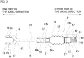
- plastic deformation portions 28a, 28b having an elliptical cross section are respectively provided on the end portion on the other side in the axial direction of the shaft portion 15 of the inner shaft 12, and on the end portion on the one side in the axial direction of the coupling cylinder portion 24a of the outer tube 13. Note that in FIG. 3 , the formation ranges of the plastic deformation portions 28a, 28b are indicated by wavy lines.
- the portion on the other side in the axial portion of the shaft portion 15 of the inner shaft 12 and the coupling cylinder portion 24a of the outer tube 13 are coupled together so as to be able to transmit torque, and so that relative displacement in the axial direction is possible only at the time of a primary collision in which a large impact load is applied in the axial direction.
- the plastic deformation portions 28a, 28b become a resistance when the inner shaft 12 and the outer tube 13 relatively displace in the axial direction, so absorb energy due to a collision when the inner shaft 12 and the outer tube 13 displace relative to each other in the axial direction and the first telescopic shaft 9 contracts.
- Plastic deformation portions 28a, 28b such as described above are formed, for example, as described below.
- a portion on the other side in the axial direction of the shaft portion 15 is inserted a small amount into a portion on the one side in the axial direction of the outer tube 13.
- a portion on the one side in the axial direction of the coupling cylinder portion 24a and a portion on the other side in the axial direction of the shaft portion 15 engage.
- the plastic deformation portions 28a, 28b are formed in the above portion by crushing the portion on the one side in the axial direction of the coupling cylinder portion 24a by a tool from the outside in the radial direction, which causes the inner peripheral surface of the portion on the one side in the axial direction of the coupling cylinder portion 24a and the outer peripheral surface of the portion on the other side in the axial direction of the shaft portion 15 to plastically deform so as to have an elliptical shaped cross section.
- the inner shaft 12 and the outer tube 13 are relatively displaced in the axial direction so as to reduce the overall length of the first telescopic shaft 9, and this overall length of the first telescopic shaft 9 is defined as a specified length in the axial direction during normal operation. In this way, the plastic deformation portion 28a of the inner shaft 12 and the plastic deformation portion 28b of the outer tube 13 are separated from each other in the axial direction.
- the second telescopic shaft 10 includes a male shaft 29 that is a small-diameter shaft, a female shaft 30 that is a large-diameter shaft, a plurality of balls 31, a plurality of rollers 32, a plurality of leaf springs 33, a male joint 46 as a joint shaft, and a dust cover 66.
- the present invention is applied to a coupling portion between the female shaft 30 and the male joint 46 of the second telescopic shaft 10.
- the male shaft 29 is formed in a solid shape over the entire length, and on the outer peripheral surface of a potion on the one side in the axial direction, has first male side axial grooves 34 and second male side axial grooves 35 that each extend in the axial direction and are alternately provided in the circumferential direction.
- the first male side axial grooves 34 have a substantially equilateral trapezoidal cross-sectional shape, and the circumferential width of the opening portion is larger than the circumferential width of the bottom portion.
- the second male side axial grooves 35 have a concave arc-shaped cross section.
- a ring-shaped stopper 36 is fixed to the outer peripheral surface of the end portion on the one side in the axial direction of the male shaft 29.
- a yoke 37 that is separate from the male shaft 29 is fixed to the end portion on the other side in the axial direction of the male shaft 29 by welding.
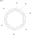
- the female shaft 30 corresponds to a second shaft, and is entirely formed into a hollow tubular shape. As illustrated in FIG. 7 , the female shaft 30, on the inner peripheral surface, has first female side axial grooves 39 and second female side axial grooves 40 that each extend in the axial direction, and are alternately provided in the circumferential direction.
- the first female side axial grooves 39 and the second female side axial grooves 40 have concave arc-shaped cross sections.
- the female shaft 30 is provided, on a portion on the one side in the axial direction, with a cylindrical-shaped fixed cylindrical portion 44 that corresponds to a second coupling portion into which a part of the male joint 46 is inserted.
- a portion adjacent to the one side of the first female side axial grooves 39 and the second female side axial grooves 40 in the axial direction has an inner peripheral side concave-convex portion 41 having a concave-convex shape in the circumferential direction. As illustrated in FIG.
- the inner peripheral side concave-convex portion 41 is configured by forming a plurality of concave grooves 42 that extend in the axial direction and have a concave circular arc cross section on the cylindrical inner peripheral surface of the fixed cylindrical portion 44 so as to be uniformly spaced in the circumferential direction.
- the potions on the other side in the axial direction of the concave grooves 42 are continuous with the portions on the one side in the axial direction of the first female side axial grooves 39 and the second female side axial grooves 40.
- the cross-sectional shape of the concave grooves 42 and the cross-sectional shape of the first female side axial grooves 39 and the second female side axial grooves 40 are the same as each other. Moreover, as illustrated in FIG.
- the phases in the circumferential direction of the first male side axial grooves 34 and the first female side axial grooves 39 are matched, and the phases in the circumferential direction of the second male side axial grooves 35 and the second female side axial grooves 40 are matched.
- a plurality of balls 31 are arranged between the first male side axial grooves 34 and the first female side axial grooves 39.
- leaf springs 33 are arranged between the first male side axial grooves 34 and the plurality of balls 31 to apply a preload to the plurality of balls 31.
- one roller 32 each is arranged between the second male side axial grooves 35 and the second female side axial grooves 40.
- the male shaft 29 and the female shaft 30 are combined to be able to transmit torque and to be able to expand and contract over the entire length in a normal state.
- the plurality of balls 31 and leaf springs 33 transmit torque between the male shaft 29 and the female shaft 30, and as the torque to be transmitted increases, the plurality of rollers 32 transmit the increased portion of the torque.
- the plurality of balls 31 roll between the first male side axial grooves 34 and the first female side axial grooves 39, and the plurality of rollers 32 slide between the second male side axial grooves 35 and the second female side axial grooves 40. Furthermore, in this example, the plurality of balls 31 are pressed against the inner surface of the first female side axial grooves 39 by the elastic force of the leaf springs 33, so looseness between the male shaft 29 and the female shaft 30 is prevented.
- first telescopic shaft 9 and the second telescopic shaft 10 as described above are coaxially coupled together by the joint member 11 so that torque may be transmitted.
- the joint member 11 has a female joint 45 and a male joint 46.
- the female joint 45 is fixed to the coupling cylinder portion 24b of the outer tube 13 of the first telescopic shaft 9, and the male joint 46 is fixed to the female shaft 30 of the second telescopic shaft 10.
- the entire female joint 45 is formed into a substantially cylindrical shape.
- a male serration 47 is provided on the outer peripheral surface of a portion on the one side in the axial direction of the female joint 45
- a female serration 48 is provided on the inner peripheral surface of a portion on the other side in the axial direction of the female joint 45.
- a slit 49 extending in the axial direction is provided in a half portion of the other side in the axial direction of the female joint 45
- a pair of flange portions 50 extending outward in the radial direction is provided on both sides of the slit 49 in the circumferential direction. Screw holes 51 that are coaxial with each other are provided in the pair of flange portions 50.
- the male serration 47 that is provided on the outer peripheral surface on the one side in the axial direction of the female joint 45 is press-fitted (lightly press-fitted) into the second female serration 27 that is provided on the inner peripheral surface of the coupling cylinder portion 24b of the outer tube 13 and engages with a serration engagement.
- a weld bead portion 52 is used to weld and fix the entire circumference between the outer peripheral surface of the female joint 45 and the end surface on the other side in the axial direction of the coupling cylinder portion 24b. In this way, the female joint 45 and the outer tube 13 are coupled together so as to be able to transmit torque.
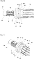
- the male joint 46 corresponds to a first shaft, and as illustrated in FIG. 12 and FIG. 13 , has a joint shaft portion 53 on the one side in the axial direction and a joint cylindrical portion 54 corresponding to a first coupling portion on the other side in the axial direction.
- a male serration 55 is provided over the entire circumference
- a notch 56 is provided in a part of the circumferential direction in a direction perpendicular to the center axis of the joint shaft portion 53.
- the front side in the insertion direction of the joint cylindrical portion 54 corresponds to the other side in the axial direction
- the rear side in the insertion direction of the joint cylindrical portion 54 corresponds to the one side in the axial direction.
- the entire joint cylindrical portion 54 is configured to be substantially cylindrical.
- the joint cylindrical portion 54 has an outer peripheral side concave-convex portion 58 having a concave-convex shape in the circumferential direction on the outer peripheral surface on the other side in the axial direction.
- the outer peripheral side concave-convex portion 58 includes a plurality of ridges 59 each having a semi-cylindrical cross section that extends in the axial direction, formed on the cylindrical surface shaped outer peripheral surface on the other side in the axial direction of the joint cylindrical portion 54 so as to be uniformly spaced in the circumferential direction.
- the joint cylindrical portion 54 has an annular concave groove 57 that is recessed inward in the radial direction and formed around the entire outer peripheral surface of a middle portion in the axial direction that is positioned farther on the one side in the axial direction, which is the rear side in the insertion direction, than the outer peripheral side concave-convex portion 58.
- the joint cylindrical portion 54 has a cylindrical surface shaped first support portion 67 farther on the one side than the axial direction, which is the rear side in the insertion direction, than the annular concave groove 57, and has a cylindrical surface shaped second support portion 68 between the annular concave groove 57 and the outer peripheral side concave-convex portion 58.
- the joint shaft portion 53 of the male joint 46 is inserted inside the portion on the other side in the axial direction of the female joint 45, and the male serration 55 and the female serration 48 are engaged in a serration engagement.
- the female joint 45 and the male joint 46 are coupled so as to be able to transmit torque.
- a bolt (not illustrated) is screwed into the screw holes 51 of the pair of flange portions 50 of the female joint 45.
- the middle portion of the bolt is arranged in the inner side of the notch 56 and prevents the joint shaft portion 53 from coming out of the female joint 45 toward the other side in the axial direction.
- the joint cylindrical portion 54 of the male joint 46 is inserted inside the fixed cylindrical portion 44 of the female shaft 30 until the inclined surfaces 60 that are provided on the outer peripheral surface of the joint cylindrical portion 54 come in contact with the abutment surface 43 that is provided on the inner peripheral surface of the female shaft 30.
- the plurality of ridges 59 of the outer peripheral side concave-convex portion 58 of the male joint 46 are respectively arranged inside the plurality of concave grooves 42 of the inner peripheral side concave-convex portion 41 of the female shaft 30, and the inner peripheral side concave-convex portion 41 and the outer peripheral side concave-convex portion 58 are press-fitted (lightly press-fitted) and the concave-convex portions engage.
- the inner peripheral side concave-convex portion 41 and the outer peripheral side concave-convex portion 58 constitute a torque transmitting portion 69.
- micro-projections are provided on the outer peripheral surface of the ridges 59 of the outer peripheral side concave-convex portion 58 or on the inner peripheral surface of the concave grooves 42 of the inner peripheral side concave-convex portion 41, and by plastically deforming these micro-protrusions when concave-convex portions of the inner peripheral side concave-convex portion 41 and the outer peripheral side concave-convex portion 58 engage, it is possible to eliminate a gap between the outer surface of the outer peripheral side concave-convex portion 58 and the inner surface of the inner peripheral side concave-convex portion 41.
- a plurality of convex embossed portions 62 is provided on the inner peripheral surface of the fixed cylindrical portion 44 of the female shaft 30, and concave portions 63 are provided at a plurality of locations on the outer peripheral surface that coincide with the embossed portions 62.
- the embossed portions 62 are formed in portions of a large diameter portion 64, which is the inner peripheral surface of the portion on the one side of the fixed cylindrical portion 44 in the axial direction, that coincide in the axial direction with the annular concave groove 57 of the male joint 46, and are arranged inside the annular concave groove 57.
- the embossed portions 62 and the annular concave groove 57 constitute a retaining portion 70.
- the embossed portions 62 have a substantially columnar shape, and are provided so as to be uniformly spaced in the circumferential direction of the fixed cylindrical portion 44.
- the embossed portions 62 are provided at four positions that are shifted by a phase in the circumferential direction of 90 degrees each; however, the embossed portions 62 may be shifted by a phase in the circumferential direction of 180 degrees and provided at only two locations on opposite sides of the fixed cylindrical portion 44 in the radial direction. In this case as well, it is possible to sufficiently prevent the male joint 46 from coming out in the axial direction from the female shaft 30. As illustrated in FIG.
- the embossed portions 62 are formed on the inner peripheral surface of the fixed cylindrical portion 44 as described in the following.
- the tip end portion of a tool (pin) having a columnar shape presses a plurality of locations in the circumferential direction on the outer peripheral surface of the fixed cylindrical portion 44 inward in the radial direction to semi-shear (cut out half of) this portion.
- substantially cylindrical concave portions 63 are fonned on the outer peripheral surface of the fixed cylindrical portion 44, and the convex embossed portions 62 are formed by causing a plurality of locations in the circumferential direction of the inner peripheral surface of the fixed cylindrical portion 44 to project inward in the radial direction.
- concave portions 63 are formed on the outer peripheral surface of the fixed cylindrical portion 44, and the embossed portions 62 are formed by causing the material that is pushed out by forming the concave portions 63 to project inward in the radial direction from the inner peripheral surface of the fixed cylindrical portion 44.
- a pair of tools is arranged on opposite sides of the fixed cylindrical portion 44 in the radial direction, and two embossed portions 62 (concave portions 63) may be formed at the same time by moving the tip end portions of the pair of tools toward each other.
- the concave portions 63 have a depth dimension that is smaller than the plate thickness of the fixed cylindrical portion 44 and have an inner surface shape that matches the outer surface shape of the tip end portion of the tool.
- the embossed portions 62 have substantially the same height as the depth of the concave portions 63.
- the convex embossed portions 62 are formed on the inner peripheral surface of the fixed cylindrical portion 44 by embossing using a small-diameter tool (pin), so together with being able to prevent the roundness of the outer peripheral surface of the fixed cylindrical portion 44 from being reduced, it is possible to keep the press load required for forming the embossed portions 62 low.
- a weld bead portion 61 described below has not yet been formed between the female shaft 30 and the male joint 46; however, the inner peripheral side concave-convex portion 41 and the outer peripheral side concave-convex portion 58 are press fitted together, so together with being able to maintain concentricity between the female shaft 30 and the male joint 46, it is possible to prevent looseness between the female shaft 30 and the male joint 46.
- the force that is applied to the fixed cylindrical portion 44 from the tool may be supported by the first support portion 67 and the second support portion 68, so from this aspect as well, it is possible to prevent a reduction in the roundness of the outer peripheral surface of the fixed cylindrical portion 44.
- the weld bead portion 61 has a cross-sectional shape such as, for example, a substantially quarter circle shape, a substantially triangular shape, a substantially square shape, or the like, and has an outer diameter that is the same as the outer diameter of the fixed cylindrical portion 44 or smaller than the outer diameter of the fixed cylindrical portion 44.
- This kind of weld bead portion 61, retaining portion 70, and torque transmitting portion 69 are arranged side-by-side in this order in the axial direction from the one side to the other side in the axial direction (from the rear side to the front side in the insertion direction of the joint cylindrical portion 54).
- the joint cylindrical portion 54 is inserted inside the fixed cylindrical portion 44, and the embossed portions 62 are formed at a plurality of locations in the circumferential direction on the inner peripheral surface of the fixed cylinder portion 44, after which the weld bead portion 61 is formed in a portion separated in the axial direction from the embossed portions 62 between the outer peripheral surface of the joint cylindrical portion 54 and the end surface of the female shaft 30.
- the weld bead portion 61 and the embossed portions 62 arranged on the inner side of the annular concave groove 57 are separated from each by an amount equal to the dimension in the axial direction of the first support portion 67 that is provided on the outer peripheral surface of the joint cylindrical portion 54, so it is possible to effectively prevent welding heat from being transmitted to the embossed portions 62.
- the weld bead portion 61 is also separated in the axial direction from the torque transmitting portion 69, so it is also possible to prevent the welding heat that occurs when forming the weld bead portion 61 from being transmitted to the torque transmitting portion 69.
- the inner peripheral side concave-convex portion 41 and the outer peripheral side concave-convex portion 58 are press fitted together, so when forming the weld bead portion 61, together with being able to maintain concentricity between the female shaft 30 and the male joint 46, it is also possible to prevent looseness between the female shaft 30 and the male joint 46.
- the intermediate shaft 5a as described above is arranged so as to pass through a through hole (not illustrated) that is provided in a dash panel of the vehicle body.
- a specified gap needs to be provided between the second telescopic shaft 10 and the through hole in the dash panel in order to allow the second telescopic shaft 10 to expand or contract in accordance with vibrations and the like while traveling.
- the dust cover 66 is externally fitted to the female shaft 30 of the second telescopic shaft 10.
- the gap between the inner peripheral surface of a cylindrical member 74 that is fixed to the through hole in the dash panel and the outer peripheral surface of the female shaft 30 is covered.
- the dust cover 66 includes a bush portion 75, a bellows portion 76, and a pair of seal portions 77a, 77b.
- the bush portion 75 is a portion that functions as a sliding bearing, and, for example, is made of a synthetic resin, and is externally fitted to the female shaft 30 so as to be capable of relative rotation and relative movement in the axial direction with respect to the female shaft 30.
- the bellows portion 76 for example, is made of synthetic rubber, has a substantially U-shaped cross-sectional shape, and is flexible. The inner peripheral edge of this kind of bellows portion 76 is fixed to the outer peripheral surface of the bush portion 75 and the outer peripheral edge is fixed to the cylindrical member 74.
- the seal portion 77a is fixed to the end portion on the other side in the axial direction of the bush portion 75 to prevent foreign matter from entering inside of the bush portion 75 from the vehicle interior, and to prevent grease from leaking from the inner side of the bush portion 75 into the vehicle interior.
- the seal portion 77b is fixed to the end portion on the one side of the bush portion 75 in the axial direction and together with preventing foreign matter from entering inside the bush portion 75 from the engine room, prevent grease from leaking into the engine room from the inside of the bush portion 75.
- the seal portions 77a, 77b suppress mechanical noise that is generated in the engine room from leaking into the vehicle interior.
- the dust cover 66 such as described above is fitted to the female shaft 30 with the male joint 46 in a state of being fixed to the end portion on the one side in the axial direction of the female shaft 30.
- the outer diameter from the end portion on the one side in the axial direction of the female shaft 30 to the portion where the dust cover 66 is fitted is smaller than the inner diameter of the bush portion 75, and is constant in the axial direction.
- the outer diameter of the weld bead portion 61 is smaller than the inner diameter of the bush portion 75.
- the outer diameter from the end portion on the one side in the axial direction of the female shaft 30 to the portion where the dust cover 66 is fitted is slightly larger than the inner diameter of the seal portions 77a, 77b. Therefore, there is interference between the seal portions 77a, 77b and the outer peripheral surface of the female shaft 30.
- the intermediate shaft 5a of the present example as described above expands and contracts by the relative displacement in the axial direction of the male shaft 29 and the female shaft 30 of the second telescopic shaft 10. This prevents vibration that is inputted from the tire during traveling from being transmitted to the steering wheel 1.
- the first telescopic shaft 9 and the second telescopic shaft 10 both contract.
- the intermediate shaft 5a contracts over the entire length while absorbing the impact load. This prevents the steering wheel 1 from being pushed up to the driver side.
- the torque transmitting portion 69 that is formed by the engagement of the concave and convex portions of the outer peripheral side concave-convex portion 58 of the male joint 46 and the inner peripheral side concave-convex portion 41 of the female shaft 30 is able to transmit torque between the male joint 46 and the female shaft 30.
- the retaining portion 70 formed by arranging the embossed portions 62 formed on the inner peripheral surface of the female shaft 30 on the inner side of the annular concave groove 57 that is formed in the male joint 46, is able to prevent the male joint 46 from coming out in the axial direction from the female shaft 30.
- the retaining portion 70 and the torque transmitting portion 69 are arranged so as to be separated in the axial direction from the weld bead portion 61. Therefore, it is possible to effectively prevent the welding heat that occurs when forming the welding bead portion 61 from being transmitted to the retaining portion 70 and the torque transmitting portion 69. Accordingly, it is possible to effectively prevent the torque transmission function from being impaired or the retaining function from being impaired due to the formation of the weld bead portion 61.
- the convex embossed portions 62 of the retaining portion 70 are formed on the inner peripheral surface of the fixed cylindrical portion 44 by embossing using a small-diameter tool, it is possible to prevent a reduction in the roundness of the outer peripheral surface of the fixed cylindrical portion 44.
- the first support portion 67 and the second support portion 68 are provided on both sides of the annular groove 57 of the outer peripheral surface of the joint cylindrical portion 54, and a gap in the radial direction and gaps in the axial direction are provided between the embossed portions 62 and the annular concave groove 57, it is possible to prevent a reduction in the roundness of the outer peripheral surface of the fixed cylindrical portion 44. Therefore, it is possible to effectively prevent the dust cover 66 (the bush portion 75) from not being able to be externally fitted on the female shaft 30, and prevent a reduction of the workability of the work of externally fitting the dust cover 66.
- the concave portions 63 that are formed on the outer peripheral surface of the female shaft 30 and the weld bead portion 61 are arranged so as to be spaced apart in the axial direction, so it is possible to prevent the concave portions 63 from being covered by the weld bead portion 61. For this reason, the work of checking whether or not the embossed portions 62 are formed can be easily performed.
- the shaft portion 15 of the inner shaft 12 that constitutes the first telescopic shaft 9 may be provided with a male serration 22 over the entire length. In a case where such a configuration is adopted, torque may be transmitted between the inner shaft 12 and the outer tube 13 even in a state in which the entire length of the first telescopic shaft 9 is contracted.
- a second example of an embodiment of the present invention will be described with reference to FIG. 14 to FIG. 16 .
- a feature of this example is that the coupling structure between the female joint 45a and the outer tube 13a, which is a pair of joints constituting the first telescopic shaft 9 of the intermediate shaft 5a, is devised.
- the female joint 45a is a first shaft and a joint shaft
- the outer tube 13a is a second shaft and a large-diameter shaft.
- the female joint 45a has a cylindrical portion 65 on one side in the axial direction that corresponds to a first coupling portion.
- a male serration 47a having concave-convex shape in the circumferential direction corresponding to an outer peripheral side concave-convex portion, an annular concave groove 57a, and an auxiliary male serration 78 having a concave-convex shape in the circumferential direction corresponding to an auxiliary outer peripheral side concave-convex portion are arranged in the axial direction in this order.
- the male serration 47a is provided at an end portion on the one side in the axial direction, which is the front side in the insertion direction of the female joint 45a, of the outer peripheral surface of the cylindrical portion 65.
- the annular concave groove 57a is provided at an intermediate portion in the axial direction of the cylindrical portion 65 that is located on the other side in the axial direction of the male serration 47a.
- the auxiliary male serration 78 is provided farther on the other side in the axial direction, which is the rear side in the insertion direction of the female joint 45a, than the annular concave groove 57a.
- an annular concave groove 57a which is concave inward in the radial direction, is provided between the male serration 47a and the auxiliary male serration 78.
- a second female serration 27 having a concave-convex shape in the circumferential direction and corresponding to the inner peripheral side concave-convex portion is provided on the inner peripheral surface of the coupling cylinder portion 24b provided on the other side in the axial direction of the outer tube 13a that corresponds to the second coupling portion.
- the auxiliary male serration 78 may be omitted, and a cylindrical surface shaped first support portion may be provided.
- the cylindrical portion 65 of the female joint 45a is inserted inside the coupling cylinder portion 24b of the outer tube 13a, and the male serration 47a and the second female serration 27 are press-fitted together and engage in a serration engagement.
- the male serration 47a and the second female serration 27 constitute a torque transmitting portion 69a.
- a plurality of convex embossed portions 62a formed in a portion of the inner peripheral surface of the coupling cylinder portion 24b that is aligned in the axial direction with the annular groove 57a of the female joint 45a are arranged in the inner side of the annular concave groove 57a to form a retaining portion 70a.
- the embossed portions 62a are provided at uniform intervals in the circumferential direction of the coupling cylinder portion 24b.
- a plurality of locations in the circumferential direction on the outer peripheral surface of the coupling cylinder portion 24b are pressed inward in the radial direction by the tip end portion of a tool to semi-shear this portion.
- substantially cylindrical concave portions 63a are formed on the outer peripheral surface of the coupling cylinder portion 24b, and a plurality of locations in the circumferential direction of the inner peripheral surface of the coupling cylinder portion 24b are made to project inward in the radial direction to form the convex embossed portions 62a.
- the portion between the outer peripheral surface of the female joint 45a and the end surface on the other side in the axial direction of the coupling cylinder portion 24b is welded and fixed over the entire circumference by a weld bead portion 52a. Therefore, the weld bead portion 52a, the retaining portion 70a, and the torque transmitting portion 69a are arranged side-by-side in this order from the other side to the one side in the axial direction (from the rear side to the front side in the insertion direction of the cylindrical portion 65).
- a portion on the one side of the female joint 45a in the axial direction is inserted inside the coupling cylinder portion 24b, and after the embossed portions 62a are formed at a plurality of locations in the circumferential direction on the inner peripheral surface of the coupling cylinder portion 24b, the weld bead portion 52a is formed between the outer peripheral surface of the female joint 45a and the end surface on the other side in the axial direction of the coupling cylindrical portion 24b that are separated from the embossed portions 62a in the axial direction. This prevents the effect of welding heat that occurs when forming the weld bead portion 52a from being transmitted to the embossed portions 62a.
- a third example of an embodiment will be described with reference to FIG. 17 .
- This example is a modification of the second example, and a feature of this example is that the coupling structure of a solid shaft 80, which is a small-diameter shaft internally fitted with a large-diameter shaft (not illustrated) so as to be able to transmit torque and so that relative displacement in the axial direction is possible, and a female joint 45b is devised.
- the solid shaft 80 is a first shaft
- the female joint 45b is a second shaft.
- the solid shaft 80 has an insertion shaft portion 81 on the other side in the axial direction that corresponds to a first coupling portion.
- a male serration 82 having a concave-convex shape in the circumferential direction corresponding to an outer peripheral side concave-convex portion, an annular concave groove 57b, and a first support portion 67a are provided on the outer peripheral surface of the insertion shaft portion 81.
- the male serration 82 is provided at the end portion of the outer peripheral surface of the insertion shaft 81 on the other side in the axial direction, which is the front side in the insertion direction of the insertion shaft portion 81.
- the annular concave groove 57b is provided at an intermediate portion of the insertion shaft portion 81 that is positioned farther on the one side in the axial direction than the male serration 82.
- the first support portion 67a is provided farther on the one side in the axial direction, which is the rear side in the insertion direction of the insertion shaft portion 81, than the annular concave groove 57b. Therefore, in this example, the annular concave groove 57b that is concave inward in the radial direction is provided between the male serration 82 and the first support portion 67a.
- a female serration 83 having a concave-convex shape in the circumferential direction and corresponding to an inner peripheral side concave-convex portion is provided on the inner peripheral surface of a cylindrical portion 65a corresponding to a second coupling portion at a portion on the one side in the axial direction of the female joint 45b.
- the male serration 82 and the female serration 83 are press-fitted together and engage in a serration engagement.
- the male serration 82 and the female serration 83 constitute a torque transmitting portion 69b.
- a plurality of convex embossed portions 62b that are formed on a portion of the inner peripheral surface of cylindrical portion 65a that coincides in the axial direction with the annular concave groove 57b of the solid shaft 80 are arranged on the inner side of the annular concave groove 57b to form a retaining portion 70b.
- Concave portions 63b are provided portions of the outer peripheral surface of the cylindrical portion 65a that coincide with the embossed portions 62b.
- the portion between the outer peripheral surface of the solid shaft 80 and the end surface on the one side of the cylindrical portion 65a in the axial direction is welded and fixed over the entire circumference by a weld bead portion 52b. Therefore, the weld bead portion 52b, the retaining portion 70b, and the torque transmitting portion 69b are arranged side-by-side in this order from the one side to the other side in the axial direction (from the front side to the rear side in the insertion direction of the cylindrical portion 65a).
- the torque transmitting portion 69b is able to maintain the torque transmitting function, and the retaining portion 70b is able to prevent separation between the solid shaft 80 and the female joint 45b.
- Other configurations and operational effects are the same as those of the first and second examples.
- the number and shape of the embossed portions that are formed on the inner peripheral surface of the second coupling portion are not limited to the structures described in each example of an embodiment of the present invention, and the structure may be modified as long as the function for preventing the first shaft from coming out of the second shaft may be achieved.
Landscapes
- Engineering & Computer Science (AREA)
- General Engineering & Computer Science (AREA)
- Mechanical Engineering (AREA)
- Chemical & Material Sciences (AREA)
- Combustion & Propulsion (AREA)
- Transportation (AREA)
- Ocean & Marine Engineering (AREA)
- Steering Controls (AREA)
- Shafts, Cranks, Connecting Bars, And Related Bearings (AREA)
Description
- The present invention relates to a shaft coupling structure that constitutes a torque transmitting shaft that is assembled in a steering apparatus or the like of an automobile, and relates to a telescopic shaft that includes the torque transmitting shaft and is configured so that the entire length thereof is able to expand or contract in a normal state and/or in a case where an impact load of a specified magnitude or greater is applied in the axial direction.
-
FIG. 18 illustrates a steering apparatus for an automobile described inJP 2017-025964A steering wheel 1, asteering shaft 2, asteering column 3, a pair ofuniversal joints intermediate shaft 5, asteering gear unit 6, and a pair oftie rods 7. - The
steering wheel 1 is attached to a rear end portion of asteering shaft 2 that is rotatably supported inside thesteering column 3. A front end portion of thesteering shaft 2 is connected to aninput shaft 8 of thesteering gear unit 6 via the pair ofuniversal joints intermediate shaft 5. Then, by converting rotation of theinput shaft 8 into a linear motion of a rack (not illustrated), the pair oftie rods 7 are pushed and pulled, and a steering angle corresponding to the operation amount of thesteering wheel 1 is applied to steered wheels. Note that the front-rear direction refers to the front-rear direction of a vehicle body in which the steering apparatus is assembled. - In the field of steering apparatuses for an automobile, a torque transmitting shaft used for transmitting torque, such as an intermediate shaft or the like, may be formed by coupling a plurality of shafts. In this case, a pair of shafts arranged adjacent to each other is coupled by welding so that torque transmission may be performed between the pair of shafts.
- In a steering apparatus for a vehicle as described in
JP 2017-025959A -
EP 2 039 587 A1 -
JP 2002 293 252 A -
EP 2 735 752 A2 - Patent Literature 1:
JP 2017-025964A - In recent years, the demand for reliability of a torque transmitting shaft has been increasing. In the case of a torque transmitting shaft configured by connecting a plurality of shafts, the torque transmitting function may be ensured even in a case where a defect such as cracking or peeling occurs in a welded portion coupling the pair of shafts, and it is also required that the pair of shafts do not become separated.
- In view of the circumstances described above, an object of the present invention is to provide a shaft coupling structure of a torque transmission shaft capable of ensuring a torque transmitting function even in a case where defects occur in a welded portion, and preventing a plurality of shafts of the torque transmission shaft from separating, and a telescopic shaft including the torque transmission shaft and capable of contracting over the entire length.
- The shaft coupling structure of the present invention includes a first shaft, a second shaft, and a weld bead portion.
- The first shaft has a first coupling portion. The first coupling portion may have a hollow cylindrical shape, or may have a solid shape.
- The second shaft has a second coupling portion having a cylindrical shape into which the first coupling portion is inserted.
- The weld bead portion welds and fixes together an end portion in the axial direction of the second coupling portion and a portion of an outer peripheral surface of the first shaft that is exposed from the second coupling portion.
- The first coupling portion, on an outer peripheral surface thereof, has an outer peripheral side concave-convex portion having a concave-convex shape in the circumferential direction and is arranged on an end portion on the front side in the insertion direction of the first coupling portion, and an annular concave groove that is arranged farther on the rear side in the insertion direction of the first coupling portion than the outer peripheral side concave-convex portion.
- The second coupling portion, on an inner peripheral surface thereof, has an inner peripheral side concave-convex portion having an concave-convex shape in the circumferential direction and constitutes a torque transmitting portion by engaging with the outer peripheral side concave-convex portion with a concave-convex engagement, and a convex embossed portion constitutes a retaining portion with arranged on the inner side of the annular concave groove, and has a concave portion in a portion on an outer peripheral surface thereof that coincide with the embossed portion.
- The weld bead portion, the retaining portion, and the torque transmitting portion are arranged side-by-side in this order in the axial direction of the first shaft.
- The outer peripheral side concave-convex portion may be press-fitted (lightly pressed) with the inner peripheral side concave-convex portion.
- In the present invention, the embossed portion may be arranged at a plurality of locations in the circumferential direction of the second coupling portion.
- In this case, the embossed portions may be arranged at two or four locations at uniform intervals in the circumferential direction of the second coupling portion.
- Alternatively, the embossed portion may be arranged at one location in the circumferential direction of the second coupling portion.
- A gap in the radial direction of the first shaft may be provided between a bottom surface of the annular concave groove and a tip end surface of the embossed portion. According to the invention, gaps in the axial direction of the first shaft are provided between inner side surfaces of the annular concave groove that face each other and an embossed portion.
- The first coupling portion may have a first support portion having a cylindrical surface shape that is farther on the rear side in the insertion direction of the first coupling portion than the annular concave groove.
- In this case, the first coupling portion may have a second support portion having a cylindrical surface shape between the annular concave groove and the outer peripheral side concave-convex portion.
- Alternatively, the first coupling portion, on a portion farther on the rear side in the insertion direction of the first coupling portion than the annular concave groove, may have an auxiliary outer peripheral side concave-convex portion having a concave-convex shape in the circumferential direction that engages with the inner peripheral side concave-convex portion with a concave-convex engagement.
- In a first aspect of the telescopic shaft according to the present invention, the telescopic shaft includes a large-diameter shaft; a small-diameter shaft that is fitted inside the large-diameter shaft so as to be able to transmit torque to the large-diameter shaft and displace in the axial direction relative to the large-diameter shaft; and a joint shaft that is coupled to an end portion of the large-diameter shaft in the axial direction.
- The large-diameter shaft and the joint shaft are coupled together by the shaft coupling structure according to the present invention, the large diameter shaft is the second shaft, and the joint shaft is the first shaft.
- In the first aspect of the telescopic shaft according to the present invention, the telescopic shaft may include a dust cover that is externally fitted to the large-diameter shaft.
- Of the large-diameter shaft, the outer diameter from an end portion in the axial direction on the side where the joint shaft is coupled to the portion where the dust cover is externally fitted may be constant in the axial direction.
- In a second aspect of the telescopic shaft according to the present invention, the telescopic shaft includes a large-diameter shaft; a small-diameter shaft that is fitted inside the large-diameter shaft so as to be able to transmit torque to the large-diameter shaft and displace in the axial direction relative to the large-diameter shaft; and a joint shaft that is coupled to an end portion of the small-diameter shaft in the axial direction.
- The small-diameter shaft and the joint shaft are coupled together by the shaft coupling structure according to the present invention, the small-diameter shaft is the first shaft, and the joint shaft is the second shaft.
- In both the first and second aspects of the telescopic shaft according to the present invention, the telescopic shaft may constitute an intermediate shaft of a steering apparatus for an automobile.
- In this case, the telescopic shaft may be configured to be able to expand and contract over the entire length in a normal state where no collision accident occurs in the automobile, and may be configured to be able to contract over the entire length only when a collision accident occurs in the automobile and a load of a specified magnitude or greater is applied in the axial direction to the telescopic shaft.
- With the shaft coupling structure and the telescopic shaft according to the present invention, even in a case where defects occur in a weld portion, it is possible to maintain a torque transmitting function and it is possible to prevent separation of a plurality of shafts of a torque transmitting shaft.
-
-
FIG. 1 is a schematic diagram illustrating an example of a steering apparatus to which a shaft coupling structure according to a first example of an embodiment of the present invention is applied. -
FIG. 2 is a cross-sectional view illustrating an intermediate shaft that is taken out of the steering apparatus of the first example illustrated inFIG. 1 . -
FIG. 3 is a cross-sectional view illustrating a first telescopic shaft that is take out of the intermediate shaft of the first example illustrated inFIG. 2 by separating the first telescopic shaft from the intermediate shaft at a position of a joint member. -
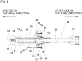
FIG. 4 is a cross-sectional view illustrating a second telescopic shaft that is take out of the intermediate shaft of the first example illustrated inFIG. 2 by separating the second telescopic shaft from the intermediate shaft at a position of a joint member. -
FIG. 5 is an enlarged view of a portion A inFIG. 4 . -
FIG. 6 is a partially enlarged view ofFIG. 5 . -
FIG. 7 is a cross-sectional view of section D-D inFIG. 5 . -
FIG. 8 is a cross-sectional view of section E-E inFIG. 5 . -
FIG. 9 is an end portion cross-sectional view of a female shaft corresponding to the second shaft of the first example. -
FIG. 10 is a partial perspective view of a portion corresponding to a portion B inFIG. 4 . -
FIG. 11 is a partial perspective view of a portion corresponding to a portion B inFIG. 4 . -
FIG. 12 is a side view of a male joint corresponding to the first shaft of the first example. -
FIG. 13 is a perspective view of the male joint corresponding to the first shaft of the first example. -
FIG. 14 is an enlarged view of a portion of a first telescopic shaft of a second example of an embodiment of the present invention, the portion corresponding to portion C inFIG. 3 . -
FIG. 15 is a perspective view of an outer tube corresponding to a second shaft of the second example. -
FIG. 16 is a side view of a female joint corresponding to a first shaft of the second example. -
FIG. 17 is an enlarged view of a portion of a first telescopic shaft of a third example of an embodiment of the present invention, corresponds toFIG. 14 . -
FIG. 18 is a partial cross-sectional side view illustrating a conventionally known steering apparatus. - A first example of an embodiment of the present invention will be described with reference to
FIG. 1 to FIG. 13 . In the present example, the structure of anintermediate shaft 5a is devised among a plurality of torque transmitting shafts of a steering apparatus. More specifically, of a firsttelescopic shaft 9 and a secondtelescopic shaft 10 of theintermediate shaft 5a, the joint structure of a male joint 46 and afemale shaft 30 of the secondtelescopic shaft 10 arranged on the rear side of the vehicle is devised. Hereinafter, the overall structure of the steering apparatus and theintermediate shaft 5a will be described, and the features of the present example will be described. - A steering apparatus for an automobile includes a
steering wheel 1, asteering shaft 2, asteering column 3, a pair ofuniversal joints intermediate shaft 5a, asteering gear unit 6, and a pair oftie rods 7. - The steering
shaft 2 is rotatably supported inside thesteering column 3 that is supported by the vehicle body. Asteering wheel 1 that is operated by a driver is attached to the rear end portion of thesteering shaft 2, and the front end portion of thesteering shaft 2 is connected to aninput shaft 8 of thesteering gear unit 6 via the pair ofuniversal joints intermediate shaft 5a. Accordingly, when the driver rotates thesteering wheel 1, the rotation of thesteering wheel 1 is transmitted to theinput shaft 8 of thesteering gear unit 6. The rotation of theinput shaft 8 is converted into linear motion of a rack that engages with theinput shaft 8, and pushes and pulls the pair oftie rods 7. As a result, a steering angle corresponding to the operation amount of thesteering wheel 1 is applied to the steered wheels. - The
intermediate shaft 5a is a torque transmitting shaft that transmits torque, and as illustrated inFIG. 2 , is configured by the firsttelescopic shaft 9 and the secondtelescopic shaft 10, each of which is capable of expanding or contracting in the axial direction, being coupled in series by ajoint member 11 so as to be able to transmit torque. The firsttelescopic shaft 9 is arranged on the front side and the secondtelescopic shaft 10 is arranged on the rear side in the front-rear direction of the vehicle body in which the steering apparatus is assembled. In the description of the present invention, for convenience, the side on which the firsttelescopic shaft 9 is arranged is referred to as one side in the axial direction of theintermediate shaft 5a, and the side on which the secondtelescopic shaft 10 is arranged is referred to as the other side in the axial direction of theintermediate shaft 5a. - The first
telescopic shaft 9 is configured to be able to contract over the entire length only in a case where an impact load having a magnitude greater than or equal to a specified value is applied in the axial direction, whereas the secondtelescopic shaft 10 is configured to be able to expand and contract over the entire length in a normal state in which no collision accident has occurred. For this reason, in a normal state, the overall length of theintermediate shaft 5a changes only by the expansion or contraction of the secondtelescopic shaft 10; however, when a collision accident occurs, the overall length is reduced by contraction of both the firsttelescopic shaft 9 and the secondtelescopic shaft 10. Note that theintermediate shaft 5a of this embodiment is used in a large vehicle, and has an axial dimension longer than an intermediate shaft used in a general ordinary passenger car. - As illustrated in
FIG. 3 , the firsttelescopic shaft 9 includes aninner shaft 12, anouter tube 13, and a female joint 45. Theinner shaft 12 and theouter tube 13 are coupled together so that torque may be transmitted, and so that relative displacement in the axial direction is possible only at the time of a primary collision. In other words, theinner shaft 12 and theouter tube 13 are coupled together so that relative displacement in the axial direction is not possible in the normal state. - The
inner shaft 12 is made of metal and has ayoke portion 14 on one side in the axial direction and ashaft portion 15 on the other side in the axial direction. In this example, theyoke portion 14 and theshaft portion 15 are integrally provided. In other words, theyoke portion 14 and theshaft portion 15 are integrally formed by plastically deforming the raw material by forging or the like, instead of being connected by fitting, welding, or the like. - The
yoke portion 14, together with anotheryoke 16 that is connected to theinput shaft 8 of thesteering gear unit 6 and a cross shaft (not illustrated), form the universal joint 4d, and has abase portion 17 and a pair ofarm portions 18. Thebase portion 17 has a central portion in the radial direction on the other side in the axial direction thereof, that is continuous with a portion on the one side in the axial direction of theshaft portion 15. A portion on the outer side in the radial direction of the side surface on the other side in the axial direction of thebase portion 17 is anannular surface 19 that exists on a virtual plane orthogonal to the center axis of theshaft portion 15. - The pair of
arm portions 18 are formed in a substantially flat plate shape, and extend to the one side in the axial direction from two positions on diametrically opposite sides of thebase portion 17. Moreover,circular holes 20 for rotatably supporting the shaft portion of the cross shaft are provided coaxially with each other in the tip end portions of thearm portions 18. - The
shaft portion 15 has a substantially columnar shape and is formed in a solid shape over substantially the entire length. Ahollow portion 21 that is opened only on the end surface on the other side in the axial direction of theshaft portion 15 is provided on the other side in the axial direction of theshaft portion 15. Amale serration 22 is provided on the outer peripheral surface of the half portion on the other side in the axial direction of theshaft portion 15. On the other hand, a concavecurved surface 23 having a concave arc-shaped cross section is provided on the outer peripheral surface of the end portion on the one side in the axial direction of theshaft portion 15. The concavecurved surface 23 is a so-called corner R portion, has a single radius of curvature r, and is smoothly continuous on theannular surface 19 that is the side surface on the other side in the axial direction of thebase portion 17 of theyoke portion 14. - The
outer tube 13 is made of metal and has a hollow circular tubular shape. A pair ofcoupling cylinder portions outer tube 13, and a bellows-like bellows portion 25 is provided at a middle portion in the axial direction of theouter tube 13. - A first
female serration 26 is provided on the inner peripheral surface of thecoupling cylinder portion 24a on the one side in the axial direction of the pair ofcoupling cylinder portions female serration 27 is provided on the inner peripheral surface of thecoupling cylinder portion 24b on the other side in the axial direction. - The
bellows portion 25 is a portion that absorbs an impact load accompanying a collision by being plastically deformed so as to be bent at the time of an offset collision, and has a torsion strength such that thebellows portion 25 is not deformed by a load in the torsional direction applied due to the operator operating thesteering wheel 1. Thebellows portion 25 is configured by alternately arranging a plurality of peak portions, which are large-diameter portions, and valley portions, which are small-diameter portions, in the axial direction. In addition, in this example, the tops of the peak portions and the bottoms of the valley portions have an arc shaped cross section. - In order to couple the
inner shaft 12 and theouter tube 13 so that torque may be transmitted and so that relative displacement in the axial direction at the time of a primary collision is possible, amale serration 22 of theinner shaft 12 and the firstfemale serration 26 of theouter tube 13 engage with a serration engagement, and the fitting portion between theinner shaft 12 and theouter tube 13 is a so-called elliptical fitting. In other words,plastic deformation portions shaft portion 15 of theinner shaft 12, and on the end portion on the one side in the axial direction of thecoupling cylinder portion 24a of theouter tube 13. Note that inFIG. 3 , the formation ranges of theplastic deformation portions - With the configuration described above, the portion on the other side in the axial portion of the
shaft portion 15 of theinner shaft 12 and thecoupling cylinder portion 24a of theouter tube 13 are coupled together so as to be able to transmit torque, and so that relative displacement in the axial direction is possible only at the time of a primary collision in which a large impact load is applied in the axial direction. In addition, theplastic deformation portions inner shaft 12 and theouter tube 13 relatively displace in the axial direction, so absorb energy due to a collision when theinner shaft 12 and theouter tube 13 displace relative to each other in the axial direction and the firsttelescopic shaft 9 contracts. -
Plastic deformation portions - First, a portion on the other side in the axial direction of the
shaft portion 15 is inserted a small amount into a portion on the one side in the axial direction of theouter tube 13. In other words, a portion on the one side in the axial direction of thecoupling cylinder portion 24a and a portion on the other side in the axial direction of theshaft portion 15 engage. Next, theplastic deformation portions coupling cylinder portion 24a by a tool from the outside in the radial direction, which causes the inner peripheral surface of the portion on the one side in the axial direction of thecoupling cylinder portion 24a and the outer peripheral surface of the portion on the other side in the axial direction of theshaft portion 15 to plastically deform so as to have an elliptical shaped cross section. Then, theinner shaft 12 and theouter tube 13 are relatively displaced in the axial direction so as to reduce the overall length of the firsttelescopic shaft 9, and this overall length of the firsttelescopic shaft 9 is defined as a specified length in the axial direction during normal operation. In this way, theplastic deformation portion 28a of theinner shaft 12 and theplastic deformation portion 28b of theouter tube 13 are separated from each other in the axial direction. - As illustrated in
FIG. 4 , the secondtelescopic shaft 10 includes amale shaft 29 that is a small-diameter shaft, afemale shaft 30 that is a large-diameter shaft, a plurality ofballs 31, a plurality ofrollers 32, a plurality ofleaf springs 33, a male joint 46 as a joint shaft, and adust cover 66. In the present example, the present invention is applied to a coupling portion between thefemale shaft 30 and the male joint 46 of the secondtelescopic shaft 10. - The
male shaft 29 is formed in a solid shape over the entire length, and on the outer peripheral surface of a potion on the one side in the axial direction, has first male sideaxial grooves 34 and second male sideaxial grooves 35 that each extend in the axial direction and are alternately provided in the circumferential direction. The first male sideaxial grooves 34 have a substantially equilateral trapezoidal cross-sectional shape, and the circumferential width of the opening portion is larger than the circumferential width of the bottom portion. On the other hand, the second male sideaxial grooves 35 have a concave arc-shaped cross section. A ring-shapedstopper 36 is fixed to the outer peripheral surface of the end portion on the one side in the axial direction of themale shaft 29. As a result, theballs 31 that are arranged inside the first male sideaxial grooves 34 and therollers 32 that are arranged inside the second male sideaxial grooves 35 are prevented from coming out to the one side in the axial direction from the first male sideaxial grooves 34 and the second male sideaxial grooves 35. In addition, ayoke 37 that is separate from themale shaft 29 is fixed to the end portion on the other side in the axial direction of themale shaft 29 by welding. Theyoke 37, together with anotheryoke 38 that is connected to the front end portion of thesteering shaft 2 and a cross shaft, constitute theuniversal joint 4c. - The
female shaft 30 corresponds to a second shaft, and is entirely formed into a hollow tubular shape. As illustrated inFIG. 7 , thefemale shaft 30, on the inner peripheral surface, has first female sideaxial grooves 39 and second female sideaxial grooves 40 that each extend in the axial direction, and are alternately provided in the circumferential direction. The first female sideaxial grooves 39 and the second female sideaxial grooves 40 have concave arc-shaped cross sections. - The
female shaft 30 is provided, on a portion on the one side in the axial direction, with a cylindrical-shaped fixedcylindrical portion 44 that corresponds to a second coupling portion into which a part of the male joint 46 is inserted. Of the inner peripheral surface of the fixedcylindrical portion 44, a portion adjacent to the one side of the first female sideaxial grooves 39 and the second female sideaxial grooves 40 in the axial direction has an inner peripheral side concave-convex portion 41 having a concave-convex shape in the circumferential direction. As illustrated inFIG. 8 , the inner peripheral side concave-convex portion 41 is configured by forming a plurality ofconcave grooves 42 that extend in the axial direction and have a concave circular arc cross section on the cylindrical inner peripheral surface of the fixedcylindrical portion 44 so as to be uniformly spaced in the circumferential direction. The potions on the other side in the axial direction of theconcave grooves 42 are continuous with the portions on the one side in the axial direction of the first female sideaxial grooves 39 and the second female sideaxial grooves 40. The cross-sectional shape of theconcave grooves 42 and the cross-sectional shape of the first female sideaxial grooves 39 and the second female sideaxial grooves 40 are the same as each other. Moreover, as illustrated inFIG. 9 , of the inner peripheral surface of a portion on the one side in the axial direction of thefemale shaft 30, there is a taperedabutment surface 43 on the one side in the axial direction of the inner peripheral side concave-convex portion 41, the inner diameter of which becomes larger going toward the one side in the axial direction. Theconcave grooves 42 are open at a plurality of equally spaced locations in the circumferential direction of theabutment surface 43. Furthermore, on the inner peripheral surface of the end portion on the one side in the axial direction of thefemale shaft 30, there is a cylindrical surface shaped large-diameter portion 64, the inner diameter of which is constant in the axial direction and the portion on the other side in the axial direction of which is continuous with a portion on the large-diameter side of theabutment surface 43. - When inserting the
male shaft 29 inside thefemale shaft 30, the phases in the circumferential direction of the first male sideaxial grooves 34 and the first female sideaxial grooves 39 are matched, and the phases in the circumferential direction of the second male sideaxial grooves 35 and the second female sideaxial grooves 40 are matched. Then, a plurality ofballs 31 are arranged between the first male sideaxial grooves 34 and the first female sideaxial grooves 39. Furthermore,leaf springs 33 are arranged between the first male sideaxial grooves 34 and the plurality ofballs 31 to apply a preload to the plurality ofballs 31. Moreover, oneroller 32 each is arranged between the second male sideaxial grooves 35 and the second female sideaxial grooves 40. - In the second
telescopic shaft 10 as described above, themale shaft 29 and thefemale shaft 30 are combined to be able to transmit torque and to be able to expand and contract over the entire length in a normal state. Particularly, in the secondtelescopic shaft 10, at the time of low torque transmission, the plurality ofballs 31 andleaf springs 33 transmit torque between themale shaft 29 and thefemale shaft 30, and as the torque to be transmitted increases, the plurality ofrollers 32 transmit the increased portion of the torque. Moreover, when there is relative displacement of themale shaft 29 and thefemale shaft 30 in the axial direction, the plurality ofballs 31 roll between the first male sideaxial grooves 34 and the first female sideaxial grooves 39, and the plurality ofrollers 32 slide between the second male sideaxial grooves 35 and the second female sideaxial grooves 40. Furthermore, in this example, the plurality ofballs 31 are pressed against the inner surface of the first female sideaxial grooves 39 by the elastic force of theleaf springs 33, so looseness between themale shaft 29 and thefemale shaft 30 is prevented. - In this example, the first
telescopic shaft 9 and the secondtelescopic shaft 10 as described above are coaxially coupled together by thejoint member 11 so that torque may be transmitted. Thejoint member 11 has a female joint 45 and a male joint 46. The female joint 45 is fixed to thecoupling cylinder portion 24b of theouter tube 13 of the firsttelescopic shaft 9, and the male joint 46 is fixed to thefemale shaft 30 of the secondtelescopic shaft 10. - The entire female joint 45 is formed into a substantially cylindrical shape. As illustrated in
FIG. 3 , amale serration 47 is provided on the outer peripheral surface of a portion on the one side in the axial direction of the female joint 45, and afemale serration 48 is provided on the inner peripheral surface of a portion on the other side in the axial direction of the female joint 45. In addition, aslit 49 extending in the axial direction is provided in a half portion of the other side in the axial direction of the female joint 45, and a pair offlange portions 50 extending outward in the radial direction is provided on both sides of theslit 49 in the circumferential direction. Screw holes 51 that are coaxial with each other are provided in the pair offlange portions 50. - The
male serration 47 that is provided on the outer peripheral surface on the one side in the axial direction of the female joint 45 is press-fitted (lightly press-fitted) into the secondfemale serration 27 that is provided on the inner peripheral surface of thecoupling cylinder portion 24b of theouter tube 13 and engages with a serration engagement. In addition, aweld bead portion 52 is used to weld and fix the entire circumference between the outer peripheral surface of the female joint 45 and the end surface on the other side in the axial direction of thecoupling cylinder portion 24b. In this way, the female joint 45 and theouter tube 13 are coupled together so as to be able to transmit torque. - The male joint 46 corresponds to a first shaft, and as illustrated in
FIG. 12 and FIG. 13 , has ajoint shaft portion 53 on the one side in the axial direction and a jointcylindrical portion 54 corresponding to a first coupling portion on the other side in the axial direction. On the outer peripheral surface of thejoint shaft portion 53, amale serration 55 is provided over the entire circumference, and anotch 56 is provided in a part of the circumferential direction in a direction perpendicular to the center axis of thejoint shaft portion 53. Note that, in this example, the front side in the insertion direction of the jointcylindrical portion 54 corresponds to the other side in the axial direction, and the rear side in the insertion direction of the jointcylindrical portion 54 corresponds to the one side in the axial direction. - The entire joint
cylindrical portion 54 is configured to be substantially cylindrical. The jointcylindrical portion 54 has an outer peripheral side concave-convex portion 58 having a concave-convex shape in the circumferential direction on the outer peripheral surface on the other side in the axial direction. The outer peripheral side concave-convex portion 58 includes a plurality ofridges 59 each having a semi-cylindrical cross section that extends in the axial direction, formed on the cylindrical surface shaped outer peripheral surface on the other side in the axial direction of the jointcylindrical portion 54 so as to be uniformly spaced in the circumferential direction. In addition, the jointcylindrical portion 54 has an annularconcave groove 57 that is recessed inward in the radial direction and formed around the entire outer peripheral surface of a middle portion in the axial direction that is positioned farther on the one side in the axial direction, which is the rear side in the insertion direction, than the outer peripheral side concave-convex portion 58. Moreover, the jointcylindrical portion 54 has a cylindrical surface shapedfirst support portion 67 farther on the one side than the axial direction, which is the rear side in the insertion direction, than the annularconcave groove 57, and has a cylindrical surface shapedsecond support portion 68 between the annularconcave groove 57 and the outer peripheral side concave-convex portion 58. Furthermore, of the outer peripheral surface of the jointcylindrical portion 54, between the end portions on the one side in the axial direction ofridges 59 that are adjacent in the circumferential direction, there areinclined surfaces 60 that are inclined in a direction outward in the radial direction while going toward the one side in the axial direction. - As illustrated in
FIG. 2 , thejoint shaft portion 53 of the male joint 46 is inserted inside the portion on the other side in the axial direction of the female joint 45, and themale serration 55 and thefemale serration 48 are engaged in a serration engagement. In this way, the female joint 45 and the male joint 46 are coupled so as to be able to transmit torque. Furthermore, a bolt (not illustrated) is screwed into the screw holes 51 of the pair offlange portions 50 of the female joint 45. The middle portion of the bolt is arranged in the inner side of thenotch 56 and prevents thejoint shaft portion 53 from coming out of the female joint 45 toward the other side in the axial direction. - In this example, as illustrated in
FIG. 5 andFIG. 6 , the jointcylindrical portion 54 of the male joint 46 is inserted inside the fixedcylindrical portion 44 of thefemale shaft 30 until theinclined surfaces 60 that are provided on the outer peripheral surface of the jointcylindrical portion 54 come in contact with theabutment surface 43 that is provided on the inner peripheral surface of thefemale shaft 30. In this way, together with positioning the male joint 46 with respect to thefemale shaft 30 in the axial direction, the plurality ofridges 59 of the outer peripheral side concave-convex portion 58 of the male joint 46 are respectively arranged inside the plurality ofconcave grooves 42 of the inner peripheral side concave-convex portion 41 of thefemale shaft 30, and the inner peripheral side concave-convex portion 41 and the outer peripheral side concave-convex portion 58 are press-fitted (lightly press-fitted) and the concave-convex portions engage. The inner peripheral side concave-convex portion 41 and the outer peripheral side concave-convex portion 58 constitute atorque transmitting portion 69. Note that, micro-projections (not illustrated) are provided on the outer peripheral surface of theridges 59 of the outer peripheral side concave-convex portion 58 or on the inner peripheral surface of theconcave grooves 42 of the inner peripheral side concave-convex portion 41, and by plastically deforming these micro-protrusions when concave-convex portions of the inner peripheral side concave-convex portion 41 and the outer peripheral side concave-convex portion 58 engage, it is possible to eliminate a gap between the outer surface of the outer peripheral side concave-convex portion 58 and the inner surface of the inner peripheral side concave-convex portion 41. - As illustrated in
FIG. 5 ,FIG. 6 ,FIG. 10 and FIG. 11 , a plurality of convexembossed portions 62 is provided on the inner peripheral surface of the fixedcylindrical portion 44 of thefemale shaft 30, andconcave portions 63 are provided at a plurality of locations on the outer peripheral surface that coincide with theembossed portions 62. Theembossed portions 62 are formed in portions of alarge diameter portion 64, which is the inner peripheral surface of the portion on the one side of the fixedcylindrical portion 44 in the axial direction, that coincide in the axial direction with the annularconcave groove 57 of the male joint 46, and are arranged inside the annularconcave groove 57. Theembossed portions 62 and the annularconcave groove 57 constitute a retainingportion 70. Theembossed portions 62 have a substantially columnar shape, and are provided so as to be uniformly spaced in the circumferential direction of the fixedcylindrical portion 44. In the illustrated example, theembossed portions 62 are provided at four positions that are shifted by a phase in the circumferential direction of 90 degrees each; however, theembossed portions 62 may be shifted by a phase in the circumferential direction of 180 degrees and provided at only two locations on opposite sides of the fixedcylindrical portion 44 in the radial direction. In this case as well, it is possible to sufficiently prevent the male joint 46 from coming out in the axial direction from thefemale shaft 30. As illustrated inFIG. 6 , there is a gap in the radial direction between thebottom surface 71 of the annularconcave groove 57 and thetip end surface 72 of the embossedportions 62, and there are gaps in the axial direction between the inner side surfaces 73 of the annularconcave groove 57 that face each other and theembossed portions 62. - In this example, the
embossed portions 62 are formed on the inner peripheral surface of the fixedcylindrical portion 44 as described in the following. In other words, the tip end portion of a tool (pin) having a columnar shape presses a plurality of locations in the circumferential direction on the outer peripheral surface of the fixedcylindrical portion 44 inward in the radial direction to semi-shear (cut out half of) this portion. In doing so, substantially cylindricalconcave portions 63 are fonned on the outer peripheral surface of the fixedcylindrical portion 44, and the convexembossed portions 62 are formed by causing a plurality of locations in the circumferential direction of the inner peripheral surface of the fixedcylindrical portion 44 to project inward in the radial direction. In short, by embossing the fixedcylindrical portion 44,concave portions 63 are formed on the outer peripheral surface of the fixedcylindrical portion 44, and theembossed portions 62 are formed by causing the material that is pushed out by forming theconcave portions 63 to project inward in the radial direction from the inner peripheral surface of the fixedcylindrical portion 44. When forming theembossed portions 62, a pair of tools is arranged on opposite sides of the fixedcylindrical portion 44 in the radial direction, and two embossed portions 62 (concave portions 63) may be formed at the same time by moving the tip end portions of the pair of tools toward each other. Theconcave portions 63 have a depth dimension that is smaller than the plate thickness of the fixedcylindrical portion 44 and have an inner surface shape that matches the outer surface shape of the tip end portion of the tool. In addition, theembossed portions 62 have substantially the same height as the depth of theconcave portions 63. - In this example, as described above, the convex
embossed portions 62 are formed on the inner peripheral surface of the fixedcylindrical portion 44 by embossing using a small-diameter tool (pin), so together with being able to prevent the roundness of the outer peripheral surface of the fixedcylindrical portion 44 from being reduced, it is possible to keep the press load required for forming theembossed portions 62 low. Moreover, when embossing is performed, aweld bead portion 61 described below has not yet been formed between thefemale shaft 30 and the male joint 46; however, the inner peripheral side concave-convex portion 41 and the outer peripheral side concave-convex portion 58 are press fitted together, so together with being able to maintain concentricity between thefemale shaft 30 and the male joint 46, it is possible to prevent looseness between thefemale shaft 30 and the male joint 46. In addition, when forming theembossed portions 62, the force that is applied to the fixedcylindrical portion 44 from the tool may be supported by thefirst support portion 67 and thesecond support portion 68, so from this aspect as well, it is possible to prevent a reduction in the roundness of the outer peripheral surface of the fixedcylindrical portion 44. Furthermore, together with bringing about the existence of gaps in the radial direction between thebottom surface 71 of the annularconcave groove 57 and the tip end surfaces 72 of the embossedportions 62, this also brings about the existence of gaps in the axial direction between the inner side surfaces 73 of the annularconcave groove 57 that face each other and theembossed portions 62, so it is possible to prevent a reduction in roundness of the outer peripheral surface of the fixedcylindrical portion 44 due to the formation of the embossedportions 62. - As illustrated in
FIG. 5 ,FIG. 6 ,FIG. 10 and FIG. 11 , a portion of the outer peripheral surface of the jointcylindrical portion 54 that is exposed from thefemale shaft 30 and the end surface on the one side in the axial direction of thefemale shaft 30 welded and fixed by aweld bead portion 61 over the entire circumference. Theweld bead portion 61 has a cross-sectional shape such as, for example, a substantially quarter circle shape, a substantially triangular shape, a substantially square shape, or the like, and has an outer diameter that is the same as the outer diameter of the fixedcylindrical portion 44 or smaller than the outer diameter of the fixedcylindrical portion 44. This kind ofweld bead portion 61, retainingportion 70, andtorque transmitting portion 69 are arranged side-by-side in this order in the axial direction from the one side to the other side in the axial direction (from the rear side to the front side in the insertion direction of the joint cylindrical portion 54). - Note that in this example, the joint
cylindrical portion 54 is inserted inside the fixedcylindrical portion 44, and theembossed portions 62 are formed at a plurality of locations in the circumferential direction on the inner peripheral surface of the fixedcylinder portion 44, after which theweld bead portion 61 is formed in a portion separated in the axial direction from the embossedportions 62 between the outer peripheral surface of the jointcylindrical portion 54 and the end surface of thefemale shaft 30. This prevents the effect of welding heat that occurs when forming theweld bead portion 61 from being transmitted to theembossed portions 62. More specifically, theweld bead portion 61 and theembossed portions 62 arranged on the inner side of the annularconcave groove 57 are separated from each by an amount equal to the dimension in the axial direction of thefirst support portion 67 that is provided on the outer peripheral surface of the jointcylindrical portion 54, so it is possible to effectively prevent welding heat from being transmitted to theembossed portions 62. Moreover, theweld bead portion 61 is also separated in the axial direction from thetorque transmitting portion 69, so it is also possible to prevent the welding heat that occurs when forming theweld bead portion 61 from being transmitted to thetorque transmitting portion 69. Furthermore, the inner peripheral side concave-convex portion 41 and the outer peripheral side concave-convex portion 58 are press fitted together, so when forming theweld bead portion 61, together with being able to maintain concentricity between thefemale shaft 30 and the male joint 46, it is also possible to prevent looseness between thefemale shaft 30 and the male joint 46. - The
intermediate shaft 5a as described above is arranged so as to pass through a through hole (not illustrated) that is provided in a dash panel of the vehicle body. In the present example, a specified gap needs to be provided between the secondtelescopic shaft 10 and the through hole in the dash panel in order to allow the secondtelescopic shaft 10 to expand or contract in accordance with vibrations and the like while traveling. On the other hand, in order to prevent outside air that includes fine particles, dust, foreign matter and the like from entering inside the cabin, and to prevent mechanical noise and the like that is generated in the engine room from leaking into the vehicle interior, it is necessary to cover the gap between the secondtelescopic shaft 10 and the through hole in the dash panel. Therefore, as illustrated inFIG. 2 andFIG. 4 , thedust cover 66 is externally fitted to thefemale shaft 30 of the secondtelescopic shaft 10. As a result, the gap between the inner peripheral surface of acylindrical member 74 that is fixed to the through hole in the dash panel and the outer peripheral surface of thefemale shaft 30 is covered. - The
dust cover 66 includes abush portion 75, abellows portion 76, and a pair ofseal portions bush portion 75 is a portion that functions as a sliding bearing, and, for example, is made of a synthetic resin, and is externally fitted to thefemale shaft 30 so as to be capable of relative rotation and relative movement in the axial direction with respect to thefemale shaft 30. Thebellows portion 76, for example, is made of synthetic rubber, has a substantially U-shaped cross-sectional shape, and is flexible. The inner peripheral edge of this kind ofbellows portion 76 is fixed to the outer peripheral surface of thebush portion 75 and the outer peripheral edge is fixed to thecylindrical member 74. Theseal portion 77a is fixed to the end portion on the other side in the axial direction of thebush portion 75 to prevent foreign matter from entering inside of thebush portion 75 from the vehicle interior, and to prevent grease from leaking from the inner side of thebush portion 75 into the vehicle interior. On the other hand, theseal portion 77b is fixed to the end portion on the one side of thebush portion 75 in the axial direction and together with preventing foreign matter from entering inside thebush portion 75 from the engine room, prevent grease from leaking into the engine room from the inside of thebush portion 75. Moreover, theseal portions - In this example, the
dust cover 66 such as described above is fitted to thefemale shaft 30 with the male joint 46 in a state of being fixed to the end portion on the one side in the axial direction of thefemale shaft 30. For this reason, in order to maintain the workability of the work of attaching thedust cover 66, the outer diameter from the end portion on the one side in the axial direction of thefemale shaft 30 to the portion where thedust cover 66 is fitted is smaller than the inner diameter of thebush portion 75, and is constant in the axial direction. In addition, the outer diameter of theweld bead portion 61 is smaller than the inner diameter of thebush portion 75. Note that the outer diameter from the end portion on the one side in the axial direction of thefemale shaft 30 to the portion where thedust cover 66 is fitted is slightly larger than the inner diameter of theseal portions seal portions female shaft 30. - In the nonnal state, the
intermediate shaft 5a of the present example as described above expands and contracts by the relative displacement in the axial direction of themale shaft 29 and thefemale shaft 30 of the secondtelescopic shaft 10. This prevents vibration that is inputted from the tire during traveling from being transmitted to thesteering wheel 1. - In a case where the entire front of the vehicle collides with another automobile and a so-called full-wrap collision occurs, the first
telescopic shaft 9 and the secondtelescopic shaft 10 both contract. As a result, theintermediate shaft 5a contracts over the entire length while absorbing the impact load. This prevents thesteering wheel 1 from being pushed up to the driver side. - On the other hand, in a case where a part of the front surface of the vehicle that is offset in the width direction collides with another automobile and a so-called offset collision occurs, the engine room may deform, and it may not be possible for the
intermediate shaft 5a to contract in the axial direction. In this case, theouter tube 13 is bent at thebellows portion 25 due to the impact load accompanying the collision. As a result, together with the impact load being absorbed, displacement toward the rear is prevented by the bentintermediate shaft 5a being accommodated in the gaps existing between theintermediate shaft 5a and surrounding parts. Therefore, even in the case of an offset collision, it is possible to prevent thesteering wheel 1 from being pushed up to the driver side. Note that when an offset collision occurs, whether or not theintermediate shaft 5a contracts over the entire length depends on how an impact load is applied, how the engine room is deformed, and the like. - In the present example having a configuration such as described above, in regard to the coupling between the male joint 46 and the
female shaft 30 that are a pair of shafts constituting theintermediate shaft 5a as a torque transmitting shaft, even in a case where a defect occurs in theweld bead portion 61 that couples the male joint 46 and thefemale shaft 30, it is possible to maintain the torque transmission function, and to prevent separation of the male joint 46 and thefemale shaft 30. - In other words, even in a case where a defect occurs in the
weld bead portion 61, thetorque transmitting portion 69 that is formed by the engagement of the concave and convex portions of the outer peripheral side concave-convex portion 58 of the male joint 46 and the inner peripheral side concave-convex portion 41 of thefemale shaft 30 is able to transmit torque between the male joint 46 and thefemale shaft 30. Furthermore, the retainingportion 70, formed by arranging theembossed portions 62 formed on the inner peripheral surface of thefemale shaft 30 on the inner side of the annularconcave groove 57 that is formed in the male joint 46, is able to prevent the male joint 46 from coming out in the axial direction from thefemale shaft 30. - In addition, the retaining
portion 70 and thetorque transmitting portion 69 are arranged so as to be separated in the axial direction from theweld bead portion 61. Therefore, it is possible to effectively prevent the welding heat that occurs when forming thewelding bead portion 61 from being transmitted to the retainingportion 70 and thetorque transmitting portion 69. Accordingly, it is possible to effectively prevent the torque transmission function from being impaired or the retaining function from being impaired due to the formation of theweld bead portion 61. - Moreover, since the convex
embossed portions 62 of the retainingportion 70 are formed on the inner peripheral surface of the fixedcylindrical portion 44 by embossing using a small-diameter tool, it is possible to prevent a reduction in the roundness of the outer peripheral surface of the fixedcylindrical portion 44. Furthermore, in this example, also as thefirst support portion 67 and thesecond support portion 68 are provided on both sides of theannular groove 57 of the outer peripheral surface of the jointcylindrical portion 54, and a gap in the radial direction and gaps in the axial direction are provided between theembossed portions 62 and the annularconcave groove 57, it is possible to prevent a reduction in the roundness of the outer peripheral surface of the fixedcylindrical portion 44. Therefore, it is possible to effectively prevent the dust cover 66 (the bush portion 75) from not being able to be externally fitted on thefemale shaft 30, and prevent a reduction of the workability of the work of externally fitting thedust cover 66. - Furthermore, in this example, in the assembled state of the
intermediate shaft 5a, by visually confirming that theconcave portions 63 are formed on the outer peripheral surface of thefemale shaft 30, it is possible to confirm that theembossed portions 62 are formed on the inner peripheral surface of thefemale shaft 30. In addition, theconcave portions 63 that are formed on the outer peripheral surface of thefemale shaft 30 and theweld bead portion 61 are arranged so as to be spaced apart in the axial direction, so it is possible to prevent theconcave portions 63 from being covered by theweld bead portion 61. For this reason, the work of checking whether or not the embossedportions 62 are formed can be easily performed. - Note that when implementing this example, the
shaft portion 15 of theinner shaft 12 that constitutes the firsttelescopic shaft 9 may be provided with amale serration 22 over the entire length. In a case where such a configuration is adopted, torque may be transmitted between theinner shaft 12 and theouter tube 13 even in a state in which the entire length of the firsttelescopic shaft 9 is contracted. - A second example of an embodiment of the present invention will be described with reference to
FIG. 14 to FIG. 16 . A feature of this example is that the coupling structure between the female joint 45a and theouter tube 13a, which is a pair of joints constituting the firsttelescopic shaft 9 of theintermediate shaft 5a, is devised. In this example, the female joint 45a is a first shaft and a joint shaft, and theouter tube 13a is a second shaft and a large-diameter shaft. - The female joint 45a has a
cylindrical portion 65 on one side in the axial direction that corresponds to a first coupling portion. On the outer peripheral surface of thecylindrical portion 65, from the one side to the other in the axial direction (from the front side to the rear side in the insertion direction of the cylindrical portion 65), amale serration 47a having concave-convex shape in the circumferential direction corresponding to an outer peripheral side concave-convex portion, an annularconcave groove 57a, and an auxiliarymale serration 78 having a concave-convex shape in the circumferential direction corresponding to an auxiliary outer peripheral side concave-convex portion are arranged in the axial direction in this order. Themale serration 47a is provided at an end portion on the one side in the axial direction, which is the front side in the insertion direction of the female joint 45a, of the outer peripheral surface of thecylindrical portion 65. The annularconcave groove 57a is provided at an intermediate portion in the axial direction of thecylindrical portion 65 that is located on the other side in the axial direction of themale serration 47a. The auxiliarymale serration 78 is provided farther on the other side in the axial direction, which is the rear side in the insertion direction of the female joint 45a, than the annularconcave groove 57a. Therefore, in this example, an annularconcave groove 57a, which is concave inward in the radial direction, is provided between themale serration 47a and the auxiliarymale serration 78. On the other hand, a secondfemale serration 27 having a concave-convex shape in the circumferential direction and corresponding to the inner peripheral side concave-convex portion is provided on the inner peripheral surface of thecoupling cylinder portion 24b provided on the other side in the axial direction of theouter tube 13a that corresponds to the second coupling portion. Note that when implementing this example, the auxiliarymale serration 78 may be omitted, and a cylindrical surface shaped first support portion may be provided. - The
cylindrical portion 65 of the female joint 45a is inserted inside thecoupling cylinder portion 24b of theouter tube 13a, and themale serration 47a and the secondfemale serration 27 are press-fitted together and engage in a serration engagement. Themale serration 47a and the secondfemale serration 27 constitute atorque transmitting portion 69a. Furthermore, the auxiliarymale serration 78 and the secondfemale serration 27, by being press-fitted together and engaging in a serration engagement, constitute an auxiliarytorque transmitting portion 79. - In addition, a plurality of convex
embossed portions 62a formed in a portion of the inner peripheral surface of thecoupling cylinder portion 24b that is aligned in the axial direction with theannular groove 57a of the female joint 45a are arranged in the inner side of the annularconcave groove 57a to form a retainingportion 70a. Theembossed portions 62a are provided at uniform intervals in the circumferential direction of thecoupling cylinder portion 24b. Moreover, in this example as well, a plurality of locations in the circumferential direction on the outer peripheral surface of thecoupling cylinder portion 24b are pressed inward in the radial direction by the tip end portion of a tool to semi-shear this portion. In doing so, substantially cylindricalconcave portions 63a are formed on the outer peripheral surface of thecoupling cylinder portion 24b, and a plurality of locations in the circumferential direction of the inner peripheral surface of thecoupling cylinder portion 24b are made to project inward in the radial direction to form the convexembossed portions 62a. - Furthermore, the portion between the outer peripheral surface of the female joint 45a and the end surface on the other side in the axial direction of the
coupling cylinder portion 24b is welded and fixed over the entire circumference by aweld bead portion 52a. Therefore, theweld bead portion 52a, the retainingportion 70a, and thetorque transmitting portion 69a are arranged side-by-side in this order from the other side to the one side in the axial direction (from the rear side to the front side in the insertion direction of the cylindrical portion 65). - In this example as well, a portion on the one side of the female joint 45a in the axial direction is inserted inside the
coupling cylinder portion 24b, and after theembossed portions 62a are formed at a plurality of locations in the circumferential direction on the inner peripheral surface of thecoupling cylinder portion 24b, theweld bead portion 52a is formed between the outer peripheral surface of the female joint 45a and the end surface on the other side in the axial direction of the couplingcylindrical portion 24b that are separated from the embossedportions 62a in the axial direction. This prevents the effect of welding heat that occurs when forming theweld bead portion 52a from being transmitted to theembossed portions 62a. - In the present example having a configuration such as described above, even when a defect occurs in the
weld bead portion 52a that couples the female joint 45a and theouter tube 13a, it is possible to maintain the torque transmitting function by thetorque transmitting portion 69a and the auxiliarytorque transmitting portion 79, and the retainingportion 70a is able to prevent the female joint 45a and theouter tube 13a from being separated. A structure such as in this example and the structure of the first example may also be implemented simultaneously. - Other configurations and operational effects are the same as those of the first example.
- A third example of an embodiment will be described with reference to
FIG. 17 . This example is a modification of the second example, and a feature of this example is that the coupling structure of asolid shaft 80, which is a small-diameter shaft internally fitted with a large-diameter shaft (not illustrated) so as to be able to transmit torque and so that relative displacement in the axial direction is possible, and a female joint 45b is devised. Thesolid shaft 80 is a first shaft, and the female joint 45b is a second shaft. - The
solid shaft 80 has aninsertion shaft portion 81 on the other side in the axial direction that corresponds to a first coupling portion. Amale serration 82 having a concave-convex shape in the circumferential direction corresponding to an outer peripheral side concave-convex portion, an annularconcave groove 57b, and afirst support portion 67a are provided on the outer peripheral surface of theinsertion shaft portion 81. Themale serration 82 is provided at the end portion of the outer peripheral surface of theinsertion shaft 81 on the other side in the axial direction, which is the front side in the insertion direction of theinsertion shaft portion 81. The annularconcave groove 57b is provided at an intermediate portion of theinsertion shaft portion 81 that is positioned farther on the one side in the axial direction than themale serration 82. Thefirst support portion 67a is provided farther on the one side in the axial direction, which is the rear side in the insertion direction of theinsertion shaft portion 81, than the annularconcave groove 57b. Therefore, in this example, the annularconcave groove 57b that is concave inward in the radial direction is provided between themale serration 82 and thefirst support portion 67a. On the other hand, afemale serration 83 having a concave-convex shape in the circumferential direction and corresponding to an inner peripheral side concave-convex portion is provided on the inner peripheral surface of acylindrical portion 65a corresponding to a second coupling portion at a portion on the one side in the axial direction of the female joint 45b. - By inserting the
insertion shaft portion 81 of thesolid shaft 80 inside thecylindrical portion 65a of the female joint 45b, themale serration 82 and thefemale serration 83 are press-fitted together and engage in a serration engagement. Themale serration 82 and thefemale serration 83 constitute atorque transmitting portion 69b. - In addition, a plurality of convex
embossed portions 62b that are formed on a portion of the inner peripheral surface ofcylindrical portion 65a that coincides in the axial direction with the annularconcave groove 57b of thesolid shaft 80 are arranged on the inner side of the annularconcave groove 57b to form a retainingportion 70b.Concave portions 63b are provided portions of the outer peripheral surface of thecylindrical portion 65a that coincide with theembossed portions 62b. - Furthermore, the portion between the outer peripheral surface of the
solid shaft 80 and the end surface on the one side of thecylindrical portion 65a in the axial direction is welded and fixed over the entire circumference by aweld bead portion 52b. Therefore, theweld bead portion 52b, the retainingportion 70b, and thetorque transmitting portion 69b are arranged side-by-side in this order from the one side to the other side in the axial direction (from the front side to the rear side in the insertion direction of thecylindrical portion 65a). - In the present example having a configuration such as described above, even when a defect occurs in the
weld bead portion 52b that couples thesolid shaft 80 and the female joint 45b, thetorque transmitting portion 69b is able to maintain the torque transmitting function, and the retainingportion 70b is able to prevent separation between thesolid shaft 80 and the female joint 45b. Other configurations and operational effects are the same as those of the first and second examples. - When implementing the present invention, the number and shape of the embossed portions that are formed on the inner peripheral surface of the second coupling portion are not limited to the structures described in each example of an embodiment of the present invention, and the structure may be modified as long as the function for preventing the first shaft from coming out of the second shaft may be achieved.
-
- 1
- Steering wheel
- 2
- Steering shaft
- 3
- Steering column
- 4a, 4b, 4c, 4d
- Universal joint
- 5, 5a
- Intermediate shaft
- 6
- Steering gear unit
- 7
- Tie rod
- 8
- Input shaft
- 9
- First telescopic shaft
- 10
- Second telescopic shaft
- 11
- Joint member
- 12
- Inner shaft
- 13, 13a
- Outer tube
- 14
- Yoke portion
- 15
- Shaft portion
- 16
- Yoke
- 17
- Base portion
- 18
- Arm portion
- 19
- Annular surface
- 20
- Circular hole
- 21
- Hollow portion
- 22
- Male serration
- 23
- Concave curved surface
- 24a, 24b
- Coupling cylinder portion
- 25
- Bellows portion
- 26
- First female serration
- 27
- Second female serration
- 28a, 28b
- Plastic deformation portion
- 29
- Male shaft
- 30
- Female shaft
- 31
- Ball
- 32
- Roller
- 33
- Leaf spring
- 34
- First male side axial groove
- 35
- Second male side axial groove
- 36
- Stopper
- 37
- Yoke
- 38
- Yoke
- 39
- First female side axial groove
- 40
- Second female side axial groove
- 41
- Inner peripheral side concave-convex portion
- 42
- Concave groove
- 43
- Abutment surface
- 44
- Fixed cylindrical portion
- 45, 45a, 45b
- Female joint
- 46
- Male joint
- 47
- Male serration
- 48
- Female serration
- 49
- Slit
- 50
- Flange portion
- 51
- Screw hole
- 52, 52a, 52b
- Weld bead portion
- 53
- Joint shaft portion
- 54
- Joint cylindrical portion
- 55
- Male serration
- 56
- Notch
- 57, 57a, 57b
- Annular concave groove
- 58
- Outer peripheral side concave-convex portion
- 59
- Ridge
- 60
- Inclined surface
- 61
- Weld bead portion
- 62, 62a, 62b
- Embossed portion
- 63, 63a, 63b
- Concave portion
- 64
- Large diameter portion
- 65, 65a
- Cylindrical portion
- 66
- Dust cover
- 67, 67a
- First support portion
- 68
- Second support portion
- 69, 69a, 69b
- Torque transmitting portion
- 70, 70a, 70b
- Retaining portion
- 71
- Bottom surface
- 72
- Tip end surface
- 73
- Inner side surface
- 74
- Cylindrical member
- 75
- Bush portion
- 76
- Bellows portion
- 77a, 77b
- Seal portion
- 78
- Auxiliary male serration
- 79
- Auxiliary torque transmitting portion
- 80
- Solid shaft
- 81
- Insertion shaft portion
- 82
- Male serration
- 83
- Female serration
Claims (13)
- A shaft coupling structure, comprising:a first shaft (45a; 46; 80) having a first coupling portion (54; 65; 81);a second shaft (13a; 30; 45b) having a second coupling portion (24b; 44; 65a) having a cylindrical shape into which the first coupling portion is inserted; anda weld bead portion (52a; 52b; 61) that welds and fixes together an end portion in an axial direction of the second coupling portion (24b; 44; 65a) and a portion of an outer peripheral surface of the first shaft (45a; 46; 80) that is exposed from the second coupling portion (24b; 44; 65a);the first coupling portion (54; 65; 81), on an outer peripheral surface thereof, having an outer peripheral side concave-convex portion (47a; 58; 82) having a concave-convex shape in a circumferential direction and is arranged on an end portion on a front side in an insertion direction of the first coupling portion (54; 65; 81), and an annular concave groove (57; 57a; 57b) that is arranged farther on a rear side in the insertion direction of the first coupling portion (54; 65; 81) than the outer peripheral side concave-convex portion (47a; 58; 82); andthe second coupling portion (24b; 44; 65a), on an inner peripheral surface thereof, having an inner peripheral side concave-convex portion (27; 41; 83) having an concave-convex shape in a circumferential direction and constitutes a torque transmitting portion (69; 69a; 69b) by engaging with the outer peripheral side concave-convex portion (47a; 58; 82) with a concave-convex engagement, and a convex embossed portion (62; 62a; 62b) that is arranged on an inner side of the annular concave groove (57; 57a; 57b) and constitutes a retaining portion (70; 70a; 70b), and, in a portion of an outer peripheral surface thereof that coincide with the embossed portion (62; 62a; 62b), having a concave portion;the weld bead portion (52a; 52b; 61), the retaining portion (70; 70a; 70b), and the torque transmitting portion (69; 69a; 69b) being arranged side-by-side in this order in an axial direction of the first shaft (45a; 46; 80);characterized in that
gaps in the axial direction of the first shaft (45a; 46; 80) are provided between inner side surfaces of the annular concave groove (57; 57a; 57b) that face each other and the embossed portion (62; 62a; 62b). - The shaft coupling structure according to claim 1, wherein
the outer peripheral side concave-convex portion (47a; 58; 82) is press-fitted together with the inner peripheral side concave-convex portion (27; 41; 83). - The shaft coupling structure according to claim 1 or 2, wherein
the embossed portion (62; 62a; 62b) is arranged at a plurality of locations in the circumferential direction of the second coupling portion (24b; 44; 65a). - The shaft coupling structure according to claim 3, wherein
the embossed portion (62; 62a; 62b) is arranged at two or four locations at uniform intervals in the circumferential direction of the second coupling portion (24b; 44; 65a). - The shaft coupling structure according to any one of claims 1 to 4, wherein
a gap in a radial direction of the first shaft (45a; 46; 80) is provided between a bottom surface of the annular concave groove (57; 57a; 57b) and a tip end surface of the embossed portion (62; 62a; 62b). - The shaft coupling structure according to any one of claims 1 to 5, wherein
the first coupling portion (54; 81) has a first support portion (67; 67a) having a cylindrical surface shape that is farther on the rear side in the insertion direction of the first coupling portion (54; 81) than the annular concave groove (57; 57b). - The shaft coupling structure according to claim 6, wherein
the first coupling portion (54) has a second support portion (68) having a cylindrical surface shape between the annular concave groove (57) and the outer peripheral side concave-convex portion (58). - The shaft coupling structure according to any one of claims 1 to 7, wherein
the first coupling portion (65), on a portion farther on the rear side in the insertion direction of the first coupling portion (65) than the annular concave groove (57a), has an auxiliary outer peripheral side concave-convex portion (78) having a concave-convex shape in the circumferential direction that engages with the inner peripheral side concave-convex portion (27) with a concave-convex engagement. - A telescopic shaft (9; 10) comprising:a large-diameter shaft (13a; 30);a small-diameter shaft (45a; 46) fitted inside the large-diameter shaft (13a; 30) and capable of transmitting torque to the large-diameter shaft (13a; 30) and displacing in an axial direction relative to the large-diameter shaft (13a; 30); anda joint shaft (11) coupled to an end portion of the large-diameter shaft (13a; 30) in the axial direction; whereinthe large-diameter shaft (13a; 30) and the joint shaft (11) are coupled together by the shaft coupling structure according to any one of claims 1 to 8, the large diameter shaft (13a; 30) is the second shaft, and the joint shaft (11) is the first shaft.
- A telescopic shaft (9) comprising:a large-diameter shaft (45b);a small-diameter shaft (80) fitted inside the large-diameter shaft (45b) and capable of transmitting torque to the large-diameter shaft (45b) and displacing in an axial direction relative to the large-diameter shaft (45b); anda joint shaft (11) coupled to an end portion of the small-diameter shaft (80) in the axial direction; whereinthe small-diameter shaft (80) and the joint shaft (11) are coupled together by the shaft coupling structure according to any one of claims 1 to 8, the small-diameter shaft (80) is the first shaft, and the joint shaft (11) is the second shaft.
- The telescopic shaft (10) according to claim 9, comprisinga dust cover (66) externally fitted to the large-diameter shaft (30); whereinthe large-diameter shaft (30) has an outer diameter that is constant in the axial direction from an end portion in the axial direction on a side where the joint shaft (11) is coupled to a portion where the dust cover (66) is externally fitted.
- The telescopic shaft (9; 10) according to any one of claims 9 to 11, wherein
the telescopic shaft (9; 10) constitutes an intermediate shaft (5a) of a steering apparatus for an automobile, and is configured to be able to expand and contract over an entire length in a normal state where no collision accident occurs in the automobile. - The telescopic shaft (9; 10) according to any one of claims 9 to 11, wherein
the telescopic shaft (9; 10) constitutes an intermediate shaft (5a) of a steering apparatus for an automobile, and is configured to be able to contract over an entire length only when a collision accident occurs in the automobile and a load of a specified magnitude or greater is applied in the axial direction to the telescopic shaft (9; 10).
Applications Claiming Priority (2)
| Application Number | Priority Date | Filing Date | Title |
|---|---|---|---|
| JP2017151624 | 2017-08-04 | ||
| PCT/JP2018/029058 WO2019027004A1 (en) | 2017-08-04 | 2018-08-02 | Shaft coupling structure and telescopic shaft |
Publications (3)
| Publication Number | Publication Date |
|---|---|
| EP3650723A1 EP3650723A1 (en) | 2020-05-13 |
| EP3650723A4 EP3650723A4 (en) | 2020-05-27 |
| EP3650723B1 true EP3650723B1 (en) | 2021-12-08 |
Family
ID=65232916
Family Applications (1)
| Application Number | Title | Priority Date | Filing Date |
|---|---|---|---|
| EP18841232.4A Active EP3650723B1 (en) | 2017-08-04 | 2018-08-02 | Shaft coupling structure and telescopic shaft |
Country Status (5)
| Country | Link |
|---|---|
| US (1) | US11022179B2 (en) |
| EP (1) | EP3650723B1 (en) |
| JP (1) | JP6760507B2 (en) |
| CN (1) | CN110998114B (en) |
| WO (1) | WO2019027004A1 (en) |
Families Citing this family (4)
| Publication number | Priority date | Publication date | Assignee | Title |
|---|---|---|---|---|
| DE102018206536B4 (en) * | 2018-04-27 | 2024-05-16 | Bayerische Motoren Werke Aktiengesellschaft | Method for producing a shaft-hub connection and motor vehicle shaft with such a connection |
| JP7342631B2 (en) * | 2019-11-07 | 2023-09-12 | 日本精工株式会社 | Outer tube with hole cover |
| JP7482004B2 (en) * | 2020-11-26 | 2024-05-13 | 株式会社マキタ | Work Machine |
| JP7523336B2 (en) | 2020-12-09 | 2024-07-26 | 日本精工株式会社 | Steering shaft |
Family Cites Families (29)
| Publication number | Priority date | Publication date | Assignee | Title |
|---|---|---|---|---|
| US2714809A (en) * | 1952-02-06 | 1955-08-09 | Simmons Nat Bank | Washing machine agitator shafts |
| JPH07165087A (en) * | 1993-12-17 | 1995-06-27 | Toyota Motor Corp | Steering main shaft |
| JPH08198122A (en) | 1995-01-22 | 1996-08-06 | Mitsubishi Motors Corp | Steering shaft supporting structure |
| EP0810140B1 (en) | 1996-05-30 | 2000-04-19 | Koyo Seiko Co., Ltd. | A power transmission shaft in a steering unit and assembly method thereof |
| JP3674737B2 (en) | 1996-05-30 | 2005-07-20 | 光洋精工株式会社 | Shock absorbing structure for steering device and assembly method thereof |
| JPH10249456A (en) | 1997-03-10 | 1998-09-22 | Showa:Kk | Serration combination structure |
| JP3646556B2 (en) | 1998-06-11 | 2005-05-11 | 日本精工株式会社 | Elastic shaft coupling |
| JP3771170B2 (en) * | 2001-01-25 | 2006-04-26 | 株式会社山田製作所 | Steering shaft coupling structure and coupling method |
| EP1512607B1 (en) * | 2002-06-11 | 2008-08-13 | NSK Ltd. | Telescopic shaft for steering vehicle and telescopic shaft for steering vehicle with cardan shaft coupling |
| JPWO2004020879A1 (en) | 2002-08-27 | 2005-12-15 | 日本精工株式会社 | Dust cover for steering shaft |
| JP2005178539A (en) | 2003-12-18 | 2005-07-07 | Showa Corp | Shock-absorbing shaft of steering device, and method for assembling the same |
| JP2006132628A (en) | 2004-11-04 | 2006-05-25 | Jidosha Buhin Kogyo Co Ltd | Propeller shaft |
| JP4586983B2 (en) | 2005-06-29 | 2010-11-24 | 日本精工株式会社 | Telescopic shaft for vehicle steering |
| JP2008110682A (en) | 2006-10-31 | 2008-05-15 | Showa Corp | Propeller shaft device |
| JP5176349B2 (en) * | 2007-03-15 | 2013-04-03 | 日本精工株式会社 | Steering device |
| JP5699565B2 (en) * | 2010-11-29 | 2015-04-15 | 日本精工株式会社 | Shaft and yoke coupling method and coupling structure |
| JP5429232B2 (en) * | 2011-07-04 | 2014-02-26 | 日本精工株式会社 | Torque transmission device for steering device |
| JP5321655B2 (en) * | 2011-08-01 | 2013-10-23 | 日本精工株式会社 | Torque transmission device for steering device |
| JP5516533B2 (en) * | 2011-08-10 | 2014-06-11 | 日本精工株式会社 | Torque transmission device for steering device |
| JP5353972B2 (en) * | 2011-08-23 | 2013-11-27 | 日本精工株式会社 | Torque transmission device for steering device |
| CN102330752B (en) * | 2011-10-22 | 2016-03-16 | 襄阳博亚精工装备股份有限公司 | With the Self-homing type Rzeppa synchronoccs universal coupling of safety pin |
| JP2014105773A (en) | 2012-11-27 | 2014-06-09 | Jtekt Corp | Connecting structure for shaft and universal joint yoke, connecting method and intermediate shaft |
| JP2014126192A (en) * | 2012-12-27 | 2014-07-07 | Jtekt Corp | Coupling structure of rotary element and rotational shaft, and steering device |
| CN203912464U (en) * | 2014-05-27 | 2014-11-05 | 河南豪丰机械制造有限公司 | Dustproof rotary ploughing cutter shaft for a kind of agricultural rotary tiller |
| JP6597010B2 (en) | 2015-07-17 | 2019-10-30 | 日本精工株式会社 | Method for manufacturing telescopic shaft |
| JP6594073B2 (en) | 2015-07-17 | 2019-10-23 | Thk株式会社 | Linear actuator with clutch mechanism |
| CN106402179A (en) * | 2015-07-28 | 2017-02-15 | 长城汽车股份有限公司 | Transmission shaft and vehicle with same |
| CN205471117U (en) * | 2016-04-08 | 2016-08-17 | 冀州市一众输送机械有限公司 | Compound bearing roller |
| JP6900876B2 (en) * | 2017-10-31 | 2021-07-07 | 日本精工株式会社 | Bonding structure and bonding method between shafts |
-
2018
- 2018-08-02 JP JP2019534582A patent/JP6760507B2/en active Active
- 2018-08-02 CN CN201880050754.4A patent/CN110998114B/en active Active
- 2018-08-02 US US16/636,163 patent/US11022179B2/en active Active
- 2018-08-02 WO PCT/JP2018/029058 patent/WO2019027004A1/en unknown
- 2018-08-02 EP EP18841232.4A patent/EP3650723B1/en active Active
Non-Patent Citations (1)
| Title |
|---|
| None * |
Also Published As
| Publication number | Publication date |
|---|---|
| US20200378445A1 (en) | 2020-12-03 |
| JP6760507B2 (en) | 2020-09-23 |
| US11022179B2 (en) | 2021-06-01 |
| JPWO2019027004A1 (en) | 2020-04-02 |
| EP3650723A4 (en) | 2020-05-27 |
| WO2019027004A1 (en) | 2019-02-07 |
| CN110998114A (en) | 2020-04-10 |
| EP3650723A1 (en) | 2020-05-13 |
| CN110998114B (en) | 2022-09-20 |
Similar Documents
| Publication | Publication Date | Title |
|---|---|---|
| EP3650723B1 (en) | Shaft coupling structure and telescopic shaft | |
| EP2857281B1 (en) | Position adjustment device for electric steering wheel | |
| JP6481797B2 (en) | Telescopic shaft | |
| JP4940798B2 (en) | Shock absorption structure | |
| JP6926797B2 (en) | Telescopic shaft | |
| WO2020153408A1 (en) | Torque transmission shaft | |
| JP6900876B2 (en) | Bonding structure and bonding method between shafts | |
| JP2018016128A (en) | Telescopic shaft | |
| JP2019031992A (en) | Coupling structure of shafts | |
| CN110953256B (en) | Telescopic shaft with stopper | |
| JP2022085813A (en) | Intermediate shaft | |
| JP7557201B2 (en) | Joint structure and contraction shaft | |
| JP7507539B2 (en) | Intermediate shaft | |
| US12077207B2 (en) | Outer tube with hole cover | |
| JP2022101125A (en) | Coupling structure and shrinkable shaft | |
| JP7314951B2 (en) | steering column and steering gear | |
| JP7359056B2 (en) | Telescopic shaft with stopper | |
| JP7375768B2 (en) | Steering column and steering device | |
| JP7147509B2 (en) | torque transmission shaft |
Legal Events
| Date | Code | Title | Description |
|---|---|---|---|
| STAA | Information on the status of an ep patent application or granted ep patent |
Free format text: STATUS: THE INTERNATIONAL PUBLICATION HAS BEEN MADE |
|
| PUAI | Public reference made under article 153(3) epc to a published international application that has entered the european phase |
Free format text: ORIGINAL CODE: 0009012 |
|
| STAA | Information on the status of an ep patent application or granted ep patent |
Free format text: STATUS: REQUEST FOR EXAMINATION WAS MADE |
|
| STAA | Information on the status of an ep patent application or granted ep patent |
Free format text: STATUS: EXAMINATION IS IN PROGRESS |
|
| 17P | Request for examination filed |
Effective date: 20200206 |
|
| AK | Designated contracting states |
Kind code of ref document: A1 Designated state(s): AL AT BE BG CH CY CZ DE DK EE ES FI FR GB GR HR HU IE IS IT LI LT LU LV MC MK MT NL NO PL PT RO RS SE SI SK SM TR |
|
| AX | Request for extension of the european patent |
Extension state: BA ME |
|
| A4 | Supplementary search report drawn up and despatched |
Effective date: 20200428 |
|
| RIC1 | Information provided on ipc code assigned before grant |
Ipc: B62D 1/19 20060101ALI20200421BHEP Ipc: B62D 1/20 20060101ALI20200421BHEP Ipc: F16D 3/06 20060101AFI20200421BHEP Ipc: F16D 1/02 20060101ALI20200421BHEP Ipc: F16D 1/027 20060101ALI20200421BHEP |
|
| 17Q | First examination report despatched |
Effective date: 20200515 |
|
| DAV | Request for validation of the european patent (deleted) | ||
| DAX | Request for extension of the european patent (deleted) | ||
| STAA | Information on the status of an ep patent application or granted ep patent |
Free format text: STATUS: EXAMINATION IS IN PROGRESS |
|
| GRAP | Despatch of communication of intention to grant a patent |
Free format text: ORIGINAL CODE: EPIDOSNIGR1 |
|
| STAA | Information on the status of an ep patent application or granted ep patent |
Free format text: STATUS: GRANT OF PATENT IS INTENDED |
|
| INTG | Intention to grant announced |
Effective date: 20210628 |
|
| GRAS | Grant fee paid |
Free format text: ORIGINAL CODE: EPIDOSNIGR3 |
|
| GRAA | (expected) grant |
Free format text: ORIGINAL CODE: 0009210 |
|
| STAA | Information on the status of an ep patent application or granted ep patent |
Free format text: STATUS: THE PATENT HAS BEEN GRANTED |
|
| AK | Designated contracting states |
Kind code of ref document: B1 Designated state(s): AL AT BE BG CH CY CZ DE DK EE ES FI FR GB GR HR HU IE IS IT LI LT LU LV MC MK MT NL NO PL PT RO RS SE SI SK SM TR |
|
| REG | Reference to a national code |
Ref country code: GB Ref legal event code: FG4D |
|
| REG | Reference to a national code |
Ref country code: AT Ref legal event code: REF Ref document number: 1454006 Country of ref document: AT Kind code of ref document: T Effective date: 20211215 Ref country code: CH Ref legal event code: EP |
|
| REG | Reference to a national code |
Ref country code: DE Ref legal event code: R096 Ref document number: 602018028020 Country of ref document: DE |
|
| REG | Reference to a national code |
Ref country code: IE Ref legal event code: FG4D |
|
| REG | Reference to a national code |
Ref country code: LT Ref legal event code: MG9D |
|
| REG | Reference to a national code |
Ref country code: NL Ref legal event code: MP Effective date: 20211208 |
|
| PG25 | Lapsed in a contracting state [announced via postgrant information from national office to epo] |
Ref country code: RS Free format text: LAPSE BECAUSE OF FAILURE TO SUBMIT A TRANSLATION OF THE DESCRIPTION OR TO PAY THE FEE WITHIN THE PRESCRIBED TIME-LIMIT Effective date: 20211208 Ref country code: LT Free format text: LAPSE BECAUSE OF FAILURE TO SUBMIT A TRANSLATION OF THE DESCRIPTION OR TO PAY THE FEE WITHIN THE PRESCRIBED TIME-LIMIT Effective date: 20211208 Ref country code: FI Free format text: LAPSE BECAUSE OF FAILURE TO SUBMIT A TRANSLATION OF THE DESCRIPTION OR TO PAY THE FEE WITHIN THE PRESCRIBED TIME-LIMIT Effective date: 20211208 Ref country code: BG Free format text: LAPSE BECAUSE OF FAILURE TO SUBMIT A TRANSLATION OF THE DESCRIPTION OR TO PAY THE FEE WITHIN THE PRESCRIBED TIME-LIMIT Effective date: 20220308 |
|
| REG | Reference to a national code |
Ref country code: AT Ref legal event code: MK05 Ref document number: 1454006 Country of ref document: AT Kind code of ref document: T Effective date: 20211208 |
|
| PG25 | Lapsed in a contracting state [announced via postgrant information from national office to epo] |
Ref country code: SE Free format text: LAPSE BECAUSE OF FAILURE TO SUBMIT A TRANSLATION OF THE DESCRIPTION OR TO PAY THE FEE WITHIN THE PRESCRIBED TIME-LIMIT Effective date: 20211208 Ref country code: NO Free format text: LAPSE BECAUSE OF FAILURE TO SUBMIT A TRANSLATION OF THE DESCRIPTION OR TO PAY THE FEE WITHIN THE PRESCRIBED TIME-LIMIT Effective date: 20220308 Ref country code: LV Free format text: LAPSE BECAUSE OF FAILURE TO SUBMIT A TRANSLATION OF THE DESCRIPTION OR TO PAY THE FEE WITHIN THE PRESCRIBED TIME-LIMIT Effective date: 20211208 Ref country code: HR Free format text: LAPSE BECAUSE OF FAILURE TO SUBMIT A TRANSLATION OF THE DESCRIPTION OR TO PAY THE FEE WITHIN THE PRESCRIBED TIME-LIMIT Effective date: 20211208 Ref country code: GR Free format text: LAPSE BECAUSE OF FAILURE TO SUBMIT A TRANSLATION OF THE DESCRIPTION OR TO PAY THE FEE WITHIN THE PRESCRIBED TIME-LIMIT Effective date: 20220309 Ref country code: ES Free format text: LAPSE BECAUSE OF FAILURE TO SUBMIT A TRANSLATION OF THE DESCRIPTION OR TO PAY THE FEE WITHIN THE PRESCRIBED TIME-LIMIT Effective date: 20211208 |
|
| PG25 | Lapsed in a contracting state [announced via postgrant information from national office to epo] |
Ref country code: NL Free format text: LAPSE BECAUSE OF FAILURE TO SUBMIT A TRANSLATION OF THE DESCRIPTION OR TO PAY THE FEE WITHIN THE PRESCRIBED TIME-LIMIT Effective date: 20211208 |
|
| PG25 | Lapsed in a contracting state [announced via postgrant information from national office to epo] |
Ref country code: SM Free format text: LAPSE BECAUSE OF FAILURE TO SUBMIT A TRANSLATION OF THE DESCRIPTION OR TO PAY THE FEE WITHIN THE PRESCRIBED TIME-LIMIT Effective date: 20211208 Ref country code: SK Free format text: LAPSE BECAUSE OF FAILURE TO SUBMIT A TRANSLATION OF THE DESCRIPTION OR TO PAY THE FEE WITHIN THE PRESCRIBED TIME-LIMIT Effective date: 20211208 Ref country code: RO Free format text: LAPSE BECAUSE OF FAILURE TO SUBMIT A TRANSLATION OF THE DESCRIPTION OR TO PAY THE FEE WITHIN THE PRESCRIBED TIME-LIMIT Effective date: 20211208 Ref country code: PT Free format text: LAPSE BECAUSE OF FAILURE TO SUBMIT A TRANSLATION OF THE DESCRIPTION OR TO PAY THE FEE WITHIN THE PRESCRIBED TIME-LIMIT Effective date: 20220408 Ref country code: EE Free format text: LAPSE BECAUSE OF FAILURE TO SUBMIT A TRANSLATION OF THE DESCRIPTION OR TO PAY THE FEE WITHIN THE PRESCRIBED TIME-LIMIT Effective date: 20211208 Ref country code: CZ Free format text: LAPSE BECAUSE OF FAILURE TO SUBMIT A TRANSLATION OF THE DESCRIPTION OR TO PAY THE FEE WITHIN THE PRESCRIBED TIME-LIMIT Effective date: 20211208 |
|
| PG25 | Lapsed in a contracting state [announced via postgrant information from national office to epo] |
Ref country code: PL Free format text: LAPSE BECAUSE OF FAILURE TO SUBMIT A TRANSLATION OF THE DESCRIPTION OR TO PAY THE FEE WITHIN THE PRESCRIBED TIME-LIMIT Effective date: 20211208 Ref country code: AT Free format text: LAPSE BECAUSE OF FAILURE TO SUBMIT A TRANSLATION OF THE DESCRIPTION OR TO PAY THE FEE WITHIN THE PRESCRIBED TIME-LIMIT Effective date: 20211208 |
|
| REG | Reference to a national code |
Ref country code: DE Ref legal event code: R097 Ref document number: 602018028020 Country of ref document: DE |
|
| PG25 | Lapsed in a contracting state [announced via postgrant information from national office to epo] |
Ref country code: IS Free format text: LAPSE BECAUSE OF FAILURE TO SUBMIT A TRANSLATION OF THE DESCRIPTION OR TO PAY THE FEE WITHIN THE PRESCRIBED TIME-LIMIT Effective date: 20220408 |
|
| PLBE | No opposition filed within time limit |
Free format text: ORIGINAL CODE: 0009261 |
|
| STAA | Information on the status of an ep patent application or granted ep patent |
Free format text: STATUS: NO OPPOSITION FILED WITHIN TIME LIMIT |
|
| PG25 | Lapsed in a contracting state [announced via postgrant information from national office to epo] |
Ref country code: DK Free format text: LAPSE BECAUSE OF FAILURE TO SUBMIT A TRANSLATION OF THE DESCRIPTION OR TO PAY THE FEE WITHIN THE PRESCRIBED TIME-LIMIT Effective date: 20211208 Ref country code: AL Free format text: LAPSE BECAUSE OF FAILURE TO SUBMIT A TRANSLATION OF THE DESCRIPTION OR TO PAY THE FEE WITHIN THE PRESCRIBED TIME-LIMIT Effective date: 20211208 |
|
| 26N | No opposition filed |
Effective date: 20220909 |
|
| PG25 | Lapsed in a contracting state [announced via postgrant information from national office to epo] |
Ref country code: SI Free format text: LAPSE BECAUSE OF FAILURE TO SUBMIT A TRANSLATION OF THE DESCRIPTION OR TO PAY THE FEE WITHIN THE PRESCRIBED TIME-LIMIT Effective date: 20211208 |
|
| PG25 | Lapsed in a contracting state [announced via postgrant information from national office to epo] |
Ref country code: MC Free format text: LAPSE BECAUSE OF FAILURE TO SUBMIT A TRANSLATION OF THE DESCRIPTION OR TO PAY THE FEE WITHIN THE PRESCRIBED TIME-LIMIT Effective date: 20211208 |
|
| REG | Reference to a national code |
Ref country code: CH Ref legal event code: PL |
|
| GBPC | Gb: european patent ceased through non-payment of renewal fee |
Effective date: 20220802 |
|
| PG25 | Lapsed in a contracting state [announced via postgrant information from national office to epo] |
Ref country code: LU Free format text: LAPSE BECAUSE OF NON-PAYMENT OF DUE FEES Effective date: 20220802 Ref country code: LI Free format text: LAPSE BECAUSE OF NON-PAYMENT OF DUE FEES Effective date: 20220831 Ref country code: CH Free format text: LAPSE BECAUSE OF NON-PAYMENT OF DUE FEES Effective date: 20220831 |
|
| REG | Reference to a national code |
Ref country code: BE Ref legal event code: MM Effective date: 20220831 |
|
| PG25 | Lapsed in a contracting state [announced via postgrant information from national office to epo] |
Ref country code: IT Free format text: LAPSE BECAUSE OF FAILURE TO SUBMIT A TRANSLATION OF THE DESCRIPTION OR TO PAY THE FEE WITHIN THE PRESCRIBED TIME-LIMIT Effective date: 20211208 |
|
| PG25 | Lapsed in a contracting state [announced via postgrant information from national office to epo] |
Ref country code: IE Free format text: LAPSE BECAUSE OF NON-PAYMENT OF DUE FEES Effective date: 20220802 Ref country code: FR Free format text: LAPSE BECAUSE OF NON-PAYMENT OF DUE FEES Effective date: 20220831 |
|
| PG25 | Lapsed in a contracting state [announced via postgrant information from national office to epo] |
Ref country code: BE Free format text: LAPSE BECAUSE OF NON-PAYMENT OF DUE FEES Effective date: 20220831 |
|
| PG25 | Lapsed in a contracting state [announced via postgrant information from national office to epo] |
Ref country code: GB Free format text: LAPSE BECAUSE OF NON-PAYMENT OF DUE FEES Effective date: 20220802 |
|
| PGFP | Annual fee paid to national office [announced via postgrant information from national office to epo] |
Ref country code: DE Payment date: 20230627 Year of fee payment: 6 |
|
| PG25 | Lapsed in a contracting state [announced via postgrant information from national office to epo] |
Ref country code: MK Free format text: LAPSE BECAUSE OF FAILURE TO SUBMIT A TRANSLATION OF THE DESCRIPTION OR TO PAY THE FEE WITHIN THE PRESCRIBED TIME-LIMIT Effective date: 20211208 Ref country code: CY Free format text: LAPSE BECAUSE OF FAILURE TO SUBMIT A TRANSLATION OF THE DESCRIPTION OR TO PAY THE FEE WITHIN THE PRESCRIBED TIME-LIMIT Effective date: 20211208 |
|
| PG25 | Lapsed in a contracting state [announced via postgrant information from national office to epo] |
Ref country code: HU Free format text: LAPSE BECAUSE OF FAILURE TO SUBMIT A TRANSLATION OF THE DESCRIPTION OR TO PAY THE FEE WITHIN THE PRESCRIBED TIME-LIMIT; INVALID AB INITIO Effective date: 20180802 |
|
| PG25 | Lapsed in a contracting state [announced via postgrant information from national office to epo] |
Ref country code: TR Free format text: LAPSE BECAUSE OF FAILURE TO SUBMIT A TRANSLATION OF THE DESCRIPTION OR TO PAY THE FEE WITHIN THE PRESCRIBED TIME-LIMIT Effective date: 20211208 |