EP3650721A1 - Centering spring for gas turbine engine bearing compartment - Google Patents
Centering spring for gas turbine engine bearing compartment Download PDFInfo
- Publication number
- EP3650721A1 EP3650721A1 EP19207194.2A EP19207194A EP3650721A1 EP 3650721 A1 EP3650721 A1 EP 3650721A1 EP 19207194 A EP19207194 A EP 19207194A EP 3650721 A1 EP3650721 A1 EP 3650721A1
- Authority
- EP
- European Patent Office
- Prior art keywords
- bearing
- ring
- static structure
- engine static
- centering spring
- Prior art date
- Legal status (The legal status is an assumption and is not a legal conclusion. Google has not performed a legal analysis and makes no representation as to the accuracy of the status listed.)
- Granted
Links
- 230000003068 static effect Effects 0.000 claims abstract description 50
- 238000007789 sealing Methods 0.000 claims description 8
- 230000000717 retained effect Effects 0.000 claims description 3
- 238000005096 rolling process Methods 0.000 claims description 3
- 239000000446 fuel Substances 0.000 description 4
- 230000000670 limiting effect Effects 0.000 description 4
- 230000009467 reduction Effects 0.000 description 2
- 238000005452 bending Methods 0.000 description 1
- 230000008859 change Effects 0.000 description 1
- 238000004891 communication Methods 0.000 description 1
- 230000006835 compression Effects 0.000 description 1
- 238000007906 compression Methods 0.000 description 1
- 230000007246 mechanism Effects 0.000 description 1
- 238000012986 modification Methods 0.000 description 1
- 230000004048 modification Effects 0.000 description 1
- 238000004806 packaging method and process Methods 0.000 description 1
- 230000036961 partial effect Effects 0.000 description 1
- 230000002829 reductive effect Effects 0.000 description 1
- 230000004044 response Effects 0.000 description 1
Images


Classifications
-
- F—MECHANICAL ENGINEERING; LIGHTING; HEATING; WEAPONS; BLASTING
- F01—MACHINES OR ENGINES IN GENERAL; ENGINE PLANTS IN GENERAL; STEAM ENGINES
- F01D—NON-POSITIVE DISPLACEMENT MACHINES OR ENGINES, e.g. STEAM TURBINES
- F01D25/00—Component parts, details, or accessories, not provided for in, or of interest apart from, other groups
- F01D25/16—Arrangement of bearings; Supporting or mounting bearings in casings
- F01D25/162—Bearing supports
-
- F—MECHANICAL ENGINEERING; LIGHTING; HEATING; WEAPONS; BLASTING
- F16—ENGINEERING ELEMENTS AND UNITS; GENERAL MEASURES FOR PRODUCING AND MAINTAINING EFFECTIVE FUNCTIONING OF MACHINES OR INSTALLATIONS; THERMAL INSULATION IN GENERAL
- F16C—SHAFTS; FLEXIBLE SHAFTS; ELEMENTS OR CRANKSHAFT MECHANISMS; ROTARY BODIES OTHER THAN GEARING ELEMENTS; BEARINGS
- F16C27/00—Elastic or yielding bearings or bearing supports, for exclusively rotary movement
- F16C27/04—Ball or roller bearings, e.g. with resilient rolling bodies
-
- F—MECHANICAL ENGINEERING; LIGHTING; HEATING; WEAPONS; BLASTING
- F02—COMBUSTION ENGINES; HOT-GAS OR COMBUSTION-PRODUCT ENGINE PLANTS
- F02C—GAS-TURBINE PLANTS; AIR INTAKES FOR JET-PROPULSION PLANTS; CONTROLLING FUEL SUPPLY IN AIR-BREATHING JET-PROPULSION PLANTS
- F02C7/00—Features, components parts, details or accessories, not provided for in, or of interest apart form groups F02C1/00 - F02C6/00; Air intakes for jet-propulsion plants
- F02C7/06—Arrangements of bearings; Lubricating
-
- F—MECHANICAL ENGINEERING; LIGHTING; HEATING; WEAPONS; BLASTING
- F04—POSITIVE - DISPLACEMENT MACHINES FOR LIQUIDS; PUMPS FOR LIQUIDS OR ELASTIC FLUIDS
- F04D—NON-POSITIVE-DISPLACEMENT PUMPS
- F04D29/00—Details, component parts, or accessories
- F04D29/05—Shafts or bearings, or assemblies thereof, specially adapted for elastic fluid pumps
- F04D29/056—Bearings
-
- F—MECHANICAL ENGINEERING; LIGHTING; HEATING; WEAPONS; BLASTING
- F16—ENGINEERING ELEMENTS AND UNITS; GENERAL MEASURES FOR PRODUCING AND MAINTAINING EFFECTIVE FUNCTIONING OF MACHINES OR INSTALLATIONS; THERMAL INSULATION IN GENERAL
- F16C—SHAFTS; FLEXIBLE SHAFTS; ELEMENTS OR CRANKSHAFT MECHANISMS; ROTARY BODIES OTHER THAN GEARING ELEMENTS; BEARINGS
- F16C27/00—Elastic or yielding bearings or bearing supports, for exclusively rotary movement
- F16C27/04—Ball or roller bearings, e.g. with resilient rolling bodies
- F16C27/045—Ball or roller bearings, e.g. with resilient rolling bodies with a fluid film, e.g. squeeze film damping
-
- F—MECHANICAL ENGINEERING; LIGHTING; HEATING; WEAPONS; BLASTING
- F05—INDEXING SCHEMES RELATING TO ENGINES OR PUMPS IN VARIOUS SUBCLASSES OF CLASSES F01-F04
- F05D—INDEXING SCHEME FOR ASPECTS RELATING TO NON-POSITIVE-DISPLACEMENT MACHINES OR ENGINES, GAS-TURBINES OR JET-PROPULSION PLANTS
- F05D2220/00—Application
- F05D2220/30—Application in turbines
- F05D2220/32—Application in turbines in gas turbines
-
- F—MECHANICAL ENGINEERING; LIGHTING; HEATING; WEAPONS; BLASTING
- F05—INDEXING SCHEMES RELATING TO ENGINES OR PUMPS IN VARIOUS SUBCLASSES OF CLASSES F01-F04
- F05D—INDEXING SCHEME FOR ASPECTS RELATING TO NON-POSITIVE-DISPLACEMENT MACHINES OR ENGINES, GAS-TURBINES OR JET-PROPULSION PLANTS
- F05D2240/00—Components
- F05D2240/50—Bearings
-
- F—MECHANICAL ENGINEERING; LIGHTING; HEATING; WEAPONS; BLASTING
- F16—ENGINEERING ELEMENTS AND UNITS; GENERAL MEASURES FOR PRODUCING AND MAINTAINING EFFECTIVE FUNCTIONING OF MACHINES OR INSTALLATIONS; THERMAL INSULATION IN GENERAL
- F16C—SHAFTS; FLEXIBLE SHAFTS; ELEMENTS OR CRANKSHAFT MECHANISMS; ROTARY BODIES OTHER THAN GEARING ELEMENTS; BEARINGS
- F16C2360/00—Engines or pumps
- F16C2360/23—Gas turbine engines
Definitions
- the application relates to a bearing compartment for a gas turbine engine and, particularly, a centering spring used in the bearing compartment.
- Centering springs are commonly used in gas turbine engines to centrally locate rotor shafts and transmit bearing loads to engine static structure.
- a typical centering spring includes first and second rings that are axially spaced apart from one another and interconnected by circumferentially spaced axially extending beams. The bearing is supported by the second ring, and the first ring is mounted to the engine static structure via a tight, interference fit to the engine static structure. A support surface on the first ring providing the interference fit is axially spaced from the beams. Load from the bearing is passed through the beams, which are the flexible portion of the centering spring, to the first ring and into the engine static structure by way of the tight fit.
- the beams are designed to provide a desired stiffness and fatigue life capability for the centering spring.
- a bearing compartment for a gas turbine engine includes an engine static structure.
- a rotating structure is configured to rotate about an axis relative to the engine static structure.
- a bearing supports the rotating structure.
- a centering spring has first and second rings interconnected by axially extending circumferentially spaced beams. An aperture is provided between an adjacent pair of the beams.
- the first ring is mounted to the engine static structure.
- the bearing is mounted to the second ring.
- the first ring includes multiple circumferentially spaced lugs. Each of the lugs axially extend into a corresponding one of the apertures.
- the lugs include a support surface that engages the engine static structure.
- the beam has a first radius at the first ring.
- the lug has a second radius at the support surface. The second radius is greater than the first radius.
- the beam is tapered and includes first and second portions respectively joined to the first and second rings.
- a center portion interconnects the first and second portions.
- the first ring includes a hoop that is arranged radially inward of the lugs and joined thereto by radially extending lug pedestals.
- the second ring provides a bearing support surface that is supported by radially extending circumferentially spaced bearing pedestals.
- the bearing is mounted to the bearing support surface.
- the second ring includes a sealing surface having at least one groove.
- a seal is provided in the groove. The seal engages the engine static structure.
- the first ring includes a radially extending flange that abuts a shoulder that is provided on the engine static structure.
- a fastener secures the flange to the engine static structure.
- the fastener is a nut secured, via threads, to the engine static structure and in abutment with the flange.
- the flange includes circumferentially spaced apart holes that receive bolts that fasten the flange to the engine static structure.
- the bearing includes inner and outer races. Rolling elements are circumferentially retained with respect to one another and are arranged between the inner and outer races.
- the outer race is discrete from the second ring.
- the axis is an engine axis.
- the rotating structure is a shaft that operatively supports at least one of a turbine section and a compressor section for rotation about the axis.
- a centering spring for transferring a load from a bearing to an engine static structure
- the centering spring includes first and second rings interconnected by axially extending circumferentially spaced beams. An aperture is provided between an adjacent pair of the beams.
- the first ring is configured to be mounted to the engine static structure.
- the second ring is configured to support the bearing.
- the first ring includes multiple circumferentially spaced lugs. Each of the lugs axially extend into a corresponding one of the apertures.
- the lugs include a support surface that is configured to engage the engine static structure.
- the beam has a first radius at the first ring.
- the lug has a second radius at the support surface. The second radius is greater than the first radius.
- the beam is tapered and includes first and second portions respectively joined to the first and second rings.
- a center portion interconnects the first and second portions.
- the first ring includes a hoop that is arranged radially inward of the lugs and joined thereto by radially extending lug pedestals.
- the first ring includes a radially extending flange.
- the flange is configured to abut the engine static structure.
- the flange includes circumferentially spaced apart holes that are configured to receive bolts that fasten the flange to the engine static structure.
- the second ring provides a bearing support surface that is supported by radially extending circumferentially spaced bearing pedestals.
- the bearing support surface is configured to support the bearing.
- the second ring includes a sealing surface having at least one groove.
- a seal is provided in the groove. The seal is configured to engage the engine static structure.
- FIG. 1 schematically illustrates a gas turbine engine 20.
- the gas turbine engine 20 is disclosed herein as a two-spool turbofan that generally incorporates a fan section 22, a compressor section 24, a combustor section 26 and a turbine section 28.
- the fan section 22 drives air along a bypass flow path B in a bypass duct defined within a nacelle 15, and also drives air along a core flow path C for compression and communication into the combustor section 26 then expansion through the turbine section 28.
- FIG. 1 schematic
- the exemplary engine 20 generally includes a low speed spool 30 and a high speed spool 32 mounted for rotation about an engine central longitudinal axis A relative to an engine static structure 36 via several bearing systems 38. It should be understood that various bearing systems 38 at various locations may alternatively or additionally be provided, and the location of bearing systems 38 may be varied as appropriate to the application.
- the low speed spool 30 generally includes an inner shaft 40 that interconnects, a first (or low) pressure compressor 44 and a first (or low) pressure turbine 46.
- the inner shaft 40 is connected to the fan 42 through a speed change mechanism, which in exemplary gas turbine engine 20 is illustrated as a geared architecture 48 to drive a fan 42 at a lower speed than the low speed spool 30.
- the high speed spool 32 includes an outer shaft 50 that interconnects a second (or high) pressure compressor 52 and a second (or high) pressure turbine 54.
- a combustor 56 is arranged in exemplary gas turbine 20 between the high pressure compressor 52 and the high pressure turbine 54.
- a mid-turbine frame 57 of the engine static structure 36 may be arranged generally between the high pressure turbine 54 and the low pressure turbine 46.
- the mid-turbine frame 57 further supports bearing systems 38 in the turbine section 28.
- the inner shaft 40 and the outer shaft 50 are concentric and rotate via bearing systems 38 about the engine central longitudinal axis A which is collinear with their longitudinal axes.
- the core airflow is compressed by the low pressure compressor 44 then the high pressure compressor 52, mixed and burned with fuel in the combustor 56, then expanded over the high pressure turbine 54 and low pressure turbine 46.
- the mid-turbine frame 57 includes airfoils 59 which are in the core airflow path C.
- the turbines 46, 54 rotationally drive the respective low speed spool 30 and high speed spool 32 in response to the expansion. It will be appreciated that each of the positions of the fan section 22, compressor section 24, combustor section 26, turbine section 28, and fan drive geared architecture 48 may be varied.
- geared architecture 48 may be located aft of the low pressure compressor, or aft of the combustor section 26 or even aft of turbine section 28, and fan 42 may be positioned forward or aft of the location of geared architecture 48.
- the engine 20 in one example is a high-bypass geared aircraft engine.
- the engine 20 bypass ratio is greater than about six, with an example embodiment being greater than about ten
- the geared architecture 48 is an epicyclic gear train, such as a planetary gear system or other gear system, with a gear reduction ratio of greater than about 2.3 and the low pressure turbine 46 has a pressure ratio that is greater than about five.
- the engine 20 bypass ratio is greater than about ten
- the fan diameter is significantly larger than that of the low pressure compressor 44
- the low pressure turbine 46 has a pressure ratio that is greater than about five.
- Low pressure turbine 46 pressure ratio is pressure measured prior to inlet of low pressure turbine 46 as related to the pressure at the outlet of the low pressure turbine 46 prior to an exhaust nozzle.
- the geared architecture 48 may be an epicycle gear train, such as a planetary gear system or other gear system, with a gear reduction ratio of greater than about 2.3:1 and less than about 5:1. It should be understood, however, that the above parameters are only exemplary of one embodiment of a geared architecture engine and that the present invention is applicable to other gas turbine engines including direct drive turbofans.
- the fan section 22 of the engine 20 is designed for a particular flight condition -- typically cruise at about 0.8 Mach and about 35,000 feet (10,668 meters).
- the flight condition of 0.8 Mach and 35,000 ft (10,668 meters), with the engine at its best fuel consumption - also known as "bucket cruise Thrust Specific Fuel Consumption ('TSFC')" - is the industry standard parameter of lbm of fuel being burned divided by lbf of thrust the engine produces at that minimum point.
- "Low fan pressure ratio” is the pressure ratio across the fan blade alone, without a Fan Exit Guide Vane (“FEGV”) system.
- the low fan pressure ratio as disclosed herein according to one non-limiting embodiment is less than about 1.45.
- the "Low corrected fan tip speed” as disclosed herein according to one non-limiting embodiment is less than about 1150 ft / second (350.5 meters/second).
- the engine 20 has numerous bearing compartments 66 having a variety of configurations depending upon the location and application within the engine 20, as shown in Figure 1 .
- a schematic illustration of one type of bearing compartment 66 is shown in Figure 2 .
- the bearing compartment 66 includes a rotating structure 45 supported for rotation about the axis A via a bearing 72 (e.g., bearing system 38, with momentary reference to Figure 1 ) that is supported with respect to the engine static structure 36 via a centering spring 70.
- the centering spring 70 and bearing 72 provide a bearing support assembly 68.
- the rotating structure may be, for example, the inner shaft 40 or the outer shaft 50 of Figure 1 .
- the bearing 72 may be any suitable configuration, such as a ball bearing, tapered roller bearing, kneel bearing, or any other suitable configuration for the application.
- the centering spring 70 is designed to provide a desired stiffness and fatigue life, while permitting some flexibility when transmitting load from the rotating structure 45 through the bearing 72 to the engine static structure 36.
- the disclosed centering spring 70 provides an arrangement in which the overall centering spring length may be reduced, if desired.
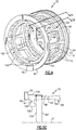
- the centering spring 70 includes first and second rings 82, 84 respectively, that are interconnected to one another by axially extending circumferentially spaced beams 86.
- the beams 86 are provided by first and second tapered portions 88, 90 joined together by a center portion 92.
- the size and shape of the beams 86 provide the desired stiffness, flexibility, and fatigue life capability of the centering spring 70.
- An aperture 94, or window, is provided between an adjacent pair of the beams 86 such that the apertures 94 are provided circumferentially between the beams 86.
- the bearing 72 is mounted to the second ring 84.
- the bearing 72 includes outer and inner races 74, 76.
- Rolling elements 78 circumferentially located by a cage 80 are provided between the outer and inner races 74, 76 respectively.
- the first ring 82 includes a radially extending flange 96.
- the flange 96 abuts a shoulder 98 of the engine static structure 36 when installed.
- the centering spring 70 may be secured to the engine static structure 36 in a variety of manners. In the example shown, a nut 100, or fastener, is used to clamp the flange 96 against the shoulder 98.
- the first ring 82 includes multiple circumferentially spaced lugs 102.
- Each of the lugs 102 axially extends into a corresponding one of the apertures 94. That is, the lugs 102 and the beams 86 are in axially overlapping relationship with one another.
- an overall axially shorter centering spring may be provided, which enables longer beams 86 to be utilized within the same space as compared to a prior art centering spring configuration. This enables additional range in centering spring stiffness and can reduce stress in the beams 86, thereby increasing part life.
- the lugs 102 include a support surface 104 that is arranged at an outer diameter.
- the beams 86 at the first ring 82 include a first radius 87 that is smaller than a second radius 105 provided at the support surface 104, that is, at the intersection of the beam 86 and the first ring 82. That is, the support surface 104 is radially proud of the beams 86. This support surface 104 engages the engine static structure 36 in a tight fit, interference relationship.
- a full hoop 108 is arranged radially inwardly of the lugs 102 to prevent the lugs 102 from bending.
- Lug pedestals 106 are circumferentially spaced apart from one another and radially interconnect the lugs 102 to the hoop 108. It should be noted full hoop 108 is not necessarily required provided lugs 102 are stiff enough to endure the various engine load and dynamic scenarios to which they are subject.
- the second ring 84 provides a sealing surface 110 with respect to the adjacent engine static structure 36.
- Axially spaced apart grooves 112 are provided in the sealing surface 110 and receive a seal 114, such as a piston ring.
- the space provided between the seals 114 provides an oil damper between the second ring 84 and the engine static structure 36. It should be noted it is not necessary to have sealing surface 110 and the associated seals 114 present in the second ring 84, yet damper oil may still be provided to the radial space between the engine static structure 36 and the second ring 84. It is also possible to not have sealing surface 110 and the associated seals 114 present in the second ring 84 and have no damper oil delivered to the radial space between the engine static structure 36 and the second ring 84.
- a bearing support surface 116 is provided by the second ring. As shown in Figures 3 and 4 , this bearing support surface 116 may be radially spaced inward from the sealing surface 110 and supported by radially extending, circumferentially spaced apart bearing pedestals 118. A notch 120 may be provided on the bearing support surface 116 to receive a retaining clip 122 that axially locates the bearing 72.
- Another bearing compartment 166 is illustrated in Figure 6 . This bearing compartment 166 includes a centering spring 170 with a flange 196 having circumferentially spaced holes 197 and configured to receive fasteners (such as bolts) 200 to secure the centering spring 170 to the engine static structure 136.
- the first ring 182 includes the support surface 204 that engages the engine static structure.
- the lugs 202 axially extend into the aperture 194 such that they are in axially overlapping relationship with the beams 186.
- the second ring 184 supports the bearing 172, which is axially retained with respect to the rotating structure 145 by a nut 226.
Landscapes
- Engineering & Computer Science (AREA)
- General Engineering & Computer Science (AREA)
- Mechanical Engineering (AREA)
- Chemical & Material Sciences (AREA)
- Combustion & Propulsion (AREA)
- Rolling Contact Bearings (AREA)
- Structures Of Non-Positive Displacement Pumps (AREA)
Abstract
Description
- The application relates to a bearing compartment for a gas turbine engine and, particularly, a centering spring used in the bearing compartment.
- Centering springs are commonly used in gas turbine engines to centrally locate rotor shafts and transmit bearing loads to engine static structure. A typical centering spring includes first and second rings that are axially spaced apart from one another and interconnected by circumferentially spaced axially extending beams. The bearing is supported by the second ring, and the first ring is mounted to the engine static structure via a tight, interference fit to the engine static structure. A support surface on the first ring providing the interference fit is axially spaced from the beams. Load from the bearing is passed through the beams, which are the flexible portion of the centering spring, to the first ring and into the engine static structure by way of the tight fit. The beams are designed to provide a desired stiffness and fatigue life capability for the centering spring.
- In accordance with a first aspect of the present invention, a bearing compartment for a gas turbine engine includes an engine static structure. A rotating structure is configured to rotate about an axis relative to the engine static structure. A bearing supports the rotating structure. A centering spring has first and second rings interconnected by axially extending circumferentially spaced beams. An aperture is provided between an adjacent pair of the beams. The first ring is mounted to the engine static structure. The bearing is mounted to the second ring. The first ring includes multiple circumferentially spaced lugs. Each of the lugs axially extend into a corresponding one of the apertures. The lugs include a support surface that engages the engine static structure.
- In an embodiment of the above, the beam has a first radius at the first ring. The lug has a second radius at the support surface. The second radius is greater than the first radius.
- In a further embodiment of any of the above, the beam is tapered and includes first and second portions respectively joined to the first and second rings. A center portion interconnects the first and second portions.
- In a further embodiment of any of the above, the first ring includes a hoop that is arranged radially inward of the lugs and joined thereto by radially extending lug pedestals.
- In a further embodiment of any of the above, the second ring provides a bearing support surface that is supported by radially extending circumferentially spaced bearing pedestals. The bearing is mounted to the bearing support surface.
- In a further embodiment of any of the above, the second ring includes a sealing surface having at least one groove. A seal is provided in the groove. The seal engages the engine static structure.
- In a further embodiment of any of the above, the first ring includes a radially extending flange that abuts a shoulder that is provided on the engine static structure. A fastener secures the flange to the engine static structure.
- In a further embodiment of any of the above, the fastener is a nut secured, via threads, to the engine static structure and in abutment with the flange.
- In a further embodiment of any of the above, the flange includes circumferentially spaced apart holes that receive bolts that fasten the flange to the engine static structure.
- In a further embodiment of any of the above, the bearing includes inner and outer races. Rolling elements are circumferentially retained with respect to one another and are arranged between the inner and outer races.
- In a further embodiment of any of the above, the outer race is discrete from the second ring.
- In a further embodiment of any of the above, the axis is an engine axis. The rotating structure is a shaft that operatively supports at least one of a turbine section and a compressor section for rotation about the axis.
- In accordance with a second aspect of the present invention, a centering spring for transferring a load from a bearing to an engine static structure, the centering spring includes first and second rings interconnected by axially extending circumferentially spaced beams. An aperture is provided between an adjacent pair of the beams. The first ring is configured to be mounted to the engine static structure. The second ring is configured to support the bearing. The first ring includes multiple circumferentially spaced lugs. Each of the lugs axially extend into a corresponding one of the apertures. The lugs include a support surface that is configured to engage the engine static structure.
- In an embodiment of the above, the beam has a first radius at the first ring. The lug has a second radius at the support surface. The second radius is greater than the first radius.
- In a further embodiment of any of the above, the beam is tapered and includes first and second portions respectively joined to the first and second rings. A center portion interconnects the first and second portions.
- In a further embodiment of any of the above, the first ring includes a hoop that is arranged radially inward of the lugs and joined thereto by radially extending lug pedestals.
- In a further embodiment of any of the above, the first ring includes a radially extending flange. The flange is configured to abut the engine static structure.
- In a further embodiment of any of the above, the flange includes circumferentially spaced apart holes that are configured to receive bolts that fasten the flange to the engine static structure.
- In a further embodiment of any of the above, the second ring provides a bearing support surface that is supported by radially extending circumferentially spaced bearing pedestals. The bearing support surface is configured to support the bearing.
- In a further embodiment of any of the above, the second ring includes a sealing surface having at least one groove. A seal is provided in the groove. The seal is configured to engage the engine static structure.
-
-
Figure 1 is a schematic cross-sectional view of an example gas turbine engine. -
Figure 2 is a schematic view of a bearing compartment shown inFigure 1 . -
Figure 3 is a cross-sectional view through a bearing compartment. -
Figure 4 is a perspective view of an example centering spring used in the bearing compartment. -
Figure 5A is a cross-sectional view of the centering spring shown inFigure 4 taken along line 5a-5a. -
Figure 5B is a cross-sectional view of the centering spring shown inFigure 4 taken along line 5b-5b. -
Figure 5C is a partial view of the centering spring as illustrated inFigure 5B . -
Figure 6 is a schematic view of another example bearing compartment using another example centering spring configuration. - These and other features may be best understood from the following drawings and specification.
-
Figure 1 schematically illustrates agas turbine engine 20. Thegas turbine engine 20 is disclosed herein as a two-spool turbofan that generally incorporates afan section 22, acompressor section 24, acombustor section 26 and aturbine section 28. Thefan section 22 drives air along a bypass flow path B in a bypass duct defined within anacelle 15, and also drives air along a core flow path C for compression and communication into thecombustor section 26 then expansion through theturbine section 28. Although depicted as a two-spool turbofan gas turbine engine in the disclosed non-limiting embodiment, it should be understood that the concepts described herein are not limited to use with two-spool turbofans as the teachings may be applied to other types of turbine engines including three-spool architectures. - The
exemplary engine 20 generally includes alow speed spool 30 and ahigh speed spool 32 mounted for rotation about an engine central longitudinal axis A relative to an enginestatic structure 36 viaseveral bearing systems 38. It should be understood that various bearingsystems 38 at various locations may alternatively or additionally be provided, and the location of bearingsystems 38 may be varied as appropriate to the application. - The
low speed spool 30 generally includes aninner shaft 40 that interconnects, a first (or low)pressure compressor 44 and a first (or low)pressure turbine 46. Theinner shaft 40 is connected to thefan 42 through a speed change mechanism, which in exemplarygas turbine engine 20 is illustrated as a gearedarchitecture 48 to drive afan 42 at a lower speed than thelow speed spool 30. Thehigh speed spool 32 includes anouter shaft 50 that interconnects a second (or high)pressure compressor 52 and a second (or high)pressure turbine 54. Acombustor 56 is arranged inexemplary gas turbine 20 between thehigh pressure compressor 52 and thehigh pressure turbine 54. Amid-turbine frame 57 of the enginestatic structure 36 may be arranged generally between thehigh pressure turbine 54 and thelow pressure turbine 46. Themid-turbine frame 57 furthersupports bearing systems 38 in theturbine section 28. Theinner shaft 40 and theouter shaft 50 are concentric and rotate via bearingsystems 38 about the engine central longitudinal axis A which is collinear with their longitudinal axes. Although depicted as a geared architecture turbofan gas turbine engine in the disclosed non-limiting embodiment, it should be understood that the concepts described herein are not limited to use with geared architecture turbofans as the teachings may be applied to other types of turbine engines including non-geared architecture two-spool and three-spool architectures. - The core airflow is compressed by the
low pressure compressor 44 then thehigh pressure compressor 52, mixed and burned with fuel in thecombustor 56, then expanded over thehigh pressure turbine 54 andlow pressure turbine 46. Themid-turbine frame 57 includesairfoils 59 which are in the core airflow path C. Theturbines low speed spool 30 andhigh speed spool 32 in response to the expansion. It will be appreciated that each of the positions of thefan section 22,compressor section 24,combustor section 26,turbine section 28, and fan drive gearedarchitecture 48 may be varied. For example, gearedarchitecture 48 may be located aft of the low pressure compressor, or aft of thecombustor section 26 or even aft ofturbine section 28, andfan 42 may be positioned forward or aft of the location of gearedarchitecture 48. - The
engine 20 in one example is a high-bypass geared aircraft engine. In a further example, theengine 20 bypass ratio is greater than about six, with an example embodiment being greater than about ten, the gearedarchitecture 48 is an epicyclic gear train, such as a planetary gear system or other gear system, with a gear reduction ratio of greater than about 2.3 and thelow pressure turbine 46 has a pressure ratio that is greater than about five. In one disclosed embodiment, theengine 20 bypass ratio is greater than about ten, the fan diameter is significantly larger than that of thelow pressure compressor 44, and thelow pressure turbine 46 has a pressure ratio that is greater than about five.Low pressure turbine 46 pressure ratio is pressure measured prior to inlet oflow pressure turbine 46 as related to the pressure at the outlet of thelow pressure turbine 46 prior to an exhaust nozzle. The gearedarchitecture 48 may be an epicycle gear train, such as a planetary gear system or other gear system, with a gear reduction ratio of greater than about 2.3:1 and less than about 5:1. It should be understood, however, that the above parameters are only exemplary of one embodiment of a geared architecture engine and that the present invention is applicable to other gas turbine engines including direct drive turbofans. - A significant amount of thrust is provided by the bypass flow B due to the high bypass ratio. The
fan section 22 of theengine 20 is designed for a particular flight condition -- typically cruise at about 0.8 Mach and about 35,000 feet (10,668 meters). The flight condition of 0.8 Mach and 35,000 ft (10,668 meters), with the engine at its best fuel consumption - also known as "bucket cruise Thrust Specific Fuel Consumption ('TSFC')" - is the industry standard parameter of lbm of fuel being burned divided by lbf of thrust the engine produces at that minimum point. "Low fan pressure ratio" is the pressure ratio across the fan blade alone, without a Fan Exit Guide Vane ("FEGV") system. The low fan pressure ratio as disclosed herein according to one non-limiting embodiment is less than about 1.45. "Low corrected fan tip speed" is the actual fan tip speed in ft/sec divided by an industry standard temperature correction of [(Tram °R) / (518.7 °R)]0.5 (where °R = K x 9/5). The "Low corrected fan tip speed" as disclosed herein according to one non-limiting embodiment is less than about 1150 ft / second (350.5 meters/second). - The
engine 20 has numerous bearingcompartments 66 having a variety of configurations depending upon the location and application within theengine 20, as shown inFigure 1 . A schematic illustration of one type ofbearing compartment 66 is shown inFigure 2 . Thebearing compartment 66 includes a rotatingstructure 45 supported for rotation about the axis A via a bearing 72 (e.g., bearingsystem 38, with momentary reference toFigure 1 ) that is supported with respect to the enginestatic structure 36 via a centeringspring 70. The centeringspring 70 andbearing 72 provide abearing support assembly 68. The rotating structure may be, for example, theinner shaft 40 or theouter shaft 50 ofFigure 1 . Thebearing 72 may be any suitable configuration, such as a ball bearing, tapered roller bearing, kneel bearing, or any other suitable configuration for the application. The centeringspring 70 is designed to provide a desired stiffness and fatigue life, while permitting some flexibility when transmitting load from the rotatingstructure 45 through the bearing 72 to the enginestatic structure 36. - Some bearing
compartments 66 have limited axial space within which to fit hardware, such as the centeringspring 70. This, in turn, limits the overall length of the centering spring, making it difficult to achieve desired packaging, desired deflection, and structural criteria relating to fatigue life requirements. To this end, the disclosed centeringspring 70 provides an arrangement in which the overall centering spring length may be reduced, if desired. - Referring to
Figure 3 , the centeringspring 70 includes first andsecond rings beams 86 are provided by first and secondtapered portions center portion 92. The size and shape of thebeams 86 provide the desired stiffness, flexibility, and fatigue life capability of the centeringspring 70. - An
aperture 94, or window, is provided between an adjacent pair of thebeams 86 such that theapertures 94 are provided circumferentially between thebeams 86. - The
bearing 72 is mounted to thesecond ring 84. In the example shown inFigure 3 , thebearing 72 includes outer andinner races Rolling elements 78 circumferentially located by acage 80 are provided between the outer andinner races - The
first ring 82 includes aradially extending flange 96. Theflange 96 abuts ashoulder 98 of the enginestatic structure 36 when installed. The centeringspring 70 may be secured to the enginestatic structure 36 in a variety of manners. In the example shown, anut 100, or fastener, is used to clamp theflange 96 against theshoulder 98. - Referring to
Figures 3 and4 , thefirst ring 82 includes multiple circumferentially spaced lugs 102. Each of thelugs 102 axially extends into a corresponding one of theapertures 94. That is, thelugs 102 and thebeams 86 are in axially overlapping relationship with one another. In this manner, an overall axially shorter centering spring may be provided, which enableslonger beams 86 to be utilized within the same space as compared to a prior art centering spring configuration. This enables additional range in centering spring stiffness and can reduce stress in thebeams 86, thereby increasing part life. - The
lugs 102 include asupport surface 104 that is arranged at an outer diameter. As shown inFigure 5C , thebeams 86 at thefirst ring 82 include afirst radius 87 that is smaller than asecond radius 105 provided at thesupport surface 104, that is, at the intersection of thebeam 86 and thefirst ring 82. That is, thesupport surface 104 is radially proud of thebeams 86. Thissupport surface 104 engages the enginestatic structure 36 in a tight fit, interference relationship. - To provide stiffness to the
lugs 102, afull hoop 108 is arranged radially inwardly of thelugs 102 to prevent thelugs 102 from bending. Lug pedestals 106 are circumferentially spaced apart from one another and radially interconnect thelugs 102 to thehoop 108. It should be notedfull hoop 108 is not necessarily required providedlugs 102 are stiff enough to endure the various engine load and dynamic scenarios to which they are subject. - In the example illustrated in
Figures 3 and4 , thesecond ring 84 provides a sealingsurface 110 with respect to the adjacent enginestatic structure 36. Axially spaced apartgrooves 112 are provided in the sealingsurface 110 and receive aseal 114, such as a piston ring. The space provided between theseals 114 provides an oil damper between thesecond ring 84 and the enginestatic structure 36. It should be noted it is not necessary to have sealingsurface 110 and the associatedseals 114 present in thesecond ring 84, yet damper oil may still be provided to the radial space between the enginestatic structure 36 and thesecond ring 84. It is also possible to not have sealingsurface 110 and the associatedseals 114 present in thesecond ring 84 and have no damper oil delivered to the radial space between the enginestatic structure 36 and thesecond ring 84. - A bearing
support surface 116 is provided by the second ring. As shown inFigures 3 and4 , this bearingsupport surface 116 may be radially spaced inward from the sealingsurface 110 and supported by radially extending, circumferentially spaced apart bearing pedestals 118. Anotch 120 may be provided on the bearingsupport surface 116 to receive aretaining clip 122 that axially locates thebearing 72. Anotherbearing compartment 166 is illustrated inFigure 6 . Thisbearing compartment 166 includes a centeringspring 170 with aflange 196 having circumferentially spacedholes 197 and configured to receive fasteners (such as bolts) 200 to secure the centeringspring 170 to the enginestatic structure 136. - The
first ring 182 includes thesupport surface 204 that engages the engine static structure. Thelugs 202 axially extend into the aperture 194 such that they are in axially overlapping relationship with thebeams 186. - The
second ring 184 supports thebearing 172, which is axially retained with respect to therotating structure 145 by anut 226. - Although an embodiment of this invention has been disclosed, a worker of ordinary skill in this art would recognize that certain modifications would come within the scope of this disclosure. For that reason, the following claims should be studied to determine the true scope and content of this disclosure.
Claims (15)
- A centering spring (70, 170) for transferring a load from a bearing (72, 172) to an engine static structure (36, 136), the centering spring (70, 170) comprising:
first and second rings (82, 182, 84, 184) interconnected by axially extending circumferentially spaced beams (86, 186), an aperture (94, 194) provided between an adjacent pair of the beams (86, 186), the first ring (82, 182) configured to be mounted to the engine static structure (36, 136), the second ring (84, 184) configured to support the bearing (72, 172), the first ring (82, 182) including multiple circumferentially spaced lugs (102, 202), each of the lugs (102, 202) axially extending into a corresponding one of the apertures (94, 194), the lugs (102, 202) including a support surface (104, 204) configured to engage the engine static structure (36, 136). - The centering spring of claim 1, wherein the beam (86, 186) has a first radius (87) at the first ring (82, 182), and the lug (102, 202) has a second radius (105) at the support surface (104, 204), the second radius (105) greater than the first radius (87).
- The centering spring of claim 1 or 2, wherein the beam (86, 186) is tapered and includes first and second portions (88, 90) respectively joined to the first and second rings (82, 182, 84, 184), and a center portion (92) interconnecting the first and second portions (88, 90).
- The centering spring of any of claims 1 to 3, wherein the first ring (82, 182) includes a hoop (108) arranged radially inward of the lugs (102, 202) and joined thereto by radially extending lug pedestals (106).
- The centering spring of any preceding claim, wherein the second ring (84, 184) provides a bearing support surface (104, 204) supported by radially extending circumferentially spaced bearing pedestals (118), the bearing support surface (104, 204) configured to support the bearing (72, 172).
- The centering spring of any preceding claim, wherein the second ring (84, 184) includes a sealing surface (110) having at least one groove (112), and a seal (114) is provided in the groove (112), the seal (114) configured to engage the engine static structure (36, 136).
- The centering spring of any preceding claim, wherein the first ring (82, 182) includes a radially extending flange (96, 196) configured to abut the engine static structure (36, 136).
- The centering spring of any preceding claim, wherein the flange (96, 196) includes circumferentially spaced apart holes (197) configured to receive bolts (200) fastening the flange (96, 196) to the engine static structure (36, 136).
- A bearing compartment (66, 166) for a gas turbine engine (20) comprising:an engine static structure (36, 136);a rotating structure (45, 145) configured to rotate about an axis (A) relative to the engine static structure (36, 136);a bearing (72, 172) supporting the rotating structure (45, 145); anda centering spring (70, 170) according to any of claims 1 to 6, wherein the first ring (82, 182) is mounted to the engine static structure (36, 136), the bearing (72, 172) is mounted to the second ring (84, 184), and the support surface (104, 204) engages the engine static structure (36, 136).
- The bearing compartment of claim 9, wherein the first ring (82, 182) includes a radially extending flange (96, 196) abutting a shoulder (98) provided on the engine static structure (36, 136), and a fastener secures the flange (96, 196) to the engine static structure (36, 136).
- The bearing compartment of claim 10, wherein the fastener is a nut (100) secured, via threads, to the engine static structure (36, 136) and in abutment with the flange (96, 196).
- The bearing compartment of claim 10, wherein the flange (96, 196) includes circumferentially spaced apart holes (197) receiving bolts (200) fastening the flange (96, 196) to the engine static structure (36, 136).
- The bearing compartment of any of claims 9 to 12, wherein the bearing (72, 172) includes inner and outer races (76, 74), and rolling elements (78) are circumferentially retained with respect to one another and arranged between the inner and outer races (76, 74).
- The bearing compartment of claim 13, wherein the outer race (74) is discrete from the second ring (84, 184).
- The bearing compartment of any of claims 9 to 14, wherein the axis (A) is an engine axis (A), and the rotating structure (45, 145) is a shaft operatively supporting at least one of a turbine section (28) and a compressor section (24) for rotation about the axis (A).
Applications Claiming Priority (1)
| Application Number | Priority Date | Filing Date | Title |
|---|---|---|---|
| US16/182,747 US20200141275A1 (en) | 2018-11-07 | 2018-11-07 | Centering spring for gas turbine engine bearing compartment |
Publications (2)
| Publication Number | Publication Date |
|---|---|
| EP3650721A1 true EP3650721A1 (en) | 2020-05-13 |
| EP3650721B1 EP3650721B1 (en) | 2021-08-25 |
Family
ID=68470243
Family Applications (1)
| Application Number | Title | Priority Date | Filing Date |
|---|---|---|---|
| EP19207194.2A Active EP3650721B1 (en) | 2018-11-07 | 2019-11-05 | Centering spring for gas turbine engine bearing compartment |
Country Status (2)
| Country | Link |
|---|---|
| US (1) | US20200141275A1 (en) |
| EP (1) | EP3650721B1 (en) |
Families Citing this family (2)
| Publication number | Priority date | Publication date | Assignee | Title |
|---|---|---|---|---|
| FR3088672B1 (en) * | 2018-11-16 | 2020-12-18 | Safran Aircraft Engines | DEVICE FOR CENTERING AND GUIDING IN ROTATION OF A ROTATING PART WITH INTERLACED ARMS |
| DE102020211754A1 (en) | 2020-09-21 | 2022-03-24 | MTU Aero Engines AG | Bearing device for a turbomachine |
Citations (2)
| Publication number | Priority date | Publication date | Assignee | Title |
|---|---|---|---|---|
| WO2015130370A2 (en) * | 2013-12-20 | 2015-09-03 | United Technologies Corporation | Bearing supports |
| EP3260667A1 (en) * | 2016-06-21 | 2017-12-27 | United Technologies Corporation | Securing a centering spring to a static structure with mounting tabs |
-
2018
- 2018-11-07 US US16/182,747 patent/US20200141275A1/en not_active Abandoned
-
2019
- 2019-11-05 EP EP19207194.2A patent/EP3650721B1/en active Active
Patent Citations (2)
| Publication number | Priority date | Publication date | Assignee | Title |
|---|---|---|---|---|
| WO2015130370A2 (en) * | 2013-12-20 | 2015-09-03 | United Technologies Corporation | Bearing supports |
| EP3260667A1 (en) * | 2016-06-21 | 2017-12-27 | United Technologies Corporation | Securing a centering spring to a static structure with mounting tabs |
Also Published As
| Publication number | Publication date |
|---|---|
| US20200141275A1 (en) | 2020-05-07 |
| EP3650721B1 (en) | 2021-08-25 |
Similar Documents
| Publication | Publication Date | Title |
|---|---|---|
| EP2975226B1 (en) | Turbine section support for a gas turbine engine | |
| US10138757B2 (en) | Bearing system for gas turbine engine | |
| US9982600B2 (en) | Pre-skewed capture plate | |
| US9695870B2 (en) | Turbomachine bearing support structure | |
| EP3620608B1 (en) | Bearing assembly with a reduced axial space self-pressurizing damper and corresponding method for maintaining pressure in said damper | |
| US11560852B2 (en) | Fan drive gear system | |
| EP3000988A1 (en) | Fan drive gear system | |
| US10746049B2 (en) | Gas turbine engine case including bearing compartment | |
| EP3524797A2 (en) | Piloted retaining plate for a face seal arrangement | |
| EP3048259A1 (en) | Gas turbine engine mid-turbine frame tie rod arrangement | |
| EP3825532A1 (en) | Geared architecture for gas turbine engine | |
| EP3650721B1 (en) | Centering spring for gas turbine engine bearing compartment | |
| EP3708791A1 (en) | Integrated fan inlet case and bearing support for a gas turbine engine | |
| EP3835606A1 (en) | Curved beam centering spring for a thrust bearing | |
| EP3816472A1 (en) | Axially rigid curved beam with squeeze damper | |
| EP3282101B1 (en) | Shim for gas turbine engine | |
| EP3825575B1 (en) | Geared architecture for gas turbine engine | |
| US20140090397A1 (en) | Bleed tube attachment | |
| EP3000989B1 (en) | Fan drive gear system | |
| EP3760841B1 (en) | Multi-purpose anti-rotation lock pin | |
| EP3816410A1 (en) | Unified curved beam bearing damper | |
| EP3626935B1 (en) | A speed change mechanism for a gas turbine engine |
Legal Events
| Date | Code | Title | Description |
|---|---|---|---|
| PUAI | Public reference made under article 153(3) epc to a published international application that has entered the european phase |
Free format text: ORIGINAL CODE: 0009012 |
|
| STAA | Information on the status of an ep patent application or granted ep patent |
Free format text: STATUS: THE APPLICATION HAS BEEN PUBLISHED |
|
| AK | Designated contracting states |
Kind code of ref document: A1 Designated state(s): AL AT BE BG CH CY CZ DE DK EE ES FI FR GB GR HR HU IE IS IT LI LT LU LV MC MK MT NL NO PL PT RO RS SE SI SK SM TR |
|
| AX | Request for extension of the european patent |
Extension state: BA ME |
|
| STAA | Information on the status of an ep patent application or granted ep patent |
Free format text: STATUS: REQUEST FOR EXAMINATION WAS MADE |
|
| 17P | Request for examination filed |
Effective date: 20201110 |
|
| RBV | Designated contracting states (corrected) |
Designated state(s): AL AT BE BG CH CY CZ DE DK EE ES FI FR GB GR HR HU IE IS IT LI LT LU LV MC MK MT NL NO PL PT RO RS SE SI SK SM TR |
|
| GRAP | Despatch of communication of intention to grant a patent |
Free format text: ORIGINAL CODE: EPIDOSNIGR1 |
|
| STAA | Information on the status of an ep patent application or granted ep patent |
Free format text: STATUS: GRANT OF PATENT IS INTENDED |
|
| RAP1 | Party data changed (applicant data changed or rights of an application transferred) |
Owner name: RAYTHEON TECHNOLOGIES CORPORATION |
|
| INTG | Intention to grant announced |
Effective date: 20210305 |
|
| GRAS | Grant fee paid |
Free format text: ORIGINAL CODE: EPIDOSNIGR3 |
|
| GRAA | (expected) grant |
Free format text: ORIGINAL CODE: 0009210 |
|
| STAA | Information on the status of an ep patent application or granted ep patent |
Free format text: STATUS: THE PATENT HAS BEEN GRANTED |
|
| AK | Designated contracting states |
Kind code of ref document: B1 Designated state(s): AL AT BE BG CH CY CZ DE DK EE ES FI FR GB GR HR HU IE IS IT LI LT LU LV MC MK MT NL NO PL PT RO RS SE SI SK SM TR |
|
| REG | Reference to a national code |
Ref country code: CH Ref legal event code: EP |
|
| REG | Reference to a national code |
Ref country code: IE Ref legal event code: FG4D Ref country code: AT Ref legal event code: REF Ref document number: 1424089 Country of ref document: AT Kind code of ref document: T Effective date: 20210915 |
|
| REG | Reference to a national code |
Ref country code: DE Ref legal event code: R096 Ref document number: 602019007148 Country of ref document: DE |
|
| REG | Reference to a national code |
Ref country code: LT Ref legal event code: MG9D |
|
| REG | Reference to a national code |
Ref country code: NL Ref legal event code: MP Effective date: 20210825 |
|
| REG | Reference to a national code |
Ref country code: AT Ref legal event code: MK05 Ref document number: 1424089 Country of ref document: AT Kind code of ref document: T Effective date: 20210825 |
|
| PG25 | Lapsed in a contracting state [announced via postgrant information from national office to epo] |
Ref country code: ES Free format text: LAPSE BECAUSE OF FAILURE TO SUBMIT A TRANSLATION OF THE DESCRIPTION OR TO PAY THE FEE WITHIN THE PRESCRIBED TIME-LIMIT Effective date: 20210825 Ref country code: SE Free format text: LAPSE BECAUSE OF FAILURE TO SUBMIT A TRANSLATION OF THE DESCRIPTION OR TO PAY THE FEE WITHIN THE PRESCRIBED TIME-LIMIT Effective date: 20210825 Ref country code: RS Free format text: LAPSE BECAUSE OF FAILURE TO SUBMIT A TRANSLATION OF THE DESCRIPTION OR TO PAY THE FEE WITHIN THE PRESCRIBED TIME-LIMIT Effective date: 20210825 Ref country code: FI Free format text: LAPSE BECAUSE OF FAILURE TO SUBMIT A TRANSLATION OF THE DESCRIPTION OR TO PAY THE FEE WITHIN THE PRESCRIBED TIME-LIMIT Effective date: 20210825 Ref country code: HR Free format text: LAPSE BECAUSE OF FAILURE TO SUBMIT A TRANSLATION OF THE DESCRIPTION OR TO PAY THE FEE WITHIN THE PRESCRIBED TIME-LIMIT Effective date: 20210825 Ref country code: NO Free format text: LAPSE BECAUSE OF FAILURE TO SUBMIT A TRANSLATION OF THE DESCRIPTION OR TO PAY THE FEE WITHIN THE PRESCRIBED TIME-LIMIT Effective date: 20211125 Ref country code: PT Free format text: LAPSE BECAUSE OF FAILURE TO SUBMIT A TRANSLATION OF THE DESCRIPTION OR TO PAY THE FEE WITHIN THE PRESCRIBED TIME-LIMIT Effective date: 20211227 Ref country code: BG Free format text: LAPSE BECAUSE OF FAILURE TO SUBMIT A TRANSLATION OF THE DESCRIPTION OR TO PAY THE FEE WITHIN THE PRESCRIBED TIME-LIMIT Effective date: 20211125 Ref country code: AT Free format text: LAPSE BECAUSE OF FAILURE TO SUBMIT A TRANSLATION OF THE DESCRIPTION OR TO PAY THE FEE WITHIN THE PRESCRIBED TIME-LIMIT Effective date: 20210825 Ref country code: LT Free format text: LAPSE BECAUSE OF FAILURE TO SUBMIT A TRANSLATION OF THE DESCRIPTION OR TO PAY THE FEE WITHIN THE PRESCRIBED TIME-LIMIT Effective date: 20210825 |
|
| PG25 | Lapsed in a contracting state [announced via postgrant information from national office to epo] |
Ref country code: PL Free format text: LAPSE BECAUSE OF FAILURE TO SUBMIT A TRANSLATION OF THE DESCRIPTION OR TO PAY THE FEE WITHIN THE PRESCRIBED TIME-LIMIT Effective date: 20210825 Ref country code: LV Free format text: LAPSE BECAUSE OF FAILURE TO SUBMIT A TRANSLATION OF THE DESCRIPTION OR TO PAY THE FEE WITHIN THE PRESCRIBED TIME-LIMIT Effective date: 20210825 Ref country code: GR Free format text: LAPSE BECAUSE OF FAILURE TO SUBMIT A TRANSLATION OF THE DESCRIPTION OR TO PAY THE FEE WITHIN THE PRESCRIBED TIME-LIMIT Effective date: 20211126 |
|
| PG25 | Lapsed in a contracting state [announced via postgrant information from national office to epo] |
Ref country code: NL Free format text: LAPSE BECAUSE OF FAILURE TO SUBMIT A TRANSLATION OF THE DESCRIPTION OR TO PAY THE FEE WITHIN THE PRESCRIBED TIME-LIMIT Effective date: 20210825 |
|
| PG25 | Lapsed in a contracting state [announced via postgrant information from national office to epo] |
Ref country code: DK Free format text: LAPSE BECAUSE OF FAILURE TO SUBMIT A TRANSLATION OF THE DESCRIPTION OR TO PAY THE FEE WITHIN THE PRESCRIBED TIME-LIMIT Effective date: 20210825 |
|
| REG | Reference to a national code |
Ref country code: DE Ref legal event code: R097 Ref document number: 602019007148 Country of ref document: DE |
|
| PG25 | Lapsed in a contracting state [announced via postgrant information from national office to epo] |
Ref country code: SM Free format text: LAPSE BECAUSE OF FAILURE TO SUBMIT A TRANSLATION OF THE DESCRIPTION OR TO PAY THE FEE WITHIN THE PRESCRIBED TIME-LIMIT Effective date: 20210825 Ref country code: SK Free format text: LAPSE BECAUSE OF FAILURE TO SUBMIT A TRANSLATION OF THE DESCRIPTION OR TO PAY THE FEE WITHIN THE PRESCRIBED TIME-LIMIT Effective date: 20210825 Ref country code: RO Free format text: LAPSE BECAUSE OF FAILURE TO SUBMIT A TRANSLATION OF THE DESCRIPTION OR TO PAY THE FEE WITHIN THE PRESCRIBED TIME-LIMIT Effective date: 20210825 Ref country code: EE Free format text: LAPSE BECAUSE OF FAILURE TO SUBMIT A TRANSLATION OF THE DESCRIPTION OR TO PAY THE FEE WITHIN THE PRESCRIBED TIME-LIMIT Effective date: 20210825 Ref country code: CZ Free format text: LAPSE BECAUSE OF FAILURE TO SUBMIT A TRANSLATION OF THE DESCRIPTION OR TO PAY THE FEE WITHIN THE PRESCRIBED TIME-LIMIT Effective date: 20210825 Ref country code: AL Free format text: LAPSE BECAUSE OF FAILURE TO SUBMIT A TRANSLATION OF THE DESCRIPTION OR TO PAY THE FEE WITHIN THE PRESCRIBED TIME-LIMIT Effective date: 20210825 |
|
| PG25 | Lapsed in a contracting state [announced via postgrant information from national office to epo] |
Ref country code: MC Free format text: LAPSE BECAUSE OF FAILURE TO SUBMIT A TRANSLATION OF THE DESCRIPTION OR TO PAY THE FEE WITHIN THE PRESCRIBED TIME-LIMIT Effective date: 20210825 |
|
| PLBE | No opposition filed within time limit |
Free format text: ORIGINAL CODE: 0009261 |
|
| STAA | Information on the status of an ep patent application or granted ep patent |
Free format text: STATUS: NO OPPOSITION FILED WITHIN TIME LIMIT |
|
| PG25 | Lapsed in a contracting state [announced via postgrant information from national office to epo] |
Ref country code: LU Free format text: LAPSE BECAUSE OF NON-PAYMENT OF DUE FEES Effective date: 20211105 Ref country code: IT Free format text: LAPSE BECAUSE OF FAILURE TO SUBMIT A TRANSLATION OF THE DESCRIPTION OR TO PAY THE FEE WITHIN THE PRESCRIBED TIME-LIMIT Effective date: 20210825 Ref country code: BE Free format text: LAPSE BECAUSE OF NON-PAYMENT OF DUE FEES Effective date: 20211130 |
|
| REG | Reference to a national code |
Ref country code: BE Ref legal event code: MM Effective date: 20211130 |
|
| 26N | No opposition filed |
Effective date: 20220527 |
|
| PG25 | Lapsed in a contracting state [announced via postgrant information from national office to epo] |
Ref country code: SI Free format text: LAPSE BECAUSE OF FAILURE TO SUBMIT A TRANSLATION OF THE DESCRIPTION OR TO PAY THE FEE WITHIN THE PRESCRIBED TIME-LIMIT Effective date: 20210825 |
|
| PG25 | Lapsed in a contracting state [announced via postgrant information from national office to epo] |
Ref country code: IE Free format text: LAPSE BECAUSE OF NON-PAYMENT OF DUE FEES Effective date: 20211105 |
|
| P01 | Opt-out of the competence of the unified patent court (upc) registered |
Effective date: 20230521 |
|
| PG25 | Lapsed in a contracting state [announced via postgrant information from national office to epo] |
Ref country code: CY Free format text: LAPSE BECAUSE OF FAILURE TO SUBMIT A TRANSLATION OF THE DESCRIPTION OR TO PAY THE FEE WITHIN THE PRESCRIBED TIME-LIMIT Effective date: 20210825 |
|
| REG | Reference to a national code |
Ref country code: CH Ref legal event code: PL |
|
| PG25 | Lapsed in a contracting state [announced via postgrant information from national office to epo] |
Ref country code: LI Free format text: LAPSE BECAUSE OF NON-PAYMENT OF DUE FEES Effective date: 20221130 Ref country code: HU Free format text: LAPSE BECAUSE OF FAILURE TO SUBMIT A TRANSLATION OF THE DESCRIPTION OR TO PAY THE FEE WITHIN THE PRESCRIBED TIME-LIMIT; INVALID AB INITIO Effective date: 20191105 Ref country code: CH Free format text: LAPSE BECAUSE OF NON-PAYMENT OF DUE FEES Effective date: 20221130 |
|
| PGFP | Annual fee paid to national office [announced via postgrant information from national office to epo] |
Ref country code: GB Payment date: 20231019 Year of fee payment: 5 |
|
| PGFP | Annual fee paid to national office [announced via postgrant information from national office to epo] |
Ref country code: FR Payment date: 20231019 Year of fee payment: 5 Ref country code: DE Payment date: 20231019 Year of fee payment: 5 |
|
| PG25 | Lapsed in a contracting state [announced via postgrant information from national office to epo] |
Ref country code: MK Free format text: LAPSE BECAUSE OF FAILURE TO SUBMIT A TRANSLATION OF THE DESCRIPTION OR TO PAY THE FEE WITHIN THE PRESCRIBED TIME-LIMIT Effective date: 20210825 |
|
| PG25 | Lapsed in a contracting state [announced via postgrant information from national office to epo] |
Ref country code: TR Free format text: LAPSE BECAUSE OF FAILURE TO SUBMIT A TRANSLATION OF THE DESCRIPTION OR TO PAY THE FEE WITHIN THE PRESCRIBED TIME-LIMIT Effective date: 20210825 |