EP3650676B1 - Fuel flow control system and method for engine start - Google Patents
Fuel flow control system and method for engine start Download PDFInfo
- Publication number
- EP3650676B1 EP3650676B1 EP19207548.9A EP19207548A EP3650676B1 EP 3650676 B1 EP3650676 B1 EP 3650676B1 EP 19207548 A EP19207548 A EP 19207548A EP 3650676 B1 EP3650676 B1 EP 3650676B1
- Authority
- EP
- European Patent Office
- Prior art keywords
- fuel
- engine
- flameout
- schedule
- injected
- Prior art date
- Legal status (The legal status is an assumption and is not a legal conclusion. Google has not performed a legal analysis and makes no representation as to the accuracy of the status listed.)
- Active
Links
- 239000000446 fuel Substances 0.000 title claims description 192
- 238000000034 method Methods 0.000 title claims description 29
- 230000001133 acceleration Effects 0.000 claims description 28
- 238000012545 processing Methods 0.000 claims description 25
- 238000012544 monitoring process Methods 0.000 claims description 14
- 230000004044 response Effects 0.000 claims description 5
- 239000007789 gas Substances 0.000 description 12
- 239000003570 air Substances 0.000 description 8
- 238000002347 injection Methods 0.000 description 7
- 239000007924 injection Substances 0.000 description 7
- 230000008569 process Effects 0.000 description 6
- 238000004401 flow injection analysis Methods 0.000 description 5
- 238000002485 combustion reaction Methods 0.000 description 4
- 230000006870 function Effects 0.000 description 3
- 239000000203 mixture Substances 0.000 description 3
- 239000012080 ambient air Substances 0.000 description 2
- 239000000567 combustion gas Substances 0.000 description 2
- 238000004891 communication Methods 0.000 description 2
- 238000001514 detection method Methods 0.000 description 2
- 238000010586 diagram Methods 0.000 description 2
- 238000012986 modification Methods 0.000 description 2
- 230000004048 modification Effects 0.000 description 2
- 230000006399 behavior Effects 0.000 description 1
- 230000008033 biological extinction Effects 0.000 description 1
- 230000003247 decreasing effect Effects 0.000 description 1
- 238000005259 measurement Methods 0.000 description 1
- 230000003287 optical effect Effects 0.000 description 1
- 238000012552 review Methods 0.000 description 1
- 239000004065 semiconductor Substances 0.000 description 1
- 239000007858 starting material Substances 0.000 description 1
- 230000003068 static effect Effects 0.000 description 1
Images


Classifications
-
- F—MECHANICAL ENGINEERING; LIGHTING; HEATING; WEAPONS; BLASTING
- F02—COMBUSTION ENGINES; HOT-GAS OR COMBUSTION-PRODUCT ENGINE PLANTS
- F02C—GAS-TURBINE PLANTS; AIR INTAKES FOR JET-PROPULSION PLANTS; CONTROLLING FUEL SUPPLY IN AIR-BREATHING JET-PROPULSION PLANTS
- F02C9/00—Controlling gas-turbine plants; Controlling fuel supply in air- breathing jet-propulsion plants
- F02C9/26—Control of fuel supply
-
- F—MECHANICAL ENGINEERING; LIGHTING; HEATING; WEAPONS; BLASTING
- F02—COMBUSTION ENGINES; HOT-GAS OR COMBUSTION-PRODUCT ENGINE PLANTS
- F02C—GAS-TURBINE PLANTS; AIR INTAKES FOR JET-PROPULSION PLANTS; CONTROLLING FUEL SUPPLY IN AIR-BREATHING JET-PROPULSION PLANTS
- F02C7/00—Features, components parts, details or accessories, not provided for in, or of interest apart form groups F02C1/00 - F02C6/00; Air intakes for jet-propulsion plants
- F02C7/26—Starting; Ignition
- F02C7/262—Restarting after flame-out
-
- F—MECHANICAL ENGINEERING; LIGHTING; HEATING; WEAPONS; BLASTING
- F02—COMBUSTION ENGINES; HOT-GAS OR COMBUSTION-PRODUCT ENGINE PLANTS
- F02C—GAS-TURBINE PLANTS; AIR INTAKES FOR JET-PROPULSION PLANTS; CONTROLLING FUEL SUPPLY IN AIR-BREATHING JET-PROPULSION PLANTS
- F02C3/00—Gas-turbine plants characterised by the use of combustion products as the working fluid
- F02C3/04—Gas-turbine plants characterised by the use of combustion products as the working fluid having a turbine driving a compressor
- F02C3/06—Gas-turbine plants characterised by the use of combustion products as the working fluid having a turbine driving a compressor the compressor comprising only axial stages
-
- F—MECHANICAL ENGINEERING; LIGHTING; HEATING; WEAPONS; BLASTING
- F02—COMBUSTION ENGINES; HOT-GAS OR COMBUSTION-PRODUCT ENGINE PLANTS
- F02C—GAS-TURBINE PLANTS; AIR INTAKES FOR JET-PROPULSION PLANTS; CONTROLLING FUEL SUPPLY IN AIR-BREATHING JET-PROPULSION PLANTS
- F02C7/00—Features, components parts, details or accessories, not provided for in, or of interest apart form groups F02C1/00 - F02C6/00; Air intakes for jet-propulsion plants
- F02C7/26—Starting; Ignition
-
- F—MECHANICAL ENGINEERING; LIGHTING; HEATING; WEAPONS; BLASTING
- F05—INDEXING SCHEMES RELATING TO ENGINES OR PUMPS IN VARIOUS SUBCLASSES OF CLASSES F01-F04
- F05D—INDEXING SCHEME FOR ASPECTS RELATING TO NON-POSITIVE-DISPLACEMENT MACHINES OR ENGINES, GAS-TURBINES OR JET-PROPULSION PLANTS
- F05D2220/00—Application
- F05D2220/30—Application in turbines
- F05D2220/32—Application in turbines in gas turbines
-
- F—MECHANICAL ENGINEERING; LIGHTING; HEATING; WEAPONS; BLASTING
- F05—INDEXING SCHEMES RELATING TO ENGINES OR PUMPS IN VARIOUS SUBCLASSES OF CLASSES F01-F04
- F05D—INDEXING SCHEME FOR ASPECTS RELATING TO NON-POSITIVE-DISPLACEMENT MACHINES OR ENGINES, GAS-TURBINES OR JET-PROPULSION PLANTS
- F05D2270/00—Control
- F05D2270/01—Purpose of the control system
- F05D2270/09—Purpose of the control system to cope with emergencies
- F05D2270/092—Purpose of the control system to cope with emergencies in particular blow-out and relight
Definitions
- the present disclosure relates generally to fuel flow control for engine start.
- a method for controlling fuel flow to an engine during start comprises causing fuel to be injected into a combustor of the engine according to a first fuel schedule defining a minimum fuel flow limit required to achieve light-off of the engine, the minimum fuel flow limit set at an initial value, monitoring, following light-off of the engine, at least one operating parameter of the engine, detecting, based on the at least one operating parameter, occurrence of flameout in the engine, and, in response to detecting occurrence of flameout in the engine, increasing the minimum fuel flow limit from the initial value to a first value to obtain an adjusted fuel schedule, and causing fuel to be injected into the combustor according to the adjusted fuel schedule.
- the first fuel schedule follows an open loop profile.
- monitoring the at least one operating parameter of the engine comprises monitoring an acceleration of the engine, and detecting the presence of the flameout condition comprises comparing the acceleration to a predetermined threshold and detecting partial flameout responsive to determining that the acceleration is below the threshold.
- the first fuel schedule defines a maximum fuel flow limit, and the first value is lower than the maximum fuel flow limit.
- the method further comprises, after causing fuel to be injected according to the adjusted fuel schedule: detecting occurrence of a subsequent flameout in the engine, increasing the minimum fuel flow limit from the first value to a second value lower than the maximum fuel flow limit to obtain a newly adjusted fuel schedule, and causing fuel to be injected into the combustor according to the newly adjusted fuel schedule.
- detecting occurrence of flameout in the engine comprises detecting occurrence of a partial flameout.
- detecting occurrence of flameout in the engine comprises detecting occurrence of a complete flameout.
- fuel is caused to be injected into the combustor according to the adjusted fuel schedule with the engine on the ground.
- fuel is caused to be injected into the combustor according to the adjusted fuel schedule while in flight.
- a system for controlling fuel flow to an engine during start comprises at least one processing unit and at least one non-transitory computer-readable memory having stored thereon program instructions executable by the at least one processing unit for causing fuel to be injected into a combustor of the engine according to a first fuel schedule defining a minimum fuel flow limit required to achieve light-off of the engine, the minimum fuel flow limit set at an initial value, monitoring, following light-off of the engine, at least one operating parameter of the engine, detecting, based on the at least one operating parameter, occurrence of flameout in the engine, and, in response to detecting occurrence of flameout in the engine, increasing the minimum fuel flow limit from the initial value to a first value to obtain an adjusted fuel schedule, and causing fuel to be injected into the combustor according to the adjusted fuel schedule.
- the program instructions are executable by the at least one processing unit for causing fuel to be injected into the combustor according to the first fuel schedule following an open loop profile.
- the program instructions are executable by the at least one processing unit for monitoring the at least one operating parameter of the engine comprising monitoring an acceleration of the engine, and for detecting the presence of the flameout condition comprising comparing the acceleration of the engine to a predetermined threshold and detecting partial flameout responsive to determining that the acceleration is below the threshold.
- the program instructions are executable by the at least one processing unit for causing fuel to be injected into the combustor according to the first fuel schedule defining a maximum fuel flow limit, the first value being lower than the maximum fuel flow limit.
- the program instructions are executable by the at least one processing unit for, after causing fuel to be injected according to the adjusted fuel schedule: detecting occurrence of a subsequent flameout in the engine, increasing the minimum fuel flow limit from the first value to a second value lower than the maximum fuel flow limit to obtain a newly adjusted fuel schedule, and causing fuel to be injected into the combustor according to the newly adjusted fuel schedule.
- the program instructions are executable by the at least one processing unit for detecting occurrence of flameout in the engine comprising detecting occurrence of a partial flameout.
- the program instructions are executable by the at least one processing unit for detecting occurrence of flameout in the engine comprising detecting occurrence of a complete flameout.
- the program instructions are executable by the at least one processing unit for causing fuel to be injected into the combustor according to the adjusted fuel schedule with the engine on the ground.
- the program instructions are executable by the at least one processing unit for causing fuel to be injected into the combustor according to the adjusted fuel schedule while in flight.
- a non-transitory computer readable medium having stored thereon program code executable by at least one processor for causing fuel to be injected into a combustor of the engine according to a first fuel schedule defining a minimum fuel flow limit required to achieve light-off of the engine, the minimum fuel flow limit set at an initial value, monitoring, following light-off of the engine, at least one operating parameter of the engine, detecting, based on the at least one operating parameter, occurrence of flameout in the engine, and, in response to detecting occurrence of flameout the engine, increasing the minimum fuel flow limit from the initial value to a first value to obtain an adjusted fuel schedule, and causing fuel to be injected into the combustor according to the adjusted fuel schedule.
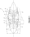
- Figure 1 illustrates a gas turbine engine 10 of a type preferably provided for use in subsonic flight, generally comprising in serial flow communication, a fan 12 through which ambient air is propelled, a compressor section 14 for pressurizing the air, a combustor 16 in which the compressed air is mixed with fuel and ignited for generating an annular stream of hot combustion gases, and a turbine section 18 for extracting energy from the combustion gases.
- High pressure rotor(s) 20 of the turbine section 18 are drivingly engaged to high pressure rotor(s) 22 of the compressor section 14 through a high pressure shaft 24.
- Low pressure rotor(s) 26 of the turbine section 18 are drivingly engaged to the fan rotor 12 and to other low pressure rotor(s) (not shown) of the compressor section 14 through a low pressure shaft 28 extending within the high pressure shaft 24 and rotating independently therefrom.
- gas turbine engine 10 may alternatively be another type of engine, for example a turboshaft engine, also generally comprising in serial flow communication a compressor section, a combustor, and a turbine section, and a fan through which ambient air is propelled.
- a turboprop engine may also apply.
- the engine 10 is described herein for flight applications, it should be understood that other uses, such as industrial or the like, may apply.
- the starting (or start-up) process of the gas turbine engine 10 illustratively comprises two consecutive phases.
- the high pressure rotor(s) 22 of the compressor section 14 are rotated by a torque provided by an external source, such as a starter (not shown), in order to provide air flow into the combustor 16.
- an external source such as a starter (not shown)
- fuel flow is then injected into the combustor 16 at a controlled rate.
- an electronic engine controller (EEC) 202 illustratively outputs one or more control signals to a fuel control unit 204 to cause the injection of fuel flow.
- the fuel control unit 204 comprises a fuel pump and a stepper (not shown), a torque motor valve (not shown), or any suitable equivalent means for injecting fuel into the combustor 16.
- the EEC 202 may be part of a Full Authority Digital Engine Control (FADEC), which is used to control the operation and performance of the engine 10.
- FADEC Full Authority Digital Engine Control
- the EEC 202 selects the appropriate fuel schedule for the light-off procedure by querying a memory storing one or more fuel schedules.
- the memory may also store therein all data (e.g., engine operating parameters) sensed or measured as well as other predetermined data and programs.
- the fuel schedule which is selected in the first phase of the engine starting process, follows an open loop fuel flow profile in which fuel flow is commanded based on a desired rotational speed of the compressor section 14.
- the fuel schedule may thus be referred to herein as an "open loop fuel schedule" and the first phase may be referred to as direct fuel flow control.
- the fuel flow is injected to mix with the air flow and the mixture is then exposed to an ignition source (e.g., a spark igniter, not shown).
- an ignition source e.g., a spark igniter, not shown.
- Light-off of the combustion process occurs in the combustor 16 when an appropriate fuel/air ratio is reached, resulting in ignition of the engine 10.
- the light-off occurrence is detected by monitoring an exhaust temperature of the engine 10, with light-off being detected when the exhaust temperature reaches a threshold temperature (e.g., 200 °F (93.3°C)).
- the inter-stage turbine temperature (ITT) which is the temperature of the exhaust gases between the high and low pressure turbines of the engine 10, is used as the exhaust temperature.
- the exhaust temperature may be monitored using a temperature sensor (not shown) associated with an exhaust outlet (not shown) of the engine 10.
- an ultraviolet or photoelectric signal which may be generated by any suitable flame detection measurement system and indicates the presence of visible flames at the exhaust outlet of the engine 10, may be monitored by the EEC 202 to detect light-off.
- light-off can be detected following a predetermined increase in the inter-stage turbine temperature.
- light-off is detected when the gas generator (i.e. engine) speed reaches a predetermined value. Other embodiments may apply.
- the fuel flow is continuously injected into the combustor 16, thus enabling local ignition to propagate and spread so as to form stable combustion in the combustor 16.
- the speed of the engine 10 is then accelerated by increasing the injection of fuel flow until the engine 10 operates under a self-sustained speed.
- the fuel flow is injected according to a fuel schedule required for operation of the engine 10 from light-off to a self-sustaining condition.
- the appropriate fuel schedule is selected by the EEC 202.
- the fuel schedule follows a closed loop fuel profile in which fuel flow is commanded to achieve a desired acceleration of the compressor section 14.
- the fuel schedule may thus be referred to herein as a "closed loop fuel schedule" and the second phase may be referred to as sub-idle acceleration governing or closed loop sub-idle acceleration scheduling.
- the EEC 202 is used to adjust fuel flow to the combustor 16 upon detection of engine flameout during start of the engine 10. It should be understood that the engine start may occur in-flight or on the ground.
- flameout refers to the run-down of the engine 10 that may be caused by the extinction of the flame in chamber(s) of the combustor 16. During engine flameout, the combustor 16 does not burn all of the fuel supplied to it, which in turn reduces the overall engine performance and efficiency. When flameout only occurs in some, but not all, (i.e. a subset of) chambers of the combustor 16, it is referred to as "partial flameout".
- flameout condition For engines having a single combustion chamber, partial flameout is observed when flameout occurs in a section of the chamber. When flameout occurs in all chambers of the combustor 16, it is referred to as “complete flameout” or “full flameout”. As known to those skilled in the art, flameout may be caused by high velocity air entering the engine 10. Flameout may also be caused by improper fuel-air mixture or interruption of the airflow through the engine 10. This may be the result of a given engine operating condition, such as acceleration of the engine 10 decreasing below a predetermined threshold. As used herein, the term “flameout condition” thus refers to an operating condition of the engine 10 that, if not corrected, results in flameout.
- the methods e.g., implemented by the EEC 202 and systems described herein are used during high speed in-flight restart.
- the EEC 202 is configured to detect engine flameout following light-off of the engine 10 and to accordingly increase the minimum (e.g., open loop) fuel flow injection into the combustor 16 to avoid a subsequent partial or complete flameout.
- FIG 3 is an example embodiment of a computing device 300 for implementing the EEC 202 described above with reference to Figure 2 .
- the computing device 300 comprises a processing unit 302 and a memory 304 which has stored therein computer-executable instructions 306.
- the processing unit 302 may comprise any suitable devices configured to cause a series of steps to be performed such that instructions 306, when executed by the computing device 300 or other programmable apparatus, may cause the functions/acts/steps specified in the method described herein to be executed.
- the processing unit 302 may comprise, for example, any type of general-purpose microprocessor or microcontroller, a digital signal processing (DSP) processor, a CPU, an integrated circuit, a field programmable gate array (FPGA), a reconfigurable processor, other suitably programmed or programmable logic circuits, or any combination thereof.
- DSP digital signal processing
- FPGA field programmable gate array
- reconfigurable processor other suitably programmed or programmable logic circuits, or any combination thereof.
- the memory 304 may comprise any suitable known or other machine-readable storage medium.
- the memory 304 may comprise non-transitory computer readable storage medium, for example, but not limited to, an electronic, magnetic, optical, electromagnetic, infrared, or semiconductor system, apparatus, or device, or any suitable combination of the foregoing.
- the memory 304 may include a suitable combination of any type of computer memory that is located either internally or externally to device, for example random-access memory (RAM), read-only memory (ROM), electro-optical memory, magneto-optical memory, erasable programmable read-only memory (EPROM), and electrically-erasable programmable read-only memory (EEPROM), Ferroelectric RAM (FRAM) or the like.
- Memory 304 may comprise any storage means (e.g., devices) suitable for retrievably storing machine-readable instructions 306 executable by processing unit 302.
- the method 400 may be implemented by the EEC 202 of Figure 2 , i.e. by the computing device 300 of Figure 3 .
- the method 400 comprises, at step 402, causing fuel injection into the combustor (reference 16 in Figure 1 ) in order to achieve light-off.
- step 402 may comprise the EEC 202 outputting to the fuel control unit (reference 204 in Figure 2 ) control signal(s) comprising instructions to cause the fuel control unit to inject the fuel flow to the combustor, according to a given fuel schedule.
- One or more schedules may be stored in memory (reference 304 in Figure 3 ) in any suitable format (e.g.
- the EEC 202 illustratively queries the memory to select the fuel schedule that is appropriate for light-off.
- the appropriate fuel schedule follows an open loop fuel flow profile.
- the fuel schedule illustratively defines a minimum fuel flow limit and a maximum fuel flow limit, the minimum and maximum fuel flow limit each set at an initial value also stored in the memory.
- the minimum and maximum fuel flow limits illustratively correspond to an amount of fuel injected into the combustor 16.
- one or more engine operating parameters are monitored at step 404 to detect engine flameout.
- the one or more operating parameters are monitored with the engine 10 operating in the closed loop sub-idle acceleration scheduling.
- the acceleration of the engine 10 is monitored at step 404.
- the engine operating parameter(s) monitored at step 404 may also include, but are not limited to, inter-stage turbine temperature.
- An assessment as to whether engine flameout, whether partial or complete, is detected is then made at step 406, based on the engine operating parameter(s) monitored at step 404. For example, if acceleration of the engine 10 is monitored at step 404, step 406 may comprise comparing the acceleration to a threshold value. If it is determined that the acceleration is below the threshold value, partial flameout is detected.
- the method 400 may end. Otherwise, if engine flameout is detected at step 406, the next step 408 is to adjust the open loop fuel schedule by increasing fuel flow injection by a predetermined amount.
- the predetermined amount of fuel injection increase may vary depending on engine configuration (e.g., depending on factors including, but not limited to, gas generator speed, altitude, temperature, and number of partial flameouts detected during engine start).
- the initial value of the minimum fuel flow limit associated with the open loop fuel schedule is increased by the predetermined amount so as to set the minimum fuel flow limit at a first adjusted value, which is lower than the maximum fuel flow limit.
- a first adjusted fuel schedule is thus obtained.
- the EEC 202 may then output one or more control signals to cause fuel flow to be injected into the combustor, e.g., when the engine restarts, according to the first adjusted fuel schedule.
- next step 410 is to cause fuel flow injection into the combustor.
- the engine 10 may be recovered from flameout.
- Steps 404 to 410 are then repeated and engine parameter(s) are monitored again at step 404 to detect any subsequent engine flameout (step 406). If it is determined at step 406 that no subsequent engine flameout has been detected, the method 400 may end. Otherwise, the fuel injection is increased again at step 408, by a same or different amount as previously and up to a pre-determined limit. For this purpose, the value of the minimum fuel flow limit is increased from the first adjusted value to a second adjusted value lower than the maximum fuel flow limit.
- a second adjusted fuel schedule is thus obtained and the EEC 202 may then output one or more control signals to cause fuel flow to be injected into the combustor, e.g., when the engine restarts, according to the second adjusted fuel schedule.
- the method 400 may then proceed again to step 410.
- the process of adjusting the open loop fuel schedule e.g., steps 404 to 408 may be repeated every time engine flameout is detected, up to a pre-determined limit (e.g. a maximum fuel flow limit or a maximum number of fuel flow increases). It should also be understood that once the pre-determined limit is reached, no more fuel can be added should a subsequent partial flameout be detected.
- Figure 5 shows a plot 500 illustrating fuel flow (represented by curve 502) and gas generator (i.e. engine) acceleration (represented by curve 504) as a function of gas generator (i.e. engine) speed.
- Fuel flow is injected (following an open loop fuel flow profile) at a varying rate into the combustor to reach light-off.
- Engine acceleration is continuously monitored and compared to a threshold 506. When the engine acceleration drops below the threshold (as seen, for example, at point A 1 ), partial flameout is detected.
- the open loop fuel flow injection is then increased (see, for example, at point B) by adjusting the minimum fuel flow limit to a higher value.
- the engine acceleration accordingly increases above the threshold 506.
- the open loop fuel flow injection would be increased once more.
- a pre-determined limit e.g. the maximum fuel flow limit or the maximum number of fuel flow increases is reached. In this manner, it may be possible to limit the number of flameout occurrences during engine start.
Description
- The present disclosure relates generally to fuel flow control for engine start.
- In a gas turbine engine, continuous inlet air is compressed, mixed with fuel in an inflammable proportion, and exposed to an ignition source to ignite the mixture which then continues to burn to produce combustion products. The engine starting process however involves some challenges as different extremes of the ground and flight envelope may have conflicting requirements. For instance, for a same altitude and temperature, a cold soak static engine start would not allow the same acceleration as a warm engine being restarted in an aircraft flying at high speed. As a result, a single fuel and acceleration schedule cannot be used to efficiently start the engine under all conditions while avoiding undesirable behavior, such as compressor stall, over temperature, engine hang or flameout.
- Therefore, improvements are needed.
- In accordance with an aspect of the present invention, there is provided a method for controlling fuel flow to an engine during start. The method comprises causing fuel to be injected into a combustor of the engine according to a first fuel schedule defining a minimum fuel flow limit required to achieve light-off of the engine, the minimum fuel flow limit set at an initial value, monitoring, following light-off of the engine, at least one operating parameter of the engine, detecting, based on the at least one operating parameter, occurrence of flameout in the engine, and, in response to detecting occurrence of flameout in the engine, increasing the minimum fuel flow limit from the initial value to a first value to obtain an adjusted fuel schedule, and causing fuel to be injected into the combustor according to the adjusted fuel schedule.
- In an embodiment according to the previous embodiment, the first fuel schedule follows an open loop profile.
- In an embodiment according to any of the previous embodiments, monitoring the at least one operating parameter of the engine comprises monitoring an acceleration of the engine, and detecting the presence of the flameout condition comprises comparing the acceleration to a predetermined threshold and detecting partial flameout responsive to determining that the acceleration is below the threshold.
- In an embodiment according to any of the previous embodiments, the first fuel schedule defines a maximum fuel flow limit, and the first value is lower than the maximum fuel flow limit.
- In an embodiment according to any of the previous embodiments, the method further comprises, after causing fuel to be injected according to the adjusted fuel schedule: detecting occurrence of a subsequent flameout in the engine, increasing the minimum fuel flow limit from the first value to a second value lower than the maximum fuel flow limit to obtain a newly adjusted fuel schedule, and causing fuel to be injected into the combustor according to the newly adjusted fuel schedule.
- In an embodiment according to any of the previous embodiments, detecting occurrence of flameout in the engine comprises detecting occurrence of a partial flameout.
- In an embodiment according to any of the previous embodiments, detecting occurrence of flameout in the engine comprises detecting occurrence of a complete flameout.
- In an embodiment according to any of the previous embodiments, fuel is caused to be injected into the combustor according to the adjusted fuel schedule with the engine on the ground.
- In an embodiment according to any of the previous embodiments, fuel is caused to be injected into the combustor according to the adjusted fuel schedule while in flight.
- In accordance with another aspect of the present invention, there is provided a system for controlling fuel flow to an engine during start. The system comprises at least one processing unit and at least one non-transitory computer-readable memory having stored thereon program instructions executable by the at least one processing unit for causing fuel to be injected into a combustor of the engine according to a first fuel schedule defining a minimum fuel flow limit required to achieve light-off of the engine, the minimum fuel flow limit set at an initial value, monitoring, following light-off of the engine, at least one operating parameter of the engine, detecting, based on the at least one operating parameter, occurrence of flameout in the engine, and, in response to detecting occurrence of flameout in the engine, increasing the minimum fuel flow limit from the initial value to a first value to obtain an adjusted fuel schedule, and causing fuel to be injected into the combustor according to the adjusted fuel schedule.
- In an embodiment according to the previous embodiment, the program instructions are executable by the at least one processing unit for causing fuel to be injected into the combustor according to the first fuel schedule following an open loop profile.
- In an embodiment according to any of the previous embodiments, the program instructions are executable by the at least one processing unit for monitoring the at least one operating parameter of the engine comprising monitoring an acceleration of the engine, and for detecting the presence of the flameout condition comprising comparing the acceleration of the engine to a predetermined threshold and detecting partial flameout responsive to determining that the acceleration is below the threshold.
- In an embodiment according to any of the previous embodiments, the program instructions are executable by the at least one processing unit for causing fuel to be injected into the combustor according to the first fuel schedule defining a maximum fuel flow limit, the first value being lower than the maximum fuel flow limit.
- In an embodiment according to any of the previous embodiments, the program instructions are executable by the at least one processing unit for, after causing fuel to be injected according to the adjusted fuel schedule: detecting occurrence of a subsequent flameout in the engine, increasing the minimum fuel flow limit from the first value to a second value lower than the maximum fuel flow limit to obtain a newly adjusted fuel schedule, and causing fuel to be injected into the combustor according to the newly adjusted fuel schedule.
- In an embodiment according to any of the previous embodiments, the program instructions are executable by the at least one processing unit for detecting occurrence of flameout in the engine comprising detecting occurrence of a partial flameout.
- In an embodiment according to any of the previous embodiments, the program instructions are executable by the at least one processing unit for detecting occurrence of flameout in the engine comprising detecting occurrence of a complete flameout.
- In an embodiment according to any of the previous embodiments, the program instructions are executable by the at least one processing unit for causing fuel to be injected into the combustor according to the adjusted fuel schedule with the engine on the ground.
- In an embodiment according to any of the previous embodiments, the program instructions are executable by the at least one processing unit for causing fuel to be injected into the combustor according to the adjusted fuel schedule while in flight.
- In accordance with yet another aspect of the present invention, there is provided a non-transitory computer readable medium having stored thereon program code executable by at least one processor for causing fuel to be injected into a combustor of the engine according to a first fuel schedule defining a minimum fuel flow limit required to achieve light-off of the engine, the minimum fuel flow limit set at an initial value, monitoring, following light-off of the engine, at least one operating parameter of the engine, detecting, based on the at least one operating parameter, occurrence of flameout in the engine, and, in response to detecting occurrence of flameout the engine, increasing the minimum fuel flow limit from the initial value to a first value to obtain an adjusted fuel schedule, and causing fuel to be injected into the combustor according to the adjusted fuel schedule.
- Reference is now made to the accompanying figures in which:
-
Figure 1 is a schematic cross-sectional view of a gas turbine engine, in accordance with an illustrative embodiment; -
Figure 2 is a block diagram of a system for controlling fuel flow during start of the engine ofFigure 1 , in accordance with an illustrative embodiment; -
Figure 3 is a block diagram of a computing device for implementing the system ofFigure 2 , in accordance with an illustrative embodiment. -
Figure 4 is a flowchart of a method for controlling fuel flow during start of the engine ofFigure 1 , in accordance with an illustrative embodiment; and -
Figure 5 is a plot of fuel flow and gas generator acceleration as a function of gas generator speed, in accordance with an illustrative embodiment. - It will be noted that throughout the appended drawings, like features are identified by like reference numerals.
-
Figure 1 illustrates agas turbine engine 10 of a type preferably provided for use in subsonic flight, generally comprising in serial flow communication, afan 12 through which ambient air is propelled, acompressor section 14 for pressurizing the air, acombustor 16 in which the compressed air is mixed with fuel and ignited for generating an annular stream of hot combustion gases, and aturbine section 18 for extracting energy from the combustion gases. High pressure rotor(s) 20 of theturbine section 18 are drivingly engaged to high pressure rotor(s) 22 of thecompressor section 14 through ahigh pressure shaft 24. Low pressure rotor(s) 26 of theturbine section 18 are drivingly engaged to thefan rotor 12 and to other low pressure rotor(s) (not shown) of thecompressor section 14 through alow pressure shaft 28 extending within thehigh pressure shaft 24 and rotating independently therefrom. - Although illustrated as a turbofan engine, the
gas turbine engine 10 may alternatively be another type of engine, for example a turboshaft engine, also generally comprising in serial flow communication a compressor section, a combustor, and a turbine section, and a fan through which ambient air is propelled. A turboprop engine may also apply. In addition, although theengine 10 is described herein for flight applications, it should be understood that other uses, such as industrial or the like, may apply. - Referring now to
Figure 2 in addition toFigure 1 , the starting (or start-up) process of thegas turbine engine 10 illustratively comprises two consecutive phases. In the first phase, the high pressure rotor(s) 22 of thecompressor section 14 are rotated by a torque provided by an external source, such as a starter (not shown), in order to provide air flow into thecombustor 16. Once a predetermined compressor pressure or speed has been reached, fuel flow is then injected into thecombustor 16 at a controlled rate. For this purpose, an electronic engine controller (EEC) 202 illustratively outputs one or more control signals to afuel control unit 204 to cause the injection of fuel flow. In one embodiment, thefuel control unit 204 comprises a fuel pump and a stepper (not shown), a torque motor valve (not shown), or any suitable equivalent means for injecting fuel into thecombustor 16. - The EEC 202 may be part of a Full Authority Digital Engine Control (FADEC), which is used to control the operation and performance of the
engine 10. The EEC 202 selects the appropriate fuel schedule for the light-off procedure by querying a memory storing one or more fuel schedules. The memory may also store therein all data (e.g., engine operating parameters) sensed or measured as well as other predetermined data and programs. In one embodiment, the fuel schedule, which is selected in the first phase of the engine starting process, follows an open loop fuel flow profile in which fuel flow is commanded based on a desired rotational speed of thecompressor section 14. The fuel schedule may thus be referred to herein as an "open loop fuel schedule" and the first phase may be referred to as direct fuel flow control. - The fuel flow is injected to mix with the air flow and the mixture is then exposed to an ignition source (e.g., a spark igniter, not shown). Light-off of the combustion process occurs in the
combustor 16 when an appropriate fuel/air ratio is reached, resulting in ignition of theengine 10. In one embodiment, the light-off occurrence is detected by monitoring an exhaust temperature of theengine 10, with light-off being detected when the exhaust temperature reaches a threshold temperature (e.g., 200 °F (93.3°C)). In one embodiment, the inter-stage turbine temperature (ITT), which is the temperature of the exhaust gases between the high and low pressure turbines of theengine 10, is used as the exhaust temperature. The exhaust temperature may be monitored using a temperature sensor (not shown) associated with an exhaust outlet (not shown) of theengine 10. In another embodiment, an ultraviolet or photoelectric signal, which may be generated by any suitable flame detection measurement system and indicates the presence of visible flames at the exhaust outlet of theengine 10, may be monitored by theEEC 202 to detect light-off. In another embodiment, light-off can be detected following a predetermined increase in the inter-stage turbine temperature. In yet another embodiment, light-off is detected when the gas generator (i.e. engine) speed reaches a predetermined value. Other embodiments may apply. - In the second phase of the starting process (i.e. following light-off), the fuel flow is continuously injected into the
combustor 16, thus enabling local ignition to propagate and spread so as to form stable combustion in thecombustor 16. The speed of theengine 10 is then accelerated by increasing the injection of fuel flow until theengine 10 operates under a self-sustained speed. In particular, the fuel flow is injected according to a fuel schedule required for operation of theengine 10 from light-off to a self-sustaining condition. The appropriate fuel schedule is selected by theEEC 202. In one embodiment, in the second phase, the fuel schedule follows a closed loop fuel profile in which fuel flow is commanded to achieve a desired acceleration of thecompressor section 14. The fuel schedule may thus be referred to herein as a "closed loop fuel schedule" and the second phase may be referred to as sub-idle acceleration governing or closed loop sub-idle acceleration scheduling. - As will be discussed further below with reference to
Figure 3 , theEEC 202 is used to adjust fuel flow to thecombustor 16 upon detection of engine flameout during start of theengine 10. It should be understood that the engine start may occur in-flight or on the ground. As used herein, the term "flameout" refers to the run-down of theengine 10 that may be caused by the extinction of the flame in chamber(s) of thecombustor 16. During engine flameout, thecombustor 16 does not burn all of the fuel supplied to it, which in turn reduces the overall engine performance and efficiency. When flameout only occurs in some, but not all, (i.e. a subset of) chambers of thecombustor 16, it is referred to as "partial flameout". For engines having a single combustion chamber, partial flameout is observed when flameout occurs in a section of the chamber. When flameout occurs in all chambers of thecombustor 16, it is referred to as "complete flameout" or "full flameout". As known to those skilled in the art, flameout may be caused by high velocity air entering theengine 10. Flameout may also be caused by improper fuel-air mixture or interruption of the airflow through theengine 10. This may be the result of a given engine operating condition, such as acceleration of theengine 10 decreasing below a predetermined threshold. As used herein, the term "flameout condition" thus refers to an operating condition of theengine 10 that, if not corrected, results in flameout. In one embodiment, the methods (e.g., implemented by the EEC 202) and systems described herein are used during high speed in-flight restart. In particular and as will be described further below, theEEC 202 is configured to detect engine flameout following light-off of theengine 10 and to accordingly increase the minimum (e.g., open loop) fuel flow injection into thecombustor 16 to avoid a subsequent partial or complete flameout. -
Figure 3 is an example embodiment of acomputing device 300 for implementing theEEC 202 described above with reference toFigure 2 . Thecomputing device 300 comprises aprocessing unit 302 and amemory 304 which has stored therein computer-executable instructions 306. Theprocessing unit 302 may comprise any suitable devices configured to cause a series of steps to be performed such thatinstructions 306, when executed by thecomputing device 300 or other programmable apparatus, may cause the functions/acts/steps specified in the method described herein to be executed. Theprocessing unit 302 may comprise, for example, any type of general-purpose microprocessor or microcontroller, a digital signal processing (DSP) processor, a CPU, an integrated circuit, a field programmable gate array (FPGA), a reconfigurable processor, other suitably programmed or programmable logic circuits, or any combination thereof. - The
memory 304 may comprise any suitable known or other machine-readable storage medium. Thememory 304 may comprise non-transitory computer readable storage medium, for example, but not limited to, an electronic, magnetic, optical, electromagnetic, infrared, or semiconductor system, apparatus, or device, or any suitable combination of the foregoing. Thememory 304 may include a suitable combination of any type of computer memory that is located either internally or externally to device, for example random-access memory (RAM), read-only memory (ROM), electro-optical memory, magneto-optical memory, erasable programmable read-only memory (EPROM), and electrically-erasable programmable read-only memory (EEPROM), Ferroelectric RAM (FRAM) or the like.Memory 304 may comprise any storage means (e.g., devices) suitable for retrievably storing machine-readable instructions 306 executable by processingunit 302. - Referring now to
Figure 4 , anexample method 400 for controlling fuel flow during engine start will now be described. Themethod 400 may be implemented by theEEC 202 ofFigure 2 , i.e. by thecomputing device 300 ofFigure 3 . Themethod 400 comprises, atstep 402, causing fuel injection into the combustor (reference 16 inFigure 1 ) in order to achieve light-off. As discussed above with reference toFigure 2 , step 402 may comprise theEEC 202 outputting to the fuel control unit (reference 204 inFigure 2 ) control signal(s) comprising instructions to cause the fuel control unit to inject the fuel flow to the combustor, according to a given fuel schedule. One or more schedules may be stored in memory (reference 304 inFigure 3 ) in any suitable format (e.g. as map(s)) and theEEC 202 illustratively queries the memory to select the fuel schedule that is appropriate for light-off. In one embodiment, the appropriate fuel schedule follows an open loop fuel flow profile. The fuel schedule illustratively defines a minimum fuel flow limit and a maximum fuel flow limit, the minimum and maximum fuel flow limit each set at an initial value also stored in the memory. The minimum and maximum fuel flow limits illustratively correspond to an amount of fuel injected into thecombustor 16. - Following light-off of the engine (
reference 10 inFigure 1 ), one or more engine operating parameters are monitored atstep 404 to detect engine flameout. The one or more operating parameters are monitored with theengine 10 operating in the closed loop sub-idle acceleration scheduling. In one embodiment, the acceleration of theengine 10 is monitored atstep 404. It should however be understood that any other suitable engine operating parameter that may be used to detect a flameout in theengine 10 may apply. For example, the engine operating parameter(s) monitored atstep 404 may also include, but are not limited to, inter-stage turbine temperature. An assessment as to whether engine flameout, whether partial or complete, is detected is then made atstep 406, based on the engine operating parameter(s) monitored atstep 404. For example, if acceleration of theengine 10 is monitored atstep 404,step 406 may comprise comparing the acceleration to a threshold value. If it is determined that the acceleration is below the threshold value, partial flameout is detected. - If no engine flameout is detected at
step 406, themethod 400 may end. Otherwise, if engine flameout is detected atstep 406, thenext step 408 is to adjust the open loop fuel schedule by increasing fuel flow injection by a predetermined amount. It should be understood that the predetermined amount of fuel injection increase may vary depending on engine configuration (e.g., depending on factors including, but not limited to, gas generator speed, altitude, temperature, and number of partial flameouts detected during engine start). In particular, the initial value of the minimum fuel flow limit associated with the open loop fuel schedule is increased by the predetermined amount so as to set the minimum fuel flow limit at a first adjusted value, which is lower than the maximum fuel flow limit. A first adjusted fuel schedule is thus obtained. TheEEC 202 may then output one or more control signals to cause fuel flow to be injected into the combustor, e.g., when the engine restarts, according to the first adjusted fuel schedule. - After fuel injection has been increased by the predetermined amount, the
next step 410 is to cause fuel flow injection into the combustor. In this manner, theengine 10 may be recovered from flameout.Steps 404 to 410 are then repeated and engine parameter(s) are monitored again atstep 404 to detect any subsequent engine flameout (step 406). If it is determined atstep 406 that no subsequent engine flameout has been detected, themethod 400 may end. Otherwise, the fuel injection is increased again atstep 408, by a same or different amount as previously and up to a pre-determined limit. For this purpose, the value of the minimum fuel flow limit is increased from the first adjusted value to a second adjusted value lower than the maximum fuel flow limit. A second adjusted fuel schedule is thus obtained and theEEC 202 may then output one or more control signals to cause fuel flow to be injected into the combustor, e.g., when the engine restarts, according to the second adjusted fuel schedule. After fuel injection has been increased again, themethod 400 may then proceed again to step 410. It should be understood that the process of adjusting the open loop fuel schedule (e.g., steps 404 to 408) may be repeated every time engine flameout is detected, up to a pre-determined limit (e.g. a maximum fuel flow limit or a maximum number of fuel flow increases). It should also be understood that once the pre-determined limit is reached, no more fuel can be added should a subsequent partial flameout be detected. -
Figure 5 shows aplot 500 illustrating fuel flow (represented by curve 502) and gas generator (i.e. engine) acceleration (represented by curve 504) as a function of gas generator (i.e. engine) speed. Fuel flow is injected (following an open loop fuel flow profile) at a varying rate into the combustor to reach light-off. Engine acceleration is continuously monitored and compared to athreshold 506. When the engine acceleration drops below the threshold (as seen, for example, at point A1), partial flameout is detected. The open loop fuel flow injection is then increased (see, for example, at point B) by adjusting the minimum fuel flow limit to a higher value. The engine acceleration accordingly increases above thethreshold 506. If another flameout is detected (as seen, for example, at point A2), the open loop fuel flow injection would be increased once more. As discussed above, as long as flameout is detected, the process of adjusting the open loop fuel schedule can be repeated, up to a pre-determined limit (e.g. the maximum fuel flow limit or the maximum number of fuel flow increases is reached). In this manner, it may be possible to limit the number of flameout occurrences during engine start. - The above description is meant to be exemplary only, and one skilled in the art will recognize that changes may be made to the embodiments described without departing from the scope of the invention disclosed as defined in the appended claims. Still other modifications which fall within the scope of the present invention will be apparent to those skilled in the art, in light of a review of this disclosure.
- Although particular embodiments have been shown and described, it will be apparent to those skilled in the art that changes and modifications may be made without departing from this invention in its broader aspects. The scope of the following claims should not be limited by the embodiments set forth in the examples, but should be given the broadest reasonable interpretation consistent with the description as a whole.
Claims (15)
- A method for controlling fuel flow to an engine (10) during start, the method comprising:causing fuel to be injected into a combustor (16) of the engine (10) according to a first fuel schedule defining a minimum fuel flow limit required to achieve light-off of the engine (10), the minimum fuel flow limit set at an initial value;monitoring, following light-off of the engine (10), at least one operating parameter of the engine (10);detecting, based on the at least one operating parameter, occurrence of flameout in the engine (10); andin response to detecting occurrence of flameout in the engine (10), increasing the minimum fuel flow limit from the initial value to a first value to obtain an adjusted fuel schedule, and causing fuel to be injected into the combustor (16) according to the adjusted fuel schedule.
- The method of claim 1, wherein the first fuel schedule follows an open loop profile.
- The method of claim 1 or 2, wherein monitoring the at least one operating parameter of the engine (10) comprises monitoring an acceleration (504) of the engine (10), and detecting the presence of the flameout condition comprises comparing the acceleration (504) to a predetermined threshold (506) and detecting partial flameout responsive to determining that the acceleration (504) is below the threshold (506).
- The method of any of claims 1 to 3, wherein the first fuel schedule defines a maximum fuel flow limit, and the first value is lower than the maximum fuel flow limit, and optionally wherein the method further comprises, after causing fuel to be injected according to the adjusted fuel schedule:detecting occurrence of a subsequent flameout in the engine (10);increasing the minimum fuel flow limit from the first value to a second value lower than the maximum fuel flow limit to obtain a newly adjusted fuel schedule; andcausing fuel to be injected into the combustor (16) according to the newly adjusted fuel schedule.
- The method of any preceding claim, wherein detecting occurrence of flameout in the engine (10) comprises detecting occurrence of a partial flameout or detecting occurrence of a complete flameout.
- The method of any preceding claim, wherein fuel is caused to be injected into the combustor (16) according to the adjusted fuel schedule with the engine (10) on the ground.
- The method of any preceding claim, wherein fuel is caused to be injected into the combustor (16) according to the adjusted fuel schedule while in flight.
- A system for controlling fuel flow to an engine (10) during start, the system comprising:at least one processing unit (302); andat least one non-transitory computer-readable memory (304) having stored thereon program instructions (306) executable by the at least one processing unit (302) for:causing fuel to be injected into a combustor (16) of the engine (10) according to a first fuel schedule defining a minimum fuel flow limit required to achieve light-off of the engine (10), the minimum fuel flow limit set at an initial value;monitoring, following light-off of the engine (10), at least one operating parameter of the engine (10);detecting, based on the at least one operating parameter, occurrence of flameout in the engine (10); andin response to detecting occurrence of flameout in the engine (10), increasing the minimum fuel flow limit from the initial value to a first value to obtain an adjusted fuel schedule, and causing fuel to be injected into the combustor (16) according to the adjusted fuel schedule.
- The system of claim 8, wherein the program instructions (306) are executable by the at least one processing unit (302) for causing fuel to be injected into the combustor (16) according to the first fuel schedule following an open loop profile.
- The system of claim 8 or 9, wherein the program instructions (306) are executable by the at least one processing unit (302) for monitoring the at least one operating parameter of the engine (10) comprising monitoring an acceleration (504) of the engine (10), and for detecting the presence of the flameout condition comprising comparing the acceleration (504) of the engine (10) to a predetermined threshold (506) and detecting partial flameout responsive to determining that the acceleration (504) is below the threshold (506).
- The system of any of claims 8 to 10, wherein the program instructions (306) are executable by the at least one processing unit (302) for causing fuel to be injected into the combustor (16) according to the first fuel schedule defining a maximum fuel flow limit, the first value being lower than the maximum fuel flow limit, and optionally wherein the program instructions (306) are executable by the at least one processing unit (302) for, after causing fuel to be injected according to the adjusted fuel schedule:detecting occurrence of a subsequent flameout in the engine (10);increasing the minimum fuel flow limit from the first value to a second value lower than the maximum fuel flow limit to obtain a newly adjusted fuel schedule; andcausing fuel to be injected into the combustor (16) according to the newly adjusted fuel schedule.
- The system of any of claims 8 to 11, wherein the program instructions (306) are executable by the at least one processing unit (302) for detecting occurrence of flameout in the engine (10) comprising detecting occurrence of a partial flameout.
- The system of any of claims 8 to 11, wherein the program instructions (306) are executable by the at least one processing unit (302) for detecting occurrence of flameout in the engine (10) comprising detecting occurrence of a complete flameout.
- The system of any of claims 8 to 13, wherein the program instructions (306) are executable by the at least one processing unit (302) for causing fuel to be injected into the combustor (16) according to the adjusted fuel schedule with the engine (10) on the ground.
- The system of any of claims 8 to 13, wherein the program instructions (306) are executable by the at least one processing unit (302) for causing fuel to be injected into the combustor (16) according to the adjusted fuel schedule while in flight.
Applications Claiming Priority (1)
| Application Number | Priority Date | Filing Date | Title |
|---|---|---|---|
| US16/184,297 US11300054B2 (en) | 2018-11-08 | 2018-11-08 | Fuel flow control system and method for engine start |
Publications (2)
| Publication Number | Publication Date |
|---|---|
| EP3650676A1 EP3650676A1 (en) | 2020-05-13 |
| EP3650676B1 true EP3650676B1 (en) | 2021-12-29 |
Family
ID=68470445
Family Applications (1)
| Application Number | Title | Priority Date | Filing Date |
|---|---|---|---|
| EP19207548.9A Active EP3650676B1 (en) | 2018-11-08 | 2019-11-06 | Fuel flow control system and method for engine start |
Country Status (4)
| Country | Link |
|---|---|
| US (1) | US11300054B2 (en) |
| EP (1) | EP3650676B1 (en) |
| CA (1) | CA3058170A1 (en) |
| ES (1) | ES2909405T3 (en) |
Families Citing this family (9)
| Publication number | Priority date | Publication date | Assignee | Title |
|---|---|---|---|---|
| US11643981B2 (en) | 2021-08-30 | 2023-05-09 | Pratt & Whitney Canada Corp. | System and method for controlling fuel flow to an aircraft engine during start |
| US11719441B2 (en) | 2022-01-04 | 2023-08-08 | General Electric Company | Systems and methods for providing output products to a combustion chamber of a gas turbine engine |
| US11794912B2 (en) | 2022-01-04 | 2023-10-24 | General Electric Company | Systems and methods for reducing emissions with a fuel cell |
| US11933216B2 (en) | 2022-01-04 | 2024-03-19 | General Electric Company | Systems and methods for providing output products to a combustion chamber of a gas turbine engine |
| US11804607B2 (en) | 2022-01-21 | 2023-10-31 | General Electric Company | Cooling of a fuel cell assembly |
| CN114837822B (en) * | 2022-04-29 | 2023-11-28 | 中国航发沈阳发动机研究所 | Self-adaptive adjustment method and system for initial oil supply amount of ground start of engine |
| US11817700B1 (en) | 2022-07-20 | 2023-11-14 | General Electric Company | Decentralized electrical power allocation system |
| US11923586B1 (en) | 2022-11-10 | 2024-03-05 | General Electric Company | Gas turbine combustion section having an integrated fuel cell assembly |
| US11859820B1 (en) | 2022-11-10 | 2024-01-02 | General Electric Company | Gas turbine combustion section having an integrated fuel cell assembly |
Family Cites Families (12)
| Publication number | Priority date | Publication date | Assignee | Title |
|---|---|---|---|---|
| US3520133A (en) * | 1968-03-14 | 1970-07-14 | Gen Electric | Gas turbine control system |
| JP2544470B2 (en) * | 1989-02-03 | 1996-10-16 | 株式会社日立製作所 | Gas turbine combustor and operating method thereof |
| GB8911806D0 (en) * | 1989-05-23 | 1989-07-12 | Rolls Royce Plc | Gas turbine engine fuel control system with enhanced relight capability |
| US5212943A (en) | 1991-10-08 | 1993-05-25 | Sundstrand Corporation | Reduced thermal stress turbine starting strategy |
| US5274996A (en) | 1991-10-11 | 1994-01-04 | Allied-Signal, Inc. | Closed loop fuel control system |
| US5551227A (en) * | 1994-12-22 | 1996-09-03 | General Electric Company | System and method of detecting partial flame out in a gas turbine engine combustor |
| US6516263B1 (en) * | 2001-08-02 | 2003-02-04 | Honeywell Power Systems Inc. | Adaptive flame-out prevention |
| WO2003078813A1 (en) | 2002-03-20 | 2003-09-25 | Ebara Corporation | Gas turbine apparatus |
| US7168254B2 (en) | 2004-02-17 | 2007-01-30 | Honeywell International Inc. | Control logic for fuel controls on APUs |
| US8915088B2 (en) | 2010-06-11 | 2014-12-23 | Hamilton Sundstrand Corporation | Fuel control method for starting a gas turbine engine |
| US9541005B2 (en) * | 2012-09-28 | 2017-01-10 | Pratt & Whitney Canada Corp. | Adaptive fuel manifold filling function for improved engine start |
| US10180107B2 (en) * | 2017-03-08 | 2019-01-15 | General Electric Company | System and method for adjusting combustor fuel split |
-
2018
- 2018-11-08 US US16/184,297 patent/US11300054B2/en active Active
-
2019
- 2019-10-08 CA CA3058170A patent/CA3058170A1/en active Pending
- 2019-11-06 ES ES19207548T patent/ES2909405T3/en active Active
- 2019-11-06 EP EP19207548.9A patent/EP3650676B1/en active Active
Also Published As
| Publication number | Publication date |
|---|---|
| US11300054B2 (en) | 2022-04-12 |
| CA3058170A1 (en) | 2020-05-08 |
| EP3650676A1 (en) | 2020-05-13 |
| US20200149479A1 (en) | 2020-05-14 |
| ES2909405T3 (en) | 2022-05-06 |
Similar Documents
| Publication | Publication Date | Title |
|---|---|---|
| EP3650676B1 (en) | Fuel flow control system and method for engine start | |
| JP4118811B2 (en) | Gas turbine engine starting method | |
| US3902315A (en) | Starting fuel control system for gas turbine engines | |
| US4350008A (en) | Method of starting turbine engines | |
| US11859555B2 (en) | Systems and methods for starting a gas turbine engine | |
| US10072579B2 (en) | Apparatus for discriminating ignition in a gas-turbine aeroengine | |
| US11131211B2 (en) | Method and system for setting an acceleration schedule for engine start | |
| KR101895642B1 (en) | Method for starting a turbomachine | |
| EP4141238A1 (en) | System and method for controlling fuel flow to an aircraft engine during start | |
| JP6633962B2 (en) | Aircraft gas turbine engine controller | |
| EP3855004B1 (en) | Methods and systems for starting a gas turbine engine | |
| CN110886656A (en) | Method and system for setting acceleration schedule for engine start | |
| RU2773081C2 (en) | Method for determination of ignition of gas turbine engine | |
| US11555458B2 (en) | Methods and systems for detecting and responding to an engine disturbance | |
| JPS6125896B2 (en) |
Legal Events
| Date | Code | Title | Description |
|---|---|---|---|
| PUAI | Public reference made under article 153(3) epc to a published international application that has entered the european phase |
Free format text: ORIGINAL CODE: 0009012 |
|
| STAA | Information on the status of an ep patent application or granted ep patent |
Free format text: STATUS: THE APPLICATION HAS BEEN PUBLISHED |
|
| AK | Designated contracting states |
Kind code of ref document: A1 Designated state(s): AL AT BE BG CH CY CZ DE DK EE ES FI FR GB GR HR HU IE IS IT LI LT LU LV MC MK MT NL NO PL PT RO RS SE SI SK SM TR |
|
| AX | Request for extension of the european patent |
Extension state: BA ME |
|
| STAA | Information on the status of an ep patent application or granted ep patent |
Free format text: STATUS: REQUEST FOR EXAMINATION WAS MADE |
|
| 17P | Request for examination filed |
Effective date: 20201110 |
|
| RBV | Designated contracting states (corrected) |
Designated state(s): AL AT BE BG CH CY CZ DE DK EE ES FI FR GB GR HR HU IE IS IT LI LT LU LV MC MK MT NL NO PL PT RO RS SE SI SK SM TR |
|
| GRAP | Despatch of communication of intention to grant a patent |
Free format text: ORIGINAL CODE: EPIDOSNIGR1 |
|
| STAA | Information on the status of an ep patent application or granted ep patent |
Free format text: STATUS: GRANT OF PATENT IS INTENDED |
|
| INTG | Intention to grant announced |
Effective date: 20210526 |
|
| GRAS | Grant fee paid |
Free format text: ORIGINAL CODE: EPIDOSNIGR3 |
|
| GRAA | (expected) grant |
Free format text: ORIGINAL CODE: 0009210 |
|
| STAA | Information on the status of an ep patent application or granted ep patent |
Free format text: STATUS: THE PATENT HAS BEEN GRANTED |
|
| AK | Designated contracting states |
Kind code of ref document: B1 Designated state(s): AL AT BE BG CH CY CZ DE DK EE ES FI FR GB GR HR HU IE IS IT LI LT LU LV MC MK MT NL NO PL PT RO RS SE SI SK SM TR |
|
| REG | Reference to a national code |
Ref country code: GB Ref legal event code: FG4D |
|
| REG | Reference to a national code |
Ref country code: CH Ref legal event code: EP |
|
| REG | Reference to a national code |
Ref country code: DE Ref legal event code: R096 Ref document number: 602019010436 Country of ref document: DE |
|
| REG | Reference to a national code |
Ref country code: AT Ref legal event code: REF Ref document number: 1458851 Country of ref document: AT Kind code of ref document: T Effective date: 20220115 |
|
| REG | Reference to a national code |
Ref country code: IE Ref legal event code: FG4D |
|
| REG | Reference to a national code |
Ref country code: LT Ref legal event code: MG9D |
|
| PG25 | Lapsed in a contracting state [announced via postgrant information from national office to epo] |
Ref country code: RS Free format text: LAPSE BECAUSE OF FAILURE TO SUBMIT A TRANSLATION OF THE DESCRIPTION OR TO PAY THE FEE WITHIN THE PRESCRIBED TIME-LIMIT Effective date: 20211229 Ref country code: LT Free format text: LAPSE BECAUSE OF FAILURE TO SUBMIT A TRANSLATION OF THE DESCRIPTION OR TO PAY THE FEE WITHIN THE PRESCRIBED TIME-LIMIT Effective date: 20211229 Ref country code: FI Free format text: LAPSE BECAUSE OF FAILURE TO SUBMIT A TRANSLATION OF THE DESCRIPTION OR TO PAY THE FEE WITHIN THE PRESCRIBED TIME-LIMIT Effective date: 20211229 Ref country code: BG Free format text: LAPSE BECAUSE OF FAILURE TO SUBMIT A TRANSLATION OF THE DESCRIPTION OR TO PAY THE FEE WITHIN THE PRESCRIBED TIME-LIMIT Effective date: 20220329 |
|
| REG | Reference to a national code |
Ref country code: NL Ref legal event code: MP Effective date: 20211229 |
|
| REG | Reference to a national code |
Ref country code: ES Ref legal event code: FG2A Ref document number: 2909405 Country of ref document: ES Kind code of ref document: T3 Effective date: 20220506 |
|
| REG | Reference to a national code |
Ref country code: AT Ref legal event code: MK05 Ref document number: 1458851 Country of ref document: AT Kind code of ref document: T Effective date: 20211229 |
|
| PG25 | Lapsed in a contracting state [announced via postgrant information from national office to epo] |
Ref country code: SE Free format text: LAPSE BECAUSE OF FAILURE TO SUBMIT A TRANSLATION OF THE DESCRIPTION OR TO PAY THE FEE WITHIN THE PRESCRIBED TIME-LIMIT Effective date: 20211229 Ref country code: NO Free format text: LAPSE BECAUSE OF FAILURE TO SUBMIT A TRANSLATION OF THE DESCRIPTION OR TO PAY THE FEE WITHIN THE PRESCRIBED TIME-LIMIT Effective date: 20220329 Ref country code: LV Free format text: LAPSE BECAUSE OF FAILURE TO SUBMIT A TRANSLATION OF THE DESCRIPTION OR TO PAY THE FEE WITHIN THE PRESCRIBED TIME-LIMIT Effective date: 20211229 Ref country code: HR Free format text: LAPSE BECAUSE OF FAILURE TO SUBMIT A TRANSLATION OF THE DESCRIPTION OR TO PAY THE FEE WITHIN THE PRESCRIBED TIME-LIMIT Effective date: 20211229 Ref country code: GR Free format text: LAPSE BECAUSE OF FAILURE TO SUBMIT A TRANSLATION OF THE DESCRIPTION OR TO PAY THE FEE WITHIN THE PRESCRIBED TIME-LIMIT Effective date: 20220330 |
|
| PG25 | Lapsed in a contracting state [announced via postgrant information from national office to epo] |
Ref country code: NL Free format text: LAPSE BECAUSE OF FAILURE TO SUBMIT A TRANSLATION OF THE DESCRIPTION OR TO PAY THE FEE WITHIN THE PRESCRIBED TIME-LIMIT Effective date: 20211229 |
|
| PG25 | Lapsed in a contracting state [announced via postgrant information from national office to epo] |
Ref country code: SM Free format text: LAPSE BECAUSE OF FAILURE TO SUBMIT A TRANSLATION OF THE DESCRIPTION OR TO PAY THE FEE WITHIN THE PRESCRIBED TIME-LIMIT Effective date: 20211229 Ref country code: SK Free format text: LAPSE BECAUSE OF FAILURE TO SUBMIT A TRANSLATION OF THE DESCRIPTION OR TO PAY THE FEE WITHIN THE PRESCRIBED TIME-LIMIT Effective date: 20211229 Ref country code: RO Free format text: LAPSE BECAUSE OF FAILURE TO SUBMIT A TRANSLATION OF THE DESCRIPTION OR TO PAY THE FEE WITHIN THE PRESCRIBED TIME-LIMIT Effective date: 20211229 Ref country code: PT Free format text: LAPSE BECAUSE OF FAILURE TO SUBMIT A TRANSLATION OF THE DESCRIPTION OR TO PAY THE FEE WITHIN THE PRESCRIBED TIME-LIMIT Effective date: 20220429 Ref country code: EE Free format text: LAPSE BECAUSE OF FAILURE TO SUBMIT A TRANSLATION OF THE DESCRIPTION OR TO PAY THE FEE WITHIN THE PRESCRIBED TIME-LIMIT Effective date: 20211229 Ref country code: CZ Free format text: LAPSE BECAUSE OF FAILURE TO SUBMIT A TRANSLATION OF THE DESCRIPTION OR TO PAY THE FEE WITHIN THE PRESCRIBED TIME-LIMIT Effective date: 20211229 |
|
| PG25 | Lapsed in a contracting state [announced via postgrant information from national office to epo] |
Ref country code: PL Free format text: LAPSE BECAUSE OF FAILURE TO SUBMIT A TRANSLATION OF THE DESCRIPTION OR TO PAY THE FEE WITHIN THE PRESCRIBED TIME-LIMIT Effective date: 20211229 Ref country code: AT Free format text: LAPSE BECAUSE OF FAILURE TO SUBMIT A TRANSLATION OF THE DESCRIPTION OR TO PAY THE FEE WITHIN THE PRESCRIBED TIME-LIMIT Effective date: 20211229 |
|
| PG25 | Lapsed in a contracting state [announced via postgrant information from national office to epo] |
Ref country code: IS Free format text: LAPSE BECAUSE OF FAILURE TO SUBMIT A TRANSLATION OF THE DESCRIPTION OR TO PAY THE FEE WITHIN THE PRESCRIBED TIME-LIMIT Effective date: 20220429 |
|
| REG | Reference to a national code |
Ref country code: DE Ref legal event code: R097 Ref document number: 602019010436 Country of ref document: DE |
|
| PG25 | Lapsed in a contracting state [announced via postgrant information from national office to epo] |
Ref country code: DK Free format text: LAPSE BECAUSE OF FAILURE TO SUBMIT A TRANSLATION OF THE DESCRIPTION OR TO PAY THE FEE WITHIN THE PRESCRIBED TIME-LIMIT Effective date: 20211229 Ref country code: AL Free format text: LAPSE BECAUSE OF FAILURE TO SUBMIT A TRANSLATION OF THE DESCRIPTION OR TO PAY THE FEE WITHIN THE PRESCRIBED TIME-LIMIT Effective date: 20211229 |
|
| PLBE | No opposition filed within time limit |
Free format text: ORIGINAL CODE: 0009261 |
|
| STAA | Information on the status of an ep patent application or granted ep patent |
Free format text: STATUS: NO OPPOSITION FILED WITHIN TIME LIMIT |
|
| 26N | No opposition filed |
Effective date: 20220930 |
|
| PG25 | Lapsed in a contracting state [announced via postgrant information from national office to epo] |
Ref country code: SI Free format text: LAPSE BECAUSE OF FAILURE TO SUBMIT A TRANSLATION OF THE DESCRIPTION OR TO PAY THE FEE WITHIN THE PRESCRIBED TIME-LIMIT Effective date: 20211229 |
|
| PG25 | Lapsed in a contracting state [announced via postgrant information from national office to epo] |
Ref country code: IT Free format text: LAPSE BECAUSE OF FAILURE TO SUBMIT A TRANSLATION OF THE DESCRIPTION OR TO PAY THE FEE WITHIN THE PRESCRIBED TIME-LIMIT Effective date: 20211229 |
|
| PG25 | Lapsed in a contracting state [announced via postgrant information from national office to epo] |
Ref country code: MC Free format text: LAPSE BECAUSE OF FAILURE TO SUBMIT A TRANSLATION OF THE DESCRIPTION OR TO PAY THE FEE WITHIN THE PRESCRIBED TIME-LIMIT Effective date: 20211229 |
|
| REG | Reference to a national code |
Ref country code: CH Ref legal event code: PL |
|
| P01 | Opt-out of the competence of the unified patent court (upc) registered |
Effective date: 20230530 |
|
| REG | Reference to a national code |
Ref country code: BE Ref legal event code: MM Effective date: 20221130 |
|
| PG25 | Lapsed in a contracting state [announced via postgrant information from national office to epo] |
Ref country code: LI Free format text: LAPSE BECAUSE OF NON-PAYMENT OF DUE FEES Effective date: 20221130 Ref country code: CH Free format text: LAPSE BECAUSE OF NON-PAYMENT OF DUE FEES Effective date: 20221130 |
|
| PG25 | Lapsed in a contracting state [announced via postgrant information from national office to epo] |
Ref country code: LU Free format text: LAPSE BECAUSE OF NON-PAYMENT OF DUE FEES Effective date: 20221106 |
|
| PG25 | Lapsed in a contracting state [announced via postgrant information from national office to epo] |
Ref country code: IE Free format text: LAPSE BECAUSE OF NON-PAYMENT OF DUE FEES Effective date: 20221106 |
|
| PG25 | Lapsed in a contracting state [announced via postgrant information from national office to epo] |
Ref country code: BE Free format text: LAPSE BECAUSE OF NON-PAYMENT OF DUE FEES Effective date: 20221130 |
|
| PGFP | Annual fee paid to national office [announced via postgrant information from national office to epo] |
Ref country code: GB Payment date: 20231019 Year of fee payment: 5 |
|
| PGFP | Annual fee paid to national office [announced via postgrant information from national office to epo] |
Ref country code: ES Payment date: 20231201 Year of fee payment: 5 |
|
| PGFP | Annual fee paid to national office [announced via postgrant information from national office to epo] |
Ref country code: FR Payment date: 20231019 Year of fee payment: 5 Ref country code: DE Payment date: 20231019 Year of fee payment: 5 |
|
| PG25 | Lapsed in a contracting state [announced via postgrant information from national office to epo] |
Ref country code: HU Free format text: LAPSE BECAUSE OF FAILURE TO SUBMIT A TRANSLATION OF THE DESCRIPTION OR TO PAY THE FEE WITHIN THE PRESCRIBED TIME-LIMIT; INVALID AB INITIO Effective date: 20191106 |