EP3650641B1 - Schaufel mit kühlkreis durch plattformen und schaufelabschnitte - Google Patents
Schaufel mit kühlkreis durch plattformen und schaufelabschnitte Download PDFInfo
- Publication number
- EP3650641B1 EP3650641B1 EP19207980.4A EP19207980A EP3650641B1 EP 3650641 B1 EP3650641 B1 EP 3650641B1 EP 19207980 A EP19207980 A EP 19207980A EP 3650641 B1 EP3650641 B1 EP 3650641B1
- Authority
- EP
- European Patent Office
- Prior art keywords
- airfoil
- plenum
- passage
- platform
- section
- Prior art date
- Legal status (The legal status is an assumption and is not a legal conclusion. Google has not performed a legal analysis and makes no representation as to the accuracy of the status listed.)
- Active
Links
Images


Classifications
-
- F—MECHANICAL ENGINEERING; LIGHTING; HEATING; WEAPONS; BLASTING
- F01—MACHINES OR ENGINES IN GENERAL; ENGINE PLANTS IN GENERAL; STEAM ENGINES
- F01D—NON-POSITIVE DISPLACEMENT MACHINES OR ENGINES, e.g. STEAM TURBINES
- F01D5/00—Blades; Blade-carrying members; Heating, heat-insulating, cooling or antivibration means on the blades or the members
- F01D5/12—Blades
- F01D5/14—Form or construction
- F01D5/18—Hollow blades, i.e. blades with cooling or heating channels or cavities; Heating, heat-insulating or cooling means on blades
- F01D5/186—Film cooling
-
- F—MECHANICAL ENGINEERING; LIGHTING; HEATING; WEAPONS; BLASTING
- F01—MACHINES OR ENGINES IN GENERAL; ENGINE PLANTS IN GENERAL; STEAM ENGINES
- F01D—NON-POSITIVE DISPLACEMENT MACHINES OR ENGINES, e.g. STEAM TURBINES
- F01D25/00—Component parts, details, or accessories, not provided for in, or of interest apart from, other groups
- F01D25/08—Cooling; Heating; Heat-insulation
- F01D25/12—Cooling
-
- F—MECHANICAL ENGINEERING; LIGHTING; HEATING; WEAPONS; BLASTING
- F01—MACHINES OR ENGINES IN GENERAL; ENGINE PLANTS IN GENERAL; STEAM ENGINES
- F01D—NON-POSITIVE DISPLACEMENT MACHINES OR ENGINES, e.g. STEAM TURBINES
- F01D5/00—Blades; Blade-carrying members; Heating, heat-insulating, cooling or antivibration means on the blades or the members
- F01D5/12—Blades
- F01D5/14—Form or construction
- F01D5/18—Hollow blades, i.e. blades with cooling or heating channels or cavities; Heating, heat-insulating or cooling means on blades
- F01D5/187—Convection cooling
-
- F—MECHANICAL ENGINEERING; LIGHTING; HEATING; WEAPONS; BLASTING
- F01—MACHINES OR ENGINES IN GENERAL; ENGINE PLANTS IN GENERAL; STEAM ENGINES
- F01D—NON-POSITIVE DISPLACEMENT MACHINES OR ENGINES, e.g. STEAM TURBINES
- F01D9/00—Stators
- F01D9/06—Fluid supply conduits to nozzles or the like
- F01D9/065—Fluid supply or removal conduits traversing the working fluid flow, e.g. for lubrication-, cooling-, or sealing fluids
-
- F—MECHANICAL ENGINEERING; LIGHTING; HEATING; WEAPONS; BLASTING
- F02—COMBUSTION ENGINES; HOT-GAS OR COMBUSTION-PRODUCT ENGINE PLANTS
- F02C—GAS-TURBINE PLANTS; AIR INTAKES FOR JET-PROPULSION PLANTS; CONTROLLING FUEL SUPPLY IN AIR-BREATHING JET-PROPULSION PLANTS
- F02C7/00—Features, components parts, details or accessories, not provided for in, or of interest apart form groups F02C1/00 - F02C6/00; Air intakes for jet-propulsion plants
- F02C7/12—Cooling of plants
- F02C7/16—Cooling of plants characterised by cooling medium
- F02C7/18—Cooling of plants characterised by cooling medium the medium being gaseous, e.g. air
-
- F—MECHANICAL ENGINEERING; LIGHTING; HEATING; WEAPONS; BLASTING
- F05—INDEXING SCHEMES RELATING TO ENGINES OR PUMPS IN VARIOUS SUBCLASSES OF CLASSES F01-F04
- F05D—INDEXING SCHEME FOR ASPECTS RELATING TO NON-POSITIVE-DISPLACEMENT MACHINES OR ENGINES, GAS-TURBINES OR JET-PROPULSION PLANTS
- F05D2220/00—Application
- F05D2220/30—Application in turbines
- F05D2220/32—Application in turbines in gas turbines
-
- F—MECHANICAL ENGINEERING; LIGHTING; HEATING; WEAPONS; BLASTING
- F05—INDEXING SCHEMES RELATING TO ENGINES OR PUMPS IN VARIOUS SUBCLASSES OF CLASSES F01-F04
- F05D—INDEXING SCHEME FOR ASPECTS RELATING TO NON-POSITIVE-DISPLACEMENT MACHINES OR ENGINES, GAS-TURBINES OR JET-PROPULSION PLANTS
- F05D2240/00—Components
- F05D2240/10—Stators
- F05D2240/12—Fluid guiding means, e.g. vanes
- F05D2240/124—Fluid guiding means, e.g. vanes related to the suction side of a stator vane
-
- F—MECHANICAL ENGINEERING; LIGHTING; HEATING; WEAPONS; BLASTING
- F05—INDEXING SCHEMES RELATING TO ENGINES OR PUMPS IN VARIOUS SUBCLASSES OF CLASSES F01-F04
- F05D—INDEXING SCHEME FOR ASPECTS RELATING TO NON-POSITIVE-DISPLACEMENT MACHINES OR ENGINES, GAS-TURBINES OR JET-PROPULSION PLANTS
- F05D2240/00—Components
- F05D2240/10—Stators
- F05D2240/12—Fluid guiding means, e.g. vanes
- F05D2240/126—Baffles or ribs
-
- F—MECHANICAL ENGINEERING; LIGHTING; HEATING; WEAPONS; BLASTING
- F05—INDEXING SCHEMES RELATING TO ENGINES OR PUMPS IN VARIOUS SUBCLASSES OF CLASSES F01-F04
- F05D—INDEXING SCHEME FOR ASPECTS RELATING TO NON-POSITIVE-DISPLACEMENT MACHINES OR ENGINES, GAS-TURBINES OR JET-PROPULSION PLANTS
- F05D2240/00—Components
- F05D2240/10—Stators
- F05D2240/12—Fluid guiding means, e.g. vanes
- F05D2240/127—Vortex generators, turbulators, or the like, for mixing
-
- F—MECHANICAL ENGINEERING; LIGHTING; HEATING; WEAPONS; BLASTING
- F05—INDEXING SCHEMES RELATING TO ENGINES OR PUMPS IN VARIOUS SUBCLASSES OF CLASSES F01-F04
- F05D—INDEXING SCHEME FOR ASPECTS RELATING TO NON-POSITIVE-DISPLACEMENT MACHINES OR ENGINES, GAS-TURBINES OR JET-PROPULSION PLANTS
- F05D2240/00—Components
- F05D2240/80—Platforms for stationary or moving blades
- F05D2240/81—Cooled platforms
-
- F—MECHANICAL ENGINEERING; LIGHTING; HEATING; WEAPONS; BLASTING
- F05—INDEXING SCHEMES RELATING TO ENGINES OR PUMPS IN VARIOUS SUBCLASSES OF CLASSES F01-F04
- F05D—INDEXING SCHEME FOR ASPECTS RELATING TO NON-POSITIVE-DISPLACEMENT MACHINES OR ENGINES, GAS-TURBINES OR JET-PROPULSION PLANTS
- F05D2260/00—Function
- F05D2260/20—Heat transfer, e.g. cooling
- F05D2260/202—Heat transfer, e.g. cooling by film cooling
-
- F—MECHANICAL ENGINEERING; LIGHTING; HEATING; WEAPONS; BLASTING
- F05—INDEXING SCHEMES RELATING TO ENGINES OR PUMPS IN VARIOUS SUBCLASSES OF CLASSES F01-F04
- F05D—INDEXING SCHEME FOR ASPECTS RELATING TO NON-POSITIVE-DISPLACEMENT MACHINES OR ENGINES, GAS-TURBINES OR JET-PROPULSION PLANTS
- F05D2260/00—Function
- F05D2260/20—Heat transfer, e.g. cooling
- F05D2260/204—Heat transfer, e.g. cooling by the use of microcircuits
-
- F—MECHANICAL ENGINEERING; LIGHTING; HEATING; WEAPONS; BLASTING
- F05—INDEXING SCHEMES RELATING TO ENGINES OR PUMPS IN VARIOUS SUBCLASSES OF CLASSES F01-F04
- F05D—INDEXING SCHEME FOR ASPECTS RELATING TO NON-POSITIVE-DISPLACEMENT MACHINES OR ENGINES, GAS-TURBINES OR JET-PROPULSION PLANTS
- F05D2260/00—Function
- F05D2260/20—Heat transfer, e.g. cooling
- F05D2260/205—Cooling fluid recirculation, i.e. after cooling one or more components is the cooling fluid recovered and used elsewhere for other purposes
-
- Y—GENERAL TAGGING OF NEW TECHNOLOGICAL DEVELOPMENTS; GENERAL TAGGING OF CROSS-SECTIONAL TECHNOLOGIES SPANNING OVER SEVERAL SECTIONS OF THE IPC; TECHNICAL SUBJECTS COVERED BY FORMER USPC CROSS-REFERENCE ART COLLECTIONS [XRACs] AND DIGESTS
- Y02—TECHNOLOGIES OR APPLICATIONS FOR MITIGATION OR ADAPTATION AGAINST CLIMATE CHANGE
- Y02T—CLIMATE CHANGE MITIGATION TECHNOLOGIES RELATED TO TRANSPORTATION
- Y02T50/00—Aeronautics or air transport
- Y02T50/60—Efficient propulsion technologies, e.g. for aircraft
Definitions
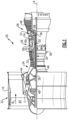
- a gas turbine engine typically includes a fan section, a compressor section, a combustor section and a turbine section. Air entering the compressor section is compressed and delivered into the combustion section where it is mixed with fuel and ignited to generate a high-speed exhaust gas flow. The high-speed exhaust gas flow expands through the turbine section to drive the compressor and the fan section.
- the compressor section typically includes low and high pressure compressors, and the turbine section includes low and high pressure turbines.
- the high pressure turbine drives the high pressure compressor through an outer shaft to form a high spool
- the low pressure turbine drives the low pressure compressor through an inner shaft to form a low spool.
- the fan section may also be driven by the low inner shaft.
- a direct drive gas turbine engine includes a fan section driven by the low spool such that the low pressure compressor, low pressure turbine and fan section rotate at a common speed in a common direction.
- EP 0031174 A1 discloses a prior art airfoil according to the preamble of claim 1.
- the core airflow is compressed by the low pressure compressor 44 then the high pressure compressor 52, mixed and burned with fuel in the combustor 56, then expanded over the high pressure turbine 54 and low pressure turbine 46.
- the mid-turbine frame 57 includes airfoils 59 which are in the core airflow path C.
- the turbines 46, 54 rotationally drive the respective low speed spool 30 and high speed spool 32 in response to the expansion.
- gear system 48 may be located aft of the low pressure compressor, or aft of the combustor section 26 or even aft of turbine section 28, and fan 42 may be positioned forward or aft of the location of gear system 48.
- the fan section 22 of the engine 20 is designed for a particular flight condition -- typically cruise at about 0.8 Mach and about 35,000 feet (10,668 meters).
- the flight condition of 0.8 Mach and 35,000 ft (10,668 meters), with the engine at its best fuel consumption - also known as "bucket cruise Thrust Specific Fuel Consumption ('TSFC')" - is the industry standard parameter of lbm of fuel being burned divided by lbf of thrust the engine produces at that minimum point.
- "Low fan pressure ratio” is the pressure ratio across the fan blade alone, without a Fan Exit Guide Vane (“FEGV”) system.
- the low fan pressure ratio as disclosed herein according to one non-limiting embodiment is less than about 1.45.
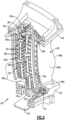
- the outer wall 68 circumscribes an internal core cavity 70.
- the airfoil section 66 may include a rib 72 that partitions the cavity 70 into a forward core cavity 70a and an aft core cavity 70b.
- the airfoil section 66 further includes a skincore passage 74 embedded in the first side 68c.
- the skincore passage 74 is a cooling passage network and may also be referred to as a skincore.
- a "skincore” or “skincore passage” is a reference to the thin investment casting core or cores that is/are typically used to make such embedded passages, as opposed to a main core that is used to form a main or central core cavity in an airfoil.
- a typical airfoil may be formed using several investment casting cores. Each core produces a passage or cavity in the airfoil. Bleed air from the compressor is typically fed to the passages and cavities for cooling the airfoil. Although effective for cooling, use of bleed air penalizes engine efficiency. Using less bleed air and using it more efficiently is desirable, however, there must be sufficient cooling to maintain durability requirements of the airfoil. A potential solution to improving bleed air efficiency is passing the bleed air through more of the airfoil. A challenge to that, however, is that it can be difficult to interconnect the various passages and cavities so that the bleed air can serially flow through more of the airfoil.
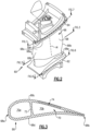
- the airfoil 60 has an interconnection of several cores to provide a cooling passage circuit 76 ("circuit 76") that winds through the first platform 62, the airfoil section 66, and the second platform 64.
- circuit 76 cooling passage circuit
- the wall may be machined to form a portion of or all of the second connector passage 84.
- the platforms 62/64 may be cast with open or partially open faces.
- covers 94 may be attached, such as by welding, over the faces. For instance, the cover 94 on the first platform 62 encloses the first connector passage 80 and a portion of the first plenum 78, and the cover 94 on the second platform 64 encloses the second connector passage 84 and a portion of the second plenum 86.
- the circuit 76 provides a winding path in the airfoil 60 for flow of the bleed air.
- the first plenum 78 wraps around a substantial portion of the trailing half of the first platform 62 and turns and extends under the airfoil section 66 to the skincore passage 82.
- the circuit 76 makes nearly a 360° loop.
- the circuit 76 provides cooling for the first side 68c of the airfoil section 66, which in the example is the suction side.
- the second connector passage 84 then turns the bleed air toward the perimeter of the second platform 64 and into the second plenum 86.
- the second plenum 86 wraps around a substantial portion of the trailing half of the second platform 64.
- the network 76 thus provides a continuous and relatively lengthy path for the bleed air flow to absorb heat from the airfoil and thereby enhance bleed air use for cooling.
Landscapes
- Engineering & Computer Science (AREA)
- Mechanical Engineering (AREA)
- General Engineering & Computer Science (AREA)
- Chemical & Material Sciences (AREA)
- Combustion & Propulsion (AREA)
- Physics & Mathematics (AREA)
- Fluid Mechanics (AREA)
- Turbine Rotor Nozzle Sealing (AREA)
- Structures Of Non-Positive Displacement Pumps (AREA)
Claims (10)
- Schaufel (60), umfassend:einen Schaufelabschnitt (66), der eine Schaufelwand (68) aufweist, die ein vorderes Ende (68a), ein hinteres Ende (68b) und eine erste und eine zweite Seite (68c, 68d) definiert, die das vordere Ende (68a) und das hintere Ende (68b) verbinden, wobei sich die erste und die zweite Seite (68c, 68d) in einer Längsrichtung (A1) zwischen einem ersten und einem zweiten Ende (68e, 68f) erstrecken, wobei die Schaufelwand (68) einen inneren Kernhohlraum (70) umschreibt;eine erste und eine zweite Plattform (62, 64), die jeweils an dem ersten und dem zweiten Ende (68e, 68f) angebracht sind;einen Kühlkreis (76), der sich in der ersten Plattform (62), dem Schaufelabschnitt (66) und der zweiten Plattform (64) erstreckt, wobei der Kühlkreis (76) Folgendes beinhaltet:ein erstes Plenum (78) in der ersten Plattform (62), wobei sich das erste Plenum (78) benachbart zu der ersten Seite (68c) der Schaufelwand (68), benachbart zu dem hinteren Ende (68b) und benachbart zu der zweiten Seite (68d) der Schaufelwand (68) erstreckt,einen Hautkernkanal (82), der in der ersten Seite (68c) der Schaufelwand (68) eingebettet ist und sich in Längsrichtung erstreckt,einen ersten Verbindungskanal (80), der in Längsrichtung von dem inneren Kernhohlraum (70) so beabstandet ist, dass er sich um den inneren Kernhohlraum (70) herum erstreckt, wobei der erste Verbindungskanal (80) das erste Plenum (78) mit dem Hautkernkanal (82) verbindet,ein zweites Plenum (86) in der zweiten Plattform (64), wobei sich das zweite Plenum (86) benachbart zu der ersten Seite (68c) der Schaufelwand (68), benachbart zu dem hinteren Ende (68b) und benachbart zu der zweiten Seite (68d) der Schaufelwand (68) erstreckt, undeinen zweiten Verbindungskanal (84), der den Hautkernkanal (82) mit dem zweiten Plenum (86) verbindet;dadurch gekennzeichnet, dass:das erste Plenum (78) einen Teil der hinteren Hälfte der ersten Plattform (62) umschlingt und sich der erste Verbindungskanal (80) dreht und sich unter dem Schaufelabschnitt (66) zu dem Hautkernkanal (82) erstreckt und das zweite Plenum (86) einen Teil der hinteren Hälfte der zweiten Plattform (64) umschlingt.
- Schaufel nach Anspruch 1, wobei das erste Plenum (78) einen Einlass (78a) benachbart zu der ersten Seite (68c) aufweist.
- Schaufel nach Anspruch 1 oder 2, wobei das erste Plenum (78) den inneren Kernhohlraum (70) umschlingt.
- Schaufel nach Anspruch 1, 2 oder 3, wobei der Hautkernkanal (82) eine Vielzahl von in Längsrichtung langgestreckten Rippen (88) beinhaltet, die zwischen sich in Längsrichtung langgestreckte Kanäle (90) definieren.
- Schaufel nach Anspruch 4, wobei der Kernhautkanal (82) eine Vielzahl von Verwirbelungsleisten (90a) in den in Längsrichtung langgestreckten Kanälen (90) beinhaltet.
- Schaufel nach einem der vorhergehenden Ansprüche, wobei der zweite Verbindungskanal (84) eine zentrale Verbindungskanalachse (84a) definiert, die mit der Längsrichtung (A1) einen schrägen Winkel (84b) bildet.
- Schaufel nach einem der vorhergehenden Ansprüche, wobei das zweite Plenum (86) eine Vielzahl von Verwirbelungsleisten (86a) beinhaltet.
- Schaufel nach einem der vorhergehenden Ansprüche, wobei die zweite Plattform (64) eine Vielzahl von Öffnungen (92) beinhaltet, wobei jede Öffnung (92) ein Einlassende (92a), das sich zu dem zweiten Plenum (86) hin öffnet, und ein Auslassende (92b), das sich zu einer Außenseite der zweiten Plattform (64) hin öffnet, aufweist.
- Schaufel nach einem der vorhergehenden Ansprüche, wobei die erste Seite (68c) eine Saugseite ist und die zweite Seite (68d) eine Druckseite ist.
- Gasturbinentriebwerk (20), umfassend:einen Verdichterabschnitt (24);eine Brennkammer (56) in Fluidverbindung mit dem Verdichterabschnitt (24); undeinen Turbinenabschnitt (28) in Fluidverbindung mit der Brennkammer (56),wobei der Turbinenabschnitt (28) eine Schaufel (60) gemäß der Schaufel nach einem der vorhergehenden Ansprüche aufweist.
Applications Claiming Priority (2)
| Application Number | Priority Date | Filing Date | Title |
|---|---|---|---|
| US201862757930P | 2018-11-09 | 2018-11-09 | |
| US16/594,125 US11028700B2 (en) | 2018-11-09 | 2019-10-07 | Airfoil with cooling passage circuit through platforms and airfoil section |
Publications (2)
| Publication Number | Publication Date |
|---|---|
| EP3650641A1 EP3650641A1 (de) | 2020-05-13 |
| EP3650641B1 true EP3650641B1 (de) | 2024-07-10 |
Family
ID=68501422
Family Applications (1)
| Application Number | Title | Priority Date | Filing Date |
|---|---|---|---|
| EP19207980.4A Active EP3650641B1 (de) | 2018-11-09 | 2019-11-08 | Schaufel mit kühlkreis durch plattformen und schaufelabschnitte |
Country Status (2)
| Country | Link |
|---|---|
| US (1) | US11028700B2 (de) |
| EP (1) | EP3650641B1 (de) |
Families Citing this family (1)
| Publication number | Priority date | Publication date | Assignee | Title |
|---|---|---|---|---|
| US12098654B2 (en) | 2021-12-21 | 2024-09-24 | Rolls-Royce Corporation | Bi-cast trailing edge feed and purge hole cooling scheme |
Citations (1)
| Publication number | Priority date | Publication date | Assignee | Title |
|---|---|---|---|---|
| EP0031174B1 (de) * | 1979-12-20 | 1984-08-22 | BBC Aktiengesellschaft Brown, Boveri & Cie. | Gekühlte Gasturbinenschaufel |
Family Cites Families (8)
| Publication number | Priority date | Publication date | Assignee | Title |
|---|---|---|---|---|
| BE794195A (fr) | 1972-01-18 | 1973-07-18 | Bbc Sulzer Turbomaschinen | Aube directrice refroidie pour des turbines a gaz |
| US7553131B2 (en) * | 2006-07-21 | 2009-06-30 | United Technologies Corporation | Integrated platform, tip, and main body microcircuits for turbine blades |
| US7819629B2 (en) * | 2007-02-15 | 2010-10-26 | Siemens Energy, Inc. | Blade for a gas turbine |
| US7967568B2 (en) | 2007-09-21 | 2011-06-28 | Siemens Energy, Inc. | Gas turbine component with reduced cooling air requirement |
| US8414263B1 (en) | 2012-03-22 | 2013-04-09 | Florida Turbine Technologies, Inc. | Turbine stator vane with near wall integrated micro cooling channels |
| US9021816B2 (en) * | 2012-07-02 | 2015-05-05 | United Technologies Corporation | Gas turbine engine turbine vane platform core |
| CA2954785A1 (en) | 2016-01-25 | 2017-07-25 | Rolls-Royce Corporation | Forward flowing serpentine vane |
| US10472974B2 (en) * | 2017-02-14 | 2019-11-12 | General Electric Company | Turbomachine rotor blade |
-
2019
- 2019-10-07 US US16/594,125 patent/US11028700B2/en active Active
- 2019-11-08 EP EP19207980.4A patent/EP3650641B1/de active Active
Patent Citations (1)
| Publication number | Priority date | Publication date | Assignee | Title |
|---|---|---|---|---|
| EP0031174B1 (de) * | 1979-12-20 | 1984-08-22 | BBC Aktiengesellschaft Brown, Boveri & Cie. | Gekühlte Gasturbinenschaufel |
Also Published As
| Publication number | Publication date |
|---|---|
| US20200332661A1 (en) | 2020-10-22 |
| US11028700B2 (en) | 2021-06-08 |
| EP3650641A1 (de) | 2020-05-13 |
Similar Documents
| Publication | Publication Date | Title |
|---|---|---|
| EP3480430B1 (de) | Integral beschaufelter rotor für ein gasturbinentriebwerk und verfahren zur herstellung eines integral beschaufelten rotors für ein gasturbinentriebwerk | |
| EP3090126B1 (de) | Bauteil eines gasturbinentriebwerks mit endwandkonturgraben | |
| EP3091186B1 (de) | Turbinenmotorkomponente mit einem durch einen absatz unterbrochenen axial ausgerichteten verkleidungskernkanal | |
| US11970954B2 (en) | Airfoil with rib having connector arms | |
| EP3670836B1 (de) | Schaufelplattform mit kühlöffnungen | |
| EP3034793B1 (de) | Gasturbinenmotorkomponente mit erhöhter kühlleistung | |
| EP3094823B1 (de) | Bauteil eines gasturbinentriebwerks und zugehöriges gasturbinentriebwerk | |
| EP3650655B1 (de) | Schaufelprofil, zugehöriges gasturbinentriebwerk und montageverfahren | |
| US20180252108A1 (en) | Staggered core printout | |
| US20160376989A1 (en) | Core assembly for gas turbine engine | |
| EP3650644B1 (de) | Schaufel mit benachbart angeordnetem kühlkanalnetz mit hohlraum | |
| EP3650641B1 (de) | Schaufel mit kühlkreis durch plattformen und schaufelabschnitte | |
| EP3650646B1 (de) | Schaufel mit prallbrause und kühlkanalnetz mit hinterem einlass | |
| EP3650642B1 (de) | Schaufel mit kühlkanalabschnitt mit gebogener vorderkante | |
| EP3670841B1 (de) | Schaufel mit hybrider haut-kern-passagennachversorgung | |
| EP3556997B1 (de) | Schaufel mit einlassöffnung an der hinteren seite der wurzel | |
| EP3650654B1 (de) | Schaufelprofil, zugehöriges gasturbinentriebwerk und montageverfahren | |
| EP3584409B1 (de) | Turbinenschaufel mit minikernkanal mit geneigter diffusoröffnung | |
| EP3650651B1 (de) | Schaufel mit einer sich in ihrer dicke verjüngenden wand | |
| EP2942486B1 (de) | Konfiguration des kühlkanals einer gasturbinenmotorschaufel | |
| EP3581762B1 (de) | Kühlkanalanordnung für gasturbinendeckband | |
| EP3650643A1 (de) | Schaufelblatt mit kernhohlraum, der sich in den plattformboden hinein erstreckt |
Legal Events
| Date | Code | Title | Description |
|---|---|---|---|
| PUAI | Public reference made under article 153(3) epc to a published international application that has entered the european phase |
Free format text: ORIGINAL CODE: 0009012 |
|
| STAA | Information on the status of an ep patent application or granted ep patent |
Free format text: STATUS: THE APPLICATION HAS BEEN PUBLISHED |
|
| AK | Designated contracting states |
Kind code of ref document: A1 Designated state(s): AL AT BE BG CH CY CZ DE DK EE ES FI FR GB GR HR HU IE IS IT LI LT LU LV MC MK MT NL NO PL PT RO RS SE SI SK SM TR |
|
| AX | Request for extension of the european patent |
Extension state: BA ME |
|
| STAA | Information on the status of an ep patent application or granted ep patent |
Free format text: STATUS: REQUEST FOR EXAMINATION WAS MADE |
|
| 17P | Request for examination filed |
Effective date: 20201112 |
|
| RBV | Designated contracting states (corrected) |
Designated state(s): AL AT BE BG CH CY CZ DE DK EE ES FI FR GB GR HR HU IE IS IT LI LT LU LV MC MK MT NL NO PL PT RO RS SE SI SK SM TR |
|
| RAP1 | Party data changed (applicant data changed or rights of an application transferred) |
Owner name: RAYTHEON TECHNOLOGIES CORPORATION |
|
| STAA | Information on the status of an ep patent application or granted ep patent |
Free format text: STATUS: EXAMINATION IS IN PROGRESS |
|
| 17Q | First examination report despatched |
Effective date: 20210901 |
|
| RAP3 | Party data changed (applicant data changed or rights of an application transferred) |
Owner name: RTX CORPORATION |
|
| GRAP | Despatch of communication of intention to grant a patent |
Free format text: ORIGINAL CODE: EPIDOSNIGR1 |
|
| STAA | Information on the status of an ep patent application or granted ep patent |
Free format text: STATUS: GRANT OF PATENT IS INTENDED |
|
| INTG | Intention to grant announced |
Effective date: 20240201 |
|
| GRAS | Grant fee paid |
Free format text: ORIGINAL CODE: EPIDOSNIGR3 |
|
| GRAA | (expected) grant |
Free format text: ORIGINAL CODE: 0009210 |
|
| STAA | Information on the status of an ep patent application or granted ep patent |
Free format text: STATUS: THE PATENT HAS BEEN GRANTED |
|
| AK | Designated contracting states |
Kind code of ref document: B1 Designated state(s): AL AT BE BG CH CY CZ DE DK EE ES FI FR GB GR HR HU IE IS IT LI LT LU LV MC MK MT NL NO PL PT RO RS SE SI SK SM TR |
|
| REG | Reference to a national code |
Ref country code: CH Ref legal event code: EP |
|
| REG | Reference to a national code |
Ref country code: DE Ref legal event code: R096 Ref document number: 602019054904 Country of ref document: DE |
|
| REG | Reference to a national code |
Ref country code: LT Ref legal event code: MG9D |
|
| REG | Reference to a national code |
Ref country code: NL Ref legal event code: MP Effective date: 20240710 |
|
| PG25 | Lapsed in a contracting state [announced via postgrant information from national office to epo] |
Ref country code: PT Free format text: LAPSE BECAUSE OF FAILURE TO SUBMIT A TRANSLATION OF THE DESCRIPTION OR TO PAY THE FEE WITHIN THE PRESCRIBED TIME-LIMIT Effective date: 20241111 |
|
| REG | Reference to a national code |
Ref country code: AT Ref legal event code: MK05 Ref document number: 1702189 Country of ref document: AT Kind code of ref document: T Effective date: 20240710 |
|
| PG25 | Lapsed in a contracting state [announced via postgrant information from national office to epo] |
Ref country code: NL Free format text: LAPSE BECAUSE OF FAILURE TO SUBMIT A TRANSLATION OF THE DESCRIPTION OR TO PAY THE FEE WITHIN THE PRESCRIBED TIME-LIMIT Effective date: 20240710 |
|
| PG25 | Lapsed in a contracting state [announced via postgrant information from national office to epo] |
Ref country code: PT Free format text: LAPSE BECAUSE OF FAILURE TO SUBMIT A TRANSLATION OF THE DESCRIPTION OR TO PAY THE FEE WITHIN THE PRESCRIBED TIME-LIMIT Effective date: 20241111 Ref country code: NL Free format text: LAPSE BECAUSE OF FAILURE TO SUBMIT A TRANSLATION OF THE DESCRIPTION OR TO PAY THE FEE WITHIN THE PRESCRIBED TIME-LIMIT Effective date: 20240710 |
|
| PGFP | Annual fee paid to national office [announced via postgrant information from national office to epo] |
Ref country code: DE Payment date: 20241022 Year of fee payment: 6 |
|
| PG25 | Lapsed in a contracting state [announced via postgrant information from national office to epo] |
Ref country code: NO Free format text: LAPSE BECAUSE OF FAILURE TO SUBMIT A TRANSLATION OF THE DESCRIPTION OR TO PAY THE FEE WITHIN THE PRESCRIBED TIME-LIMIT Effective date: 20241010 |
|
| PG25 | Lapsed in a contracting state [announced via postgrant information from national office to epo] |
Ref country code: GR Free format text: LAPSE BECAUSE OF FAILURE TO SUBMIT A TRANSLATION OF THE DESCRIPTION OR TO PAY THE FEE WITHIN THE PRESCRIBED TIME-LIMIT Effective date: 20241011 Ref country code: FI Free format text: LAPSE BECAUSE OF FAILURE TO SUBMIT A TRANSLATION OF THE DESCRIPTION OR TO PAY THE FEE WITHIN THE PRESCRIBED TIME-LIMIT Effective date: 20240710 Ref country code: PL Free format text: LAPSE BECAUSE OF FAILURE TO SUBMIT A TRANSLATION OF THE DESCRIPTION OR TO PAY THE FEE WITHIN THE PRESCRIBED TIME-LIMIT Effective date: 20240710 |
|
| PGFP | Annual fee paid to national office [announced via postgrant information from national office to epo] |
Ref country code: GB Payment date: 20241022 Year of fee payment: 6 |
|
| PG25 | Lapsed in a contracting state [announced via postgrant information from national office to epo] |
Ref country code: BG Free format text: LAPSE BECAUSE OF FAILURE TO SUBMIT A TRANSLATION OF THE DESCRIPTION OR TO PAY THE FEE WITHIN THE PRESCRIBED TIME-LIMIT Effective date: 20240710 |
|
| PG25 | Lapsed in a contracting state [announced via postgrant information from national office to epo] |
Ref country code: LV Free format text: LAPSE BECAUSE OF FAILURE TO SUBMIT A TRANSLATION OF THE DESCRIPTION OR TO PAY THE FEE WITHIN THE PRESCRIBED TIME-LIMIT Effective date: 20240710 |
|
| PG25 | Lapsed in a contracting state [announced via postgrant information from national office to epo] |
Ref country code: AT Free format text: LAPSE BECAUSE OF FAILURE TO SUBMIT A TRANSLATION OF THE DESCRIPTION OR TO PAY THE FEE WITHIN THE PRESCRIBED TIME-LIMIT Effective date: 20240710 Ref country code: IS Free format text: LAPSE BECAUSE OF FAILURE TO SUBMIT A TRANSLATION OF THE DESCRIPTION OR TO PAY THE FEE WITHIN THE PRESCRIBED TIME-LIMIT Effective date: 20241110 |
|
| PGFP | Annual fee paid to national office [announced via postgrant information from national office to epo] |
Ref country code: FR Payment date: 20241022 Year of fee payment: 6 |
|
| PG25 | Lapsed in a contracting state [announced via postgrant information from national office to epo] |
Ref country code: HR Free format text: LAPSE BECAUSE OF FAILURE TO SUBMIT A TRANSLATION OF THE DESCRIPTION OR TO PAY THE FEE WITHIN THE PRESCRIBED TIME-LIMIT Effective date: 20240710 |
|
| PG25 | Lapsed in a contracting state [announced via postgrant information from national office to epo] |
Ref country code: RS Free format text: LAPSE BECAUSE OF FAILURE TO SUBMIT A TRANSLATION OF THE DESCRIPTION OR TO PAY THE FEE WITHIN THE PRESCRIBED TIME-LIMIT Effective date: 20241010 Ref country code: ES Free format text: LAPSE BECAUSE OF FAILURE TO SUBMIT A TRANSLATION OF THE DESCRIPTION OR TO PAY THE FEE WITHIN THE PRESCRIBED TIME-LIMIT Effective date: 20240710 |
|
| PG25 | Lapsed in a contracting state [announced via postgrant information from national office to epo] |
Ref country code: RS Free format text: LAPSE BECAUSE OF FAILURE TO SUBMIT A TRANSLATION OF THE DESCRIPTION OR TO PAY THE FEE WITHIN THE PRESCRIBED TIME-LIMIT Effective date: 20241010 Ref country code: PL Free format text: LAPSE BECAUSE OF FAILURE TO SUBMIT A TRANSLATION OF THE DESCRIPTION OR TO PAY THE FEE WITHIN THE PRESCRIBED TIME-LIMIT Effective date: 20240710 Ref country code: NO Free format text: LAPSE BECAUSE OF FAILURE TO SUBMIT A TRANSLATION OF THE DESCRIPTION OR TO PAY THE FEE WITHIN THE PRESCRIBED TIME-LIMIT Effective date: 20241010 Ref country code: LV Free format text: LAPSE BECAUSE OF FAILURE TO SUBMIT A TRANSLATION OF THE DESCRIPTION OR TO PAY THE FEE WITHIN THE PRESCRIBED TIME-LIMIT Effective date: 20240710 Ref country code: IS Free format text: LAPSE BECAUSE OF FAILURE TO SUBMIT A TRANSLATION OF THE DESCRIPTION OR TO PAY THE FEE WITHIN THE PRESCRIBED TIME-LIMIT Effective date: 20241110 Ref country code: HR Free format text: LAPSE BECAUSE OF FAILURE TO SUBMIT A TRANSLATION OF THE DESCRIPTION OR TO PAY THE FEE WITHIN THE PRESCRIBED TIME-LIMIT Effective date: 20240710 Ref country code: GR Free format text: LAPSE BECAUSE OF FAILURE TO SUBMIT A TRANSLATION OF THE DESCRIPTION OR TO PAY THE FEE WITHIN THE PRESCRIBED TIME-LIMIT Effective date: 20241011 Ref country code: FI Free format text: LAPSE BECAUSE OF FAILURE TO SUBMIT A TRANSLATION OF THE DESCRIPTION OR TO PAY THE FEE WITHIN THE PRESCRIBED TIME-LIMIT Effective date: 20240710 Ref country code: ES Free format text: LAPSE BECAUSE OF FAILURE TO SUBMIT A TRANSLATION OF THE DESCRIPTION OR TO PAY THE FEE WITHIN THE PRESCRIBED TIME-LIMIT Effective date: 20240710 Ref country code: BG Free format text: LAPSE BECAUSE OF FAILURE TO SUBMIT A TRANSLATION OF THE DESCRIPTION OR TO PAY THE FEE WITHIN THE PRESCRIBED TIME-LIMIT Effective date: 20240710 Ref country code: AT Free format text: LAPSE BECAUSE OF FAILURE TO SUBMIT A TRANSLATION OF THE DESCRIPTION OR TO PAY THE FEE WITHIN THE PRESCRIBED TIME-LIMIT Effective date: 20240710 |
|
| REG | Reference to a national code |
Ref country code: DE Ref legal event code: R097 Ref document number: 602019054904 Country of ref document: DE |
|
| PG25 | Lapsed in a contracting state [announced via postgrant information from national office to epo] |
Ref country code: SM Free format text: LAPSE BECAUSE OF FAILURE TO SUBMIT A TRANSLATION OF THE DESCRIPTION OR TO PAY THE FEE WITHIN THE PRESCRIBED TIME-LIMIT Effective date: 20240710 Ref country code: RO Free format text: LAPSE BECAUSE OF FAILURE TO SUBMIT A TRANSLATION OF THE DESCRIPTION OR TO PAY THE FEE WITHIN THE PRESCRIBED TIME-LIMIT Effective date: 20240710 Ref country code: DK Free format text: LAPSE BECAUSE OF FAILURE TO SUBMIT A TRANSLATION OF THE DESCRIPTION OR TO PAY THE FEE WITHIN THE PRESCRIBED TIME-LIMIT Effective date: 20240710 |
|
| PG25 | Lapsed in a contracting state [announced via postgrant information from national office to epo] |
Ref country code: EE Free format text: LAPSE BECAUSE OF FAILURE TO SUBMIT A TRANSLATION OF THE DESCRIPTION OR TO PAY THE FEE WITHIN THE PRESCRIBED TIME-LIMIT Effective date: 20240710 |
|
| PG25 | Lapsed in a contracting state [announced via postgrant information from national office to epo] |
Ref country code: CZ Free format text: LAPSE BECAUSE OF FAILURE TO SUBMIT A TRANSLATION OF THE DESCRIPTION OR TO PAY THE FEE WITHIN THE PRESCRIBED TIME-LIMIT Effective date: 20240710 |
|
| PG25 | Lapsed in a contracting state [announced via postgrant information from national office to epo] |
Ref country code: IT Free format text: LAPSE BECAUSE OF FAILURE TO SUBMIT A TRANSLATION OF THE DESCRIPTION OR TO PAY THE FEE WITHIN THE PRESCRIBED TIME-LIMIT Effective date: 20240710 Ref country code: SK Free format text: LAPSE BECAUSE OF FAILURE TO SUBMIT A TRANSLATION OF THE DESCRIPTION OR TO PAY THE FEE WITHIN THE PRESCRIBED TIME-LIMIT Effective date: 20240710 |
|
| PLBE | No opposition filed within time limit |
Free format text: ORIGINAL CODE: 0009261 |
|
| STAA | Information on the status of an ep patent application or granted ep patent |
Free format text: STATUS: NO OPPOSITION FILED WITHIN TIME LIMIT |
|
| 26N | No opposition filed |
Effective date: 20250411 |
|
| REG | Reference to a national code |
Ref country code: CH Ref legal event code: PL |
|
| PG25 | Lapsed in a contracting state [announced via postgrant information from national office to epo] |
Ref country code: MC Free format text: LAPSE BECAUSE OF FAILURE TO SUBMIT A TRANSLATION OF THE DESCRIPTION OR TO PAY THE FEE WITHIN THE PRESCRIBED TIME-LIMIT Effective date: 20240710 |
|
| PG25 | Lapsed in a contracting state [announced via postgrant information from national office to epo] |
Ref country code: LU Free format text: LAPSE BECAUSE OF NON-PAYMENT OF DUE FEES Effective date: 20241108 |
|
| REG | Reference to a national code |
Ref country code: CH Ref legal event code: PL |
|
| PG25 | Lapsed in a contracting state [announced via postgrant information from national office to epo] |
Ref country code: CH Free format text: LAPSE BECAUSE OF NON-PAYMENT OF DUE FEES Effective date: 20241130 |
|
| REG | Reference to a national code |
Ref country code: BE Ref legal event code: MM Effective date: 20241130 |
|
| PG25 | Lapsed in a contracting state [announced via postgrant information from national office to epo] |
Ref country code: SE Free format text: LAPSE BECAUSE OF FAILURE TO SUBMIT A TRANSLATION OF THE DESCRIPTION OR TO PAY THE FEE WITHIN THE PRESCRIBED TIME-LIMIT Effective date: 20240710 |
|
| PG25 | Lapsed in a contracting state [announced via postgrant information from national office to epo] |
Ref country code: BE Free format text: LAPSE BECAUSE OF NON-PAYMENT OF DUE FEES Effective date: 20241130 |
|
| PG25 | Lapsed in a contracting state [announced via postgrant information from national office to epo] |
Ref country code: IE Free format text: LAPSE BECAUSE OF NON-PAYMENT OF DUE FEES Effective date: 20241108 |