EP3650273B1 - Tray for vehicle storage space and manufacturing method of tray for vehicle storage space - Google Patents
Tray for vehicle storage space and manufacturing method of tray for vehicle storage space Download PDFInfo
- Publication number
- EP3650273B1 EP3650273B1 EP19208111.5A EP19208111A EP3650273B1 EP 3650273 B1 EP3650273 B1 EP 3650273B1 EP 19208111 A EP19208111 A EP 19208111A EP 3650273 B1 EP3650273 B1 EP 3650273B1
- Authority
- EP
- European Patent Office
- Prior art keywords
- cuts
- tray
- storage space
- vehicle storage
- fiber board
- Prior art date
- Legal status (The legal status is an assumption and is not a legal conclusion. Google has not performed a legal analysis and makes no representation as to the accuracy of the status listed.)
- Active
Links
Images


Classifications
-
- B—PERFORMING OPERATIONS; TRANSPORTING
- B60—VEHICLES IN GENERAL
- B60R—VEHICLES, VEHICLE FITTINGS, OR VEHICLE PARTS, NOT OTHERWISE PROVIDED FOR
- B60R5/00—Compartments within vehicle body primarily intended or sufficiently spacious for trunks, suit-cases, or the like
- B60R5/04—Compartments within vehicle body primarily intended or sufficiently spacious for trunks, suit-cases, or the like arranged at rear of vehicle
-
- B—PERFORMING OPERATIONS; TRANSPORTING
- B31—MAKING ARTICLES OF PAPER, CARDBOARD OR MATERIAL WORKED IN A MANNER ANALOGOUS TO PAPER; WORKING PAPER, CARDBOARD OR MATERIAL WORKED IN A MANNER ANALOGOUS TO PAPER
- B31B—MAKING CONTAINERS OF PAPER, CARDBOARD OR MATERIAL WORKED IN A MANNER ANALOGOUS TO PAPER
- B31B50/00—Making rigid or semi-rigid containers, e.g. boxes or cartons
- B31B50/14—Cutting, e.g. perforating, punching, slitting or trimming
- B31B50/20—Cutting sheets or blanks
-
- B—PERFORMING OPERATIONS; TRANSPORTING
- B31—MAKING ARTICLES OF PAPER, CARDBOARD OR MATERIAL WORKED IN A MANNER ANALOGOUS TO PAPER; WORKING PAPER, CARDBOARD OR MATERIAL WORKED IN A MANNER ANALOGOUS TO PAPER
- B31B—MAKING CONTAINERS OF PAPER, CARDBOARD OR MATERIAL WORKED IN A MANNER ANALOGOUS TO PAPER
- B31B50/00—Making rigid or semi-rigid containers, e.g. boxes or cartons
- B31B50/25—Surface scoring
-
- B—PERFORMING OPERATIONS; TRANSPORTING
- B31—MAKING ARTICLES OF PAPER, CARDBOARD OR MATERIAL WORKED IN A MANNER ANALOGOUS TO PAPER; WORKING PAPER, CARDBOARD OR MATERIAL WORKED IN A MANNER ANALOGOUS TO PAPER
- B31B—MAKING CONTAINERS OF PAPER, CARDBOARD OR MATERIAL WORKED IN A MANNER ANALOGOUS TO PAPER
- B31B50/00—Making rigid or semi-rigid containers, e.g. boxes or cartons
- B31B50/26—Folding sheets, blanks or webs
-
- B—PERFORMING OPERATIONS; TRANSPORTING
- B31—MAKING ARTICLES OF PAPER, CARDBOARD OR MATERIAL WORKED IN A MANNER ANALOGOUS TO PAPER; WORKING PAPER, CARDBOARD OR MATERIAL WORKED IN A MANNER ANALOGOUS TO PAPER
- B31B—MAKING CONTAINERS OF PAPER, CARDBOARD OR MATERIAL WORKED IN A MANNER ANALOGOUS TO PAPER
- B31B50/00—Making rigid or semi-rigid containers, e.g. boxes or cartons
- B31B50/74—Auxiliary operations
-
- B—PERFORMING OPERATIONS; TRANSPORTING
- B31—MAKING ARTICLES OF PAPER, CARDBOARD OR MATERIAL WORKED IN A MANNER ANALOGOUS TO PAPER; WORKING PAPER, CARDBOARD OR MATERIAL WORKED IN A MANNER ANALOGOUS TO PAPER
- B31D—MAKING ARTICLES OF PAPER, CARDBOARD OR MATERIAL WORKED IN A MANNER ANALOGOUS TO PAPER, NOT PROVIDED FOR IN SUBCLASSES B31B OR B31C
- B31D5/00—Multiple-step processes for making three-dimensional [3D] articles
- B31D5/04—Multiple-step processes for making three-dimensional [3D] articles including folding or pleating, e.g. Chinese lanterns
-
- B—PERFORMING OPERATIONS; TRANSPORTING
- B60—VEHICLES IN GENERAL
- B60R—VEHICLES, VEHICLE FITTINGS, OR VEHICLE PARTS, NOT OTHERWISE PROVIDED FOR
- B60R7/00—Stowing or holding appliances inside vehicle primarily intended for personal property smaller than suit-cases, e.g. travelling articles, or maps
- B60R7/02—Stowing or holding appliances inside vehicle primarily intended for personal property smaller than suit-cases, e.g. travelling articles, or maps in separate luggage compartment
-
- B—PERFORMING OPERATIONS; TRANSPORTING
- B65—CONVEYING; PACKING; STORING; HANDLING THIN OR FILAMENTARY MATERIAL
- B65D—CONTAINERS FOR STORAGE OR TRANSPORT OF ARTICLES OR MATERIALS, e.g. BAGS, BARRELS, BOTTLES, BOXES, CANS, CARTONS, CRATES, DRUMS, JARS, TANKS, HOPPERS, FORWARDING CONTAINERS; ACCESSORIES, CLOSURES, OR FITTINGS THEREFOR; PACKAGING ELEMENTS; PACKAGES
- B65D5/00—Rigid or semi-rigid containers of polygonal cross-section, e.g. boxes, cartons or trays, formed by folding or erecting one or more blanks made of paper
- B65D5/20—Rigid or semi-rigid containers of polygonal cross-section, e.g. boxes, cartons or trays, formed by folding or erecting one or more blanks made of paper by folding-up portions connected to a central panel from all sides to form a container body, e.g. of tray-like form
- B65D5/2014—Rigid or semi-rigid containers of polygonal cross-section, e.g. boxes, cartons or trays, formed by folding or erecting one or more blanks made of paper by folding-up portions connected to a central panel from all sides to form a container body, e.g. of tray-like form the central panel having a non rectangular shape
Definitions
- the present disclosure relates to a tray for vehicle storage space provided in, for example, behind sheets of of a vehicle, such as a motor vehicle.
- JP 2016-88318A provides a luggage space structure of a vehicle that prevents a luggage box made of a resin from being turned over forward without using a clamping member or the like and that improves the assembly of the luggage box to a luggage space.
- the luggage box described in JP 2016-88318A is made of a resin.
- the resin especially polystyrene foam, is bulky. Accordingly, this decreases the capacity of storage provided in the assembled vehicle. Problems are the difficulty in expanding the capacity of storage space and the low efficiency of component transportation.
- the inventors of the present disclosure have intensively examined the structure of the luggage board and have found the material and the configuration of the tray for vehicle storage space that overcome the problems described above.
- US2017/0081072A1 describes a base blank with foldable creases that is adapted to be erected into a carton comprising a base panel, two pairs of side panels, and corner gussets.
- a carton fabricated from a two-dimensional flat sheet material with an outer profile and an array of cuts, creases and folds is described.
- the rigidity and the total weight affects the capacity of storage, these parameters are not described in the both documents.
- a first aspect of the present disclosure provides a tray for vehicle storage space that comprises a fiber board including a bottom portion, side portions, characterized in that the fiber board further includes flat portions extended from the side portions and has a thickness of 2 to 6 mm, a total weight of 450 to 1000 g/m 2 and a tensile strength of 850 to 2150 N/ 25.4 mm; the tray for vehicle storage space further comprises linear first cuts provided in the fiber board to divide boundaries between the flat portions and the side portions; linear second cuts provided to divide boundaries between the bottom portion and the side portions; and linear third cuts provided to fold back the side portions, the tray for vehicle storage space is folded back by using the first cuts, the second cuts and the third cuts to be placed in a vehicle storage space.
- a method of measuring the tensile strength fixes respective ends in a longitudinal direction of a test piece having a length of 200 mm and a width of 50 mm in a tension testing machine and pulls the test piece at a tension rate of 200 mm/min.
- a maximum load required for fracture is defined as the tensile strength.
- the fiber board of high rigidity for example, the fiber board having a slightly higher hardness than an ordinary hardness expands the capacity of storage.
- the absolute capacity of the space of the luggage room is naturally unchanged.
- the fiber board however, has a smaller thickness than the thickness of polystyrene foam. This increases the capacity of the space that allows the user to use.
- Respective trays are set in an expanded state and are stacked one upon another during transportation. This increases the efficiency of component transportation.
- the cuts are formed in the fiber board by a predetermined depth, for example, by a cutting amount of 50 to 70% of the thickness of the fiber board, for example, half the thickness of the fiber board.
- the fiber board is then folded down along the cutting lines to be formed in a shape along the walls of the luggage room.
- the first cuts, the second cuts and the third cuts may have a width of 0.2 to 1.0 mm (i.e., the range of the thickness of a cutter).
- a second aspect of the present disclosure provides a manufacturing method of a tray for vehicle storage space, comprising a fiber board cutting process of cutting an outer circumference of a fiber board; and a cutting process of providing linear cuts, characterized in that the fiber board has a total weight of 450 to 1000 g/m 2 and a tensile strength of 850 to 2150 N/ 25.4 mm to have a bottom portion, flat portions and side portions; and the cutting process of providing linear cuts provides linear first cuts such as to divide boundaries between the flat portions and the side portions, linear second cuts such as to divide boundaries between the bottom portion and the side portions, and linear third cuts such as to fold back the side portions.
- the manufacturing method may further comprises an assembling process of folding down the first cuts and the second cuts and folding back the third cuts to assemble the fiber board in a box-like shape after the cutting process.
- the material of the fiber board is a fiber material including a first thermoplastic resin fiber and a second thermoplastic resin fiber.
- the material of the fiber board may, however, be another material, such as a natural fiber material, a glass fiber material or a material obtained by combining a natural fiber with a thermoplastic resin.
- the fiber board may have any of various shapes, such as a rectangular shape or a round shape.
- the tray for vehicle storage space can be manufactured by simply folding down and assembling the fiber board without bonding.
- the tray for vehicle storage space in the folded down and assembled state can be mounted on the vehicle.
- the tray for vehicle storage space is placed along walls of a rear storage space of a motor vehicle and is pressed down to be fastened by another component placed on the flat portions.
- the natural fiber is preferably a plant fiber (for example, kenaf fiber)
- the first thermoplastic resin fiber is preferably a polyester-based resin fiber
- the second thermoplastic resin fiber is preferably a polypropylene-based resin fiber.
- the thermoplastic resin is preferably a low melting point polyester-based resin, a low melting point polyethylene-based resin or a low melting point polypropylene-based resin.
- a plurality of, for example, three third cuts may be provided at each set of folding positions.
- the leftward or rightward folding direction may be set by controlling which of the three cuts is formed from the surface side and which of the three cuts is formed from the rear face side. This configuration improves the workability.
- the crease for folding down may be provided in a desired direction by distribution of the third cuts on the surface side and on the rear face side.
- the tray for vehicle storage space can be placed in a vehicle storage space by simply folding down and assembling the fiber board. This configuration expands the capacity of storage of the tray for vehicle storage space and increases the efficiency of component transportation.
- a tray for vehicle storage space 1 (hereinafter simply referred to as tray 1) of Embodiment 1 according to the first aspect of the present disclosure is described with reference to Figs. 1 to 3 .
- the tray 1 is formed from a fiber board 5 that includes a bottom portion 2, side portions 3 (side pieces 31 to 36) and flat portions 4 (42 to 46) extended from the side portions 3 (from the side pieces 32 to 36) and that has a thickness of 2 to 6 mm, a total weight of 450 to 1000 g/m 2 , and a tensile strength of 850 to 2150 N/ 25.4 mm.
- Fig. 1 A tray for vehicle storage space 1 (hereinafter simply referred to as tray 1) of Embodiment 1 according to the first aspect of the present disclosure is described with reference to Figs. 1 to 3 .
- the tray 1 is formed from a fiber board 5 that includes a bottom portion 2, side portions 3 (side pieces 31 to 36) and flat portions 4 (42 to 46) extended from the side portions 3 (from the side pieces
- solid lines other than solid lines indicating an outer circumference indicate foldable locations of the bottom portion 2, the side portions 3 and the flat portions 4.
- two-dot chain lines indicate boundaries between the bottom portion 2 and the side portions 3 (31 to 36) and between the side portions 3 and the flat portions 4 (42 to 46).
- the tray 1 is formed from one board and is configured, such that the six side portions 3 are respectively connected with six sides of the bottom portion 2 and that the five flat portions 4 are respectively connected with five sides corresponding to the side pieces 32 to 36 out of the six sides of the side portions 3.
- the tray 1 is transformable between an expanded state and an assembled state.
- the tray 1 is formed by simply folding down and assembling the single fiber board 5 without bonding.
- the tray 1 in the folded down and assembled state may be mounted on the vehicle.
- the tray 1 is placed along walls of a rear storage space 11 of a motor vehicle 10, and respective ends of the flat portions 42 to 46 are vertically held and fixed by a front fixing portion 20, side fixing portions 30 and a rear fixing portion 40.
- An upper opening of the tray 1 may be opened and closed by a cover 50.
- the material of the tray 1 is made of a thermoplastic resin fiber.
- the thermoplastic resin fiber is preferably a polyester-based resin fiber, a low melting point polyester-based resin fiber, a low melting point polyethylene-based fiber or a low melting point polypropylene resin fiber.
- the tray 1 is a plate like member that includes a polyester fiber and a low melting point polyester fiber as the thermoplastic resin fiber, the total weight of 450 to 1000 g/m 2 and the thickness of 2 to 6 mm.
- the material used for the tray 1 is a polyester fiber using a low melting point polyester as a binder.
- the single board of the tray 1 in the expanded state has linear first cuts 6a to 6e (shown in Fig. 3 ) provided on a surface side to divide boundaries between the side portions 3 and the flat portions 4, linear second cuts 7a to 7f (shown in Fig. 4 ) provided on a rear face side to divide boundaries between the bottom portion 2 and the side portions 3, linear third cuts 8a, 8f, 8g, 8j, 8m and 8r (shown in Fig. 3 ) provided on the surface side to fold back the side portions 3, and linear third cuts 8b, 8c, 8d, 8e, 8h, 8i, 8k, 81, 8n, 8o, 8p and 8q provided on the rear face side.
- the tray 1 is formed in a box-like structure to be placed in the rear storage space 11 of the motor vehicle 10 by folding down the first cuts 6a to 6e and the second cuts 7a to 7f and folding back the third cuts 8a to 8r without performing any additional work such as bonding.
- the following describes the configuration of the tray 1 more in detail.
- the bottom portion 2 is formed in an inequilateral hexagonal shape.
- the side portions 3 form a ring-shaped band like structure and are placed to surround the bottom portion 2.
- the side portions 3 constitute side walls. As shown in Figs. 1 to 4 , the side portions 3 include a plurality of the side pieces 31 to 36.
- the side piece 31 is provided in a middle part of an upper side of the bottom portion 2.
- the side piece 32 is provided on a left side of the bottom portion 2.
- the side piece 33 is provided on a right side of the bottom portion 2.
- the side piece 34 is provided on a lower left corner of the bottom portion 2.
- the side piece 35 is provided on a lower right corner of the bottom portion 2.
- the side piece 36 is provided on a lower side of the bottom portion 2.
- the flat portions 4 include a rectangular first flat portion 42 that connects with a left side of the side piece 32, a rectangular second flat portion 43 that connects with a right side of the side piece 33, a pentagonal third flat portion 44 that connects with a lower side of the side piece 34, a pentagonal fourth flat portion 45 that connects with a lower side of the side piece 35, and a rectangular fifth flat portion 46 that connects with a lower side of the side piece 36.
- the first cut 6a, the first cut 6b, the first cut 6c, the first cut 6d and the first cut 6e are configured to respectively separate the flat portion 42, the flat portion 43, the flat portion 44, the flat portion 45 and the flat portion 46 from the side pieces 32 to 36.
- the second cut 7a, the second cut 7b, the second cut 7c, the second cut 7d, the second cut 7e, and the second cut 7f are configured to respectively separate the side piece 31, the side piece 33, the side piece 32, the side piece 35, the side piece 34 and the side piece 36 from the bottom portion 2.
- the second cuts 7a to 7f are arranged in a hexagonal ring shape.
- the second cuts 7d and 7e are arranged to be bilaterally symmetrical.
- the third cuts 8a to 8c, the third cuts 8d to 8f, the third cuts 8g to 8i, the third cuts 8j to 81, the third cuts 8m to 8o and the third cuts 8p to 8r are respectively arranged in threes to be in triangular shapes and form parts for folding back the side portions 3.
- the left side and the right side are inverted, so that the reference signs indicating each set of three should also be inverted to be in combination.
- the third cut 8a is extended to be slanted inward from an intersection between an upper side 81 and the first cut 6a.
- the third cut 8f is extended to be slanted inward from an intersection between an upper side 82 and the first cut 6b.
- the third cut 8g is extended to be slanted inward from an intersection between an upper side 83 and the first cut 6a.
- the third cut 8j is extended to be slanted inward from an intersection between an upper side 84 and the first cut 6b.
- the third cut 8m is extended to be slanted inward from an upper side 85 and the first cut 6c.
- the third cut 8r is extended to be slanted inward from an intersection between an upper side 86 and the first cut 6d.
- the third cuts 8d and 8e are extended from an intersection between the second cuts 7a and 7b.
- the third cuts 8b and 8c are extended from an intersection between the second cuts 7a and 7c.
- the third cuts 8k and 81 are extended from an intersection between the second cuts 7b and 7d.
- the third cuts 8h and 8i are extended from an intersection between the second cuts 7c and 7e.
- the third cuts 8p and 8q are extended from an intersection between the second cuts 7d and 7f.
- the third cuts 8n and 8o are extended from an intersection between the second cuts 7f and 7e.
- the respective upper sides 81 to 86 of the triangles described above are formed in the respective sets of three.
- the upper sides 81 and 82 are straight lines.
- the upper sides 83 to 86 are folded lines that are convex downward.
- one third cut is provided on one face (surface side), and the other two third cuts are provided on the other face (rear side).
- the third cuts 8a to 8r are deformed in respective directions of opening up the respective cuts.
- the depths of the first cuts 6, the second cuts 7 and the third cuts 8 are 50 to 70% of the thickness of the fiber board 5.
- the widths of the first cuts 6, the second cuts 7 and the third cuts 8 are 0.2 to 1.0 mm (i.e., the thickness of a cutter).
- the following describes a manufacturing method of the tray for vehicle storage space of the embodiment according to the second aspect of the present disclosure.
- the manufacturing method manufactures the fiber board 5 having a total weight of 450 to 1000 g/m 2 and a tensile strength of 850 to 2150 N/ 25.4 mm and subsequently performs a fiber board cutting process of cutting the outer circumference of the fiber board 5 to form the side pieces 31 to 36, the flat portions 42 to 46, and the upper sides 81 to 86.
- the fiber board 5 has the total weight and the tensile strength that are lower than the respective lower limits, there is a difficulty in retaining the shape of the tray in the assembled state.
- the fiber board 5 has the total weight and the tensile strength that are higher than the respective upper limits, on the other hand, there is a difficulty in assembling the fiber board 5 due to the excessive hardness of the fiber board 5.
- the manufacturing method subsequently performs a cutting process of providing the linear first cuts 6a to 6e such as to divide the boundaries between the flat portions 42 to 46 and the side pieces 32 to 36, the linear second cuts 7a to 7f such as to divide the boundaries between the bottom portion 2 and the side pieces 31 to 36, and the linear third cuts 8a to 8r such as to fold down the side pieces 31 to 36.
- the manufacturing method performs an assembling process of folding down the first cuts 6a to 6e and the second cuts 7a to 7f and pinching and folding back the respective triangles surrounded by the third cuts 8a to 8r and the upper sides 81 to 86 to assemble the fiber board 5 in a box-like shape.
- the fiber board 5 has a smaller thickness than the thickness of polystyrene foam. This increases the capacity of the space that allows the user to use. Respective fiber boards are set in the expanded state and are stacked one upon another during transportation. This increases the efficiency of component transportation.
- a tool box made of polystyrene foam may be provided to place tools such as a jack therein according to a comparative example shown in Fig. 6 .
- the tray according to the embodiment of the present disclosure increases the capacity of the space, compared with such a tool box made of polystyrene foam.
- the crease for folding down may be controlled by determining which of the third cuts 8a to 8r is formed from the surface side or formed from the rear face side.
- Example 1 for the purpose of illustrating the aspects of the present disclosure more specifically.
- the present disclosure is, however, not limited to the description of this example.
- a tray 1 of Example 1 is described. Prior to assembly, the tray 1 was comprised of polyethylene terephthalate fiber and low melting point polyethylene terephthalate fiber and had a total weight of 800 g/m 2 , a thickness of 3 mm and dimensions of 85.5 cm as a vertical maximum length and 102 cm as a lateral maximum length.
- the tensile strength of the above tray 1 was measured by a procedure given below.
- the procedure fixed respective ends in a longitudinal direction of a test piece of the tray 1 having a length of 150 mm and a width of 100 mm in a tension testing machine.
- the area of the test piece to be fixed was 25.4 mm ⁇ 25.4 mm.
- fixation parts of the respective ends are respectively expressed as a fixation part A and a fixation part B, a distance between the fixation part A and the fixation part B was 76.2 mm.
- the procedure measured a load in tensile fracture at a tension rate of 200 mm/ min.
- the measured load of tensile strength was 1790 N/ 25.4 mm.
- tray 101 for vehicle storage space 101 (hereinafter simply referred to as tray 101) according to Embodiment 2 of the present disclosure with reference to Figs. 7 to 10 .
- This tray 101 is substantially similar to the tray 1 with some differences.
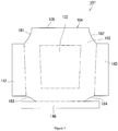
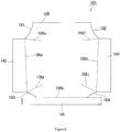
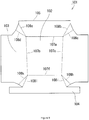
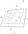
- the tray 101 of Embodiment 2 has a rectangular bottom portion 102 and includes different numbers and shapes of side portions 103 and flat portions 104.
- Like components of Embodiment 2 to the components of Embodiment 1 are expressed by like reference symbols in 100s.
- the tray for vehicle storage space according to the present disclosure is applicable for deck boards and luggage trims of vehicles, especially mini motor vehicles and small motor vehicles.
- the present disclosure is not limited to the embodiments described above but may be implemented by various other aspects in the technical scope of the present disclosure. Various modifications and variations may be made to the embodiments without departing from the technical scope of the present disclosure. Such modifications and variations, as well as their equivalents are also included in the technical scope of the present disclosure.
- the shape, the configuration, the dimensions, the material and the like of the fiber board 5 are not limited to those described in the above embodiments but may be changed or modified appropriately.
- the tray for vehicle storage space according to the present disclosure may be employed for, for example, vehicle interior components, tool boxes, and deck trays and may be applied for sedan vehicles, coupe vehicles, hatchback vehicles, and wagon vehicles as types of motor vehicles.
Landscapes
- Engineering & Computer Science (AREA)
- Mechanical Engineering (AREA)
- Cartons (AREA)
- Packaging Of Machine Parts And Wound Products (AREA)
- Vehicle Step Arrangements And Article Storage (AREA)
Description
- The present disclosure relates to a tray for vehicle storage space provided in, for example, behind sheets of of a vehicle, such as a motor vehicle.
- A proposed technique described in
JP 2016-88318A - The luggage box described in
JP 2016-88318A - The inventors of the present disclosure have intensively examined the structure of the luggage board and have found the material and the configuration of the tray for vehicle storage space that overcome the problems described above.
-
US2017/0081072A1 describes a base blank with foldable creases that is adapted to be erected into a carton comprising a base panel, two pairs of side panels, and corner gussets. InGB2303356A - A first aspect of the present disclosure provides a tray for vehicle storage space that comprises a fiber board including a bottom portion, side portions, characterized in that the fiber board further includes flat portions extended from the side portions and has a thickness of 2 to 6 mm, a total weight of 450 to 1000 g/m2 and a tensile strength of 850 to 2150 N/ 25.4 mm; the tray for vehicle storage space further comprises linear first cuts provided in the fiber board to divide boundaries between the flat portions and the side portions; linear second cuts provided to divide boundaries between the bottom portion and the side portions; and linear third cuts provided to fold back the side portions, the tray for vehicle storage space is folded back by using the first cuts, the second cuts and the third cuts to be placed in a vehicle storage space. A method of measuring the tensile strength fixes respective ends in a longitudinal direction of a test piece having a length of 200 mm and a width of 50 mm in a tension testing machine and pulls the test piece at a tension rate of 200 mm/min. A maximum load required for fracture is defined as the tensile strength. When the fiber board has the total weight and the tensile strength that are lower than the respective lower limits, there is a difficulty in retaining the shape of the tray in the assembled state. When the fiber board has the total weight and the tensile strength that are higher than the respective upper limits, on the other hand, there is a difficulty in assembling the fiber board due to the excessive hardness of the fiber board.
- Using the fiber board of high rigidity, for example, the fiber board having a slightly higher hardness than an ordinary hardness expands the capacity of storage. The absolute capacity of the space of the luggage room is naturally unchanged. The fiber board, however, has a smaller thickness than the thickness of polystyrene foam. This increases the capacity of the space that allows the user to use. Respective trays are set in an expanded state and are stacked one upon another during transportation. This increases the efficiency of component transportation.
- The cuts are formed in the fiber board by a predetermined depth, for example, by a cutting amount of 50 to 70% of the thickness of the fiber board, for example, half the thickness of the fiber board. The fiber board is then
folded down along the cutting lines to be formed in a shape along the walls of the luggage room. - The first cuts, the second cuts and the third cuts may have a width of 0.2 to 1.0 mm (i.e., the range of the thickness of a cutter).
- A second aspect of the present disclosure provides a manufacturing method of a tray for vehicle storage space, comprising a fiber board cutting process of cutting an outer circumference of a fiber board; and a cutting process of providing linear cuts, characterized in that the fiber board has a total weight of 450 to 1000 g/m2 and a tensile strength of 850 to 2150 N/ 25.4 mm to have a bottom portion, flat portions and side portions; and the cutting process of providing linear cuts provides linear first cuts such as to divide boundaries between the flat portions and the side portions, linear second cuts such as to divide boundaries between the bottom portion and the side portions, and linear third cuts such as to fold back the side portions.
- The manufacturing method may further comprises an assembling process of folding down the first cuts and the second cuts and folding back the third cuts to assemble the fiber board in a box-like shape after the cutting process.
- An example of the material of the fiber board is a fiber material including a first thermoplastic resin fiber and a second thermoplastic resin fiber. The material of the fiber board may, however, be another material, such as a natural fiber material, a glass fiber material or a material obtained by combining a natural fiber with a thermoplastic resin. The fiber board may have any of various shapes, such as a rectangular shape or a round shape. The tray for vehicle storage space can be manufactured by simply folding down and assembling the fiber board without bonding. The tray for vehicle storage space in the folded down and assembled state can be mounted on the vehicle. The tray for vehicle storage space is placed along walls of a rear storage space of a motor vehicle and is pressed down to be fastened by another component placed on the flat portions.
- With regard to the material of the fiber board, for example, the natural fiber is preferably a plant fiber (for example, kenaf fiber), the first thermoplastic resin fiber is preferably a polyester-based resin fiber, and the second thermoplastic resin fiber is preferably a polypropylene-based resin fiber. The thermoplastic resin is preferably a low melting point polyester-based resin, a low melting point polyethylene-based resin or a low melting point polypropylene-based resin.
- A plurality of, for example, three third cuts may be provided at each set of folding positions. The leftward or rightward folding direction may be set by controlling which of the three cuts is formed from the surface side and which of the three cuts is formed from the rear face side. This configuration improves the workability. In other words, the crease for folding down may be provided in a desired direction by distribution of the third cuts on the surface side and on the rear face side.
- The tray for vehicle storage space according to any of the above aspects of the present disclosure can be placed in a vehicle storage space by simply folding down and assembling the fiber board. This configuration expands the capacity of storage of the tray for vehicle storage space and increases the efficiency of component transportation.
-
-
Fig. 1 is a perspective view illustrating a tray for vehicle storage space according toEmbodiment 1 of the present disclosure in an assembled state; -
Fig. 2 is a front view illustrating a surface of the tray for vehicle storage space in an expanded state (where two-dot chain lines indicate boundaries between a bottom portion and side portions and between the side portions and flat portions); -
Fig. 3 is a front view illustrating the tray for vehicle storage space in the expanded state (where broken lines indicate the positions of first cuts and third cuts); -
Fig. 4 is a rear view illustrating the tray for vehicle storage space in the expanded state (where broken lines indicate the positions of second cuts and third cuts); -
Fig. 5 is a perspective view illustrating the tray for vehicle storage space placed in a rear storage space of a motor vehicle; -
Fig. 6 is a perspective view illustrating a tray for vehicle storage place according to a comparative example placed in the rear storage space; -
Fig. 7 is a front view illustrating a tray for vehicle storage space according toEmbodiment 2 of the present disclosure in an expanded state (where two-dot chain lines indicate boundaries between a bottom portion and side portions and between the side portions and flat portions); -
Fig. 8 is a front view illustrating the tray for vehicle storage space in the expanded state (where broken lines indicate the positions of first cuts and third cuts); -
Fig. 9 is a rear view illustrating the tray for vehicle storage space in the expanded state (where broken lines indicate the positions of second cuts and third cuts); and -
Fig. 10 is a perspective view illustrating the tray for vehicle storage space in an assembled state. - A tray for vehicle storage space 1 (hereinafter simply referred to as tray 1) of
Embodiment 1 according to the first aspect of the present disclosure is described with reference toFigs. 1 to 3 . As shown inFig. 1 andFig. 2 , thetray 1 is formed from afiber board 5 that includes abottom portion 2, side portions 3 (side pieces 31 to 36) and flat portions 4 (42 to 46) extended from the side portions 3 (from theside pieces 32 to 36) and that has a thickness of 2 to 6 mm, a total weight of 450 to 1000 g/m2, and a tensile strength of 850 to 2150 N/ 25.4 mm. InFig. 1 , solid lines other than solid lines indicating an outer circumference indicate foldable locations of thebottom portion 2, theside portions 3 and theflat portions 4. InFig. 2 , two-dot chain lines indicate boundaries between thebottom portion 2 and the side portions 3 (31 to 36) and between theside portions 3 and the flat portions 4 (42 to 46). More specifically, thetray 1 is formed from one board and is configured, such that the sixside portions 3 are respectively connected with six sides of thebottom portion 2 and that the fiveflat portions 4 are respectively connected with five sides corresponding to theside pieces 32 to 36 out of the six sides of theside portions 3. - The
tray 1 is transformable between an expanded state and an assembled state. Thetray 1 is formed by simply folding down and assembling thesingle fiber board 5 without bonding. Thetray 1 in the folded down and assembled state may be mounted on the vehicle. As shown inFig. 5 , thetray 1 is placed along walls of arear storage space 11 of amotor vehicle 10, and respective ends of theflat portions 42 to 46 are vertically held and fixed by afront fixing portion 20,side fixing portions 30 and arear fixing portion 40. An upper opening of thetray 1 may be opened and closed by acover 50. - The material of the
tray 1 is made of a thermoplastic resin fiber. With regard to the material of thetray 1, for example, the thermoplastic resin fiber is preferably a polyester-based resin fiber, a low melting point polyester-based resin fiber, a low melting point polyethylene-based fiber or a low melting point polypropylene resin fiber. - The
tray 1 is a plate like member that includes a polyester fiber and a low melting point polyester fiber as the thermoplastic resin fiber, the total weight of 450 to 1000 g/m2 and the thickness of 2 to 6 mm. - According to
Embodiment 1, the material used for thetray 1 is a polyester fiber using a low melting point polyester as a binder. - As shown in
Fig. 3 andFig. 4 , the single board of thetray 1 in the expanded state has linearfirst cuts 6a to 6e (shown inFig. 3 ) provided on a surface side to divide boundaries between theside portions 3 and theflat portions 4, linearsecond cuts 7a to 7f (shown inFig. 4 ) provided on a rear face side to divide boundaries between thebottom portion 2 and theside portions 3, linearthird cuts Fig. 3 ) provided on the surface side to fold back theside portions 3, and linearthird cuts tray 1 is formed in a box-like structure to be placed in therear storage space 11 of themotor vehicle 10 by folding down thefirst cuts 6a to 6e and thesecond cuts 7a to 7f and folding back thethird cuts 8a to 8r without performing any additional work such as bonding. The following describes the configuration of thetray 1 more in detail. - As shown in
Fig. 1 , thebottom portion 2 is formed in an inequilateral hexagonal shape. Theside portions 3 form a ring-shaped band like structure and are placed to surround thebottom portion 2. - The
side portions 3 constitute side walls. As shown inFigs. 1 to 4 , theside portions 3 include a plurality of theside pieces 31 to 36. Theside piece 31 is provided in a middle part of an upper side of thebottom portion 2. Theside piece 32 is provided on a left side of thebottom portion 2. Theside piece 33 is provided on a right side of thebottom portion 2. Theside piece 34 is provided on a lower left corner of thebottom portion 2. Theside piece 35 is provided on a lower right corner of thebottom portion 2. Theside piece 36 is provided on a lower side of thebottom portion 2. - As shown in
Fig. 1 , theflat portions 4 include a rectangular firstflat portion 42 that connects with a left side of theside piece 32, a rectangular secondflat portion 43 that connects with a right side of theside piece 33, a pentagonal thirdflat portion 44 that connects with a lower side of theside piece 34, a pentagonal fourthflat portion 45 that connects with a lower side of theside piece 35, and a rectangular fifthflat portion 46 that connects with a lower side of theside piece 36. - The configuration and the arrangement of the linear
first cuts 6a to 6e, the linearsecond cuts 7a to 7f and thethird cuts 8a to 8r on the surface of thetray 1 are described with reference toFig. 3 andFig. 4 that show thetray 1 in the expanded state. - As shown in
Fig. 1 andFig. 3 , thefirst cut 6a, thefirst cut 6b, thefirst cut 6c, thefirst cut 6d and thefirst cut 6e are configured to respectively separate theflat portion 42, theflat portion 43, theflat portion 44, theflat portion 45 and theflat portion 46 from theside pieces 32 to 36. - As shown in
Fig. 1 andFig. 4 , thesecond cut 7a, thesecond cut 7b, thesecond cut 7c, thesecond cut 7d, thesecond cut 7e, and thesecond cut 7f are configured to respectively separate theside piece 31, theside piece 33, theside piece 32, theside piece 35, theside piece 34 and theside piece 36 from thebottom portion 2. Thesecond cuts 7a to 7f are arranged in a hexagonal ring shape. Thesecond cuts - The
third cuts 8a to 8c, thethird cuts 8d to 8f, thethird cuts 8g to 8i, thethird cuts 8j to 81, thethird cuts 8m to 8o and thethird cuts 8p to 8r are respectively arranged in threes to be in triangular shapes and form parts for folding back theside portions 3. In the front view ofFig. 3 and the rear view ofFig. 4 , the left side and the right side are inverted, so that the reference signs indicating each set of three should also be inverted to be in combination. - As shown in
Fig. 3 , thethird cut 8a is extended to be slanted inward from an intersection between anupper side 81 and thefirst cut 6a. Thethird cut 8f is extended to be slanted inward from an intersection between anupper side 82 and thefirst cut 6b. Thethird cut 8g is extended to be slanted inward from an intersection between anupper side 83 and thefirst cut 6a. Thethird cut 8j is extended to be slanted inward from an intersection between anupper side 84 and thefirst cut 6b. Thethird cut 8m is extended to be slanted inward from anupper side 85 and thefirst cut 6c. Thethird cut 8r is extended to be slanted inward from an intersection between anupper side 86 and thefirst cut 6d. - As shown in
Fig. 4 , thethird cuts second cuts third cuts 8b and 8c are extended from an intersection between thesecond cuts third cuts second cuts third cuts 8h and 8i are extended from an intersection between thesecond cuts third cuts second cuts third cuts 8n and 8o are extended from an intersection between thesecond cuts - The respective
upper sides 81 to 86 of the triangles described above are formed in the respective sets of three. Theupper sides upper sides 83 to 86 are folded lines that are convex downward. In each set of three described above, one third cut is provided on one face (surface side), and the other two third cuts are provided on the other face (rear side). When thetray 1 is transformed from the expanded state to the assembled state, thethird cuts 8a to 8r are deformed in respective directions of opening up the respective cuts. - The depths of the first cuts 6, the second cuts 7 and the
third cuts 8 are 50 to 70% of the thickness of thefiber board 5. - The widths of the first cuts 6, the second cuts 7 and the
third cuts 8 are 0.2 to 1.0 mm (i.e., the thickness of a cutter). - The following describes a manufacturing method of the tray for vehicle storage space of the embodiment according to the second aspect of the present disclosure.
- The manufacturing method manufactures the
fiber board 5 having a total weight of 450 to 1000 g/m2 and a tensile strength of 850 to 2150 N/ 25.4 mm and subsequently performs a fiber board cutting process of cutting the outer circumference of thefiber board 5 to form theside pieces 31 to 36, theflat portions 42 to 46, and theupper sides 81 to 86. When thefiber board 5 has the total weight and the tensile strength that are lower than the respective lower limits, there is a difficulty in retaining the shape of the tray in the assembled state. When thefiber board 5 has the total weight and the tensile strength that are higher than the respective upper limits, on the other hand, there is a difficulty in assembling thefiber board 5 due to the excessive hardness of thefiber board 5. - The manufacturing method subsequently performs a cutting process of providing the linear
first cuts 6a to 6e such as to divide the boundaries between theflat portions 42 to 46 and theside pieces 32 to 36, the linearsecond cuts 7a to 7f such as to divide the boundaries between thebottom portion 2 and theside pieces 31 to 36, and the linearthird cuts 8a to 8r such as to fold down theside pieces 31 to 36. - After the cutting process described above, the manufacturing method performs an assembling process of folding down the
first cuts 6a to 6e and thesecond cuts 7a to 7f and pinching and folding back the respective triangles surrounded by thethird cuts 8a to 8r and theupper sides 81 to 86 to assemble thefiber board 5 in a box-like shape. - The following describes the advantageous effects of the above embodiment according to the first aspect and the second aspect of the present disclosure.
- The
fiber board 5 has a smaller thickness than the thickness of polystyrene foam. This increases the capacity of the space that allows the user to use. Respective fiber boards are set in the expanded state and are stacked one upon another during transportation. This increases the efficiency of component transportation. - For example, for the purpose of weight reduction, a tool box made of polystyrene foam may be provided to place tools such as a jack therein according to a comparative example shown in
Fig. 6 . The tray according to the embodiment of the present disclosure increases the capacity of the space, compared with such a tool box made of polystyrene foam. - Using the
fiber board 5 having high rigidity provides the sufficient load capacity. - The crease for folding down may be controlled by determining which of the
third cuts 8a to 8r is formed from the surface side or formed from the rear face side. - The following describes Example 1 for the purpose of illustrating the aspects of the present disclosure more specifically. The present disclosure is, however, not limited to the description of this example.
- A
tray 1 of Example 1 is described. Prior to assembly, thetray 1 was comprised of polyethylene terephthalate fiber and low melting point polyethylene terephthalate fiber and had a total weight of 800 g/m2, a thickness of 3 mm and dimensions of 85.5 cm as a vertical maximum length and 102 cm as a lateral maximum length. - The tensile strength of the
above tray 1 was measured by a procedure given below. The procedure fixed respective ends in a longitudinal direction of a test piece of thetray 1 having a length of 150 mm and a width of 100 mm in a tension testing machine. The area of the test piece to be fixed was 25.4 mm × 25.4 mm. When fixation parts of the respective ends are respectively expressed as a fixation part A and a fixation part B, a distance between the fixation part A and the fixation part B was 76.2 mm. The procedure measured a load in tensile fracture at a tension rate of 200 mm/ min. The measured load of tensile strength was 1790 N/ 25.4 mm. - The following describes a tray for vehicle storage space 101 (hereinafter simply referred to as tray 101) according to
Embodiment 2 of the present disclosure with reference toFigs. 7 to 10 . Thistray 101 is substantially similar to thetray 1 with some differences. Thetray 101 ofEmbodiment 2 has arectangular bottom portion 102 and includes different numbers and shapes ofside portions 103 andflat portions 104. Like components ofEmbodiment 2 to the components ofEmbodiment 1 are expressed by like reference symbols in 100s. - The tray for vehicle storage space according to the present disclosure is applicable for deck boards and luggage trims of vehicles, especially mini motor vehicles and small motor vehicles.
- The present disclosure is not limited to the embodiments described above but may be implemented by various other aspects in the technical scope of the present disclosure. Various modifications and variations may be made to the embodiments without departing from the technical scope of the present disclosure. Such modifications and variations, as well as their equivalents are also included in the technical scope of the present disclosure. For example, the shape, the configuration, the dimensions, the material and the like of the
fiber board 5 are not limited to those described in the above embodiments but may be changed or modified appropriately. The tray for vehicle storage space according to the present disclosure may be employed for, for example, vehicle interior components, tool boxes, and deck trays and may be applied for sedan vehicles, coupe vehicles, hatchback vehicles, and wagon vehicles as types of motor vehicles.
Claims (5)
- A tray for vehicle storage space (1), comprising:a fiber board (5) that includes a bottom portion (2) and side portions (3), characterized in thatthe fiber board (5) further includes flat portions (4) extended from the side portions (3) and has a thickness of 2 to 6 mm, a total weight of 450 to 1000 g/m2 and a tensile strength of 850 to 2150 N/ 25.4 mm;the tray for vehicle storage space (1) further comprises:linear first cuts (6a-6e) provided in the fiber board (5) to divide boundaries between the flat portions (4) and the side portions (3);linear second cuts (7a-7f) provided to divide boundaries between the bottom portion (2) and the side portions(3); andlinear third cuts (8a-8r) provided to fold back the side portions (3),the tray for vehicle storage space (1) being folded back by using the first cuts (6a-6e), the second cuts (7a-7f) and the third cuts (8a-8r) to be placed in a vehicle storage space.
- The tray for vehicle storage space (1) according to claim 1,
wherein the first cuts (6a-6e), the second cuts (7a-7f) and the third cuts (8a-8r) have a depth that is 50 to 70% of the thickness of the fiber board (5). - The tray for vehicle storage space (1) according to either claim 1 or claim 2,
wherein the first cuts (6a-6e), the second cuts (7a-7f) and the third cuts (8a-8r) have a width of 0.2 to 1.0 mm. - A manufacturing method of a tray for vehicle storage space (1), comprising:a fiber board cutting process of cutting an outer circumference of a fiber board (5); anda cutting process of providing linear cuts,characterized in thatthe fiber board (5) has a total weight of 450 to 1000 g/m2 and a tensile strength of 850 to 2150 N/ 25.4 mm to have a bottom portion (2), flat portions (4) and side portions (3); andthe cutting process of providing linear cuts provides linear first cuts (6a-6e) such as to divide boundaries between the flat portions (4) and the side portions (3), linear second cuts (7a-7f) such as to divide boundaries between the bottom portion (2) and the side portions (3), and linear third cuts (8a-8r) such as to fold back the side portions (3).
- The manufacturing method of the tray for vehicle storage space (1) according to claim 4, further comprising:
an assembling process of folding down the first cuts (6a-6e) and the second cuts (7a-7f) and folding back the third cuts (8a-8r) to assemble the fiber board (5) in a box-like shape.
Applications Claiming Priority (1)
| Application Number | Priority Date | Filing Date | Title |
|---|---|---|---|
| JP2018212306A JP6870858B2 (en) | 2018-11-12 | 2018-11-12 | Manufacturing method of tray for vehicle storage space and tray for vehicle storage space |
Publications (2)
| Publication Number | Publication Date |
|---|---|
| EP3650273A1 EP3650273A1 (en) | 2020-05-13 |
| EP3650273B1 true EP3650273B1 (en) | 2021-04-21 |
Family
ID=68531363
Family Applications (1)
| Application Number | Title | Priority Date | Filing Date |
|---|---|---|---|
| EP19208111.5A Active EP3650273B1 (en) | 2018-11-12 | 2019-11-08 | Tray for vehicle storage space and manufacturing method of tray for vehicle storage space |
Country Status (6)
| Country | Link |
|---|---|
| US (1) | US11458902B2 (en) |
| EP (1) | EP3650273B1 (en) |
| JP (1) | JP6870858B2 (en) |
| CN (1) | CN111169387B (en) |
| CA (1) | CA3057797C (en) |
| TW (1) | TWI734250B (en) |
Families Citing this family (1)
| Publication number | Priority date | Publication date | Assignee | Title |
|---|---|---|---|---|
| CN117320873A (en) * | 2021-05-17 | 2023-12-29 | 源捷公司 | For luggage installed in the undercut area of the vehicle |
Family Cites Families (24)
| Publication number | Priority date | Publication date | Assignee | Title |
|---|---|---|---|---|
| JPS5222502Y2 (en) * | 1972-07-17 | 1977-05-24 | ||
| JPS5218259Y2 (en) * | 1972-08-18 | 1977-04-25 | ||
| US5570921A (en) * | 1994-06-20 | 1996-11-05 | Brooker; Gregory A. | Foldaway plastic corrugated motor vehicle carrying tote |
| GB2303356A (en) * | 1995-07-20 | 1997-02-19 | Box Factory Limited | Carton structure |
| JPH09123837A (en) * | 1995-10-31 | 1997-05-13 | Nippon Foil Mfg Co Ltd | Tray for luggage boot of automobile |
| JP3500886B2 (en) * | 1997-01-22 | 2004-02-23 | 日産自動車株式会社 | Automobile goods storage device |
| WO2001002217A1 (en) * | 1999-07-07 | 2001-01-11 | Johnson Controls Interiors Technology Corp. | Rear cargo storage assembly |
| US6386612B2 (en) * | 2000-01-07 | 2002-05-14 | Johnson Controls Technology Company | Under seat storage system |
| JP4382948B2 (en) * | 2000-02-28 | 2009-12-16 | 共同印刷株式会社 | Packaging tray |
| JP2003054540A (en) * | 2001-08-20 | 2003-02-26 | Takahisa Watanabe | Convenient container |
| JP4441285B2 (en) * | 2004-02-09 | 2010-03-31 | ダイキョーニシカワ株式会社 | Vehicle partition plate support mechanism |
| JP2007001621A (en) * | 2005-06-23 | 2007-01-11 | Sato Isamu | Method for producing food storage container or lid |
| US20090142528A1 (en) * | 2007-08-18 | 2009-06-04 | Earth First Industries Incorporated | Composites for packaging articles and method of making same |
| EP2243724A1 (en) * | 2009-04-21 | 2010-10-27 | Ernst Schausberger & Co. Gesellschaft m.b.H. | Waterproof container body, waterproof container and blank for producing a container body |
| EP2840033A1 (en) * | 2013-08-21 | 2015-02-25 | Line Schack | Foldable box |
| US9381865B2 (en) * | 2013-12-20 | 2016-07-05 | Jac Products, Inc. | Cargo management system for use with motor vehicles |
| US9428113B2 (en) * | 2014-04-03 | 2016-08-30 | GM Global Technology Operations LLC | Rotatable and stowable parcel shelf assembly for a motor vehicle |
| JP2016088318A (en) | 2014-11-06 | 2016-05-23 | スズキ株式会社 | Cargo room structure of vehicle |
| AU2016225886B2 (en) * | 2015-09-18 | 2021-03-11 | Visy R & D Pty Ltd | Improving packaging and method of manufacturing same |
| GB2544743B (en) * | 2015-11-24 | 2019-06-26 | Tri Pack Plastics Ltd | Stackable box |
| CN206217256U (en) * | 2016-09-09 | 2017-06-06 | 北京汽车股份有限公司 | Luggage compartment cover plate for vehicle and the vehicle with it |
| US10207648B2 (en) * | 2017-01-12 | 2019-02-19 | Ford Global Technologies, Llc | Multi-configurable cargo panel system |
| US10336261B2 (en) * | 2017-05-09 | 2019-07-02 | Ford Global Technologies, Llc | Shelving arrangement for a vehicle |
| US11104275B2 (en) * | 2018-03-22 | 2021-08-31 | Yuzuru Ito | Foldable holding device |
-
2018
- 2018-11-12 JP JP2018212306A patent/JP6870858B2/en active Active
-
2019
- 2019-10-07 CA CA3057797A patent/CA3057797C/en active Active
- 2019-11-05 CN CN201911071028.3A patent/CN111169387B/en active Active
- 2019-11-07 TW TW108140524A patent/TWI734250B/en active
- 2019-11-08 EP EP19208111.5A patent/EP3650273B1/en active Active
- 2019-11-12 US US16/680,578 patent/US11458902B2/en active Active
Non-Patent Citations (1)
| Title |
|---|
| None * |
Also Published As
| Publication number | Publication date |
|---|---|
| JP6870858B2 (en) | 2021-05-12 |
| JP2020078976A (en) | 2020-05-28 |
| TW202026184A (en) | 2020-07-16 |
| CN111169387B (en) | 2023-01-10 |
| EP3650273A1 (en) | 2020-05-13 |
| CN111169387A (en) | 2020-05-19 |
| CA3057797C (en) | 2022-05-03 |
| CA3057797A1 (en) | 2020-05-12 |
| US11458902B2 (en) | 2022-10-04 |
| US20200148124A1 (en) | 2020-05-14 |
| TWI734250B (en) | 2021-07-21 |
Similar Documents
| Publication | Publication Date | Title |
|---|---|---|
| EP3301035B1 (en) | Die cut preform for a container and method of making a container | |
| US9962899B2 (en) | Method of making a partition having a rounded edge | |
| US20120055922A1 (en) | Packing Container | |
| US7731081B2 (en) | Paper box structure | |
| EP3650273B1 (en) | Tray for vehicle storage space and manufacturing method of tray for vehicle storage space | |
| US6443358B1 (en) | Stackable container | |
| DE69513365T2 (en) | One-piece corrugated cardboard tray | |
| JP2019018536A (en) | Box forming material for thin cardboard box and sheet for cardboard box | |
| US20170275069A1 (en) | Packaging Apparatus and Methods for Fabricating Same | |
| US8413879B2 (en) | Drawer front container and associated container blank | |
| US20240132246A1 (en) | Carton with detachable buffer plate set | |
| CA2936284C (en) | Container with overlapping flap system and container blank for making the same | |
| JP2024012197A (en) | Paper tray and paper tray expander | |
| KR20220000463U (en) | Flexible carton box | |
| JP5343623B2 (en) | Fixing material | |
| JP3243247U (en) | Cardboard box | |
| JP3250430U (en) | Folded, lined plastic sheet | |
| JP6779404B1 (en) | Box sheet | |
| JP2000302124A (en) | Midboard for paper container, corrugated board box and the like | |
| JP2014223926A (en) | Bottom plate-integrated partition body | |
| JP2015178381A (en) | Plastic structure, plastic carton, and method for manufacture thereof | |
| JP2022010682A (en) | Packaging box | |
| DE20008525U1 (en) | Packaging device for molded parts |
Legal Events
| Date | Code | Title | Description |
|---|---|---|---|
| PUAI | Public reference made under article 153(3) epc to a published international application that has entered the european phase |
Free format text: ORIGINAL CODE: 0009012 |
|
| STAA | Information on the status of an ep patent application or granted ep patent |
Free format text: STATUS: REQUEST FOR EXAMINATION WAS MADE |
|
| 17P | Request for examination filed |
Effective date: 20191108 |
|
| AK | Designated contracting states |
Kind code of ref document: A1 Designated state(s): AL AT BE BG CH CY CZ DE DK EE ES FI FR GB GR HR HU IE IS IT LI LT LU LV MC MK MT NL NO PL PT RO RS SE SI SK SM TR |
|
| AX | Request for extension of the european patent |
Extension state: BA ME |
|
| RIC1 | Information provided on ipc code assigned before grant |
Ipc: B60R 7/02 20060101ALI20200904BHEP Ipc: B60R 5/04 20060101AFI20200904BHEP Ipc: B65D 5/54 20060101ALI20200904BHEP Ipc: B65D 5/20 20060101ALI20200904BHEP |
|
| GRAP | Despatch of communication of intention to grant a patent |
Free format text: ORIGINAL CODE: EPIDOSNIGR1 |
|
| STAA | Information on the status of an ep patent application or granted ep patent |
Free format text: STATUS: GRANT OF PATENT IS INTENDED |
|
| INTG | Intention to grant announced |
Effective date: 20201103 |
|
| GRAS | Grant fee paid |
Free format text: ORIGINAL CODE: EPIDOSNIGR3 |
|
| GRAA | (expected) grant |
Free format text: ORIGINAL CODE: 0009210 |
|
| STAA | Information on the status of an ep patent application or granted ep patent |
Free format text: STATUS: THE PATENT HAS BEEN GRANTED |
|
| AK | Designated contracting states |
Kind code of ref document: B1 Designated state(s): AL AT BE BG CH CY CZ DE DK EE ES FI FR GB GR HR HU IE IS IT LI LT LU LV MC MK MT NL NO PL PT RO RS SE SI SK SM TR |
|
| REG | Reference to a national code |
Ref country code: GB Ref legal event code: FG4D |
|
| REG | Reference to a national code |
Ref country code: CH Ref legal event code: EP |
|
| REG | Reference to a national code |
Ref country code: DE Ref legal event code: R096 Ref document number: 602019004072 Country of ref document: DE |
|
| REG | Reference to a national code |
Ref country code: IE Ref legal event code: FG4D |
|
| REG | Reference to a national code |
Ref country code: AT Ref legal event code: REF Ref document number: 1384309 Country of ref document: AT Kind code of ref document: T Effective date: 20210515 |
|
| REG | Reference to a national code |
Ref country code: LT Ref legal event code: MG9D |
|
| REG | Reference to a national code |
Ref country code: AT Ref legal event code: MK05 Ref document number: 1384309 Country of ref document: AT Kind code of ref document: T Effective date: 20210421 |
|
| REG | Reference to a national code |
Ref country code: NL Ref legal event code: MP Effective date: 20210421 |
|
| PG25 | Lapsed in a contracting state [announced via postgrant information from national office to epo] |
Ref country code: NL Free format text: LAPSE BECAUSE OF FAILURE TO SUBMIT A TRANSLATION OF THE DESCRIPTION OR TO PAY THE FEE WITHIN THE PRESCRIBED TIME-LIMIT Effective date: 20210421 Ref country code: BG Free format text: LAPSE BECAUSE OF FAILURE TO SUBMIT A TRANSLATION OF THE DESCRIPTION OR TO PAY THE FEE WITHIN THE PRESCRIBED TIME-LIMIT Effective date: 20210721 Ref country code: AT Free format text: LAPSE BECAUSE OF FAILURE TO SUBMIT A TRANSLATION OF THE DESCRIPTION OR TO PAY THE FEE WITHIN THE PRESCRIBED TIME-LIMIT Effective date: 20210421 Ref country code: FI Free format text: LAPSE BECAUSE OF FAILURE TO SUBMIT A TRANSLATION OF THE DESCRIPTION OR TO PAY THE FEE WITHIN THE PRESCRIBED TIME-LIMIT Effective date: 20210421 Ref country code: LT Free format text: LAPSE BECAUSE OF FAILURE TO SUBMIT A TRANSLATION OF THE DESCRIPTION OR TO PAY THE FEE WITHIN THE PRESCRIBED TIME-LIMIT Effective date: 20210421 Ref country code: HR Free format text: LAPSE BECAUSE OF FAILURE TO SUBMIT A TRANSLATION OF THE DESCRIPTION OR TO PAY THE FEE WITHIN THE PRESCRIBED TIME-LIMIT Effective date: 20210421 |
|
| PG25 | Lapsed in a contracting state [announced via postgrant information from national office to epo] |
Ref country code: PT Free format text: LAPSE BECAUSE OF FAILURE TO SUBMIT A TRANSLATION OF THE DESCRIPTION OR TO PAY THE FEE WITHIN THE PRESCRIBED TIME-LIMIT Effective date: 20210823 Ref country code: RS Free format text: LAPSE BECAUSE OF FAILURE TO SUBMIT A TRANSLATION OF THE DESCRIPTION OR TO PAY THE FEE WITHIN THE PRESCRIBED TIME-LIMIT Effective date: 20210421 Ref country code: SE Free format text: LAPSE BECAUSE OF FAILURE TO SUBMIT A TRANSLATION OF THE DESCRIPTION OR TO PAY THE FEE WITHIN THE PRESCRIBED TIME-LIMIT Effective date: 20210421 Ref country code: PL Free format text: LAPSE BECAUSE OF FAILURE TO SUBMIT A TRANSLATION OF THE DESCRIPTION OR TO PAY THE FEE WITHIN THE PRESCRIBED TIME-LIMIT Effective date: 20210421 Ref country code: LV Free format text: LAPSE BECAUSE OF FAILURE TO SUBMIT A TRANSLATION OF THE DESCRIPTION OR TO PAY THE FEE WITHIN THE PRESCRIBED TIME-LIMIT Effective date: 20210421 Ref country code: NO Free format text: LAPSE BECAUSE OF FAILURE TO SUBMIT A TRANSLATION OF THE DESCRIPTION OR TO PAY THE FEE WITHIN THE PRESCRIBED TIME-LIMIT Effective date: 20210721 Ref country code: IS Free format text: LAPSE BECAUSE OF FAILURE TO SUBMIT A TRANSLATION OF THE DESCRIPTION OR TO PAY THE FEE WITHIN THE PRESCRIBED TIME-LIMIT Effective date: 20210821 Ref country code: GR Free format text: LAPSE BECAUSE OF FAILURE TO SUBMIT A TRANSLATION OF THE DESCRIPTION OR TO PAY THE FEE WITHIN THE PRESCRIBED TIME-LIMIT Effective date: 20210722 |
|
| REG | Reference to a national code |
Ref country code: DE Ref legal event code: R097 Ref document number: 602019004072 Country of ref document: DE |
|
| PG25 | Lapsed in a contracting state [announced via postgrant information from national office to epo] |
Ref country code: ES Free format text: LAPSE BECAUSE OF FAILURE TO SUBMIT A TRANSLATION OF THE DESCRIPTION OR TO PAY THE FEE WITHIN THE PRESCRIBED TIME-LIMIT Effective date: 20210421 Ref country code: EE Free format text: LAPSE BECAUSE OF FAILURE TO SUBMIT A TRANSLATION OF THE DESCRIPTION OR TO PAY THE FEE WITHIN THE PRESCRIBED TIME-LIMIT Effective date: 20210421 Ref country code: SK Free format text: LAPSE BECAUSE OF FAILURE TO SUBMIT A TRANSLATION OF THE DESCRIPTION OR TO PAY THE FEE WITHIN THE PRESCRIBED TIME-LIMIT Effective date: 20210421 Ref country code: CZ Free format text: LAPSE BECAUSE OF FAILURE TO SUBMIT A TRANSLATION OF THE DESCRIPTION OR TO PAY THE FEE WITHIN THE PRESCRIBED TIME-LIMIT Effective date: 20210421 Ref country code: DK Free format text: LAPSE BECAUSE OF FAILURE TO SUBMIT A TRANSLATION OF THE DESCRIPTION OR TO PAY THE FEE WITHIN THE PRESCRIBED TIME-LIMIT Effective date: 20210421 Ref country code: RO Free format text: LAPSE BECAUSE OF FAILURE TO SUBMIT A TRANSLATION OF THE DESCRIPTION OR TO PAY THE FEE WITHIN THE PRESCRIBED TIME-LIMIT Effective date: 20210421 Ref country code: SM Free format text: LAPSE BECAUSE OF FAILURE TO SUBMIT A TRANSLATION OF THE DESCRIPTION OR TO PAY THE FEE WITHIN THE PRESCRIBED TIME-LIMIT Effective date: 20210421 |
|
| PLBE | No opposition filed within time limit |
Free format text: ORIGINAL CODE: 0009261 |
|
| STAA | Information on the status of an ep patent application or granted ep patent |
Free format text: STATUS: NO OPPOSITION FILED WITHIN TIME LIMIT |
|
| 26N | No opposition filed |
Effective date: 20220124 |
|
| PG25 | Lapsed in a contracting state [announced via postgrant information from national office to epo] |
Ref country code: IS Free format text: LAPSE BECAUSE OF FAILURE TO SUBMIT A TRANSLATION OF THE DESCRIPTION OR TO PAY THE FEE WITHIN THE PRESCRIBED TIME-LIMIT Effective date: 20210821 Ref country code: AL Free format text: LAPSE BECAUSE OF FAILURE TO SUBMIT A TRANSLATION OF THE DESCRIPTION OR TO PAY THE FEE WITHIN THE PRESCRIBED TIME-LIMIT Effective date: 20210421 |
|
| PG25 | Lapsed in a contracting state [announced via postgrant information from national office to epo] |
Ref country code: MC Free format text: LAPSE BECAUSE OF FAILURE TO SUBMIT A TRANSLATION OF THE DESCRIPTION OR TO PAY THE FEE WITHIN THE PRESCRIBED TIME-LIMIT Effective date: 20210421 |
|
| PG25 | Lapsed in a contracting state [announced via postgrant information from national office to epo] |
Ref country code: LU Free format text: LAPSE BECAUSE OF NON-PAYMENT OF DUE FEES Effective date: 20211108 Ref country code: IT Free format text: LAPSE BECAUSE OF FAILURE TO SUBMIT A TRANSLATION OF THE DESCRIPTION OR TO PAY THE FEE WITHIN THE PRESCRIBED TIME-LIMIT Effective date: 20210421 Ref country code: BE Free format text: LAPSE BECAUSE OF NON-PAYMENT OF DUE FEES Effective date: 20211130 |
|
| REG | Reference to a national code |
Ref country code: BE Ref legal event code: MM Effective date: 20211130 |
|
| PG25 | Lapsed in a contracting state [announced via postgrant information from national office to epo] |
Ref country code: IE Free format text: LAPSE BECAUSE OF NON-PAYMENT OF DUE FEES Effective date: 20211108 |
|
| PG25 | Lapsed in a contracting state [announced via postgrant information from national office to epo] |
Ref country code: CY Free format text: LAPSE BECAUSE OF FAILURE TO SUBMIT A TRANSLATION OF THE DESCRIPTION OR TO PAY THE FEE WITHIN THE PRESCRIBED TIME-LIMIT Effective date: 20210421 |
|
| REG | Reference to a national code |
Ref country code: CH Ref legal event code: PL |
|
| PG25 | Lapsed in a contracting state [announced via postgrant information from national office to epo] |
Ref country code: LI Free format text: LAPSE BECAUSE OF NON-PAYMENT OF DUE FEES Effective date: 20221130 Ref country code: HU Free format text: LAPSE BECAUSE OF FAILURE TO SUBMIT A TRANSLATION OF THE DESCRIPTION OR TO PAY THE FEE WITHIN THE PRESCRIBED TIME-LIMIT; INVALID AB INITIO Effective date: 20191108 Ref country code: CH Free format text: LAPSE BECAUSE OF NON-PAYMENT OF DUE FEES Effective date: 20221130 |
|
| PG25 | Lapsed in a contracting state [announced via postgrant information from national office to epo] |
Ref country code: MK Free format text: LAPSE BECAUSE OF FAILURE TO SUBMIT A TRANSLATION OF THE DESCRIPTION OR TO PAY THE FEE WITHIN THE PRESCRIBED TIME-LIMIT Effective date: 20210421 |
|
| PG25 | Lapsed in a contracting state [announced via postgrant information from national office to epo] |
Ref country code: TR Free format text: LAPSE BECAUSE OF FAILURE TO SUBMIT A TRANSLATION OF THE DESCRIPTION OR TO PAY THE FEE WITHIN THE PRESCRIBED TIME-LIMIT Effective date: 20210421 |
|
| PG25 | Lapsed in a contracting state [announced via postgrant information from national office to epo] |
Ref country code: MT Free format text: LAPSE BECAUSE OF FAILURE TO SUBMIT A TRANSLATION OF THE DESCRIPTION OR TO PAY THE FEE WITHIN THE PRESCRIBED TIME-LIMIT Effective date: 20210421 |
|
| PGFP | Annual fee paid to national office [announced via postgrant information from national office to epo] |
Ref country code: DE Payment date: 20251021 Year of fee payment: 7 |
|
| PGFP | Annual fee paid to national office [announced via postgrant information from national office to epo] |
Ref country code: GB Payment date: 20251021 Year of fee payment: 7 |
|
| PGFP | Annual fee paid to national office [announced via postgrant information from national office to epo] |
Ref country code: FR Payment date: 20251021 Year of fee payment: 7 |