EP3650263A1 - Charge control system for vehicle - Google Patents
Charge control system for vehicle Download PDFInfo
- Publication number
- EP3650263A1 EP3650263A1 EP19203992.3A EP19203992A EP3650263A1 EP 3650263 A1 EP3650263 A1 EP 3650263A1 EP 19203992 A EP19203992 A EP 19203992A EP 3650263 A1 EP3650263 A1 EP 3650263A1
- Authority
- EP
- European Patent Office
- Prior art keywords
- vehicle
- user
- charging
- external charging
- power
- Prior art date
- Legal status (The legal status is an assumption and is not a legal conclusion. Google has not performed a legal analysis and makes no representation as to the accuracy of the status listed.)
- Granted
Links
- 238000010248 power generation Methods 0.000 claims abstract description 65
- 239000000446 fuel Substances 0.000 claims description 33
- 238000004891 communication Methods 0.000 claims description 18
- 238000002485 combustion reaction Methods 0.000 claims description 14
- 230000005856 abnormality Effects 0.000 description 18
- 230000009471 action Effects 0.000 description 16
- 238000001514 detection method Methods 0.000 description 7
- 239000002828 fuel tank Substances 0.000 description 7
- 230000009467 reduction Effects 0.000 description 7
- 230000004044 response Effects 0.000 description 7
- 239000002826 coolant Substances 0.000 description 4
- 238000004378 air conditioning Methods 0.000 description 3
- 230000008859 change Effects 0.000 description 3
- 238000001816 cooling Methods 0.000 description 3
- 239000000945 filler Substances 0.000 description 3
- 238000003384 imaging method Methods 0.000 description 3
- 230000005540 biological transmission Effects 0.000 description 2
- 230000007246 mechanism Effects 0.000 description 2
- 238000000034 method Methods 0.000 description 2
- HBBGRARXTFLTSG-UHFFFAOYSA-N Lithium ion Chemical compound [Li+] HBBGRARXTFLTSG-UHFFFAOYSA-N 0.000 description 1
- PXHVJJICTQNCMI-UHFFFAOYSA-N Nickel Chemical compound [Ni] PXHVJJICTQNCMI-UHFFFAOYSA-N 0.000 description 1
- 239000003990 capacitor Substances 0.000 description 1
- 238000006243 chemical reaction Methods 0.000 description 1
- 230000005674 electromagnetic induction Effects 0.000 description 1
- 239000003502 gasoline Substances 0.000 description 1
- 229910001416 lithium ion Inorganic materials 0.000 description 1
- 238000012423 maintenance Methods 0.000 description 1
- 229910000652 nickel hydride Inorganic materials 0.000 description 1
- 230000001172 regenerating effect Effects 0.000 description 1
- 238000009774 resonance method Methods 0.000 description 1
- 230000001360 synchronised effect Effects 0.000 description 1
- XLYOFNOQVPJJNP-UHFFFAOYSA-N water Substances O XLYOFNOQVPJJNP-UHFFFAOYSA-N 0.000 description 1
Images


Classifications
-
- B—PERFORMING OPERATIONS; TRANSPORTING
- B60—VEHICLES IN GENERAL
- B60L—PROPULSION OF ELECTRICALLY-PROPELLED VEHICLES; SUPPLYING ELECTRIC POWER FOR AUXILIARY EQUIPMENT OF ELECTRICALLY-PROPELLED VEHICLES; ELECTRODYNAMIC BRAKE SYSTEMS FOR VEHICLES IN GENERAL; MAGNETIC SUSPENSION OR LEVITATION FOR VEHICLES; MONITORING OPERATING VARIABLES OF ELECTRICALLY-PROPELLED VEHICLES; ELECTRIC SAFETY DEVICES FOR ELECTRICALLY-PROPELLED VEHICLES
- B60L53/00—Methods of charging batteries, specially adapted for electric vehicles; Charging stations or on-board charging equipment therefor; Exchange of energy storage elements in electric vehicles
- B60L53/60—Monitoring or controlling charging stations
- B60L53/66—Data transfer between charging stations and vehicles
-
- B—PERFORMING OPERATIONS; TRANSPORTING
- B60—VEHICLES IN GENERAL
- B60W—CONJOINT CONTROL OF VEHICLE SUB-UNITS OF DIFFERENT TYPE OR DIFFERENT FUNCTION; CONTROL SYSTEMS SPECIALLY ADAPTED FOR HYBRID VEHICLES; ROAD VEHICLE DRIVE CONTROL SYSTEMS FOR PURPOSES NOT RELATED TO THE CONTROL OF A PARTICULAR SUB-UNIT
- B60W10/00—Conjoint control of vehicle sub-units of different type or different function
- B60W10/24—Conjoint control of vehicle sub-units of different type or different function including control of energy storage means
- B60W10/26—Conjoint control of vehicle sub-units of different type or different function including control of energy storage means for electrical energy, e.g. batteries or capacitors
-
- B—PERFORMING OPERATIONS; TRANSPORTING
- B60—VEHICLES IN GENERAL
- B60L—PROPULSION OF ELECTRICALLY-PROPELLED VEHICLES; SUPPLYING ELECTRIC POWER FOR AUXILIARY EQUIPMENT OF ELECTRICALLY-PROPELLED VEHICLES; ELECTRODYNAMIC BRAKE SYSTEMS FOR VEHICLES IN GENERAL; MAGNETIC SUSPENSION OR LEVITATION FOR VEHICLES; MONITORING OPERATING VARIABLES OF ELECTRICALLY-PROPELLED VEHICLES; ELECTRIC SAFETY DEVICES FOR ELECTRICALLY-PROPELLED VEHICLES
- B60L50/00—Electric propulsion with power supplied within the vehicle
- B60L50/10—Electric propulsion with power supplied within the vehicle using propulsion power supplied by engine-driven generators, e.g. generators driven by combustion engines
- B60L50/16—Electric propulsion with power supplied within the vehicle using propulsion power supplied by engine-driven generators, e.g. generators driven by combustion engines with provision for separate direct mechanical propulsion
-
- B—PERFORMING OPERATIONS; TRANSPORTING
- B60—VEHICLES IN GENERAL
- B60K—ARRANGEMENT OR MOUNTING OF PROPULSION UNITS OR OF TRANSMISSIONS IN VEHICLES; ARRANGEMENT OR MOUNTING OF PLURAL DIVERSE PRIME-MOVERS IN VEHICLES; AUXILIARY DRIVES FOR VEHICLES; INSTRUMENTATION OR DASHBOARDS FOR VEHICLES; ARRANGEMENTS IN CONNECTION WITH COOLING, AIR INTAKE, GAS EXHAUST OR FUEL SUPPLY OF PROPULSION UNITS IN VEHICLES
- B60K35/00—Arrangement of adaptations of instruments
-
- B—PERFORMING OPERATIONS; TRANSPORTING
- B60—VEHICLES IN GENERAL
- B60L—PROPULSION OF ELECTRICALLY-PROPELLED VEHICLES; SUPPLYING ELECTRIC POWER FOR AUXILIARY EQUIPMENT OF ELECTRICALLY-PROPELLED VEHICLES; ELECTRODYNAMIC BRAKE SYSTEMS FOR VEHICLES IN GENERAL; MAGNETIC SUSPENSION OR LEVITATION FOR VEHICLES; MONITORING OPERATING VARIABLES OF ELECTRICALLY-PROPELLED VEHICLES; ELECTRIC SAFETY DEVICES FOR ELECTRICALLY-PROPELLED VEHICLES
- B60L50/00—Electric propulsion with power supplied within the vehicle
- B60L50/10—Electric propulsion with power supplied within the vehicle using propulsion power supplied by engine-driven generators, e.g. generators driven by combustion engines
-
- B—PERFORMING OPERATIONS; TRANSPORTING
- B60—VEHICLES IN GENERAL
- B60L—PROPULSION OF ELECTRICALLY-PROPELLED VEHICLES; SUPPLYING ELECTRIC POWER FOR AUXILIARY EQUIPMENT OF ELECTRICALLY-PROPELLED VEHICLES; ELECTRODYNAMIC BRAKE SYSTEMS FOR VEHICLES IN GENERAL; MAGNETIC SUSPENSION OR LEVITATION FOR VEHICLES; MONITORING OPERATING VARIABLES OF ELECTRICALLY-PROPELLED VEHICLES; ELECTRIC SAFETY DEVICES FOR ELECTRICALLY-PROPELLED VEHICLES
- B60L50/00—Electric propulsion with power supplied within the vehicle
- B60L50/50—Electric propulsion with power supplied within the vehicle using propulsion power supplied by batteries or fuel cells
- B60L50/53—Electric propulsion with power supplied within the vehicle using propulsion power supplied by batteries or fuel cells in combination with an external power supply, e.g. from overhead contact lines
-
- B—PERFORMING OPERATIONS; TRANSPORTING
- B60—VEHICLES IN GENERAL
- B60L—PROPULSION OF ELECTRICALLY-PROPELLED VEHICLES; SUPPLYING ELECTRIC POWER FOR AUXILIARY EQUIPMENT OF ELECTRICALLY-PROPELLED VEHICLES; ELECTRODYNAMIC BRAKE SYSTEMS FOR VEHICLES IN GENERAL; MAGNETIC SUSPENSION OR LEVITATION FOR VEHICLES; MONITORING OPERATING VARIABLES OF ELECTRICALLY-PROPELLED VEHICLES; ELECTRIC SAFETY DEVICES FOR ELECTRICALLY-PROPELLED VEHICLES
- B60L50/00—Electric propulsion with power supplied within the vehicle
- B60L50/50—Electric propulsion with power supplied within the vehicle using propulsion power supplied by batteries or fuel cells
- B60L50/60—Electric propulsion with power supplied within the vehicle using propulsion power supplied by batteries or fuel cells using power supplied by batteries
- B60L50/61—Electric propulsion with power supplied within the vehicle using propulsion power supplied by batteries or fuel cells using power supplied by batteries by batteries charged by engine-driven generators, e.g. series hybrid electric vehicles
-
- B—PERFORMING OPERATIONS; TRANSPORTING
- B60—VEHICLES IN GENERAL
- B60L—PROPULSION OF ELECTRICALLY-PROPELLED VEHICLES; SUPPLYING ELECTRIC POWER FOR AUXILIARY EQUIPMENT OF ELECTRICALLY-PROPELLED VEHICLES; ELECTRODYNAMIC BRAKE SYSTEMS FOR VEHICLES IN GENERAL; MAGNETIC SUSPENSION OR LEVITATION FOR VEHICLES; MONITORING OPERATING VARIABLES OF ELECTRICALLY-PROPELLED VEHICLES; ELECTRIC SAFETY DEVICES FOR ELECTRICALLY-PROPELLED VEHICLES
- B60L53/00—Methods of charging batteries, specially adapted for electric vehicles; Charging stations or on-board charging equipment therefor; Exchange of energy storage elements in electric vehicles
- B60L53/10—Methods of charging batteries, specially adapted for electric vehicles; Charging stations or on-board charging equipment therefor; Exchange of energy storage elements in electric vehicles characterised by the energy transfer between the charging station and the vehicle
- B60L53/12—Inductive energy transfer
-
- B—PERFORMING OPERATIONS; TRANSPORTING
- B60—VEHICLES IN GENERAL
- B60L—PROPULSION OF ELECTRICALLY-PROPELLED VEHICLES; SUPPLYING ELECTRIC POWER FOR AUXILIARY EQUIPMENT OF ELECTRICALLY-PROPELLED VEHICLES; ELECTRODYNAMIC BRAKE SYSTEMS FOR VEHICLES IN GENERAL; MAGNETIC SUSPENSION OR LEVITATION FOR VEHICLES; MONITORING OPERATING VARIABLES OF ELECTRICALLY-PROPELLED VEHICLES; ELECTRIC SAFETY DEVICES FOR ELECTRICALLY-PROPELLED VEHICLES
- B60L53/00—Methods of charging batteries, specially adapted for electric vehicles; Charging stations or on-board charging equipment therefor; Exchange of energy storage elements in electric vehicles
- B60L53/10—Methods of charging batteries, specially adapted for electric vehicles; Charging stations or on-board charging equipment therefor; Exchange of energy storage elements in electric vehicles characterised by the energy transfer between the charging station and the vehicle
- B60L53/14—Conductive energy transfer
- B60L53/16—Connectors, e.g. plugs or sockets, specially adapted for charging electric vehicles
-
- B—PERFORMING OPERATIONS; TRANSPORTING
- B60—VEHICLES IN GENERAL
- B60L—PROPULSION OF ELECTRICALLY-PROPELLED VEHICLES; SUPPLYING ELECTRIC POWER FOR AUXILIARY EQUIPMENT OF ELECTRICALLY-PROPELLED VEHICLES; ELECTRODYNAMIC BRAKE SYSTEMS FOR VEHICLES IN GENERAL; MAGNETIC SUSPENSION OR LEVITATION FOR VEHICLES; MONITORING OPERATING VARIABLES OF ELECTRICALLY-PROPELLED VEHICLES; ELECTRIC SAFETY DEVICES FOR ELECTRICALLY-PROPELLED VEHICLES
- B60L53/00—Methods of charging batteries, specially adapted for electric vehicles; Charging stations or on-board charging equipment therefor; Exchange of energy storage elements in electric vehicles
- B60L53/10—Methods of charging batteries, specially adapted for electric vehicles; Charging stations or on-board charging equipment therefor; Exchange of energy storage elements in electric vehicles characterised by the energy transfer between the charging station and the vehicle
- B60L53/14—Conductive energy transfer
- B60L53/18—Cables specially adapted for charging electric vehicles
-
- B—PERFORMING OPERATIONS; TRANSPORTING
- B60—VEHICLES IN GENERAL
- B60L—PROPULSION OF ELECTRICALLY-PROPELLED VEHICLES; SUPPLYING ELECTRIC POWER FOR AUXILIARY EQUIPMENT OF ELECTRICALLY-PROPELLED VEHICLES; ELECTRODYNAMIC BRAKE SYSTEMS FOR VEHICLES IN GENERAL; MAGNETIC SUSPENSION OR LEVITATION FOR VEHICLES; MONITORING OPERATING VARIABLES OF ELECTRICALLY-PROPELLED VEHICLES; ELECTRIC SAFETY DEVICES FOR ELECTRICALLY-PROPELLED VEHICLES
- B60L53/00—Methods of charging batteries, specially adapted for electric vehicles; Charging stations or on-board charging equipment therefor; Exchange of energy storage elements in electric vehicles
- B60L53/60—Monitoring or controlling charging stations
-
- B—PERFORMING OPERATIONS; TRANSPORTING
- B60—VEHICLES IN GENERAL
- B60L—PROPULSION OF ELECTRICALLY-PROPELLED VEHICLES; SUPPLYING ELECTRIC POWER FOR AUXILIARY EQUIPMENT OF ELECTRICALLY-PROPELLED VEHICLES; ELECTRODYNAMIC BRAKE SYSTEMS FOR VEHICLES IN GENERAL; MAGNETIC SUSPENSION OR LEVITATION FOR VEHICLES; MONITORING OPERATING VARIABLES OF ELECTRICALLY-PROPELLED VEHICLES; ELECTRIC SAFETY DEVICES FOR ELECTRICALLY-PROPELLED VEHICLES
- B60L58/00—Methods or circuit arrangements for monitoring or controlling batteries or fuel cells, specially adapted for electric vehicles
- B60L58/10—Methods or circuit arrangements for monitoring or controlling batteries or fuel cells, specially adapted for electric vehicles for monitoring or controlling batteries
- B60L58/12—Methods or circuit arrangements for monitoring or controlling batteries or fuel cells, specially adapted for electric vehicles for monitoring or controlling batteries responding to state of charge [SoC]
-
- B—PERFORMING OPERATIONS; TRANSPORTING
- B60—VEHICLES IN GENERAL
- B60R—VEHICLES, VEHICLE FITTINGS, OR VEHICLE PARTS, NOT OTHERWISE PROVIDED FOR
- B60R16/00—Electric or fluid circuits specially adapted for vehicles and not otherwise provided for; Arrangement of elements of electric or fluid circuits specially adapted for vehicles and not otherwise provided for
- B60R16/02—Electric or fluid circuits specially adapted for vehicles and not otherwise provided for; Arrangement of elements of electric or fluid circuits specially adapted for vehicles and not otherwise provided for electric constitutive elements
-
- B—PERFORMING OPERATIONS; TRANSPORTING
- B60—VEHICLES IN GENERAL
- B60R—VEHICLES, VEHICLE FITTINGS, OR VEHICLE PARTS, NOT OTHERWISE PROVIDED FOR
- B60R25/00—Fittings or systems for preventing or indicating unauthorised use or theft of vehicles
- B60R25/10—Fittings or systems for preventing or indicating unauthorised use or theft of vehicles actuating a signalling device
- B60R25/102—Fittings or systems for preventing or indicating unauthorised use or theft of vehicles actuating a signalling device a signal being sent to a remote location, e.g. a radio signal being transmitted to a police station, a security company or the owner
-
- B—PERFORMING OPERATIONS; TRANSPORTING
- B60—VEHICLES IN GENERAL
- B60W—CONJOINT CONTROL OF VEHICLE SUB-UNITS OF DIFFERENT TYPE OR DIFFERENT FUNCTION; CONTROL SYSTEMS SPECIALLY ADAPTED FOR HYBRID VEHICLES; ROAD VEHICLE DRIVE CONTROL SYSTEMS FOR PURPOSES NOT RELATED TO THE CONTROL OF A PARTICULAR SUB-UNIT
- B60W10/00—Conjoint control of vehicle sub-units of different type or different function
- B60W10/04—Conjoint control of vehicle sub-units of different type or different function including control of propulsion units
- B60W10/08—Conjoint control of vehicle sub-units of different type or different function including control of propulsion units including control of electric propulsion units, e.g. motors or generators
-
- B—PERFORMING OPERATIONS; TRANSPORTING
- B60—VEHICLES IN GENERAL
- B60W—CONJOINT CONTROL OF VEHICLE SUB-UNITS OF DIFFERENT TYPE OR DIFFERENT FUNCTION; CONTROL SYSTEMS SPECIALLY ADAPTED FOR HYBRID VEHICLES; ROAD VEHICLE DRIVE CONTROL SYSTEMS FOR PURPOSES NOT RELATED TO THE CONTROL OF A PARTICULAR SUB-UNIT
- B60W20/00—Control systems specially adapted for hybrid vehicles
- B60W20/10—Controlling the power contribution of each of the prime movers to meet required power demand
- B60W20/15—Control strategies specially adapted for achieving a particular effect
-
- B—PERFORMING OPERATIONS; TRANSPORTING
- B60—VEHICLES IN GENERAL
- B60W—CONJOINT CONTROL OF VEHICLE SUB-UNITS OF DIFFERENT TYPE OR DIFFERENT FUNCTION; CONTROL SYSTEMS SPECIALLY ADAPTED FOR HYBRID VEHICLES; ROAD VEHICLE DRIVE CONTROL SYSTEMS FOR PURPOSES NOT RELATED TO THE CONTROL OF A PARTICULAR SUB-UNIT
- B60W30/00—Purposes of road vehicle drive control systems not related to the control of a particular sub-unit, e.g. of systems using conjoint control of vehicle sub-units, or advanced driver assistance systems for ensuring comfort, stability and safety or drive control systems for propelling or retarding the vehicle
- B60W30/18—Propelling the vehicle
- B60W30/18009—Propelling the vehicle related to particular drive situations
- B60W30/18054—Propelling the vehicle related to particular drive situations at stand still, e.g. engine in idling state
-
- B—PERFORMING OPERATIONS; TRANSPORTING
- B60—VEHICLES IN GENERAL
- B60W—CONJOINT CONTROL OF VEHICLE SUB-UNITS OF DIFFERENT TYPE OR DIFFERENT FUNCTION; CONTROL SYSTEMS SPECIALLY ADAPTED FOR HYBRID VEHICLES; ROAD VEHICLE DRIVE CONTROL SYSTEMS FOR PURPOSES NOT RELATED TO THE CONTROL OF A PARTICULAR SUB-UNIT
- B60W40/00—Estimation or calculation of non-directly measurable driving parameters for road vehicle drive control systems not related to the control of a particular sub unit, e.g. by using mathematical models
- B60W40/08—Estimation or calculation of non-directly measurable driving parameters for road vehicle drive control systems not related to the control of a particular sub unit, e.g. by using mathematical models related to drivers or passengers
-
- B60K2360/167—
-
- B60K35/22—
-
- B60K35/28—
-
- B—PERFORMING OPERATIONS; TRANSPORTING
- B60—VEHICLES IN GENERAL
- B60L—PROPULSION OF ELECTRICALLY-PROPELLED VEHICLES; SUPPLYING ELECTRIC POWER FOR AUXILIARY EQUIPMENT OF ELECTRICALLY-PROPELLED VEHICLES; ELECTRODYNAMIC BRAKE SYSTEMS FOR VEHICLES IN GENERAL; MAGNETIC SUSPENSION OR LEVITATION FOR VEHICLES; MONITORING OPERATING VARIABLES OF ELECTRICALLY-PROPELLED VEHICLES; ELECTRIC SAFETY DEVICES FOR ELECTRICALLY-PROPELLED VEHICLES
- B60L2240/00—Control parameters of input or output; Target parameters
- B60L2240/40—Drive Train control parameters
- B60L2240/44—Drive Train control parameters related to combustion engines
-
- B—PERFORMING OPERATIONS; TRANSPORTING
- B60—VEHICLES IN GENERAL
- B60L—PROPULSION OF ELECTRICALLY-PROPELLED VEHICLES; SUPPLYING ELECTRIC POWER FOR AUXILIARY EQUIPMENT OF ELECTRICALLY-PROPELLED VEHICLES; ELECTRODYNAMIC BRAKE SYSTEMS FOR VEHICLES IN GENERAL; MAGNETIC SUSPENSION OR LEVITATION FOR VEHICLES; MONITORING OPERATING VARIABLES OF ELECTRICALLY-PROPELLED VEHICLES; ELECTRIC SAFETY DEVICES FOR ELECTRICALLY-PROPELLED VEHICLES
- B60L2250/00—Driver interactions
- B60L2250/16—Driver interactions by display
-
- B—PERFORMING OPERATIONS; TRANSPORTING
- B60—VEHICLES IN GENERAL
- B60L—PROPULSION OF ELECTRICALLY-PROPELLED VEHICLES; SUPPLYING ELECTRIC POWER FOR AUXILIARY EQUIPMENT OF ELECTRICALLY-PROPELLED VEHICLES; ELECTRODYNAMIC BRAKE SYSTEMS FOR VEHICLES IN GENERAL; MAGNETIC SUSPENSION OR LEVITATION FOR VEHICLES; MONITORING OPERATING VARIABLES OF ELECTRICALLY-PROPELLED VEHICLES; ELECTRIC SAFETY DEVICES FOR ELECTRICALLY-PROPELLED VEHICLES
- B60L2250/00—Driver interactions
- B60L2250/22—Driver interactions by presence detection
-
- B—PERFORMING OPERATIONS; TRANSPORTING
- B60—VEHICLES IN GENERAL
- B60W—CONJOINT CONTROL OF VEHICLE SUB-UNITS OF DIFFERENT TYPE OR DIFFERENT FUNCTION; CONTROL SYSTEMS SPECIALLY ADAPTED FOR HYBRID VEHICLES; ROAD VEHICLE DRIVE CONTROL SYSTEMS FOR PURPOSES NOT RELATED TO THE CONTROL OF A PARTICULAR SUB-UNIT
- B60W2540/00—Input parameters relating to occupants
-
- B—PERFORMING OPERATIONS; TRANSPORTING
- B60—VEHICLES IN GENERAL
- B60Y—INDEXING SCHEME RELATING TO ASPECTS CROSS-CUTTING VEHICLE TECHNOLOGY
- B60Y2400/00—Special features of vehicle units
- B60Y2400/21—External power supplies
- B60Y2400/214—External power supplies by power from domestic supply, e.g. plug in supplies
-
- Y—GENERAL TAGGING OF NEW TECHNOLOGICAL DEVELOPMENTS; GENERAL TAGGING OF CROSS-SECTIONAL TECHNOLOGIES SPANNING OVER SEVERAL SECTIONS OF THE IPC; TECHNICAL SUBJECTS COVERED BY FORMER USPC CROSS-REFERENCE ART COLLECTIONS [XRACs] AND DIGESTS
- Y02—TECHNOLOGIES OR APPLICATIONS FOR MITIGATION OR ADAPTATION AGAINST CLIMATE CHANGE
- Y02T—CLIMATE CHANGE MITIGATION TECHNOLOGIES RELATED TO TRANSPORTATION
- Y02T10/00—Road transport of goods or passengers
- Y02T10/60—Other road transportation technologies with climate change mitigation effect
- Y02T10/62—Hybrid vehicles
-
- Y—GENERAL TAGGING OF NEW TECHNOLOGICAL DEVELOPMENTS; GENERAL TAGGING OF CROSS-SECTIONAL TECHNOLOGIES SPANNING OVER SEVERAL SECTIONS OF THE IPC; TECHNICAL SUBJECTS COVERED BY FORMER USPC CROSS-REFERENCE ART COLLECTIONS [XRACs] AND DIGESTS
- Y02—TECHNOLOGIES OR APPLICATIONS FOR MITIGATION OR ADAPTATION AGAINST CLIMATE CHANGE
- Y02T—CLIMATE CHANGE MITIGATION TECHNOLOGIES RELATED TO TRANSPORTATION
- Y02T10/00—Road transport of goods or passengers
- Y02T10/60—Other road transportation technologies with climate change mitigation effect
- Y02T10/70—Energy storage systems for electromobility, e.g. batteries
-
- Y—GENERAL TAGGING OF NEW TECHNOLOGICAL DEVELOPMENTS; GENERAL TAGGING OF CROSS-SECTIONAL TECHNOLOGIES SPANNING OVER SEVERAL SECTIONS OF THE IPC; TECHNICAL SUBJECTS COVERED BY FORMER USPC CROSS-REFERENCE ART COLLECTIONS [XRACs] AND DIGESTS
- Y02—TECHNOLOGIES OR APPLICATIONS FOR MITIGATION OR ADAPTATION AGAINST CLIMATE CHANGE
- Y02T—CLIMATE CHANGE MITIGATION TECHNOLOGIES RELATED TO TRANSPORTATION
- Y02T10/00—Road transport of goods or passengers
- Y02T10/60—Other road transportation technologies with climate change mitigation effect
- Y02T10/7072—Electromobility specific charging systems or methods for batteries, ultracapacitors, supercapacitors or double-layer capacitors
-
- Y—GENERAL TAGGING OF NEW TECHNOLOGICAL DEVELOPMENTS; GENERAL TAGGING OF CROSS-SECTIONAL TECHNOLOGIES SPANNING OVER SEVERAL SECTIONS OF THE IPC; TECHNICAL SUBJECTS COVERED BY FORMER USPC CROSS-REFERENCE ART COLLECTIONS [XRACs] AND DIGESTS
- Y02—TECHNOLOGIES OR APPLICATIONS FOR MITIGATION OR ADAPTATION AGAINST CLIMATE CHANGE
- Y02T—CLIMATE CHANGE MITIGATION TECHNOLOGIES RELATED TO TRANSPORTATION
- Y02T90/00—Enabling technologies or technologies with a potential or indirect contribution to GHG emissions mitigation
- Y02T90/10—Technologies relating to charging of electric vehicles
- Y02T90/12—Electric charging stations
-
- Y—GENERAL TAGGING OF NEW TECHNOLOGICAL DEVELOPMENTS; GENERAL TAGGING OF CROSS-SECTIONAL TECHNOLOGIES SPANNING OVER SEVERAL SECTIONS OF THE IPC; TECHNICAL SUBJECTS COVERED BY FORMER USPC CROSS-REFERENCE ART COLLECTIONS [XRACs] AND DIGESTS
- Y02—TECHNOLOGIES OR APPLICATIONS FOR MITIGATION OR ADAPTATION AGAINST CLIMATE CHANGE
- Y02T—CLIMATE CHANGE MITIGATION TECHNOLOGIES RELATED TO TRANSPORTATION
- Y02T90/00—Enabling technologies or technologies with a potential or indirect contribution to GHG emissions mitigation
- Y02T90/10—Technologies relating to charging of electric vehicles
- Y02T90/14—Plug-in electric vehicles
-
- Y—GENERAL TAGGING OF NEW TECHNOLOGICAL DEVELOPMENTS; GENERAL TAGGING OF CROSS-SECTIONAL TECHNOLOGIES SPANNING OVER SEVERAL SECTIONS OF THE IPC; TECHNICAL SUBJECTS COVERED BY FORMER USPC CROSS-REFERENCE ART COLLECTIONS [XRACs] AND DIGESTS
- Y02—TECHNOLOGIES OR APPLICATIONS FOR MITIGATION OR ADAPTATION AGAINST CLIMATE CHANGE
- Y02T—CLIMATE CHANGE MITIGATION TECHNOLOGIES RELATED TO TRANSPORTATION
- Y02T90/00—Enabling technologies or technologies with a potential or indirect contribution to GHG emissions mitigation
- Y02T90/10—Technologies relating to charging of electric vehicles
- Y02T90/16—Information or communication technologies improving the operation of electric vehicles
Definitions
- the invention relates to a charge control system for a vehicle.
- JP 5661121 B In a vehicle disclosed in Japanese Patent No. 5661121 ( JP 5661121 B ), during external charging, namely, while a vehicle battery is being charged from the outside of the vehicle, the battery can be charged with both electric power from an external power supply, and electric power generated by a motor-generator for power generation by driving an engine.
- JP 5661121 B there is some room for further study in the manner of taking action at the time of emergency and managing the safety of the vehicle when the internal combustion engine is driven during external charging so as to cause the generator to generate electric power.
- the invention provides a charge control system for a vehicle, which makes it possible to take action at the time of emergency and manage the safety of the vehicle when an internal combustion engine is driven during external charging so as to cause a generator to generate electric power.
- One aspect of the invention is concerned with a charge control system for a vehicle, which is configured to control charging of a power storage device of the vehicle.
- the power storage device is adapted to be externally charged with electric power from an outside of the vehicle, and adapted to be charged with electric power generated by a generator that is driven with driving force from an internal combustion engine.
- the charge control system includes a user detector configured to determine whether a user is present within a predetermined range relative to the vehicle, and a vehicle electronic control unit configured to permit the power storage device to be charged with electric power generated by the generator, in addition to the electric power from the outside of the vehicle, during external charging, when the user detector determines that the user is present within the predetermined range.
- the vehicle electronic control unit is configured to inhibit power generation by the generator during external charging when the user detector determines that the user is not present within the predetermined range.
- the predetermined range may be a range that surrounds a periphery of a driver seat of the vehicle.
- the predetermined range may be an interior of the vehicle.
- the user since the user is present inside the vehicle, the user is able to take action at the time of emergency and manage the safety of the vehicle when add-on charging is performed during external charging.
- the predetermined range may be a range in which wireless communications between the vehicle and a communication device carried by the user are possible.
- the charge control system can inform the communication device carried by the user of occurrence of an abnormality in the vehicle during external charging.
- the user is notified of the abnormality in the vehicle, and is able to take action at the time of emergency and manage the safety of the vehicle when add-on charging is performed during external charging.
- whether electric power is generated by the generator during external charging may be selectable by the user.
- the user can select whether the charging time is to be reduced, or the fuel consumption is to be reduced.
- an amount of electric power generated by the generator during external charging may be selectable by the user.
- the user can select the charging time or the fuel efficiency.
- the vehicle electronic control unit may permit the generator to generate electric power during external charging, when a remaining amount of fuel for driving the internal combustion engine in the vehicle is equal to or larger than a predetermined amount.
- the fuel consumption can be controlled so as to assure the predetermined amount of fuel.
- whether power generation by the generator during external charging is continued or finished may be selectable by the user.
- the user can select reduction of the charging time or reduction of the fuel consumption.
- the charge control system may further include a display device that indicates that the internal combustion engine is being driven during external charging.
- the user, etc. can be informed that the internal combustion engine is being driven during external charging.
- the vehicle electronic control unit may permit an accessory power supply to be turned on during external charging.
- air-conditioning equipment can be used during charging, so as to make the user located inside the vehicle feel more comfortable.
- the vehicle electronic control unit may permit the generator to generate electric power during external charging while an ignition power supply of the vehicle is in an OFF state.
- the internal combustion engine is not driven except when add-on charging is performed during external charging; therefore, the fuel consumption can be reduced, and unintentional driving of the internal combustion engine can be curbed.
- the charge control system for the vehicle can drive the internal combustion engine and cause the generator to generate electric power during external charging, only when the user is present within the predetermined range relative to the vehicle, namely, under a situation where the user can take action in response to an abnormality that occurs in the vehicle.
- the user who is present within the predetermined range can take action at the time of emergency and manage the safety of the vehicle, when the internal combustion engine is driven so as to cause the generator to generate electric power, during external charging.
- a charge control system for a vehicle according to one embodiment of the invention will be described.
- the invention is not limited to this embodiment.
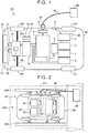
- FIG. 1 schematically shows the configuration of a principal part of a vehicle 100 according to the embodiment.
- the vehicle 100 includes a vehicle electronic control unit (ECU) 1 as a controller, engine 2 as an internal combustion engine, fuel tank 3, fuel filler port 4, motor-generator 5 for power generation, as a generator, inverter 6 for power generation, power storage device 7, connecting part 8, charging device 9, power control unit (PCU) 10, transaxle 11, motor-generator 12 for driving, radiator 13 for engine, radiator 14 for electric system, drive shafts 15L, 15R, front wheels 16L, 16R as driving wheels, rear wheels 17L, 17R as non-driving wheels, air-conditioning equipment 21, audio equipment 22, fuel remaining amount detection sensor 30, user detector 41, interface (which will also be called “I/F”) unit 42, and SOC detection sensor 70.
- Reference numeral 50 in FIG. 1 is an outline of the vehicle 100, which delimits a boundary between the interior and exterior of the vehicle 100.
- the power storage device 7 is an electric power storage element configured to be charged with electric power or discharge power.
- the power storage device 7 includes a secondary battery, such as a lithium-ion battery, nickel hydride battery, or lead storage battery, or a power storage element, such as an electric double layer capacitor.
- the power storage device 7 is connected to the PCU 10 via a power line, for example.
- the power storage device 7 supplies the PCU 10 with electric power for generating driving force in the vehicle 100.
- the power storage device 7 stores electric power generated by the motor-generator 5 for power generation.
- the output of the power storage device 7 is, for example, about 200 V.
- the PCU 10 has a converter (not shown), an inverter (not shown), and so forth.
- the converter of the PCU 10 performs voltage conversion on electric power supplied from the power storage device 7 to the PCU 10, based on a control signal from the vehicle ECU 1.
- the inverter of the PCU 10 converts direct-current (DC) power supplied from the converter, into alternating-current (AC) power, based on a control signal from the vehicle ECU 1, and supplies the AC power to the motor-generator 12 for driving, which is provided in the transaxle 11, so as to drive the motor-generator 12 for driving.
- DC direct-current
- AC alternating-current
- the motor-generator 5 for power generation and the motor-generator 12 for driving are alternating-current rotating electric machines.
- each of the motor-generators 5, 12 is a permanent magnet type synchronous rotating electric machine having a rotor in which permanent magnets are embedded.
- Output torque of the motor-generator 12 for driving is transmitted to the front wheels 16R, 16L, via a power transmission mechanism (not shown) provided in the transaxle 11 and the drive shafts 15R, 15L, so as to propel the vehicle 100.
- the motor-generator 12 for driving can generate electric power, using rotary power of the front wheels 16R, 16L.
- the power generated by the motor-generator 12 for driving is then converted into charging power via the PCU 10, and supplied to the power storage device 7.
- the motor-generator 5 for power generation is connected to the engine 2 via a power transmission mechanism (not shown), and is able to generate electric power when it is driven with driving force from the engine 2.
- the engine 2 is driven with fuel, such as gasoline, supplied from the fuel tank 3.
- fuel such as gasoline
- a fueling nozzle provided in refueling equipment (not shown) is inserted into the fuel filler port 4, and the fuel is fed from the refueling equipment into a fuel pipe via the fueling nozzle, fuel filler port 4, etc.
- the amount of fuel remaining in the fuel tank 3 is detected by the fuel remaining amount detection sensor 30 provided in the fuel tank 3, and the result of detection is transmitted as a control signal to the vehicle ECU 1.
- Electric power generated by the motor-generator 5 for power generation is converted into charging power by means of the inverter 6 for power generation, and supplied to the power storage device 7, so that the power storage device 7 is charged with the power.
- the motor-generator 12 for driving is used exclusively as an electric motor for driving the front wheels 16R, 16L
- the motor-generator 5 for power generation is used exclusively as a generator driven by the engine 2.
- the engine 2 and the motor-generator 5 for power generation constitute a power generation unit.
- the number of motor-generators is not limited to this, but may be any value provided that the vehicle includes a motor-generator capable of generating electric power by use of the engine 2.
- the radiator 13 for engine constitutes a coolant circulation system in which coolant for cooling the engine 2 passes through a cooling pipe and circulates.
- the radiator 14 for electric system constitutes a coolant circulation system in which coolant for cooling an electric system, including the motor-generator 5 for power generation, inverter 6 for power generation, power storage device 7, charging device 9, PCU 10, and motor-generator 12 for driving, is circulated.
- the I/F unit 42 serves as an interface between the user and the vehicle ECU 1. Although not illustrated in the drawings, the I/F unit 42 has an input part for receiving a command from the user, a display part for displaying conditions of each part of devices and warnings to the user, and so forth. The I/F unit 42 transmits an operation signal entered by the user via the input part, to the vehicle ECU 1. Also, the I/F unit 42 displays a content to be presented to the user, on the display part, based on a display signal from the vehicle ECU 1.
- the vehicle ECU 1 has a central processing unit (CPU), storage device, and so forth, which are not illustrated in FIG. 1 .
- the vehicle ECU 1 receives a signal from each sensor, etc. provided in the vehicle 100, outputs a control signal to each device, and controls the vehicle 100 and each device.
- the control is not limited to processing by software, but may be implemented by a dedicated hardware (electronic circuit).
- the vehicle ECU 1 computes the state of charge (SOC) of the power storage device 7, based on detection values of voltage and current from the SOC detection sensor 70 provided in the power storage device 7.
- the vehicle ECU 1 creates control signals for controlling the engine 2, PCU 10, and so forth, and outputs the signals.
- the vehicle 100 has the connecting part 8, charging device 9, etc., as an arrangement for charging the power storage device 7 with electric power from the external power supply 80.
- the charging device 9 is connected to the power storage device 7 and the connecting part 8 via respective power lines, or the like.
- a charging connector 81 of a charging cable 82 provided on the external power supply 80 is connected to the connecting part 8.
- electric power is transmitted from the external power supply 80 to the charging device 9 through the charging cable 82, via the charging connector 81 and the connecting part 8.
- the charging device 9 is controlled according to a control signal from the vehicle ECU 1, so as to convert alternating-current (AC) power supplied from the external power supply 80 via the connecting part 8 into charging power, and supply the power to the power storage device 7, to charge the power storage device 7.
- AC alternating-current
- charging the power storage device 7 with electric power supplied from the external power supply 80 located outside the vehicle is referred to as "external charging”.
- the method of external charging, or charging the power storage device 7 from outside the vehicle is not limited to contact charging where the connecting part 8 of the vehicle 100 is in contact with the charging connector 81 of the external power supply 80, but may be non-contact charging using an electromagnetic induction method or a resonance method.
- While one control unit is provided as the vehicle ECU 1 in the vehicle 100 according to the embodiment, individual control units, such as a control unit for the engine 2 and a control unit for the PCU 10, may be provided for respective functions or devices to be controlled.
- the power storage device 7 can be charged with electric power, through external charging, and charging with power generated by the motor-generator 5 for power generation, which is driven with driving force from the engine 2. The charging of the power storage device 7 is controlled by the vehicle ECU 1 that functions as a charge control device.
- the motor-generator 12 for driving is driven using only electric power from the power storage device 7, so as to propel the vehicle 100.
- the power storage device 7 may be desired to be brought into a fully charged state, immediately before starting. In this case, the user may wish to bring the power storage device 7 into the fully charged state in a short period of time.
- the fully charged state of the power storage device 7 is not limited to the case where the SOC of the power storage device 7 is 100%.
- the power storage device 7 may be regarded as being in the fully charged state when the SOC of the power storage device 7 reaches a preset given SOC, for example, when it is equal to or greater than 90% or 95%.
- the power storage device 7 may also be charged with electric power generated by the motor-generator 5 for power generation by driving the engine 2.
- This type of charging will be called “add-on charging”.
- the power storage device 7 can be charged with electric power from the external power supply 80, and electric power from the motor-generator 5 for power generation, and the power storage device 7 can be brought into the fully charged state in a shorter time than that in the case where the power storage device 7 is charged solely with electric power from the external power supply 80.
- the vehicle 100 is parked in a parking space in the vicinity of the external power supply 80; therefore, the user, as an occupant, such as a driver, of the vehicle 100, may not be present in the interior of the vehicle 100 during external charging.
- the user may not be able to take action at the time of emergency and manage the safety of the vehicle 100 when an abnormality occurs in the vehicle 100, such as when the rotational speed of the engine 2 becomes excessively high.
- the user of the vehicle 100 is not limited to an occupant, such as a driver, of the vehicle 100, but may include a worker who does maintenance work on the vehicle 100, or a staff member who stays at an outside charging facility where the external power supply 80 is installed.
- the vehicle ECU 1 performs charge control, so as to enable add-on charging during external charging, under a situation where the user can take action at the time of emergency and manage the safety of the vehicle 100.
- FIG. 2 shows examples of ranges of the position of the user relative to the vehicle 100, in which add-on charging can be performed during external charging.
- the power storage device 7 is externally charged with electric power from the external power supply 80, in a condition where the vehicle 100 is parked in a parking space 200 delimited by a pair of white lines 201.
- the vehicle ECU 1 determines whether add-on charging can be performed during external charging, depending on whether the user of the vehicle 100 is present within a range surrounding the periphery of a driver seat 91 provided in a cabin of the vehicle 100, namely, in an area A1 defined by a broken line in FIG. 2 , for example, during external charging. More specifically, the user detector 41 shown in FIG. 1 is used for determining whether the user is present in the area A1, during external charging.
- the user detector 41 can detect the user in the area A1, based on various kinds of information, including wearing of a seat belt corresponding to the driver seat 91, image recognition where the driver seat 91 is included in a range of imaging by a camera, history of opening/closing of a door corresponding to the driver seat 91 after stop of the engine, and the history of locking/unlocking of the door corresponding to the driver seat 91, for example. Then, when the user is detected in the area A1 by the user detector 41, the vehicle ECU 1 determines that add-on charging can be performed during external charging. In this manner, the power storage device 7 can be charged by driving the engine 2 and executing add-on charging, during external charging.
- the vehicle ECU 1 may determine whether add-on charging can be performed during external charging, depending on whether the user of the vehicle 100 is present in the cabin of the vehicle 100 in which the driver seat 91, passenger seat 92, and rear seat 93 are provided, namely, in an area A2 defined by a one-dot chain line in FIG. 2 , for example, during external charging.
- the user detector 41 shown in FIG. 1 is used for determining whether the user is present in the area A2, during external charging.
- the user detector 41 can detect the user in the area A2, based on various kinds of information, such as wearing of a seat belt corresponding to each of the driver seat 91, passenger seat 92, and rear seat 93, image recognition where the range of imaging by a camera includes the interior of the cabin, history of opening/closing of each door after stop of the engine, and the history of locking/unlocking of each door.
- the vehicle ECU 1 determines that add-on charging can be performed during external charging. It is thus possible to charge the power storage device 7, by executing add-on charging during external charging.
- the range used by the user detector 41 as the interior of the cabin of the vehicle 100 is not limited to the range as shown in FIG. 2 , in which the driver seat 91, passenger seat 92, and rear seat 93 are provided.
- a range including a luggage room provided on the vehicle rear side of the rear seat 93 and spatially connected with the rear seat 93 may be regarded as the interior of the cabin of the vehicle 100, and the user detector 41 may detect the user in this range.
- add-on charging can be performed during external charging, when the user is present in the interior (such as area A1 and area A2) of the vehicle 100 as a predetermined range relative to the vehicle 100, under a situation where the user can take action in response to an abnormality in the vehicle 100 which occurs during add-on charging in the middle of external charging.
- the user located in the interior of the vehicle 100 can take action at the time of emergency and manage the safety of the vehicle 100 when add-on charging is performed during external charging.
- the vehicle ECU 1 may determine whether add-on charging can be performed during external charging, depending on whether the user of the vehicle 100 is present within a range surrounding the periphery of the vehicle 100 and including a pair of white lines 201 that define the parking space 200 in which the vehicle 100 is parked, and the external power supply 80 that performs external charging on the vehicle 100, namely, within an area A3 defined by a two-dot chain line in FIG. 2 , during external charging.
- the user detector 41 determines whether the user is present in the area A3, during external charging.
- the user detector 41 can detect the user in the area A3, through image recognition where the range of imaging by a camera includes the outer periphery of the vehicle 100, or via wireless communications with a user-side communication device (e.g., a key for the vehicle 100 having a communication function) carried by the user.
- a user-side communication device e.g., a key for the vehicle 100 having a communication function
- the range outside the vehicle 100 which is used for detection by the user detector 41, is not limited to the vehicle-outside range close to the vehicle 100, as shown in FIG. 2 . Rather, the range outside the vehicle 100 may be determined, such that the user located in the range can notice an abnormality when it occurs in the vehicle 100, and can immediately rush over to the vehicle 100, even if the user is relatively far from the vehicle 100.
- the range outside the vehicle 100 may be a range in which the user can visually identify or recognize the vehicle 100, or a range (within a circle centered on the vehicle 100 and having a radius of 100 m to 400 m) in which wireless communications can be conducted via the Bluetooth (registered tradename), between a user-side communication device carried by the user, and a vehicle-side communication device, such as the user detector 41, provided in the vehicle 100.
- the vehicle 100 is parked in a parking space 200 provided in a rest facility or a commercial facility annexed to an expressway, and the user uses the rest facility or commercial facility, during external charging.
- the user may visually notice the abnormality in the vehicle 100, or the vehicle-side communication device may inform the user-side communication device of the abnormality so as to cause the user to be aware of the abnormality in the vehicle 100, so that the user can take action in response to the abnormality in the vehicle 100.
- the user-side communication device and the vehicle-side communication device are in wireless communications with each other, the user is only required to be present within the predetermined range.
- the wireless communications are cut off, or there are no wireless communications in the first place, it may be determined that the user is not present within the predetermined range.
- a notification that add-on charging is being performed, or the engine 2 is being driven for add-on charging may be displayed on a display device (not shown) provided inside the vehicle and/or outside the vehicle, during add-on charging in the middle of external charging.
- a display device not shown
- the user located inside or outside the vehicle 100 can recognize that add-on charging is being performed during external charging or the engine 2 is being driven.
- by displaying a notification that the engine 2 is being driven for add-on charging, toward the outside of the vehicle 100 it is possible to inform a person other than the user of the vehicle 100, of the reason why exhaust gas is emitted from an unoccupied vehicle 100 during external charging, for example.
- the amount of electric power that can be generated from the motor-generator 5 for power generation, during add-on charging in the middle of external charging, may be selectable by the user, depending on circumstances, within a range in which the vehicle 100 can meet various restrictions imposed thereon.
- the amount of reduction of the charging time of external charging may be selected, according to a request of the driver.
- the above-mentioned various restrictions include, for example, the temperatures of the motor-generator 5 for power generation, engine 2, and inverter 6 for power generation, which are estimated from the water temperatures of the radiator 13 for engine and the radiator 14 for electric system, and the amount of fuel remaining in the fuel tank 3, for example.
- FIG. 3 is a view useful for generally describing charge control according to this embodiment.
- the horizontal axis indicates time
- the vertical axis indicates the SOC of the power storage device 7.
- the vehicle 100 is selectively operable in a weak power generation mode and a strong power generation mode, between which the add-on amount of electric power is different.
- the add-on amount is the amount of electric power from the motor-generator 5 for power generation, which is added during add-on charging in the middle of external charging.
- the user can select one of the weak power generation mode and the strong power generation mode, via the I/F unit 42.
- the strong power generation mode the rotational speed of the engine 2 is increased to be higher than that in the weak power generation mode, so that the add-on amount of electric power is increased.
- the add-on amount of electric power which can be set during add-on charging in the middle of external charging is not limited to two levels, but may be selected from three or more levels, or may be a single level.
- Graph G1 in FIG. 3 illustrates the case where external charging is started from the time when the SOC of the power storage device 7 is an empty state (denoted as "EMPTY” in FIG. 3 ), and shows change of the SOC when the power storage device 7 is charged solely with electric power from the external power supply 80, until the SOC reaches full charge (denoted as "FULL” in FIG. 3 ).
- Region EC in FIG. 3 indicates the amount of electric power from the external power supply 80.
- Graph G2 in FIG. 3 illustrates the case where external charging is started from the time when the SOC of the power storage device 7 is the empty state, and shows change of the SOC when the power storage device 7 is charged with both electric power from the external power supply 80, and electric power from the motor-generator 5 for power generation in the weak power generation mode, until the SOC reaches full charge.
- Region GE L in FIG. 3 indicates the amount of electric power from the motor-generator 5 for power generation in the weak power generation mode, namely, the add-on amount of power in the weak power generation mode.
- Graph G3 in FIG. 3 illustrates the case where external charging is started from the time when the SOC of the power storage device 7 is the empty state, and shows change of the SOC when the power storage device 7 is charged with both electric power from the external power supply 80, and electric power from the motor-generator 5 for power generation in the strong power generation mode, until the SOC reaches full charge.
- Region GE H in FIG. 3 indicates the amount of electric power from the motor-generator 5 for power generation in the strong power generation mode, namely, the add-on amount of power in the strong power generation mode.
- the charging time it takes to charge the power storage device 7 from the time when the SOC is the empty state to the time when the SOC is the full state is equal to time T1 (min.).
- the charging time it takes from the time when the SOC is the empty state to the time when the SOC is the full state is equal to time T2 (min.), which is shorter than time T1 (min.).
- the charging time it takes from the time when the SOC is the empty state to the time when the SOC is the full state is equal to time T3 (min.), which is shorter than time T2 (min.).
- arrow A indicates the amount of reduction (time T1 - time T2) of the charging time in the case where add-on charging is performed in the weak power generation mode, as compared with the case where the power storage device 7 is charged solely with electric power from the external power supply 80, during external charging.
- arrow B indicates the amount of reduction (time T1 - time T3) of the charging time in the case where add-on charging is performed in the strong power generation mode, as compared with the case where the power storage device 7 is charged solely with electric power from the external power supply 80, during external charging.
- the vehicle 100 it is possible to reduce the charging time by performing add-on charging during external charging, as compared with the case where the power storage device 7 is charged solely with electric power from the external power supply 80.
- the user selects one of the weak power generation mode and the strong power generation mode, via the I/F unit 42, so that the amount of reduction of the charging time resulting from add-on charging in the middle of external charging can be controlled so as to meet a request of the user.
- the user selects the strong power generation mode via the I/F unit 42.
- the strong power generation mode In the strong power generation mode, however, the rotational speed of the engine 2 is increased, and the fuel economy may be deteriorated.
- the engine 2 is driven at a high rotational speed, noise may create a problem for the environment. Since the engine 2 is driven in a condition where the vehicle 100 is stopped, exhaust gas emitted from the engine 2 may undesirably fill the surroundings of the vehicle 100.
- the user selects the weak power reduction mode via the I/F unit 42.
- the rotational speed of the engine 2 is reduced to be lower than that in the strong power generation mode, and the fuel consumption, noise, and exhaust gas can be reduced, as compared with those in the strong power generation mode.
- Electric power from the motor-generator 5 for power generation generally depends on the rotational speed of the motor-generator 5, in other words, the rotational speed of the engine 2.
- the required electric power from the motor-generator 5 for power generation is larger than electric power that can be generated by the motor-generator 5 when the engine 2 is driven at the above operating point, it is possible to increase the power from the motor-generator 5, by increasing the rotational speed of the engine 2, while sacrificing the power generation efficiency to some extent.
- the amount of electric power from the motor-generator 5 for power generation is almost constant, while the engine 2 is driven and power is generated by the motor-generator 5.
- the manner of driving the engine 2 is not limited to this.
- the engine 2 is driven, so that the power of the motor-generator 5 is maximized within a permissible range, or under a condition that the power generation efficiency is optimized. Then, when it becomes possible to obtain the remaining charging power required to bring the power storage device 7 into the full charge state, solely by use of the power from the external power supply 80, the engine 2 may be stopped in the middle of external charging, and thereafter, the power storage device 7 may be charged solely with the power from the external power supply 80. In this manner, the drive time of the engine 2 can be shortened, and emission of exhaust gas and generation of noise over a long period of time can be curbed or prevented.
- the power storage device 7 may be charged with electric power from the motor-generator 5 for power generation, such that the power is increased by increasing the rotational speed of the engine 2, only for a given period of time during add-on charging in the middle of external charging. In this manner, a balance between the fuel consumption efficiency and the charging time can be selected, so that charging can be performed so as to further meet the user's request.
- the add-on charging may be allowed to be finished according to a request from the user.
- the user can finish the add-on charging, and select, via the I/F unit 42, a mode of external charging only, in which the power storage device 7 is charged solely with electric power from the external power supply 80.
- the vehicle 100 it is not necessarily essential to perform add-on charging during external charging.
- the power storage device 7 may be charged using only electric power from the external power supply 80.
- two or more modes may be provided in advance, depending on whether add-on charging is performed during external charging, and the user may be able to select, via the I/F unit 42, a mode (mode of external charging only) in which the power storage device 7 is charged solely with electric power from the external power supply 80, or a mode (add-on charging mode) in which the power storage device 7 is charged with both the power from the external power supply 80 and power from the motor-generator 5 for power generation.
- a mode mode of external charging only
- add-on charging mode in which the power storage device 7 is charged with both the power from the external power supply 80 and power from the motor-generator 5 for power generation.
- the motor-generator 5 for power generation may be permitted to generate electric power during external charging. This makes it possible to reduce fuel consumption, and secure the predetermined amount of fuel.
- an accessory power supply (ACC power supply) of the vehicle 100 may be turned on, during external charging (namely, the vehicle ECU 1 may permit the accessory power supply of the vehicle 100 to be turned on during external charging).
- the accessory power supply (ACC power supply) thus turned on, comfortable equipment, such as air-conditioning equipment 21 (see FIG. 1 ) and audio equipment 22 (see FIG. 1 ), can be used, during external charging, so as to make the user in the interior of the vehicle 100 more comfortable.
- the motor-generator 5 for power generation can generate electric power during external charging, while the ignition power supply of the vehicle 100 is in the OFF state (namely, the vehicle ECU 1 may permit a generator to generate electric power during external charging, while the ignition power supply of the vehicle 100 is in the OFF state).
- the engine 2 is not driven except when add-on charging is performed, during external charging; therefore, fuel consumption can be reduced, and unintentional driving of the engine 2 can be curbed or prevented.
- FIG. 4 is a flowchart illustrating one example of charge control performed by the vehicle ECU 1.
- the vehicle ECU 1 determines whether external charging is being performed (step S1). In this step, the vehicle ECU 1 can determine whether external charging is being performed, based on a control signal from the charging device 9, for example. When external charging is not being performed (NO in step S1), the vehicle ECU 1 finishes the control routine of FIG. 4 .
- the vehicle ECU 1 determines whether there is a request for add-on charging (step S2). The determination as to the presence or absence of the request for add-on charging can be made, based on the result of selection of the user via the I/F unit 42, about the request for add-on charging.
- step S3 When the vehicle ECU 1 determines the presence of the request for add-on charging (YES in step S2), it starts various determination controls (step S3). Initially, the vehicle ECU 1 determines the presence of the user (step S4). When the vehicle ECU 1 determines that the user of the vehicle 100 is present within a predetermined range (YES in step S5), it starts add-on charging (step S6). Then, the vehicle ECU 1 determines whether there is a sufficient remaining amount of fuel for driving the engine 2 (step S7). When the vehicle ECU 1 determines that there is a sufficient remaining amount of fuel (YES in step S7), it determines whether there is a request for the end of add-on charging from the user (step S8). The determination as to the presence or absence of the request for the end of add-on charging from the user can be made, based on whether the user has selected the end of add-on charging via the I/F unit 42, for example.
- step S10 determines whether the SOC of the power storage device 7 is equal to or larger than a predetermined value.
- the vehicle ECU 1 determines that the SOC of the power storage device 7 is not equal to or larger than the predetermined value (NO in step S10).
- the vehicle ECU 1 determines that the SOC of the power storage device 7 is equal to or larger than the predetermined value (YES in step S10), it finishes charging (step S11), and finishes the control routine of FIG. 4 .
- step S2 determines in step S2 that there is no request for add-on charging (NO in step S2), or when it determines in step S5 that the user is not present within the predetermined range (NO in step S5), the vehicle ECU 1 executes the mode of external charging only (step S13).
- step S7 determines in step S7 that there is not a sufficient remaining amount of fuel (NO in step S7), or when it determines in step S8 that there is a request for the end of add-on charging from the user (YES in step S8), the vehicle ECU 1 finishes add-on charging (step S12), and executes the mode of external charging only (step S13).
- step S14 the vehicle ECU 1 determines whether the SOC of the power storage device 7 is equal to or larger than the predetermined value (step S14).
- the vehicle ECU 1 determines that the SOC of the power storage device 7 is not equal to or larger than the predetermined value (NO in step S14)
- it returns to step S13.
- the vehicle ECU 1 determines that the SOC of the power storage device 7 is equal to or larger than the predetermined value (YES in step S14)
- the engine 2 is driven so as to cause the motor-generator 5 for power generation to generate electric power, during external charging, so that the power storage device 7 can be charged with both electric power from the external power supply 80 and electric power from the motor-generator 5.
- the charging time can be reduced, as compared with the case where the power storage device 7 is charged solely with the power from the external power supply 80.
- add-on charging can be performed during external charging, when the user is present within the predetermined range relative to the vehicle 100, namely, under a situation where the user can take action in response to an abnormality in the vehicle 100, which occurs during add-on charging in the middle of external charging. Also, add-on charging is not performed during external charging, when the user is not present within the predetermined range. Thus, the user is able to take action at the time of emergency and manage the safety of the vehicle 100, when add-on charging is performed during external charging.
Abstract
Description
- The invention relates to a charge control system for a vehicle.
- In a vehicle disclosed in Japanese Patent No.
5661121 JP 5661121 B - However, in the vehicle disclosed in
JP 5661121 B - The invention provides a charge control system for a vehicle, which makes it possible to take action at the time of emergency and manage the safety of the vehicle when an internal combustion engine is driven during external charging so as to cause a generator to generate electric power.
- One aspect of the invention is concerned with a charge control system for a vehicle, which is configured to control charging of a power storage device of the vehicle. The power storage device is adapted to be externally charged with electric power from an outside of the vehicle, and adapted to be charged with electric power generated by a generator that is driven with driving force from an internal combustion engine. The charge control system includes a user detector configured to determine whether a user is present within a predetermined range relative to the vehicle, and a vehicle electronic control unit configured to permit the power storage device to be charged with electric power generated by the generator, in addition to the electric power from the outside of the vehicle, during external charging, when the user detector determines that the user is present within the predetermined range. The vehicle electronic control unit is configured to inhibit power generation by the generator during external charging when the user detector determines that the user is not present within the predetermined range.
- In the charge control system according to the above aspect, the predetermined range may be a range that surrounds a periphery of a driver seat of the vehicle.
- In the charge control system according to the above aspect, the predetermined range may be an interior of the vehicle.
- With the above configuration, since the user is present inside the vehicle, the user is able to take action at the time of emergency and manage the safety of the vehicle when add-on charging is performed during external charging.
- In the charge control system according to the above aspect, the predetermined range may be a range in which wireless communications between the vehicle and a communication device carried by the user are possible.
- With the above configuration, the charge control system can inform the communication device carried by the user of occurrence of an abnormality in the vehicle during external charging. Thus, the user is notified of the abnormality in the vehicle, and is able to take action at the time of emergency and manage the safety of the vehicle when add-on charging is performed during external charging.
- In the charge control system according to the above aspect, whether electric power is generated by the generator during external charging may be selectable by the user.
- With the above configuration, the user can select whether the charging time is to be reduced, or the fuel consumption is to be reduced.
- In the charge control system according to the above aspect, an amount of electric power generated by the generator during external charging may be selectable by the user.
- With the above configuration, the user can select the charging time or the fuel efficiency.
- In the charge control system according to the above aspect, the vehicle electronic control unit may permit the generator to generate electric power during external charging, when a remaining amount of fuel for driving the internal combustion engine in the vehicle is equal to or larger than a predetermined amount.
- With the above configuration, the fuel consumption can be controlled so as to assure the predetermined amount of fuel.
- In the charge control system according to the above aspect, whether power generation by the generator during external charging is continued or finished may be selectable by the user.
- With the above configuration, the user can select reduction of the charging time or reduction of the fuel consumption.
- The charge control system according to the above aspect may further include a display device that indicates that the internal combustion engine is being driven during external charging.
- With the above configuration, the user, etc. can be informed that the internal combustion engine is being driven during external charging.
- In the charge control system according to the above aspect, the vehicle electronic control unit may permit an accessory power supply to be turned on during external charging.
- With the above configuration, air-conditioning equipment, audio equipment, and the like, can be used during charging, so as to make the user located inside the vehicle feel more comfortable.
- In the charge control system according to the above aspect, the vehicle electronic control unit may permit the generator to generate electric power during external charging while an ignition power supply of the vehicle is in an OFF state.
- With the above configuration, the internal combustion engine is not driven except when add-on charging is performed during external charging; therefore, the fuel consumption can be reduced, and unintentional driving of the internal combustion engine can be curbed.
- The charge control system for the vehicle according to the above aspect can drive the internal combustion engine and cause the generator to generate electric power during external charging, only when the user is present within the predetermined range relative to the vehicle, namely, under a situation where the user can take action in response to an abnormality that occurs in the vehicle. Thus, the user who is present within the predetermined range can take action at the time of emergency and manage the safety of the vehicle, when the internal combustion engine is driven so as to cause the generator to generate electric power, during external charging.
- Features, advantages, and technical and industrial significance of exemplary embodiments of the invention will be described below with reference to the accompanying drawings, in which like numerals denote like elements, and wherein:
-
FIG. 1 is a schematic view showing the configuration of a principal part of a vehicle according to one embodiment; -
FIG. 2 is a view showing examples of ranges of the position of a user relative to the vehicle, in which add-on charging can be performed during external charging; -
FIG. 3 is a view useful for generally describing charge control according to the embodiment; and -
FIG. 4 is a flowchart illustrating one example of charge control performed by a vehicle electronic control unit. - A charge control system for a vehicle according to one embodiment of the invention will be described. The invention is not limited to this embodiment.
-
FIG. 1 schematically shows the configuration of a principal part of avehicle 100 according to the embodiment. As shown inFIG. 1 , thevehicle 100 according to this embodiment includes a vehicle electronic control unit (ECU) 1 as a controller,engine 2 as an internal combustion engine,fuel tank 3,fuel filler port 4, motor-generator 5 for power generation, as a generator,inverter 6 for power generation,power storage device 7, connectingpart 8,charging device 9, power control unit (PCU) 10,transaxle 11, motor-generator 12 for driving,radiator 13 for engine,radiator 14 for electric system,drive shafts front wheels rear wheels conditioning equipment 21,audio equipment 22, fuel remainingamount detection sensor 30,user detector 41, interface (which will also be called "I/F")unit 42, andSOC detection sensor 70.Reference numeral 50 inFIG. 1 is an outline of thevehicle 100, which delimits a boundary between the interior and exterior of thevehicle 100. - The
power storage device 7 is an electric power storage element configured to be charged with electric power or discharge power. Thepower storage device 7 includes a secondary battery, such as a lithium-ion battery, nickel hydride battery, or lead storage battery, or a power storage element, such as an electric double layer capacitor. - The
power storage device 7 is connected to the PCU 10 via a power line, for example. Thepower storage device 7 supplies the PCU 10 with electric power for generating driving force in thevehicle 100. Also, thepower storage device 7 stores electric power generated by the motor-generator 5 for power generation. The output of thepower storage device 7 is, for example, about 200 V. - The
PCU 10 has a converter (not shown), an inverter (not shown), and so forth. The converter of the PCU 10 performs voltage conversion on electric power supplied from thepower storage device 7 to the PCU 10, based on a control signal from the vehicle ECU 1. The inverter of the PCU 10 converts direct-current (DC) power supplied from the converter, into alternating-current (AC) power, based on a control signal from the vehicle ECU 1, and supplies the AC power to the motor-generator 12 for driving, which is provided in thetransaxle 11, so as to drive the motor-generator 12 for driving. - The motor-
generator 5 for power generation and the motor-generator 12 for driving are alternating-current rotating electric machines. For example, each of the motor-generators - Output torque of the motor-
generator 12 for driving is transmitted to thefront wheels transaxle 11 and thedrive shafts vehicle 100. When thevehicle 100 performs regenerative braking operation, the motor-generator 12 for driving can generate electric power, using rotary power of thefront wheels generator 12 for driving is then converted into charging power via the PCU 10, and supplied to thepower storage device 7. - The motor-
generator 5 for power generation is connected to theengine 2 via a power transmission mechanism (not shown), and is able to generate electric power when it is driven with driving force from theengine 2. Theengine 2 is driven with fuel, such as gasoline, supplied from thefuel tank 3. To replenish thefuel tank 3 with the fuel, a fueling nozzle provided in refueling equipment (not shown) is inserted into thefuel filler port 4, and the fuel is fed from the refueling equipment into a fuel pipe via the fueling nozzle,fuel filler port 4, etc. The amount of fuel remaining in thefuel tank 3 is detected by the fuel remainingamount detection sensor 30 provided in thefuel tank 3, and the result of detection is transmitted as a control signal to the vehicle ECU 1. - Electric power generated by the motor-
generator 5 for power generation is converted into charging power by means of theinverter 6 for power generation, and supplied to thepower storage device 7, so that thepower storage device 7 is charged with the power. In this embodiment, the motor-generator 12 for driving is used exclusively as an electric motor for driving thefront wheels generator 5 for power generation is used exclusively as a generator driven by theengine 2. Namely, in this embodiment, theengine 2 and the motor-generator 5 for power generation constitute a power generation unit. - While the
vehicle 100 is equipped with two motor-generators in the embodiment ofFIG. 1 , the number of motor-generators is not limited to this, but may be any value provided that the vehicle includes a motor-generator capable of generating electric power by use of theengine 2. - The
radiator 13 for engine constitutes a coolant circulation system in which coolant for cooling theengine 2 passes through a cooling pipe and circulates. Theradiator 14 for electric system constitutes a coolant circulation system in which coolant for cooling an electric system, including the motor-generator 5 for power generation,inverter 6 for power generation,power storage device 7, chargingdevice 9,PCU 10, and motor-generator 12 for driving, is circulated. - The I/
F unit 42 serves as an interface between the user and the vehicle ECU 1. Although not illustrated in the drawings, the I/F unit 42 has an input part for receiving a command from the user, a display part for displaying conditions of each part of devices and warnings to the user, and so forth. The I/F unit 42 transmits an operation signal entered by the user via the input part, to the vehicle ECU 1. Also, the I/F unit 42 displays a content to be presented to the user, on the display part, based on a display signal from the vehicle ECU 1. - The vehicle ECU 1 has a central processing unit (CPU), storage device, and so forth, which are not illustrated in
FIG. 1 . The vehicle ECU 1 receives a signal from each sensor, etc. provided in thevehicle 100, outputs a control signal to each device, and controls thevehicle 100 and each device. The control is not limited to processing by software, but may be implemented by a dedicated hardware (electronic circuit). The vehicle ECU 1 computes the state of charge (SOC) of thepower storage device 7, based on detection values of voltage and current from theSOC detection sensor 70 provided in thepower storage device 7. The vehicle ECU 1 creates control signals for controlling theengine 2,PCU 10, and so forth, and outputs the signals. - The
vehicle 100 has the connectingpart 8, chargingdevice 9, etc., as an arrangement for charging thepower storage device 7 with electric power from theexternal power supply 80. The chargingdevice 9 is connected to thepower storage device 7 and the connectingpart 8 via respective power lines, or the like. A chargingconnector 81 of a chargingcable 82 provided on theexternal power supply 80 is connected to the connectingpart 8. In operation, electric power is transmitted from theexternal power supply 80 to thecharging device 9 through the chargingcable 82, via the chargingconnector 81 and the connectingpart 8. The chargingdevice 9 is controlled according to a control signal from the vehicle ECU 1, so as to convert alternating-current (AC) power supplied from theexternal power supply 80 via the connectingpart 8 into charging power, and supply the power to thepower storage device 7, to charge thepower storage device 7. In this embodiment, charging thepower storage device 7 with electric power supplied from theexternal power supply 80 located outside the vehicle is referred to as "external charging". Also, the method of external charging, or charging thepower storage device 7 from outside the vehicle, is not limited to contact charging where the connectingpart 8 of thevehicle 100 is in contact with the chargingconnector 81 of theexternal power supply 80, but may be non-contact charging using an electromagnetic induction method or a resonance method. - While one control unit is provided as the vehicle ECU 1 in the
vehicle 100 according to the embodiment, individual control units, such as a control unit for theengine 2 and a control unit for thePCU 10, may be provided for respective functions or devices to be controlled. Also, in thevehicle 100 according to the embodiment, thepower storage device 7 can be charged with electric power, through external charging, and charging with power generated by the motor-generator 5 for power generation, which is driven with driving force from theengine 2. The charging of thepower storage device 7 is controlled by the vehicle ECU 1 that functions as a charge control device. - In the
vehicle 100 according to the embodiment, the motor-generator 12 for driving is driven using only electric power from thepower storage device 7, so as to propel thevehicle 100. Thus, when there is a relatively long distance between a start point to a target point, for example, thepower storage device 7 may be desired to be brought into a fully charged state, immediately before starting. In this case, the user may wish to bring thepower storage device 7 into the fully charged state in a short period of time. In this embodiment, the fully charged state of thepower storage device 7 is not limited to the case where the SOC of thepower storage device 7 is 100%. For example, thepower storage device 7 may be regarded as being in the fully charged state when the SOC of thepower storage device 7 reaches a preset given SOC, for example, when it is equal to or greater than 90% or 95%. - Thus, in the
vehicle 100 according to this embodiment, during external charging of thepower storage device 7 with electric power from theexternal power supply 80, thepower storage device 7 may also be charged with electric power generated by the motor-generator 5 for power generation by driving theengine 2. This type of charging will be called "add-on charging". In this manner, thepower storage device 7 can be charged with electric power from theexternal power supply 80, and electric power from the motor-generator 5 for power generation, and thepower storage device 7 can be brought into the fully charged state in a shorter time than that in the case where thepower storage device 7 is charged solely with electric power from theexternal power supply 80. - In the meantime, during external charging, the
vehicle 100 is parked in a parking space in the vicinity of theexternal power supply 80; therefore, the user, as an occupant, such as a driver, of thevehicle 100, may not be present in the interior of thevehicle 100 during external charging. Thus, when theengine 2 is driven, so as to perform add-on charging during external charging, the user may not be able to take action at the time of emergency and manage the safety of thevehicle 100 when an abnormality occurs in thevehicle 100, such as when the rotational speed of theengine 2 becomes excessively high. - The user of the
vehicle 100 is not limited to an occupant, such as a driver, of thevehicle 100, but may include a worker who does maintenance work on thevehicle 100, or a staff member who stays at an outside charging facility where theexternal power supply 80 is installed. - Thus, in the
vehicle 100 according to the embodiment, the vehicle ECU 1 performs charge control, so as to enable add-on charging during external charging, under a situation where the user can take action at the time of emergency and manage the safety of thevehicle 100. -
FIG. 2 shows examples of ranges of the position of the user relative to thevehicle 100, in which add-on charging can be performed during external charging. InFIG. 2 , thepower storage device 7 is externally charged with electric power from theexternal power supply 80, in a condition where thevehicle 100 is parked in aparking space 200 delimited by a pair ofwhite lines 201. - In the
vehicle 100 according to the embodiment, the vehicle ECU 1 determines whether add-on charging can be performed during external charging, depending on whether the user of thevehicle 100 is present within a range surrounding the periphery of adriver seat 91 provided in a cabin of thevehicle 100, namely, in an area A1 defined by a broken line inFIG. 2 , for example, during external charging. More specifically, theuser detector 41 shown inFIG. 1 is used for determining whether the user is present in the area A1, during external charging. Theuser detector 41 can detect the user in the area A1, based on various kinds of information, including wearing of a seat belt corresponding to thedriver seat 91, image recognition where thedriver seat 91 is included in a range of imaging by a camera, history of opening/closing of a door corresponding to thedriver seat 91 after stop of the engine, and the history of locking/unlocking of the door corresponding to thedriver seat 91, for example. Then, when the user is detected in the area A1 by theuser detector 41, the vehicle ECU 1 determines that add-on charging can be performed during external charging. In this manner, thepower storage device 7 can be charged by driving theengine 2 and executing add-on charging, during external charging. Even if an abnormality, such as an excessive rise in the rotational speed of theengine 2, occurs in thevehicle 100, when theengine 2 is driven for add-on charging in the middle of external charging, the user, who is present in the area A1, namely, on thedriver seat 91, can take action in response to the abnormality. - During external charging, the driver as the user may move from the
driver seat 91 to apassenger seat 92,rear seat 93, or the like, and take a break, rather than being seated on thedriver seat 91. Also, another user may be seated on thepassenger seat 92 orrear seat 93, even if the driver is outside the vehicle, away from thedriver seat 91. Thus, in thevehicle 100 according to the embodiment, the vehicle ECU 1 may determine whether add-on charging can be performed during external charging, depending on whether the user of thevehicle 100 is present in the cabin of thevehicle 100 in which thedriver seat 91,passenger seat 92, andrear seat 93 are provided, namely, in an area A2 defined by a one-dot chain line inFIG. 2 , for example, during external charging. - More specifically, the
user detector 41 shown inFIG. 1 is used for determining whether the user is present in the area A2, during external charging. Theuser detector 41 can detect the user in the area A2, based on various kinds of information, such as wearing of a seat belt corresponding to each of thedriver seat 91,passenger seat 92, andrear seat 93, image recognition where the range of imaging by a camera includes the interior of the cabin, history of opening/closing of each door after stop of the engine, and the history of locking/unlocking of each door. Then, when the user is detected in the area A2 by theuser detector 41, the vehicle ECU 1 determines that add-on charging can be performed during external charging. It is thus possible to charge thepower storage device 7, by executing add-on charging during external charging. Even if an abnormality, such as an excessive rise in the rotational speed of theengine 2, occurs in thevehicle 100, when theengine 2 is driven for add-on charging in the middle of external charging, the user, who is present in the area A2, namely, in the cabin of thevehicle 100, can take action in response to the abnormality. - The range used by the
user detector 41 as the interior of the cabin of thevehicle 100 is not limited to the range as shown inFIG. 2 , in which thedriver seat 91,passenger seat 92, andrear seat 93 are provided. For example, a range including a luggage room provided on the vehicle rear side of therear seat 93 and spatially connected with therear seat 93 may be regarded as the interior of the cabin of thevehicle 100, and theuser detector 41 may detect the user in this range. - Namely, in the
vehicle 100 according to the embodiment, add-on charging can be performed during external charging, when the user is present in the interior (such as area A1 and area A2) of thevehicle 100 as a predetermined range relative to thevehicle 100, under a situation where the user can take action in response to an abnormality in thevehicle 100 which occurs during add-on charging in the middle of external charging. Thus, the user located in the interior of thevehicle 100 can take action at the time of emergency and manage the safety of thevehicle 100 when add-on charging is performed during external charging. - Also, during external charging, the user, such as a driver, may get out of the vehicle, and take a break in the vicinity of the
parking space 200 or near theexternal power supply 80. Thus, in thevehicle 100 according to the embodiment, the vehicle ECU 1 may determine whether add-on charging can be performed during external charging, depending on whether the user of thevehicle 100 is present within a range surrounding the periphery of thevehicle 100 and including a pair ofwhite lines 201 that define theparking space 200 in which thevehicle 100 is parked, and theexternal power supply 80 that performs external charging on thevehicle 100, namely, within an area A3 defined by a two-dot chain line inFIG. 2 , during external charging. - More specifically, the
user detector 41 as shown inFIG. 1 determines whether the user is present in the area A3, during external charging. Theuser detector 41 can detect the user in the area A3, through image recognition where the range of imaging by a camera includes the outer periphery of thevehicle 100, or via wireless communications with a user-side communication device (e.g., a key for thevehicle 100 having a communication function) carried by the user. Then, when the user is detected in the area A3 by theuser detector 41, the vehicle ECU 1 determines that add-on charging can be performed during external charging. It is thus possible to charge thepower storage device 7 by executing add-on charging during external charging. Even if an abnormality, such as an excessive rise in the rotational speed of theengine 2, occurs in thevehicle 100, when theengine 2 is driven for add-on charging in the middle of external charging, the user can take action in response to the abnormality, since he/she is present in the area A3, namely, close to thevehicle 100 though he/she is outside thevehicle 100. - The range outside the
vehicle 100, which is used for detection by theuser detector 41, is not limited to the vehicle-outside range close to thevehicle 100, as shown inFIG. 2 . Rather, the range outside thevehicle 100 may be determined, such that the user located in the range can notice an abnormality when it occurs in thevehicle 100, and can immediately rush over to thevehicle 100, even if the user is relatively far from thevehicle 100. For example, the range outside thevehicle 100 may be a range in which the user can visually identify or recognize thevehicle 100, or a range (within a circle centered on thevehicle 100 and having a radius of 100 m to 400 m) in which wireless communications can be conducted via the Bluetooth (registered tradename), between a user-side communication device carried by the user, and a vehicle-side communication device, such as theuser detector 41, provided in thevehicle 100. As an example of the case where the user is present in the vehicle-outside range as described above, thevehicle 100 is parked in aparking space 200 provided in a rest facility or a commercial facility annexed to an expressway, and the user uses the rest facility or commercial facility, during external charging. Then, when an abnormality occurs in thevehicle 100, during add-on charging in the middle of external charging, the user may visually notice the abnormality in thevehicle 100, or the vehicle-side communication device may inform the user-side communication device of the abnormality so as to cause the user to be aware of the abnormality in thevehicle 100, so that the user can take action in response to the abnormality in thevehicle 100. - When the user-side communication device and the vehicle-side communication device are in wireless communications with each other, the user is only required to be present within the predetermined range. When the wireless communications are cut off, or there are no wireless communications in the first place, it may be determined that the user is not present within the predetermined range.
- In the
vehicle 100 according to this embodiment, a notification that add-on charging is being performed, or theengine 2 is being driven for add-on charging, may be displayed on a display device (not shown) provided inside the vehicle and/or outside the vehicle, during add-on charging in the middle of external charging. In this manner, the user located inside or outside thevehicle 100 can recognize that add-on charging is being performed during external charging or theengine 2 is being driven. In particular, by displaying a notification that theengine 2 is being driven for add-on charging, toward the outside of thevehicle 100, it is possible to inform a person other than the user of thevehicle 100, of the reason why exhaust gas is emitted from anunoccupied vehicle 100 during external charging, for example. - The amount of electric power that can be generated from the motor-
generator 5 for power generation, during add-on charging in the middle of external charging, may be selectable by the user, depending on circumstances, within a range in which thevehicle 100 can meet various restrictions imposed thereon. Thus, the amount of reduction of the charging time of external charging may be selected, according to a request of the driver. The above-mentioned various restrictions include, for example, the temperatures of the motor-generator 5 for power generation,engine 2, andinverter 6 for power generation, which are estimated from the water temperatures of theradiator 13 for engine and theradiator 14 for electric system, and the amount of fuel remaining in thefuel tank 3, for example. -
FIG. 3 is a view useful for generally describing charge control according to this embodiment. InFIG. 3 , the horizontal axis indicates time, and the vertical axis indicates the SOC of thepower storage device 7. - The
vehicle 100 according to the embodiment is selectively operable in a weak power generation mode and a strong power generation mode, between which the add-on amount of electric power is different. The add-on amount is the amount of electric power from the motor-generator 5 for power generation, which is added during add-on charging in the middle of external charging. The user can select one of the weak power generation mode and the strong power generation mode, via the I/F unit 42. In the strong power generation mode, the rotational speed of theengine 2 is increased to be higher than that in the weak power generation mode, so that the add-on amount of electric power is increased. In this connection, the add-on amount of electric power which can be set during add-on charging in the middle of external charging is not limited to two levels, but may be selected from three or more levels, or may be a single level. - Graph G1 in
FIG. 3 illustrates the case where external charging is started from the time when the SOC of thepower storage device 7 is an empty state (denoted as "EMPTY" inFIG. 3 ), and shows change of the SOC when thepower storage device 7 is charged solely with electric power from theexternal power supply 80, until the SOC reaches full charge (denoted as "FULL" inFIG. 3 ). Region EC inFIG. 3 indicates the amount of electric power from theexternal power supply 80. - Graph G2 in
FIG. 3 illustrates the case where external charging is started from the time when the SOC of thepower storage device 7 is the empty state, and shows change of the SOC when thepower storage device 7 is charged with both electric power from theexternal power supply 80, and electric power from the motor-generator 5 for power generation in the weak power generation mode, until the SOC reaches full charge. Region GEL inFIG. 3 indicates the amount of electric power from the motor-generator 5 for power generation in the weak power generation mode, namely, the add-on amount of power in the weak power generation mode. - Graph G3 in
FIG. 3 illustrates the case where external charging is started from the time when the SOC of thepower storage device 7 is the empty state, and shows change of the SOC when thepower storage device 7 is charged with both electric power from theexternal power supply 80, and electric power from the motor-generator 5 for power generation in the strong power generation mode, until the SOC reaches full charge. Region GEH inFIG. 3 indicates the amount of electric power from the motor-generator 5 for power generation in the strong power generation mode, namely, the add-on amount of power in the strong power generation mode. - As shown in
FIG. 3 , when thepower storage device 7 is charged solely with electric power from theexternal power supply 80 during external charging, the charging time it takes to charge thepower storage device 7 from the time when the SOC is the empty state to the time when the SOC is the full state (point P1 on the graph G1 inFIG. 3 ) is equal to time T1 (min.). - Also, when add-on charging is performed in the weak power generation mode during external charging, the charging time it takes from the time when the SOC is the empty state to the time when the SOC is the full state (point P2 on the graph G2 in
FIG. 3 ) is equal to time T2 (min.), which is shorter than time T1 (min.). - Also, when add-on charging is performed in the strong power generation mode during external charging, the charging time it takes from the time when the SOC is the empty state to the time when the SOC is the full state (point P3 on the graph G3 in
FIG. 3 ) is equal to time T3 (min.), which is shorter than time T2 (min.). - In
FIG. 3 , arrow A indicates the amount of reduction (time T1 - time T2) of the charging time in the case where add-on charging is performed in the weak power generation mode, as compared with the case where thepower storage device 7 is charged solely with electric power from theexternal power supply 80, during external charging. Also, arrow B indicates the amount of reduction (time T1 - time T3) of the charging time in the case where add-on charging is performed in the strong power generation mode, as compared with the case where thepower storage device 7 is charged solely with electric power from theexternal power supply 80, during external charging. - As is understood from
FIG. 3 , in thevehicle 100 according to the embodiment, it is possible to reduce the charging time by performing add-on charging during external charging, as compared with the case where thepower storage device 7 is charged solely with electric power from theexternal power supply 80. - Also, the user selects one of the weak power generation mode and the strong power generation mode, via the I/
F unit 42, so that the amount of reduction of the charging time resulting from add-on charging in the middle of external charging can be controlled so as to meet a request of the user. - For example, when the user wishes to reduce the charging time of external charging as much as possible, the user selects the strong power generation mode via the I/
F unit 42. In the strong power generation mode, however, the rotational speed of theengine 2 is increased, and the fuel economy may be deteriorated. Also, if theengine 2 is driven at a high rotational speed, noise may create a problem for the environment. Since theengine 2 is driven in a condition where thevehicle 100 is stopped, exhaust gas emitted from theengine 2 may undesirably fill the surroundings of thevehicle 100. Thus, when the user wishes to reduce fuel consumption, noise and exhaust gas, the user selects the weak power reduction mode via the I/F unit 42. As a result, the rotational speed of theengine 2 is reduced to be lower than that in the strong power generation mode, and the fuel consumption, noise, and exhaust gas can be reduced, as compared with those in the strong power generation mode. - Electric power from the motor-
generator 5 for power generation generally depends on the rotational speed of the motor-generator 5, in other words, the rotational speed of theengine 2. In either of the weak power generation mode and the strong power generation mode, it is desirable, in principle, to drive theengine 2 at an operating point having the highest efficiency (the highest fuel efficiency) to provide the required power in each mode. Meanwhile, when the required electric power from the motor-generator 5 for power generation is larger than electric power that can be generated by the motor-generator 5 when theengine 2 is driven at the above operating point, it is possible to increase the power from the motor-generator 5, by increasing the rotational speed of theengine 2, while sacrificing the power generation efficiency to some extent. - Also, in the example of
FIG. 3 , the amount of electric power from the motor-generator 5 for power generation is almost constant, while theengine 2 is driven and power is generated by the motor-generator 5. However, the manner of driving theengine 2 is not limited to this. - For example, in a period in which both the power from the
external power supply 80 and the power from the motor-generator 5 for power generation are used, during external charging, theengine 2 is driven, so that the power of the motor-generator 5 is maximized within a permissible range, or under a condition that the power generation efficiency is optimized. Then, when it becomes possible to obtain the remaining charging power required to bring thepower storage device 7 into the full charge state, solely by use of the power from theexternal power supply 80, theengine 2 may be stopped in the middle of external charging, and thereafter, thepower storage device 7 may be charged solely with the power from theexternal power supply 80. In this manner, the drive time of theengine 2 can be shortened, and emission of exhaust gas and generation of noise over a long period of time can be curbed or prevented. - Also, the
power storage device 7 may be charged with electric power from the motor-generator 5 for power generation, such that the power is increased by increasing the rotational speed of theengine 2, only for a given period of time during add-on charging in the middle of external charging. In this manner, a balance between the fuel consumption efficiency and the charging time can be selected, so that charging can be performed so as to further meet the user's request. - In the
vehicle 100 according to the embodiment, during add-on charging in the middle of external charging, the add-on charging may be allowed to be finished according to a request from the user. For example, when the user does not want fuel to be consumed by driving theengine 2 while add-on charging is being performed during external charging, the user can finish the add-on charging, and select, via the I/F unit 42, a mode of external charging only, in which thepower storage device 7 is charged solely with electric power from theexternal power supply 80. - In the
vehicle 100 according to the embodiment, it is not necessarily essential to perform add-on charging during external charging. For example, when the user does not want fuel to be consumed to drive theengine 2 so as to cause the motor-generator 5 for power generation to generate electric power, thepower storage device 7 may be charged using only electric power from theexternal power supply 80. To this end, in thevehicle 100 according to the embodiment, two or more modes may be provided in advance, depending on whether add-on charging is performed during external charging, and the user may be able to select, via the I/F unit 42, a mode (mode of external charging only) in which thepower storage device 7 is charged solely with electric power from theexternal power supply 80, or a mode (add-on charging mode) in which thepower storage device 7 is charged with both the power from theexternal power supply 80 and power from the motor-generator 5 for power generation. - In the
vehicle 100 according to the embodiment, when the remaining amount of the fuel for driving theengine 2 in thefuel tank 3 is equal to or larger than a predetermined amount, the motor-generator 5 for power generation may be permitted to generate electric power during external charging. This makes it possible to reduce fuel consumption, and secure the predetermined amount of fuel. - In the
vehicle 100 according to the embodiment, an accessory power supply (ACC power supply) of thevehicle 100 may be turned on, during external charging (namely, the vehicle ECU 1 may permit the accessory power supply of thevehicle 100 to be turned on during external charging). With the accessory power supply (ACC power supply) thus turned on, comfortable equipment, such as air-conditioning equipment 21 (seeFIG. 1 ) and audio equipment 22 (seeFIG. 1 ), can be used, during external charging, so as to make the user in the interior of thevehicle 100 more comfortable. - In the
vehicle 100 according to the embodiment, the motor-generator 5 for power generation can generate electric power during external charging, while the ignition power supply of thevehicle 100 is in the OFF state (namely, the vehicle ECU 1 may permit a generator to generate electric power during external charging, while the ignition power supply of thevehicle 100 is in the OFF state). With this arrangement, theengine 2 is not driven except when add-on charging is performed, during external charging; therefore, fuel consumption can be reduced, and unintentional driving of theengine 2 can be curbed or prevented. -
FIG. 4 is a flowchart illustrating one example of charge control performed by the vehicle ECU 1. Initially, the vehicle ECU 1 determines whether external charging is being performed (step S1). In this step, the vehicle ECU 1 can determine whether external charging is being performed, based on a control signal from the chargingdevice 9, for example. When external charging is not being performed (NO in step S1), the vehicle ECU 1 finishes the control routine ofFIG. 4 . On the other hand, when external charging is being performed (YES in step S1), the vehicle ECU 1 determines whether there is a request for add-on charging (step S2). The determination as to the presence or absence of the request for add-on charging can be made, based on the result of selection of the user via the I/F unit 42, about the request for add-on charging. - When the vehicle ECU 1 determines the presence of the request for add-on charging (YES in step S2), it starts various determination controls (step S3). Initially, the vehicle ECU 1 determines the presence of the user (step S4). When the vehicle ECU 1 determines that the user of the
vehicle 100 is present within a predetermined range (YES in step S5), it starts add-on charging (step S6). Then, the vehicle ECU 1 determines whether there is a sufficient remaining amount of fuel for driving the engine 2 (step S7). When the vehicle ECU 1 determines that there is a sufficient remaining amount of fuel (YES in step S7), it determines whether there is a request for the end of add-on charging from the user (step S8). The determination as to the presence or absence of the request for the end of add-on charging from the user can be made, based on whether the user has selected the end of add-on charging via the I/F unit 42, for example. - When the vehicle ECU 1 determines that there is no request for the end of add-on charging from the user (NO in step S8), it continues add-on charging (step S9). Then, the vehicle ECU 1 determines whether the SOC of the
power storage device 7 is equal to or larger than a predetermined value (step S10). When the vehicle ECU 1 determines that the SOC of thepower storage device 7 is not equal to or larger than the predetermined value (NO in step S10), it returns to step S7. On the other hand, when the vehicle ECU 1 determines that the SOC of thepower storage device 7 is equal to or larger than the predetermined value (YES in step S10), it finishes charging (step S11), and finishes the control routine ofFIG. 4 . - When the vehicle ECU 1 determines in step S2 that there is no request for add-on charging (NO in step S2), or when it determines in step S5 that the user is not present within the predetermined range (NO in step S5), the vehicle ECU 1 executes the mode of external charging only (step S13).
- Also, when the vehicle ECU 1 determines in step S7 that there is not a sufficient remaining amount of fuel (NO in step S7), or when it determines in step S8 that there is a request for the end of add-on charging from the user (YES in step S8), the vehicle ECU 1 finishes add-on charging (step S12), and executes the mode of external charging only (step S13).
- Then, after executing step S13, the vehicle ECU 1 determines whether the SOC of the
power storage device 7 is equal to or larger than the predetermined value (step S14). When the vehicle ECU 1 determines that the SOC of thepower storage device 7 is not equal to or larger than the predetermined value (NO in step S14), it returns to step S13. On the other hand, when the vehicle ECU 1 determines that the SOC of thepower storage device 7 is equal to or larger than the predetermined value (YES in step S14), it finishes charging (step S11), and finishes the control routine ofFIG. 4 . - As described above, in the
vehicle 100 according to the embodiment, theengine 2 is driven so as to cause the motor-generator 5 for power generation to generate electric power, during external charging, so that thepower storage device 7 can be charged with both electric power from theexternal power supply 80 and electric power from the motor-generator 5. Thus, the charging time can be reduced, as compared with the case where thepower storage device 7 is charged solely with the power from theexternal power supply 80. - Also, in the
vehicle 100 according to the embodiment, add-on charging can be performed during external charging, when the user is present within the predetermined range relative to thevehicle 100, namely, under a situation where the user can take action in response to an abnormality in thevehicle 100, which occurs during add-on charging in the middle of external charging. Also, add-on charging is not performed during external charging, when the user is not present within the predetermined range. Thus, the user is able to take action at the time of emergency and manage the safety of thevehicle 100, when add-on charging is performed during external charging.
Claims (11)
- A charge control system for a vehicle (100), the charge control system being configured to control charging of a power storage device (7) of the vehicle (100), the power storage device (7) being adapted to be externally charged with electric power from an outside of the vehicle, and adapted to be charged with electric power generated by a generator that is driven with driving force from an internal combustion engine, the charge control system comprising:a user detector (41) configured to determine whether a user is present within a predetermined range relative to the vehicle (100); anda vehicle electronic control unit configured to permit the power storage device (7) to be charged with electric power generated by the generator, in addition to the electric power from the outside of the vehicle, during external charging, when the user detector (41) determines that the user is present within the predetermined range, the vehicle electronic control unit being configured to inhibit power generation by the generator during external charging when the user detector (41) determines that the user is not present within the predetermined range.
- The charge control system according to claim 1, wherein the predetermined range is a range that surrounds a periphery of a driver seat of the vehicle (100).
- The charge control system according to claim 1, wherein the predetermined range is an interior of the vehicle (100).
- The charge control system according to claim 1, wherein the predetermined range is a range in which wireless communications between the vehicle and a communication device carried by the user are possible.
- The charge control system according to any one of claims 1 to 4, wherein whether electric power is generated by the generator during external charging is selectable by the user.
- The charge control system according to any one of claims 1 to 5, wherein an amount of electric power generated by the generator during external charging is selectable by the user.
- The charge control system according to any one of claims 1 to 6, wherein the vehicle electronic control unit permits the generator to generate electric power during external charging, when a remaining amount of fuel for driving the internal combustion engine in the vehicle (100) is equal to or larger than a predetermined amount.
- The charge control system according to any one of claims 1 to 7, wherein whether power generation by the generator during external charging is continued or finished is selectable by the user.
- The charge control system according to any one of claims 1 to 8, further comprising a display device that indicates that the internal combustion engine is being driven during external charging.
- The charge control system according to any one of claims 1 to 9, wherein the vehicle electronic control unit permits an accessory power supply to be turned on during external charging.
- The charge control system according to any one of claims 1 to 10, wherein the vehicle electronic control unit permits the generator to generate electric power during external charging while an ignition power supply of the vehicle (100) is in an OFF state.
Applications Claiming Priority (1)
| Application Number | Priority Date | Filing Date | Title |
|---|---|---|---|
| JP2018207669A JP2020070000A (en) | 2018-11-02 | 2018-11-02 | Charge control system for vehicle |
Publications (2)
| Publication Number | Publication Date |
|---|---|
| EP3650263A1 true EP3650263A1 (en) | 2020-05-13 |
| EP3650263B1 EP3650263B1 (en) | 2021-08-11 |
Family
ID=68296061
Family Applications (1)
| Application Number | Title | Priority Date | Filing Date |
|---|---|---|---|
| EP19203992.3A Active EP3650263B1 (en) | 2018-11-02 | 2019-10-18 | Charge control system for vehicle |
Country Status (5)
| Country | Link |
|---|---|
| US (1) | US11214166B2 (en) |
| EP (1) | EP3650263B1 (en) |
| JP (1) | JP2020070000A (en) |
| KR (1) | KR20200050860A (en) |
| CN (1) | CN111137143A (en) |
Families Citing this family (4)
| Publication number | Priority date | Publication date | Assignee | Title |
|---|---|---|---|---|
| US11130409B1 (en) * | 2017-11-30 | 2021-09-28 | Hydro-Gear Limited Partnership | Automatic performance learning system for utility vehicles |
| JP7124736B2 (en) * | 2019-01-30 | 2022-08-24 | トヨタ自動車株式会社 | Mounting structure of drive unit in series hybrid vehicle |
| EP3863311A1 (en) * | 2020-02-04 | 2021-08-11 | Knorr-Bremse Gesellschaft mit beschränkter Haftung | Method and device for testing an entry system for a vehicle |
| JP7283459B2 (en) * | 2020-11-12 | 2023-05-30 | トヨタ自動車株式会社 | Charging control system, charging control device and charging control program |
Citations (4)
| Publication number | Priority date | Publication date | Assignee | Title |
|---|---|---|---|---|
| JPH11178109A (en) * | 1997-12-04 | 1999-07-02 | Toyota Motor Corp | Hybrid driver |
| US8204638B2 (en) * | 2008-06-19 | 2012-06-19 | Denso Corporation | Control apparatus for a hybrid vehicle |
| EP2641772A1 (en) * | 2010-11-18 | 2013-09-25 | Toyota Jidosha Kabushiki Kaisha | Vehicle and method for controlling vehicle |
| WO2015145938A1 (en) * | 2014-03-27 | 2015-10-01 | Toyota Jidosha Kabushiki Kaisha | Hybrid vehicle and method of controlling the same |
Family Cites Families (10)
| Publication number | Priority date | Publication date | Assignee | Title |
|---|---|---|---|---|
| JPH0988656A (en) | 1995-09-28 | 1997-03-31 | Mitsubishi Motors Corp | Driving output stop device for vehicle |
| JP4015041B2 (en) * | 2003-02-28 | 2007-11-28 | 株式会社デンソー | Self-diagnosis device for vehicles |
| JP2008104300A (en) * | 2006-10-19 | 2008-05-01 | Toyota Motor Corp | Dew condensation prevention device for detector detecting state of electricity storage system |
| JP4333798B2 (en) * | 2007-11-30 | 2009-09-16 | トヨタ自動車株式会社 | Charge control device and charge control method |
| JP5479999B2 (en) * | 2010-04-28 | 2014-04-23 | トヨタ自動車株式会社 | Vehicle power supply |
| DE102010040239A1 (en) * | 2010-09-03 | 2012-03-08 | Bayerische Motoren Werke Aktiengesellschaft | System for charging a rechargeable battery of an electric vehicle |
| JP5825288B2 (en) * | 2013-04-08 | 2015-12-02 | トヨタ自動車株式会社 | Hybrid vehicle |
| JP2015040011A (en) * | 2013-08-23 | 2015-03-02 | トヨタ自動車株式会社 | Vehicle and power supply system |
| DE102018213768A1 (en) * | 2018-08-16 | 2020-02-20 | Audi Ag | Method for charging a battery of a motor vehicle by means of an external charging station and motor vehicle that is designed to carry out such a method |
| US11383614B2 (en) * | 2019-10-01 | 2022-07-12 | Ford Global Technologies, Llc | Vehicle battery power management systems and methods |
-
2018
- 2018-11-02 JP JP2018207669A patent/JP2020070000A/en active Pending
-
2019
- 2019-10-08 KR KR1020190124848A patent/KR20200050860A/en not_active Application Discontinuation
- 2019-10-08 US US16/596,044 patent/US11214166B2/en active Active
- 2019-10-18 EP EP19203992.3A patent/EP3650263B1/en active Active
- 2019-10-24 CN CN201911016730.XA patent/CN111137143A/en active Pending
Patent Citations (5)
| Publication number | Priority date | Publication date | Assignee | Title |
|---|---|---|---|---|
| JPH11178109A (en) * | 1997-12-04 | 1999-07-02 | Toyota Motor Corp | Hybrid driver |
| US8204638B2 (en) * | 2008-06-19 | 2012-06-19 | Denso Corporation | Control apparatus for a hybrid vehicle |
| EP2641772A1 (en) * | 2010-11-18 | 2013-09-25 | Toyota Jidosha Kabushiki Kaisha | Vehicle and method for controlling vehicle |
| JP5661121B2 (en) | 2010-11-18 | 2015-01-28 | トヨタ自動車株式会社 | Vehicle and vehicle control method |
| WO2015145938A1 (en) * | 2014-03-27 | 2015-10-01 | Toyota Jidosha Kabushiki Kaisha | Hybrid vehicle and method of controlling the same |
Also Published As
| Publication number | Publication date |
|---|---|
| EP3650263B1 (en) | 2021-08-11 |
| JP2020070000A (en) | 2020-05-07 |
| CN111137143A (en) | 2020-05-12 |
| US20200139841A1 (en) | 2020-05-07 |
| US11214166B2 (en) | 2022-01-04 |
| KR20200050860A (en) | 2020-05-12 |
Similar Documents
| Publication | Publication Date | Title |
|---|---|---|
| EP3650263B1 (en) | Charge control system for vehicle | |
| JP4659873B2 (en) | VEHICLE, ITS CONTROL METHOD AND DRIVE DEVICE | |
| JP6390668B2 (en) | Hybrid vehicle | |
| US8626367B2 (en) | Method for operating a hybrid vehicle | |
| JP5712999B2 (en) | Hybrid car | |
| JP5435920B2 (en) | Electronic control device, plug-in vehicle, and power supply path switching method | |
| JP6493335B2 (en) | Automobile | |
| EP2418114B1 (en) | Automobile and method for controlling said automobile | |
| JP5716694B2 (en) | Electric vehicle | |
| EP2000366A2 (en) | Control device for vehicle, and vehicle | |
| US9873336B2 (en) | Hybrid vehicle | |
| JP7107179B2 (en) | vehicle information processing system | |
| CN106655312A (en) | Electromagnetic field controlling system and method for vehicle wireless charging system | |
| WO2011067655A2 (en) | Power supply device, vehicle, and charging system | |
| KR101865493B1 (en) | Hybrid vehicle and control method for same | |
| US10836276B2 (en) | Display device | |
| CN106004869A (en) | Hybrid vehicle | |
| WO2015141112A1 (en) | Hybrid vehicle and method of controlling the same | |
| JP6483581B2 (en) | Charger | |
| JP7143812B2 (en) | vehicle | |
| JP2012106672A (en) | Hybrid vehicle | |
| US20220009365A1 (en) | Vehicle | |
| JP2007153231A (en) | Automobile and its control method | |
| JP2022064492A (en) | Control device | |
| CN115556750A (en) | System and method for controlling limp-home reverse driving of hybrid electric vehicle |
Legal Events
| Date | Code | Title | Description |
|---|---|---|---|
| PUAI | Public reference made under article 153(3) epc to a published international application that has entered the european phase |
Free format text: ORIGINAL CODE: 0009012 |
|
| STAA | Information on the status of an ep patent application or granted ep patent |
Free format text: STATUS: REQUEST FOR EXAMINATION WAS MADE |
|
| 17P | Request for examination filed |
Effective date: 20191101 |
|
| AK | Designated contracting states |
Kind code of ref document: A1 Designated state(s): AL AT BE BG CH CY CZ DE DK EE ES FI FR GB GR HR HU IE IS IT LI LT LU LV MC MK MT NL NO PL PT RO RS SE SI SK SM TR |
|
| AX | Request for extension of the european patent |
Extension state: BA ME |
|
| GRAP | Despatch of communication of intention to grant a patent |
Free format text: ORIGINAL CODE: EPIDOSNIGR1 |
|
| STAA | Information on the status of an ep patent application or granted ep patent |
Free format text: STATUS: GRANT OF PATENT IS INTENDED |
|
| RIC1 | Information provided on ipc code assigned before grant |
Ipc: B60L 50/61 20190101ALI20210219BHEP Ipc: B60L 53/14 20190101ALI20210219BHEP Ipc: B60W 20/15 20160101ALI20210219BHEP Ipc: B60L 50/16 20190101AFI20210219BHEP Ipc: B60L 53/12 20190101ALI20210219BHEP Ipc: B60W 30/18 20120101ALI20210219BHEP Ipc: B60L 58/12 20190101ALI20210219BHEP Ipc: B60W 20/10 20160101ALI20210219BHEP |
|
| INTG | Intention to grant announced |
Effective date: 20210311 |
|
| GRAS | Grant fee paid |
Free format text: ORIGINAL CODE: EPIDOSNIGR3 |
|
| GRAA | (expected) grant |
Free format text: ORIGINAL CODE: 0009210 |
|
| STAA | Information on the status of an ep patent application or granted ep patent |
Free format text: STATUS: THE PATENT HAS BEEN GRANTED |
|
| AK | Designated contracting states |
Kind code of ref document: B1 Designated state(s): AL AT BE BG CH CY CZ DE DK EE ES FI FR GB GR HR HU IE IS IT LI LT LU LV MC MK MT NL NO PL PT RO RS SE SI SK SM TR |
|
| REG | Reference to a national code |
Ref country code: CH Ref legal event code: EP |
|
| REG | Reference to a national code |
Ref country code: DE Ref legal event code: R096 Ref document number: 602019006775 Country of ref document: DE |
|
| REG | Reference to a national code |
Ref country code: IE Ref legal event code: FG4D Ref country code: AT Ref legal event code: REF Ref document number: 1419059 Country of ref document: AT Kind code of ref document: T Effective date: 20210915 |
|
| PGFP | Annual fee paid to national office [announced via postgrant information from national office to epo] |
Ref country code: FR Payment date: 20210913 Year of fee payment: 3 |
|
| REG | Reference to a national code |
Ref country code: LT Ref legal event code: MG9D |
|
| REG | Reference to a national code |
Ref country code: NL Ref legal event code: MP Effective date: 20210811 |
|
| REG | Reference to a national code |
Ref country code: AT Ref legal event code: MK05 Ref document number: 1419059 Country of ref document: AT Kind code of ref document: T Effective date: 20210811 |
|
| PG25 | Lapsed in a contracting state [announced via postgrant information from national office to epo] |
Ref country code: RS Free format text: LAPSE BECAUSE OF FAILURE TO SUBMIT A TRANSLATION OF THE DESCRIPTION OR TO PAY THE FEE WITHIN THE PRESCRIBED TIME-LIMIT Effective date: 20210811 Ref country code: SE Free format text: LAPSE BECAUSE OF FAILURE TO SUBMIT A TRANSLATION OF THE DESCRIPTION OR TO PAY THE FEE WITHIN THE PRESCRIBED TIME-LIMIT Effective date: 20210811 Ref country code: ES Free format text: LAPSE BECAUSE OF FAILURE TO SUBMIT A TRANSLATION OF THE DESCRIPTION OR TO PAY THE FEE WITHIN THE PRESCRIBED TIME-LIMIT Effective date: 20210811 Ref country code: LT Free format text: LAPSE BECAUSE OF FAILURE TO SUBMIT A TRANSLATION OF THE DESCRIPTION OR TO PAY THE FEE WITHIN THE PRESCRIBED TIME-LIMIT Effective date: 20210811 Ref country code: AT Free format text: LAPSE BECAUSE OF FAILURE TO SUBMIT A TRANSLATION OF THE DESCRIPTION OR TO PAY THE FEE WITHIN THE PRESCRIBED TIME-LIMIT Effective date: 20210811 Ref country code: BG Free format text: LAPSE BECAUSE OF FAILURE TO SUBMIT A TRANSLATION OF THE DESCRIPTION OR TO PAY THE FEE WITHIN THE PRESCRIBED TIME-LIMIT Effective date: 20211111 Ref country code: HR Free format text: LAPSE BECAUSE OF FAILURE TO SUBMIT A TRANSLATION OF THE DESCRIPTION OR TO PAY THE FEE WITHIN THE PRESCRIBED TIME-LIMIT Effective date: 20210811 Ref country code: FI Free format text: LAPSE BECAUSE OF FAILURE TO SUBMIT A TRANSLATION OF THE DESCRIPTION OR TO PAY THE FEE WITHIN THE PRESCRIBED TIME-LIMIT Effective date: 20210811 Ref country code: PT Free format text: LAPSE BECAUSE OF FAILURE TO SUBMIT A TRANSLATION OF THE DESCRIPTION OR TO PAY THE FEE WITHIN THE PRESCRIBED TIME-LIMIT Effective date: 20211213 Ref country code: NO Free format text: LAPSE BECAUSE OF FAILURE TO SUBMIT A TRANSLATION OF THE DESCRIPTION OR TO PAY THE FEE WITHIN THE PRESCRIBED TIME-LIMIT Effective date: 20211111 |
|
| PGFP | Annual fee paid to national office [announced via postgrant information from national office to epo] |
Ref country code: DE Payment date: 20210914 Year of fee payment: 3 |
|
| PG25 | Lapsed in a contracting state [announced via postgrant information from national office to epo] |
Ref country code: PL Free format text: LAPSE BECAUSE OF FAILURE TO SUBMIT A TRANSLATION OF THE DESCRIPTION OR TO PAY THE FEE WITHIN THE PRESCRIBED TIME-LIMIT Effective date: 20210811 Ref country code: LV Free format text: LAPSE BECAUSE OF FAILURE TO SUBMIT A TRANSLATION OF THE DESCRIPTION OR TO PAY THE FEE WITHIN THE PRESCRIBED TIME-LIMIT Effective date: 20210811 Ref country code: GR Free format text: LAPSE BECAUSE OF FAILURE TO SUBMIT A TRANSLATION OF THE DESCRIPTION OR TO PAY THE FEE WITHIN THE PRESCRIBED TIME-LIMIT Effective date: 20211112 |
|
| PG25 | Lapsed in a contracting state [announced via postgrant information from national office to epo] |
Ref country code: NL Free format text: LAPSE BECAUSE OF FAILURE TO SUBMIT A TRANSLATION OF THE DESCRIPTION OR TO PAY THE FEE WITHIN THE PRESCRIBED TIME-LIMIT Effective date: 20210811 |
|
| PG25 | Lapsed in a contracting state [announced via postgrant information from national office to epo] |
Ref country code: DK Free format text: LAPSE BECAUSE OF FAILURE TO SUBMIT A TRANSLATION OF THE DESCRIPTION OR TO PAY THE FEE WITHIN THE PRESCRIBED TIME-LIMIT Effective date: 20210811 |
|
| REG | Reference to a national code |
Ref country code: DE Ref legal event code: R097 Ref document number: 602019006775 Country of ref document: DE |
|
| PG25 | Lapsed in a contracting state [announced via postgrant information from national office to epo] |
Ref country code: SM Free format text: LAPSE BECAUSE OF FAILURE TO SUBMIT A TRANSLATION OF THE DESCRIPTION OR TO PAY THE FEE WITHIN THE PRESCRIBED TIME-LIMIT Effective date: 20210811 Ref country code: SK Free format text: LAPSE BECAUSE OF FAILURE TO SUBMIT A TRANSLATION OF THE DESCRIPTION OR TO PAY THE FEE WITHIN THE PRESCRIBED TIME-LIMIT Effective date: 20210811 Ref country code: RO Free format text: LAPSE BECAUSE OF FAILURE TO SUBMIT A TRANSLATION OF THE DESCRIPTION OR TO PAY THE FEE WITHIN THE PRESCRIBED TIME-LIMIT Effective date: 20210811 Ref country code: EE Free format text: LAPSE BECAUSE OF FAILURE TO SUBMIT A TRANSLATION OF THE DESCRIPTION OR TO PAY THE FEE WITHIN THE PRESCRIBED TIME-LIMIT Effective date: 20210811 Ref country code: CZ Free format text: LAPSE BECAUSE OF FAILURE TO SUBMIT A TRANSLATION OF THE DESCRIPTION OR TO PAY THE FEE WITHIN THE PRESCRIBED TIME-LIMIT Effective date: 20210811 Ref country code: AL Free format text: LAPSE BECAUSE OF FAILURE TO SUBMIT A TRANSLATION OF THE DESCRIPTION OR TO PAY THE FEE WITHIN THE PRESCRIBED TIME-LIMIT Effective date: 20210811 |
|
| PLBE | No opposition filed within time limit |
Free format text: ORIGINAL CODE: 0009261 |
|
| STAA | Information on the status of an ep patent application or granted ep patent |
Free format text: STATUS: NO OPPOSITION FILED WITHIN TIME LIMIT |
|
| REG | Reference to a national code |
Ref country code: BE Ref legal event code: MM Effective date: 20211031 |
|
| PG25 | Lapsed in a contracting state [announced via postgrant information from national office to epo] |
Ref country code: MC Free format text: LAPSE BECAUSE OF FAILURE TO SUBMIT A TRANSLATION OF THE DESCRIPTION OR TO PAY THE FEE WITHIN THE PRESCRIBED TIME-LIMIT Effective date: 20210811 |
|
| 26N | No opposition filed |
Effective date: 20220512 |
|
| PG25 | Lapsed in a contracting state [announced via postgrant information from national office to epo] |
Ref country code: LU Free format text: LAPSE BECAUSE OF NON-PAYMENT OF DUE FEES Effective date: 20211018 Ref country code: IT Free format text: LAPSE BECAUSE OF FAILURE TO SUBMIT A TRANSLATION OF THE DESCRIPTION OR TO PAY THE FEE WITHIN THE PRESCRIBED TIME-LIMIT Effective date: 20210811 Ref country code: BE Free format text: LAPSE BECAUSE OF NON-PAYMENT OF DUE FEES Effective date: 20211031 |
|
| PG25 | Lapsed in a contracting state [announced via postgrant information from national office to epo] |
Ref country code: SI Free format text: LAPSE BECAUSE OF FAILURE TO SUBMIT A TRANSLATION OF THE DESCRIPTION OR TO PAY THE FEE WITHIN THE PRESCRIBED TIME-LIMIT Effective date: 20210811 |
|
| PG25 | Lapsed in a contracting state [announced via postgrant information from national office to epo] |
Ref country code: IE Free format text: LAPSE BECAUSE OF NON-PAYMENT OF DUE FEES Effective date: 20211018 |
|
| REG | Reference to a national code |
Ref country code: DE Ref legal event code: R119 Ref document number: 602019006775 Country of ref document: DE |
|
| REG | Reference to a national code |
Ref country code: CH Ref legal event code: PL |
|
| PG25 | Lapsed in a contracting state [announced via postgrant information from national office to epo] |
Ref country code: CY Free format text: LAPSE BECAUSE OF FAILURE TO SUBMIT A TRANSLATION OF THE DESCRIPTION OR TO PAY THE FEE WITHIN THE PRESCRIBED TIME-LIMIT Effective date: 20210811 |
|
| PG25 | Lapsed in a contracting state [announced via postgrant information from national office to epo] |
Ref country code: LI Free format text: LAPSE BECAUSE OF NON-PAYMENT OF DUE FEES Effective date: 20221031 Ref country code: HU Free format text: LAPSE BECAUSE OF FAILURE TO SUBMIT A TRANSLATION OF THE DESCRIPTION OR TO PAY THE FEE WITHIN THE PRESCRIBED TIME-LIMIT; INVALID AB INITIO Effective date: 20191018 Ref country code: FR Free format text: LAPSE BECAUSE OF NON-PAYMENT OF DUE FEES Effective date: 20221031 Ref country code: DE Free format text: LAPSE BECAUSE OF NON-PAYMENT OF DUE FEES Effective date: 20230503 Ref country code: CH Free format text: LAPSE BECAUSE OF NON-PAYMENT OF DUE FEES Effective date: 20221031 |
|
| REG | Reference to a national code |
Ref country code: GB Ref legal event code: 746 Effective date: 20230816 |