EP3650209A1 - Method of manufacturing a first cured part and a second cured part - Google Patents
Method of manufacturing a first cured part and a second cured part Download PDFInfo
- Publication number
- EP3650209A1 EP3650209A1 EP19204624.1A EP19204624A EP3650209A1 EP 3650209 A1 EP3650209 A1 EP 3650209A1 EP 19204624 A EP19204624 A EP 19204624A EP 3650209 A1 EP3650209 A1 EP 3650209A1
- Authority
- EP
- European Patent Office
- Prior art keywords
- cured
- sheets
- fibrous material
- composite part
- dividing
- Prior art date
- Legal status (The legal status is an assumption and is not a legal conclusion. Google has not performed a legal analysis and makes no representation as to the accuracy of the status listed.)
- Granted
Links
Images



Classifications
-
- B—PERFORMING OPERATIONS; TRANSPORTING
- B29—WORKING OF PLASTICS; WORKING OF SUBSTANCES IN A PLASTIC STATE IN GENERAL
- B29C—SHAPING OR JOINING OF PLASTICS; SHAPING OF MATERIAL IN A PLASTIC STATE, NOT OTHERWISE PROVIDED FOR; AFTER-TREATMENT OF THE SHAPED PRODUCTS, e.g. REPAIRING
- B29C70/00—Shaping composites, i.e. plastics material comprising reinforcements, fillers or preformed parts, e.g. inserts
- B29C70/04—Shaping composites, i.e. plastics material comprising reinforcements, fillers or preformed parts, e.g. inserts comprising reinforcements only, e.g. self-reinforcing plastics
- B29C70/28—Shaping operations therefor
- B29C70/30—Shaping by lay-up, i.e. applying fibres, tape or broadsheet on a mould, former or core; Shaping by spray-up, i.e. spraying of fibres on a mould, former or core
-
- B—PERFORMING OPERATIONS; TRANSPORTING
- B29—WORKING OF PLASTICS; WORKING OF SUBSTANCES IN A PLASTIC STATE IN GENERAL
- B29C—SHAPING OR JOINING OF PLASTICS; SHAPING OF MATERIAL IN A PLASTIC STATE, NOT OTHERWISE PROVIDED FOR; AFTER-TREATMENT OF THE SHAPED PRODUCTS, e.g. REPAIRING
- B29C69/00—Combinations of shaping techniques not provided for in a single one of main groups B29C39/00 - B29C67/00, e.g. associations of moulding and joining techniques; Apparatus therefore
- B29C69/001—Combinations of shaping techniques not provided for in a single one of main groups B29C39/00 - B29C67/00, e.g. associations of moulding and joining techniques; Apparatus therefore a shaping technique combined with cutting, e.g. in parts or slices combined with rearranging and joining the cut parts
-
- B—PERFORMING OPERATIONS; TRANSPORTING
- B29—WORKING OF PLASTICS; WORKING OF SUBSTANCES IN A PLASTIC STATE IN GENERAL
- B29C—SHAPING OR JOINING OF PLASTICS; SHAPING OF MATERIAL IN A PLASTIC STATE, NOT OTHERWISE PROVIDED FOR; AFTER-TREATMENT OF THE SHAPED PRODUCTS, e.g. REPAIRING
- B29C70/00—Shaping composites, i.e. plastics material comprising reinforcements, fillers or preformed parts, e.g. inserts
- B29C70/04—Shaping composites, i.e. plastics material comprising reinforcements, fillers or preformed parts, e.g. inserts comprising reinforcements only, e.g. self-reinforcing plastics
- B29C70/28—Shaping operations therefor
- B29C70/40—Shaping or impregnating by compression not applied
- B29C70/42—Shaping or impregnating by compression not applied for producing articles of definite length, i.e. discrete articles
- B29C70/44—Shaping or impregnating by compression not applied for producing articles of definite length, i.e. discrete articles using isostatic pressure, e.g. pressure difference-moulding, vacuum bag-moulding, autoclave-moulding or expanding rubber-moulding
- B29C70/443—Shaping or impregnating by compression not applied for producing articles of definite length, i.e. discrete articles using isostatic pressure, e.g. pressure difference-moulding, vacuum bag-moulding, autoclave-moulding or expanding rubber-moulding and impregnating by vacuum or injection
-
- B—PERFORMING OPERATIONS; TRANSPORTING
- B29—WORKING OF PLASTICS; WORKING OF SUBSTANCES IN A PLASTIC STATE IN GENERAL
- B29C—SHAPING OR JOINING OF PLASTICS; SHAPING OF MATERIAL IN A PLASTIC STATE, NOT OTHERWISE PROVIDED FOR; AFTER-TREATMENT OF THE SHAPED PRODUCTS, e.g. REPAIRING
- B29C70/00—Shaping composites, i.e. plastics material comprising reinforcements, fillers or preformed parts, e.g. inserts
- B29C70/04—Shaping composites, i.e. plastics material comprising reinforcements, fillers or preformed parts, e.g. inserts comprising reinforcements only, e.g. self-reinforcing plastics
- B29C70/28—Shaping operations therefor
- B29C70/54—Component parts, details or accessories; Auxiliary operations, e.g. feeding or storage of prepregs or SMC after impregnation or during ageing
- B29C70/545—Perforating, cutting or machining during or after moulding
-
- B—PERFORMING OPERATIONS; TRANSPORTING
- B29—WORKING OF PLASTICS; WORKING OF SUBSTANCES IN A PLASTIC STATE IN GENERAL
- B29D—PRODUCING PARTICULAR ARTICLES FROM PLASTICS OR FROM SUBSTANCES IN A PLASTIC STATE
- B29D99/00—Subject matter not provided for in other groups of this subclass
- B29D99/001—Producing wall or panel-like structures, e.g. for hulls, fuselages, or buildings
- B29D99/0014—Producing wall or panel-like structures, e.g. for hulls, fuselages, or buildings provided with ridges or ribs, e.g. joined ribs
- B29D99/0017—Producing wall or panel-like structures, e.g. for hulls, fuselages, or buildings provided with ridges or ribs, e.g. joined ribs with filled hollow ridges
-
- B—PERFORMING OPERATIONS; TRANSPORTING
- B29—WORKING OF PLASTICS; WORKING OF SUBSTANCES IN A PLASTIC STATE IN GENERAL
- B29K—INDEXING SCHEME ASSOCIATED WITH SUBCLASSES B29B, B29C OR B29D, RELATING TO MOULDING MATERIALS OR TO MATERIALS FOR MOULDS, REINFORCEMENTS, FILLERS OR PREFORMED PARTS, e.g. INSERTS
- B29K2307/00—Use of elements other than metals as reinforcement
- B29K2307/04—Carbon
Definitions
- This disclosure is directed to a method of manufacturing composite parts.
- this disclosure is directed to a method of manufacturing multiple carbon fiber reinforced composite parts on a tool surface of a single tool in a single fabrication process.
- a first composite part on a left hand portion of the aircraft will often have a symmetric, second composite part on the right hand portion of the aircraft.
- Symmetrical parts for the left hand portion of the aircraft and the right hand portion of the aircraft are often manufactured on separate sets of tooling in separate fabrication processes.
- Tooling is expensive and may require separate tooling for the manufacture of symmetric left hand composite parts and right hand composite parts of the aircraft which can double tooling costs. Separate tooling could also double fabrication time and may require the need for additional space on the factory floor.
- the method of manufacturing a first cured composite part and a second cured part of this disclosure overcomes the earlier described disadvantages associated with the construction of carbon fiber reinforced composite parts for a left hand portion of an aircraft and a right hand portion of an aircraft.
- the method of this disclosure comprises positioning fibrous material in the form of a plurality of sheets of fibrous material, such as a plurality of carbon fiber reinforced composite sheets, on a tool surface of a tool.
- the plurality of sheets are formed in a configuration of a single structure comprised of a first composite part and a symmetric, second composite part.
- the plurality of sheets have a cross-section configuration that is symmetric on opposite sides of a dividing plane through the cross-section configuration of the plurality of sheets.
- the plurality of sheets could be sheets of dry fibrous material or sheets of pre-preg fibrous material.
- the plurality of sheets are sheets of dry fibrous material
- a matrix or resin is infused into the plurality of sheets on the tool surface.
- the resin permeates the plurality of sheets.
- the plurality of sheets and the resin infused into the plurality of sheets are then cured on the tool surface.
- the resin infused into the plurality of sheets and the curing of said resin forms a single cured structure in the configuration of a first cured part joined to a symmetric, second cured part.
- the single cured structure forming the first cured part joined to the second cured composite part is then divided along a dividing plane. This produces a first cured part and a separate, second cured part, with the first cured part and the second cured part being symmetric.
- the single cured structure could be divided along a dividing plane through a hollow portion of the single cured structure.
- the first cavity has a configuration for attachment of a first fitting to the first cavity
- the second cavity has a configuration for attachment of a second fitting to the second cavity.
- the first fitting and the second fitting are configured for attaching the respective first cured part and second cured part to larger structures on opposite sides of the aircraft.
- the construction of an aircraft is, for the most part, symmetric on opposite sides of a dividing plane through the center of the aircraft fuselage.
- the aircraft has a left hand wing and a symmetric right hand wing on opposite sides of the dividing plane.
- the aircraft has a left hand stabilizer and a symmetric right hand stabilizer on opposite sides of the dividing plane.
- Figures 1-4 are representations of the method of manufacturing a first carbon fiber reinforced composite part and a second carbon fiber reinforced composite part from a single carbon fiber reinforced composite structure, where the first composite part and the second composite part are symmetric.
- the method of this disclosure initially involves positioning fibrous material 32 on a tool surface 34 of a tool 36.
- the fibrous material 32 could be some type of bulk fibrous material 32, or fibrous material 32 in a particular configuration.
- the method of this disclosure comprises positioning a plurality of carbon fiber reinforced composite sheets 32, or a plurality of sheets of fibrous material 32 on a tool surface 34 of a tool 36.
- the sheets 32 could be dry fibrous sheets.
- the sheets 32 could be constructed of pre-preg material or pre-preg fibrous sheets.
- the plurality of sheets of fibrous material 32 or sheets 32 are dry fiber sheets.
- the sheets 32 could be comprised of carbon fiber tapes, carbon fiber fabrics, or a combination of both.
- the sheets 32 could be a preform.
- the sheets 32 are formed in a configuration of a single structure 38 comprised of a first composite part 42 or first part 42, joined to a symmetric, second composite part 44 or second part 44.
- first composite part 42 is a first portion of an aileron or a left hand portion of an aileron and the second composite part 44 is a second portion of an aileron or a right hand portion of an aileron.
- the method of this disclosure can be employed in manufacturing other symmetric carbon fiber reinforced composite parts of an aircraft's construction. The method of his disclosure is not limited to only the manufacturing of symmetric carbon fiber reinforced composite ailerons of an aircraft.
- the sheets 32 are laid up on the tool surface 34 or formed on the tool surface 34 in a configuration of a single structure 38.
- the single structure 38 has a cross section configuration that is symmetric on opposite sides of a dividing plane 48 through the tool surface 34 and through the cross-section of the sheets.
- the single structure 38 formed by the plurality of sheets 32 includes a base panel 52.
- the base panel 52 has a bottom surface 54 that engages across the tool surface 34 of the tool 36.
- the base panel 52 also has an opposite top surface 56.
- the base panel 52 has a length dimension that extends along the length of the plurality of the sheets 32 configured as the single structure 38.
- the base panel 52 also has a width dimension that extends between a first end edge 62 or left hand edge 62 of the base panel 52 as represented in Figure 2 , and an opposite second end edge 64 or right hand edge 64 of the base panel 52 as represented in Figure 2 .
- the plurality of sheets 32 in the configuration of the single structure 38 also comprise a plurality of stiffeners formed in the plurality of sheets.
- the stiffeners as represented in Figure 2 are formed as top hat stiffeners 72, 74, 76, 78, 82 that are spatially arranged across the base panel top surface 56 from the base panel first end edge 62 to the base panel second end edge 64.
- the top hat stiffeners 72, 74, 76, 78, 82 have length dimensions that correspond to the length dimension of the plurality of sheets 32.
- the top hat stiffeners 72, 74, 76, 78, 82 have cross-section dimensions and hollow interiors that increase in size as the stiffeners extend from the base panel first end edge 62 and the base panel second end edge 64 toward the top hat stiffener 76 at the center of the plurality of sheets 32, with the center top hat stiffener 76 having the largest hollow interior.
- a fluid impervious sheet 84, or a vacuum bag 84 is then positioned on the tool surface 34.
- the vacuum bag 84 completely covers over the plurality of sheets 32 configured as the single structure 38.
- the perimeter of the vacuum bag 84 is sealed to the tool surface 34 over the plurality of sheets 32 and around the plurality of sheets. This forms a sealed volume between the vacuum bag 84 and the tool surface 34 that is occupied by the plurality of sheets 32.
- a pressure differential or vacuum pressure 86 is applied to the sealed volume between the vacuum bag 84 and the tool surface 34.
- the vacuum pressure 86 is represented schematically in Figure 1 .
- the vacuum pressure 86 applied to the sealed volume between the vacuum bag 84 and the tool surface 34 draws the vacuum bag 84 down onto the plurality of sheets 32.
- a flow of liquid matrix material or resin 88 is then supplied to the interior volume between the vacuum bag 84 and the tool surface 34.
- the flow of liquid resin 88 is represented schematically in Figure 1 .
- the vacuum pressure 86 supplied to the interior volume between the vacuum bag 84 and the tool surface 34 infuses the liquid resin 88 into the plurality of sheets 32 in the configuration of the single structure 38.
- the plurality of sheets 32 infused with the liquid resin 88 are then cured on the tool surface 34. Curing the plurality of sheets 32 and the resin 88 infused into the sheets forms a single cured composite structure 92 or single cured structure 92 comprised of a first cured composite part or first cured part 94, joined to a symmetric, second cured composite part or second cured part 96.
- the single cured structure 92 comprised of the first cured part 94 and the second cured part 96 is then removed from the tool surface 34.
- the single cured structure 92 comprised of the first cured part 94 joined to the symmetric, second cured part 96 is then divided along the dividing plane 48.
- the single cured structure 92 is divided along the dividing plane 48 by cutting the single cured structure along the dividing plane, or by other equivalent means. This produces the first cured part 94 and the second cured part 96 as separate parts, with the first cured part 94 and the second cured part 96 being symmetric and mirror images of each other.
- the first-fitting attachment surface 102 is represented in Figures 3 and 4 as a first cavity 102 having a configuration for attachment of a first fitting 106 in the first cavity 102
- the second-fitting attachment surface 104 is represented in Figures 3 and 4 as a second cavity 104 having a configuration for attachment of a second fitting 108 in the second cavity 104.
- the first fitting 106 can be used in attaching the first cured part 94 to a larger structure and the second fitting 108 can be used for attaching the second cured part 96 to the larger structure, with the first cured part 94 and the second cured part 96 on opposite sides of the larger structure.
- the first cured part 94 could be a left side component part of an aircraft that is assembled to a left side of the aircraft and the second cured part 96 could be a right side component part of the aircraft that is assembled to the right side of the aircraft.
- the first cured composite part 94 By separating the first cured composite part 94 from the second cured composite part 96 along the dividing plane 48 through the center top hat stiffener 76, cavities for attachment of the respective fittings 106, 108 are provided in the respective composite parts 94, 96 without separate machining of the first cured part 94 and the second cured part 96 which could cause wasted composite material.
Landscapes
- Engineering & Computer Science (AREA)
- Mechanical Engineering (AREA)
- Chemical & Material Sciences (AREA)
- Composite Materials (AREA)
- Architecture (AREA)
- Civil Engineering (AREA)
- Structural Engineering (AREA)
- Moulding By Coating Moulds (AREA)
- Casting Or Compression Moulding Of Plastics Or The Like (AREA)
Abstract
Description
- This disclosure is directed to a method of manufacturing composite parts. In particular, this disclosure is directed to a method of manufacturing multiple carbon fiber reinforced composite parts on a tool surface of a single tool in a single fabrication process.
- In the construction of carbon fiber reinforced composite parts for example, an aircraft, a first composite part on a left hand portion of the aircraft will often have a symmetric, second composite part on the right hand portion of the aircraft. Symmetrical parts for the left hand portion of the aircraft and the right hand portion of the aircraft are often manufactured on separate sets of tooling in separate fabrication processes.
- Tooling is expensive and may require separate tooling for the manufacture of symmetric left hand composite parts and right hand composite parts of the aircraft which can double tooling costs. Separate tooling could also double fabrication time and may require the need for additional space on the factory floor.
- Still further, depending on the symmetric left hand composite part and the right hand composite part of an aircraft, after the parts have been laid up and cured, they could require trimming or cutting along end edges to provide end surfaces that are configured for attachment to fittings for coupling the parts to larger assemblies. Such trimming and/or cutting of composite material from the cured composite parts necessitates additional work and will create waste of composite material.
- The method of manufacturing a first cured composite part and a second cured part of this disclosure overcomes the earlier described disadvantages associated with the construction of carbon fiber reinforced composite parts for a left hand portion of an aircraft and a right hand portion of an aircraft.
- The method of this disclosure comprises positioning fibrous material in the form of a plurality of sheets of fibrous material, such as a plurality of carbon fiber reinforced composite sheets, on a tool surface of a tool. The plurality of sheets are formed in a configuration of a single structure comprised of a first composite part and a symmetric, second composite part. The plurality of sheets have a cross-section configuration that is symmetric on opposite sides of a dividing plane through the cross-section configuration of the plurality of sheets. The plurality of sheets could be sheets of dry fibrous material or sheets of pre-preg fibrous material.
- Where the plurality of sheets are sheets of dry fibrous material, a matrix or resin is infused into the plurality of sheets on the tool surface. The resin permeates the plurality of sheets.
- The plurality of sheets and the resin infused into the plurality of sheets are then cured on the tool surface. The resin infused into the plurality of sheets and the curing of said resin forms a single cured structure in the configuration of a first cured part joined to a symmetric, second cured part.
- The single cured structure forming the first cured part joined to the second cured composite part is then divided along a dividing plane. This produces a first cured part and a separate, second cured part, with the first cured part and the second cured part being symmetric.
- Depending on the configuration of the single cured structure, the single cured structure could be divided along a dividing plane through a hollow portion of the single cured structure. This produces the first cured part and the symmetric, second cured part with a first cavity in the first cured part and a second cavity in the second cured part. The first cavity has a configuration for attachment of a first fitting to the first cavity, and the second cavity has a configuration for attachment of a second fitting to the second cavity. The first fitting and the second fitting are configured for attaching the respective first cured part and second cured part to larger structures on opposite sides of the aircraft.
- The features, functions, and advantages that have been discussed can be achieved independently in various embodiments or may be combined in yet other embodiments, further details of which can be seen with reference to the following description and drawings.
-
-
Figure 1 is a representation of an initial step in the method of this disclosure. -
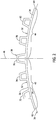
Figure 2 is a representation of a cross-section view of a plurality of fibrous sheets positioned on a tool surface of a tool with the fibrous sheets formed in a configuration of a single structure comprised of a first part joined to a symmetric second part, the configuration of the single structure having a cross-section that is symmetric on opposite sides of a dividing plane through the tool surface and through the single structure. -
Figure 3 is a representation of an elevation view of a first composite part formed from the single structure ofFigure 2 , and a second composite part formed from the single structure ofFigure 2 that is a mirror image of and symmetric to the first composite part. -
Figure 4 is a representation of a perspective view of the first and second composite parts ofFigure 3 . -
Figure 5 is a flow chart of the method of this disclosure. - The construction of an aircraft is, for the most part, symmetric on opposite sides of a dividing plane through the center of the aircraft fuselage. For example, the aircraft has a left hand wing and a symmetric right hand wing on opposite sides of the dividing plane. The aircraft has a left hand stabilizer and a symmetric right hand stabilizer on opposite sides of the dividing plane. These are only a few of the many symmetric exterior components in the construction of an aircraft. Many of the interior components in the construction of an aircraft will also be symmetric on opposite sides of the dividing plane.
- Manufacturing symmetric carbon fiber reinforced composite parts that go into the construction of the left hand side of an aircraft and the right hand side of the aircraft as a single structure, on a single tool surface, and in a single fabrication process can significantly reduce tooling costs, fabrication time, and the factory floor space needed for tooling.
-
Figures 1-4 are representations of the method of manufacturing a first carbon fiber reinforced composite part and a second carbon fiber reinforced composite part from a single carbon fiber reinforced composite structure, where the first composite part and the second composite part are symmetric. - The method of this disclosure initially involves positioning
fibrous material 32 on atool surface 34 of atool 36. Thefibrous material 32 could be some type of bulkfibrous material 32, orfibrous material 32 in a particular configuration. Referring toFigure 1 , the method of this disclosure comprises positioning a plurality of carbon fiber reinforcedcomposite sheets 32, or a plurality of sheets offibrous material 32 on atool surface 34 of atool 36. Thesheets 32 could be dry fibrous sheets. Thesheets 32 could be constructed of pre-preg material or pre-preg fibrous sheets. In the description to follow, the plurality of sheets offibrous material 32 orsheets 32 are dry fiber sheets. Thesheets 32 could be comprised of carbon fiber tapes, carbon fiber fabrics, or a combination of both. Thesheets 32 could be a preform. Thesheets 32 are formed in a configuration of asingle structure 38 comprised of a firstcomposite part 42 orfirst part 42, joined to a symmetric, secondcomposite part 44 orsecond part 44. In the explanation of the method of this disclosure represented inFigures 1-4 , the firstcomposite part 42 is a first portion of an aileron or a left hand portion of an aileron and the secondcomposite part 44 is a second portion of an aileron or a right hand portion of an aileron. It should be understood that the method of this disclosure can be employed in manufacturing other symmetric carbon fiber reinforced composite parts of an aircraft's construction. The method of his disclosure is not limited to only the manufacturing of symmetric carbon fiber reinforced composite ailerons of an aircraft. - Referring to
Figure 2 , thesheets 32 are laid up on thetool surface 34 or formed on thetool surface 34 in a configuration of asingle structure 38. Thesingle structure 38 has a cross section configuration that is symmetric on opposite sides of a dividingplane 48 through thetool surface 34 and through the cross-section of the sheets. Thesingle structure 38 formed by the plurality ofsheets 32 includes abase panel 52. Thebase panel 52 has abottom surface 54 that engages across thetool surface 34 of thetool 36. Thebase panel 52 also has anopposite top surface 56. Thebase panel 52 has a length dimension that extends along the length of the plurality of thesheets 32 configured as thesingle structure 38. Thebase panel 52 also has a width dimension that extends between afirst end edge 62 orleft hand edge 62 of thebase panel 52 as represented inFigure 2 , and an oppositesecond end edge 64 orright hand edge 64 of thebase panel 52 as represented inFigure 2 . - The plurality of
sheets 32 in the configuration of thesingle structure 38 also comprise a plurality of stiffeners formed in the plurality of sheets. The stiffeners as represented inFigure 2 are formed astop hat stiffeners panel top surface 56 from the base panelfirst end edge 62 to the base panelsecond end edge 64. Thetop hat stiffeners sheets 32. Thetop hat stiffeners first end edge 62 and the base panelsecond end edge 64 toward thetop hat stiffener 76 at the center of the plurality ofsheets 32, with the centertop hat stiffener 76 having the largest hollow interior. - With the plurality of
sheets 32 formed as asingle structure 38 on thetool surface 34, a fluidimpervious sheet 84, or avacuum bag 84 is then positioned on thetool surface 34. Thevacuum bag 84 completely covers over the plurality ofsheets 32 configured as thesingle structure 38. The perimeter of thevacuum bag 84 is sealed to thetool surface 34 over the plurality ofsheets 32 and around the plurality of sheets. This forms a sealed volume between thevacuum bag 84 and thetool surface 34 that is occupied by the plurality ofsheets 32. - A pressure differential or
vacuum pressure 86 is applied to the sealed volume between thevacuum bag 84 and thetool surface 34. Thevacuum pressure 86 is represented schematically inFigure 1 . Thevacuum pressure 86 applied to the sealed volume between thevacuum bag 84 and thetool surface 34 draws thevacuum bag 84 down onto the plurality ofsheets 32. - A flow of liquid matrix material or resin 88 is then supplied to the interior volume between the
vacuum bag 84 and thetool surface 34. The flow of liquid resin 88 is represented schematically inFigure 1 . Thevacuum pressure 86 supplied to the interior volume between thevacuum bag 84 and thetool surface 34 infuses the liquid resin 88 into the plurality ofsheets 32 in the configuration of thesingle structure 38. - The plurality of
sheets 32 infused with the liquid resin 88 are then cured on thetool surface 34. Curing the plurality ofsheets 32 and the resin 88 infused into the sheets forms a single curedcomposite structure 92 or single curedstructure 92 comprised of a first cured composite part or first curedpart 94, joined to a symmetric, second cured composite part or second curedpart 96. - The single cured
structure 92 comprised of the first curedpart 94 and the second curedpart 96 is then removed from thetool surface 34. The single curedstructure 92 comprised of the first curedpart 94 joined to the symmetric, second curedpart 96 is then divided along the dividingplane 48. The single curedstructure 92 is divided along the dividingplane 48 by cutting the single cured structure along the dividing plane, or by other equivalent means. This produces the first curedpart 94 and the second curedpart 96 as separate parts, with the first curedpart 94 and the second curedpart 96 being symmetric and mirror images of each other. - With the center
top hat stiffener 76 being divided by the dividingplane 48, cutting through the single curedstructure 92 along the dividingplane 48 and through the centertop hat stiffener 76 produces the first curedpart 94 with a first-fittingattachment surface 102 at an end edge of the first curedpart 94, and the second curedpart 96 with a second-fittingattachment surface 104 at an end edge of the second curedpart 96. The first-fittingattachment surface 102 is represented inFigures 3 and 4 as afirst cavity 102 having a configuration for attachment of afirst fitting 106 in thefirst cavity 102, and the second-fittingattachment surface 104 is represented inFigures 3 and 4 as asecond cavity 104 having a configuration for attachment of asecond fitting 108 in thesecond cavity 104. Thefirst fitting 106 can be used in attaching the first curedpart 94 to a larger structure and thesecond fitting 108 can be used for attaching the second curedpart 96 to the larger structure, with the first curedpart 94 and the second curedpart 96 on opposite sides of the larger structure. For example, the first curedpart 94 could be a left side component part of an aircraft that is assembled to a left side of the aircraft and the second curedpart 96 could be a right side component part of the aircraft that is assembled to the right side of the aircraft. By separating the first curedcomposite part 94 from the second curedcomposite part 96 along the dividingplane 48 through the centertop hat stiffener 76, cavities for attachment of therespective fittings composite parts part 94 and the second curedpart 96 which could cause wasted composite material. - Further, the disclosure comprises embodiments according to the following clauses
- Clause 1. A method of manufacturing a first part and a second part, the method comprising:
- positioning
fibrous material 32 on atool surface 34 of atool 36, thefibrous material 32 having a configuration of asingle structure 38, thesingle structure 38 comprising afirst part 42 and asecond part 44; - curing the
fibrous material 32 producing a single curedstructure 92, the single curedstructure 92 comprising a first curedpart 94 and a second curedpart 96; and, - dividing the single cured
structure 92 into the first curedpart 94 and the second curedpart 96, the first curedpart 94 and the second curedpart 96 being separate parts after the dividing.
- positioning
- Clause 2. The method of Clause 1, further comprising:
- infusing a resin 88 into the
fibrous material 32 on thetool surface 34; and, - curing the
fibrous material 32 and the resin 88 infused into thefibrous material 32 producing the single curedstructure 92.
- infusing a resin 88 into the
- Clause 3. The method of Clause or 2, further comprising:
using a pre-preg material as thefibrous material 32 that is positioned on thetool surface 34 of thetool 36. - Clause 4. The method of any one of Clauses 1-3, further comprising:
positioning thefibrous material 32 on thetool surface 34 of thetool 36, thefibrous material 32 having the configuration of thesingle structure 38, where thefirst part 42 and thesecond part 44 are symmetric on opposite sides of a dividingplane 48 through thetool surface 34. - Clause 5. The method of any one of Clauses 1-4, further comprising:
dividing the single curedstructure 92 into the first curedpart 94 and the second curedpart 96 along a dividingplane 48 through the single curedstructure 92 with the first curedpart 94 and the second curedpart 96 being symmetric on opposite sides of the dividingplane 48. - Clause 6. The method of Clause 5, further comprising:
dividing the single curedstructure 92 into the first curedpart 94 and the second curedpart 96 by cutting through the single curedstructure 92 along the dividingplane 48. - Clause 7. The method of Clause 5 or 6, further comprising:
the first curedpart 94 is a left side component part of an aircraft that is assembled to a left side of an aircraft and the second curedpart 96 is a right side component part of an aircraft that is assembled to a right side of an aircraft. - Clause 8. The method of any one of Clauses 1-4, further comprising:
dividing the single curedstructure 92 into the first curedpart 94 and the second curedpart 96 along a dividingplane 48 through a hollow portion of the single curedstructure 92 producing afirst cavity 102 in the first curedpart 94 and asecond cavity 104 in the second curedpart 96 on opposite sides of the dividingplane 48. - Clause 9. The method of Clause 8, further comprising:
- producing the
first cavity 102 with a configuration for receiving afirst fitting 106 in thefirst cavity 102 for attachment of thefirst fitting 106 to the first curedpart 94; and, - producing the
second cavity 104 with a configuration for receiving asecond fitting 108 in thesecond cavity 104 for attachment of thesecond fitting 108 to the second curedpart 96.
- producing the
- Clause 10. A method of constructing a first part and a second part, the first part and the second part being separate parts, the method comprising:
- positioning sheets of
fibrous material 32 on atool surface 34 of atool 36 with the sheets offibrous material 32 formed in a configuration of asingle structure 38, thesingle structure 38 comprising afirst part 42 and asecond part 44, the sheets offibrous material 32 having a cross-section configuration that is symmetric on opposite sides of a dividingplane 48 through thetool surface 34 and through the cross-section configuration of the sheets offibrous material 32; - curing the sheets of
fibrous material 32 on thetool surface 34 forming a single curedstructure 92 comprising a first curedpart 94 and a second curedpart 96; and, - dividing the single cured
structure 92 along the dividingplane 48 into the first curedpart 94 and the second curedpart 96.
- positioning sheets of
- Clause 11. The method of Clause 10, further comprising:
- infusing a resin 88 into the sheets of
fibrous material 32 positioned on thetool surface 34; and, - curing the sheets of
fibrous material 32 and the resin 88 infused into the sheets offibrous material 32 on thetool surface 34 producing the single curedstructure 92 comprising the first curedpart 94 and the second curedpart 96.
- infusing a resin 88 into the sheets of
- Clause 12. The method of Clause 10 or 11, further comprising:
- using sheets of pre-preg fibrous material as the sheets of
fibrous material 32 positioned on thetool surface 34; and, - curing the sheets of pre-preg fibrous material on the
tool surface 34 forming the single curedstructure 92 comprising the first curedpart 94 and the second curedpart 96.
- using sheets of pre-preg fibrous material as the sheets of
- Clause 13. The method of any one of Clauses 10-12, further comprising:
forming the sheets offibrous material 32 in a configuration where thefirst part 42 and thesecond part 44 are symmetric on opposite sides of the dividingplane 48 through thetool surface 34 and through the cross-section configuration of the sheets offibrous material 32. - Clause 14. The method of any one of Clauses 10-13, further comprising:
dividing the single curedstructure 92 into the first curedpart 94 and the second curedpart 96 along the dividingplane 48 through thetool surface 34 with the first curedpart 94 and the second curedpart 96 being symmetric on opposite sides of the dividingplane 48. - Clause 15. The method of any one of Clauses 10-14, further comprising:
dividing the single curedstructure 92 into the first curedpart 94 and the second cured 96 part along the dividingplane 48 through thetool surface 34 and through a hollow portion of the single curedstructure 92 producing a firstfitting attachment surface 102 on the first curedpart 94 that is configured for attachment of afirst fitting 106 to the firstfitting attachment surface 102 and producing a secondfitting attachment surface 104 on the second curedpart 96 that is configured for attachment of asecond fitting 108 to the secondfitting attachment surface 104. - Clause 16. A method of constructing a first part and a second part, the first part and the second part being separate parts, the method comprising:
- positioning a plurality of sheets of
fibrous material 32 on atool surface 34 of atool 36, the plurality of sheets offibrous material 32 having a configuration of a firstcomposite part 42 joined to a secondcomposite part 44; - curing the plurality of sheets of
fibrous material 32 producing a first curedcomposite part 94 joined to a second curedcomposite part 96; and, - dividing the first cured
composite part 94 joined to the second curedcomposite part 96 after curing, producing the first curedcomposite part 94 and the second curedcomposite part 96 that are separate parts.
- positioning a plurality of sheets of
- Clause 17. The method of Clause 16, further comprising:
- infusing a resin 88 into the plurality of sheets of
fibrous material 32 positioned on thetool surface 34; - curing the plurality of sheets of
fibrous material 32 and the resin 88 infused into the plurality of sheets offibrous material 32 producing the first curedcomposite part 94 joined to the second curedcomposite part 96; and, - dividing the plurality of sheets of
fibrous material 32 and resin 88 after curing into the first curedcomposite part 94 and the second curedcomposite part 96.
- infusing a resin 88 into the plurality of sheets of
- Clause 18. The method of Clause 16 or 17, further comprising:
- using sheets of pre-preg fibrous material as the plurality of sheets of
fibrous material 32 positioned on thetool surface 34; and, - curing the sheets of pre-preg fibrous material.
- using sheets of pre-preg fibrous material as the plurality of sheets of
- Clause 19. The method of any one of Clauses 16-18, further comprising:
dividing the first curedcomposite part 94 joined to the second curedcomposite part 96 along a dividingplane 48 through a hollow portion of the first curedcomposite part 94 joined to the second curedcomposite part 96 producing a firstfitting attachment surface 102 on the first curedcomposite part 94 and a secondfitting attachment surface 104 on the second curedcomposite part 96. - Clause 20. The method of any one of Clauses 16-19, further comprising:
producing the first curedcomposite part 94 and the second curedcomposite part 96 as symmetric parts. - As various modifications could be made in the method of manufacturing a first part and a second part herein described and illustrated without departing from the scope of the method described, it is intended that all matter contained in the foregoing description or shown in the accompanying drawings shall be interpreted as illustrative rather than limiting. Thus, the breadth and scope of the present disclosure should not be limited by any of the above described exemplary embodiments, but should be defined only in accordance with the following claims appended hereto and their equivalents.
Claims (15)
- A method of manufacturing a first cured part (94) and a second cured part (96), the method comprising:positioning fibrous material (32) on a tool surface (34) of a tool (36), the fibrous material (32) having a configuration of a single structure (38), the single structure 38 comprising a first part (42) and a second part (44);curing the fibrous material (32) producing a single cured structure 92, the single cured structure (92) comprising a first cured part (94) and a second cured part 96; and,dividing the single cured structure (92) into the first cured part (94) and the second cured part (96), the first cured part (94) and the second cured part (96) being separate parts after the dividing.
- The method of claim 1, further comprising:infusing a resin (88) into the fibrous material (32) on the tool surface (34); and,curing the fibrous material (32) and the resin (88) infused into the fibrous material 32 producing the single cured structure (92).
- The method of claim 1 or 2, further comprising:
using a pre-preg material as the fibrous material (32) that is positioned on the tool surface (34) of the tool (36). - The method of any one of claims 1-3, further comprising:
positioning the fibrous material (32) on the tool surface (34) of the tool (36), the fibrous material (32) having the configuration of the single structure (38), where the first part (42) and the second part (44) are symmetric on opposite sides of a dividing plane (48) through the tool surface (34). - The method of any one of claims 1-4, further comprising:
dividing the single cured structure (92) into the first cured part (94) and the second cured part (96) along a dividing plane 48 through the single cured structure (92) with the first cured part (94) and the second cured part (96) being symmetric on opposite sides of the dividing plane (48). - The method of claim 5, further comprising:
dividing the single cured structure (92) into the first cured part (94) and the second cured part (96) by cutting through the single cured structure (92) along the dividing plane (48). - The method of any of the preceding claims, wherein:
the first cured part (94) is a left side component part of an aircraft that is assembled to a left side of an aircraft and the second cured part (96) is a right side component part of an aircraft that is assembled to a right side of an aircraft. - The method of any one of claims 1-4, further comprising:
dividing the single cured structure (92) into the first cured part (94) and the second cured part (96) along a dividing plane (48) through a hollow portion of the single cured structure (92) producing a first cavity (102) in the first cured part (94) and a second cavity (104) in the second cured part (96) on opposite sides of the dividing plane (48). - The method of claim 8, further comprising:producing the first cavity (102) with a configuration for receiving a first fitting (106) in the first cavity (102) for attachment of the first fitting (106) to the first cured part (94); and,producing the second cavity (104) with a configuration for receiving a second fitting (108) in the second cavity (104) for attachment of the second fitting (108) to the second cured part (96).
- A method of manufacturing a first cured composite part (94) and a second cured composite part (96), the first part and the second part being separate parts, the method comprising:positioning a plurality of sheets of fibrous material (32) on a tool surface (34) of a tool (36), the plurality of sheets of fibrous material 32 having a configuration of a first composite part (42) joined to a second composite part (44);curing the plurality of sheets of fibrous material (32) producing a first cured composite part (94) joined to a second cured composite part (96); and,dividing the first cured composite part (94) joined to the second cured composite part (96) after curing, producing the first cured composite part (94) and the second cured composite part (96) that are separate parts.
- The method of claim 10, further comprising:infusing a resin (88) into the plurality of sheets of fibrous material 32 positioned on the tool surface (34);curing the plurality of sheets of fibrous material (32) and the resin (88) infused into the plurality of sheets of fibrous material (32) producing the first cured composite part (94) joined to the second cured composite part (96); and,dividing the plurality of sheets of fibrous material (32) and resin (88) after curing into the first cured composite part (94) and the second cured composite part (96).
- The method of claim 10 or 11, further comprising:using sheets of pre-preg fibrous material as the plurality of sheets of fibrous material (32) positioned on the tool surface (34); and,curing the sheets of pre-preg fibrous material.
- The method of any one of claims 10-12, further comprising:
dividing the first cured composite part (94) joined to the second cured composite part (96) along a dividing plane (48) through a hollow portion of the first cured composite part (94) joined to the second cured composite part (96) producing a first fitting attachment surface (102) on the first cured composite part (94) and a second fitting attachment surface (104) on the second cured composite part (96). - The method of any one of claims 10-13, further comprising:
producing the first cured composite part (94) and the second cured composite part (96) as symmetric parts. - The method of any one of claims 10-14, wherein the plurality of sheets of fibrous material (32) formed in a configuration of a single structure (38), the single structure (38) comprising the first composite part (42) and the second composite part (44), the sheets of fibrous material (32) having a cross-section configuration that is symmetric on opposite sides of a dividing plane (48) through the tool surface (34) and through the cross-section configuration of the sheets of fibrous material (32).
Applications Claiming Priority (1)
| Application Number | Priority Date | Filing Date | Title |
|---|---|---|---|
| US16/183,485 US11383463B2 (en) | 2018-11-07 | 2018-11-07 | Method of manufacturing a first cured part and a second cured part |
Publications (2)
| Publication Number | Publication Date |
|---|---|
| EP3650209A1 true EP3650209A1 (en) | 2020-05-13 |
| EP3650209B1 EP3650209B1 (en) | 2023-01-11 |
Family
ID=68342514
Family Applications (1)
| Application Number | Title | Priority Date | Filing Date |
|---|---|---|---|
| EP19204624.1A Active EP3650209B1 (en) | 2018-11-07 | 2019-10-22 | Method of manufacturing a first cured part and a second cured part |
Country Status (4)
| Country | Link |
|---|---|
| US (1) | US11383463B2 (en) |
| EP (1) | EP3650209B1 (en) |
| JP (1) | JP7526561B2 (en) |
| AU (1) | AU2019261763B2 (en) |
Cited By (1)
| Publication number | Priority date | Publication date | Assignee | Title |
|---|---|---|---|---|
| WO2022033059A1 (en) * | 2020-08-11 | 2022-02-17 | 上纬新材料科技股份有限公司 | Male die tooling for manufacturing wind turbine blade prepreg main beam |
Citations (4)
| Publication number | Priority date | Publication date | Assignee | Title |
|---|---|---|---|---|
| US4118814A (en) * | 1975-11-17 | 1978-10-10 | Gerald Herbert Holtom | Manufacture of boat hulls and other hollow articles |
| US4401495A (en) * | 1981-09-28 | 1983-08-30 | The Boeing Company | Method of winding composite panels |
| FR2760397A1 (en) * | 1997-03-06 | 1998-09-11 | Jean Alphonse David | Railway tanker body structural assembly |
| US20130020438A1 (en) * | 2011-07-18 | 2013-01-24 | The Boeing Company | Flexible Truss Frame and Method of Making the Same |
Family Cites Families (3)
| Publication number | Priority date | Publication date | Assignee | Title |
|---|---|---|---|---|
| EP0069539A1 (en) | 1981-07-04 | 1983-01-12 | The British Petroleum Company p.l.c. | Structural components |
| DE102011007235A1 (en) * | 2011-04-12 | 2012-10-18 | Airbus Operations Gmbh | Method and device for producing a fiber composite component and fiber composite component |
| HK1250693A1 (en) * | 2015-04-10 | 2019-01-11 | Leonardo S.P.A. | Method for manufacturing stiffened panels of composite material by means of co-curing |
-
2018
- 2018-11-07 US US16/183,485 patent/US11383463B2/en active Active
-
2019
- 2019-10-22 EP EP19204624.1A patent/EP3650209B1/en active Active
- 2019-11-05 JP JP2019200391A patent/JP7526561B2/en active Active
- 2019-11-07 AU AU2019261763A patent/AU2019261763B2/en active Active
Patent Citations (4)
| Publication number | Priority date | Publication date | Assignee | Title |
|---|---|---|---|---|
| US4118814A (en) * | 1975-11-17 | 1978-10-10 | Gerald Herbert Holtom | Manufacture of boat hulls and other hollow articles |
| US4401495A (en) * | 1981-09-28 | 1983-08-30 | The Boeing Company | Method of winding composite panels |
| FR2760397A1 (en) * | 1997-03-06 | 1998-09-11 | Jean Alphonse David | Railway tanker body structural assembly |
| US20130020438A1 (en) * | 2011-07-18 | 2013-01-24 | The Boeing Company | Flexible Truss Frame and Method of Making the Same |
Cited By (1)
| Publication number | Priority date | Publication date | Assignee | Title |
|---|---|---|---|---|
| WO2022033059A1 (en) * | 2020-08-11 | 2022-02-17 | 上纬新材料科技股份有限公司 | Male die tooling for manufacturing wind turbine blade prepreg main beam |
Also Published As
| Publication number | Publication date |
|---|---|
| US11383463B2 (en) | 2022-07-12 |
| AU2019261763A1 (en) | 2020-05-21 |
| JP7526561B2 (en) | 2024-08-01 |
| JP2020097227A (en) | 2020-06-25 |
| US20200139650A1 (en) | 2020-05-07 |
| AU2019261763B2 (en) | 2025-01-02 |
| EP3650209B1 (en) | 2023-01-11 |
Similar Documents
| Publication | Publication Date | Title |
|---|---|---|
| EP3521002B1 (en) | Composite material structure and method for manufacturing composite material structure | |
| CN104743095B (en) | Highly integrated perfusion case and manufacturing method made of composite material | |
| EP0845410B1 (en) | Leading edge for an aerodynamic surface and fabrication method therefor | |
| EP2364248B1 (en) | Moulded body for producing a fibre composite component | |
| EP0061567B1 (en) | Aerodynamic propeller blade and manufacturing process | |
| DE102007003275B4 (en) | Shell element as part of an aircraft fuselage | |
| EP2585282B1 (en) | Mold for producing fiber-reinforced components | |
| EP2301840A2 (en) | Integrated aircraft structure in composite material | |
| US20130115429A1 (en) | Composite structure and method of forming same | |
| EP2905220A1 (en) | Laminated I-blade stringer | |
| EP2159038A1 (en) | Method and tool for producing composite-material structures | |
| EP2292415B1 (en) | Method for producing a component with at least one hollow profile and hollow body for carrying out this method | |
| EP3159259B1 (en) | Leading edge with laminar flow control and manufacturing method thereof | |
| EP3533705B1 (en) | Stringer transition through a common base charge | |
| GB2575103A (en) | Method of manufacturing duct stringer | |
| EP3365159B1 (en) | Method and apparatus for forming a composite skin-stiffener assembly | |
| EP3205491B1 (en) | Method for manufacturing a stiffened panel made from composite material | |
| EP3650209A1 (en) | Method of manufacturing a first cured part and a second cured part | |
| AT517198B1 (en) | Control surface element for an airplane | |
| HUE031521T2 (en) | Coupling system intended for use between cladding and structural elements supporting same | |
| US20150059967A1 (en) | Method for manufacturing a composite skin forming a non-strippable shroud | |
| DE102017128496B4 (en) | Method for manufacturing a structural section of a vehicle | |
| IT202300023190A1 (en) | METHOD FOR THE MANUFACTURE OF A COMPOSITE-REINFORCED STRUCTURAL COMPONENT AND STRUCTURAL COMPONENT | |
| DE102011079928A1 (en) | Device for producing an adhesive component with fiber-reinforced plastics and method | |
| EP3415301A1 (en) | Composite panel sandwich structures with integrated joints |
Legal Events
| Date | Code | Title | Description |
|---|---|---|---|
| PUAI | Public reference made under article 153(3) epc to a published international application that has entered the european phase |
Free format text: ORIGINAL CODE: 0009012 |
|
| STAA | Information on the status of an ep patent application or granted ep patent |
Free format text: STATUS: THE APPLICATION HAS BEEN PUBLISHED |
|
| AK | Designated contracting states |
Kind code of ref document: A1 Designated state(s): AL AT BE BG CH CY CZ DE DK EE ES FI FR GB GR HR HU IE IS IT LI LT LU LV MC MK MT NL NO PL PT RO RS SE SI SK SM TR |
|
| AX | Request for extension of the european patent |
Extension state: BA ME |
|
| STAA | Information on the status of an ep patent application or granted ep patent |
Free format text: STATUS: REQUEST FOR EXAMINATION WAS MADE |
|
| 17P | Request for examination filed |
Effective date: 20201016 |
|
| RBV | Designated contracting states (corrected) |
Designated state(s): AL AT BE BG CH CY CZ DE DK EE ES FI FR GB GR HR HU IE IS IT LI LT LU LV MC MK MT NL NO PL PT RO RS SE SI SK SM TR |
|
| STAA | Information on the status of an ep patent application or granted ep patent |
Free format text: STATUS: EXAMINATION IS IN PROGRESS |
|
| 17Q | First examination report despatched |
Effective date: 20210707 |
|
| GRAP | Despatch of communication of intention to grant a patent |
Free format text: ORIGINAL CODE: EPIDOSNIGR1 |
|
| STAA | Information on the status of an ep patent application or granted ep patent |
Free format text: STATUS: GRANT OF PATENT IS INTENDED |
|
| GRAS | Grant fee paid |
Free format text: ORIGINAL CODE: EPIDOSNIGR3 |
|
| GRAA | (expected) grant |
Free format text: ORIGINAL CODE: 0009210 |
|
| STAA | Information on the status of an ep patent application or granted ep patent |
Free format text: STATUS: THE PATENT HAS BEEN GRANTED |
|
| INTG | Intention to grant announced |
Effective date: 20221116 |
|
| AK | Designated contracting states |
Kind code of ref document: B1 Designated state(s): AL AT BE BG CH CY CZ DE DK EE ES FI FR GB GR HR HU IE IS IT LI LT LU LV MC MK MT NL NO PL PT RO RS SE SI SK SM TR |
|
| REG | Reference to a national code |
Ref country code: GB Ref legal event code: FG4D |
|
| REG | Reference to a national code |
Ref country code: CH Ref legal event code: EP |
|
| REG | Reference to a national code |
Ref country code: DE Ref legal event code: R096 Ref document number: 602019024237 Country of ref document: DE |
|
| REG | Reference to a national code |
Ref country code: IE Ref legal event code: FG4D |
|
| REG | Reference to a national code |
Ref country code: AT Ref legal event code: REF Ref document number: 1543170 Country of ref document: AT Kind code of ref document: T Effective date: 20230215 |
|
| RAP4 | Party data changed (patent owner data changed or rights of a patent transferred) |
Owner name: THE BOEING COMPANY |
|
| REG | Reference to a national code |
Ref country code: LT Ref legal event code: MG9D |
|
| REG | Reference to a national code |
Ref country code: NL Ref legal event code: MP Effective date: 20230111 |
|
| REG | Reference to a national code |
Ref country code: AT Ref legal event code: MK05 Ref document number: 1543170 Country of ref document: AT Kind code of ref document: T Effective date: 20230111 |
|
| P01 | Opt-out of the competence of the unified patent court (upc) registered |
Effective date: 20230516 |
|
| PG25 | Lapsed in a contracting state [announced via postgrant information from national office to epo] |
Ref country code: NL Free format text: LAPSE BECAUSE OF FAILURE TO SUBMIT A TRANSLATION OF THE DESCRIPTION OR TO PAY THE FEE WITHIN THE PRESCRIBED TIME-LIMIT Effective date: 20230111 |
|
| PG25 | Lapsed in a contracting state [announced via postgrant information from national office to epo] |
Ref country code: RS Free format text: LAPSE BECAUSE OF FAILURE TO SUBMIT A TRANSLATION OF THE DESCRIPTION OR TO PAY THE FEE WITHIN THE PRESCRIBED TIME-LIMIT Effective date: 20230111 Ref country code: PT Free format text: LAPSE BECAUSE OF FAILURE TO SUBMIT A TRANSLATION OF THE DESCRIPTION OR TO PAY THE FEE WITHIN THE PRESCRIBED TIME-LIMIT Effective date: 20230511 Ref country code: NO Free format text: LAPSE BECAUSE OF FAILURE TO SUBMIT A TRANSLATION OF THE DESCRIPTION OR TO PAY THE FEE WITHIN THE PRESCRIBED TIME-LIMIT Effective date: 20230411 Ref country code: LV Free format text: LAPSE BECAUSE OF FAILURE TO SUBMIT A TRANSLATION OF THE DESCRIPTION OR TO PAY THE FEE WITHIN THE PRESCRIBED TIME-LIMIT Effective date: 20230111 Ref country code: LT Free format text: LAPSE BECAUSE OF FAILURE TO SUBMIT A TRANSLATION OF THE DESCRIPTION OR TO PAY THE FEE WITHIN THE PRESCRIBED TIME-LIMIT Effective date: 20230111 Ref country code: HR Free format text: LAPSE BECAUSE OF FAILURE TO SUBMIT A TRANSLATION OF THE DESCRIPTION OR TO PAY THE FEE WITHIN THE PRESCRIBED TIME-LIMIT Effective date: 20230111 Ref country code: ES Free format text: LAPSE BECAUSE OF FAILURE TO SUBMIT A TRANSLATION OF THE DESCRIPTION OR TO PAY THE FEE WITHIN THE PRESCRIBED TIME-LIMIT Effective date: 20230111 Ref country code: AT Free format text: LAPSE BECAUSE OF FAILURE TO SUBMIT A TRANSLATION OF THE DESCRIPTION OR TO PAY THE FEE WITHIN THE PRESCRIBED TIME-LIMIT Effective date: 20230111 |
|
| PG25 | Lapsed in a contracting state [announced via postgrant information from national office to epo] |
Ref country code: SE Free format text: LAPSE BECAUSE OF FAILURE TO SUBMIT A TRANSLATION OF THE DESCRIPTION OR TO PAY THE FEE WITHIN THE PRESCRIBED TIME-LIMIT Effective date: 20230111 Ref country code: PL Free format text: LAPSE BECAUSE OF FAILURE TO SUBMIT A TRANSLATION OF THE DESCRIPTION OR TO PAY THE FEE WITHIN THE PRESCRIBED TIME-LIMIT Effective date: 20230111 Ref country code: IS Free format text: LAPSE BECAUSE OF FAILURE TO SUBMIT A TRANSLATION OF THE DESCRIPTION OR TO PAY THE FEE WITHIN THE PRESCRIBED TIME-LIMIT Effective date: 20230511 Ref country code: GR Free format text: LAPSE BECAUSE OF FAILURE TO SUBMIT A TRANSLATION OF THE DESCRIPTION OR TO PAY THE FEE WITHIN THE PRESCRIBED TIME-LIMIT Effective date: 20230412 Ref country code: FI Free format text: LAPSE BECAUSE OF FAILURE TO SUBMIT A TRANSLATION OF THE DESCRIPTION OR TO PAY THE FEE WITHIN THE PRESCRIBED TIME-LIMIT Effective date: 20230111 |
|
| REG | Reference to a national code |
Ref country code: DE Ref legal event code: R097 Ref document number: 602019024237 Country of ref document: DE |
|
| PG25 | Lapsed in a contracting state [announced via postgrant information from national office to epo] |
Ref country code: SM Free format text: LAPSE BECAUSE OF FAILURE TO SUBMIT A TRANSLATION OF THE DESCRIPTION OR TO PAY THE FEE WITHIN THE PRESCRIBED TIME-LIMIT Effective date: 20230111 Ref country code: RO Free format text: LAPSE BECAUSE OF FAILURE TO SUBMIT A TRANSLATION OF THE DESCRIPTION OR TO PAY THE FEE WITHIN THE PRESCRIBED TIME-LIMIT Effective date: 20230111 Ref country code: EE Free format text: LAPSE BECAUSE OF FAILURE TO SUBMIT A TRANSLATION OF THE DESCRIPTION OR TO PAY THE FEE WITHIN THE PRESCRIBED TIME-LIMIT Effective date: 20230111 Ref country code: DK Free format text: LAPSE BECAUSE OF FAILURE TO SUBMIT A TRANSLATION OF THE DESCRIPTION OR TO PAY THE FEE WITHIN THE PRESCRIBED TIME-LIMIT Effective date: 20230111 Ref country code: CZ Free format text: LAPSE BECAUSE OF FAILURE TO SUBMIT A TRANSLATION OF THE DESCRIPTION OR TO PAY THE FEE WITHIN THE PRESCRIBED TIME-LIMIT Effective date: 20230111 |
|
| PLBE | No opposition filed within time limit |
Free format text: ORIGINAL CODE: 0009261 |
|
| STAA | Information on the status of an ep patent application or granted ep patent |
Free format text: STATUS: NO OPPOSITION FILED WITHIN TIME LIMIT |
|
| PG25 | Lapsed in a contracting state [announced via postgrant information from national office to epo] |
Ref country code: SK Free format text: LAPSE BECAUSE OF FAILURE TO SUBMIT A TRANSLATION OF THE DESCRIPTION OR TO PAY THE FEE WITHIN THE PRESCRIBED TIME-LIMIT Effective date: 20230111 |
|
| 26N | No opposition filed |
Effective date: 20231012 |
|
| PG25 | Lapsed in a contracting state [announced via postgrant information from national office to epo] |
Ref country code: SI Free format text: LAPSE BECAUSE OF FAILURE TO SUBMIT A TRANSLATION OF THE DESCRIPTION OR TO PAY THE FEE WITHIN THE PRESCRIBED TIME-LIMIT Effective date: 20230111 |
|
| PG25 | Lapsed in a contracting state [announced via postgrant information from national office to epo] |
Ref country code: IT Free format text: LAPSE BECAUSE OF FAILURE TO SUBMIT A TRANSLATION OF THE DESCRIPTION OR TO PAY THE FEE WITHIN THE PRESCRIBED TIME-LIMIT Effective date: 20230111 Ref country code: MC Free format text: LAPSE BECAUSE OF FAILURE TO SUBMIT A TRANSLATION OF THE DESCRIPTION OR TO PAY THE FEE WITHIN THE PRESCRIBED TIME-LIMIT Effective date: 20230111 |
|
| REG | Reference to a national code |
Ref country code: CH Ref legal event code: PL |
|
| REG | Reference to a national code |
Ref country code: BE Ref legal event code: MM Effective date: 20231031 |
|
| PG25 | Lapsed in a contracting state [announced via postgrant information from national office to epo] |
Ref country code: LU Free format text: LAPSE BECAUSE OF NON-PAYMENT OF DUE FEES Effective date: 20231022 |
|
| PG25 | Lapsed in a contracting state [announced via postgrant information from national office to epo] |
Ref country code: LU Free format text: LAPSE BECAUSE OF NON-PAYMENT OF DUE FEES Effective date: 20231022 |
|
| PG25 | Lapsed in a contracting state [announced via postgrant information from national office to epo] |
Ref country code: CH Free format text: LAPSE BECAUSE OF NON-PAYMENT OF DUE FEES Effective date: 20231031 |
|
| PG25 | Lapsed in a contracting state [announced via postgrant information from national office to epo] |
Ref country code: CH Free format text: LAPSE BECAUSE OF NON-PAYMENT OF DUE FEES Effective date: 20231031 |
|
| PG25 | Lapsed in a contracting state [announced via postgrant information from national office to epo] |
Ref country code: BE Free format text: LAPSE BECAUSE OF NON-PAYMENT OF DUE FEES Effective date: 20231031 |
|
| PG25 | Lapsed in a contracting state [announced via postgrant information from national office to epo] |
Ref country code: IE Free format text: LAPSE BECAUSE OF NON-PAYMENT OF DUE FEES Effective date: 20231022 |
|
| PG25 | Lapsed in a contracting state [announced via postgrant information from national office to epo] |
Ref country code: IE Free format text: LAPSE BECAUSE OF NON-PAYMENT OF DUE FEES Effective date: 20231022 |
|
| PG25 | Lapsed in a contracting state [announced via postgrant information from national office to epo] |
Ref country code: BG Free format text: LAPSE BECAUSE OF FAILURE TO SUBMIT A TRANSLATION OF THE DESCRIPTION OR TO PAY THE FEE WITHIN THE PRESCRIBED TIME-LIMIT Effective date: 20230111 |
|
| PG25 | Lapsed in a contracting state [announced via postgrant information from national office to epo] |
Ref country code: BG Free format text: LAPSE BECAUSE OF FAILURE TO SUBMIT A TRANSLATION OF THE DESCRIPTION OR TO PAY THE FEE WITHIN THE PRESCRIBED TIME-LIMIT Effective date: 20230111 |
|
| PG25 | Lapsed in a contracting state [announced via postgrant information from national office to epo] |
Ref country code: CY Free format text: LAPSE BECAUSE OF FAILURE TO SUBMIT A TRANSLATION OF THE DESCRIPTION OR TO PAY THE FEE WITHIN THE PRESCRIBED TIME-LIMIT; INVALID AB INITIO Effective date: 20191022 |
|
| PG25 | Lapsed in a contracting state [announced via postgrant information from national office to epo] |
Ref country code: HU Free format text: LAPSE BECAUSE OF FAILURE TO SUBMIT A TRANSLATION OF THE DESCRIPTION OR TO PAY THE FEE WITHIN THE PRESCRIBED TIME-LIMIT; INVALID AB INITIO Effective date: 20191022 |
|
| PG25 | Lapsed in a contracting state [announced via postgrant information from national office to epo] |
Ref country code: TR Free format text: LAPSE BECAUSE OF FAILURE TO SUBMIT A TRANSLATION OF THE DESCRIPTION OR TO PAY THE FEE WITHIN THE PRESCRIBED TIME-LIMIT Effective date: 20230111 |
|
| PGFP | Annual fee paid to national office [announced via postgrant information from national office to epo] |
Ref country code: DE Payment date: 20251029 Year of fee payment: 7 |
|
| PGFP | Annual fee paid to national office [announced via postgrant information from national office to epo] |
Ref country code: GB Payment date: 20251027 Year of fee payment: 7 |
|
| PGFP | Annual fee paid to national office [announced via postgrant information from national office to epo] |
Ref country code: FR Payment date: 20251027 Year of fee payment: 7 |