EP3650155A1 - Orbitalschweissvorrichtung mit verbesserter restsauerstoffmessung - Google Patents
Orbitalschweissvorrichtung mit verbesserter restsauerstoffmessung Download PDFInfo
- Publication number
- EP3650155A1 EP3650155A1 EP18205526.9A EP18205526A EP3650155A1 EP 3650155 A1 EP3650155 A1 EP 3650155A1 EP 18205526 A EP18205526 A EP 18205526A EP 3650155 A1 EP3650155 A1 EP 3650155A1
- Authority
- EP
- European Patent Office
- Prior art keywords
- welding
- orbital
- orbital welding
- chamber
- oxygen sensor
- Prior art date
- Legal status (The legal status is an assumption and is not a legal conclusion. Google has not performed a legal analysis and makes no representation as to the accuracy of the status listed.)
- Granted
Links
Images


Classifications
-
- B—PERFORMING OPERATIONS; TRANSPORTING
- B23—MACHINE TOOLS; METAL-WORKING NOT OTHERWISE PROVIDED FOR
- B23K—SOLDERING OR UNSOLDERING; WELDING; CLADDING OR PLATING BY SOLDERING OR WELDING; CUTTING BY APPLYING HEAT LOCALLY, e.g. FLAME CUTTING; WORKING BY LASER BEAM
- B23K9/00—Arc welding or cutting
- B23K9/02—Seam welding; Backing means; Inserts
- B23K9/028—Seam welding; Backing means; Inserts for curved planar seams
- B23K9/0282—Seam welding; Backing means; Inserts for curved planar seams for welding tube sections
- B23K9/0286—Seam welding; Backing means; Inserts for curved planar seams for welding tube sections with an electrode moving around the fixed tube during the welding operation
-
- B—PERFORMING OPERATIONS; TRANSPORTING
- B23—MACHINE TOOLS; METAL-WORKING NOT OTHERWISE PROVIDED FOR
- B23K—SOLDERING OR UNSOLDERING; WELDING; CLADDING OR PLATING BY SOLDERING OR WELDING; CUTTING BY APPLYING HEAT LOCALLY, e.g. FLAME CUTTING; WORKING BY LASER BEAM
- B23K37/00—Auxiliary devices or processes, not specially adapted for a procedure covered by only one of the other main groups of this subclass
- B23K37/02—Carriages for supporting the welding or cutting element
- B23K37/0211—Carriages for supporting the welding or cutting element travelling on a guide member, e.g. rail, track
- B23K37/0217—Carriages for supporting the welding or cutting element travelling on a guide member, e.g. rail, track the guide member being fixed to the workpiece
-
- B—PERFORMING OPERATIONS; TRANSPORTING
- B23—MACHINE TOOLS; METAL-WORKING NOT OTHERWISE PROVIDED FOR
- B23K—SOLDERING OR UNSOLDERING; WELDING; CLADDING OR PLATING BY SOLDERING OR WELDING; CUTTING BY APPLYING HEAT LOCALLY, e.g. FLAME CUTTING; WORKING BY LASER BEAM
- B23K37/00—Auxiliary devices or processes, not specially adapted for a procedure covered by only one of the other main groups of this subclass
- B23K37/02—Carriages for supporting the welding or cutting element
- B23K37/027—Carriages for supporting the welding or cutting element for making circular cuts or welds
-
- B—PERFORMING OPERATIONS; TRANSPORTING
- B23—MACHINE TOOLS; METAL-WORKING NOT OTHERWISE PROVIDED FOR
- B23K—SOLDERING OR UNSOLDERING; WELDING; CLADDING OR PLATING BY SOLDERING OR WELDING; CUTTING BY APPLYING HEAT LOCALLY, e.g. FLAME CUTTING; WORKING BY LASER BEAM
- B23K37/00—Auxiliary devices or processes, not specially adapted for a procedure covered by only one of the other main groups of this subclass
- B23K37/02—Carriages for supporting the welding or cutting element
- B23K37/0276—Carriages for supporting the welding or cutting element for working on or in tubes
-
- B—PERFORMING OPERATIONS; TRANSPORTING
- B23—MACHINE TOOLS; METAL-WORKING NOT OTHERWISE PROVIDED FOR
- B23K—SOLDERING OR UNSOLDERING; WELDING; CLADDING OR PLATING BY SOLDERING OR WELDING; CUTTING BY APPLYING HEAT LOCALLY, e.g. FLAME CUTTING; WORKING BY LASER BEAM
- B23K9/00—Arc welding or cutting
- B23K9/095—Monitoring or automatic control of welding parameters
- B23K9/0956—Monitoring or automatic control of welding parameters using sensing means, e.g. optical
-
- B—PERFORMING OPERATIONS; TRANSPORTING
- B23—MACHINE TOOLS; METAL-WORKING NOT OTHERWISE PROVIDED FOR
- B23K—SOLDERING OR UNSOLDERING; WELDING; CLADDING OR PLATING BY SOLDERING OR WELDING; CUTTING BY APPLYING HEAT LOCALLY, e.g. FLAME CUTTING; WORKING BY LASER BEAM
- B23K9/00—Arc welding or cutting
- B23K9/16—Arc welding or cutting making use of shielding gas
-
- B—PERFORMING OPERATIONS; TRANSPORTING
- B23—MACHINE TOOLS; METAL-WORKING NOT OTHERWISE PROVIDED FOR
- B23K—SOLDERING OR UNSOLDERING; WELDING; CLADDING OR PLATING BY SOLDERING OR WELDING; CUTTING BY APPLYING HEAT LOCALLY, e.g. FLAME CUTTING; WORKING BY LASER BEAM
- B23K9/00—Arc welding or cutting
- B23K9/32—Accessories
- B23K9/325—Devices for supplying or evacuating shielding gas
- B23K9/326—Purge gas rings, i.e. devices for supplying or evacuating shielding gas inside of hollow or tubular articles, e.g. pipes, vessels
-
- B—PERFORMING OPERATIONS; TRANSPORTING
- B23—MACHINE TOOLS; METAL-WORKING NOT OTHERWISE PROVIDED FOR
- B23K—SOLDERING OR UNSOLDERING; WELDING; CLADDING OR PLATING BY SOLDERING OR WELDING; CUTTING BY APPLYING HEAT LOCALLY, e.g. FLAME CUTTING; WORKING BY LASER BEAM
- B23K2101/00—Articles made by soldering, welding or cutting
- B23K2101/04—Tubular or hollow articles
- B23K2101/06—Tubes
Definitions
- the invention relates generally to orbital welding devices with residual oxygen measurement.
- the state of the art WO 2014/130374 shows an orbital welding device, in which an optical oxygen sensor is arranged inside the housing, which forms a chamber for protective gas, or as an alternative outside this housing, with an additional suction device being connected to the chamber.
- an orbital welding device having a welding current source in a welding current source housing and an orbital welding head separate from the welding current source housing and connected to the welding current source by means of a cable, the orbital welding head being a pipe holder and a welding electrode holder rotatably mounted relative to the pipe holder for holding the Welding electrode, wherein the orbital welding device has an electric motor, preferably controlled by a motor controller of the orbital welding device, which is set up to drive the welding electrode holder and thus rotate it relative to the pipe holder, the orbital welding head or the cable or a gas line to the orbital welding head or the orbital welding device has an optical oxygen sensor in or on the welding current source housing u nd the orbital welding head has a chamber for protective gas, which is set up to surround a welding electrode of the orbital welding head during a welding process and essentially to close off from the outside, the optical oxygen sensor being set up, an oxygen concentration in a measuring range in the Chamber to measure the oxygen
- the oxygen sensor is arranged outside the chamber and thus protected on or in the orbital welding head or cable or on or in the welding current source housing, and at the same time a quasi-delay-free measurement without a suction device is made possible.
- the area near the orbital welding head is preferred.
- the optical coupling is preferably carried out via one or more light guides which are guided along the cable or the gas line, at least partially connected, preferably inserted in the outermost or an inner cable sheath, preferably glass fibers.
- the arrangement is preferably an attachment such that the oxygen sensor remains or can remain there for the intended oxygen measurements.
- the optical coupling is also preferably integrated, so that no loose light guides can be handled separately.
- the cable preferably has a minimum length of 1 m, preferably 2 m, particularly preferably 5 m.
- the pipe holder is preferably a clamp-like clamp.
- the welding power source is preferably stationary, while the orbital welding head is manually portable.
- essentially closed means that there may also be gaps or small openings, which, however, are so small that they do not create a protective gas atmosphere (preferably with less than 20 ppm, particularly preferably less than 10 ppm residual oxygen) in the chamber oppose.
- the chamber is preferably designed in such a way that the pipe pieces which are to be welded to one another are enclosed by the chamber at the ends to be connected.
- the chamber preferably has an entrance, e.g. with a hose connection for protective gas, with which the chamber can thus be filled. The previously existing air is then forced out of the chamber through the aforementioned small gaps or openings.
- the chamber can also have a dedicated gas outlet.
- the chamber is preferably designed such that the welding electrode in the chamber can be rotated around the pipe pieces to be welded.
- the light sensitive surface of the oxygen sensor is preferably the surface where a light is converted into an electrical signal using the photoelectric effect, e.g. the light sensitive area of a photodiode.
- the orbital welding head preferably has a housing which adjoins the chamber and which e.g. for a user forms a handle or a housing for operating or switching elements and / or the motor, and the oxygen sensor is arranged in or on the housing.
- the optical coupling is at least partially formed by an opening in a wall of the chamber.
- the oxygen sensor is preferably arranged behind the wall of the chamber and the light-sensitive surface of the oxygen sensor is directed towards the opening.
- One or more mirrors are particularly preferably arranged in the beam path between the opening and the light-sensitive surface of the oxygen sensor, so that the beam path can run around corners, as a result of which the position of the oxygen sensor can be selected more flexibly.
- the opening is preferably closed by a light guide element, e.g. a piece of glass.
- the optical coupling is at least partially formed by a light guide element.
- the position of the oxygen sensor can be selected even more flexibly.
- the light guide element is at least partially formed by a glass fiber.
- the position of the oxygen sensor can be selected even more flexibly with a very small space requirement for the light guide element.
- the glass fiber is preferably directed toward the measuring region, preferably through the opening.
- the oxygen sensor preferably a light-sensitive surface, for example a photodiode, of the Oxygen sensor, is optically coupled to a further measuring range in the chamber via a further optical coupling.
- the further measuring area can have overlap areas with the first measuring area, but is altogether different.
- the optical coupling is preferably at least partially formed by a further opening in a wall of the chamber.
- the optical coupling is preferably at least partially formed by a further light guide element.
- the further light-guiding element is preferably at least partially formed by a further glass fiber, which is preferably, preferably through the further opening, directed towards the further measuring area.
- the orbital welding head has at least one further oxygen sensor, the further oxygen sensor, preferably a light-sensitive surface, e.g. a photodiode, the oxygen sensor, is optically coupled to a further measuring range in the chamber via a further optical coupling.
- the further oxygen sensor preferably a light-sensitive surface, e.g. a photodiode, the oxygen sensor
- the further measuring area can have overlap areas with the first measuring area, but is altogether different.
- the optical coupling is preferably at least partially formed by a further opening in a wall of the chamber.
- the optical coupling is preferably at least partially formed by a further light guide element.
- the further light-guiding element is preferably at least partially formed by a further glass fiber, which is preferably, preferably through the further opening, directed towards the further measuring area.
- the orbital welding device preferably the orbital welding head, has an electrical control device which is set up to start a welding process as soon as the oxygen concentration in one or more of the measuring ranges has fallen below a predetermined threshold value.
- the welding process is started after a predetermined time after the protective gas has been introduced into the chamber, the predetermined time being so generously dimensioned that the oxygen concentration is with certainty low enough that it happens that it is unnecessary long waited.
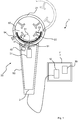
- the orbital welding device 1 has a welding current source 10 in a welding current source housing 11 and an orbital welding head 20 separate from the welding current source housing 11 and connected to the welding current source 10 by means of a cable 2, the orbital welding head 20 having a tube holder 21 and one opposite the tube holder 21 has rotatably mounted welding electrode holder 22 for holding the welding electrode 23, the orbital welding device 1 having an electric motor 31, here controlled by a motor controller 30 of the orbital welding device 1, which is set up to drive the welding electrode holder 22 and thus to rotate it relative to the pipe holder 21, being the Orbital welding head 20 has an optical oxygen sensor 40 and a chamber 50 for protective gas, which is set up to surround a welding electrode 23 of the orbital welding head 20 during a welding process and essentially to close it off from the outside, the optical oxygen sensor 40 being set up to have an oxygen concentration in one To measure the measuring range 51 in the chamber 50, the oxygen sensor 40 being arranged outside the chamber 50 and the oxygen sensor 40,
- the pipe bracket 21 can be closed by a folding mechanism.
- the cable 2 has a minimum length of 1m, here 2m.
- the chamber 50 is configured here in such a way that the pipe sections which are to be welded to one another are enclosed by the chamber 50 at the ends to be connected.
- the chamber 50 here has an inlet 54, for example with a hose connection, for protective gas, with which the chamber can thus be filled.
- the chamber 50 is designed here in such a way that the welding electrode 23 in the chamber 50 can be rotated around the pipe pieces to be welded.
- the light-sensitive surface 41 of the oxygen sensor 40 is a photodiode here.
- the orbital welding head 20 has a housing 90 which adjoins the chamber 50 and which, for example for a user, forms a handle and a housing for the motor 31, and the oxygen sensor 40 is arranged in the housing 90.
- the configuration is such that the optical coupling is at least partially formed by an opening 61 in a wall of the chamber 50.
- the oxygen sensor 40 is here arranged behind the wall of the chamber 50 and the light-sensitive surface 41 of the oxygen sensor 40 is directed towards the opening 61.
- the configuration is such that the optical coupling is at least partially formed by a light guide element 60, unlike in FIG Fig. 1 .
- the configuration is such that the light-guiding element 60 is at least partially formed by a glass fiber 62.
- FIG. 3 A more detailed description of Fig. 3 .
- the configuration is such that the oxygen sensor 40, here the light-sensitive surface 41 of the oxygen sensor 40, is optically coupled to a further measuring area 52 in the chamber 50 via a further optical coupling, unlike in FIG Fig. 2 .
- the optical coupling is at least partially formed by a further opening 71 in a wall of the chamber 50.
- the optical coupling is at least partially formed by a further light guide element 70.
- the further light-guiding element 70 is at least partially by another Glass fiber 72 is formed, which is directed through the further opening 71 onto the further measuring area 52.
- the configuration is such that the orbital welding head 20 has at least one further oxygen sensor 80, the further oxygen sensor 80, here a light-sensitive surface 81, for example a photodiode, of the oxygen sensor 80, optically via a further optical coupling with a further measuring area 53 in the chamber 50 is coupled differently than in Fig. 3 .
- the further measuring area can have overlap areas with the first measuring area, but is altogether different.
- the optical coupling is at least partially formed by a further opening 71 in a wall of the chamber 50.
- the optical coupling is at least partially formed by a further light guide element 70.
- the further light-guiding element 70 is at least partially formed by a further glass fiber 72, which is directed through the further opening 71 onto the further measuring area 53.
Landscapes
- Engineering & Computer Science (AREA)
- Physics & Mathematics (AREA)
- Mechanical Engineering (AREA)
- Plasma & Fusion (AREA)
- Optics & Photonics (AREA)
- Investigating, Analyzing Materials By Fluorescence Or Luminescence (AREA)
- Investigating Or Analysing Materials By Optical Means (AREA)
Abstract
Description
- Die Erfindung betrifft allgemein Orbitalschweißvorrichtungen mit Restsauerstoffmessung.
- Der Stand der Technik
WO 2014/130374 zeigt Orbitalschweißvorrichtung, bei welcher ein optischer Sauerstoffsensor innerhalb des Gehäuses, welches eine Kammer für Schutzgas bildet, angeordnet ist, oder als Alternative außerhalb dieses Gehäuses, wobei dabei zusätzlich ein Ansauggerät vorhanden ist, welches mit der Kammer verbunden ist. - Die Erfinder befanden als nachteilig, dass bei Anordnung des Sauerstoffsensors innerhalb des Gehäuses, welches eine Kammer für Schutzgas bildet, der Sauerstoffsensor aufgrund der Hitze des Schweißprozesses beschädigt werden kann. Bei einer Anordnung außerhalb des Gehäuses ist das Vorsehen eines Ansauggeräts umständlich und führt zu einer Messverzögerung.
- Die der Erfindung zu Grunde liegende Aufgabe war es, diesen Nachteil zu verbessern. Die Aufgabe wird durch die Erfindung, insbesondere wie sie in den unabhängigen Ansprüchen definiert ist, gelöst.
- Insbesondere wird diese Aufgabe gelöst durch eine Orbitalschweißvorrichtung, wobei die Orbitalschweißvorrichtung eine Schweißstromquelle in einem Schweißstromquellengehäuse aufweist und einen von dem Schweißstromquellengehäuse separaten, an die Schweißstromquelle mittels eines Kabels angeschlossenen Orbitalschweißkopf, wobei der Orbitalschweißkopf eine Rohrhalterung und einen gegenüber der Rohrhalterung drehbar gelagerten Schweißelektrodenhalter zur Halterung der Schweißelektrode aufweist, wobei die Orbitalschweißvorrichtung einen, bevorzugt durch einen Motorcontroller der Orbitalschweißvorrichtung angesteuerten, elektrischen Motor aufweist, welcher eingerichtet ist, den Schweißelektrodenhalter anzutreiben und ihn so gegenüber der Rohrhalterung zu verdrehen, wobei der Orbitalschweißkopf oder das Kabel oder eine Gasleitung zum Orbitalschweißkopf oder die Orbitalschweißvorrichtung in oder an dem Schweißstromquellengehäuse einen optischen Sauerstoffsensor aufweist und der Orbitalschweißkopf eine Kammer für Schutzgas aufweist, welche eingerichtet ist, während eines Schweißprozesses eine Schweißelektrode des Orbitalschweißkopfes zu umgeben und nach außen hin im Wesentlichen abzuschließen, wobei der optische Sauerstoffsensor eingerichtet ist, eine Sauerstoffkonzentration in einem Messbereich in der Kammer zu messen,
wobei der Sauerstoffsensor außerhalb der Kammer angeordnet ist und der Sauerstoffsensor, bevorzugt eine lichtsensitive Fläche, z.B. einer Photodiode, des Sauerstoffsensors, über eine optische Kopplung optisch mit dem Messbereich gekoppelt ist. - Hierdurch ist der Sauerstoffsensor außerhalb der Kammer und somit geschützt am oder im Orbitalschweißkopf oder Kabel oder am oder in Schweißstromquellengehäuse angeordnet und gleichzeitig wird eine quasi verzögerungsfreie Messung ohne Ansauggerät ermöglicht. Bei Anordnung am oder im Kabel ist der Bereich nahe des Orbitalschweißkopfes bevorzugt. Bei Anordnung am oder im Kabel oder an oder in der Gasleitung oder am oder im Schweißstromquellengehäuse erfolgt die optische Kopplung bevorzugt über eine oder mehrere entlang des Kabels oder der Gasleitung geführte, zumindest bereichsweise angebundene, bevorzugt in den äußersten oder einen inneren Kabelmantel eingelegten, Lichtleiter, bevorzugt Glasfasern. Die Anordnung ist bevorzugt eine Befestigung derart, dass der Sauerstoffsensor für die vorgesehenen Sauerstoffmessungen dort verbleibt oder verbleiben kann. Die optische Kopplung ist ebenfalls bevorzugt integriert, so dass keine losen Lichtleiter separat handzuhaben sind.
- Bevorzugt hat das Kabel eine Mindestlänge von 1 m, bevorzugt 2m, besonders bevorzugt 5m. Die Rohrhalterung ist bevorzugt eine zangenartige Klemmhalterung. Die Schweißstromquelle ist bevorzugt stationär, während der Orbitalschweißkopf manuell portabel ist.
- Im Wesentlichen abgeschlossen bedeutet hinsichtlich der Kammer, dass auch Spalte oder kleine Öffnungen vorhanden sein können, welche jedoch so klein sind, dass sie der Ausbildung einer Schutzgasatmosphäre (bevorzugt mit weniger als 20 ppm, besonders bevorzugt weniger als 10 ppm Restsauerstoff) in der Kammer nicht entgegenstehen. Die Kammer ist bevorzugt derart ausgestaltet, dass die Rohrstücke, welche aneinandergeschweißt werden sollen, an den zu verbindenden Enden von der Kammer umschlossen sind. Die Kammer weist bevorzugt einen Eingang, z.B. mit einem Schlauchanschluss, für Schutzgas auf, mit welchem die Kammer somit gefüllt werden kann. Die vorher vorhandene Luft wird dabei dann durch die zuvor genannten kleinen Spalte oder Öffnungen aus der Kammer gedrängt. Die Kammer kann auch einen dedizierten Gasausgang aufweisen.
- Die Kammer ist bevorzugt derart gestaltet, dass die Schweißelektrode in der Kammer um die zu verschweißenden Rohrstücke gedreht werden kann.
- Die lichtsensitive Fläche des Sauerstoffsensors ist bevorzugt die Fläche, an welcher eine Licht unter Benutzung des photoelektrischen Effekts in ein elektrisches Signal umgewandelt wird, z.B. die lichtsensitive Fläche einer Photodiode.
- Bevorzugt weist der Orbitalschweißkopf ein Gehäuse auf, welches an die Kammer angrenzt und welches z.B. für einen Benutzer einen Griff oder ein Gehäuse für Bedien- oder Schaltelemente und/oder den Motor bildet, und der Sauerstoffsensor ist in oder an dem Gehäuse angeordnet.
- Bei einer weiteren Orbitalschweißvorrichtung gemäß der Erfindung ist vorgesehen, dass die optische Kopplung zumindest teilweise durch eine Öffnung einer Wand der Kammer gebildet ist.
- Hierdurch ist eine einfache Realisierung gegeben.
- Der Sauerstoffsensor ist bevorzugt hinter der Wand der Kammer angeordnet und die lichtsensitive Fläche des Sauerstoffsensors ist auf die Öffnung gerichtet.
- Besonders bevorzugt sind ein oder mehrere Spiegel in den Strahlengang zwischen Öffnung und lichtsensitiver Fläche des Sauerstoffsensors angeordnet, so dass der Strahlengang um Ecken verlaufen kann, wodurch die Lage des Sauerstoffsensors flexibler gewählt werden kann. Bevorzugt ist die Öffnung durch ein Lichtleitelement verschlossen, z.B. ein Glasstück.
- Bei einer weiteren Orbitalschweißvorrichtung gemäß der Erfindung ist vorgesehen, dass die optische Kopplung zumindest teilweise durch ein Lichtleitelement gebildet ist.
- Hierdurch ist die Lage des Sauerstoffsensors noch flexibler wählbar.
- Bei einer weiteren Orbitalschweißvorrichtung gemäß der Erfindung ist vorgesehen, dass das Lichtleitelement zumindest teilweise durch eine Glasfaser gebildet ist.
- Hierdurch ist die Lage des Sauerstoffsensors bei sehr geringem Platzbedarf des Lichtleitelements noch flexibler wählbar.
- Bevorzugt ist die Glasfaser, bevorzugt durch die Öffnung, auf den Messbereich gerichtet.
- Bei einer weiteren Orbitalschweißvorrichtung gemäß der Erfindung ist vorgesehen, dass der Sauerstoffsensor, bevorzugt eine lichtsensitive Fläche, z.B. einer Photodiode, des Sauerstoffsensors, über eine weitere optische Kopplung optisch mit einem weiteren Messbereich in der Kammer gekoppelt ist.
- Hierdurch wird die Zuverlässigkeit der Messung erhöht. Durch die Berücksichtigung verschiedener Messbereiche mittels eines Sensors wird quasi ein Mittelwert gebildet, welcher die Sauerstoffkonzentration in der Kammer besser repräsentiert.
- Der weitere Messbereich kann Überlappungsbereiche mit dem ersten Messbereich aufweisen, ist jedoch insgesamt unterschiedlich.
- Bevorzugt ist die optische Kopplung zumindest teilweise durch eine weitere Öffnung einer Wand der Kammer gebildet.
- Bevorzugt ist die optische Kopplung zumindest teilweise durch ein weiteres Lichtleitelement gebildet.
- Bevorzugt ist das weitere Lichtleitelement zumindest teilweise durch eine weitere Glasfaser gebildet, welche bevorzugt, bevorzugt durch die weitere Öffnung, auf den weiteren Messbereich gerichtet ist.
- Bei einer weiteren Orbitalschweißvorrichtung gemäß der Erfindung ist vorgesehen, dass der Orbitalschweißkopf mindestens einen weiteren Sauerstoffsensor aufweist, wobei der weitere Sauerstoffsensor, bevorzugt eine lichtsensitive Fläche, z.B. einer Photodiode, des Sauerstoffsensors, über eine weitere optische Kopplung optisch mit einem weiteren Messbereich in der Kammer gekoppelt ist.
- Hierdurch wird die Zuverlässigkeit und Genauigkeit der Messung erhöht, da nun eine örtliche Verteilung der Sauerstoffkonzentration in der Kammer messbar ist.
- Der weitere Messbereich kann Überlappungsbereiche mit dem ersten Messbereich aufweisen, ist jedoch insgesamt unterschiedlich.
- Bevorzugt ist die optische Kopplung zumindest teilweise durch eine weitere Öffnung einer Wand der Kammer gebildet.
- Bevorzugt ist die optische Kopplung zumindest teilweise durch ein weiteres Lichtleitelement gebildet.
- Bevorzugt ist das weitere Lichtleitelement zumindest teilweise durch eine weitere Glasfaser gebildet, welche bevorzugt, bevorzugt durch die weitere Öffnung, auf den weiteren Messbereich gerichtet ist.
- Bei einer weiteren Orbitalschweißvorrichtung gemäß der Erfindung ist vorgesehen, die Orbitalschweißvorrichtung, bevorzugt der Orbitalschweißkopf eine elektrische Regeleinrichtung aufweist, welche eingerichtet ist, einen Schweißprozess zu starten, sobald die Sauerstoffkonzentration in einem oder mehreren der Messbereiche einen vorbestimmten Schwellwert unterschritten hat.
- Hierdurch wird eine Zeitersparnis für den Schweißprozess erreicht. Üblicherweise wird im Stand der Technik, der Schweißprozess nach einer vorbestimmten Zeit gestartet, nachdem das Schutzgas in die Kammer geleitet wurde, wobei die vorbestimmte Zeit so großzügig bemessen ist, dass die Sauerstoffkonzentration mit hoher Sicherheit klein genug ist, so dass es vorkommt, dass unnötig lange gewartet wird.
- Die Erfindung soll nun anhand von Zeichnungen beispielhaft weiter veranschaulicht werden. Hierbei zeigen:
-
Fig. 1 eine erste Ausführungsform einer erfindungsgemäßen Vorrichtung, -
Fig. 2 basierend auf der ersten Ausführungsform eine zweite Ausführungsform einer erfindungsgemäßen Vorrichtung, -
Fig. 3 basierend auf der zweiten Ausführungsform eine dritte Ausführungsform einer erfindungsgemäßen Vorrichtung, -
Fig. 4 basierend auf der dritten Ausführungsform eine vierte Ausführungsform einer erfindungsgemäßen Vorrichtung. - Es folgt eine detailliertere Beschreibung von
Fig. 1 . Die Ausgestaltung ist derart, dass die Orbitalschweißvorrichtung 1 eine Schweißstromquelle 10 in einem Schweißstromquellengehäuse 11 aufweist und einen von dem Schweißstromquellengehäuse 11 separaten, an die Schweißstromquelle 10 mittels eines Kabels 2 angeschlossenen Orbitalschweißkopf 20, wobei der Orbitalschweißkopf 20 eine Rohrhalterung 21 und einen gegenüber der Rohrhalterung 21 drehbar gelagerten Schweißelektrodenhalter 22 zur Halterung der Schweißelektrode 23 aufweist, wobei die Orbitalschweißvorrichtung 1 einen, hier durch einen Motorcontroller 30 der Orbitalschweißvorrichtung 1 angesteuerten, elektrischen Motor 31 aufweist, welcher eingerichtet ist, den Schweißelektrodenhalter 22 anzutreiben und ihn so gegenüber der Rohrhalterung 21 zu verdrehen, wobei der Orbitalschweißkopf 20 einen optischen Sauerstoffsensor 40 und eine Kammer 50 für Schutzgas aufweist, welche eingerichtet ist, während eines Schweißprozesses eine Schweißelektrode 23 des Orbitalschweißkopfes 20 zu umgeben und nach außen hin im Wesentlichen abzuschließen,, wobei der optische Sauerstoffsensor 40 eingerichtet ist, eine Sauerstoffkonzentration in einem Messbereich 51 in der Kammer 50 zu messen, wobei der Sauerstoffsensor 40 außerhalb der Kammer 50 angeordnet ist und der Sauerstoffsensor 40, hier eine lichtsensitive Fläche 41, z.B. einer Photodiode, des Sauerstoffsensors 40, über eine optische Kopplung optisch mit dem Messbereich 51 gekoppelt ist. Dir Rohrhalterung 21 ist per Klappmechanismus schließbar. Hier hat das Kabel 2 eine Mindestlänge von 1m, hier 2m. Die Kammer 50 ist hier derart ausgestaltet, dass die Rohrstücke, welche aneinandergeschweißt werden sollen, an den zu verbindenden Enden von der Kammer 50 umschlossen sind. Die Kammer 50 weist hier einen Eingang 54, z.B. mit einem Schlauchanschluss, für Schutzgas auf, mit welchem die Kammer somit gefüllt werden kann. Die Kammer 50 ist hier derart gestaltet, dass die Schweißelektrode 23 in der Kammer 50 um die zu verschweißenden Rohrstücke gedreht werden kann. Die lichtsensitive Fläche 41 des Sauerstoffsensors 40 ist hier eine Photodiode. Hier weist der Orbitalschweißkopf 20 ein Gehäuse 90 auf, welches an die Kammer 50 angrenzt und welches z.B. für einen Benutzer einen Griff und ein Gehäuse für den Motor 31 bildet, und der Sauerstoffsensor 40 ist in dem Gehäuse 90 angeordnet. Die Ausgestaltung ist derart, dass die optische Kopplung zumindest teilweise durch eine Öffnung 61 einer Wand der Kammer 50 gebildet ist. Der Sauerstoffsensor 40 ist hier hinter der Wand der Kammer 50 angeordnet und die lichtsensitive Fläche 41 des Sauerstoffsensors 40 ist auf die Öffnung 61 gerichtet. - Es folgt eine detailliertere Beschreibung von
Fig. 2 . Die Ausgestaltung ist derart, dass die optische Kopplung zumindest teilweise durch ein Lichtleitelement 60 gebildet ist, anders als inFig. 1 . Die Ausgestaltung ist derart, dass das Lichtleitelement 60 zumindest teilweise durch eine Glasfaser 62 gebildet ist. - Es folgt eine detailliertere Beschreibung von
Fig. 3 . Die Ausgestaltung ist derart, dass der Sauerstoffsensor 40, hier die lichtsensitive Fläche 41 des Sauerstoffsensors 40, über eine weitere optische Kopplung optisch mit einem weiteren Messbereich 52 in der Kammer 50 gekoppelt ist, anders als inFig. 2 . Hier ist die optische Kopplung zumindest teilweise durch eine weitere Öffnung 71 einer Wand der Kammer 50 gebildet. Hier ist die optische Kopplung zumindest teilweise durch ein weiteres Lichtleitelement 70 gebildet. Hier ist das weitere Lichtleitelement 70 zumindest teilweise durch eine weitere Glasfaser 72 gebildet, welche durch die weitere Öffnung 71 auf den weiteren Messbereich 52 gerichtet ist. - Es folgt eine detailliertere Beschreibung von
Fig. 4 . Die Ausgestaltung ist derart, dass der Orbitalschweißkopf 20 mindestens einen weiteren Sauerstoffsensor 80 aufweist, wobei der weitere Sauerstoffsensor 80, hier eine lichtsensitive Fläche 81, z.B. einer Photodiode, des Sauerstoffsensors 80, über eine weitere optische Kopplung optisch mit einem weiteren Messbereich 53 in der Kammer 50 gekoppelt ist, anders als inFig. 3 . Der weitere Messbereich kann Überlappungsbereiche mit dem ersten Messbereich aufweisen, ist jedoch insgesamt unterschiedlich. Hier ist die optische Kopplung zumindest teilweise durch eine weitere Öffnung 71 einer Wand der Kammer 50 gebildet. Hier ist die optische Kopplung zumindest teilweise durch ein weiteres Lichtleitelement 70 gebildet. Hier ist das weitere Lichtleitelement 70 zumindest teilweise durch eine weitere Glasfaser 72 gebildet, welche durch die weitere Öffnung 71 auf den weiteren Messbereich 53 gerichtet ist. -
- 1
- Orbitalschweißvorrichtung
- 2
- Kabels
- 10
- Schweißstromquelle
- 11
- Schweißstromquellengehäuse
- 20
- angeschlossenen Orbitalschweißkopf
- 21
- Rohrhalterung
- 22
- gelagerten Schweißelektrodenhalter
- 23
- Schweißelektrode
- 30
- Motorcontroller
- 31
- elektrischen Motor
- 40
- optischen Sauerstoffsensor
- 41
- lichtsensitive Fläche
- 50
- abgeschlossene Kammer
- 51
- Messbereich
- 52
- weiteren Messbereich
- 53
- weiteren Messbereich
- 54
- Eingang
- 60
- Lichtleitelement
- 61
- Öffnung
- 62
- Glasfaser
- 70
- weiteres Lichtleitelement
- 71
- weitere Öffnung
- 72
- weitere Glasfaser
- 80
- weiteren Sauerstoffsensor
- 81
- lichtsensitive Fläche
- 90
- Gehäuse
Claims (7)
- Orbitalschweißvorrichtung (1), wobei die Orbitalschweißvorrichtung (1) eine Schweißstromquelle (10) in einem Schweißstromquellengehäuse (11) aufweist und einen von dem Schweißstromquellengehäuse (11) separaten, an die Schweißstromquelle (10) mittels eines Kabels (2) angeschlossenen Orbitalschweißkopf (20), wobei der Orbitalschweißkopf (20) eine Rohrhalterung (21) und einen gegenüber der Rohrhalterung (21) drehbar gelagerten Schweißelektrodenhalter (22) zur Halterung der Schweißelektrode (23) aufweist, wobei die Orbitalschweißvorrichtung (1) einen elektrischen Motor (31) aufweist, welcher eingerichtet ist, den Schweißelektrodenhalter (22) anzutreiben und ihn so gegenüber der Rohrhalterung (21) zu verdrehen, wobei der Orbitalschweißkopf (20) oder das Kabel (2) oder eine Gasleitung zum Orbitalschweißkopf (20) oder die Orbitalschweißvorrichtung (1) in oder an dem Schweißstromquellengehäuse (11) einen optischen Sauerstoffsensor (40) aufweist und der Orbitalschweißkopf (20) eine Kammer (50) für Schutzgas aufweist, welche eingerichtet ist, während eines Schweißprozesses eine Schweißelektrode (23) des Orbitalschweißkopfes (20) zu umgeben und nach außen hin im Wesentlichen abzuschließen, wobei der optische Sauerstoffsensor (40) eingerichtet ist, eine Sauerstoffkonzentration in einem Messbereich (51) in der Kammer (50) zu messen,
dadurch gekennzeichnet, dass der Sauerstoffsensor (40) außerhalb der Kammer (50) angeordnet ist und der Sauerstoffsensor (40) über eine optische Kopplung optisch mit dem Messbereich (51) gekoppelt ist. - Orbitalschweißvorrichtung (1) nach Anspruch 1, wobei die optische Kopplung zumindest teilweise durch eine Öffnung (61) einer Wand der Kammer (50) gebildet ist.
- Orbitalschweißvorrichtung (1) nach einem der Ansprüche 1 bis 2, wobei die optische Kopplung zumindest teilweise durch ein Lichtleitelement (60) gebildet ist.
- Orbitalschweißvorrichtung (1) nach Anspruch 3, wobei das Lichtleitelement (60) zumindest teilweise durch eine Glasfaser (62) gebildet ist.
- Orbitalschweißvorrichtung (1) nach einem der Ansprüche 1 bis 4, wobei der Sauerstoffsensor (40) über eine weitere optische Kopplung optisch mit einem weiteren Messbereich (52) in der Kammer (50) gekoppelt ist.
- Orbitalschweißvorrichtung (1) nach einem der Ansprüche 1 bis 5, wobei der Orbitalschweißkopf (20) mindestens einen weiteren Sauerstoffsensor (80) aufweist, wobei der weitere Sauerstoffsensor (80) über eine weitere optische Kopplung optisch mit einem weiteren Messbereich (53) in der Kammer (50) gekoppelt ist.
- Orbitalschweißvorrichtung (1) nach einem der Ansprüche 1 bis 6, wobei die Orbitalschweißvorrichtung (1)[, bevorzugt der Orbitalschweißkopf (20)] eine elektrische Regeleinrichtung aufweist, welche eingerichtet ist, einen Schweißprozess zu starten, sobald die Sauerstoffkonzentration in einem oder mehreren der Messbereiche (51, 52, 53) einen vorbestimmten Schwellwert unterschritten hat.
Priority Applications (5)
| Application Number | Priority Date | Filing Date | Title |
|---|---|---|---|
| EP18205526.9A EP3650155B1 (de) | 2018-11-09 | 2018-11-09 | Orbitalschweissvorrichtung mit verbesserter restsauerstoffmessung |
| PL18205526.9T PL3650155T3 (pl) | 2018-11-09 | 2018-11-09 | Urządzenie do spawania orbitalnego z ulepszonym pomiarem resztkowego tlenu |
| PCT/US2019/058996 WO2020096847A1 (en) | 2018-11-09 | 2019-10-31 | Orbital welding device with improved residual oxygen measurement |
| US17/291,062 US12076821B2 (en) | 2018-11-09 | 2019-10-31 | Orbital welding device with improved residual oxygen measurement |
| US18/823,376 US12589453B2 (en) | 2018-11-09 | 2024-09-03 | Orbital welding device with improved residual oxygen measurement |
Applications Claiming Priority (1)
| Application Number | Priority Date | Filing Date | Title |
|---|---|---|---|
| EP18205526.9A EP3650155B1 (de) | 2018-11-09 | 2018-11-09 | Orbitalschweissvorrichtung mit verbesserter restsauerstoffmessung |
Publications (2)
| Publication Number | Publication Date |
|---|---|
| EP3650155A1 true EP3650155A1 (de) | 2020-05-13 |
| EP3650155B1 EP3650155B1 (de) | 2022-08-17 |
Family
ID=64270757
Family Applications (1)
| Application Number | Title | Priority Date | Filing Date |
|---|---|---|---|
| EP18205526.9A Active EP3650155B1 (de) | 2018-11-09 | 2018-11-09 | Orbitalschweissvorrichtung mit verbesserter restsauerstoffmessung |
Country Status (4)
| Country | Link |
|---|---|
| US (2) | US12076821B2 (de) |
| EP (1) | EP3650155B1 (de) |
| PL (1) | PL3650155T3 (de) |
| WO (1) | WO2020096847A1 (de) |
Citations (5)
| Publication number | Priority date | Publication date | Assignee | Title |
|---|---|---|---|---|
| GB1537236A (en) * | 1975-12-03 | 1978-12-29 | Whessoe Ltd | Welding |
| US20120140234A1 (en) * | 2009-08-10 | 2012-06-07 | Zolo Technologies, Inc. | Mitigation Of Optical Signal Noise Using A Multimode Transmit Fiber |
| DE102011119700A1 (de) * | 2010-11-30 | 2012-06-14 | Alstom Technology Ltd. | Verfahren zum Analysieren und Regeln eines Verbrennungsvorgangs in einer Gasturbine und Vorrichtung zum Ausführen des Verfahrens |
| DE202014100241U1 (de) * | 2014-01-21 | 2014-02-03 | Illinois Tool Works Inc. | Vorrichtung zum Messen und Sammeln von Sauerstoffkonzentrationsdaten bei Schweißprozessen |
| WO2014130374A1 (en) | 2013-02-25 | 2014-08-28 | Illinois Tool Works Inc. | Device and method for measuring the oxygen content in welding processes |
Family Cites Families (15)
| Publication number | Priority date | Publication date | Assignee | Title |
|---|---|---|---|---|
| JPS55117575A (en) * | 1979-03-01 | 1980-09-09 | Mitsubishi Electric Corp | Arc welding method |
| US4541055A (en) * | 1982-09-01 | 1985-09-10 | Westinghouse Electric Corp. | Laser machining system |
| US5164156A (en) * | 1991-03-13 | 1992-11-17 | Westinghouse Electric Corp. | Method of controlling weld chamber purge and cover gas atmosphere |
| WO1996011765A1 (en) * | 1994-10-18 | 1996-04-25 | Metalex A/S | Device for use in joining pipes in a butt-welded joint |
| JP2000137023A (ja) * | 1998-11-02 | 2000-05-16 | Japan Nuclear Fuel Co Ltd<Jnf> | 溶接用不活性ガス純度計測方法及びその装置 |
| KR101019053B1 (ko) * | 2008-07-24 | 2011-03-07 | 삼성중공업 주식회사 | 파이프 내부 퍼징장치 |
| KR100960084B1 (ko) * | 2008-09-29 | 2010-05-31 | 삼성중공업 주식회사 | 파이프 내부 퍼징 장치 및 이를 이용한 퍼징 및 용접 방법 |
| US9849537B2 (en) * | 2011-09-15 | 2017-12-26 | Linde Aktiengesellschaft | Methods for weld purging |
| KR20150125390A (ko) * | 2014-04-30 | 2015-11-09 | 대우조선해양 주식회사 | 휴대용 퍼징 모니터링 장치 |
| JP2017524541A (ja) * | 2014-07-07 | 2017-08-31 | クーカ・ロボティクス・コーポレイション | ガスシステムおよび溶接の方法 |
| US9586284B2 (en) * | 2014-09-17 | 2017-03-07 | Coke Evans | Purge dam and method of use |
| US10201871B2 (en) * | 2015-02-02 | 2019-02-12 | Illinois Tool Works Inc. | Welding power system with integrated purge gas control |
| US10371679B2 (en) * | 2016-11-08 | 2019-08-06 | Michael Hacikyan | Wireless oxygen monitor |
| PL3650157T3 (pl) * | 2018-11-09 | 2023-10-02 | Illinois Tool Works, Inc. | Urządzenie do spawania orbitalnego z uproszczoną obsługą |
| EP3650156B1 (de) * | 2018-11-09 | 2023-09-06 | Illinois Tool Works, Inc. | Orbitalschweissvorrichtung und verfahren mit einfacherer handhabung der restsauerstoffmessung |
-
2018
- 2018-11-09 PL PL18205526.9T patent/PL3650155T3/pl unknown
- 2018-11-09 EP EP18205526.9A patent/EP3650155B1/de active Active
-
2019
- 2019-10-31 WO PCT/US2019/058996 patent/WO2020096847A1/en not_active Ceased
- 2019-10-31 US US17/291,062 patent/US12076821B2/en active Active
-
2024
- 2024-09-03 US US18/823,376 patent/US12589453B2/en active Active
Patent Citations (5)
| Publication number | Priority date | Publication date | Assignee | Title |
|---|---|---|---|---|
| GB1537236A (en) * | 1975-12-03 | 1978-12-29 | Whessoe Ltd | Welding |
| US20120140234A1 (en) * | 2009-08-10 | 2012-06-07 | Zolo Technologies, Inc. | Mitigation Of Optical Signal Noise Using A Multimode Transmit Fiber |
| DE102011119700A1 (de) * | 2010-11-30 | 2012-06-14 | Alstom Technology Ltd. | Verfahren zum Analysieren und Regeln eines Verbrennungsvorgangs in einer Gasturbine und Vorrichtung zum Ausführen des Verfahrens |
| WO2014130374A1 (en) | 2013-02-25 | 2014-08-28 | Illinois Tool Works Inc. | Device and method for measuring the oxygen content in welding processes |
| DE202014100241U1 (de) * | 2014-01-21 | 2014-02-03 | Illinois Tool Works Inc. | Vorrichtung zum Messen und Sammeln von Sauerstoffkonzentrationsdaten bei Schweißprozessen |
Also Published As
| Publication number | Publication date |
|---|---|
| US20210379706A1 (en) | 2021-12-09 |
| WO2020096847A1 (en) | 2020-05-14 |
| US12589453B2 (en) | 2026-03-31 |
| US12076821B2 (en) | 2024-09-03 |
| US20250128363A1 (en) | 2025-04-24 |
| PL3650155T3 (pl) | 2022-12-27 |
| EP3650155B1 (de) | 2022-08-17 |
Similar Documents
| Publication | Publication Date | Title |
|---|---|---|
| EP0038912B1 (de) | Sensorkanüle | |
| AT513537B1 (de) | Laserzündkerze | |
| EP0416408B1 (de) | Prüfungseinrichtung für Endoskopausrüstungen | |
| EP2382460B1 (de) | Verfahren und vorrichtung zur detektion von ionisierbaren gasen | |
| EP1914534A2 (de) | Eintauchenlanze zur Analyse von Schmelzen und Flüssigkeiten | |
| DE2110017C3 (de) | Druckdichte Vorrichtung für fotoelektrische Drehzahlmessungen an Rotoren | |
| EP0128301A2 (de) | Refraktometer | |
| DE2341074B2 (de) | Messeinrichtung fuer die spannung zwischen einem innenleiter und dem aussenrohr einer gekapselten hochspannungsschaltanlage | |
| EP3650155B1 (de) | Orbitalschweissvorrichtung mit verbesserter restsauerstoffmessung | |
| DE4343872C2 (de) | Vorrichtung mit einem Spektralphotometer und Lichtleitern | |
| DE19908800A1 (de) | Gargerät mit Temperatursensor | |
| EP0398462B1 (de) | Verfahren und Vorrichtung für die optische Funkenemissionsspektrometrie | |
| DE2701777C2 (de) | Anordnung zur Erfassung der Spritzzeit und zum Ermitteln des von Einspritzdüsen erzeugten Strahlquerschnitts an Einspritzventilen | |
| EP0304993B1 (de) | Koppelanordnung zur Führung eines durch ein Ende eines Lichtwellenleiters (LWL) gesendeten Lichtstrahls auf die lichtempfindliche Fläche einer Photodiode eines Messgerätes | |
| DE9420231U1 (de) | Vorrichtung zum Detektieren eines Gases | |
| DE4105190C2 (de) | Streulichtaerosoldetektor | |
| DE10013374A1 (de) | Gasanalysatoreinrichtung sowie Verfahren zum Betrieb derselben | |
| EP3650156A1 (de) | Orbitalschweissvorrichtung mit einfacherer handhabung der restsauerstoffmessung | |
| EP3085253B2 (de) | Strangmaschine der tabak verarbeitenden industrie und verfahren zum herstellen von multisegmentstäben | |
| DE102006040813B4 (de) | Laserscanner mit Sende- und Empfangseinrichtung | |
| EP0631128A1 (de) | Vorrichtung zur Untersuchung eines Gases | |
| WO2009016021A1 (de) | Vorrichtung zur bestimmung und/oder überwachung der temperatur | |
| DE102019106954A1 (de) | Selbstnivellierender piercing-sensor in einer lichtleitkabelsteckverbindung | |
| WO2020099569A1 (de) | Vorrichtung und verfahren zur elementanalyse von materialien mittels optischer emissionsspektroskopie | |
| DE2601251C3 (de) | Verfahren zum Messen der Schutzwirkung einer Lichtbogen-Schutzgashülle sowie Vorrichtung zur Durchführung des Verfahrens |
Legal Events
| Date | Code | Title | Description |
|---|---|---|---|
| PUAI | Public reference made under article 153(3) epc to a published international application that has entered the european phase |
Free format text: ORIGINAL CODE: 0009012 |
|
| STAA | Information on the status of an ep patent application or granted ep patent |
Free format text: STATUS: THE APPLICATION HAS BEEN PUBLISHED |
|
| AK | Designated contracting states |
Kind code of ref document: A1 Designated state(s): AL AT BE BG CH CY CZ DE DK EE ES FI FR GB GR HR HU IE IS IT LI LT LU LV MC MK MT NL NO PL PT RO RS SE SI SK SM TR |
|
| AX | Request for extension of the european patent |
Extension state: BA ME |
|
| STAA | Information on the status of an ep patent application or granted ep patent |
Free format text: STATUS: REQUEST FOR EXAMINATION WAS MADE |
|
| 17P | Request for examination filed |
Effective date: 20201110 |
|
| RBV | Designated contracting states (corrected) |
Designated state(s): AL AT BE BG CH CY CZ DE DK EE ES FI FR GB GR HR HU IE IS IT LI LT LU LV MC MK MT NL NO PL PT RO RS SE SI SK SM TR |
|
| GRAP | Despatch of communication of intention to grant a patent |
Free format text: ORIGINAL CODE: EPIDOSNIGR1 |
|
| STAA | Information on the status of an ep patent application or granted ep patent |
Free format text: STATUS: GRANT OF PATENT IS INTENDED |
|
| RIC1 | Information provided on ipc code assigned before grant |
Ipc: B23K 101/06 20060101ALN20220325BHEP Ipc: G01N 21/00 20060101ALI20220325BHEP Ipc: B23K 37/02 20060101ALI20220325BHEP Ipc: B23K 9/16 20060101ALI20220325BHEP Ipc: B23K 9/095 20060101ALI20220325BHEP Ipc: B23K 9/028 20060101AFI20220325BHEP |
|
| INTG | Intention to grant announced |
Effective date: 20220426 |
|
| RAP3 | Party data changed (applicant data changed or rights of an application transferred) |
Owner name: ILLINOIS TOOL WORKS INC. |
|
| GRAS | Grant fee paid |
Free format text: ORIGINAL CODE: EPIDOSNIGR3 |
|
| GRAA | (expected) grant |
Free format text: ORIGINAL CODE: 0009210 |
|
| STAA | Information on the status of an ep patent application or granted ep patent |
Free format text: STATUS: THE PATENT HAS BEEN GRANTED |
|
| AK | Designated contracting states |
Kind code of ref document: B1 Designated state(s): AL AT BE BG CH CY CZ DE DK EE ES FI FR GB GR HR HU IE IS IT LI LT LU LV MC MK MT NL NO PL PT RO RS SE SI SK SM TR |
|
| REG | Reference to a national code |
Ref country code: CH Ref legal event code: EP |
|
| REG | Reference to a national code |
Ref country code: DE Ref legal event code: R096 Ref document number: 502018010410 Country of ref document: DE |
|
| REG | Reference to a national code |
Ref country code: IE Ref legal event code: FG4D Free format text: LANGUAGE OF EP DOCUMENT: GERMAN |
|
| REG | Reference to a national code |
Ref country code: AT Ref legal event code: REF Ref document number: 1511848 Country of ref document: AT Kind code of ref document: T Effective date: 20220915 |
|
| REG | Reference to a national code |
Ref country code: NL Ref legal event code: FP |
|
| REG | Reference to a national code |
Ref country code: LT Ref legal event code: MG9D |
|
| PG25 | Lapsed in a contracting state [announced via postgrant information from national office to epo] |
Ref country code: SE Free format text: LAPSE BECAUSE OF FAILURE TO SUBMIT A TRANSLATION OF THE DESCRIPTION OR TO PAY THE FEE WITHIN THE PRESCRIBED TIME-LIMIT Effective date: 20220817 Ref country code: RS Free format text: LAPSE BECAUSE OF FAILURE TO SUBMIT A TRANSLATION OF THE DESCRIPTION OR TO PAY THE FEE WITHIN THE PRESCRIBED TIME-LIMIT Effective date: 20220817 Ref country code: PT Free format text: LAPSE BECAUSE OF FAILURE TO SUBMIT A TRANSLATION OF THE DESCRIPTION OR TO PAY THE FEE WITHIN THE PRESCRIBED TIME-LIMIT Effective date: 20221219 Ref country code: NO Free format text: LAPSE BECAUSE OF FAILURE TO SUBMIT A TRANSLATION OF THE DESCRIPTION OR TO PAY THE FEE WITHIN THE PRESCRIBED TIME-LIMIT Effective date: 20221117 Ref country code: LV Free format text: LAPSE BECAUSE OF FAILURE TO SUBMIT A TRANSLATION OF THE DESCRIPTION OR TO PAY THE FEE WITHIN THE PRESCRIBED TIME-LIMIT Effective date: 20220817 Ref country code: LT Free format text: LAPSE BECAUSE OF FAILURE TO SUBMIT A TRANSLATION OF THE DESCRIPTION OR TO PAY THE FEE WITHIN THE PRESCRIBED TIME-LIMIT Effective date: 20220817 Ref country code: FI Free format text: LAPSE BECAUSE OF FAILURE TO SUBMIT A TRANSLATION OF THE DESCRIPTION OR TO PAY THE FEE WITHIN THE PRESCRIBED TIME-LIMIT Effective date: 20220817 |
|
| PG25 | Lapsed in a contracting state [announced via postgrant information from national office to epo] |
Ref country code: IS Free format text: LAPSE BECAUSE OF FAILURE TO SUBMIT A TRANSLATION OF THE DESCRIPTION OR TO PAY THE FEE WITHIN THE PRESCRIBED TIME-LIMIT Effective date: 20221217 Ref country code: HR Free format text: LAPSE BECAUSE OF FAILURE TO SUBMIT A TRANSLATION OF THE DESCRIPTION OR TO PAY THE FEE WITHIN THE PRESCRIBED TIME-LIMIT Effective date: 20220817 Ref country code: GR Free format text: LAPSE BECAUSE OF FAILURE TO SUBMIT A TRANSLATION OF THE DESCRIPTION OR TO PAY THE FEE WITHIN THE PRESCRIBED TIME-LIMIT Effective date: 20221118 |
|
| PG25 | Lapsed in a contracting state [announced via postgrant information from national office to epo] |
Ref country code: SM Free format text: LAPSE BECAUSE OF FAILURE TO SUBMIT A TRANSLATION OF THE DESCRIPTION OR TO PAY THE FEE WITHIN THE PRESCRIBED TIME-LIMIT Effective date: 20220817 Ref country code: RO Free format text: LAPSE BECAUSE OF FAILURE TO SUBMIT A TRANSLATION OF THE DESCRIPTION OR TO PAY THE FEE WITHIN THE PRESCRIBED TIME-LIMIT Effective date: 20220817 Ref country code: ES Free format text: LAPSE BECAUSE OF FAILURE TO SUBMIT A TRANSLATION OF THE DESCRIPTION OR TO PAY THE FEE WITHIN THE PRESCRIBED TIME-LIMIT Effective date: 20220817 Ref country code: DK Free format text: LAPSE BECAUSE OF FAILURE TO SUBMIT A TRANSLATION OF THE DESCRIPTION OR TO PAY THE FEE WITHIN THE PRESCRIBED TIME-LIMIT Effective date: 20220817 Ref country code: CZ Free format text: LAPSE BECAUSE OF FAILURE TO SUBMIT A TRANSLATION OF THE DESCRIPTION OR TO PAY THE FEE WITHIN THE PRESCRIBED TIME-LIMIT Effective date: 20220817 |
|
| REG | Reference to a national code |
Ref country code: DE Ref legal event code: R097 Ref document number: 502018010410 Country of ref document: DE |
|
| PG25 | Lapsed in a contracting state [announced via postgrant information from national office to epo] |
Ref country code: SK Free format text: LAPSE BECAUSE OF FAILURE TO SUBMIT A TRANSLATION OF THE DESCRIPTION OR TO PAY THE FEE WITHIN THE PRESCRIBED TIME-LIMIT Effective date: 20220817 Ref country code: EE Free format text: LAPSE BECAUSE OF FAILURE TO SUBMIT A TRANSLATION OF THE DESCRIPTION OR TO PAY THE FEE WITHIN THE PRESCRIBED TIME-LIMIT Effective date: 20220817 |
|
| PLBE | No opposition filed within time limit |
Free format text: ORIGINAL CODE: 0009261 |
|
| STAA | Information on the status of an ep patent application or granted ep patent |
Free format text: STATUS: NO OPPOSITION FILED WITHIN TIME LIMIT |
|
| PG25 | Lapsed in a contracting state [announced via postgrant information from national office to epo] |
Ref country code: MC Free format text: LAPSE BECAUSE OF FAILURE TO SUBMIT A TRANSLATION OF THE DESCRIPTION OR TO PAY THE FEE WITHIN THE PRESCRIBED TIME-LIMIT Effective date: 20220817 Ref country code: AL Free format text: LAPSE BECAUSE OF FAILURE TO SUBMIT A TRANSLATION OF THE DESCRIPTION OR TO PAY THE FEE WITHIN THE PRESCRIBED TIME-LIMIT Effective date: 20220817 |
|
| REG | Reference to a national code |
Ref country code: CH Ref legal event code: PL |
|
| P01 | Opt-out of the competence of the unified patent court (upc) registered |
Effective date: 20230606 |
|
| 26N | No opposition filed |
Effective date: 20230519 |
|
| REG | Reference to a national code |
Ref country code: BE Ref legal event code: MM Effective date: 20221130 |
|
| PG25 | Lapsed in a contracting state [announced via postgrant information from national office to epo] |
Ref country code: LI Free format text: LAPSE BECAUSE OF NON-PAYMENT OF DUE FEES Effective date: 20221130 Ref country code: CH Free format text: LAPSE BECAUSE OF NON-PAYMENT OF DUE FEES Effective date: 20221130 |
|
| PG25 | Lapsed in a contracting state [announced via postgrant information from national office to epo] |
Ref country code: SI Free format text: LAPSE BECAUSE OF FAILURE TO SUBMIT A TRANSLATION OF THE DESCRIPTION OR TO PAY THE FEE WITHIN THE PRESCRIBED TIME-LIMIT Effective date: 20220817 Ref country code: LU Free format text: LAPSE BECAUSE OF NON-PAYMENT OF DUE FEES Effective date: 20221109 |
|
| PG25 | Lapsed in a contracting state [announced via postgrant information from national office to epo] |
Ref country code: BE Free format text: LAPSE BECAUSE OF NON-PAYMENT OF DUE FEES Effective date: 20221130 |
|
| PG25 | Lapsed in a contracting state [announced via postgrant information from national office to epo] |
Ref country code: HU Free format text: LAPSE BECAUSE OF FAILURE TO SUBMIT A TRANSLATION OF THE DESCRIPTION OR TO PAY THE FEE WITHIN THE PRESCRIBED TIME-LIMIT; INVALID AB INITIO Effective date: 20181109 |
|
| PG25 | Lapsed in a contracting state [announced via postgrant information from national office to epo] |
Ref country code: CY Free format text: LAPSE BECAUSE OF FAILURE TO SUBMIT A TRANSLATION OF THE DESCRIPTION OR TO PAY THE FEE WITHIN THE PRESCRIBED TIME-LIMIT Effective date: 20220817 |
|
| PG25 | Lapsed in a contracting state [announced via postgrant information from national office to epo] |
Ref country code: MK Free format text: LAPSE BECAUSE OF FAILURE TO SUBMIT A TRANSLATION OF THE DESCRIPTION OR TO PAY THE FEE WITHIN THE PRESCRIBED TIME-LIMIT Effective date: 20220817 |
|
| PG25 | Lapsed in a contracting state [announced via postgrant information from national office to epo] |
Ref country code: BG Free format text: LAPSE BECAUSE OF FAILURE TO SUBMIT A TRANSLATION OF THE DESCRIPTION OR TO PAY THE FEE WITHIN THE PRESCRIBED TIME-LIMIT Effective date: 20220817 |
|
| PG25 | Lapsed in a contracting state [announced via postgrant information from national office to epo] |
Ref country code: MT Free format text: LAPSE BECAUSE OF FAILURE TO SUBMIT A TRANSLATION OF THE DESCRIPTION OR TO PAY THE FEE WITHIN THE PRESCRIBED TIME-LIMIT Effective date: 20220817 |
|
| REG | Reference to a national code |
Ref country code: AT Ref legal event code: MM01 Ref document number: 1511848 Country of ref document: AT Kind code of ref document: T Effective date: 20231109 |
|
| PG25 | Lapsed in a contracting state [announced via postgrant information from national office to epo] |
Ref country code: AT Free format text: LAPSE BECAUSE OF NON-PAYMENT OF DUE FEES Effective date: 20231109 |
|
| PG25 | Lapsed in a contracting state [announced via postgrant information from national office to epo] |
Ref country code: AT Free format text: LAPSE BECAUSE OF NON-PAYMENT OF DUE FEES Effective date: 20231109 |
|
| PG25 | Lapsed in a contracting state [announced via postgrant information from national office to epo] |
Ref country code: TR Free format text: LAPSE BECAUSE OF FAILURE TO SUBMIT A TRANSLATION OF THE DESCRIPTION OR TO PAY THE FEE WITHIN THE PRESCRIBED TIME-LIMIT Effective date: 20220817 |
|
| PGFP | Annual fee paid to national office [announced via postgrant information from national office to epo] |
Ref country code: NL Payment date: 20251126 Year of fee payment: 8 |
|
| PGFP | Annual fee paid to national office [announced via postgrant information from national office to epo] |
Ref country code: DE Payment date: 20251128 Year of fee payment: 8 |
|
| PGFP | Annual fee paid to national office [announced via postgrant information from national office to epo] |
Ref country code: GB Payment date: 20251127 Year of fee payment: 8 |
|
| PGFP | Annual fee paid to national office [announced via postgrant information from national office to epo] |
Ref country code: IT Payment date: 20251119 Year of fee payment: 8 |
|
| PGFP | Annual fee paid to national office [announced via postgrant information from national office to epo] |
Ref country code: FR Payment date: 20251125 Year of fee payment: 8 |
|
| PGFP | Annual fee paid to national office [announced via postgrant information from national office to epo] |
Ref country code: IE Payment date: 20251127 Year of fee payment: 8 |
|
| PGFP | Annual fee paid to national office [announced via postgrant information from national office to epo] |
Ref country code: PL Payment date: 20251106 Year of fee payment: 8 |
|
| PGFP | Annual fee paid to national office [announced via postgrant information from national office to epo] |
Ref country code: AT Payment date: 20260410 Year of fee payment: 5 |