EP3649960A1 - Acoustic wave diagnostic device and method for operating acoustic wave diagnostic device - Google Patents
Acoustic wave diagnostic device and method for operating acoustic wave diagnostic device Download PDFInfo
- Publication number
- EP3649960A1 EP3649960A1 EP18828949.0A EP18828949A EP3649960A1 EP 3649960 A1 EP3649960 A1 EP 3649960A1 EP 18828949 A EP18828949 A EP 18828949A EP 3649960 A1 EP3649960 A1 EP 3649960A1
- Authority
- EP
- European Patent Office
- Prior art keywords
- measurement
- unit
- detection
- acoustic wave
- image
- Prior art date
- Legal status (The legal status is an assumption and is not a legal conclusion. Google has not performed a legal analysis and makes no representation as to the accuracy of the status listed.)
- Withdrawn
Links
Images






Classifications
-
- A—HUMAN NECESSITIES
- A61—MEDICAL OR VETERINARY SCIENCE; HYGIENE
- A61B—DIAGNOSIS; SURGERY; IDENTIFICATION
- A61B8/00—Diagnosis using ultrasonic, sonic or infrasonic waves
- A61B8/46—Ultrasonic, sonic or infrasonic diagnostic devices with special arrangements for interfacing with the operator or the patient
- A61B8/461—Displaying means of special interest
- A61B8/465—Displaying means of special interest adapted to display user selection data, e.g. icons or menus
-
- A—HUMAN NECESSITIES
- A61—MEDICAL OR VETERINARY SCIENCE; HYGIENE
- A61B—DIAGNOSIS; SURGERY; IDENTIFICATION
- A61B5/00—Measuring for diagnostic purposes; Identification of persons
- A61B5/0093—Detecting, measuring or recording by applying one single type of energy and measuring its conversion into another type of energy
- A61B5/0095—Detecting, measuring or recording by applying one single type of energy and measuring its conversion into another type of energy by applying light and detecting acoustic waves, i.e. photoacoustic measurements
-
- A—HUMAN NECESSITIES
- A61—MEDICAL OR VETERINARY SCIENCE; HYGIENE
- A61B—DIAGNOSIS; SURGERY; IDENTIFICATION
- A61B8/00—Diagnosis using ultrasonic, sonic or infrasonic waves
- A61B8/08—Clinical applications
- A61B8/0833—Clinical applications involving detecting or locating foreign bodies or organic structures
- A61B8/085—Clinical applications involving detecting or locating foreign bodies or organic structures for locating body or organic structures, e.g. tumours, calculi, blood vessels, nodules
-
- A—HUMAN NECESSITIES
- A61—MEDICAL OR VETERINARY SCIENCE; HYGIENE
- A61B—DIAGNOSIS; SURGERY; IDENTIFICATION
- A61B8/00—Diagnosis using ultrasonic, sonic or infrasonic waves
- A61B8/08—Clinical applications
- A61B8/0858—Clinical applications involving measuring tissue layers, e.g. skin, interfaces
-
- A—HUMAN NECESSITIES
- A61—MEDICAL OR VETERINARY SCIENCE; HYGIENE
- A61B—DIAGNOSIS; SURGERY; IDENTIFICATION
- A61B8/00—Diagnosis using ultrasonic, sonic or infrasonic waves
- A61B8/46—Ultrasonic, sonic or infrasonic diagnostic devices with special arrangements for interfacing with the operator or the patient
- A61B8/461—Displaying means of special interest
- A61B8/463—Displaying means of special interest characterised by displaying multiple images or images and diagnostic data on one display
-
- A—HUMAN NECESSITIES
- A61—MEDICAL OR VETERINARY SCIENCE; HYGIENE
- A61B—DIAGNOSIS; SURGERY; IDENTIFICATION
- A61B8/00—Diagnosis using ultrasonic, sonic or infrasonic waves
- A61B8/46—Ultrasonic, sonic or infrasonic diagnostic devices with special arrangements for interfacing with the operator or the patient
- A61B8/467—Ultrasonic, sonic or infrasonic diagnostic devices with special arrangements for interfacing with the operator or the patient characterised by special input means
-
- A—HUMAN NECESSITIES
- A61—MEDICAL OR VETERINARY SCIENCE; HYGIENE
- A61B—DIAGNOSIS; SURGERY; IDENTIFICATION
- A61B8/00—Diagnosis using ultrasonic, sonic or infrasonic waves
- A61B8/46—Ultrasonic, sonic or infrasonic diagnostic devices with special arrangements for interfacing with the operator or the patient
- A61B8/467—Ultrasonic, sonic or infrasonic diagnostic devices with special arrangements for interfacing with the operator or the patient characterised by special input means
- A61B8/469—Ultrasonic, sonic or infrasonic diagnostic devices with special arrangements for interfacing with the operator or the patient characterised by special input means for selection of a region of interest
-
- A—HUMAN NECESSITIES
- A61—MEDICAL OR VETERINARY SCIENCE; HYGIENE
- A61B—DIAGNOSIS; SURGERY; IDENTIFICATION
- A61B8/00—Diagnosis using ultrasonic, sonic or infrasonic waves
- A61B8/52—Devices using data or image processing specially adapted for diagnosis using ultrasonic, sonic or infrasonic waves
- A61B8/5207—Devices using data or image processing specially adapted for diagnosis using ultrasonic, sonic or infrasonic waves involving processing of raw data to produce diagnostic data, e.g. for generating an image
-
- A—HUMAN NECESSITIES
- A61—MEDICAL OR VETERINARY SCIENCE; HYGIENE
- A61B—DIAGNOSIS; SURGERY; IDENTIFICATION
- A61B8/00—Diagnosis using ultrasonic, sonic or infrasonic waves
- A61B8/52—Devices using data or image processing specially adapted for diagnosis using ultrasonic, sonic or infrasonic waves
- A61B8/5215—Devices using data or image processing specially adapted for diagnosis using ultrasonic, sonic or infrasonic waves involving processing of medical diagnostic data
- A61B8/5223—Devices using data or image processing specially adapted for diagnosis using ultrasonic, sonic or infrasonic waves involving processing of medical diagnostic data for extracting a diagnostic or physiological parameter from medical diagnostic data
-
- G—PHYSICS
- G06—COMPUTING OR CALCULATING; COUNTING
- G06F—ELECTRIC DIGITAL DATA PROCESSING
- G06F18/00—Pattern recognition
- G06F18/20—Analysing
- G06F18/22—Matching criteria, e.g. proximity measures
-
- G—PHYSICS
- G06—COMPUTING OR CALCULATING; COUNTING
- G06T—IMAGE DATA PROCESSING OR GENERATION, IN GENERAL
- G06T7/00—Image analysis
- G06T7/0002—Inspection of images, e.g. flaw detection
- G06T7/0012—Biomedical image inspection
-
- G—PHYSICS
- G06—COMPUTING OR CALCULATING; COUNTING
- G06T—IMAGE DATA PROCESSING OR GENERATION, IN GENERAL
- G06T7/00—Image analysis
- G06T7/60—Analysis of geometric attributes
- G06T7/62—Analysis of geometric attributes of area, perimeter, diameter or volume
-
- A—HUMAN NECESSITIES
- A61—MEDICAL OR VETERINARY SCIENCE; HYGIENE
- A61B—DIAGNOSIS; SURGERY; IDENTIFICATION
- A61B8/00—Diagnosis using ultrasonic, sonic or infrasonic waves
- A61B8/08—Clinical applications
- A61B8/0891—Clinical applications for diagnosis of blood vessels
-
- A—HUMAN NECESSITIES
- A61—MEDICAL OR VETERINARY SCIENCE; HYGIENE
- A61B—DIAGNOSIS; SURGERY; IDENTIFICATION
- A61B8/00—Diagnosis using ultrasonic, sonic or infrasonic waves
- A61B8/44—Constructional features of the ultrasonic, sonic or infrasonic diagnostic device
- A61B8/4427—Device being portable or laptop-like
-
- G—PHYSICS
- G06—COMPUTING OR CALCULATING; COUNTING
- G06T—IMAGE DATA PROCESSING OR GENERATION, IN GENERAL
- G06T2207/00—Indexing scheme for image analysis or image enhancement
- G06T2207/10—Image acquisition modality
- G06T2207/10132—Ultrasound image
-
- G—PHYSICS
- G06—COMPUTING OR CALCULATING; COUNTING
- G06T—IMAGE DATA PROCESSING OR GENERATION, IN GENERAL
- G06T2207/00—Indexing scheme for image analysis or image enhancement
- G06T2207/20—Special algorithmic details
- G06T2207/20092—Interactive image processing based on input by user
- G06T2207/20101—Interactive definition of point of interest, landmark or seed
Definitions
- the present invention relates to a medical image diagnostic apparatus using an acoustic wave, and relates to an acoustic wave diagnostic apparatus and an operation method of an acoustic wave diagnostic apparatus for measuring an organ, a lesion, and the like on an acoustic wave image displayed on a display device.
- medical acoustic wave diagnostic apparatuses generally have a measurement function for measuring the length, size, area, and the like of various organs, lesions, and the like included in an acquired acoustic wave image.
- a caliper that is, a cursor using an input device for inputting coordinates, such as a track pad, a track ball, and a mouse, to set a measurement point, a region of interest, and the like on a display image.
- JP2010-240198A discloses an ultrasound diagnostic apparatus that allows the operator to concentrate on diagnosis without being confused by the operation by automatically determining the optimal measurement item according to the type of measurement target part, an image mode under measurement, and the setting order of measurement points input by the operator.
- JP2010-148811A discloses a technique for solving a problem that it is difficult to see an ultrasound diagnostic image or a measurement result by preventing contamination due to fingerprints adhering to display means by separately comprising display means for displaying an ultrasound diagnostic image and a display and reception means for giving an instruction for measurement processing.
- JP2010-240198A and JP2010-148811A since measurement points are input only by a manual input operation, it takes time or effort to align the measurement points with the measurement target. In addition, the operator may have variations in the input of measurement points, and the measurement results may also vary.
- the present invention has been made in view of such problems, and it is an object of the present invention to provide an acoustic wave diagnostic apparatus and an operation method of an acoustic wave diagnostic apparatus capable of measuring a measurement target quickly and easily by reducing the time or effort required for an operator to input measurement points and capable of performing measurement with reduced variations by the operator.
- An acoustic wave diagnostic apparatus comprises: an image display unit that displays an acquired acoustic wave image; a measurement item designation receiving unit that receives designation of a measurement item relevant to a measurement target; a detection measurement algorithm setting unit that sets a detection measurement algorithm based on the measurement item received by the measurement item designation receiving unit; a position designation receiving unit that receives designation of a position of the measurement target on the acoustic wave image displayed on the image display unit; and a measurement unit that, in a case where the designation of the position is received by the position designation receiving unit, detects the measurement target based on the received position and the detection measurement algorithm set by the detection measurement algorithm setting unit and performs measurement for the detected measurement target.
- the "acoustic wave” is a term including an ultrasound wave and a photoacoustic wave.
- the “detection measurement algorithm” is an algorithm including an algorithm for detection and an algorithm for measurement.
- the "measurement item relevant to the measurement target” is an item that can indicate the measurement target and the measurement content.
- the measurement item includes the name of an organ and the measurement content regarding the organ, such as the size or the length.
- the measurement content regarding the organ may be associated with the name of the organ.
- the measurement unit may determine a position of a detection range in which the detection is performed based on the position received by the position designation receiving unit.
- the "detection range” means the size or shape of a region where the measurement unit performs detection
- the "position of the detection range” means a position where the region is present.
- the measurement unit may determine a measurement position at which the measurement is performed based on the position received by the position designation receiving unit.
- the "measurement position” means a place where measurement points are arranged.
- the "measurement point” in the case of measuring the distance between two points in the measurement target, the two points are referred to as measurement points.
- the acoustic wave diagnostic apparatus may further comprise a detection condition setting unit that sets condition, under which the detection for the measurement target is performed, based on at least one of the measurement item or the position received by the position designation receiving unit, and the measurement unit may perform detection based on the condition set by the detection condition setting unit.
- the detection condition setting unit may determine at least one of a position of a detection range, a size of the detection range, a detection accuracy, or a detection order as the condition for performing the detection.
- the acoustic wave diagnostic apparatus may further comprise a measurement point arrangement rule setting unit that sets an arrangement rule of measurement points in the measurement target based on the measurement item, and the measurement unit may perform measurement by arranging measurement points based on the measurement point arrangement rule set by the measurement point arrangement rule setting unit.
- the measurement item designation receiving unit may receive designation of at least one of a name of an organ, a name of a lesion, a name of an organ and measurement content of the organ, or a name of a lesion and measurement content of the lesion as a measurement item relevant to the measurement target.
- the acoustic wave image may be an ultrasound image.
- the acoustic wave image may be a photoacoustic wave image.
- An operation method of an acoustic wave diagnostic apparatus is an operation method of an acoustic wave diagnostic apparatus comprising an image display unit, a measurement item designation receiving unit, a detection measurement algorithm setting unit, a position designation receiving unit, and a measurement unit.
- the operation method of an acoustic wave diagnostic apparatus comprises: causing the image display unit to display an acquired acoustic wave image; causing the measurement item designation receiving unit to receive designation of a measurement item relevant to a measurement target; causing the detection measurement algorithm setting unit to set a detection measurement algorithm based on the measurement item received by the measurement item designation receiving unit; causing the position designation receiving unit to receive designation of a position of the measurement target on the acoustic wave image displayed on the image display unit; and in a case where the designation of the position is received by the position designation receiving unit, causing the measurement unit to detect the measurement target based on the received position and the detection measurement algorithm set by the detection measurement algorithm setting unit and perform measurement for the detected measurement target.
- the image display unit that displays an acquired acoustic wave image
- the measurement item designation receiving unit that receives designation of a measurement item relevant to a measurement target
- the detection measurement algorithm setting unit that sets a detection measurement algorithm based on the measurement item received by the measurement item designation receiving unit
- the position designation receiving unit that receives designation of a position of the measurement target on the acoustic wave image displayed on the image display unit
- the measurement unit that, in a case where the designation of the position is received by the position designation receiving unit, detects the measurement target based on the received position and the detection measurement algorithm set by the detection measurement algorithm setting unit and performs measurement for the detected measurement target.
- the measurement unit automatically detects and measures the measurement target simply by designating the approximate position of the measurement target on the acoustic wave image displayed on the image display unit by the operator. Therefore, it is possible to measure the measurement target quickly and easily by reducing the time or effort required for the operator to input measurement points and to perform measurement with reduced variations by the operator.
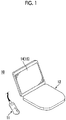
- Fig. 1 is a perspective view showing the acoustic wave image capturing apparatus 10 comprising the acoustic wave diagnostic apparatus 1 according to the first embodiment of the present invention.
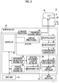
- Fig. 2 is a schematic diagram showing the overall configuration of the acoustic wave image capturing apparatus 10 shown in Fig. 1 .
- Fig. 3 is a diagram showing an example of the display of an ultrasound image Ib.
- Fig. 4 is a diagram showing an example of the display of a list N of measurement items on the ultrasound image Ib.
- Fig. 1 is a perspective view showing the acoustic wave image capturing apparatus 10 comprising the acoustic wave diagnostic apparatus 1 according to the first embodiment of the present invention.
- Fig. 2 is a schematic diagram showing the overall configuration of the acoustic wave image capturing apparatus 10 shown in Fig. 1 .
- Fig. 3 is a diagram showing an example of the display of an ultrasound image Ib.
- Fig. 4 is a diagram showing an example of the
- FIG. 5 is a diagram showing an example of selection in the list N of measurement items displayed on the ultrasound image Ib.
- Fig. 6 is a diagram showing an example of designation of a position on the ultrasound image Ib.
- Fig. 7 is a diagram showing an example of a measurement result R displayed on the ultrasound image Ib.
- the acoustic wave image capturing apparatus 10 has only a function of generating an ultrasound image based on a reflected ultrasound wave detection signal.
- the acoustic wave diagnostic apparatus according to the embodiment of the present invention may be mounted in an apparatus having both a function of generating a photoacoustic image based on a photoacoustic signal and a function of generating an ultrasound image based on a reflected ultrasound wave detection signal, or may be mounted in an apparatus having only a function of generating a photoacoustic image.
- the acoustic wave diagnostic apparatus can be mounted in any apparatus that can receive or store image data of at least one of a photoacoustic image or an ultrasound image of a two-dimensional image and display the received or stored image data even though the apparatus does not have any of the above-described functions.
- the acoustic wave image capturing apparatus 10 is configured as a so-called portable notebook computer type apparatus, as shown in Fig. 1 .
- the acoustic wave image capturing apparatus 10 of the present embodiment is of a notebook computer type, the present invention is not limited thereto, and may be of a tablet type or the like.
- the acoustic wave image capturing apparatus 10 comprises a probe 11 that is an ultrasound probe, an ultrasound unit 12, an image display unit 14, and an input unit 15.
- the ultrasound unit 12 is housed in the housing of Fig. 1 .
- the image display unit 14 is an image display screen including, for example, a liquid crystal display device, and is configured by a touch panel to which direct input can be performed by the operator.
- the image display unit 14 of the present embodiment also functions as the input unit 15.
- the image display unit 14 and the input unit 15 are configured to be able to display a color image.
- the components of the acoustic wave image capturing apparatus 10 will be sequentially described.
- the probe 11 has a function of emitting ultrasound waves toward a subject M that is a living body, for example.
- a subject M that is a living body
- the probe 11 has a function of detecting an acoustic wave U propagating through the subject M.
- the probe 11 emits (transmits) ultrasound waves (acoustic waves) to the subject M, and detects (receives) reflected ultrasound waves (reflected acoustic waves) that are returned by reflection from the subject M.
- the "acoustic wave” includes an ultrasound wave or a photoacoustic wave
- the “ultrasound wave” means an elastic wave transmitted by the probe and its reflected wave (reflected ultrasound wave).
- the acoustic wave emitted from the probe 11 is not limited to the ultrasound wave, and an acoustic wave having an audible frequency may be used as long as an appropriate frequency can be selected according to an examination target, measurement conditions, and the like.
- the probe 11 is configured as, for example, a sector scanning probe, a linear scanning probe, or a convex scanning probe.
- the type of probe used for acquisition of an acoustic wave image is appropriately selected according to an imaging part and the like.
- the probe 11 has a transducer array 20 that is an acoustic wave detector, and the transducer array 20 is housed in a housing 50.
- the transducer array 20 also functions as an ultrasound wave transmission element.
- the transducer array 20 is connected to a circuit for transmitting ultrasound waves and the like through wiring lines (not shown).
- the transducer array 20 has a plurality of ultrasound transducers arranged to be parallel in one direction.
- the ultrasound transducer is an electroacoustic transducer.
- the ultrasound transducer is a piezoelectric element formed of, for example, piezoelectric ceramics.
- the ultrasound transducer may be a piezoelectric element formed of a polymer film, such as polyvinylidene difluoride (PVDF).
- PVDF polyvinylidene difluoride
- the transducer array 20 is not limited thereto.
- a plurality of ultrasound transducers may be arranged in a two-dimensional manner.
- the ultrasound transducer in a case where an alternating voltage is applied to the ultrasound transducer, the ultrasound transducer generates an ultrasound wave having a frequency corresponding to the frequency of the alternating voltage, and the ultrasound wave is transmitted from the transducer array 20.
- transmission and reception of ultrasound waves may be separated from each other. That is, for example, ultrasound waves may be transmitted from a position different from the probe 11, and reflected ultrasound waves of the transmitted ultrasound waves may be received by the probe 11.
- the ultrasound unit 12 has a reception circuit 21, a reception memory 22, an ultrasound image generation unit 25, an image processing and storage unit 26, a display controller 27, a measurement item designation receiving unit 28, a detection measurement algorithm setting unit 29, a position designation receiving unit 30, a measurement unit 31, a transmission control circuit 34, and a controller 35.
- the acoustic wave diagnostic apparatus 1 that is an embodiment of the present invention is configured by the image display unit 14, the input unit 15, the image processing and storage unit 26, the display controller 27, the measurement item designation receiving unit 28, the detection measurement algorithm setting unit 29, the position designation receiving unit 30, the measurement unit 31, and the controller 35.
- the controller 35 controls each unit of the acoustic wave diagnostic apparatus 1, and controls each unit of the acoustic wave image capturing apparatus 10. In the case of acquiring an ultrasound image, the controller 35 transmits an ultrasound trigger signal for instructing the transmission control circuit 34 to transmit ultrasound waves. In a case where the ultrasound trigger signal is received, the transmission control circuit 34 causes the probe 11 to transmit ultrasound waves. The controller 35 transmits a sampling trigger signal to the reception circuit 21 according to the timing of ultrasound wave transmission, thereby starting the sampling of the reflected ultrasound wave signal.
- the reception circuit 21 receives the reflected ultrasound wave detection signal output from the transducer array 20 of the probe 11, and stores the received detection signal in the reception memory 22.
- the reception circuit 21 is configured to include a low noise amplifier, a variable gain amplifier, a low pass filter, and an AD converter.
- the reflected ultrasound wave detection signal output from the probe 11 is amplified by the low noise amplifier and then the gain is adjusted according to the depth by the variable gain amplifier, and high-frequency components are cut by the low pass filter and then conversion into a digital signal is performed by the AD converter and the digital signal is stored in the reception memory 22.
- the reception circuit 21 is configured by, for example, one integrated circuit (IC).
- the above-described low pass filter is provided to prevent aliasing noise from occurring at the time of AD conversion.
- the cut-off frequency of the low pass filter is generally set to a frequency that is about half the sampling frequency of AD conversion. Specifically, the cut-off frequency of the low pass filter is set to about 10 MHz to 30 MHz.
- a digitized reflected ultrasound wave detection signal is stored in the reception memory 22. More specifically, the reflected ultrasound wave detection signal is a signal obtained by detecting a reflected acoustic wave that is a reflected wave of an ultrasound wave, which is an acoustic wave emitted toward the subject M, in the subject M.
- the ultrasound image generation unit 25 generates an ultrasound image (tomographic image) by reconstructing the reflected ultrasound wave detection signal received from the reception memory 22. Specifically, the ultrasound image generation unit 25 adds a reflected ultrasound wave detection signal based on a signal output from each ultrasound transducer with a delay time corresponding to the position of each ultrasound transducer of the transducer array 20, thereby generating a reflected ultrasound wave detection signal for one line (delay addition method).
- the ultrasound image generation unit 25 may perform reconstruction using a circular back projection (CBP) method instead of the delay addition method.
- the ultrasound image generation unit 25 may perform reconstruction using a Hough transform method or a Fourier transform method.
- the reconstructed reflected ultrasound wave detection signals for a plurality of lines are subjected to signal processing, such as detection processing and logarithmic conversion processing, and then are transmitted to the display controller 27 through the image processing and storage unit 26 as signals for displaying an ultrasound image (tomographic image) regarding a cross section of the subject M.
- signal processing such as detection processing and logarithmic conversion processing
- the image processing and storage unit 26 performs various kinds of processing for image quality improvement, such as brightness correction, gradation correction, sharpness correction, and color correction, on the image data of the ultrasound image.
- the image processing and storage unit 26 of the present embodiment also functions as a storage unit that stores various databases and a storage unit that stores, as image data, a signal for displaying the image generated by the ultrasound image generation unit 25.
- the image processing and storage unit 26 of the acoustic wave diagnostic apparatus 1 and the acoustic wave image capturing apparatus 10 of the present embodiment comprises both an image processing function and a function as a storage unit, the acoustic wave diagnostic apparatus according to the embodiment of the present invention may have only a function as a storage unit without having an image processing function.
- the display controller 27 displays the ultrasound image Ib on the image display unit 14 as shown in Fig. 3 based on the above-described signal for displaying the ultrasound image.
- the measurement item designation receiving unit 28 receives designation of a measurement item relevant to the measurement target. Specifically, in a case where the measurement function is started on a user interface (UI) application by the operator, the list N of measurement items relevant to the measurement target is displayed on the image display unit 14 as shown in Fig. 4 . In each measurement item displayed in the list N of measurement items, the name of an organ and the measurement content regarding the organ are described. For example, an abdominal aorta diameter N1, a gallbladder size N2, a kidney size N3, a gallbladder wall thickness, and the like are displayed.
- UI user interface
- the present invention is not limited thereto, and only the name of the organ may be displayed.
- only items relevant to the names or abnormalities of lesions such as tumors, cysts, and bleeding may be displayed, or the names of lesions and the measurement content regarding the lesions may be displayed, or an item regarding abnormality and the measurement content regarding the item regarding abnormality may be displayed.
- the display content can be appropriately changed.
- the displayed name of the organ is associated with the measurement content, such as measuring the diameter, measuring the size, or measuring the length.
- an association table is stored in the image processing and storage unit 26, and the measurement content is selected based on the table in a case where the name of an organ is designated.
- the operator selects, for example, the gallbladder size N2 as a desired measurement item from the list N of measurement items using a finger P as shown in Fig. 5 .
- the measurement item designation receiving unit 28 receives the gallbladder size N2 selected by the operator as a measurement item.
- the measurement item designation receiving unit 28 of the present embodiment receives a selection item selected by a touch panel, the present invention is not limited thereto.
- an input device such as a mouse, a track pad, or a track ball, may be used as an input unit, and a selection item selected by the input unit may be received.
- the detection measurement algorithm setting unit 29 sets a detection algorithm and a measurement algorithm based on the measurement item received by the measurement item designation receiving unit 28.
- an algorithm for detecting a measurement target on an image differs depending on the type of organ, lesion, or the like.
- the algorithm for measuring a measurement target on the image also differs depending on the measurement content, such as measuring the diameter, measuring the size, or measuring the length.
- the detection measurement algorithm setting unit 29 stores an algorithm corresponding to each measurement target and an algorithm corresponding to each measurement content as an association table, and sets a detection measurement algorithm with reference to the above-described association table in a case where the measurement item designation receiving unit 28 receives a measurement item.
- the detection measurement algorithm a known algorithm that is generally used can be used.
- the algorithm referred to herein defines a procedure (calculation procedure) for achieving a certain purpose (detection or measurement).
- the algorithm referred to herein is implemented as a software program in an apparatus and is executed by a processor.
- a pattern data similarity is calculated while searching for an image with a template, and it is considered that a target is present in a place where the similarity is equal to or greater than a predetermined threshold value and is the maximum.
- a machine learning method described in Csurka et al.: Visual Categorization with Bags of Keypoints, Proc. of ECCV Workshop on Statistical Learning in Computer Vision, pp.
- the position designation receiving unit 30 receives designation of the position of a measurement target on the ultrasound image Ib displayed on the image display unit 14. Specifically, in a case where the measurement item received by the measurement item designation receiving unit 28 is the gallbladder size N2, the operator desires to measure the size of the gallbladder. Therefore, the measurement target is the gallbladder. Then, as shown in Fig. 6 , the operator designates a position where the operator himself or herself thinks that the gallbladder is present on the ultrasound image Ib, for example, the tip of the arrow in Fig. 6 using the finger P. The position designation receiving unit 30 receives the position designated by the operator as a measurement target position.
- the measurement unit 31 detects the measurement target based on the received position and the detection measurement algorithm set by the detection measurement algorithm setting unit 29, and performs measurement for the detected measurement target.
- the measurement unit 31 determines the position of a detection range for detecting the measurement target based on the received position, and detects the inside of the detection range at the determined position.
- the size of the detection range is set in the measurement unit 31 in advance, but can be changed by the operator.
- the measurement unit 31 first detects the gallbladder on the ultrasound image Ib within the detection range based on the detection algorithm set by the detection measurement algorithm setting unit 29. The measurement unit 31 detects the accurate position and region of the gallbladder on the ultrasound image Ib. Then, the measurement unit 31 determines an optimal measurement point for the detected gallbladder. Specifically, as shown in Fig. 7 , the measurement unit 31 determines two longest distance points on the boundary surrounding the gallbladder region on the ultrasound image Ib as measurement points K1 and K2, and measures the length of a line K3 connecting the measurement points K1 and K2 to each other. In Fig.
- the length of the line K3 is 56 mm.
- the measurement unit 31 displays the measurement points K1 and K2 and the line K3 and the measurement target and the length as a measurement result R, that is, gallbladder: 56 mm, on the image display unit 14 through the image processing and storage unit 26 and the display controller 27.
- the measurement unit 31 determines the position of the detection range for detecting the measurement target based on the position received by the position designation receiving unit 30.
- the measurement unit 31 may further determine a measurement position for measuring the measurement target based on the position received by the position designation receiving unit 30, that is, the positions of the measurement points K1 and K2.
- the measurement unit 31 determines which diameter is to be measured based on the received position.
- the measurement unit 31 can determine the shortest line passing through the received position as the line K3 and determine points at both ends of the line K3 as the measurement points K1 and K2.
- the measurement unit 31 does not need to determine the position of the range for detecting the measurement target. For this reason, the measurement unit 31 may determine only the measurement position for measuring the measurement target, that is, the positions of the measurement points K1 and K2.
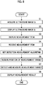
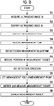
- Fig. 8 is a flowchart showing a method of a series of processes of the acoustic wave diagnostic apparatus 1 shown in Fig. 2 .
- the image processing and storage unit 26 receives and stores image data of the ultrasound image Ib generated by the ultrasound image generation unit 25, thereby acquiring the ultrasound image Ib (step S1).
- the image processing and storage unit 26 receives and stores the image data of the ultrasound image Ib generated by the ultrasound image generation unit 25, thereby acquiring the ultrasound image Ib.
- the ultrasound image Ib may be acquired by inputting the image data of the ultrasound image Ib, which is stored in external storage means in advance, through an input and output unit (not shown) provided in the acoustic wave diagnostic apparatus 1.
- the present invention can also be applied to a case where the image data of the ultrasound image Ib generated by the ultrasound image generation unit 25 is displayed on the image display unit 14 by the display controller 27 without being temporarily stored in the image processing and storage unit 26.
- the display controller 27 displays the image data of the ultrasound image Ib, which is stored in the image processing and storage unit 26 and has been subjected to various kinds of image processing, on the image display unit 14 (step S2). Then, in a case where the measurement function is started by the operator on the UI application, the display controller 27 displays the list N of measurement items relevant to the measurement target on the image display unit 14 as shown in Fig. 4 (step S3).
- the operator designates the gallbladder size N2 as a desired measurement item from the list N of measurement items using the finger P, and the measurement item designation receiving unit 28 receives the gallbladder size N2 selected by the operator as a measurement item (step S4).
- the detection measurement algorithm setting unit 29 sets the detection measurement algorithm for the measurement item received by the measurement item designation receiving unit 28, that is, the gallbladder size (step S5).
- the position designation receiving unit 30 receives designation of the position of the measurement target, that is, the gallbladder on the ultrasound image Ib displayed on the image display unit 14 (step S6). Then, the measurement unit 31 detects the inside of the detection range based on the detection algorithm set by the detection measurement algorithm setting unit 29, and detects the accurate position and region of the gallbladder on the ultrasound image Ib. The measurement unit 31 determines the optimal measurement points K1 and K2 for the detected gallbladder, and measures the length of the line K3 connecting the measurement points K1 and K2 to each other (step S7).
- the measurement unit 31 displays the measurement points K1 and K2 and the line K3 and the measurement target and the length as the measurement result R, that is, gallbladder: 56 mm, on the image display unit 14 through the image processing and storage unit 26 and the display controller 27 (step S8).
- the acoustic wave diagnostic apparatus 1 measures the measurement target.
- the measurement unit 31 can automatically detect and measure a measurement target M1 simply by designating the approximate position of the measurement target M1 on the acoustic wave image displayed on the image display unit 14 by the operator. Therefore, it is possible to measure the measurement target M1 quickly and easily by reducing the time or effort required for the operator to input measurement points and to perform measurement with reduced variations by the operator.
- Fig. 9 is a perspective view showing the acoustic wave image capturing apparatus 10-2 comprising the acoustic wave diagnostic apparatus 1
- Fig. 10 is a schematic diagram showing the overall configuration of the acoustic wave image capturing apparatus 10-2 shown in Fig. 9 .
- the acoustic wave image capturing apparatus 10-2 has both a function of generating a photoacoustic image based on a photoacoustic signal and a function of generating an ultrasound image based on a reflected ultrasound wave detection signal.
- the acoustic wave diagnostic apparatus according to the embodiment of the present invention may be mounted in an apparatus having only the function of generating a photoacoustic image, or may be mounted in an apparatus having only the function of generating an ultrasound image.
- the acoustic wave diagnostic apparatus can be mounted in any apparatus that can receive or store image data of at least one of a photoacoustic image or an ultrasound image of a two-dimensional image and display the received or stored image data even though the apparatus does not have any of the above-described functions.
- the acoustic wave image capturing apparatus 10-2 is configured as a so-called tower type apparatus, as shown in Fig. 9 .
- the acoustic wave image capturing apparatus 10-2 comprises a probe 11 that is an ultrasound probe, an ultrasound unit 12, a laser unit 13, an image display unit 14, and an input unit 15.
- the ultrasound unit 12 and the laser unit 13 are housed in a housing 10C.
- the image display unit 14 is an image display screen including, for example, a liquid crystal display device, and is configured by a touch panel to which direct input can be performed by the operator.
- the input unit 15 also comprises, for example, a touch panel 15T different from the image display unit 14, a plurality of input buttons 15B, a plurality of input keys 15K, and the like.
- the image display unit 14 of the present embodiment also functions as the input unit 15.
- Each of the image display unit 14 and the touch panel 15T is configured to be able to display a color image.
- the components of the acoustic wave image capturing apparatus 10-2 will be sequentially described.
- the probe 11 has a function of emitting measurement light and ultrasound waves toward the subject M that is a living body, for example.
- the shape of the probe 11 is schematically shown.
- the probe 11 has a function of detecting the acoustic wave U propagating through the subject M.
- the probe 11 emits measurement light to the subject M, and detects photoacoustic waves generated in the subject due to the emission of the measurement light.
- the probe 11 emits (transmits) ultrasound waves (acoustic waves) to the subject M, and detects (receives) reflected ultrasound waves (reflected acoustic waves) that are returned by reflection from the subject M.
- the "acoustic wave” includes an ultrasound wave or a photoacoustic wave
- the “ultrasound wave” means an elastic wave transmitted by the probe and its reflected wave (reflected ultrasound wave).
- the "photoacoustic wave” means an elastic wave that is generated in a case where an absorber 65 absorbs measurement light.
- the acoustic wave emitted from the probe 11 is not limited to the ultrasound wave, and an acoustic wave having an audible frequency may be used as long as an appropriate frequency can be selected according to an examination target, measurement conditions, and the like.
- the absorber 65 in the subject M for example, a blood vessel, a metal member, and the like can be mentioned.
- the probe 11 is configured as, for example, a sector scanning probe, a linear scanning probe, or a convex scanning probe.
- the type of probe used for acquisition of an acoustic wave image is appropriately selected according to an imaging part and the like.
- An optical fiber 60 that makes a connection between the laser unit 13 and the probe 11 is connected to the probe 11.
- Laser light L that is measurement light emitted from the laser unit 13 is guided to a light emitting unit 40 by the optical fiber 60.
- the probe 11 has the transducer array 20, which is an acoustic wave detector, and the light emitting unit 40.
- the probe 11 has two light emitting units 40.
- the two light emitting units 40 are disposed at positions facing each other with the transducer array 20 interposed therebetween.
- the transducer array 20 and the two light emitting units 40 are housed in the housing 50.
- the transducer array 20 also functions as an ultrasound wave transmission element.
- the transducer array 20 is connected to a circuit for transmitting ultrasound waves, a circuit for receiving acoustic waves, and the like through wiring lines (not shown).
- the transducer array 20 has a plurality of ultrasound transducers arranged to be parallel in one direction.
- the ultrasound transducer is an electroacoustic transducer.
- the ultrasound transducer is a piezoelectric element formed of, for example, piezoelectric ceramics.
- the ultrasound transducer may be a piezoelectric element formed of a polymer film, such as polyvinylidene difluoride (PVDF).
- PVDF polyvinylidene difluoride
- the ultrasound transducer converts the received acoustic wave U into an electrical signal.
- the probe 11 may have an acoustic lens on the subject side of the transducer array 20.
- the transducer array 20 is not limited thereto.
- a plurality of ultrasound transducers may be arranged in a two-dimensional manner.
- the ultrasound transducer in a case where an alternating voltage is applied to the ultrasound transducer, the ultrasound transducer generates an ultrasound wave having a frequency corresponding to the frequency of the alternating voltage, and the ultrasound wave is transmitted from the transducer array 20.
- transmission and reception of ultrasound waves may be separated from each other. That is, for example, ultrasound waves may be transmitted from a position different from the probe 11, and reflected ultrasound waves of the transmitted ultrasound waves may be received by the probe 11.
- the light emitting unit 40 emits the laser light L guided by the optical fiber 60 toward the subject M.
- the light emitting unit 40 is configured by the distal end portion of the optical fiber 60, that is, an end portion far from the laser unit 13 that is a light source of measurement light.
- the two light emitting units 40 are disposed on both sides of the transducer array 20, for example, in the elevation direction with the transducer array 20 interposed therebetween.
- the "elevation direction" is a direction perpendicular to the arrangement direction and parallel to the detection surface of the transducer array 20 in a case where a plurality of ultrasound transducers are arranged in a one dimensional manner.
- the light emitting unit 40 may include a light guide plate and a diffusion plate that are optically coupled to the distal end of the optical fiber 60.
- a light guide plate for example, an acrylic plate or a quartz plate is used.
- a lens diffusion plate in which microlenses are randomly disposed on the substrate can be used.
- a holographic diffusion plate may be used, or an engineering diffusion plate may be used.
- a quartz plate in which diffusion fine particles are dispersed may be used as the diffusion plate.
- the laser unit 13 emits the laser light L as measurement light.
- the laser unit 13 includes a flash lamp excitation Q switch solid-state laser, such as a Q switch alexandrite laser, for example.
- the laser unit 13 receives a trigger signal emitted from the controller 35 of the ultrasound unit 12, for example.
- the laser unit 13 outputs the laser light L in a case where a trigger signal is received. It is preferable that the laser unit 13 outputs the pulsed laser light L having a pulse width of 1 to 100 nsec (nanosecond).
- the wavelength of the laser light L is appropriately selected according to the light absorption characteristics of the absorber 65 in the subject M that is a measurement target.
- the wavelength of the laser light L is a wavelength belonging to the near-infrared wavelength band.
- the near-infrared wavelength band means a wavelength band of about 700 to 2500 nm.
- the wavelength of the laser light L is arbitrary, and is not limited to the wavelength belonging to the near-infrared wavelength band.
- the laser unit 13 may emit the laser light L having a single wavelength, or may emit the laser light L having a plurality of wavelengths.
- a plurality of wavelengths for example, a combination of 750 nm and 800 nm can be considered.
- the laser light L includes a plurality of wavelengths
- light beams having the plurality of wavelengths may be simultaneously emitted or may be emitted while being switched alternately.
- the laser unit 13 is not limited to including an alexandrite laser.
- Examples of the laser unit 13 include an yttrium aluminum garnet (YAG)-second harmonic generation (SHG)-optical parametric oscillation (OPO) laser capable of outputting laser light in a near-infrared wavelength band, a YAG laser that does not perform wavelength conversion, or a titanium-sapphire (Ti-Sapphire) laser.
- the laser unit 13 is not limited to the flash lamp excitation solid-state laser, and may include a laser diode excitation solid-state laser.
- the optical fiber 60 guides the laser light L, which is emitted from the laser unit 13, to the two light emitting units 40.
- a known optical fiber such as a quartz fiber can be used as the optical fiber 60.
- the optical fiber 60 for example, one thick optical fiber may be used, or a bundle fiber in which a plurality of optical fiber strands are bundled may be used.
- the laser light L may be incident on the light incidence end surfaces of the plurality of optical fiber strands bundled together, the plurality of optical fiber strands may be branched into two groups, and each of the light emitting ends of the optical fiber strands branched into two groups may be used as the light emitting unit 40.
- the ultrasound unit 12 has a reception circuit 21, a reception memory 22, data separation unit 23, a photoacoustic image generation unit 24, an ultrasound image generation unit 25, an image processing and storage unit 26, a display controller 27, a measurement item designation receiving unit 28, a detection measurement algorithm setting unit 29, a position designation receiving unit 30, a measurement unit 31, a transmission control circuit 34, and a controller 35.
- the acoustic wave diagnostic apparatus 1 that is an embodiment of the present invention is configured by the image display unit 14, the input unit 15, the image processing and storage unit 26, the display controller 27, the measurement item designation receiving unit 28, the detection measurement algorithm setting unit 29, the position designation receiving unit 30, the measurement unit 31, and the controller 35.
- the controller 35 controls each unit of the acoustic wave diagnostic apparatus 1, and controls each unit of the acoustic wave image capturing apparatus 10-2.
- the controller 35 comprises a trigger control circuit (not shown). For example, in the case of acquiring a photoacoustic image, the trigger control circuit transmits a light trigger signal to the laser unit 13. In a case where the optical trigger signal is received, the laser unit 13 turns on the flash lamp of the excitation source in the Q switch solid-state laser to start excitation of the laser rod. While the excitation state of the laser rod is maintained, the laser unit 13 can output the laser light L.
- the trigger control circuit of the controller 35 transmits a Q switch trigger signal to the laser unit 13 after transmitting the optical trigger signal.
- the laser unit 13 opens the Q switch of the Q switch solid-state laser to output the laser light L.
- the timing at which the laser light L is output from the laser unit 13 is controlled by the Q switch trigger signal.
- the controller 35 transmits a Q switch trigger signal, and transmits a sampling trigger signal to the reception circuit 21.
- the sampling trigger signal defines the start timing of photoacoustic signal sampling in an analog to digital converter (AD converter) of the reception circuit 21. By starting sampling by the reception circuit that receives the sampling trigger signal, the photoacoustic signal can be sampled in synchronization with the output of the laser light L.
- AD converter analog to digital converter
- the controller 35 transmits an ultrasound trigger signal for instructing the transmission control circuit 34 to transmit ultrasound waves.
- the transmission control circuit 34 causes the probe 11 to transmit ultrasound waves.
- the controller 35 transmits a sampling trigger signal to the reception circuit 21 according to the timing of ultrasound wave transmission, thereby starting the sampling of the reflected ultrasound wave signal.
- the reception circuit 21 receives the photoacoustic wave detection signal output from the transducer array 20 of the probe 11, and stores the received detection signal in the reception memory 22.
- the reception circuit 21 is configured to include a low noise amplifier, a variable gain amplifier, a low pass filter, and an AD converter.
- the photoacoustic wave detection signal output from the probe 11 is amplified by the low noise amplifier and then the gain is adjusted according to the depth by the variable gain amplifier, and high-frequency components are cut by the low pass filter and then conversion into a digital signal is performed by the AD converter and the digital signal is stored in the reception memory 22.
- the reception circuit 21 is configured by, for example, one integrated circuit (IC).
- the above-described low pass filter is provided to prevent aliasing noise from occurring at the time of AD conversion.
- the cut-off frequency of the low pass filter is generally set to a frequency that is about half the sampling frequency of AD conversion. Specifically, the cut-off frequency of the low pass filter is set to about 10 MHz to 30 MHz.
- the probe 11 outputs a photoacoustic wave detection signal and a reflected ultrasound wave detection signal.
- a photoacoustic wave detection signal and a reflected ultrasound wave detection signal that are digitized are stored in the reception memory 22.
- the photoacoustic wave detection signal is a signal obtained by detecting a photoacoustic wave that is generated from the inside of the subject M by receiving the laser light L emitted toward the subject M.
- the reflected ultrasound wave detection signal is a signal obtained by detecting a reflected acoustic wave that is a reflected wave of an ultrasound wave, which is an acoustic wave emitted toward the subject M, in the subject M.
- the data separation unit 23 reads the photoacoustic image data, that is, the digitized photoacoustic wave detection signal from the reception memory 22, and transmits the digitized photoacoustic wave detection signal to the photoacoustic image generation unit 24.
- the data separation unit 23 reads the reflected ultrasound image data, that is, the digitized reflected ultrasound wave detection signal from the reception memory 22, and transmits the digitized reflected ultrasound wave detection signal to the ultrasound image generation unit 25.
- the photoacoustic image generation unit 24 generates a photoacoustic image by reconstructing the photoacoustic wave detection signal received from the reception memory 22 through the data separation unit 23. Specifically, the photoacoustic image generation unit 24 adds a photoacoustic wave detection signal based on a signal output from each ultrasound transducer with a delay time corresponding to the position of each ultrasound transducer of the transducer array 20, thereby generating a photoacoustic wave detection signal for one line (delay addition method).
- the photoacoustic image generation unit 24 may perform reconstruction using a circular back projection (CBP) method instead of the delay addition method. Alternatively, the photoacoustic image generation unit 24 may perform reconstruction using a Hough transform method or a Fourier transform method.
- CBP circular back projection
- the reconstructed photoacoustic wave detection signals for a plurality of lines are subjected to signal processing, such as detection processing and logarithmic conversion processing, and then are transmitted to the display controller 27 through the image processing and storage unit 26 as signals for displaying a photoacoustic image (tomographic image) regarding a cross section of the subject M.
- signal processing such as detection processing and logarithmic conversion processing
- the ultrasound image generation unit 25 performs basically the same processing as for the photoacoustic wave detection signal on the reflected ultrasound wave detection signal received from the reception memory 22 through the data separation unit 23, thereby generating reflected ultrasound wave detection signals for a plurality of lines indicating an ultrasound image (tomographic image).
- the reflected ultrasound wave detection signal generated as described above is transmitted to the display controller 27 through the image processing and storage unit 26 as a signal for displaying an ultrasound image regarding a cross section of the subject M.
- the image processing and storage unit 26 performs various kinds of processing for image quality improvement, such as brightness correction, gradation correction, sharpness correction, and color correction, on the image data of the photoacoustic image and the ultrasound image.
- the image processing and storage unit 26 of the present embodiment also functions as a storage unit that stores various databases and a storage unit that stores, as image data, a signal for displaying the image generated by the photoacoustic image generation unit 24 or the ultrasound image generation unit 25.
- the image processing and storage unit 26 of the acoustic wave diagnostic apparatus 1 and the acoustic wave image capturing apparatus 10-2 of the present embodiment comprises both an image processing function and a function as a storage unit
- the acoustic wave diagnostic apparatus according to the embodiment of the present invention may have only a function as a storage unit without having an image processing function.
- the display controller 27 displays a photoacoustic image on the image display unit 14 based on the above-described signal for displaying the photoacoustic image.
- the ultrasound image Ib is displayed on the image display unit 14 as shown in Fig. 3 .
- These two types of images are displayed on the image display unit 14 separately or as a composite image.
- the display controller 27 performs image composition by superimposing a photoacoustic image and an ultrasound image, for example. In a case where the photoacoustic image and the ultrasound image are superimposed and displayed, a portion that cannot be imaged in the photoacoustic image can be observed in the ultrasound image.
- the acoustic wave image displayed on the image display unit 14 will be described below as the ultrasound image Ib.
- the present invention is not limited thereto, and a photoacoustic wave image or a composite image in which a photoacoustic image and an ultrasound image are superimposed can be displayed and measured.
- the measurement item designation receiving unit 28 receives designation of a measurement item relevant to the measurement target. Specifically, in a case where the measurement function is started on a user interface (UI) application by the operator, the list N of measurement items relevant to the measurement target is displayed on the image display unit 14 as shown in Fig. 4 . In each measurement item displayed in the list N of measurement items, the name of the organ and the measurement content regarding the organ are described. For example, an abdominal aorta diameter N1, a gallbladder size N2, a kidney size N3, a gallbladder wall thickness, and the like are displayed.
- UI user interface
- the present invention is not limited thereto, and only the name of the organ may be displayed.
- only items relevant to the names or abnormalities of lesions such as tumors, cysts, and bleeding may be displayed, or the names of lesions and the measurement content regarding the lesions may be displayed, or an item regarding abnormality and the measurement content regarding the item regarding abnormality may be displayed.
- the display content can be appropriately changed.
- the displayed name of the organ is associated with the measurement content, such as measuring the diameter, measuring the size, or measuring the length.
- an association table is stored in the image processing and storage unit 26, and the measurement content is selected based on the table in a case where the name of an organ is designated.
- the operator selects, for example, the gallbladder size N2 as a desired measurement item from the list N of measurement items using the finger P as shown in Fig. 5 .
- the measurement item designation receiving unit 28 receives the gallbladder size N2 selected by the operator as a measurement item.
- the measurement item designation receiving unit 28 of the present embodiment receives a selection item selected by a touch panel, the present invention is not limited thereto.
- an input device such as a mouse, a track pad, or a track ball, may be used as an input unit, and a selection item selected by the input unit may be received.
- the detection measurement algorithm setting unit 29 sets a detection algorithm and a measurement algorithm based on the measurement item received by the measurement item designation receiving unit 28.
- an algorithm for detecting a measurement target on an image differs depending on the type of organ, lesion, or the like.
- the algorithm for measuring a measurement target on the image also differs depending on the measurement content, such as measuring the diameter, measuring the size, or measuring the length.
- the detection measurement algorithm setting unit 29 stores an algorithm corresponding to each measurement target and an algorithm corresponding to each measurement content as an association table, and sets a detection measurement algorithm with reference to the above-described association table in a case where the measurement item designation receiving unit 28 receives a measurement item.
- the detection measurement algorithm a known algorithm that is generally used can be used.
- the algorithm referred to herein defines a procedure (calculation procedure) for achieving a certain purpose (detection or measurement).
- the algorithm referred to herein is implemented as a software program in an apparatus and is executed by a processor.
- a pattern data similarity is calculated while searching for an image with a template, and it is considered that a target is present in a place where the similarity is equal to or greater than a predetermined threshold value and is the maximum.
- a machine learning method described in Csurka et al.: Visual Categorization with Bags of Keypoints, Proc. of ECCV Workshop on Statistical Learning in Computer Vision, pp.
- the position designation receiving unit 30 receives designation of the position of a measurement target on the ultrasound image Ib displayed on the image display unit 14. Specifically, in a case where the measurement item received by the measurement item designation receiving unit 28 is the gallbladder size N2, the operator desires to measure the size of the gallbladder. Therefore, the measurement target is the gallbladder. Then, as shown in Fig. 6 , the operator designates a position where the operator himself or herself thinks that the gallbladder is present on the ultrasound image Ib, for example, the tip of the arrow in Fig. 6 using the finger P. The position designation receiving unit 30 receives the position designated by the operator as a measurement target position.
- the measurement unit 31 detects the measurement target based on the received position and the detection measurement algorithm set by the detection measurement algorithm setting unit 29, and performs measurement for the detected measurement target.
- the measurement unit 31 determines the position of a detection range for detecting the measurement target based on the received position, and detects the inside of the detection range at the determined position.
- the size of the detection range is set in the measurement unit 31 in advance, but can be changed by the operator.
- the measurement unit 31 first detects the gallbladder on the ultrasound image Ib within the detection range based on the detection algorithm set by the detection measurement algorithm setting unit 29. The measurement unit 31 detects the accurate position and region of the gallbladder on the ultrasound image Ib. Then, the measurement unit 31 determines an optimal measurement point for the detected gallbladder. Specifically, as shown in Fig. 7 , the measurement unit 31 determines two longest distance points on the boundary surrounding the gallbladder region on the ultrasound image Ib as measurement points K1 and K2, and measures the length of a line K3 connecting the measurement points K1 and K2 to each other. In Fig.
- the length of the line K3 is 56 mm.
- the measurement unit 31 displays the measurement points K1 and K2 and the line K3 and the measurement target and the length as a measurement result R, that is, gallbladder: 56 mm, on the image display unit 14 through the image processing and storage unit 26 and the display controller 27.
- the measurement unit 31 determines the position of the detection range for detecting the measurement target based on the position received by the position designation receiving unit 30.
- the measurement unit 31 may further determine the measurement position for measuring the measurement target, that is, the positions of the measurement points K1 and K2.
- the measurement unit 31 determines which diameter is to be measured based on the received position.
- the measurement unit 31 can determine the shortest line passing through the received position as the line K3 and determine points at both ends of the line K3 as the measurement points K1 and K2.
- the measurement unit 31 does not need to determine the position of the range for detecting the measurement target. For this reason, the measurement unit 31 may determine only the measurement position for measuring the measurement target, that is, the positions of the measurement points K1 and K2.
- the image processing and storage unit 26 receives and stores image data of the ultrasound image Ib generated by the ultrasound image generation unit 25, thereby acquiring the ultrasound image Ib (step S1).
- the image processing and storage unit 26 receives and stores the image data of the ultrasound image Ib generated by the ultrasound image generation unit 25, thereby acquiring the ultrasound image Ib.
- the ultrasound image Ib may be acquired by inputting the image data of the ultrasound image Ib, which is stored in external storage means in advance, through an input and output unit (not shown) provided in the acoustic wave diagnostic apparatus 1.
- the present invention can also be applied to a case where the image data of the ultrasound image Ib generated by the ultrasound image generation unit 25 is displayed on the image display unit 14 by the display controller 27 without being temporarily stored in the image processing and storage unit 26.
- the display controller 27 displays the image data of the ultrasound image Ib, which is stored in the image processing and storage unit 26 and has been subjected to various kinds of image processing, on the image display unit 14 (step S2). Then, in a case where the measurement function is started by the operator on the UI application, the display controller 27 displays the list N of measurement items relevant to the measurement target on the image display unit 14 as shown in Fig. 4 (step S3).
- the operator designates the gallbladder size N2 as a desired measurement item from the list N of measurement items using the finger P, and the measurement item designation receiving unit 28 receives the gallbladder size N2 selected by the operator as a measurement item (step S4).
- the detection measurement algorithm setting unit 29 sets the detection measurement algorithm for the measurement item received by the measurement item designation receiving unit 28, that is, the gallbladder size (step S5).
- the position designation receiving unit 30 receives designation of the position of the measurement target, that is, the gallbladder on the ultrasound image Ib displayed on the image display unit 14 (step S6). Then, the measurement unit 31 detects the inside of the detection range based on the detection algorithm set by the detection measurement algorithm setting unit 29, and detects the accurate position and region of the gallbladder on the ultrasound image Ib. The measurement unit 31 determines the optimal measurement points K1 and K2 for the detected gallbladder, and measures the length of the line K3 connecting the measurement points K1 and K2 to each other (step S7).
- the measurement unit 31 displays the measurement points K1 and K2 and the line K3 and the measurement target and the length as the measurement result R, that is, gallbladder: 56 mm, on the image display unit 14 through the image processing and storage unit 26 and the display controller 27 (step S8).
- the acoustic wave diagnostic apparatus 1 measures the measurement target.
- the measurement unit 31 can automatically detect and measure a measurement target M1 simply by designating the approximate position of the measurement target M1 on the acoustic wave image displayed on the image display unit 14 by the operator. Therefore, it is possible to measure the measurement target M1 quickly and easily by reducing the time or effort required for the operator to input measurement points and to perform measurement with reduced variations by the operator.
- Fig. 11 is a schematic diagram showing the overall configuration of the acoustic wave image capturing apparatus 10-3 comprising the acoustic wave diagnostic apparatus 1-2 according to the second embodiment of the present invention
- Fig. 12 is a diagram illustrating processing by the acoustic wave diagnostic apparatus 1-2 shown in Fig. 11
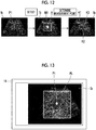
- Fig. 13 is a diagram showing an example of the size of a detection range on the ultrasound image Ib
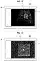
- Fig. 14 is a diagram showing another example of the size of the detection range on the ultrasound image Ib
- Fig. 11 is a schematic diagram showing the overall configuration of the acoustic wave image capturing apparatus 10-3 comprising the acoustic wave diagnostic apparatus 1-2 according to the second embodiment of the present invention
- Fig. 12 is a diagram illustrating processing by the acoustic wave diagnostic apparatus 1-2 shown in Fig. 11
- Fig. 13 is a diagram showing an example of the size of a detection range on the ultrasound image Ib
- Fig. 14 is a diagram showing another
- Fig. 15 is a diagram showing an example of the position of the detection range on the ultrasound image Ib
- Fig. 16 is a diagram showing another example of the position of the detection range on the ultrasound image Ib
- Fig. 17 is a diagram illustrating the detection accuracy within the detection range
- Fig. 18 is a diagram showing an example of the detection order on the ultrasound image Ib
- Fig. 19 is a diagram showing another example of the detection order on the ultrasound image Ib.
- the acoustic wave diagnostic apparatus 1-2 shown in Fig. 11 is obtained by further providing a detection condition setting unit 32 in the acoustic wave diagnostic apparatus 1 shown in Fig. 9
- the other components are the same as those of the acoustic wave diagnostic apparatus 1 shown in Fig. 9 . Therefore, the same components are denoted by the same reference numerals for the sake of convenience, and the description thereof will be omitted herein.
- the acoustic wave diagnostic apparatus 1-2 shown in Fig. 11 comprises the detection condition setting unit 32.
- the detection condition setting unit 32 determines at least one of the position, size, detection accuracy, or detection order of the detection range A of the measurement target M1 based on at least one of a position P1 on the ultrasound image Ib shown in Fig. 12 received by the position designation receiving unit 30 or the measurement item received by the measurement item designation receiving unit 28.
- the detection condition setting unit 32 determines the size of the detection range A of the measurement target M1 based on the measurement item. For example, in a case where the measurement target M1 is a relatively large organ, such as a kidney, the measurement unit 31 detects, for example, a quadrangular detection range AL of 100 pixels vertically and horizontally with the received position PI as the center, as shown in Fig. 13 .
- the measurement unit 31 detects, for example, a quadrangular detection range AS of 20 pixels vertically and horizontally with the received position PI as the center, as shown in Fig. 14 . Since the range in which the presence of the measurement target M1 is assumed differs depending on the size of the measurement target M1, the processing time required to detect the measurement target M1 can be shortened by changing the size of the detection range A according to the size of the measurement target M1.
- the detection condition setting unit 32 determines the position of the detection range A of the measurement target M1 based on the position P1 on the ultrasound image Ib shown in Fig. 12 received by the position designation receiving unit 30. For example, as shown in Fig. 15 , in a case where the position PI is present near the center of the ultrasound image Ib, the measurement unit 31 detects a quadrangular detection range AC that is vertically and horizontally symmetrical with the position PI as the center.
- the measurement unit 31 detects a quadrangular detection range AC that is vertically symmetrical and horizontally asymmetrical so as not to protrude from the ultrasound image Ib with the position PI as the center.
- the range in which the presence of the measurement target M1 is assumed differs depending on the size of the measurement target M1. Therefore, the size of the detection range A may be reduced by changing the position of the detection range A according to the position PI received by the position designation receiving unit 30. In a case where the size of the detection range A is reduced, the processing time required to detect the measurement target M1 can be shortened.
- the detection condition setting unit 32 determines the detection accuracy of the detection range A of the measurement target M1 based on the measurement item. For example, in a case where the measurement target M1 is a relatively large organ, such as a kidney, the measurement unit 31 roughly detects, for example, six 10-pixel regions horizontally and six 10-pixel regions vertically in the detection range AL as shown in Fig. 17 .
- the measurement unit 31 finely detects, for example, six 3-pixel regions horizontally and six 3-pixel regions vertically in the detection range AS as shown in Fig. 17 . Since the range in which the presence of the measurement target M1 is assumed differs depending on the size of the measurement target M1, the balance of the detection accuracy and the processing time required to detect the measurement target M1 and can be improved by changing the detection accuracy in the detection range A according to the size of the measurement target M1. In the present embodiment, in a case where the detection accuracy is changed based on the size of the measurement target M1, the size of the detection range is also changed based on the size of the measurement target M1. However, the present invention is not limited thereto, and only the detection accuracy may be changed.
- the detection condition setting unit 32 determines the detection order of the measurement target M1 based on the measurement item and the position PI received by the position designation receiving unit 30. For example, in a case where the measurement item is a round organ, such as a gallbladder short axis surface size or an abdominal aorta short axis diameter, the detection condition setting unit 32 determines the detection order of the measurement target M1 so that the detection is performed in the order indicated by a scanning line S1 in a spiral shape from the center toward the outside with the position PI as the center, as shown in Fig. 18 .
- the interval between the scanning lines S1 may be equal, or the interval may be increased toward the outside or can be appropriately changed.
- the scanning may be clockwise or counterclockwise, or can be appropriately changed.
- the spiral shape is set in the present embodiment, the present invention is not limited thereto.
- a plurality of quadrangles whose sizes increase toward the outside with the position PI as the center may be used as scanning lines.
- the interval between the scanning lines may be equal, or the interval may be increased toward the outside or can be appropriately changed.
- the scanning may be clockwise or counterclockwise, or the rotation direction may be changed for each quadrangle or can be appropriately changed.
- the shape of the scanning line is not limited to a quadrangle, and the shape can be appropriately changed.
- the detection condition setting unit 32 determines the detection order of the measurement target M1 so that detection in the horizontal direction (arrow S2 in the diagram) is performed and then detection in the vertical direction is performed as shown in Fig. 19 .
- detection in the horizontal direction passing through the position PI is performed in the order of the left direction and the right direction, and then upward movement is made to perform detection in the horizontal direction in the order of the left direction and the right direction, and downward movement from the position PI is made to perform detection in the horizontal direction in the order of the left direction and the right direction, so that the detection is performed in a direction away from the position PI in the order of the upward direction and the downward direction.
- the order of detection is not limited thereto, and detection in the horizontal direction on the lower side may be performed after detection in the horizontal direction on the upper side is entirely performed, or the order of detection can be appropriately changed.
- the detection condition setting unit 32 changes the size or the detection accuracy of the detection range described above, and determines the detection order of the measurement target M1 based on the measurement item and the position PI received by the position designation receiving unit 30.
- the detection condition setting unit 32 of the present invention is not limited thereto.
- the detection condition setting unit 32 may change only the size or the detection accuracy of the detection range described above, or may determine only the detection order of the measurement target M1.
- Fig. 20 is a flowchart showing a method of a series of processes of the acoustic wave diagnostic apparatus 1-2 shown in Fig. 11 . Since steps S21 to S26 in Fig. 20 are the same as steps S1 to S16 in the flowchart of Fig. 8 , the description thereof will be omitted herein.
- the detection condition setting unit 32 determines at least one of the position, size, detection accuracy, or detection order of the detection range A of the measurement target M1 as described above based on at least one of the position PI on the ultrasound image Ib received by the position designation receiving unit 30 or the measurement item received by the measurement item designation receiving unit 28 (step S27).
- the measurement unit 31 detects the inside of the detection range set by the detection condition setting unit 32 based on the detection algorithm set by the detection measurement algorithm setting unit 29, and detects the accurate position and region of the measurement target M1 on the ultrasound image Ib. As shown in Fig. 12 , the measurement unit 31 determines the optimal measurement points K1 and K2 for the detected measurement target M1, and measures the length of the line K3 connecting the measurement points K1 and K2 to each other (step S28). Then, the measurement unit 31 displays the measurement points K1 and K2 and the line K3, the measurement target M1 and the size or length of the measurement target M1 as the measurement result R, and the like on the image display unit 14 through the image processing and storage unit 26 and the display controller 27 (step S29). As described above, the acoustic wave diagnostic apparatus 1-2 measures the measurement target.
- Fig. 21 is a schematic diagram showing the overall configuration of the acoustic wave image capturing apparatus 10-4 comprising the acoustic wave diagnostic apparatus 1-3 according to the third embodiment of the present invention
- Fig. 22 is a diagram showing an example of the arrangement of measurement points
- Fig. 23 is a diagram showing another example of the arrangement of measurement points
- Fig. 24 is an example of the arrangement of measurement points in different measurement items.
- the acoustic wave diagnostic apparatus 1-3 shown in Fig. 21 comprises the measurement point arrangement rule setting unit 33.
- the measurement point arrangement rule setting unit 33 sets the measurement point arrangement rule for the measurement target M1 based on the measurement item received by the measurement item designation receiving unit 28.
- the measurement point arrangement rule may differ depending on the measurement item. For example, as shown in the left diagram of Fig. 22 , the measurement points K1 and K2 are arranged on the outer sides of a measurement target wall and a distance K3 from the outer side to the outer side of the wall is measured, or as shown in the right diagram of Fig. 22 , the measurement points K1 and K2 are arranged on the inner sides of a measurement target wall and a distance K3 from the inner side to the inner side of the wall is measured.
- the measurement points K1 and K2 are arranged in the vertical direction and a distance K3 in the vertical direction is measured, or as shown in the right diagram of Fig. 23 , the measurement points K1 and K2 are arranged in the horizontal direction and a distance K3 in the horizontal direction is measured.
- the measurement unit 31 performs measurement for the measurement point set based on the preferable arrangement rule set according to the measurement item. Since the operators have different preferences for the above-described arrangement rule, a plurality of measurement point arrangement rules may be stored in advance in the image processing and storage unit 26, and the operator may select one of the plurality of measurement point arrangement rules.
- the measurement point arrangement rule can be configured as a table associated with measurement items.
- Table 1 is an example of the measurement point arrangement rule associated with measurement items, and includes an association table.
- Measurement items Measurement locations Measurement points (1) abdominal aorta maximum diameter in the vertical direction passing through the center of gravity from the outer side to the outer side of the wall (2) short axis size of gallbladder maximum diameter in the vertical direction passing through the center of gravity from the inner side to the inner side of the wall (3) long axis size of gallbladder two points having a maximum distance therebetween among two points on the boundary from the inner side to the inner side of the wall (4) kidney size two points having a maximum distance therebetween among two points on the boundary those corresponding to the wall are not visible (5) common bile duct inner diameter perpendicular to tube structure from the inner side to the inner side of the wall (6) inferior vena cava inner diameter perpendicular to travel direction from the inner side to the inner side of the wall
- the measurement location is a maximum diameter in the vertical direction passing through the center of gravity.
- the measurement points K1 and K2 are arranged on the outer sides of the wall, and the distance K3 from the outer side to the outer side of the wall is measured.
- the measurement location is a maximum diameter in the vertical direction passing through the center of gravity.
- the measurement points K1 and K2 are arranged on the inner sides of the wall, and the distance K3 from the inner side to the inner side of the wall is measured.
- the measurement item is (3) long axis size of gallbladder, two points on the boundary of the gallbladder region.
- the measurement points K1 and K2 are arranged on the inner sides of the wall, and the distance K3 from the inner side to the inner side of the wall is measured.
- the measurement locations are two points having a maximum distance therebetween among two points on the boundary of the kidney region. In this case, since those corresponding to the wall are not visible, the measurement points K1 and K2 are arranged at the above two points, and the distance K3 between the measurement points K1 and K2 is measured.
- the measurement location is an inner diameter perpendicular to the tube structure. Accordingly, the measurement points K1 and K2 are arranged on the inner sides of the wall, and the distance K3 from the inner side to the inner side of the wall is measured. In a case where the measurement item is (6) inferior vena cava, the measurement location is an inner diameter perpendicular to the travel direction of blood. Accordingly, the measurement points K1 and K2 are arranged on the boundary of the inferior vena cava region, and the distance K3 between the measurement points K1 and K2 is measured.
- the association table is not limited to the table shown in Table 1, and can be appropriately selected or changed by the operator.
- Fig. 25 is a flowchart showing a method of a series of processes of the acoustic wave diagnostic apparatus 1-3 shown in Fig. 21 . Since steps S31 to S37 in Fig. 25 are the same as steps S21 to S27 in the flowchart of Fig. 20 , the description thereof will be omitted herein.
- the detection condition setting unit 32 determines at least one of the position, size, detection accuracy, or detection order of the detection range A of the measurement target M1 based on at least one of the position P1 on the ultrasound image Ib received by the position designation receiving unit 30 or the measurement item received by the measurement item designation receiving unit 28 (S37), and the measurement point arrangement rule setting unit 33 sets a measurement point arrangement rule based on the measurement item received by the measurement item designation receiving unit 28 (step S38).
- the measurement unit 31 detects the inside of the detection range set by the detection condition setting unit 32 based on the detection algorithm set by the detection measurement algorithm setting unit 29, and detects the accurate position and region of the measurement target M1 on the ultrasound image Ib.
- the measurement unit 31 calls, for example, an association table shown in Table 1, which is previously selected by the operator and stored in the image processing and storage unit 26, determines the optimal measurement points K1 and K2 for the detected measurement target M1 based on the called association table, and measures the length of the line K3 connecting the measurement points K1 and K2 to each other (step S39).
- the measurement unit 31 displays the measurement points K1 and K2 and the line K3, the measurement target and the size or length of the measurement target as the measurement result R, and the like on the image display unit 14 through the image processing and storage unit 26 and the display controller 27 (step S40).
- the acoustic wave diagnostic apparatus 1-3 measures the measurement target.
- the measurement unit 31 can perform measurement at the optimal measurement point according to the measurement item.
- the acoustic wave diagnostic apparatus 1-3 of the present embodiment is obtained by further providing the measurement point arrangement rule setting unit 33 in the acoustic wave diagnostic apparatus 1-2 shown in Fig. 11 .
- the present invention is not limited thereto, and the measurement point arrangement rule setting unit 33 may be provided in the acoustic wave diagnostic apparatus 1 shown in Fig. 10 .
- the acoustic wave diagnostic apparatus is not limited to the embodiments described above, and can be appropriately changed without departing from the spirit of the invention.
Landscapes
- Health & Medical Sciences (AREA)
- Life Sciences & Earth Sciences (AREA)
- Engineering & Computer Science (AREA)
- Physics & Mathematics (AREA)
- General Health & Medical Sciences (AREA)
- Medical Informatics (AREA)
- Public Health (AREA)
- Pathology (AREA)
- Biophysics (AREA)
- Biomedical Technology (AREA)
- Heart & Thoracic Surgery (AREA)
- Veterinary Medicine (AREA)
- Molecular Biology (AREA)
- Surgery (AREA)
- Animal Behavior & Ethology (AREA)
- Radiology & Medical Imaging (AREA)
- Nuclear Medicine, Radiotherapy & Molecular Imaging (AREA)
- Computer Vision & Pattern Recognition (AREA)
- Theoretical Computer Science (AREA)
- General Physics & Mathematics (AREA)
- Physiology (AREA)
- Human Computer Interaction (AREA)
- Data Mining & Analysis (AREA)
- Acoustics & Sound (AREA)
- Bioinformatics & Cheminformatics (AREA)
- Bioinformatics & Computational Biology (AREA)
- Evolutionary Biology (AREA)
- Evolutionary Computation (AREA)
- General Engineering & Computer Science (AREA)
- Artificial Intelligence (AREA)
- Vascular Medicine (AREA)
- Geometry (AREA)
- Quality & Reliability (AREA)
- Ultra Sonic Daignosis Equipment (AREA)
Abstract
Description
- The present invention relates to a medical image diagnostic apparatus using an acoustic wave, and relates to an acoustic wave diagnostic apparatus and an operation method of an acoustic wave diagnostic apparatus for measuring an organ, a lesion, and the like on an acoustic wave image displayed on a display device.
- In recent years, medical acoustic wave diagnostic apparatuses generally have a measurement function for measuring the length, size, area, and the like of various organs, lesions, and the like included in an acquired acoustic wave image. In order to measure a measurement target, an operator usually operates a caliper, that is, a cursor using an input device for inputting coordinates, such as a track pad, a track ball, and a mouse, to set a measurement point, a region of interest, and the like on a display image.
-
JP2010-240198A JP2010-148811A - In both
JP2010-240198A JP2010-148811A - The present invention has been made in view of such problems, and it is an object of the present invention to provide an acoustic wave diagnostic apparatus and an operation method of an acoustic wave diagnostic apparatus capable of measuring a measurement target quickly and easily by reducing the time or effort required for an operator to input measurement points and capable of performing measurement with reduced variations by the operator.
- An acoustic wave diagnostic apparatus according to an aspect of the present invention comprises: an image display unit that displays an acquired acoustic wave image; a measurement item designation receiving unit that receives designation of a measurement item relevant to a measurement target; a detection measurement algorithm setting unit that sets a detection measurement algorithm based on the measurement item received by the measurement item designation receiving unit; a position designation receiving unit that receives designation of a position of the measurement target on the acoustic wave image displayed on the image display unit; and a measurement unit that, in a case where the designation of the position is received by the position designation receiving unit, detects the measurement target based on the received position and the detection measurement algorithm set by the detection measurement algorithm setting unit and performs measurement for the detected measurement target.
- In the present invention, the "acoustic wave" is a term including an ultrasound wave and a photoacoustic wave. The "detection measurement algorithm" is an algorithm including an algorithm for detection and an algorithm for measurement. The "measurement item relevant to the measurement target" is an item that can indicate the measurement target and the measurement content. For example, the measurement item includes the name of an organ and the measurement content regarding the organ, such as the size or the length. In addition, in a case where the measurement item is, for example, only the name of an organ, the measurement content regarding the organ may be associated with the name of the organ.
- In the acoustic wave diagnostic apparatus according to an aspect of the present invention, the measurement unit may determine a position of a detection range in which the detection is performed based on the position received by the position designation receiving unit.
- In the present invention, the "detection range" means the size or shape of a region where the measurement unit performs detection, and the "position of the detection range" means a position where the region is present.
- In the acoustic wave diagnostic apparatus according to an aspect of the present invention, the measurement unit may determine a measurement position at which the measurement is performed based on the position received by the position designation receiving unit.
- In the present invention, the "measurement position" means a place where measurement points are arranged. As for the "measurement point", in the case of measuring the distance between two points in the measurement target, the two points are referred to as measurement points.
- The acoustic wave diagnostic apparatus according to an aspect of the present invention acoustic may further comprise a detection condition setting unit that sets condition, under which the detection for the measurement target is performed, based on at least one of the measurement item or the position received by the position designation receiving unit, and the measurement unit may perform detection based on the condition set by the detection condition setting unit.
- In the acoustic wave diagnostic apparatus according to an aspect of the present invention, the detection condition setting unit may determine at least one of a position of a detection range, a size of the detection range, a detection accuracy, or a detection order as the condition for performing the detection.
- The acoustic wave diagnostic apparatus according to an aspect of the present invention may further comprise a measurement point arrangement rule setting unit that sets an arrangement rule of measurement points in the measurement target based on the measurement item, and the measurement unit may perform measurement by arranging measurement points based on the measurement point arrangement rule set by the measurement point arrangement rule setting unit.
- In the acoustic wave diagnostic apparatus according to an aspect of the present invention, the measurement item designation receiving unit may receive designation of at least one of a name of an organ, a name of a lesion, a name of an organ and measurement content of the organ, or a name of a lesion and measurement content of the lesion as a measurement item relevant to the measurement target.
- In the acoustic wave diagnostic apparatus according to an aspect of the present invention, the acoustic wave image may be an ultrasound image.
- In the acoustic wave diagnostic apparatus according to an aspect of the present invention, the acoustic wave image may be a photoacoustic wave image.
- An operation method of an acoustic wave diagnostic apparatus according to an aspect of the present invention is an operation method of an acoustic wave diagnostic apparatus comprising an image display unit, a measurement item designation receiving unit, a detection measurement algorithm setting unit, a position designation receiving unit, and a measurement unit. The operation method of an acoustic wave diagnostic apparatus according to an aspect of the present invention comprises: causing the image display unit to display an acquired acoustic wave image; causing the measurement item designation receiving unit to receive designation of a measurement item relevant to a measurement target; causing the detection measurement algorithm setting unit to set a detection measurement algorithm based on the measurement item received by the measurement item designation receiving unit; causing the position designation receiving unit to receive designation of a position of the measurement target on the acoustic wave image displayed on the image display unit; and in a case where the designation of the position is received by the position designation receiving unit, causing the measurement unit to detect the measurement target based on the received position and the detection measurement algorithm set by the detection measurement algorithm setting unit and perform measurement for the detected measurement target.
- According to the acoustic wave diagnostic apparatus and the operation method of an acoustic wave diagnostic apparatus of the present invention, there are comprised the image display unit that displays an acquired acoustic wave image; the measurement item designation receiving unit that receives designation of a measurement item relevant to a measurement target; the detection measurement algorithm setting unit that sets a detection measurement algorithm based on the measurement item received by the measurement item designation receiving unit; the position designation receiving unit that receives designation of a position of the measurement target on the acoustic wave image displayed on the image display unit; and the measurement unit that, in a case where the designation of the position is received by the position designation receiving unit, detects the measurement target based on the received position and the detection measurement algorithm set by the detection measurement algorithm setting unit and performs measurement for the detected measurement target. Therefore, the measurement unit automatically detects and measures the measurement target simply by designating the approximate position of the measurement target on the acoustic wave image displayed on the image display unit by the operator. Therefore, it is possible to measure the measurement target quickly and easily by reducing the time or effort required for the operator to input measurement points and to perform measurement with reduced variations by the operator.
-
-
Fig. 1 is a perspective view showing an acoustic wave image capturing apparatus comprising an acoustic wave diagnostic apparatus according to a first embodiment of the present invention. -
Fig. 2 is a schematic diagram showing the overall configuration of the acoustic image capturing apparatus shown inFig. 1 . -
Fig. 3 is a diagram showing an example of the display of an ultrasound image. -
Fig. 4 is a diagram showing an example of the display of a list of measurement items on the ultrasound image. -
Fig. 5 is a diagram showing an example of selection in the list of measurement items displayed on the ultrasound image. -
Fig. 6 is a diagram showing an example of designation of a position on the ultrasound image. -
Fig. 7 is a diagram showing an example of a measurement result displayed on the ultrasound image. -
Fig. 8 is a flowchart showing a method of a series of processes of the acoustic wave diagnostic apparatus shown inFig. 2 . -
Fig. 9 is a perspective view showing an acoustic wave image capturing apparatus comprising an acoustic wave diagnostic apparatus according to a second embodiment of the present invention. -
Fig. 10 is a schematic diagram showing the overall configuration of the acoustic wave image capturing apparatus shown inFig. 9 . -
Fig. 11 is a schematic diagram showing the overall configuration of an acoustic wave image capturing apparatus of a third embodiment comprising an acoustic wave diagnostic apparatus according to the second embodiment of the present invention. -
Fig. 12 is a diagram illustrating processing by the acoustic wave diagnostic apparatus shown inFig. 11 . -
Fig. 13 is a diagram showing an example of the size of a detection range on the ultrasound image. -
Fig. 14 is a diagram showing another example of the size of the detection range on the ultrasound image. -
Fig. 15 is a diagram showing an example of the position of a detection range on the ultrasound image. -
Fig. 16 is a diagram showing another example of the position of the detection range on the ultrasound image. -
Fig. 17 is a diagram illustrating the detection accuracy within the detection range. -
Fig. 18 is a diagram showing an example of the detection order on the ultrasound image. -
Fig. 19 is a diagram showing another example of the detection order on the ultrasound image. -
Fig. 20 is a flowchart showing a method of a series of processes of the acoustic wave diagnostic apparatus shown inFig. 11 . -
Fig. 21 is a schematic diagram showing the overall configuration of an acoustic wave image capturing apparatus of a fourth embodiment comprising an acoustic wave diagnostic apparatus according to the third embodiment of the present invention. -
Fig. 22 is a diagram showing an example of the arrangement of measurement points. -
Fig. 23 is a diagram showing another example of the arrangement of measurement points. -
Fig. 24 is an example of the arrangement of measurement points in different measurement items. -
Fig. 25 is a flowchart showing a method of a series of processes of the acoustic wave diagnostic apparatus shown inFig. 21 . - Hereinafter, an acoustic wave
image capturing apparatus 10 comprising an acoustic wavediagnostic apparatus 1 according to a first embodiment of the present invention will be described in detail with reference to the diagrams.Fig. 1 is a perspective view showing the acoustic waveimage capturing apparatus 10 comprising the acoustic wavediagnostic apparatus 1 according to the first embodiment of the present invention.Fig. 2 is a schematic diagram showing the overall configuration of the acoustic waveimage capturing apparatus 10 shown inFig. 1 .Fig. 3 is a diagram showing an example of the display of an ultrasound image Ib.Fig. 4 is a diagram showing an example of the display of a list N of measurement items on the ultrasound image Ib.Fig. 5 is a diagram showing an example of selection in the list N of measurement items displayed on the ultrasound image Ib.Fig. 6 is a diagram showing an example of designation of a position on the ultrasound image Ib.Fig. 7 is a diagram showing an example of a measurement result R displayed on the ultrasound image Ib. - As an example, the acoustic wave
image capturing apparatus 10 according to the present embodiment has only a function of generating an ultrasound image based on a reflected ultrasound wave detection signal. The acoustic wave diagnostic apparatus according to the embodiment of the present invention may be mounted in an apparatus having both a function of generating a photoacoustic image based on a photoacoustic signal and a function of generating an ultrasound image based on a reflected ultrasound wave detection signal, or may be mounted in an apparatus having only a function of generating a photoacoustic image. The acoustic wave diagnostic apparatus according to the embodiment of the present invention can be mounted in any apparatus that can receive or store image data of at least one of a photoacoustic image or an ultrasound image of a two-dimensional image and display the received or stored image data even though the apparatus does not have any of the above-described functions. - As an example, the acoustic wave
image capturing apparatus 10 is configured as a so-called portable notebook computer type apparatus, as shown inFig. 1 . Although the acoustic waveimage capturing apparatus 10 of the present embodiment is of a notebook computer type, the present invention is not limited thereto, and may be of a tablet type or the like. As shown inFigs. 1 and2 , the acoustic waveimage capturing apparatus 10 comprises aprobe 11 that is an ultrasound probe, anultrasound unit 12, animage display unit 14, and aninput unit 15. Theultrasound unit 12 is housed in the housing ofFig. 1 . More specifically, theimage display unit 14 is an image display screen including, for example, a liquid crystal display device, and is configured by a touch panel to which direct input can be performed by the operator. Theimage display unit 14 of the present embodiment also functions as theinput unit 15. Theimage display unit 14 and theinput unit 15 are configured to be able to display a color image. Hereinafter, the components of the acoustic waveimage capturing apparatus 10 will be sequentially described. - The
probe 11 has a function of emitting ultrasound waves toward a subject M that is a living body, for example. InFig. 2 , the shape of theprobe 11 is schematically shown. Theprobe 11 has a function of detecting an acoustic wave U propagating through the subject M. Theprobe 11 emits (transmits) ultrasound waves (acoustic waves) to the subject M, and detects (receives) reflected ultrasound waves (reflected acoustic waves) that are returned by reflection from the subject M. - In this specification, the "acoustic wave" includes an ultrasound wave or a photoacoustic wave, and the "ultrasound wave" means an elastic wave transmitted by the probe and its reflected wave (reflected ultrasound wave). The acoustic wave emitted from the
probe 11 is not limited to the ultrasound wave, and an acoustic wave having an audible frequency may be used as long as an appropriate frequency can be selected according to an examination target, measurement conditions, and the like. - The
probe 11 is configured as, for example, a sector scanning probe, a linear scanning probe, or a convex scanning probe. The type of probe used for acquisition of an acoustic wave image is appropriately selected according to an imaging part and the like. Theprobe 11 has atransducer array 20 that is an acoustic wave detector, and thetransducer array 20 is housed in ahousing 50. In the present embodiment, thetransducer array 20 also functions as an ultrasound wave transmission element. Thetransducer array 20 is connected to a circuit for transmitting ultrasound waves and the like through wiring lines (not shown). - The
transducer array 20 has a plurality of ultrasound transducers arranged to be parallel in one direction. The ultrasound transducer is an electroacoustic transducer. The ultrasound transducer is a piezoelectric element formed of, for example, piezoelectric ceramics. Alternatively, the ultrasound transducer may be a piezoelectric element formed of a polymer film, such as polyvinylidene difluoride (PVDF). The ultrasound transducer converts the received acoustic wave U into an electrical signal. - Although an example of the
transducer array 20 in which a plurality of ultrasound transducers are arranged in a one-dimensional manner has been described above, thetransducer array 20 is not limited thereto. In thetransducer array 20, a plurality of ultrasound transducers may be arranged in a two-dimensional manner. - In the
transducer array 20, in a case where an alternating voltage is applied to the ultrasound transducer, the ultrasound transducer generates an ultrasound wave having a frequency corresponding to the frequency of the alternating voltage, and the ultrasound wave is transmitted from thetransducer array 20. In addition, transmission and reception of ultrasound waves may be separated from each other. That is, for example, ultrasound waves may be transmitted from a position different from theprobe 11, and reflected ultrasound waves of the transmitted ultrasound waves may be received by theprobe 11. - The
ultrasound unit 12 has areception circuit 21, areception memory 22, an ultrasoundimage generation unit 25, an image processing andstorage unit 26, adisplay controller 27, a measurement itemdesignation receiving unit 28, a detection measurementalgorithm setting unit 29, a positiondesignation receiving unit 30, ameasurement unit 31, atransmission control circuit 34, and acontroller 35. In the present embodiment, the acoustic wavediagnostic apparatus 1 that is an embodiment of the present invention is configured by theimage display unit 14, theinput unit 15, the image processing andstorage unit 26, thedisplay controller 27, the measurement itemdesignation receiving unit 28, the detection measurementalgorithm setting unit 29, the positiondesignation receiving unit 30, themeasurement unit 31, and thecontroller 35. - The
controller 35 controls each unit of the acoustic wavediagnostic apparatus 1, and controls each unit of the acoustic waveimage capturing apparatus 10. In the case of acquiring an ultrasound image, thecontroller 35 transmits an ultrasound trigger signal for instructing thetransmission control circuit 34 to transmit ultrasound waves. In a case where the ultrasound trigger signal is received, thetransmission control circuit 34 causes theprobe 11 to transmit ultrasound waves. Thecontroller 35 transmits a sampling trigger signal to thereception circuit 21 according to the timing of ultrasound wave transmission, thereby starting the sampling of the reflected ultrasound wave signal. - The
reception circuit 21 receives the reflected ultrasound wave detection signal output from thetransducer array 20 of theprobe 11, and stores the received detection signal in thereception memory 22. Typically, thereception circuit 21 is configured to include a low noise amplifier, a variable gain amplifier, a low pass filter, and an AD converter. The reflected ultrasound wave detection signal output from theprobe 11 is amplified by the low noise amplifier and then the gain is adjusted according to the depth by the variable gain amplifier, and high-frequency components are cut by the low pass filter and then conversion into a digital signal is performed by the AD converter and the digital signal is stored in thereception memory 22. Thereception circuit 21 is configured by, for example, one integrated circuit (IC). The above-described low pass filter is provided to prevent aliasing noise from occurring at the time of AD conversion. The cut-off frequency of the low pass filter is generally set to a frequency that is about half the sampling frequency of AD conversion. Specifically, the cut-off frequency of the low pass filter is set to about 10 MHz to 30 MHz. - A digitized reflected ultrasound wave detection signal is stored in the
reception memory 22. More specifically, the reflected ultrasound wave detection signal is a signal obtained by detecting a reflected acoustic wave that is a reflected wave of an ultrasound wave, which is an acoustic wave emitted toward the subject M, in the subject M. - The ultrasound
image generation unit 25 generates an ultrasound image (tomographic image) by reconstructing the reflected ultrasound wave detection signal received from thereception memory 22. Specifically, the ultrasoundimage generation unit 25 adds a reflected ultrasound wave detection signal based on a signal output from each ultrasound transducer with a delay time corresponding to the position of each ultrasound transducer of thetransducer array 20, thereby generating a reflected ultrasound wave detection signal for one line (delay addition method). The ultrasoundimage generation unit 25 may perform reconstruction using a circular back projection (CBP) method instead of the delay addition method. Alternatively, the ultrasoundimage generation unit 25 may perform reconstruction using a Hough transform method or a Fourier transform method. The reconstructed reflected ultrasound wave detection signals for a plurality of lines are subjected to signal processing, such as detection processing and logarithmic conversion processing, and then are transmitted to thedisplay controller 27 through the image processing andstorage unit 26 as signals for displaying an ultrasound image (tomographic image) regarding a cross section of the subject M. - The image processing and
storage unit 26 performs various kinds of processing for image quality improvement, such as brightness correction, gradation correction, sharpness correction, and color correction, on the image data of the ultrasound image. The image processing andstorage unit 26 of the present embodiment also functions as a storage unit that stores various databases and a storage unit that stores, as image data, a signal for displaying the image generated by the ultrasoundimage generation unit 25. Although the image processing andstorage unit 26 of the acoustic wavediagnostic apparatus 1 and the acoustic waveimage capturing apparatus 10 of the present embodiment comprises both an image processing function and a function as a storage unit, the acoustic wave diagnostic apparatus according to the embodiment of the present invention may have only a function as a storage unit without having an image processing function. - The
display controller 27 displays the ultrasound image Ib on theimage display unit 14 as shown inFig. 3 based on the above-described signal for displaying the ultrasound image. - The measurement item
designation receiving unit 28 receives designation of a measurement item relevant to the measurement target. Specifically, in a case where the measurement function is started on a user interface (UI) application by the operator, the list N of measurement items relevant to the measurement target is displayed on theimage display unit 14 as shown inFig. 4 . In each measurement item displayed in the list N of measurement items, the name of an organ and the measurement content regarding the organ are described. For example, an abdominal aorta diameter N1, a gallbladder size N2, a kidney size N3, a gallbladder wall thickness, and the like are displayed. Although the name of the organ and the measurement content regarding the organ are displayed as measurement items relevant to the measurement target in the present embodiment, the present invention is not limited thereto, and only the name of the organ may be displayed. In addition, without being limited to the name of the organ, only items relevant to the names or abnormalities of lesions such as tumors, cysts, and bleeding may be displayed, or the names of lesions and the measurement content regarding the lesions may be displayed, or an item regarding abnormality and the measurement content regarding the item regarding abnormality may be displayed. The display content can be appropriately changed. For example, in the case of displaying only the name of an organ, the displayed name of the organ is associated with the measurement content, such as measuring the diameter, measuring the size, or measuring the length. Specifically, an association table is stored in the image processing andstorage unit 26, and the measurement content is selected based on the table in a case where the name of an organ is designated. - In a case where the list N of measurement items is displayed on the
image display unit 14 as shown inFig. 4 , the operator selects, for example, the gallbladder size N2 as a desired measurement item from the list N of measurement items using a finger P as shown inFig. 5 . The measurement itemdesignation receiving unit 28 receives the gallbladder size N2 selected by the operator as a measurement item. Although the measurement itemdesignation receiving unit 28 of the present embodiment receives a selection item selected by a touch panel, the present invention is not limited thereto. For example, an input device, such as a mouse, a track pad, or a track ball, may be used as an input unit, and a selection item selected by the input unit may be received. - The detection measurement
algorithm setting unit 29 sets a detection algorithm and a measurement algorithm based on the measurement item received by the measurement itemdesignation receiving unit 28. In general, an algorithm for detecting a measurement target on an image differs depending on the type of organ, lesion, or the like. In addition, the algorithm for measuring a measurement target on the image also differs depending on the measurement content, such as measuring the diameter, measuring the size, or measuring the length. The detection measurementalgorithm setting unit 29 stores an algorithm corresponding to each measurement target and an algorithm corresponding to each measurement content as an association table, and sets a detection measurement algorithm with reference to the above-described association table in a case where the measurement itemdesignation receiving unit 28 receives a measurement item. As the detection measurement algorithm, a known algorithm that is generally used can be used. The algorithm referred to herein defines a procedure (calculation procedure) for achieving a certain purpose (detection or measurement). For example, the algorithm referred to herein is implemented as a software program in an apparatus and is executed by a processor. - For example, for a measurement target detection algorithm, there is a method in which typical pattern data is stored in advance as a template, a pattern data similarity is calculated while searching for an image with a template, and it is considered that a target is present in a place where the similarity is equal to or greater than a predetermined threshold value and is the maximum. For the calculation of the similarity, in addition to simple template matching, for example, a machine learning method described in Csurka et al.: Visual Categorization with Bags of Keypoints, Proc. of ECCV Workshop on Statistical Learning in Computer Vision, pp. 59-74 (2004) or a general image recognition method using deep learning described in Krizhevsk et al.: ImageNet Classification with Deep Convolutional Neural Networks, Advances in Neural ) can be used.
- The position
designation receiving unit 30 receives designation of the position of a measurement target on the ultrasound image Ib displayed on theimage display unit 14. Specifically, in a case where the measurement item received by the measurement itemdesignation receiving unit 28 is the gallbladder size N2, the operator desires to measure the size of the gallbladder. Therefore, the measurement target is the gallbladder. Then, as shown inFig. 6 , the operator designates a position where the operator himself or herself thinks that the gallbladder is present on the ultrasound image Ib, for example, the tip of the arrow inFig. 6 using the finger P. The positiondesignation receiving unit 30 receives the position designated by the operator as a measurement target position. - In a case where the designation of the position of the measurement target is received by the position
designation receiving unit 30, themeasurement unit 31 detects the measurement target based on the received position and the detection measurement algorithm set by the detection measurementalgorithm setting unit 29, and performs measurement for the detected measurement target. Themeasurement unit 31 determines the position of a detection range for detecting the measurement target based on the received position, and detects the inside of the detection range at the determined position. The size of the detection range is set in themeasurement unit 31 in advance, but can be changed by the operator. - Specifically, in a case where the measurement item received by the measurement item
designation receiving unit 28 is the gallbladder size N2, themeasurement unit 31 first detects the gallbladder on the ultrasound image Ib within the detection range based on the detection algorithm set by the detection measurementalgorithm setting unit 29. Themeasurement unit 31 detects the accurate position and region of the gallbladder on the ultrasound image Ib. Then, themeasurement unit 31 determines an optimal measurement point for the detected gallbladder. Specifically, as shown inFig. 7 , themeasurement unit 31 determines two longest distance points on the boundary surrounding the gallbladder region on the ultrasound image Ib as measurement points K1 and K2, and measures the length of a line K3 connecting the measurement points K1 and K2 to each other. InFig. 7 , the length of the line K3 is 56 mm. Themeasurement unit 31 displays the measurement points K1 and K2 and the line K3 and the measurement target and the length as a measurement result R, that is, gallbladder: 56 mm, on theimage display unit 14 through the image processing andstorage unit 26 and thedisplay controller 27. - In the present embodiment, the
measurement unit 31 determines the position of the detection range for detecting the measurement target based on the position received by the positiondesignation receiving unit 30. However, the present invention is not limited thereto. Themeasurement unit 31 may further determine a measurement position for measuring the measurement target based on the position received by the positiondesignation receiving unit 30, that is, the positions of the measurement points K1 and K2. For example, in a case where the measurement target is a long blood vessel or the like, themeasurement unit 31 determines which diameter is to be measured based on the received position. For example, themeasurement unit 31 can determine the shortest line passing through the received position as the line K3 and determine points at both ends of the line K3 as the measurement points K1 and K2. - In a case where the detection range for detecting the measurement target is the entire ultrasound image Ib, the
measurement unit 31 does not need to determine the position of the range for detecting the measurement target. For this reason, themeasurement unit 31 may determine only the measurement position for measuring the measurement target, that is, the positions of the measurement points K1 and K2. - Next, an operation method of an acoustic wave diagnostic apparatus, in which the acoustic wave
diagnostic apparatus 1 measures a measurement target in the ultrasound image Ib displayed on theimage display unit 14, in the acoustic waveimage capturing apparatus 10 described above will be described.Fig. 8 is a flowchart showing a method of a series of processes of the acoustic wavediagnostic apparatus 1 shown inFig. 2 . - As shown in
Fig. 8 , in the acoustic wavediagnostic apparatus 1, the image processing andstorage unit 26 receives and stores image data of the ultrasound image Ib generated by the ultrasoundimage generation unit 25, thereby acquiring the ultrasound image Ib (step S1). In the present embodiment, the image processing andstorage unit 26 receives and stores the image data of the ultrasound image Ib generated by the ultrasoundimage generation unit 25, thereby acquiring the ultrasound image Ib. However, the present invention is not limited thereto. For example, the ultrasound image Ib may be acquired by inputting the image data of the ultrasound image Ib, which is stored in external storage means in advance, through an input and output unit (not shown) provided in the acoustic wavediagnostic apparatus 1. The present invention can also be applied to a case where the image data of the ultrasound image Ib generated by the ultrasoundimage generation unit 25 is displayed on theimage display unit 14 by thedisplay controller 27 without being temporarily stored in the image processing andstorage unit 26. - Then, the
display controller 27 displays the image data of the ultrasound image Ib, which is stored in the image processing andstorage unit 26 and has been subjected to various kinds of image processing, on the image display unit 14 (step S2). Then, in a case where the measurement function is started by the operator on the UI application, thedisplay controller 27 displays the list N of measurement items relevant to the measurement target on theimage display unit 14 as shown inFig. 4 (step S3). - In a case where the list N of measurement items is displayed on the
image display unit 14, the operator designates the gallbladder size N2 as a desired measurement item from the list N of measurement items using the finger P, and the measurement itemdesignation receiving unit 28 receives the gallbladder size N2 selected by the operator as a measurement item (step S4). - Then, the detection measurement
algorithm setting unit 29 sets the detection measurement algorithm for the measurement item received by the measurement itemdesignation receiving unit 28, that is, the gallbladder size (step S5). - The position
designation receiving unit 30 receives designation of the position of the measurement target, that is, the gallbladder on the ultrasound image Ib displayed on the image display unit 14 (step S6). Then, themeasurement unit 31 detects the inside of the detection range based on the detection algorithm set by the detection measurementalgorithm setting unit 29, and detects the accurate position and region of the gallbladder on the ultrasound image Ib. Themeasurement unit 31 determines the optimal measurement points K1 and K2 for the detected gallbladder, and measures the length of the line K3 connecting the measurement points K1 and K2 to each other (step S7). Then, themeasurement unit 31 displays the measurement points K1 and K2 and the line K3 and the measurement target and the length as the measurement result R, that is, gallbladder: 56 mm, on theimage display unit 14 through the image processing andstorage unit 26 and the display controller 27 (step S8). As described above, the acoustic wavediagnostic apparatus 1 measures the measurement target. - According to the acoustic wave
diagnostic apparatus 1 and the operation method of the acoustic wavediagnostic apparatus 1 of the present embodiment, themeasurement unit 31 can automatically detect and measure a measurement target M1 simply by designating the approximate position of the measurement target M1 on the acoustic wave image displayed on theimage display unit 14 by the operator. Therefore, it is possible to measure the measurement target M1 quickly and easily by reducing the time or effort required for the operator to input measurement points and to perform measurement with reduced variations by the operator. - Hereinafter, an acoustic wave image capturing apparatus 10-2 according to a second embodiment of the present invention will be described in detail with reference to the diagrams.
Fig. 9 is a perspective view showing the acoustic wave image capturing apparatus 10-2 comprising the acoustic wavediagnostic apparatus 1, andFig. 10 is a schematic diagram showing the overall configuration of the acoustic wave image capturing apparatus 10-2 shown inFig. 9 . - As an example, the acoustic wave image capturing apparatus 10-2 according to the present embodiment has both a function of generating a photoacoustic image based on a photoacoustic signal and a function of generating an ultrasound image based on a reflected ultrasound wave detection signal. The acoustic wave diagnostic apparatus according to the embodiment of the present invention may be mounted in an apparatus having only the function of generating a photoacoustic image, or may be mounted in an apparatus having only the function of generating an ultrasound image. The acoustic wave diagnostic apparatus according to the embodiment of the present invention can be mounted in any apparatus that can receive or store image data of at least one of a photoacoustic image or an ultrasound image of a two-dimensional image and display the received or stored image data even though the apparatus does not have any of the above-described functions.
- As an example, the acoustic wave image capturing apparatus 10-2 is configured as a so-called tower type apparatus, as shown in
Fig. 9 . As shown inFigs. 9 and10 , the acoustic wave image capturing apparatus 10-2 comprises aprobe 11 that is an ultrasound probe, anultrasound unit 12, alaser unit 13, animage display unit 14, and aninput unit 15. Theultrasound unit 12 and thelaser unit 13 are housed in ahousing 10C. More specifically, theimage display unit 14 is an image display screen including, for example, a liquid crystal display device, and is configured by a touch panel to which direct input can be performed by the operator. Theinput unit 15 also comprises, for example, atouch panel 15T different from theimage display unit 14, a plurality ofinput buttons 15B, a plurality ofinput keys 15K, and the like. Theimage display unit 14 of the present embodiment also functions as theinput unit 15. Each of theimage display unit 14 and thetouch panel 15T is configured to be able to display a color image. Hereinafter, the components of the acoustic wave image capturing apparatus 10-2 will be sequentially described. - The
probe 11 has a function of emitting measurement light and ultrasound waves toward the subject M that is a living body, for example. InFig. 10 , the shape of theprobe 11 is schematically shown. Theprobe 11 has a function of detecting the acoustic wave U propagating through the subject M. Theprobe 11 emits measurement light to the subject M, and detects photoacoustic waves generated in the subject due to the emission of the measurement light. In addition, theprobe 11 emits (transmits) ultrasound waves (acoustic waves) to the subject M, and detects (receives) reflected ultrasound waves (reflected acoustic waves) that are returned by reflection from the subject M. - In this specification, the "acoustic wave" includes an ultrasound wave or a photoacoustic wave, and the "ultrasound wave" means an elastic wave transmitted by the probe and its reflected wave (reflected ultrasound wave). The "photoacoustic wave" means an elastic wave that is generated in a case where an
absorber 65 absorbs measurement light. The acoustic wave emitted from theprobe 11 is not limited to the ultrasound wave, and an acoustic wave having an audible frequency may be used as long as an appropriate frequency can be selected according to an examination target, measurement conditions, and the like. As theabsorber 65 in the subject M, for example, a blood vessel, a metal member, and the like can be mentioned. - The
probe 11 is configured as, for example, a sector scanning probe, a linear scanning probe, or a convex scanning probe. The type of probe used for acquisition of an acoustic wave image is appropriately selected according to an imaging part and the like. Anoptical fiber 60 that makes a connection between thelaser unit 13 and theprobe 11 is connected to theprobe 11. Laser light L that is measurement light emitted from thelaser unit 13 is guided to alight emitting unit 40 by theoptical fiber 60. - The
probe 11 has thetransducer array 20, which is an acoustic wave detector, and thelight emitting unit 40. In the example shown inFig. 10 , theprobe 11 has two light emittingunits 40. The two light emittingunits 40 are disposed at positions facing each other with thetransducer array 20 interposed therebetween. Thetransducer array 20 and the two light emittingunits 40 are housed in thehousing 50. - In the present embodiment, the
transducer array 20 also functions as an ultrasound wave transmission element. Thetransducer array 20 is connected to a circuit for transmitting ultrasound waves, a circuit for receiving acoustic waves, and the like through wiring lines (not shown). - The
transducer array 20 has a plurality of ultrasound transducers arranged to be parallel in one direction. The ultrasound transducer is an electroacoustic transducer. The ultrasound transducer is a piezoelectric element formed of, for example, piezoelectric ceramics. Alternatively, the ultrasound transducer may be a piezoelectric element formed of a polymer film, such as polyvinylidene difluoride (PVDF). The ultrasound transducer converts the received acoustic wave U into an electrical signal. Although not shown inFig. 10 , theprobe 11 may have an acoustic lens on the subject side of thetransducer array 20. - Although an example of the
transducer array 20 in which a plurality of ultrasound transducers are arranged in a one-dimensional manner has been described above, thetransducer array 20 is not limited thereto. In thetransducer array 20, a plurality of ultrasound transducers may be arranged in a two-dimensional manner. - In the
transducer array 20, in a case where an alternating voltage is applied to the ultrasound transducer, the ultrasound transducer generates an ultrasound wave having a frequency corresponding to the frequency of the alternating voltage, and the ultrasound wave is transmitted from thetransducer array 20. In addition, transmission and reception of ultrasound waves may be separated from each other. That is, for example, ultrasound waves may be transmitted from a position different from theprobe 11, and reflected ultrasound waves of the transmitted ultrasound waves may be received by theprobe 11. - The
light emitting unit 40 emits the laser light L guided by theoptical fiber 60 toward the subject M. In the present embodiment, thelight emitting unit 40 is configured by the distal end portion of theoptical fiber 60, that is, an end portion far from thelaser unit 13 that is a light source of measurement light. As shown inFig. 10 , in the present embodiment, the two light emittingunits 40 are disposed on both sides of thetransducer array 20, for example, in the elevation direction with thetransducer array 20 interposed therebetween. The "elevation direction" is a direction perpendicular to the arrangement direction and parallel to the detection surface of thetransducer array 20 in a case where a plurality of ultrasound transducers are arranged in a one dimensional manner. - The
light emitting unit 40 may include a light guide plate and a diffusion plate that are optically coupled to the distal end of theoptical fiber 60. As the light guide plate, for example, an acrylic plate or a quartz plate is used. As the diffusion plate, a lens diffusion plate in which microlenses are randomly disposed on the substrate can be used. As the lens diffusion plate, a holographic diffusion plate may be used, or an engineering diffusion plate may be used. Instead of using the lens diffusion plate, for example, a quartz plate in which diffusion fine particles are dispersed may be used as the diffusion plate. - The
laser unit 13 emits the laser light L as measurement light. Thelaser unit 13 includes a flash lamp excitation Q switch solid-state laser, such as a Q switch alexandrite laser, for example. Thelaser unit 13 receives a trigger signal emitted from thecontroller 35 of theultrasound unit 12, for example. Thelaser unit 13 outputs the laser light L in a case where a trigger signal is received. It is preferable that thelaser unit 13 outputs the pulsed laser light L having a pulse width of 1 to 100 nsec (nanosecond). - The wavelength of the laser light L is appropriately selected according to the light absorption characteristics of the
absorber 65 in the subject M that is a measurement target. For example, in a case where the measurement target is hemoglobin in a living body, that is, in the case of imaging a blood vessel, it is preferable that the wavelength of the laser light L is a wavelength belonging to the near-infrared wavelength band. The near-infrared wavelength band means a wavelength band of about 700 to 2500 nm. The wavelength of the laser light L is arbitrary, and is not limited to the wavelength belonging to the near-infrared wavelength band. Thelaser unit 13 may emit the laser light L having a single wavelength, or may emit the laser light L having a plurality of wavelengths. As a plurality of wavelengths, for example, a combination of 750 nm and 800 nm can be considered. In a case where the laser light L includes a plurality of wavelengths, light beams having the plurality of wavelengths may be simultaneously emitted or may be emitted while being switched alternately. - The
laser unit 13 is not limited to including an alexandrite laser. Examples of thelaser unit 13 include an yttrium aluminum garnet (YAG)-second harmonic generation (SHG)-optical parametric oscillation (OPO) laser capable of outputting laser light in a near-infrared wavelength band, a YAG laser that does not perform wavelength conversion, or a titanium-sapphire (Ti-Sapphire) laser. Thelaser unit 13 is not limited to the flash lamp excitation solid-state laser, and may include a laser diode excitation solid-state laser. - The
optical fiber 60 guides the laser light L, which is emitted from thelaser unit 13, to the two light emittingunits 40. Although not particularly limited, for example, a known optical fiber such as a quartz fiber can be used as theoptical fiber 60. As theoptical fiber 60, for example, one thick optical fiber may be used, or a bundle fiber in which a plurality of optical fiber strands are bundled may be used. In a case where a bundle fiber is used as theoptical fiber 60, the laser light L may be incident on the light incidence end surfaces of the plurality of optical fiber strands bundled together, the plurality of optical fiber strands may be branched into two groups, and each of the light emitting ends of the optical fiber strands branched into two groups may be used as thelight emitting unit 40. - The
ultrasound unit 12 has areception circuit 21, areception memory 22,data separation unit 23, a photoacousticimage generation unit 24, an ultrasoundimage generation unit 25, an image processing andstorage unit 26, adisplay controller 27, a measurement itemdesignation receiving unit 28, a detection measurementalgorithm setting unit 29, a positiondesignation receiving unit 30, ameasurement unit 31, atransmission control circuit 34, and acontroller 35. In the present embodiment, the acoustic wavediagnostic apparatus 1 that is an embodiment of the present invention is configured by theimage display unit 14, theinput unit 15, the image processing andstorage unit 26, thedisplay controller 27, the measurement itemdesignation receiving unit 28, the detection measurementalgorithm setting unit 29, the positiondesignation receiving unit 30, themeasurement unit 31, and thecontroller 35. - The
controller 35 controls each unit of the acoustic wavediagnostic apparatus 1, and controls each unit of the acoustic wave image capturing apparatus 10-2. Thecontroller 35 comprises a trigger control circuit (not shown). For example, in the case of acquiring a photoacoustic image, the trigger control circuit transmits a light trigger signal to thelaser unit 13. In a case where the optical trigger signal is received, thelaser unit 13 turns on the flash lamp of the excitation source in the Q switch solid-state laser to start excitation of the laser rod. While the excitation state of the laser rod is maintained, thelaser unit 13 can output the laser light L. - The trigger control circuit of the
controller 35 transmits a Q switch trigger signal to thelaser unit 13 after transmitting the optical trigger signal. In a case where the Q switch trigger signal is received, thelaser unit 13 opens the Q switch of the Q switch solid-state laser to output the laser light L. The timing at which the laser light L is output from thelaser unit 13 is controlled by the Q switch trigger signal. Thecontroller 35 transmits a Q switch trigger signal, and transmits a sampling trigger signal to thereception circuit 21. The sampling trigger signal defines the start timing of photoacoustic signal sampling in an analog to digital converter (AD converter) of thereception circuit 21. By starting sampling by the reception circuit that receives the sampling trigger signal, the photoacoustic signal can be sampled in synchronization with the output of the laser light L. - In the case of acquiring an ultrasound image, the
controller 35 transmits an ultrasound trigger signal for instructing thetransmission control circuit 34 to transmit ultrasound waves. In a case where the ultrasound trigger signal is received, thetransmission control circuit 34 causes theprobe 11 to transmit ultrasound waves. Thecontroller 35 transmits a sampling trigger signal to thereception circuit 21 according to the timing of ultrasound wave transmission, thereby starting the sampling of the reflected ultrasound wave signal. - The
reception circuit 21 receives the photoacoustic wave detection signal output from thetransducer array 20 of theprobe 11, and stores the received detection signal in thereception memory 22. Typically, thereception circuit 21 is configured to include a low noise amplifier, a variable gain amplifier, a low pass filter, and an AD converter. The photoacoustic wave detection signal output from theprobe 11 is amplified by the low noise amplifier and then the gain is adjusted according to the depth by the variable gain amplifier, and high-frequency components are cut by the low pass filter and then conversion into a digital signal is performed by the AD converter and the digital signal is stored in thereception memory 22. Thereception circuit 21 is configured by, for example, one integrated circuit (IC). The above-described low pass filter is provided to prevent aliasing noise from occurring at the time of AD conversion. The cut-off frequency of the low pass filter is generally set to a frequency that is about half the sampling frequency of AD conversion. Specifically, the cut-off frequency of the low pass filter is set to about 10 MHz to 30 MHz. - In the present embodiment, the
probe 11 outputs a photoacoustic wave detection signal and a reflected ultrasound wave detection signal. A photoacoustic wave detection signal and a reflected ultrasound wave detection signal that are digitized are stored in thereception memory 22. More specifically, the photoacoustic wave detection signal is a signal obtained by detecting a photoacoustic wave that is generated from the inside of the subject M by receiving the laser light L emitted toward the subject M. On the other hand, the reflected ultrasound wave detection signal is a signal obtained by detecting a reflected acoustic wave that is a reflected wave of an ultrasound wave, which is an acoustic wave emitted toward the subject M, in the subject M. Thedata separation unit 23 reads the photoacoustic image data, that is, the digitized photoacoustic wave detection signal from thereception memory 22, and transmits the digitized photoacoustic wave detection signal to the photoacousticimage generation unit 24. In addition, thedata separation unit 23 reads the reflected ultrasound image data, that is, the digitized reflected ultrasound wave detection signal from thereception memory 22, and transmits the digitized reflected ultrasound wave detection signal to the ultrasoundimage generation unit 25. - The photoacoustic
image generation unit 24 generates a photoacoustic image by reconstructing the photoacoustic wave detection signal received from thereception memory 22 through thedata separation unit 23. Specifically, the photoacousticimage generation unit 24 adds a photoacoustic wave detection signal based on a signal output from each ultrasound transducer with a delay time corresponding to the position of each ultrasound transducer of thetransducer array 20, thereby generating a photoacoustic wave detection signal for one line (delay addition method). The photoacousticimage generation unit 24 may perform reconstruction using a circular back projection (CBP) method instead of the delay addition method. Alternatively, the photoacousticimage generation unit 24 may perform reconstruction using a Hough transform method or a Fourier transform method. The reconstructed photoacoustic wave detection signals for a plurality of lines are subjected to signal processing, such as detection processing and logarithmic conversion processing, and then are transmitted to thedisplay controller 27 through the image processing andstorage unit 26 as signals for displaying a photoacoustic image (tomographic image) regarding a cross section of the subject M. - The ultrasound
image generation unit 25 performs basically the same processing as for the photoacoustic wave detection signal on the reflected ultrasound wave detection signal received from thereception memory 22 through thedata separation unit 23, thereby generating reflected ultrasound wave detection signals for a plurality of lines indicating an ultrasound image (tomographic image). The reflected ultrasound wave detection signal generated as described above is transmitted to thedisplay controller 27 through the image processing andstorage unit 26 as a signal for displaying an ultrasound image regarding a cross section of the subject M. - The image processing and
storage unit 26 performs various kinds of processing for image quality improvement, such as brightness correction, gradation correction, sharpness correction, and color correction, on the image data of the photoacoustic image and the ultrasound image. The image processing andstorage unit 26 of the present embodiment also functions as a storage unit that stores various databases and a storage unit that stores, as image data, a signal for displaying the image generated by the photoacousticimage generation unit 24 or the ultrasoundimage generation unit 25. Although the image processing andstorage unit 26 of the acoustic wavediagnostic apparatus 1 and the acoustic wave image capturing apparatus 10-2 of the present embodiment comprises both an image processing function and a function as a storage unit, the acoustic wave diagnostic apparatus according to the embodiment of the present invention may have only a function as a storage unit without having an image processing function. - The
display controller 27 displays a photoacoustic image on theimage display unit 14 based on the above-described signal for displaying the photoacoustic image. In addition, based on the above-described signal for displaying the ultrasound image, the ultrasound image Ib is displayed on theimage display unit 14 as shown inFig. 3 . These two types of images are displayed on theimage display unit 14 separately or as a composite image. In the latter case, thedisplay controller 27 performs image composition by superimposing a photoacoustic image and an ultrasound image, for example. In a case where the photoacoustic image and the ultrasound image are superimposed and displayed, a portion that cannot be imaged in the photoacoustic image can be observed in the ultrasound image. In the acoustic wavediagnostic apparatus 1 of the present embodiment, the acoustic wave image displayed on theimage display unit 14 will be described below as the ultrasound image Ib. However, the present invention is not limited thereto, and a photoacoustic wave image or a composite image in which a photoacoustic image and an ultrasound image are superimposed can be displayed and measured. - The measurement item
designation receiving unit 28 receives designation of a measurement item relevant to the measurement target. Specifically, in a case where the measurement function is started on a user interface (UI) application by the operator, the list N of measurement items relevant to the measurement target is displayed on theimage display unit 14 as shown inFig. 4 . In each measurement item displayed in the list N of measurement items, the name of the organ and the measurement content regarding the organ are described. For example, an abdominal aorta diameter N1, a gallbladder size N2, a kidney size N3, a gallbladder wall thickness, and the like are displayed. Although the name of the organ and the measurement content regarding the organ are displayed as measurement items relevant to the measurement target in the present embodiment, the present invention is not limited thereto, and only the name of the organ may be displayed. In addition, without being limited to the name of the organ, only items relevant to the names or abnormalities of lesions such as tumors, cysts, and bleeding may be displayed, or the names of lesions and the measurement content regarding the lesions may be displayed, or an item regarding abnormality and the measurement content regarding the item regarding abnormality may be displayed. The display content can be appropriately changed. For example, in the case of displaying only the name of an organ, the displayed name of the organ is associated with the measurement content, such as measuring the diameter, measuring the size, or measuring the length. Specifically, an association table is stored in the image processing andstorage unit 26, and the measurement content is selected based on the table in a case where the name of an organ is designated. - In a case where the list N of measurement items is displayed on the
image display unit 14 as shown inFig. 4 , the operator selects, for example, the gallbladder size N2 as a desired measurement item from the list N of measurement items using the finger P as shown inFig. 5 . The measurement itemdesignation receiving unit 28 receives the gallbladder size N2 selected by the operator as a measurement item. Although the measurement itemdesignation receiving unit 28 of the present embodiment receives a selection item selected by a touch panel, the present invention is not limited thereto. For example, an input device, such as a mouse, a track pad, or a track ball, may be used as an input unit, and a selection item selected by the input unit may be received. - The detection measurement
algorithm setting unit 29 sets a detection algorithm and a measurement algorithm based on the measurement item received by the measurement itemdesignation receiving unit 28. In general, an algorithm for detecting a measurement target on an image differs depending on the type of organ, lesion, or the like. In addition, the algorithm for measuring a measurement target on the image also differs depending on the measurement content, such as measuring the diameter, measuring the size, or measuring the length. The detection measurementalgorithm setting unit 29 stores an algorithm corresponding to each measurement target and an algorithm corresponding to each measurement content as an association table, and sets a detection measurement algorithm with reference to the above-described association table in a case where the measurement itemdesignation receiving unit 28 receives a measurement item. As the detection measurement algorithm, a known algorithm that is generally used can be used. The algorithm referred to herein defines a procedure (calculation procedure) for achieving a certain purpose (detection or measurement). For example, the algorithm referred to herein is implemented as a software program in an apparatus and is executed by a processor. - For example, for a measurement target detection algorithm, there is a method in which typical pattern data is stored in advance as a template, a pattern data similarity is calculated while searching for an image with a template, and it is considered that a target is present in a place where the similarity is equal to or greater than a predetermined threshold value and is the maximum. For the calculation of the similarity, in addition to simple template matching, for example, a machine learning method described in Csurka et al.: Visual Categorization with Bags of Keypoints, Proc. of ECCV Workshop on Statistical Learning in Computer Vision, pp. 59-74 (2004) or a general image recognition method using deep learning described in Krizhevsk et al.: ImageNet Classification with Deep Convolutional Neural Networks, Advances in Neural ) can be used.
- The position
designation receiving unit 30 receives designation of the position of a measurement target on the ultrasound image Ib displayed on theimage display unit 14. Specifically, in a case where the measurement item received by the measurement itemdesignation receiving unit 28 is the gallbladder size N2, the operator desires to measure the size of the gallbladder. Therefore, the measurement target is the gallbladder. Then, as shown inFig. 6 , the operator designates a position where the operator himself or herself thinks that the gallbladder is present on the ultrasound image Ib, for example, the tip of the arrow inFig. 6 using the finger P. The positiondesignation receiving unit 30 receives the position designated by the operator as a measurement target position. - In a case where the designation of the position of the measurement target is received by the position
designation receiving unit 30, themeasurement unit 31 detects the measurement target based on the received position and the detection measurement algorithm set by the detection measurementalgorithm setting unit 29, and performs measurement for the detected measurement target. Themeasurement unit 31 determines the position of a detection range for detecting the measurement target based on the received position, and detects the inside of the detection range at the determined position. The size of the detection range is set in themeasurement unit 31 in advance, but can be changed by the operator. - Specifically, in a case where the measurement item received by the measurement item
designation receiving unit 28 is the gallbladder size N2, themeasurement unit 31 first detects the gallbladder on the ultrasound image Ib within the detection range based on the detection algorithm set by the detection measurementalgorithm setting unit 29. Themeasurement unit 31 detects the accurate position and region of the gallbladder on the ultrasound image Ib. Then, themeasurement unit 31 determines an optimal measurement point for the detected gallbladder. Specifically, as shown inFig. 7 , themeasurement unit 31 determines two longest distance points on the boundary surrounding the gallbladder region on the ultrasound image Ib as measurement points K1 and K2, and measures the length of a line K3 connecting the measurement points K1 and K2 to each other. InFig. 7 , the length of the line K3 is 56 mm. Themeasurement unit 31 displays the measurement points K1 and K2 and the line K3 and the measurement target and the length as a measurement result R, that is, gallbladder: 56 mm, on theimage display unit 14 through the image processing andstorage unit 26 and thedisplay controller 27. - In the present embodiment, the
measurement unit 31 determines the position of the detection range for detecting the measurement target based on the position received by the positiondesignation receiving unit 30. However, the present invention is not limited thereto, and themeasurement unit 31 may further determine the measurement position for measuring the measurement target, that is, the positions of the measurement points K1 and K2. For example, in a case where the measurement target is a long blood vessel or the like, themeasurement unit 31 determines which diameter is to be measured based on the received position. For example, themeasurement unit 31 can determine the shortest line passing through the received position as the line K3 and determine points at both ends of the line K3 as the measurement points K1 and K2. - In a case where the detection range for detecting the measurement target is the entire ultrasound image Ib, the
measurement unit 31 does not need to determine the position of the range for detecting the measurement target. For this reason, themeasurement unit 31 may determine only the measurement position for measuring the measurement target, that is, the positions of the measurement points K1 and K2. - Next, an operation method of an acoustic wave diagnostic apparatus, in which the acoustic wave
diagnostic apparatus 1 measures a measurement target in the ultrasound image Ib displayed on theimage display unit 14, in the acoustic wave image capturing apparatus 10-2 described above will be described. - As shown in
Fig. 8 , in the acoustic wavediagnostic apparatus 1, the image processing andstorage unit 26 receives and stores image data of the ultrasound image Ib generated by the ultrasoundimage generation unit 25, thereby acquiring the ultrasound image Ib (step S1). In the present embodiment, the image processing andstorage unit 26 receives and stores the image data of the ultrasound image Ib generated by the ultrasoundimage generation unit 25, thereby acquiring the ultrasound image Ib. However, the present invention is not limited thereto. For example, the ultrasound image Ib may be acquired by inputting the image data of the ultrasound image Ib, which is stored in external storage means in advance, through an input and output unit (not shown) provided in the acoustic wavediagnostic apparatus 1. The present invention can also be applied to a case where the image data of the ultrasound image Ib generated by the ultrasoundimage generation unit 25 is displayed on theimage display unit 14 by thedisplay controller 27 without being temporarily stored in the image processing andstorage unit 26. - Then, the
display controller 27 displays the image data of the ultrasound image Ib, which is stored in the image processing andstorage unit 26 and has been subjected to various kinds of image processing, on the image display unit 14 (step S2). Then, in a case where the measurement function is started by the operator on the UI application, thedisplay controller 27 displays the list N of measurement items relevant to the measurement target on theimage display unit 14 as shown inFig. 4 (step S3). - In a case where the list N of measurement items is displayed on the
image display unit 14, as shown inFig. 5 , the operator designates the gallbladder size N2 as a desired measurement item from the list N of measurement items using the finger P, and the measurement itemdesignation receiving unit 28 receives the gallbladder size N2 selected by the operator as a measurement item (step S4). - Then, the detection measurement
algorithm setting unit 29 sets the detection measurement algorithm for the measurement item received by the measurement itemdesignation receiving unit 28, that is, the gallbladder size (step S5). - The position
designation receiving unit 30 receives designation of the position of the measurement target, that is, the gallbladder on the ultrasound image Ib displayed on the image display unit 14 (step S6). Then, themeasurement unit 31 detects the inside of the detection range based on the detection algorithm set by the detection measurementalgorithm setting unit 29, and detects the accurate position and region of the gallbladder on the ultrasound image Ib. Themeasurement unit 31 determines the optimal measurement points K1 and K2 for the detected gallbladder, and measures the length of the line K3 connecting the measurement points K1 and K2 to each other (step S7). Then, themeasurement unit 31 displays the measurement points K1 and K2 and the line K3 and the measurement target and the length as the measurement result R, that is, gallbladder: 56 mm, on theimage display unit 14 through the image processing andstorage unit 26 and the display controller 27 (step S8). As described above, the acoustic wavediagnostic apparatus 1 measures the measurement target. - According to the acoustic wave
diagnostic apparatus 1 and the operation method of the acoustic wavediagnostic apparatus 1 of the present embodiment, themeasurement unit 31 can automatically detect and measure a measurement target M1 simply by designating the approximate position of the measurement target M1 on the acoustic wave image displayed on theimage display unit 14 by the operator. Therefore, it is possible to measure the measurement target M1 quickly and easily by reducing the time or effort required for the operator to input measurement points and to perform measurement with reduced variations by the operator. - Next, an acoustic wave image capturing apparatus 10-3 comprising an acoustic wave diagnostic apparatus 1-2 according to the second embodiment of the present invention will be described in detail with reference to the diagrams.
Fig. 11 is a schematic diagram showing the overall configuration of the acoustic wave image capturing apparatus 10-3 comprising the acoustic wave diagnostic apparatus 1-2 according to the second embodiment of the present invention,Fig. 12 is a diagram illustrating processing by the acoustic wave diagnostic apparatus 1-2 shown inFig. 11 ,Fig. 13 is a diagram showing an example of the size of a detection range on the ultrasound image Ib,Fig. 14 is a diagram showing another example of the size of the detection range on the ultrasound image Ib,Fig. 15 is a diagram showing an example of the position of the detection range on the ultrasound image Ib,Fig. 16 is a diagram showing another example of the position of the detection range on the ultrasound image Ib,Fig. 17 is a diagram illustrating the detection accuracy within the detection range,Fig. 18 is a diagram showing an example of the detection order on the ultrasound image Ib, andFig. 19 is a diagram showing another example of the detection order on the ultrasound image Ib. The acoustic wave diagnostic apparatus 1-2 shown inFig. 11 is obtained by further providing a detectioncondition setting unit 32 in the acoustic wavediagnostic apparatus 1 shown inFig. 9 , and the other components are the same as those of the acoustic wavediagnostic apparatus 1 shown inFig. 9 . Therefore, the same components are denoted by the same reference numerals for the sake of convenience, and the description thereof will be omitted herein. - The acoustic wave diagnostic apparatus 1-2 shown in
Fig. 11 comprises the detectioncondition setting unit 32. The detectioncondition setting unit 32 determines at least one of the position, size, detection accuracy, or detection order of the detection range A of the measurement target M1 based on at least one of a position P1 on the ultrasound image Ib shown inFig. 12 received by the positiondesignation receiving unit 30 or the measurement item received by the measurement itemdesignation receiving unit 28. - Specifically, the detection
condition setting unit 32 determines the size of the detection range A of the measurement target M1 based on the measurement item. For example, in a case where the measurement target M1 is a relatively large organ, such as a kidney, themeasurement unit 31 detects, for example, a quadrangular detection range AL of 100 pixels vertically and horizontally with the received position PI as the center, as shown inFig. 13 . - On the other hand, in a case where the measurement target M1 is a relatively small organ, such as the common bile duct or aorta, the
measurement unit 31 detects, for example, a quadrangular detection range AS of 20 pixels vertically and horizontally with the received position PI as the center, as shown inFig. 14 . Since the range in which the presence of the measurement target M1 is assumed differs depending on the size of the measurement target M1, the processing time required to detect the measurement target M1 can be shortened by changing the size of the detection range A according to the size of the measurement target M1. - The detection
condition setting unit 32 determines the position of the detection range A of the measurement target M1 based on the position P1 on the ultrasound image Ib shown inFig. 12 received by the positiondesignation receiving unit 30. For example, as shown inFig. 15 , in a case where the position PI is present near the center of the ultrasound image Ib, themeasurement unit 31 detects a quadrangular detection range AC that is vertically and horizontally symmetrical with the position PI as the center. - On the other hand, for example, as shown in
Fig. 16 , in a case where the position PI is present near the right end portion of the ultrasound image Ib, themeasurement unit 31 detects a quadrangular detection range AC that is vertically symmetrical and horizontally asymmetrical so as not to protrude from the ultrasound image Ib with the position PI as the center. The range in which the presence of the measurement target M1 is assumed differs depending on the size of the measurement target M1. Therefore, the size of the detection range A may be reduced by changing the position of the detection range A according to the position PI received by the positiondesignation receiving unit 30. In a case where the size of the detection range A is reduced, the processing time required to detect the measurement target M1 can be shortened. - The detection
condition setting unit 32 determines the detection accuracy of the detection range A of the measurement target M1 based on the measurement item. For example, in a case where the measurement target M1 is a relatively large organ, such as a kidney, themeasurement unit 31 roughly detects, for example, six 10-pixel regions horizontally and six 10-pixel regions vertically in the detection range AL as shown inFig. 17 . - On the other hand, in a case where the measurement target M1 is a relatively small organ, such as the common bile duct or aorta, the
measurement unit 31 finely detects, for example, six 3-pixel regions horizontally and six 3-pixel regions vertically in the detection range AS as shown inFig. 17 . Since the range in which the presence of the measurement target M1 is assumed differs depending on the size of the measurement target M1, the balance of the detection accuracy and the processing time required to detect the measurement target M1 and can be improved by changing the detection accuracy in the detection range A according to the size of the measurement target M1. In the present embodiment, in a case where the detection accuracy is changed based on the size of the measurement target M1, the size of the detection range is also changed based on the size of the measurement target M1. However, the present invention is not limited thereto, and only the detection accuracy may be changed. - The detection
condition setting unit 32 determines the detection order of the measurement target M1 based on the measurement item and the position PI received by the positiondesignation receiving unit 30. For example, in a case where the measurement item is a round organ, such as a gallbladder short axis surface size or an abdominal aorta short axis diameter, the detectioncondition setting unit 32 determines the detection order of the measurement target M1 so that the detection is performed in the order indicated by a scanning line S1 in a spiral shape from the center toward the outside with the position PI as the center, as shown inFig. 18 . The interval between the scanning lines S1 may be equal, or the interval may be increased toward the outside or can be appropriately changed. The scanning may be clockwise or counterclockwise, or can be appropriately changed. Although the spiral shape is set in the present embodiment, the present invention is not limited thereto. For example, a plurality of quadrangles whose sizes increase toward the outside with the position PI as the center may be used as scanning lines. In this case, the interval between the scanning lines may be equal, or the interval may be increased toward the outside or can be appropriately changed. The scanning may be clockwise or counterclockwise, or the rotation direction may be changed for each quadrangle or can be appropriately changed. The shape of the scanning line is not limited to a quadrangle, and the shape can be appropriately changed. - On the other hand, in a case where the measurement item is a horizontally long organ, such as the inferior aorta or common bile duct, the detection
condition setting unit 32 determines the detection order of the measurement target M1 so that detection in the horizontal direction (arrow S2 in the diagram) is performed and then detection in the vertical direction is performed as shown inFig. 19 . In this case, detection in the horizontal direction passing through the position PI is performed in the order of the left direction and the right direction, and then upward movement is made to perform detection in the horizontal direction in the order of the left direction and the right direction, and downward movement from the position PI is made to perform detection in the horizontal direction in the order of the left direction and the right direction, so that the detection is performed in a direction away from the position PI in the order of the upward direction and the downward direction. The order of detection is not limited thereto, and detection in the horizontal direction on the lower side may be performed after detection in the horizontal direction on the upper side is entirely performed, or the order of detection can be appropriately changed. By determining the detection order according to the shape of the measurement target M1, the speed of finding the measurement target M1 can be increased. In the present embodiment, the detectioncondition setting unit 32 changes the size or the detection accuracy of the detection range described above, and determines the detection order of the measurement target M1 based on the measurement item and the position PI received by the positiondesignation receiving unit 30. However, the detectioncondition setting unit 32 of the present invention is not limited thereto. The detectioncondition setting unit 32 may change only the size or the detection accuracy of the detection range described above, or may determine only the detection order of the measurement target M1. - Next, an operation method of an acoustic wave diagnostic apparatus, in which the acoustic wave diagnostic apparatus 1-2 measures a measurement target in the ultrasound image Ib displayed on the
image display unit 14, in the acoustic wave image capturing apparatus 10-3 described above will be described.Fig. 20 is a flowchart showing a method of a series of processes of the acoustic wave diagnostic apparatus 1-2 shown inFig. 11 . Since steps S21 to S26 inFig. 20 are the same as steps S1 to S16 in the flowchart ofFig. 8 , the description thereof will be omitted herein. - In the acoustic wave diagnostic apparatus 1-2, as shown in
Fig. 20 , in a case where the positiondesignation receiving unit 30 receives designation of the position of a measurement target on the ultrasound image Ib displayed on the image display unit 14 (step S26), the detectioncondition setting unit 32 determines at least one of the position, size, detection accuracy, or detection order of the detection range A of the measurement target M1 as described above based on at least one of the position PI on the ultrasound image Ib received by the positiondesignation receiving unit 30 or the measurement item received by the measurement item designation receiving unit 28 (step S27). Then, themeasurement unit 31 detects the inside of the detection range set by the detectioncondition setting unit 32 based on the detection algorithm set by the detection measurementalgorithm setting unit 29, and detects the accurate position and region of the measurement target M1 on the ultrasound image Ib. As shown inFig. 12 , themeasurement unit 31 determines the optimal measurement points K1 and K2 for the detected measurement target M1, and measures the length of the line K3 connecting the measurement points K1 and K2 to each other (step S28). Then, themeasurement unit 31 displays the measurement points K1 and K2 and the line K3, the measurement target M1 and the size or length of the measurement target M1 as the measurement result R, and the like on theimage display unit 14 through the image processing andstorage unit 26 and the display controller 27 (step S29). As described above, the acoustic wave diagnostic apparatus 1-2 measures the measurement target. - Next, an acoustic wave image capturing apparatus 10-4 comprising an acoustic wave diagnostic apparatus 1-3 according to the third embodiment of the present invention will be described in detail with reference to the diagrams.
Fig. 21 is a schematic diagram showing the overall configuration of the acoustic wave image capturing apparatus 10-4 comprising the acoustic wave diagnostic apparatus 1-3 according to the third embodiment of the present invention,Fig. 22 is a diagram showing an example of the arrangement of measurement points,Fig. 23 is a diagram showing another example of the arrangement of measurement points, andFig. 24 is an example of the arrangement of measurement points in different measurement items. The acoustic wave diagnostic apparatus 1-3 shown inFig. 21 is obtained by further providing a measurement point arrangementrule setting unit 33 in the acoustic wave diagnostic apparatus 1-2 shown inFig. 11 , and the other components are the same as those of the acoustic wave diagnostic apparatus 1-2 shown inFig. 11 . Therefore, the same components are denoted by the same reference numerals for the sake of convenience, and the description thereof will be omitted herein. - The acoustic wave diagnostic apparatus 1-3 shown in
Fig. 21 comprises the measurement point arrangementrule setting unit 33. The measurement point arrangementrule setting unit 33 sets the measurement point arrangement rule for the measurement target M1 based on the measurement item received by the measurement itemdesignation receiving unit 28. The measurement point arrangement rule may differ depending on the measurement item. For example, as shown in the left diagram ofFig. 22 , the measurement points K1 and K2 are arranged on the outer sides of a measurement target wall and a distance K3 from the outer side to the outer side of the wall is measured, or as shown in the right diagram ofFig. 22 , the measurement points K1 and K2 are arranged on the inner sides of a measurement target wall and a distance K3 from the inner side to the inner side of the wall is measured. In addition, as shown in the left diagram ofFig. 23 , the measurement points K1 and K2 are arranged in the vertical direction and a distance K3 in the vertical direction is measured, or as shown in the right diagram ofFig. 23 , the measurement points K1 and K2 are arranged in the horizontal direction and a distance K3 in the horizontal direction is measured. - It is preferable that the
measurement unit 31 performs measurement for the measurement point set based on the preferable arrangement rule set according to the measurement item. Since the operators have different preferences for the above-described arrangement rule, a plurality of measurement point arrangement rules may be stored in advance in the image processing andstorage unit 26, and the operator may select one of the plurality of measurement point arrangement rules. The measurement point arrangement rule can be configured as a table associated with measurement items. - Here, a specific measurement point arrangement rule will be described. Table 1 below is an example of the measurement point arrangement rule associated with measurement items, and includes an association table.
[Table 1] Measurement items Measurement locations Measurement points (1) abdominal aorta maximum diameter in the vertical direction passing through the center of gravity from the outer side to the outer side of the wall (2) short axis size of gallbladder maximum diameter in the vertical direction passing through the center of gravity from the inner side to the inner side of the wall (3) long axis size of gallbladder two points having a maximum distance therebetween among two points on the boundary from the inner side to the inner side of the wall (4) kidney size two points having a maximum distance therebetween among two points on the boundary those corresponding to the wall are not visible (5) common bile duct inner diameter perpendicular to tube structure from the inner side to the inner side of the wall (6) inferior vena cava inner diameter perpendicular to travel direction from the inner side to the inner side of the wall - As shown in Table 1 and
Fig. 24 , in a case where the measurement item is (1) abdominal aorta, the measurement location is a maximum diameter in the vertical direction passing through the center of gravity. In this case, the measurement points K1 and K2 are arranged on the outer sides of the wall, and the distance K3 from the outer side to the outer side of the wall is measured. In a case where the measurement item is (2) short axis size of gallbladder, the measurement location is a maximum diameter in the vertical direction passing through the center of gravity. In this case, the measurement points K1 and K2 are arranged on the inner sides of the wall, and the distance K3 from the inner side to the inner side of the wall is measured. In a case where the measurement item is (3) long axis size of gallbladder, two points on the boundary of the gallbladder region. In this case, the measurement points K1 and K2 are arranged on the inner sides of the wall, and the distance K3 from the inner side to the inner side of the wall is measured. In a case where the measurement item is (4) kidney size, the measurement locations are two points having a maximum distance therebetween among two points on the boundary of the kidney region. In this case, since those corresponding to the wall are not visible, the measurement points K1 and K2 are arranged at the above two points, and the distance K3 between the measurement points K1 and K2 is measured. In a case where the measurement item is (5) common bile duct, the measurement location is an inner diameter perpendicular to the tube structure. Accordingly, the measurement points K1 and K2 are arranged on the inner sides of the wall, and the distance K3 from the inner side to the inner side of the wall is measured. In a case where the measurement item is (6) inferior vena cava, the measurement location is an inner diameter perpendicular to the travel direction of blood. Accordingly, the measurement points K1 and K2 are arranged on the boundary of the inferior vena cava region, and the distance K3 between the measurement points K1 and K2 is measured. The association table is not limited to the table shown in Table 1, and can be appropriately selected or changed by the operator. - Next, an operation method of the acoustic wave diagnostic apparatus 1-3, in which the acoustic wave diagnostic apparatus 1-3 measures a measurement target in the ultrasound image Ib displayed on the
image display unit 14, in the acoustic wave image capturing apparatus 10-4 described above will be described.Fig. 25 is a flowchart showing a method of a series of processes of the acoustic wave diagnostic apparatus 1-3 shown inFig. 21 . Since steps S31 to S37 inFig. 25 are the same as steps S21 to S27 in the flowchart ofFig. 20 , the description thereof will be omitted herein. - In the acoustic wave diagnostic apparatus 1-3, as shown in
Fig. 25 , the detectioncondition setting unit 32 determines at least one of the position, size, detection accuracy, or detection order of the detection range A of the measurement target M1 based on at least one of the position P1 on the ultrasound image Ib received by the positiondesignation receiving unit 30 or the measurement item received by the measurement item designation receiving unit 28 (S37), and the measurement point arrangementrule setting unit 33 sets a measurement point arrangement rule based on the measurement item received by the measurement item designation receiving unit 28 (step S38). Then, themeasurement unit 31 detects the inside of the detection range set by the detectioncondition setting unit 32 based on the detection algorithm set by the detection measurementalgorithm setting unit 29, and detects the accurate position and region of the measurement target M1 on the ultrasound image Ib. Themeasurement unit 31 calls, for example, an association table shown in Table 1, which is previously selected by the operator and stored in the image processing andstorage unit 26, determines the optimal measurement points K1 and K2 for the detected measurement target M1 based on the called association table, and measures the length of the line K3 connecting the measurement points K1 and K2 to each other (step S39). Then, themeasurement unit 31 displays the measurement points K1 and K2 and the line K3, the measurement target and the size or length of the measurement target as the measurement result R, and the like on theimage display unit 14 through the image processing andstorage unit 26 and the display controller 27 (step S40). As described above, the acoustic wave diagnostic apparatus 1-3 measures the measurement target. - As described above, by setting the measurement point arrangement rule based on the measurement item, the
measurement unit 31 can perform measurement at the optimal measurement point according to the measurement item. The acoustic wave diagnostic apparatus 1-3 of the present embodiment is obtained by further providing the measurement point arrangementrule setting unit 33 in the acoustic wave diagnostic apparatus 1-2 shown inFig. 11 . However, the present invention is not limited thereto, and the measurement point arrangementrule setting unit 33 may be provided in the acoustic wavediagnostic apparatus 1 shown inFig. 10 . - Up to now, the embodiments in which only the ultrasound image Ib is displayed as an acoustic wave image in the present invention have been described. However, even in a case where a photoacoustic wave image is displayed as an acoustic wave image, the effect of the present invention can be obtained. In addition, as an acoustic wave image, a composite image obtained by superimposing an ultrasound image and a photoacoustic wave image may be displayed. Also in this case, the effect of the present invention can be obtained.
- The acoustic wave diagnostic apparatus according to the embodiment of the present invention is not limited to the embodiments described above, and can be appropriately changed without departing from the spirit of the invention.
-
- 1: acoustic wave diagnostic apparatus
- 10: acoustic wave image capturing apparatus
- 10C: housing
- 11: probe
- 12: ultrasound unit
- 13: laser unit
- 14: image display unit
- 15: input unit
- 15T: touch panel
- 15B: input button
- 15K: input key
- 20: transducer array
- 21: reception circuit
- 22: reception memory
- 23: data separation unit
- 24: photoacoustic image generation unit
- 25: ultrasound image generation unit
- 26: image processing and storage unit
- 27: display controller
- 28: measurement item designation receiving unit
- 29: detection measurement algorithm setting unit
- 30: position designation receiving unit
- 31: measurement unit
- 32: detection condition setting unit
- 33: measurement point arrangement rule setting unit
- 34: transmission control circuit
- 35: controller
- 40: light emitting unit
- 50: housing
- 60: optical fiber
- 65: absorber
- Ib: ultrasound image
- L: laser light (measurement light)
- M: subject
- M1 : measurement target
- N: list of measurement items
- P: finger of operator
Claims (10)
- An acoustic wave diagnostic apparatus, comprising:an image display unit that displays an acquired acoustic wave image;a measurement item designation receiving unit that receives designation of a measurement item relevant to a measurement target;a detection measurement algorithm setting unit that sets a detection measurement algorithm based on the measurement item received by the measurement item designation receiving unit;a position designation receiving unit that receives designation of a position of the measurement target on the acoustic wave image displayed on the image display unit; anda measurement unit that, in a case where the designation of the position is received by the position designation receiving unit, detects the measurement target based on the received position and the detection measurement algorithm set by the detection measurement algorithm setting unit and performs measurement for the detected measurement target.
- The acoustic wave diagnostic apparatus according to claim 1,
wherein the measurement unit determines a position of a detection range in which the detection is performed based on the position received by the position designation receiving unit. - The acoustic wave diagnostic apparatus according to claim 1 or 2,
wherein the measurement unit determines a measurement position at which the measurement is performed based on the position received by the position designation receiving unit. - The acoustic wave diagnostic apparatus according to any one of claims 1 to 3, further comprising:a detection condition setting unit that sets condition, under which the detection for the measurement target is performed, based on at least one of the measurement item or the position received by the position designation receiving unit,wherein the measurement unit performs detection based on the condition set by the detection condition setting unit.
- The acoustic wave diagnostic apparatus according to claim 4,
wherein the detection condition setting unit sets at least one of a position of a detection range, a size of the detection range, a detection accuracy, or a detection order as the condition for performing the detection. - The acoustic wave diagnostic apparatus according to any one of claims 1 to 5, further comprising:a measurement point arrangement rule setting unit that sets an arrangement rule of measurement points in the measurement target based on the measurement item,wherein the measurement unit performs measurement by arranging measurement points based on the measurement point arrangement rule set by the measurement point arrangement rule setting unit.
- The acoustic wave diagnostic apparatus according to any one of claims 1 to 6,
wherein the measurement item designation receiving unit receives designation of at least one of a name of an organ, a name of a lesion, a name of an organ and measurement content regarding the organ, or a name of a lesion and measurement content regarding the lesion as a measurement item relevant to the measurement target. - The acoustic wave diagnostic apparatus according to any one of claims 1 to 7,
wherein the acoustic wave image is an ultrasound image. - The acoustic wave diagnostic apparatus according to any one of claims 1 to 7,
wherein the acoustic wave image is a photoacoustic wave image. - An operation method of an acoustic wave diagnostic apparatus comprising an image display unit, a measurement item designation receiving unit, a detection measurement algorithm setting unit, a position designation receiving unit, and a measurement unit, the method comprising:causing the image display unit to display an acquired acoustic wave image;causing the measurement item designation receiving unit to receive designation of a measurement item relevant to a measurement target;causing the detection measurement algorithm setting unit to set a detection measurement algorithm based on the measurement item received by the measurement item designation receiving unit;causing the position designation receiving unit to receive designation of a position of the measurement target on the acoustic wave image displayed on the image display unit; andin a case where the designation of the position is received by the position designation receiving unit, causing the measurement unit to detect the measurement target based on the received position and the detection measurement algorithm set by the detection measurement algorithm setting unit and perform measurement for the detected measurement target.
Applications Claiming Priority (3)
| Application Number | Priority Date | Filing Date | Title |
|---|---|---|---|
| JP2017131417 | 2017-07-04 | ||
| JP2017159749 | 2017-08-22 | ||
| PCT/JP2018/015942 WO2019008867A1 (en) | 2017-07-04 | 2018-04-18 | Acoustic wave diagnostic device and method for operating acoustic wave diagnostic device |
Publications (2)
| Publication Number | Publication Date |
|---|---|
| EP3649960A1 true EP3649960A1 (en) | 2020-05-13 |
| EP3649960A4 EP3649960A4 (en) | 2020-06-24 |
Family
ID=64950737
Family Applications (1)
| Application Number | Title | Priority Date | Filing Date |
|---|---|---|---|
| EP18828949.0A Withdrawn EP3649960A4 (en) | 2017-07-04 | 2018-04-18 | Acoustic wave diagnostic device and method for operating acoustic wave diagnostic device |
Country Status (5)
| Country | Link |
|---|---|
| US (1) | US20200100765A1 (en) |
| EP (1) | EP3649960A4 (en) |
| JP (1) | JP6825102B2 (en) |
| CN (1) | CN111093526B (en) |
| WO (1) | WO2019008867A1 (en) |
Families Citing this family (4)
| Publication number | Priority date | Publication date | Assignee | Title |
|---|---|---|---|---|
| JP7199556B2 (en) * | 2019-09-18 | 2023-01-05 | 富士フイルム株式会社 | ULTRASOUND DIAGNOSTIC SYSTEM AND CONTROL METHOD OF ULTRASOUND DIAGNOSTIC SYSTEM |
| JP7563288B2 (en) * | 2021-04-27 | 2024-10-08 | コニカミノルタ株式会社 | Ultrasound diagnostic device and program |
| JP2023079559A (en) * | 2021-11-29 | 2023-06-08 | コニカミノルタ株式会社 | Medical image display device, medical image display method and medical image display program |
| WO2024101255A1 (en) * | 2022-11-08 | 2024-05-16 | 富士フイルム株式会社 | Medical assistance device, ultrasonic endoscope, medical assistance method, and program |
Family Cites Families (10)
| Publication number | Priority date | Publication date | Assignee | Title |
|---|---|---|---|---|
| JP2008000486A (en) * | 2006-06-23 | 2008-01-10 | Ge Medical Systems Global Technology Co Llc | Ultrasonic diagnostic device and its control method |
| CN101951840B (en) * | 2008-02-21 | 2014-05-14 | 株式会社日立医疗器械 | Ultrasonographic device and ultrasonic image processing method |
| JP2010148811A (en) | 2008-12-26 | 2010-07-08 | Panasonic Corp | Ultrasonic diagnostic apparatus |
| JP5317762B2 (en) * | 2009-02-27 | 2013-10-16 | 株式会社東芝 | Ultrasonic diagnostic equipment |
| JP2010240198A (en) | 2009-04-07 | 2010-10-28 | Toshiba Corp | Ultrasonic diagnostic equipment |
| US20110317897A1 (en) * | 2010-06-29 | 2011-12-29 | General Electric Company | Method and apparatus for automated localization of a moving structure |
| US8715183B2 (en) * | 2010-06-29 | 2014-05-06 | General Electric Company | Methods and apparatus for automated measuring of the interventricular septum thickness |
| JP6228969B2 (en) * | 2013-03-29 | 2017-11-08 | 株式会社日立製作所 | Medical diagnostic apparatus and measurement method thereof |
| KR102185724B1 (en) * | 2013-12-20 | 2020-12-02 | 삼성메디슨 주식회사 | The method and apparatus for indicating a point adjusted based on a type of a caliper in a medical image |
| JP6696782B2 (en) * | 2015-03-09 | 2020-05-20 | 炭 親良 | Beamforming method, measurement imaging device, and communication device |
-
2018
- 2018-04-18 CN CN201880040002.XA patent/CN111093526B/en active Active
- 2018-04-18 WO PCT/JP2018/015942 patent/WO2019008867A1/en not_active Ceased
- 2018-04-18 EP EP18828949.0A patent/EP3649960A4/en not_active Withdrawn
- 2018-04-18 JP JP2019528365A patent/JP6825102B2/en active Active
-
2019
- 2019-12-03 US US16/702,121 patent/US20200100765A1/en not_active Abandoned
Also Published As
| Publication number | Publication date |
|---|---|
| CN111093526B (en) | 2022-03-04 |
| JP6825102B2 (en) | 2021-02-03 |
| JPWO2019008867A1 (en) | 2020-04-23 |
| US20200100765A1 (en) | 2020-04-02 |
| EP3649960A4 (en) | 2020-06-24 |
| WO2019008867A1 (en) | 2019-01-10 |
| CN111093526A (en) | 2020-05-01 |
Similar Documents
| Publication | Publication Date | Title |
|---|---|---|
| US20200100765A1 (en) | Acoustic wave diagnostic apparatus and operation method of acoustic wave diagnostic apparatus | |
| US12193807B2 (en) | Acoustic wave measurement apparatus and operation method of acoustic wave measurement apparatus | |
| JP5836760B2 (en) | Acoustic wave acquisition apparatus and acoustic wave acquisition method | |
| US9995717B2 (en) | Object information acquiring apparatus and object information acquiring method | |
| US20140121505A1 (en) | Photoacoustic imaging system and apparatus, and probe unit used therewith | |
| JP6049215B2 (en) | Photoacoustic measurement apparatus, signal processing apparatus and signal processing method used therefor | |
| US20210330226A1 (en) | Imaging method and imaging system | |
| CN117770875A (en) | Ultrasonic diagnostic device and control method of ultrasonic diagnostic device | |
| JP2018528818A (en) | SUBJECT INFORMATION ACQUISITION DEVICE, DISPLAY DEVICE, AND DISPLAY METHOD | |
| JP6704760B2 (en) | Ultrasonic diagnostic device and biopsy device | |
| US20190142277A1 (en) | Photoacoustic apparatus and object information acquiring method | |
| CN103784165A (en) | Ultrasonic diagnosis device | |
| JP2019165836A (en) | Subject information acquisition device, and control method therefor | |
| WO2022244552A1 (en) | Ultrasonic diagnostic device and method for controlling ultrasonic diagnostic device | |
| JP7682198B2 (en) | ULTRASONIC DIAGNOSTIC APPARATUS AND DISPLAY METHOD FOR ULTRASONIC DIAGNOSTIC APPARATUS | |
| JPWO2010095487A1 (en) | Living body observation apparatus and living body tomographic image generation method | |
| JP6132895B2 (en) | Acoustic wave acquisition device | |
| US20190321005A1 (en) | Subject information acquisition apparatus, subject information processing method, and storage medium using probe to receive acoustic wave | |
| JP2019122621A (en) | Subject information acquiring apparatus and subject information acquiring method | |
| JP6685413B2 (en) | Photoacoustic measuring device | |
| WO2022107525A1 (en) | Image processing device and method for controlling image processing device | |
| WO2022080228A1 (en) | Ultrasound diagnostic apparatus and display method for ultrasound diagnostic apparatus | |
| US20180299763A1 (en) | Information processing apparatus, object information acquiring apparatus, and information processing method |
Legal Events
| Date | Code | Title | Description |
|---|---|---|---|
| STAA | Information on the status of an ep patent application or granted ep patent |
Free format text: STATUS: THE INTERNATIONAL PUBLICATION HAS BEEN MADE |
|
| PUAI | Public reference made under article 153(3) epc to a published international application that has entered the european phase |
Free format text: ORIGINAL CODE: 0009012 |
|
| STAA | Information on the status of an ep patent application or granted ep patent |
Free format text: STATUS: REQUEST FOR EXAMINATION WAS MADE |
|
| 17P | Request for examination filed |
Effective date: 20191127 |
|
| AK | Designated contracting states |
Kind code of ref document: A1 Designated state(s): AL AT BE BG CH CY CZ DE DK EE ES FI FR GB GR HR HU IE IS IT LI LT LU LV MC MK MT NL NO PL PT RO RS SE SI SK SM TR |
|
| AX | Request for extension of the european patent |
Extension state: BA ME |
|
| A4 | Supplementary search report drawn up and despatched |
Effective date: 20200525 |
|
| RIC1 | Information provided on ipc code assigned before grant |
Ipc: A61B 5/00 20060101ALI20200516BHEP Ipc: A61B 8/08 20060101ALI20200516BHEP Ipc: A61B 8/14 20060101AFI20200516BHEP Ipc: A61B 8/13 20060101ALI20200516BHEP |
|
| DAV | Request for validation of the european patent (deleted) | ||
| DAX | Request for extension of the european patent (deleted) | ||
| RAP3 | Party data changed (applicant data changed or rights of an application transferred) |
Owner name: FUJIFILM CORPORATION |
|
| STAA | Information on the status of an ep patent application or granted ep patent |
Free format text: STATUS: EXAMINATION IS IN PROGRESS |
|
| 17Q | First examination report despatched |
Effective date: 20220120 |
|
| STAA | Information on the status of an ep patent application or granted ep patent |
Free format text: STATUS: THE APPLICATION HAS BEEN WITHDRAWN |
|
| 18W | Application withdrawn |
Effective date: 20220421 |