EP3649936A1 - Wasserfalle für ein beatmungsgerät und beatmungsgerät mit wasserfalle - Google Patents
Wasserfalle für ein beatmungsgerät und beatmungsgerät mit wasserfalle Download PDFInfo
- Publication number
- EP3649936A1 EP3649936A1 EP19000509.0A EP19000509A EP3649936A1 EP 3649936 A1 EP3649936 A1 EP 3649936A1 EP 19000509 A EP19000509 A EP 19000509A EP 3649936 A1 EP3649936 A1 EP 3649936A1
- Authority
- EP
- European Patent Office
- Prior art keywords
- water trap
- gas
- hose
- respirator
- receptacle
- Prior art date
- Legal status (The legal status is an assumption and is not a legal conclusion. Google has not performed a legal analysis and makes no representation as to the accuracy of the status listed.)
- Granted
Links
Images



Classifications
-
- A—HUMAN NECESSITIES
- A61—MEDICAL OR VETERINARY SCIENCE; HYGIENE
- A61B—DIAGNOSIS; SURGERY; IDENTIFICATION
- A61B5/00—Measuring for diagnostic purposes; Identification of persons
- A61B5/08—Measuring devices for evaluating the respiratory organs
- A61B5/097—Devices for facilitating collection of breath or for directing breath into or through measuring devices
-
- A—HUMAN NECESSITIES
- A61—MEDICAL OR VETERINARY SCIENCE; HYGIENE
- A61M—DEVICES FOR INTRODUCING MEDIA INTO, OR ONTO, THE BODY; DEVICES FOR TRANSDUCING BODY MEDIA OR FOR TAKING MEDIA FROM THE BODY; DEVICES FOR PRODUCING OR ENDING SLEEP OR STUPOR
- A61M16/00—Devices for influencing the respiratory system of patients by gas treatment, e.g. ventilators; Tracheal tubes
- A61M16/021—Devices for influencing the respiratory system of patients by gas treatment, e.g. ventilators; Tracheal tubes operated by electrical means
- A61M16/022—Control means therefor
- A61M16/024—Control means therefor including calculation means, e.g. using a processor
-
- A—HUMAN NECESSITIES
- A61—MEDICAL OR VETERINARY SCIENCE; HYGIENE
- A61M—DEVICES FOR INTRODUCING MEDIA INTO, OR ONTO, THE BODY; DEVICES FOR TRANSDUCING BODY MEDIA OR FOR TAKING MEDIA FROM THE BODY; DEVICES FOR PRODUCING OR ENDING SLEEP OR STUPOR
- A61M16/00—Devices for influencing the respiratory system of patients by gas treatment, e.g. ventilators; Tracheal tubes
- A61M16/08—Bellows; Connecting tubes ; Water traps; Patient circuits
- A61M16/0808—Condensation traps
-
- A—HUMAN NECESSITIES
- A61—MEDICAL OR VETERINARY SCIENCE; HYGIENE
- A61M—DEVICES FOR INTRODUCING MEDIA INTO, OR ONTO, THE BODY; DEVICES FOR TRANSDUCING BODY MEDIA OR FOR TAKING MEDIA FROM THE BODY; DEVICES FOR PRODUCING OR ENDING SLEEP OR STUPOR
- A61M16/00—Devices for influencing the respiratory system of patients by gas treatment, e.g. ventilators; Tracheal tubes
- A61M16/08—Bellows; Connecting tubes ; Water traps; Patient circuits
- A61M16/0816—Joints or connectors
- A61M16/0841—Joints or connectors for sampling
- A61M16/085—Gas sampling
-
- A—HUMAN NECESSITIES
- A61—MEDICAL OR VETERINARY SCIENCE; HYGIENE
- A61M—DEVICES FOR INTRODUCING MEDIA INTO, OR ONTO, THE BODY; DEVICES FOR TRANSDUCING BODY MEDIA OR FOR TAKING MEDIA FROM THE BODY; DEVICES FOR PRODUCING OR ENDING SLEEP OR STUPOR
- A61M16/00—Devices for influencing the respiratory system of patients by gas treatment, e.g. ventilators; Tracheal tubes
- A61M16/10—Preparation of respiratory gases or vapours
- A61M16/1005—Preparation of respiratory gases or vapours with O2 features or with parameter measurement
-
- A—HUMAN NECESSITIES
- A61—MEDICAL OR VETERINARY SCIENCE; HYGIENE
- A61B—DIAGNOSIS; SURGERY; IDENTIFICATION
- A61B5/00—Measuring for diagnostic purposes; Identification of persons
- A61B5/08—Measuring devices for evaluating the respiratory organs
- A61B5/082—Evaluation by breath analysis, e.g. determination of the chemical composition of exhaled breath
-
- A—HUMAN NECESSITIES
- A61—MEDICAL OR VETERINARY SCIENCE; HYGIENE
- A61M—DEVICES FOR INTRODUCING MEDIA INTO, OR ONTO, THE BODY; DEVICES FOR TRANSDUCING BODY MEDIA OR FOR TAKING MEDIA FROM THE BODY; DEVICES FOR PRODUCING OR ENDING SLEEP OR STUPOR
- A61M16/00—Devices for influencing the respiratory system of patients by gas treatment, e.g. ventilators; Tracheal tubes
- A61M16/0051—Devices for influencing the respiratory system of patients by gas treatment, e.g. ventilators; Tracheal tubes with alarm devices
-
- A—HUMAN NECESSITIES
- A61—MEDICAL OR VETERINARY SCIENCE; HYGIENE
- A61M—DEVICES FOR INTRODUCING MEDIA INTO, OR ONTO, THE BODY; DEVICES FOR TRANSDUCING BODY MEDIA OR FOR TAKING MEDIA FROM THE BODY; DEVICES FOR PRODUCING OR ENDING SLEEP OR STUPOR
- A61M16/00—Devices for influencing the respiratory system of patients by gas treatment, e.g. ventilators; Tracheal tubes
- A61M16/10—Preparation of respiratory gases or vapours
- A61M16/1005—Preparation of respiratory gases or vapours with O2 features or with parameter measurement
- A61M2016/102—Measuring a parameter of the content of the delivered gas
-
- A—HUMAN NECESSITIES
- A61—MEDICAL OR VETERINARY SCIENCE; HYGIENE
- A61M—DEVICES FOR INTRODUCING MEDIA INTO, OR ONTO, THE BODY; DEVICES FOR TRANSDUCING BODY MEDIA OR FOR TAKING MEDIA FROM THE BODY; DEVICES FOR PRODUCING OR ENDING SLEEP OR STUPOR
- A61M2205/00—General characteristics of the apparatus
- A61M2205/33—Controlling, regulating or measuring
- A61M2205/3331—Pressure; Flow
-
- A—HUMAN NECESSITIES
- A61—MEDICAL OR VETERINARY SCIENCE; HYGIENE
- A61M—DEVICES FOR INTRODUCING MEDIA INTO, OR ONTO, THE BODY; DEVICES FOR TRANSDUCING BODY MEDIA OR FOR TAKING MEDIA FROM THE BODY; DEVICES FOR PRODUCING OR ENDING SLEEP OR STUPOR
- A61M2205/00—General characteristics of the apparatus
- A61M2205/33—Controlling, regulating or measuring
- A61M2205/3331—Pressure; Flow
- A61M2205/3334—Measuring or controlling the flow rate
-
- A—HUMAN NECESSITIES
- A61—MEDICAL OR VETERINARY SCIENCE; HYGIENE
- A61M—DEVICES FOR INTRODUCING MEDIA INTO, OR ONTO, THE BODY; DEVICES FOR TRANSDUCING BODY MEDIA OR FOR TAKING MEDIA FROM THE BODY; DEVICES FOR PRODUCING OR ENDING SLEEP OR STUPOR
- A61M2205/00—General characteristics of the apparatus
- A61M2205/50—General characteristics of the apparatus with microprocessors or computers
- A61M2205/52—General characteristics of the apparatus with microprocessors or computers with memories providing a history of measured variating parameters of apparatus or patient
-
- A—HUMAN NECESSITIES
- A61—MEDICAL OR VETERINARY SCIENCE; HYGIENE
- A61M—DEVICES FOR INTRODUCING MEDIA INTO, OR ONTO, THE BODY; DEVICES FOR TRANSDUCING BODY MEDIA OR FOR TAKING MEDIA FROM THE BODY; DEVICES FOR PRODUCING OR ENDING SLEEP OR STUPOR
- A61M2205/00—General characteristics of the apparatus
- A61M2205/75—General characteristics of the apparatus with filters
- A61M2205/7536—General characteristics of the apparatus with filters allowing gas passage, but preventing liquid passage, e.g. liquophobic, hydrophobic, water-repellent membranes
-
- A—HUMAN NECESSITIES
- A61—MEDICAL OR VETERINARY SCIENCE; HYGIENE
- A61M—DEVICES FOR INTRODUCING MEDIA INTO, OR ONTO, THE BODY; DEVICES FOR TRANSDUCING BODY MEDIA OR FOR TAKING MEDIA FROM THE BODY; DEVICES FOR PRODUCING OR ENDING SLEEP OR STUPOR
- A61M2205/00—General characteristics of the apparatus
- A61M2205/75—General characteristics of the apparatus with filters
- A61M2205/7581—General characteristics of the apparatus with filters with means for switching over to a fresh filter on clogging or saturation
Definitions
- This invention relates generally to the field of ventilators that condition breathing gas.
- respirators can be designed as anesthesia respirators or in a home environment as a respirator with humidification and / or oxygen supply.
- So-called water traps serve to remove excess moisture.
- such water traps are connected upstream of a gas analyzer, which is intended to determine the proportions of breathing gases or anesthetic gases.
- an improved (anesthesia) respirator would therefore be advantageous, and in particular increased operational safety and / or accuracy would be advantageous. Therefore, embodiments of the present invention preferably attempt to ameliorate, alleviate, or eliminate one or more of the deficiencies, disadvantages, or problems of the prior art, such as those mentioned above, individually or in any combination, by a ventilator, method, and method Device are provided according to the appended claims.
- the invention relates to a respirator with a gas analyzer and a hose system for a gas-conducting connection from the respirator to a patient and to the gas analyzer, characterized in that the hose system has a tap to which a water trap is detachably connected, the water trap being a connection means for the Has connection with the tap, wherein the connecting means merges into a hose that enables a gas-conducting connection from the hose system into the water trap, the hose is connected to the water trap and wherein the water trap has a front portion and a rear portion that the Respirator is facing, wherein the respirator has a receptacle for the water trap, for releasable connection to the water trap, the water trap is connected to the respirator in a gas-conducting manner and the gas analyzer is gas-conducting with the receptacle and the water Ile is connected, wherein the gas analyzer has a suction unit, which is set up to convey a defined gas flow from the
- the invention is also characterized in that the suction unit generates a predeterminable negative pressure and thus promotes a gas flow from the hose system via the water trap to the gas analyzer, the suction unit having a pressure sensor and / or flow sensor for determining the negative pressure and / or a gas flow.
- the invention is also characterized in that the pressure sensor, to which the control unit is connected, which triggers an alarm when the negative pressure deviates from a specified value.
- the invention is also characterized in that the flow sensor to which the control unit is connected, which triggers an alarm when the gas flow differs from a specified value.
- the invention is also characterized in that the respirator has at least one reader / writer for memory modules.
- the invention is also characterized in that the water trap is set up and designed to be releasably connected to a receptacle of the ventilator and releasably to the hose system.
- the invention also relates to a water trap for use with a respirator, the connection means being non-detachably connected to the hose and the hose being non-detachably connected to the water trap.
- the invention is also characterized in that the hose is surrounded at least in sections by a protective hose, the protective hose running at least in sections coaxially with the hose.
- the invention is also characterized in that the protective tube is permanently connected to the water trap.
- the invention is also characterized in that the protective tube is connected to the water trap in a form-locking or material-locking manner.
- the invention is also characterized in that the water trap has a lower part which forms the water reservoir.
- the invention is also characterized in that the lower section has a tapping point for the removal of water from the reservoir by means of a cannula.
- the invention is also characterized in that the water trap, adjacent to the confluence of the hose and the water trap, has at least one filter element which is designed and designed such that a gas flow through the water trap into the gas analyzer, at least in one functional state, exclusively through the filter element he follows.
- the invention is also characterized in that the filter element is arranged between the front section and the rear section of the water trap.
- the invention is also characterized in that the rear portion of the water trap has at least one receptacle for the filter element.
- the invention is also characterized in that the rear partial area of the water trap has flow guiding elements for the filter element in the area of the receptacle.
- the invention is also characterized in that the rear portion of the water trap has at least one nozzle that is complementary to an opening in the receptacle.
- the invention is also characterized in that the rear portion of the water trap has at least one nozzle that is complementary to an opening in the receptacle.
- the invention is also characterized in that the water trap, adjacent to the junction of the hose in the water trap, has at least one filter element and adjacent to it a second filter element, the filter elements being connected to one another in a gas-conducting manner, for example via a bypass, such that when they increase the flow resistance of the first filter element, beyond a threshold value, there is a gas-conducting connection from the hose via the bypass into the second filter element and to the gas analyzer.
- the invention is also characterized in that the water trap has a memory module which stores at least usage data or production data of the water trap.
- the invention is also characterized in that the water trap has spring tabs on both sides which are complementary to locking means in the area of the receptacle.
- the invention is also characterized in that the spring tabs have control surfaces and a collar.
- the invention is also characterized in that the latching means have securing elements which at least partially overlap the collar and thus secure in a functional state.
- the invention is also characterized in that the water trap has recesses adjacent to the spring tabs which are complementary to the spring tabs, the recesses forming the spring space for the spring tabs.
- the invention is also characterized in that the spring tabs and the latching means have a click-sound-generating design, which make the latching of the spring tabs audible in the area of the latching means.
- the invention also relates to a receptacle for the water trap according to at least one of the preceding claims, characterized in that the receptacle has fastening means for fastening to the respirator, the receptacle having latching means for holding the water trap, the receptacle having openings which at least partially Serve intake of the water trap.
- the invention also relates to a method for analyzing respiratory gas comprising a respirator with a gas analyzer and a hose system, for a gas-conducting connection from the respirator to a patient and to the gas analyzer, characterized in that the hose system has a tap to which a water trap detachably connects the water trap has a connection means for the connection to the tap, the connection means merging into a hose which enables a gas-conducting connection from the hose system to the water trap, the hose being connected to the water trap and the water trap having a front part identifies and has a rear portion, which faces the ventilator, the ventilator has a receptacle for the water trap, for detachable connection to the water trap, the water trap being connected in a gas-conducting manner to the ventilator and the Gas analyzer is connected in a gas-conducting manner to the receptacle and the water trap, the gas analyzer having a suction unit which is set up to convey a defined gas
- the invention is also characterized in that the suction unit generates a predeterminable negative pressure and thus promotes a gas flow from the hose system via the water trap to the gas analyzer, the suction unit having a pressure sensor and / or flow sensor for determining the negative pressure and / or a gas flow.
- the invention is also characterized in that the pressure sensor, to which the control unit is connected, which triggers an alarm when the negative pressure deviates from a specified value.
- the invention is also characterized in that the flow sensor to which the control unit is connected, which triggers an alarm when the gas flow differs from a specified value.
- the invention is also characterized in that the respirator has at least one reader / writer for memory modules, at least one memory module being arranged in the water trap and the reader / writer being the memory module of the
- the water trap detects when the water trap is connected to the receptacle and the water trap in a gas-conducting manner.
- the invention is also characterized in that the respirator has at least one reader / writer for memory modules, at least one memory module being arranged in the water trap and the reader / writer recognizing the memory module of the water trap when the water trap is gas-conducting with the receptacle connected is.
- the invention is also characterized in that the reader / writer is set up and designed to recognize the memory module of the water trap and, upon detection, causes the functioning of the suction unit and / or gas analyzer and / or device to change.
- the invention is also characterized in that the reading / writing device activates the suction unit upon detection of the memory module of the water trap to convey a defined gas flow from the hose system via the water trap to the gas analyzer.
- the invention is also characterized in that the reader / writer deactivates the suction unit if the memory module of the water trap is not recognized.
- the invention is also characterized in that, in order to determine whether the water trap is connected to the receptacle in a gas-conducting manner, the suction unit generates a predeterminable negative pressure and determines the resulting negative pressure and / or the gas flow by sensors, and additionally in the event of a defined deviation of the negative pressure or gas flow from a preset value the memory module of the water trap is recognized by the reader / writer.
- the invention is also characterized in that, in order to determine whether the water trap is connected to the receptacle in a gas-conducting manner, the memory module of the water trap is recognized by the reader / writer and then the suction unit generates a predeterminable negative pressure and the resulting negative pressure and / or the sensor Gas flow determined.
- a respirator is provided with a gas analyzer and a hose system, for a gas-conducting connection from the respirator to a patient and to the gas analyzer, the hose system having a tap to which a water trap is detachably connected, the water trap being a connection means for has the connection to the tap, the connecting means merging into a hose which enables a gas-conducting connection from the hose system to the water trap, the hose being connected to the water trap and the water trap having a front section and a rear section which the ventilator faces, the ventilator being a receptacle for the Has water trap, for detachable connection to the water trap, the water trap being connected in a gas-conducting manner to the ventilator and in which the gas analyzer is connected in a gas-conducting manner to the receptacle and the water trap, the gas analyzer having a suction unit which is set up to provide a defined gas flow from the hose system to convey to the gas
- a water trap for use with a ventilator.
- the water trap is set up and designed to be detachably connected to a receptacle of the ventilator and detachably to the hose system.
- a method is provided.
- the method is used to analyze ventilation gas and comprises a respirator with a gas analyzer and a hose system, for a gas-conducting connection from the respirator to a patient and to the gas analyzer, the hose system having a tap for a water trap, the water trap being a connection means for the Has connection with the tap, wherein the connecting means merges into a hose that enables a gas-conducting connection from the hose system into the water trap, the hose is connected to the water trap and the water trap has a front portion and a rear portion that the Respirator is facing, wherein the respirator has a receptacle for the water trap, for detachable connection to the water trap, the water trap is gas-connected to the ventilator and the gas analyzer gas-connected to the receptacle and the water trap
- the gas analyzer has a suction unit that is set up to convey a defined gas flow from the hose system via the water trap to the gas analyzer.
- a further method is provided.
- This method is characterized in that a reader / writer of the respirator is set up and designed to recognize the memory module of the water trap and, upon detection, to cause the functioning of the suction unit and / or gas analyzer and / or respirator to change.
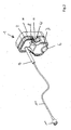
- Figure 1 shows the water trap 1 with a hose 10 and a connection means 11 for the connection with the hose system, whereby a gas-conducting connection from the hose system 300 into the water trap 1 is made possible.
- the water trap 1 is detachably held by a receptacle 30.
- the receptacle 30 can be part of a ventilator or can be attached to the ventilator.
- the ventilator 100 can be designed as a clinical ventilator or as an anesthesia ventilator.
- the ventilator can alternatively also be designed as a home ventilator.
- the respirator 100 has a gas analyzer 200 and a hose system 300, for a gas-conducting connection from the respirator 100 to a patient 90 and to the gas analyzer 200.
- the hose system 300 has a tap 301 to which a water trap 1 is detachably connected, the Water trap 1 has a connection means 11 for connection to the tap 301.
- the connection means 11 merges into a hose 10, which enables a gas-conducting connection from the hose system 300 into the water trap 1.
- the ventilator has a receptacle 30 for the water trap 1, for the non-positive and / or positive connection with the water trap 1, the water trap 1 being connected in a gas-conducting manner to the ventilator and the gas analyzer being connected in a gas-conducting manner to the receptacle 30 and the water trap 1 , wherein the gas analyzer 200 has a suction unit 201, which is set up to convey a defined gas flow from the hose system 300 via the water trap 1 to the gas analyzer 200.
- the suction unit generates a predeterminable negative pressure and thus conveys a gas flow from the hose system 300 via the water trap 1 to the gas analyzer 200, the suction unit having a pressure sensor and / or flow sensor 202 for determining the negative pressure and / or a gas flow.
- the pressure sensor 202 and / or flow sensor is connected to the control unit 120, which triggers an alarm if there is a defined deviation of the vacuum / gas flow from a preset value.
- the ventilator has at least one reader / writer 115 for memory modules 15.
- the water trap has a memory module 15 which stores at least usage data or production data of the water trap.
- the reader / writer 115 recognizes the memory module of the water trap when the water trap is connected to the receptacle 30 and the water trap 1 in a gas-conducting manner.
- the reader / writer 115 activates the suction unit 201 a defined gas flow from the hose system 300 via the water trap 1 to the gas analyzer 200.
- the reader / writer 115 deactivates the suction unit 201.
- the suction unit In order to determine whether the water trap is connected to the receptacle 30 in a gas-conducting manner, the suction unit generates a predeterminable negative pressure and determines the resulting negative pressure and / or the gas flow by sensors. If the vacuum or the gas flow deviates from a specified value, the memory module 15 of the water trap is additionally recognized by the reader / writer 115.
- the memory module 15 of the water trap is recognized alternatively or additionally by the reader / writer 115.
- the suction unit then generates a negative pressure and determines the resulting negative pressure and / or the gas flow by sensors.
- FIG. 2 shows the water trap 1 with a hose 10 and a connection means 11 for the connection with the hose system, whereby a gas-conducting connection from the hose system 300 into the water trap 1 is made possible.
- the water trap 1 is detachably held by a receptacle 30.
- the connection means 11 is preferably non-detachably connected to the hose 10 and the hose 10 is non-detachably connected to the water trap.
- the hose 10 is surrounded in sections by a protective hose 9, the protective hose running at least in sections coaxially with the hose 10.
- the hose and / or the protective hose 9 are positively or materially connected to the water trap 1.
- the water trap has a lower section 7, which forms the water reservoir.
- a wall area of the water trap 1, adjacent to the water reservoir 7, is designed as an extraction point 6. Withdrawal of water, for sample purposes or for emptying, is possible by means of a cannula which is inserted through the sampling point.
- the water trap 1 has spring tabs 4 on both sides, which are complementary to locking means 35 in the region of the receptacle 30. Adjacent to the spring tabs 4, the water trap has recesses 3 that are complementary to the spring tabs 4, the recesses 3 forming the spring space 5 for the spring tabs 4.
- the spring tabs 4 and the latching means 35 have a click noise-generating design, which make the snap-in of the spring tabs 4 audible in the area of the latching means 35.
- FIG. 3 shows the water trap 1 with the hose 10 and the gas-conducting connection through the water trap 1. Adjacent to the confluence of the hose 10 in the. Water trap is arranged at least one filter element 13, which is set up and designed such that a gas flow through the water trap into the gas analyzer occurs at least in one functional state exclusively through the filter element 13.
- the filter element 13 is arranged between the front section 21 and the rear section 22 of the water trap.
- the rear portion 22 of the water trap has at least one nozzle 25 which is complementary to an opening 32 in the receptacle 30.
- a valve 33 allows gas to flow through the intake towards the gas analyzer.
- FIG 4 shows the water trap 1 with the filter elements.
- the rear portion 22 of the water trap has at least one receptacle 23 for filter elements 13, 13 '.
- Flow guide elements 24 for the filter element 13 are provided in the area of the receptacle 23.
- the rear portion 22 of the water trap has at least one nozzle 25 which is complementary to an opening 32 in the receptacle 30.
- two filter elements 13, 13 ' are provided adjacent to the confluence of the hose 10 in the water trap, the filter elements being connected to one another in a gas-conducting manner via a bypass 8 such that when the flow resistance of the first filter element 13 increases, beyond a threshold value, a gas-conducting connection from the hose via the bypass into the second filter element 13 'and to the gas analyzer takes place.
- the receptacle 30 has fastening means 34 for fastening the receptacle to the ventilator.
- the receptacle also has latching means 35, 36 for holding the water trap.
- the openings 32 in the receptacle serve to at least partially accommodate nozzles 25 of the water trap 2.
- the openings have, for example, insertion bevels 31 for the supports.
- the spring tabs 4 of the water trap are located in the region of an indentation 3.
- the spring tabs have control surfaces 14 and a collar 16.
- the latching means 35 have securing elements 36 which, in a functional state, at least partially overlap the collar 16 of the water trap and thus secure the water trap in the receptacle 30.
Landscapes
- Health & Medical Sciences (AREA)
- Life Sciences & Earth Sciences (AREA)
- General Health & Medical Sciences (AREA)
- Public Health (AREA)
- Veterinary Medicine (AREA)
- Biomedical Technology (AREA)
- Heart & Thoracic Surgery (AREA)
- Engineering & Computer Science (AREA)
- Pulmonology (AREA)
- Animal Behavior & Ethology (AREA)
- Hematology (AREA)
- Emergency Medicine (AREA)
- Anesthesiology (AREA)
- Physiology (AREA)
- Physics & Mathematics (AREA)
- Biophysics (AREA)
- Pathology (AREA)
- Medical Informatics (AREA)
- Molecular Biology (AREA)
- Surgery (AREA)
- Sampling And Sample Adjustment (AREA)
- Investigating Or Analysing Biological Materials (AREA)
Abstract
Description
- Diese Erfindung bezieht sich allgemein auf das Gebiet der Beatmungsgeräte, die Atemgas konditionieren.
- Darunter ist beispielsweise eine Anfeuchtung von Atemgas zu verstehen oder auch eine Zumischung von Gasen wie Sauerstoff oder von Narkosegasen. Solche Beatmungsgeräte können in klinischen Anwendungen als Narkose-Beatmungsgerät ausgeführt sein oder in einem heimischen Umfeld als Beatmungsgerät mit Anfeuchtung und/oder Sauerstoffzufuhr.
- Sogenannte Wasserfallen dienen dazu, überschüssige Feuchtigkeit zu entfernen. Beispielsweise werden solche Wasserfallen einem Gasanalysator, der die Anteile der Atemgase oder Narkosegase bestimmen soll, vorgeschaltet.
- Die Einstellung und Einhaltung definierter Vorgabewerte für Atemgase oder Narkosegase oder Feuchtigkeit ist dabei oftmals problematisch.
- Daher wäre ein verbessertes (Narkose-)Beatmungsgerät von Vorteil und insbesondere wäre eine erhöhte Betriebssicherheit und / oder Genauigkeit von Vorteil. Deshalb versuchen Ausführungsformen der vorliegenden Erfindung vorzugsweise, einen oder mehrere Mängel, Nachteile oder Probleme des Standes der Technik, wie beispielsweise die oben genannten, einzeln oder in einer beliebigen Kombination zu verbessern, zu mildern oder zu beseitigen, indem ein Beatmungsgerät, ein Verfahren und eine Vorrichtung bereitgestellt werden gemäß den beigefügten Patentansprüchen.
- Die Erfindung betrifft ein Beatmungsgerät mit einem Gasanalysator und einem Schlauchsystem für eine gasleitende Verbindung von dem Beatmungsgerät zu einem Patienten und zu dem Gasanalysator, dadurch gekennzeichnet, dass das Schlauchsystem einen Abgriff aufweist an den eine Wasserfalle lösbar konnektiert ist, wobei die Wasserfalle ein Anschlussmittel für die Verbindung mit dem Abgriff aufweist, wobei das Anschlussmittel in einen Schlauch übergeht, der eine gasleitende Verbindung von dem Schlauchsystem in die Wasserfalle ermöglicht, wobei der Schlauch mit der Wasserfalle verbunden ist und wobei die Wasserfalle einen vorderen Teilbereich aufweist und einen hinteren Teilbereich aufweist, der dem Beatmungsgerät zugewandt ist, wobei das Beatmungsgerät eine Aufnahme für die Wasserfalle aufweist, zur lösbaren Verbindung mit der Wasserfalle , wobei die Wasserfalle gasleitend mit dem Beatmungsgerät verbunden ist und wobei der Gasanalysator gasleitend mit der Aufnahme und der Wasserfalle verbunden ist, wobei der Gasanalysator eine Saugeinheit aufweist, die eingerichtet ist, einen definierten Gasstrom aus dem Schlauchsystem über die Wasserfalle zu dem Gasanalysator zu fördern.
- Die Erfindung ist auch dadurch gekennzeichnet, dass die Saugeinheit einen vorgebbaren Unterdruck erzeugt und damit einen Gasstrom aus dem Schlauchsystem über die Wasserfalle zu dem Gasanalysator fördert, wobei die Saugeinheit einen Drucksensor und/oder Flusssensor aufweist zur Bestimmung des Unterdruckes und/oder eines Gasflusses.
- Die Erfindung ist auch dadurch gekennzeichnet, dass der Drucksensor, mit der die Steuereinheit verbunden ist, die, bei einer definierten Abweichung des Unterdruckes von einem Vorgabewert, einen Alarm auslöst.
- Die Erfindung ist auch dadurch gekennzeichnet, dass der Flusssensor, mit dem die Steuereinheit verbunden ist, die, bei einer definierten Abweichung des Gasflusses von einem Vorgabewert, einen Alarm auslöst.
- Die Erfindung ist auch dadurch gekennzeichnet, dass das Beatmungsgerät zumindest einen Lese-/Schreibgerät für Speicherbausteine aufweist.
- Die Erfindung ist auch dadurch gekennzeichnet, dass die Wasserfalle eingerichtet und ausgebildet ist, lösbar mit einer Aufnahme des Beatmungsgerätes und lösbar mit dem Schlauchsystem verbunden zu werden.
- Die Erfindung betrifft auch eine Wasserfalle zur Verwendung mit einem Beatmungsgerät, wobei das Anschlussmittel unlösbar mit dem Schlauch verbunden ist und der Schlauch unlösbar mit der Wasserfalle verbunden ist.
- Die Erfindung ist auch dadurch gekennzeichnet, dass der Schlauch zumindest abschnittsweise von einem Schutzschlauch umgeben ist, wobei der Schutzschlauch zumindest abschnittsweise koaxial zu dem Schlauch verläuft.
- Die Erfindung ist auch dadurch gekennzeichnet, dass der Schutzschlauch unlösbar mit der Wasserfalle verbunden ist.
- Die Erfindung ist auch dadurch gekennzeichnet, dass der Schutzschlauch formschlüssig oder stoffschlüssig mit der Wasserfalle verbunden ist.
- Die Erfindung ist auch dadurch gekennzeichnet, dass die Wasserfalle einen unteren Teilbereich aufweist, der das Wasserreservoir bildet.
- Die Erfindung ist auch dadurch gekennzeichnet, dass der untere Teilbereich eine Entnahmestelle aufweist, für die Entnahme von Wasser aus dem Reservoir mittels einer Kanüle.
- Die Erfindung ist auch dadurch gekennzeichnet, dass die Wasserfalle, benachbart zu der Einmündung des Schlauches in die Wasserfalle, zumindest ein Filterelement aufweist, welches so eingerichtet und ausgebildet ist, dass eine Gasströmung durch die Wasserfalle in den Gasanalysator zumindest in einem Funktionszustand ausschließlich durch das Filterelement erfolgt.
- Die Erfindung ist auch dadurch gekennzeichnet, dass das Filterelement zwischen dem vorderen Teilbereich und dem hinteren Teilbereich der Wasserfalle angeordnet ist.
- Die Erfindung ist auch dadurch gekennzeichnet, dass der hintere Teilbereich der Wasserfalle zumindest eine Aufnahme für das Filterelement aufweist.
- Die Erfindung ist auch dadurch gekennzeichnet, dass der hintere Teilbereich der Wasserfalle im Bereich der Aufnahme Strömungsleitelemente für das Filterelement aufweist.
- Die Erfindung ist auch dadurch gekennzeichnet, dass der hintere Teilbereich der Wasserfalle zumindest einen Stutzen aufweist, der komplementär zu einer Öffnung in der Aufnahme ausgeführt ist.
- Die Erfindung ist auch dadurch gekennzeichnet, dass der hintere Teilbereich der Wasserfalle zumindest einen Stutzen aufweist, der komplementär zu einer Öffnung in der Aufnahme ausgeführt ist.
- Die Erfindung ist auch dadurch gekennzeichnet, dass die Wasserfalle, benachbart zu der Einmündung des Schlauches in die Wasserfalle, zumindest ein Filterelement und benachbart dazu ein zweites Filterelement aufweist, wobei die Filterelemente, beispielsweise über einen Bypass, derart gasleitend miteinander verbunden sind, dass bei Zunahme des Strömungswiderstandes des ersten Filterelementes , über einen Schwellenwert hinaus, eine gasleitende Verbindung von dem Schlauch über den Bypass in das zweite Filterelement und zu dem Gasanalysator erfolgt.
- Die Erfindung ist auch dadurch gekennzeichnet, dass die Wasserfalle einen Speicherbaustein aufweist, der zumindest Nutzungsdaten oder Herstellungsdaten der Wasserfalle speichert.
- Die Erfindung ist auch dadurch gekennzeichnet, dass die Wasserfalle beidseitige Federlaschen aufweist die komplementär zu Rastmitteln im Bereich der Aufnahme ausgebildet sind.
- Die Erfindung ist auch dadurch gekennzeichnet, dass die Federlaschen Bedienflächen und einen Kragen aufweisen.
- Die Erfindung ist auch dadurch gekennzeichnet, dass die Rastmittel Sicherungselemente aufweisen, die in einem Funktionszustand zumindest teilweise den Kragen überlappen und somit sichern.
- Die Erfindung ist auch dadurch gekennzeichnet, dass die Wasserfalle benachbart zu dem Federlaschen Aussparungen aufweist die komplementär zu den Federlaschen ausgebildet sind, wobei die Aussparungen den Federraum für die Federlaschen bilden.
- Die Erfindung ist auch dadurch gekennzeichnet, dass die Federlaschen und die Rastmittel eine Klick-Geräusch generierende Gestaltung aufweisen, die ein Einrasten der Federlaschen im Bereich der Rastmittel akustisch wahrnehmbar machen.
- Die Erfindung betrifft auch eine Aufnahme für die Wasserfalle nach zumindest einem der vorhergehenden Ansprüche dadurch gekennzeichnet, dass die Aufnahme Befestigungsmittel aufweist zur Befestigung an dem Beatmungsgerät, wobei die Aufnahme Rastmittel, aufweist zur Halterung der Wasserfalle, wobei die Aufnahme Öffnungen aufweist, die der zumindest teilweisen Aufnahme von Stutzen der Wasserfalle dienen.
- Die Erfindung betrifft auch ein Verfahren zur Analyse von Beatmungsgas umfassend ein Beatmungsgerät mit einem Gasanalysator und einem Schlauchsystem, für eine gasleitende Verbindung von dem Beatmungsgerät zu einem Patienten und zu dem Gasanalysator, dadurch gekennzeichnet, dass das Schlauchsystem einen Abgriff aufweist an den eine Wasserfalle lösbar konnektiert ist, wobei die Wasserfalle ein Anschlussmittel für die Verbindung mit dem Abgriff aufweist, wobei das Anschlussmittel in einen Schlauch übergeht, der eine gasleitende Verbindung von dem Schlauchsystem in die Wasserfalle ermöglicht, wobei der Schlauch mit der Wasserfalle verbunden ist und wobei die Wasserfalle einen vorderen Teilbereich ausweist und einen hinteren Teilbereich aufweist, der dem Beatmungsgerät zugewandt ist, wobei das Beatmungsgerät eine Aufnahme für die Wasserfalle aufweist, zur lösbaren Verbindung mit der Wasserfalle, wobei die Wasserfalle gasleitend mit dem Beatmungsgerät verbunden ist und wobei der Gasanalysator gasleitend mit der Aufnahme und der Wasserfalle verbunden ist, wobei der Gasanalysator eine Saugeinheit aufweist, die eingerichtet ist, einen definierten Gasstrom aus dem Schlauchsystem über die Wasserfalle zu dem Gasanalysator zu fördern.
- Die Erfindung ist auch dadurch gekennzeichnet, dass die Saugeinheit einen vorgebbaren Unterdruck erzeugt und damit einen Gasstrom aus dem Schlauchsystem über die Wasserfalle zu dem Gasanalysator fördert, wobei die Saugeinheit einen Drucksensor und/oder Flusssensor aufweist zur Bestimmung des Unterdruckes und/oder eines Gasflusses.
- Die Erfindung ist auch dadurch gekennzeichnet, dass der Drucksensor, mit der die Steuereinheit verbunden ist, die, bei einer definierten Abweichung des Unterdruckes von einem Vorgabewert, einen Alarm auslöst.
- Die Erfindung ist auch dadurch gekennzeichnet, dass der Flusssensor, mit dem die Steuereinheit verbunden ist, die, bei einer definierten Abweichung des Gasflusses von einem Vorgabewert, einen Alarm auslöst.
- Die Erfindung ist auch dadurch gekennzeichnet, dass das Beatmungsgerät zumindest einen Lese-/Schreibgerät für Speicherbausteine aufweist, wobei zumindest ein Speicherbaustein in der Wasserfalle angeordnet ist und wobei das Lese-/Schreibgerät den Speicherbaustein der Wasserfalle dann erkennt, wenn die Wasserfalle gasleitend mit der Aufnahme und der Wasserfalle verbunden ist.
- Die Erfindung ist auch dadurch gekennzeichnet, dass das Beatmungsgerät zumindest einen Lese-/Schreibgerät für Speicherbausteine aufweist, wobei zumindest ein Speicherbaustein in der Wasserfalle angeordnet ist und wobei das Lese-/Schreibgerät den Speicherbaustein der Wasserfalle dann erkennt, wenn die Wasserfalle gasleitend mit der Aufnahme verbunden ist.
- Die Erfindung ist auch dadurch gekennzeichnet, dass das Lese-/Schreibgerät eingerichtet und ausgebildet ist den Speicherbaustein der Wasserfalle zu erkennen und bei Erkennung eine Änderung der Funktionsweise von Saugeinheit und/oder Gasanalysator und/oder Gerät veranlasst.
- Die Erfindung ist auch dadurch gekennzeichnet, dass das Lese-/Schreibgerät bei Erkennung des Speicherbausteins der Wasserfalle die Saugeinheit aktiviert einen definierten Gasstrom aus dem Schlauchsystem über die Wasserfalle zu dem Gasanalysator zu fördern.
- Die Erfindung ist auch dadurch gekennzeichnet, dass das Lese-/Schreibgerät bei Nicht-Erkennung des Speicherbausteins der Wasserfalle die Saugeinheit deaktiviert.
- Die Erfindung ist auch dadurch gekennzeichnet, dass zur Ermittlung ob die Wasserfalle gasleitend mit der Aufnahme verbunden ist die Saugeinheit einen vorgebbaren Unterdruck erzeugt und sensorisch den resultierenden Unterdruck und/oder den Gasfluss bestimmt und bei einer definierten Abweichung des Unterdruckes oder des Gasflusses von einem Vorgabewert zusätzlich eine Erkennung des Speicherbausteins der Wasserfalle durch das Lese-/Schreibgerät durchgeführt wird.
- Die Erfindung ist auch dadurch gekennzeichnet, dass zur Ermittlung ob die Wasserfalle gasleitend mit der Aufnahme verbunden ist eine Erkennung des Speicherbausteins der Wasserfalle durch das Lese-/Schreibgerät durchgeführt wird und dann die Saugeinheit einen vorgebbaren Unterdruck erzeugt und sensorisch den resultierenden Unterdruck und/oder den Gasfluss bestimmt.
- Gemäß einem Aspekt der Erfindung wird ein Beatmungsgerät bereitgestellt mit einem Gasanalysator und einem Schlauchsystem, für eine gasleitende Verbindung von dem Beatmungsgerät zu einem Patienten und zu dem Gasanalysator wobei das Schlauchsystem einen Abgriff aufweist an den eine Wasserfalle lösbar konnektiert ist, wobei die Wasserfalle ein Anschlussmittel für die Verbindung mit dem Abgriff aufweist, wobei das Anschlussmittel in einen Schlauch übergeht, der eine gasleitende Verbindung von dem Schlauchsystem in die Wasserfalle ermöglicht, wobei der Schlauch mit der Wasserfalle verbunden ist und wobei die Wasserfalle einen vorderen Teilbereich ausweist und einen hinteren Teilbereich aufweist, der dem Beatmungsgerät zugewandt ist, wobei das Beatmungsgerät eine Aufnahme für die Wasserfalle aufweist, zur lösbaren Verbindung mit der Wasserfalle, wobei die Wasserfalle gasleitend mit dem Beatmungsgerät verbunden ist und wobei der Gasanalysator gasleitend mit der Aufnahme und der Wasserfalle verbunden ist, wobei der Gasanalysator eine Saugeinheit aufweist, die eingerichtet ist, einen definierten Gasstrom aus dem Schlauchsystem über die Wasserfalle zu dem Gasanalysator zu fördern.
- Gemäß noch einem weiteren Aspekt der Erfindung wird eine Wasserfalle zur Verwendung mit einem Beatmungsgerät bereitgestellt. Wobei die Wasserfalle eingerichtet und ausgebildet ist, lösbar mit einer Aufnahme des Beatmungsgerätes und lösbar mit dem Schlauchsystem verbunden zu werden.
- Gemäß noch einem weiteren Aspekt der Erfindung wird ein Verfahren bereitgestellt. Das Verfahren dient zur Analyse von Beatmungsgas und umfasst ein Beatmungsgerät mit einem Gasanalysator und einem Schlauchsystem, für eine gasleitende Verbindung von dem Beatmungsgerät zu einem Patienten und zu dem Gasanalysator, wobei das Schlauchsystem einen Abgriff für eine Wasserfalle aufweist, wobei die Wasserfalle ein Anschlussmittel für die Verbindung mit dem Abgriff aufweist, wobei das Anschlussmittel in einen Schlauch übergeht, der eine gasleitende Verbindung von dem Schlauchsystem in die Wasserfalle ermöglicht, wobei der Schlauch mit der Wasserfalle verbunden ist und wobei die Wasserfalle einen vorderen Teilbereich ausweist und einen hinteren Teilbereich aufweist, der dem Beatmungsgerät zugewandt ist, wobei das Beatmungsgerät eine Aufnahme für die Wasserfalle aufweist, zur lösbaren Verbindung mit der Wasserfalle, wobei die Wasserfalle gasleitend mit dem Beatmungsgerät verbunden ist und wobei der Gasanalysator gasleitend mit der Aufnahme und der Wasserfalle verbunden ist, wobei der Gasanalysator eine Saugeinheit aufweist, die eingerichtet ist, einen definierten Gasstrom aus dem Schlauchsystem über die Wasserfalle zu dem Gasanalysator zu fördern.
- Gemäß noch einem weiteren Aspekt der Erfindung wird ein weiteres Verfahren bereitgestellt. Dieses Verfahren ist dadurch gekennzeichnet, dass ein Lese-/Schreibgerät des Beatmungsgerätes eingerichtet und ausgebildet ist den Speicherbaustein der Wasserfalle zu erkennen und bei Erkennung eine Änderung der Funktionsweise von Saugeinheit und/oder Gasanalysator und/oder Beatmungsgerät zu veranlassen.
-
Figur 1 zeigt die Wasserfalle 1 mit einem Schlauch 10 und einem Anschlussmittel 11 für die Verbindung mit dem Schlauchsystem, womit eine gasleitende Verbindung von dem Schlauchsystem 300 in die Wasserfalle 1 ermöglicht wird. Die Wasserfalle 1 wird von einer Aufnahme 30 lösbar gehalten. Die Aufnahme 30 kann Teil eines Beatmungsgerätes sein oder an das Beatmungsgerät angefügt werden. Das Beatmungsgerät 100 kann als klinisches Beatmungsgerät oder als Anästhesie-Beatmungsgerät ausgeführt sein. Das Beatmungsgerät kann alternativ auch als Heimbeatmungsgerät ausgeführt sein. - Das Beatmungsgerät 100 weist einen Gasanalysator 200 und ein Schlauchsystem 300 auf, für eine gasleitende Verbindung von dem Beatmungsgerät 100 zu einem Patienten 90 und zu dem Gasanalysator 200. Das Schlauchsystem 300 weist einen Abgriff 301 auf an den eine Wasserfalle 1 lösbar konnektiert ist, wobei die Wasserfalle 1 ein Anschlussmittel 11 für die Verbindung mit dem Abgriff 301 aufweist. Das Anschlussmittel 11 geht in einen Schlauch 10 über, der eine gasleitende Verbindung von dem Schlauchsystem 300 in die Wasserfalle 1 ermöglicht. Das Beatmungsgerät weist eine Aufnahme 30 für die Wasserfalle 1 auf, zur kraftschlüssigen und/oder formschlüssigen lösbaren Verbindung mit der Wasserfalle 1, wobei die Wasserfalle 1 gasleitend mit dem Beatmungsgerät verbunden ist und wobei der Gasanalysator gasleitend mit der Aufnahme 30 und der Wasserfalle 1 verbunden ist, wobei der Gasanalysator 200 eine Saugeinheit 201 aufweist, die eingerichtet ist, einen definierten Gasstrom aus dem Schlauchsystem 300 über die Wasserfalle 1 zu dem Gasanalysator 200 zu fördern.
- Die Saugeinheit erzeugt einen vorgebbaren Unterdruck und fördert damit einen Gasstrom aus dem Schlauchsystem 300 über die Wasserfalle 1 zu dem Gasanalysator 200, wobei die Saugeinheit einen Drucksensor und/oder Flusssensor 202 aufweist zur Bestimmung des Unterdruckes und/oder eines Gasflusses.
- Der Drucksensor 202 und/oder Flusssensor ist mit der Steuereinheit 120 verbunden die, bei einer definierten Abweichung des Unterdruckes/Gasflusses von einem Vorgabewert, einen Alarm auslöst.
- Das Beatmungsgerät weist zumindest ein Lese-/Schreibgerät 115 für Speicherbausteine 15 auf. Die Wasserfalle weist einen Speicherbaustein 15 auf, der zumindest Nutzungsdaten oder Herstellungsdaten der Wasserfalle speichert.
- Das Lese-/Schreibgerät 115 erkennt den Speicherbaustein der Wasserfalle dann, wenn die Wasserfalle gasleitend mit der Aufnahme 30 und der Wasserfalle 1 verbunden ist.
- Bei Erkennung des Speicherbausteins 15 der Wasserfalle aktiviert das Lese-/Schreibgerät 115 die Saugeinheit 201 einen definierten Gasstrom aus dem Schlauchsystem 300 über die Wasserfalle 1 zu dem Gasanalysator 200.
- Das Lese-/Schreibgerät 115 deaktiviert bei Nicht-Erkennung des Speicherbausteins 15 der Wasserfalle die Saugeinheit 201.
- Zur Ermittlung ob die Wasserfalle gasleitend mit der Aufnahme 30 verbunden ist, erzeugt die Saugeinheit einen vorgebbaren Unterdruck und bestimmt sensorisch den resultierenden Unterdruck und/oder den Gasfluss. Bei einer definierten Abweichung des Unterdruckes oder des Gasflusses von einem Vorgabewert wird zusätzlich eine Erkennung des Speicherbausteins 15 der Wasserfalle durch das Lese-/Schreibgerät 115 durchgeführt.
- Zur Ermittlung ob die Wasserfalle gasleitend mit der Aufnahme 30 verbunden ist erfolgt alternativ oder ergänzend eine Erkennung des Speicherbausteins 15 der Wasserfalle durch das Lese-/Schreibgerät 115. Daraufhin erzeugt die Saugeinheit einen Unterdruck und bestimmt sensorisch den resultierenden Unterdruck und/oder den Gasfluss.
-
Figur 2 zeigt die Wasserfalle 1 mit einem Schlauch 10 und einem Anschlussmittel 11 für die Verbindung mit dem Schlauchsystem, womit eine gasleitende Verbindung von dem Schlauchsystem 300 in die Wasserfalle 1 ermöglicht wird. Die Wasserfalle 1 wird von einer Aufnahme 30 lösbar gehalten. Das Anschlussmittel 11 ist bevorzugt unlösbar mit dem Schlauch 10 verbunden ist und der Schlauch 10 ist unlösbar mit der Wasserfalle verbunden. - Der Schlauch 10 ist abschnittsweise von einem Schutzschlauch 9 umgeben, wobei der Schutzschlauch zumindest abschnittsweise koaxial zu dem Schlauch 10 verläuft. Der Schlauch und/oder der Schutzschlauch 9 sind formschlüssig oder stoffschlüssig mit der Wasserfalle 1 verbunden.
- Die Wasserfalle weist einen unteren Teilbereich 7 auf, der das Wasserreservoir bildet. Ein Wandbereich der Wasserfalle 1, benachbart zu dem Wasserreservoir 7, ist als eine Entnahmestelle 6 ausgebildet. Eine Entnahme von Wasser, für Probenzwecke oder für die Entleerung, ist mittels einer Kanüle möglich, die durch die Entnahmestelle eingestochen wird.
- Die Wasserfalle 1 weist beidseitige Federlaschen 4 auf, die komplementär zu Rastmitteln 35 im Bereich der Aufnahme 30 ausgebildet sind. Benachbart zu dem Federlaschen 4 weist die Wasserfalle Aussparungen 3 auf, die komplementär zu den Federlaschen 4 ausgebildet sind, wobei die Aussparungen 3 den Federraum 5 für die Federlaschen 4 bilden.
- Die Federlaschen 4 und die Rastmitteln 35 weisen eine Klick-Geräusch generierende Gestaltung auf, die ein Einrasten der Federlaschen 4 im Bereich der Rastmittel 35 akustisch wahrnehmbar machen.
-
Figur 3 zeigt die Wasserfalle 1 mit dem Schlauch 10 und die gasleitende Verbindung durch die Wasserfalle 1. Benachbart zu der Einmündung des Schlauches 10 in die. Wasserfalle ist zumindest ein Filterelement 13 angeordnet, welches so eingerichtet und ausgebildet ist, dass eine Gasströmung durch die Wasserfalle in den Gasanalysator zumindest in einem Funktionszustand ausschließlich durch das Filterelement 13 erfolgt. - Das Filterelement 13 ist zwischen dem vorderen Teilbereich 21 und dem hinteren Teilbereich 22 der Wasserfalle angeordnet.
- Der hintere Teilbereich 22 der Wasserfalle weist zumindest einen Stutzen 25 auf, der komplementär zu einer Öffnung 32 in der Aufnahme 30 ausgeführt ist. Ein Ventil 33.ermöglicht den Durchfluss von Gas durch die Aufnahme in Richtung des Gasanalysators.
-
Figur 4 zeigt die Wasserfalle 1 mit den Filterelementen. Der hintere Teilbereich 22 der Wasserfalle weist zumindest eine Aufnahme 23 für Filterelemente 13, 13' auf. Im Bereich der Aufnahme 23 sind Strömungsleitelemente 24 für das Filterelement 13 vorgesehen. - Der hintere Teilbereich 22 der Wasserfalle weist zumindest einen Stutzen 25 auf, der komplementär zu einer Öffnung 32 in der Aufnahme 30 ausgeführt ist.
- Aus den
Figuren 2 und4 wird deutlich: Benachbart zu der Einmündung des Schlauches 10 in die Wasserfalle sind zwei Filterelemente 13, 13' vorgesehen, wobei die Filterelemente über einen Bypass 8 derart gasleitend miteinander verbunden sind, dass bei Zunahme des Strömungswiderstandes des ersten Filterelementes 13, über einen Schwellenwert hinaus, eine gasleitende Verbindung von dem Schlauch über den Bypass in das zweite Filterelement 13' und zu dem Gasanalysator erfolgt. - Aus den
Figuren 5 und6 wird deutlich: Die Aufnahme 30 weist Befestigungsmittel 34 auf zur Befestigung der Aufnahme an dem Beatmungsgerät. Die Aufnahme weist zudem Rastmittel 35, 36 auf zur Halterung der Wasserfalle. Die Öffnungen 32 in der Aufnahme dienen der zumindest teilweisen Aufnahme von Stutzen 25 der Wasserfalle 2. Die Öffnungen weisen beispielsweise Einführschrägen 31 für die Stützen auf. - Die Federlaschen 4 der Wasserfalle befinden sich im Bereich einer Einbuchtung 3. Die Federlaschen weisen Bedienflächen 14 und einen Kragen 16 auf.
- Die Rastmittel 35 weisen Sicherungselemente 36 auf, die in einem Funktionszustand zumindest teilweise den Kragen 16 der Wasserfalle überlappen und somit die Wasserfalle in der Aufnahme 30 sichern.
Claims (16)
- Beatmungsgerät 100 mit einem Gasanalysator 200 und einem Schlauchsystem 300, für eine gasleitende Verbindung von dem Beatmungsgerät 100 zu einem Patienten 90 und zu dem Gasanalysator 200, dadurch gekennzeichnet, dass das Schlauchsystem 300 einen Abgriff 301 aufweist an den eine Wasserfalle 1 lösbar konnektiert ist, wobei die Wasserfalle 1 ein Anschlussmittel 11 für die Verbindung mit dem Abgriff 301 aufweist, wobei das Anschlussmittel 11 in einen Schlauch 10 übergeht, der eine gasleitende Verbindung von dem Schlauchsystem 300 in die Wasserfalle 1 ermöglicht, wobei der Schlauch mit der Wasserfalle 1 verbunden ist und wobei die Wasserfalle einen vorderen Teilbereich aufweist 21 und einen hinteren Teilbereich 22 aufweist, der dem Beatmungsgerät 100 zugewandt ist, wobei das Beatmungsgerät eine Aufnahme 30 für die Wasserfalle 1 aufweist, zur lösbaren Verbindung mit der Wasserfalle 1, wobei die Wasserfalle 1 gasleitend mit dem Beatmungsgerät verbunden ist und wobei der Gasanalysator gasleitend mit der Aufnahme 30 und der Wasserfalle 1 verbunden ist, wobei der Gasanalysator 200 eine Saugeinheit 201 aufweist, die eingerichtet ist, einen definierten Gasstrom aus dem Schlauchsystem 300 über die Wasserfalle 1 zu dem Gasanalysator 200 zu fördern.
- Beatmungsgerät nach zumindest einem der vorhergehenden Ansprüche dadurch gekennzeichnet, dass die Saugeinheit einen vorgebbaren Unterdruck erzeugt und damit einen Gasstrom aus dem Schlauchsystem 300 über die Wasserfalle 1 zu dem Gasanalysator 200 fördert, wobei die Saugeinheit einen Drucksensor und/oder Flusssensor 202 aufweist zur Bestimmung des Unterdruckes und/oder eines Gasflusses.
- Beatmungsgerät nach zumindest einem der vorhergehenden Ansprüche dadurch gekennzeichnet, dass der Drucksensor 202 und/oder der Flusssensor, mit der Steuereinheit 120 verbunden sind, wobei die Steuereinheit 120, bei einer definierten Abweichung des Unterdruckes von einem Vorgabewert, einen Alarm auslöst.
- Beatmungsgerät nach zumindest einem der vorhergehenden Ansprüche dadurch gekennzeichnet, dass das Beatmungsgerät zumindest einen Lese-/Schreibgerät 115 für Speicherbausteine 15 aufweist.
- Wasserfalle 1 zur Verwendung mit einem Beatmungsgerät nach Anspruch 1 dadurch gekennzeichnet, dass die Wasserfalle eingerichtet und ausgebildet ist lösbar mit einer Aufnahme 30 des Beatmungsgerätes und lösbar mit dem Schlauchsystem verbunden zu werden.
- Wasserfalle zur Verwendung mit einem Beatmungsgerät nach Anspruch 1 dadurch gekennzeichnet, dass das Anschlussmittel 11 unlösbar mit dem Schlauch 10 verbunden ist und der Schlauch 10 unlösbar mit der Wasserfalle verbunden ist.
- Wasserfalle nach zumindest einem der vorhergehenden Ansprüche dadurch gekennzeichnet, dass der Schlauch 10 zumindest abschnittsweise von einem Schutzschlauch 9 umgeben ist, wobei der Schutzschlauch zumindest abschnittsweise koaxial zu dem Schlauch 10 verläuft.
- Wasserfalle nach zumindest einem der vorhergehenden Ansprüche dadurch gekennzeichnet, dass die Wasserfalle einen unteren Teilbereich 7 aufweist, der das Wasserreservoir bildet, wobei der untere Teilbereich 7 eine Entnahmestelle 6 aufweist, für die Entnahme von Wasser aus dem Reservoir mittels einer Kanüle.
- Wasserfalle nach zumindest einem der vorhergehenden Ansprüche dadurch gekennzeichnet, dass die Wasserfalle, benachbart zu der Einmündung des Schlauches 10 in die Wasserfalle, zumindest ein Filterelement 13 aufweist, welches so eingerichtet und ausgebildet ist, dass eine Gasströmung durch die Wasserfalle in den Gasanalysator zumindest in einem Funktionszustand ausschließlich durch das Filterelement 13 erfolgt.
- Wasserfalle nach zumindest einem der vorhergehenden Ansprüche dadurch gekennzeichnet, dass die Wasserfalle, benachbart zu der Einmündung des Schlauches 10 in die Wasserfalle, zumindest ein Filterelement 13 und benachbart dazu ein zweites Filterelement 13' aufweist, wobei die Filterelemente, beispielsweise über einen Bypass 8, derart gasleitend miteinander verbunden sind, dass bei Zunahme des Strömungswiderstandes des ersten Filterelementes 13, über einen Schwellenwert hinaus, eine gasleitende Verbindung von dem Schlauch über den Bypass in das zweite Filterelement 13' und zu dem Gasanalysator erfolgt.
- Wasserfalle zur Verwendung mit einem Beatmungsgerät nach Anspruch 1 dadurch gekennzeichnet, dass die Wasserfalle einen Speicherbaustein 15 aufweist, der zumindest Nutzungsdaten oder Herstellungsdaten der Wasserfalle speichert.
- Wasserfalle nach zumindest einem der vorhergehenden Ansprüche dadurch gekennzeichnet, dass die Wasserfalle beidseitige Federlaschen 4 aufweist die komplementär zu Rastmitteln 35 im Bereich der Aufnahme 30 ausgebildet sind, wobei die Wasserfalle benachbart zu den Federlaschen 4 Aussparungen 3 aufweist, die komplementär zu den Federlaschen 4 ausgebildet sind, wobei die Aussparungen 3 den Federraum 5 für die Federlaschen 4 bilden.
- Wasserfalle nach zumindest einem der vorhergehenden Ansprüche dadurch gekennzeichnet, dass die Federlaschen 4 Bedienflächen 14 und einen Kragen 16 aufweisen, wobei die Rastmittel 35 Sicherungselemente 36 aufweisen, die in einem Funktionszustand zumindest teilweise den Kragen überlappen und somit sichern.
- Wasserfalle nach zumindest einem der vorhergehenden Ansprüche dadurch gekennzeichnet, dass die Federlaschen 4 und die Rastmitteln 35 eine Klick-Geräusch generierende Gestaltung aufweisen, die ein Einrasten der Federlaschen 4 im Bereich der Rastmittel 35 akustisch wahrnehmbar machen.
- Aufnahme 30 für die Wasserfalle 1 nach zumindest einem der vorhergehenden Ansprüche dadurch gekennzeichnet, dass die Aufnahme 30 Befestigungsmittel 34 aufweist zur Befestigung an dem Beatmungsgerät, wobei die Aufnahme Rastmittel 35, 36 aufweist zur Halterung der Wasserfalle, wobei die Aufnahme 30 Öffnungen 32 aufweist, die der zumindest teilweisen Aufnahme von Stutzen 25 der Wasserfalle 2 dienen.
- Verfahren zur Analyse von Beatmungsgas umfassend ein Beatmungsgerät 100 mit einem Gasanalysator 200 und einem Schlauchsystem 300, für eine gasleitende Verbindung von dem Beatmungsgerät 100 zu einem Patienten 90 und zu dem Gasanalysator 200, dadurch gekennzeichnet, dass das Schlauchsystem 300 einen Abgriff 301 aufweist an den eine Wasserfalle 1 lösbar konnektiert ist, wobei die Wasserfalle 1 ein Anschlussmittel 11 für die Verbindung mit dem Abgriff 301 aufweist, wobei das Anschtussmittel 11 in einen Schlauch 10 übergeht, der eine gasleitende Verbindung von dem Schlauchsystem 300 in die Wasserfalle 1 ermöglicht, wobei der Schlauch mit der Wasserfalle 1 verbunden ist und wobei die Wasserfalle einen vorderen Teilbereich ausweist 21 und einen hinteren Teilbereich 22 aufweist, der dem Beatmungsgerät 100 zugewandt ist, wobei das Beatmungsgerät eine Aufnahme 30 für die Wasserfalle 1 aufweist, zur lösbaren Verbindung mit der Wasserfalle 1, wobei die Wasserfalle 1 gasleitend mit dem Beatmungsgerät verbunden ist und wobei der Gasanalysator gasleitend mit der Aufnahme 30 und der Wasserfalle 1 verbunden ist, wobei der Gasanalysator 200 eine Saugeinheit 201 aufweist, die eingerichtet ist, einen definierten Gasstrom aus dem Schlauchsystem 300 über die Wasserfalle 1 zu dem Gasanalysator 200 zu fördern.
Applications Claiming Priority (1)
| Application Number | Priority Date | Filing Date | Title |
|---|---|---|---|
| DE102018008729 | 2018-11-07 |
Publications (2)
| Publication Number | Publication Date |
|---|---|
| EP3649936A1 true EP3649936A1 (de) | 2020-05-13 |
| EP3649936B1 EP3649936B1 (de) | 2023-03-29 |
Family
ID=68501315
Family Applications (1)
| Application Number | Title | Priority Date | Filing Date |
|---|---|---|---|
| EP19000509.0A Active EP3649936B1 (de) | 2018-11-07 | 2019-11-06 | Wasserfalle für ein beatmungsgerät und beatmungsgerät mit wasserfalle |
Country Status (2)
| Country | Link |
|---|---|
| EP (1) | EP3649936B1 (de) |
| DE (1) | DE102019129213A1 (de) |
Citations (6)
| Publication number | Priority date | Publication date | Assignee | Title |
|---|---|---|---|---|
| US20080119754A1 (en) * | 2006-11-22 | 2008-05-22 | Mika Hietala | Method and Arrangement for Measuring Breath Gases of a Patient |
| US7940175B2 (en) * | 2006-12-09 | 2011-05-10 | Dräger Medical GmbH | Device with a detectably designed water trap and process for detecting a water trap |
| EP2457506A1 (de) * | 2010-11-26 | 2012-05-30 | General Electric Company | Flüssigkeitstrennvorrichtung zum Entfernen einer Flüssigkeit aus einem Atemgas und Atemgas-Analysesystem |
| WO2012094008A1 (en) * | 2011-01-06 | 2012-07-12 | Ikaria, Inc. | Gas delivery device and system |
| WO2014027290A1 (en) * | 2012-08-15 | 2014-02-20 | Koninklijke Philips N.V. | Sidestream respiratory gas sampling system with flexible accessories and removable water trap |
| DE102012220565A1 (de) * | 2012-11-12 | 2014-03-27 | Bluepoint Medical Gmbh & Co. Kg | Gasprobenleitung und Gasanalysesystem |
Family Cites Families (1)
| Publication number | Priority date | Publication date | Assignee | Title |
|---|---|---|---|---|
| DE19901590C1 (de) * | 1999-01-16 | 2000-07-27 | Draeger Medizintech Gmbh | Wasserfalle für einen Probengasstrom |
-
2019
- 2019-10-29 DE DE102019129213.1A patent/DE102019129213A1/de active Pending
- 2019-11-06 EP EP19000509.0A patent/EP3649936B1/de active Active
Patent Citations (6)
| Publication number | Priority date | Publication date | Assignee | Title |
|---|---|---|---|---|
| US20080119754A1 (en) * | 2006-11-22 | 2008-05-22 | Mika Hietala | Method and Arrangement for Measuring Breath Gases of a Patient |
| US7940175B2 (en) * | 2006-12-09 | 2011-05-10 | Dräger Medical GmbH | Device with a detectably designed water trap and process for detecting a water trap |
| EP2457506A1 (de) * | 2010-11-26 | 2012-05-30 | General Electric Company | Flüssigkeitstrennvorrichtung zum Entfernen einer Flüssigkeit aus einem Atemgas und Atemgas-Analysesystem |
| WO2012094008A1 (en) * | 2011-01-06 | 2012-07-12 | Ikaria, Inc. | Gas delivery device and system |
| WO2014027290A1 (en) * | 2012-08-15 | 2014-02-20 | Koninklijke Philips N.V. | Sidestream respiratory gas sampling system with flexible accessories and removable water trap |
| DE102012220565A1 (de) * | 2012-11-12 | 2014-03-27 | Bluepoint Medical Gmbh & Co. Kg | Gasprobenleitung und Gasanalysesystem |
Also Published As
| Publication number | Publication date |
|---|---|
| EP3649936B1 (de) | 2023-03-29 |
| DE102019129213A1 (de) | 2020-05-07 |
Similar Documents
| Publication | Publication Date | Title |
|---|---|---|
| EP0891199B1 (de) | Vorrichtung und verfahren zur überwachung von atemkennwerten eines beatmungssystems | |
| DE19903732B4 (de) | Vorrichtung zur Beatmung sowie Verfahren zur Aufbereitung eines Beatmungsgases | |
| DE102007039391B4 (de) | Beatmungsanfeuchter | |
| DE69916907T2 (de) | Mund- / Nasenkanüle | |
| DE3423140A1 (de) | Stroemungsabschwaecher | |
| DE60300172T2 (de) | Vorrichtung und Methode zur Messung von Atemalkohol | |
| WO2008106961A2 (de) | Transportabler pneumotachograph zur messung von bestandteilen des exspirationsvolumens sowie ein verfahren hierzu | |
| EP3352812B1 (de) | Bestimmung in blut gelöster gase im extrakorporalen kreislauf | |
| EP1779887B1 (de) | Schlauchset | |
| EP3957347B1 (de) | Beatmungsgerät für high-flow-sauerstofftherapie | |
| DE102021124785A1 (de) | Durchflusssensor | |
| DE102009048405A1 (de) | Regeleinrichtung für Gasbrenner | |
| DE102018003026A1 (de) | Beatmungsvorrichtung mit einem Sicherheitsventil | |
| EP4349388B1 (de) | Vorrichtung und verfahren zur detektion eines lecks während einer künstlichen beatmung | |
| DE102016007336A1 (de) | Medizintechnische Vorrichtung und Verfahren zur Alarmorganisation | |
| EP3649936B1 (de) | Wasserfalle für ein beatmungsgerät und beatmungsgerät mit wasserfalle | |
| DE102009015928B4 (de) | Vorrichtung zur Anreicherung von Atemgas mit Sauerstoff | |
| DE2807357B2 (de) | Sterile Einweghülle zur Aufnahme einer die Temperatur und die Atemfunktion eines Patienten erfassenden Meßsonde | |
| EP3817798B1 (de) | Umbaufreie gassteuerungsvorrichtung für ein beatmungsgerät | |
| DE102020117619A1 (de) | Sensoranordnung, Medizingerät, Exspirationsventil und Verfahren zum Ermitteln einer Kohlenstoffdioxidkonzentration in einem Messgas | |
| WO2021018902A1 (de) | Bidirektional durchströmbare atemgas-ventilbaugruppe und beatmungsvorrichtung mit einer solchen | |
| DE60215955T2 (de) | Vorrichtung zur quantitativen analyse von atemgasen | |
| DE60213428T2 (de) | Vorrichtung für die quantitative analyse von atemgasen, umfassend einen passiven atemgasbefeuchter, in der lichtstrahlen durch einen entfeuchteten gasfluss geleitet werden | |
| EP4257880B1 (de) | Gasregelventil zur elektronischen druckregelung an einer gastherme | |
| DE102016105467B3 (de) | Anordnung zur Messung des Volumenstromes eines Patienten bei der maschinellen Beatmung |
Legal Events
| Date | Code | Title | Description |
|---|---|---|---|
| PUAI | Public reference made under article 153(3) epc to a published international application that has entered the european phase |
Free format text: ORIGINAL CODE: 0009012 |
|
| STAA | Information on the status of an ep patent application or granted ep patent |
Free format text: STATUS: THE APPLICATION HAS BEEN PUBLISHED |
|
| AK | Designated contracting states |
Kind code of ref document: A1 Designated state(s): AL AT BE BG CH CY CZ DE DK EE ES FI FR GB GR HR HU IE IS IT LI LT LU LV MC MK MT NL NO PL PT RO RS SE SI SK SM TR |
|
| AX | Request for extension of the european patent |
Extension state: BA ME |
|
| STAA | Information on the status of an ep patent application or granted ep patent |
Free format text: STATUS: REQUEST FOR EXAMINATION WAS MADE |
|
| 17P | Request for examination filed |
Effective date: 20201105 |
|
| RBV | Designated contracting states (corrected) |
Designated state(s): AL AT BE BG CH CY CZ DE DK EE ES FI FR GB GR HR HU IE IS IT LI LT LU LV MC MK MT NL NO PL PT RO RS SE SI SK SM TR |
|
| STAA | Information on the status of an ep patent application or granted ep patent |
Free format text: STATUS: EXAMINATION IS IN PROGRESS |
|
| 17Q | First examination report despatched |
Effective date: 20210310 |
|
| GRAP | Despatch of communication of intention to grant a patent |
Free format text: ORIGINAL CODE: EPIDOSNIGR1 |
|
| STAA | Information on the status of an ep patent application or granted ep patent |
Free format text: STATUS: GRANT OF PATENT IS INTENDED |
|
| INTG | Intention to grant announced |
Effective date: 20230110 |
|
| GRAS | Grant fee paid |
Free format text: ORIGINAL CODE: EPIDOSNIGR3 |
|
| GRAA | (expected) grant |
Free format text: ORIGINAL CODE: 0009210 |
|
| STAA | Information on the status of an ep patent application or granted ep patent |
Free format text: STATUS: THE PATENT HAS BEEN GRANTED |
|
| AK | Designated contracting states |
Kind code of ref document: B1 Designated state(s): AL AT BE BG CH CY CZ DE DK EE ES FI FR GB GR HR HU IE IS IT LI LT LU LV MC MK MT NL NO PL PT RO RS SE SI SK SM TR |
|
| REG | Reference to a national code |
Ref country code: CH Ref legal event code: EP |
|
| REG | Reference to a national code |
Ref country code: DE Ref legal event code: R096 Ref document number: 502019007304 Country of ref document: DE |
|
| REG | Reference to a national code |
Ref country code: AT Ref legal event code: REF Ref document number: 1556114 Country of ref document: AT Kind code of ref document: T Effective date: 20230415 |
|
| REG | Reference to a national code |
Ref country code: IE Ref legal event code: FG4D Free format text: LANGUAGE OF EP DOCUMENT: GERMAN |
|
| REG | Reference to a national code |
Ref country code: NL Ref legal event code: FP |
|
| REG | Reference to a national code |
Ref country code: SE Ref legal event code: TRGR |
|
| P01 | Opt-out of the competence of the unified patent court (upc) registered |
Effective date: 20230523 |
|
| REG | Reference to a national code |
Ref country code: LT Ref legal event code: MG9D |
|
| PG25 | Lapsed in a contracting state [announced via postgrant information from national office to epo] |
Ref country code: RS Free format text: LAPSE BECAUSE OF FAILURE TO SUBMIT A TRANSLATION OF THE DESCRIPTION OR TO PAY THE FEE WITHIN THE PRESCRIBED TIME-LIMIT Effective date: 20230329 Ref country code: NO Free format text: LAPSE BECAUSE OF FAILURE TO SUBMIT A TRANSLATION OF THE DESCRIPTION OR TO PAY THE FEE WITHIN THE PRESCRIBED TIME-LIMIT Effective date: 20230629 Ref country code: LV Free format text: LAPSE BECAUSE OF FAILURE TO SUBMIT A TRANSLATION OF THE DESCRIPTION OR TO PAY THE FEE WITHIN THE PRESCRIBED TIME-LIMIT Effective date: 20230329 Ref country code: LT Free format text: LAPSE BECAUSE OF FAILURE TO SUBMIT A TRANSLATION OF THE DESCRIPTION OR TO PAY THE FEE WITHIN THE PRESCRIBED TIME-LIMIT Effective date: 20230329 Ref country code: HR Free format text: LAPSE BECAUSE OF FAILURE TO SUBMIT A TRANSLATION OF THE DESCRIPTION OR TO PAY THE FEE WITHIN THE PRESCRIBED TIME-LIMIT Effective date: 20230329 |
|
| PG25 | Lapsed in a contracting state [announced via postgrant information from national office to epo] |
Ref country code: GR Free format text: LAPSE BECAUSE OF FAILURE TO SUBMIT A TRANSLATION OF THE DESCRIPTION OR TO PAY THE FEE WITHIN THE PRESCRIBED TIME-LIMIT Effective date: 20230630 Ref country code: FI Free format text: LAPSE BECAUSE OF FAILURE TO SUBMIT A TRANSLATION OF THE DESCRIPTION OR TO PAY THE FEE WITHIN THE PRESCRIBED TIME-LIMIT Effective date: 20230329 |
|
| PG25 | Lapsed in a contracting state [announced via postgrant information from national office to epo] |
Ref country code: SM Free format text: LAPSE BECAUSE OF FAILURE TO SUBMIT A TRANSLATION OF THE DESCRIPTION OR TO PAY THE FEE WITHIN THE PRESCRIBED TIME-LIMIT Effective date: 20230329 Ref country code: RO Free format text: LAPSE BECAUSE OF FAILURE TO SUBMIT A TRANSLATION OF THE DESCRIPTION OR TO PAY THE FEE WITHIN THE PRESCRIBED TIME-LIMIT Effective date: 20230329 Ref country code: PT Free format text: LAPSE BECAUSE OF FAILURE TO SUBMIT A TRANSLATION OF THE DESCRIPTION OR TO PAY THE FEE WITHIN THE PRESCRIBED TIME-LIMIT Effective date: 20230731 Ref country code: ES Free format text: LAPSE BECAUSE OF FAILURE TO SUBMIT A TRANSLATION OF THE DESCRIPTION OR TO PAY THE FEE WITHIN THE PRESCRIBED TIME-LIMIT Effective date: 20230329 Ref country code: EE Free format text: LAPSE BECAUSE OF FAILURE TO SUBMIT A TRANSLATION OF THE DESCRIPTION OR TO PAY THE FEE WITHIN THE PRESCRIBED TIME-LIMIT Effective date: 20230329 |
|
| PG25 | Lapsed in a contracting state [announced via postgrant information from national office to epo] |
Ref country code: SK Free format text: LAPSE BECAUSE OF FAILURE TO SUBMIT A TRANSLATION OF THE DESCRIPTION OR TO PAY THE FEE WITHIN THE PRESCRIBED TIME-LIMIT Effective date: 20230329 Ref country code: PL Free format text: LAPSE BECAUSE OF FAILURE TO SUBMIT A TRANSLATION OF THE DESCRIPTION OR TO PAY THE FEE WITHIN THE PRESCRIBED TIME-LIMIT Effective date: 20230329 Ref country code: IS Free format text: LAPSE BECAUSE OF FAILURE TO SUBMIT A TRANSLATION OF THE DESCRIPTION OR TO PAY THE FEE WITHIN THE PRESCRIBED TIME-LIMIT Effective date: 20230729 |
|
| REG | Reference to a national code |
Ref country code: DE Ref legal event code: R097 Ref document number: 502019007304 Country of ref document: DE |
|
| PG25 | Lapsed in a contracting state [announced via postgrant information from national office to epo] |
Ref country code: DK Free format text: LAPSE BECAUSE OF FAILURE TO SUBMIT A TRANSLATION OF THE DESCRIPTION OR TO PAY THE FEE WITHIN THE PRESCRIBED TIME-LIMIT Effective date: 20230329 Ref country code: CZ Free format text: LAPSE BECAUSE OF FAILURE TO SUBMIT A TRANSLATION OF THE DESCRIPTION OR TO PAY THE FEE WITHIN THE PRESCRIBED TIME-LIMIT Effective date: 20230329 |
|
| PLBE | No opposition filed within time limit |
Free format text: ORIGINAL CODE: 0009261 |
|
| STAA | Information on the status of an ep patent application or granted ep patent |
Free format text: STATUS: NO OPPOSITION FILED WITHIN TIME LIMIT |
|
| 26N | No opposition filed |
Effective date: 20240103 |
|
| PG25 | Lapsed in a contracting state [announced via postgrant information from national office to epo] |
Ref country code: SI Free format text: LAPSE BECAUSE OF FAILURE TO SUBMIT A TRANSLATION OF THE DESCRIPTION OR TO PAY THE FEE WITHIN THE PRESCRIBED TIME-LIMIT Effective date: 20230329 |
|
| PG25 | Lapsed in a contracting state [announced via postgrant information from national office to epo] |
Ref country code: SI Free format text: LAPSE BECAUSE OF FAILURE TO SUBMIT A TRANSLATION OF THE DESCRIPTION OR TO PAY THE FEE WITHIN THE PRESCRIBED TIME-LIMIT Effective date: 20230329 Ref country code: IT Free format text: LAPSE BECAUSE OF FAILURE TO SUBMIT A TRANSLATION OF THE DESCRIPTION OR TO PAY THE FEE WITHIN THE PRESCRIBED TIME-LIMIT Effective date: 20230329 |
|
| PG25 | Lapsed in a contracting state [announced via postgrant information from national office to epo] |
Ref country code: MC Free format text: LAPSE BECAUSE OF FAILURE TO SUBMIT A TRANSLATION OF THE DESCRIPTION OR TO PAY THE FEE WITHIN THE PRESCRIBED TIME-LIMIT Effective date: 20230329 |
|
| PG25 | Lapsed in a contracting state [announced via postgrant information from national office to epo] |
Ref country code: LU Free format text: LAPSE BECAUSE OF NON-PAYMENT OF DUE FEES Effective date: 20231106 |
|
| PG25 | Lapsed in a contracting state [announced via postgrant information from national office to epo] |
Ref country code: MC Free format text: LAPSE BECAUSE OF FAILURE TO SUBMIT A TRANSLATION OF THE DESCRIPTION OR TO PAY THE FEE WITHIN THE PRESCRIBED TIME-LIMIT Effective date: 20230329 Ref country code: LU Free format text: LAPSE BECAUSE OF NON-PAYMENT OF DUE FEES Effective date: 20231106 |
|
| REG | Reference to a national code |
Ref country code: BE Ref legal event code: MM Effective date: 20231130 |
|
| REG | Reference to a national code |
Ref country code: IE Ref legal event code: MM4A |
|
| PG25 | Lapsed in a contracting state [announced via postgrant information from national office to epo] |
Ref country code: IE Free format text: LAPSE BECAUSE OF NON-PAYMENT OF DUE FEES Effective date: 20231106 |
|
| PG25 | Lapsed in a contracting state [announced via postgrant information from national office to epo] |
Ref country code: BE Free format text: LAPSE BECAUSE OF NON-PAYMENT OF DUE FEES Effective date: 20231130 |
|
| PG25 | Lapsed in a contracting state [announced via postgrant information from national office to epo] |
Ref country code: IE Free format text: LAPSE BECAUSE OF NON-PAYMENT OF DUE FEES Effective date: 20231106 Ref country code: BE Free format text: LAPSE BECAUSE OF NON-PAYMENT OF DUE FEES Effective date: 20231130 |
|
| PG25 | Lapsed in a contracting state [announced via postgrant information from national office to epo] |
Ref country code: BG Free format text: LAPSE BECAUSE OF FAILURE TO SUBMIT A TRANSLATION OF THE DESCRIPTION OR TO PAY THE FEE WITHIN THE PRESCRIBED TIME-LIMIT Effective date: 20230329 |
|
| PG25 | Lapsed in a contracting state [announced via postgrant information from national office to epo] |
Ref country code: BG Free format text: LAPSE BECAUSE OF FAILURE TO SUBMIT A TRANSLATION OF THE DESCRIPTION OR TO PAY THE FEE WITHIN THE PRESCRIBED TIME-LIMIT Effective date: 20230329 |
|
| PG25 | Lapsed in a contracting state [announced via postgrant information from national office to epo] |
Ref country code: CY Free format text: LAPSE BECAUSE OF FAILURE TO SUBMIT A TRANSLATION OF THE DESCRIPTION OR TO PAY THE FEE WITHIN THE PRESCRIBED TIME-LIMIT; INVALID AB INITIO Effective date: 20191106 |
|
| PG25 | Lapsed in a contracting state [announced via postgrant information from national office to epo] |
Ref country code: HU Free format text: LAPSE BECAUSE OF FAILURE TO SUBMIT A TRANSLATION OF THE DESCRIPTION OR TO PAY THE FEE WITHIN THE PRESCRIBED TIME-LIMIT; INVALID AB INITIO Effective date: 20191106 |
|
| REG | Reference to a national code |
Ref country code: CH Ref legal event code: U11 Free format text: ST27 STATUS EVENT CODE: U-0-0-U10-U11 (AS PROVIDED BY THE NATIONAL OFFICE) Effective date: 20251201 |
|
| PG25 | Lapsed in a contracting state [announced via postgrant information from national office to epo] |
Ref country code: TR Free format text: LAPSE BECAUSE OF FAILURE TO SUBMIT A TRANSLATION OF THE DESCRIPTION OR TO PAY THE FEE WITHIN THE PRESCRIBED TIME-LIMIT Effective date: 20230329 |
|
| PGFP | Annual fee paid to national office [announced via postgrant information from national office to epo] |
Ref country code: NL Payment date: 20251119 Year of fee payment: 7 |
|
| PGFP | Annual fee paid to national office [announced via postgrant information from national office to epo] |
Ref country code: DE Payment date: 20251118 Year of fee payment: 7 |
|
| PGFP | Annual fee paid to national office [announced via postgrant information from national office to epo] |
Ref country code: GB Payment date: 20251120 Year of fee payment: 7 |
|
| PG25 | Lapsed in a contracting state [announced via postgrant information from national office to epo] |
Ref country code: AT Free format text: LAPSE BECAUSE OF NON-PAYMENT OF DUE FEES Effective date: 20241106 |
|
| PGFP | Annual fee paid to national office [announced via postgrant information from national office to epo] |
Ref country code: FR Payment date: 20251125 Year of fee payment: 7 |
|
| REG | Reference to a national code |
Ref country code: AT Ref legal event code: MM01 Ref document number: 1556114 Country of ref document: AT Kind code of ref document: T Effective date: 20241106 |
|
| PGFP | Annual fee paid to national office [announced via postgrant information from national office to epo] |
Ref country code: CH Payment date: 20251201 Year of fee payment: 7 Ref country code: SE Payment date: 20251119 Year of fee payment: 7 |
|
| PGFP | Annual fee paid to national office [announced via postgrant information from national office to epo] |
Ref country code: AT Payment date: 20260410 Year of fee payment: 5 |