EP3649850B1 - Vorrichtung für die kühlung von milch, und steuerverfahren einer vorrichtung für die kühlung von milch - Google Patents
Vorrichtung für die kühlung von milch, und steuerverfahren einer vorrichtung für die kühlung von milch Download PDFInfo
- Publication number
- EP3649850B1 EP3649850B1 EP18205447.8A EP18205447A EP3649850B1 EP 3649850 B1 EP3649850 B1 EP 3649850B1 EP 18205447 A EP18205447 A EP 18205447A EP 3649850 B1 EP3649850 B1 EP 3649850B1
- Authority
- EP
- European Patent Office
- Prior art keywords
- milk
- cooling
- external computer
- control terminal
- cleaning
- Prior art date
- Legal status (The legal status is an assumption and is not a legal conclusion. Google has not performed a legal analysis and makes no representation as to the accuracy of the status listed.)
- Active
Links
Images


Classifications
-
- A—HUMAN NECESSITIES
- A01—AGRICULTURE; FORESTRY; ANIMAL HUSBANDRY; HUNTING; TRAPPING; FISHING
- A01J—MANUFACTURE OF DAIRY PRODUCTS
- A01J9/00—Milk receptacles
- A01J9/04—Milk receptacles with cooling arrangements
Definitions
- the present invention relates to a device for cooling milk and a method for managing a device for cooling milk.
- EP 1 388 281 A1 discloses a device for cooling milk and with a control terminal which can exchange data with a computer.
- a device for cooling milk typically comprises a cooling tank for milk and other elements outside the cooling tank for milk. It can be, among others, a control terminal and / or a single or multiple cooling unit.
- Switching devices are known, the actuation of which establishes a temporary Internet connection with the device for cooling milk. Access from external computers is possible via this Internet connection. However, access is not limited in time and data exchange, in other words transmission of data and information without access authorization, depends on the activation status of the Internet connection.
- the object of the present invention is therefore to provide a device for cooling milk and a method for its administration making external access possible but at the same time preventing accident-prone situations.
- This object is achieved in the present invention by a device according to claim 1 and a method according to claim 6.
- a device for cooling milk here comprises at least one milk cooling tank accessible through a manhole which is closed by a cover and at least one cooling circuit for cooling milk inside the cooling tank.
- milk the milk cooling tank further having a cleaning device and the milk cooling device having a control terminal within sight of the milk cooling tank.
- the control terminal can thus be placed at a short distance from the milk cooling tank or directly on the milk cooling tank.
- the device can operate in different modes. Typical operating modes are a cooling and / or filling mode, a standby or standby mode, a cleaning mode or an emptying mode.
- control terminal includes an actuating element.
- An authorized person must actuate the actuating element of the control terminal so that access to the cleaning device of an external computer, which is not associated with the device according to the present invention, can take place.
- Authorization is limited in time within a time interval.
- the person at the control terminal and who has ideally checked beforehand for the presence of other operators in the device is then responsible for the accident-free operation.
- control terminal is equipped to output data, in particular regarding the process conditions in the milk cooling tank, regardless of the state of the actuating element, i.e. access to a computer external to the device for cooling milk is authorized or not.
- the access of the external computer to the device for cooling milk can preferably be limited in time.
- a corresponding control can be installed on the control terminal.
- the actuation of the actuating element can also allow access from the external computer to components of the cooling circuit.
- Corresponding components may preferably include the motor of a compressor, a valve drive and / or fans for extracting heat from a condenser.
- Access may consist of controlling and / or adjusting certain elements or the entire cooling process. An access can also start only cooling with fixed parameters.
- the device can, just as advantageously, comprise a stirrer for homogenizing the milk in the milk cooling tank, and the actuation of the actuating element then produces an authorization for access from a computer. external to the agitator.
- the stirring speed can be adjusted or the stirring can be started.
- the actuation of the actuating element can be secured with a password.
- a corresponding password request can be programmed on the control terminal.
- the actuation element may be a digital control board or a hardware actuation button.
- the actuating element can however also be designed as a security with a lock, which is unlocked by the person at the control terminal by means of a key or a badge.
- Various other variations are conceivable, e.g. RFID systems to prevent unauthorized access.
- the control terminal may have a display of the remaining access time for the external computer, eg. in the form of a countdown. This allows the person at the control terminal to check when it is safe to handle the device again, eg. to continue an interview.
- the display can also be done on the external computer.
- the present invention also relates to a method of managing a device for cooling milk.
- the management includes the regulation and / or the control of the device and / or of certain parts of this device, including the passage from one operating mode of the device to another (rest mode, cleaning mode, cooling mode, etc.).
- Management further includes communication of the device with other external computers, e.g. to consult and display on these computers the status of the process conditions of the milk cooling device.
- the device for cooling milk can be the device according to the present invention described above.
- the device for cooling milk comprises a milk cooling tank accessible through a manhole which is closed by a cover and at least one cooling circuit for cooling milk inside the milk cooling tank.
- the milk cooling tank has a cleaning device with which a cleaning mode can be performed. This is preferably placed on or in the milk cooling tank.
- the device for cooling milk comprises a control terminal within sight of the milk cooling tank, which preferably allows control and / or regulation of certain parts of the device.
- the control terminal has an actuation element, the actuation of which triggers at least one authorization for adjusting the cleaning mode by an external computer.
- the device for cooling milk further performs data transmission to the external computer or to other external computers regardless of the state of the actuating element.
- the data transmission can preferably be continuous, so that the status of the device for cooling milk can be consulted at any time.
- Authorization is limited in time within a time interval.
- Said access time interval can advantageously be 40 minutes at most, in particular 10 to 30 minutes. There are situations in which the person at the control terminal must leave his post. However, the time limit takes into account the security aspect of these situations.
- the actuation of the actuating element further enables the setting of a cooling mode by an external computer.
- the setting of the cooling mode includes, among other things, the start of the cooling mode and the setting of the agitator and the cooling circuit.
- the actuation of the actuating element may further authorize the commissioning or a change of operating mode of the milk cooling tank and of the control terminal by an external computer. For example, a change from standby mode to washing mode can lead to an increase in the temperature of the resistors in the control terminal, which can be dangerous for the maintenance technician when checking the control terminal. However, this service technician can himself authorize access to the external computer using the actuating element after the work has been completed.
- the actuation of the actuating element further triggers an authorization of a test mode for individual access to different elements of the milk cooling device, in particular parts of the agitator, the cleaning device and / or the cooling circuit.
- a test mode for individual access to different elements of the milk cooling device, in particular parts of the agitator, the cleaning device and / or the cooling circuit.
- experts for example service technicians, can check certain parts by remote maintenance, for example the adjustment of the cooling circuit, and make fine adjustments if necessary.
- the access of the external computer to the device for cooling milk can be made by wireless communication, for example by radio.
- the communication can go through a wired network. Access can thus be carried out, if necessary, from a remote control center, so that it is not necessary to maintain specialized personnel on site.
- the data for the transmission of information is transmitted by the device for cooling milk to an IT infrastructure, in particular a cloud, so that the transmitted data can be viewed simultaneously by several computers, in particular by wireless communication.
- the actuation of the actuating element makes it possible in particular, and preferably, to authorize the setting of limit values or of operating modes.
- the control panel for access to setting limit values or setting operating modes can be displayed on external computers, but disabled.
- the operator of the external computer thus knows where he can access after authorization without first having to inform himself. This saves time and can make optimum use of the access time interval.
- the accessible milk cooling tank is typically accessible through a manhole which is closed by a cover.
- the manhole has a sensor which displays the open state of the lid, the access of the external computer being disabled when the open state of the lid. exchange. A double level of security is thus provided for access by external computers.
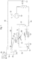
- the Fig. 1 shows a device for cooling milk with a milk cooling tank 1, the terms milk cooling tank, milk tank and tank being used as synonyms in the present application.
- the milk cooling tank 1 has a milk inlet 2 in its upper part and a milk outlet 3 in the lower part of the tank 1. It also has a part of a cooling device comprising a cooling circuit 5.
- the cooling circuit 5 has, in a manner known per se, a compressor 6, a condenser 9, a thermostatic expansion valve 11 and an evaporator 4.
- the compressor 6 is driven by the motor 7.
- the cooling circuit contains a refrigerant. circulating, which changes state of aggregation inside the cooling circuit.
- the evaporator 4 takes heat of evaporation from the environment, which causes the environment to cool. This phenomenon takes place in the evaporator 4.
- This is arranged on the underside of the milk cooling tank, preferably along a part of the cylindrical casing surface thereof, so that the milk cools by transferring heat to the evaporator.
- a temperature sensor 13 is arranged, in particular in the lower part of the tank 1, to monitor the temperature of the milk and to regulate the various components of the cooling circuit 5 accordingly.
- a milk volume sensor e.g. a filling level sensor and / or a level switch may be provided to allow fine adjustment of the cooling as a function of the volume of milk.
- the condenser 9 of the cooling circuit 5 is placed outside the milk cooling tank 1, but it forms part of the device for cooling milk, like the rest of the cooling circuit. It is used to change the fluid from the gaseous state to the liquid state. Condensation heat is then produced and evacuated into the environment. For this, the condenser 9 has a fan 17 which regulates the heat removal.
- the temperature sensor 13 determines the temperature of the milk in the milk cooling tank 1 and transmits it via a signal line to a control terminal 23 near the tank 1.
- the control terminal 23 is placed within sight of the tank 1 and preferably less than 10 meters, in particular less than one meter from tank 1, or preferably, and in particular, connected to tank 1.
- the control terminal 23 has a control and / or analysis unit 16 which is designed to receive a sensor signal transmitted over the signal line 14. This can be converted by a signal converter 15 into a signal line. format adapted to the control and / or analysis unit.
- the measurement converter 15 of this variant of execution is associated with the control terminal 23. It can however also, as an option, be arranged at the level of the temperature probe 13, or the temperature probe 13 as well as the terminal. control 23 can each have a measurement converter 15.
- control terminal 23 has an output unit, for example a screen, on which the process parameters can be displayed, among other things, and the setting of the operating modes of the milk cooling tank 1 can be carried out. .
- the control and / or analysis unit 16 provides, depending on a transmitted signal sensor, e.g. by the temperature sensor 13, a control and / or a regulation of the various components of the cooling circuit. This concerns, among other things, the control and / or regulation of the motor 7 of the compressor, and optionally the control of the fan 17 and / or of the expansion valve 11.
- the control terminal has a signal line 18. and 19 for each.
- the tank 1 further has a stirrer 8 with a motor 10 for stirring the cooled milk, so that the milk is uniformly guided on the cooling surface of the tank 1 and prevented from freezing and at the same time is homogenized.
- the operation of the stirrer 8, in particular the stirring speed, is also adjustable by controlling and / or regulating the motor 10 by the control terminal 23, in particular by the control unit and / or d Analysis 16.
- the stirrer has a signal line 12 for connection to the control terminal 23.
- the reservoir 1 also has a cleaning device 20.
- the cleaning device has, in the Fig. 1 , a nozzle at its end and a bar-shaped arrival.
- a metering pump and a reservoir for one or more cleaning products can be placed outside the reservoir 1.
- the cleaning can be carried out, for example, as a CIP cleaning in place or according to other usual standards in the field. food.
- the start time, duration and dosage of the cleaning product (s) by the cleaning device 20 can be set, in other words controlled and / or regulated, by a corresponding signal transmitted on the signal line 21 by the control terminal 23, in particular by the control and / or analysis unit.
- the cleaning device may have corresponding sensors, e.g. flowmeters or temperature sensors, with which the dosing quantity during cleaning or other measured variables, for example the temperature of the cleaning agent, can be determined. These sensor signals can be transmitted via the signal line 21 to the control and / or analysis unit 16.
- sensors e.g. flowmeters or temperature sensors, with which the dosing quantity during cleaning or other measured variables, for example the temperature of the cleaning agent, can be determined.
- These sensor signals can be transmitted via the signal line 21 to the control and / or analysis unit 16.
- the signal converter 15 can also convert the sensor signals of the other aforementioned sensors or control signals for the control of different components of the milk cooling tank.
- the signal lines of the present invention can be realized as cable lines, but a design like wireless signal lines is also possible.
- the control terminal 23 has a transmitter module 31, preferably a radio module, for transmitting signals to an external computer 24, for example a mobile device such as a mobile phone or a tablet.
- the external computer can also be a control panel of a higher level control system.
- the signal transmission comprises a first signal transmission path 25 from the control terminal 23 to the external computer 24 and a second signal transmission path 26 from the external computer 24 to the control terminal, this second signal transmission path.
- signals 26 for controlling and / or regulating certain devices of the milk cooling tank, in particular for controlling and / or regulating the cleaning device 20, and possibly for controlling and / or regulating the device cooling, in particular of the motor 7 and of the fan 17 of the cooling device, of the agitator 8 and / or of the control terminal 23 itself.
- the control terminal 23 can, for example, represent a cause of injury due to the heat of the internal resistances during a self-test or maintenance work.
- a main application is the control of the cleaning device 20.
- the control and regulation of this cleaning device can be performed by the external computer 24.
- the problem with controlling the various devices by an external computer 24 is that the milk cooling tank 1 is an accessible tank.
- the milk cooling tank 1 has, in the usual construction, a manhole 27. An operator can go through this. manhole 27 to get inside the tank 1 and, for example, inspect the tank for residual impurities or repair some components inside the tank 1.
- cleaner 20 While agitator 8 generally rotates relatively slowly, cleaner 20 represents an increased danger. He most often uses aggressive cleaning products.
- the fan 17 of the condenser 9 or the resistors inside the control terminal 23 represent other causes of injury. These two components are inactive when the milk cooling tank 1 is emptied and ready to fill. A control and / or regulation by the external computer can, here also, accidentally lead to injury to an operator who performs work on the device.
- control terminal 23 has a control element 29 which establishes a time-limited contact to activate the second signal transmission path 26 for access by the external computer 24.
- This time-limited contact allows the operator of the external computer 24 to control certain devices and / or programs which are otherwise disabled, for example grayed out, in the menu of the external computer.
- the second signal transmission path 26 for control and / or regulation therefore relates in particular to the cleaning device, but can be extended to other controls and / or regulations such as the components of the cooling circuit 5 or the terminal. control 23.
- the operator can activate the access of the external computer with the aid of the control element 29 and thus the second signal transmission channel 26.
- Adjustment tests of the cleaning device 20 can then be carried out at a fixed time interval, e.g. by the external computer 24.
- the second signaling channel is deactivated automatically, and with it the access of the external computer 24.
- actuating element 29 has been activated or not, to ensure signal transmission, e.g. by the first signaling channel 25, from the milk cooling tank or from the control terminal 23 to the external computer 24 or to other external computers.
- This signal transmission from the milk cooling tank to the external computer is thus constantly maintained, except in the event of a technical fault.
- Signal transmission guarantees the transmission of process data to one or more operators, e.g. the stirring speed, the milk temperature, the parameters for adjusting the milk temperature, the volume of milk in tank 1, etc.
- the time interval described should preferably be less than 40 minutes, in particular between 10 and 30 minutes.
- the actuating element can then only be actuated on the control terminal 23 in order to prevent an extension of the authorization by the operator on the external computer 24.
- Access to the control of certain components, in other words of the agitator 8, of the cleaning device 20 and of the cooling circuit 5 of the device for cooling milk can also be carried out directly using the control terminal 23
- the operator of the control terminal 23 and that of the external computer 24 preferably have the same priority, during said time interval, to control the components of the device for cooling milk.
- the external computer can execute, when the actuating element 29 is activated, various menus whose external access is otherwise deactivated.
- the actuator 29 may preferably be an actuator button which can be shaped as a digital actuator or as a physical actuator.
- the person who uses the actuating element 29 is primarily responsible for the absence of an accident of an operator on or in the milk cooling tank. It can also make adjustments to the milk cooling tank 1 and the various components using the control terminal 23, but this task can also be transferred to the operator of the external computer 24. This operator does not have however while of a limited time interval.
- a further actuating element can be provided which removes its access to the external computer.
- Activation of a sensor when actuating the manhole cover 27 may also result in the deactivation of the access of the external computer, which adds further safety level at the device for cooling milk.
- Signals transmitted to the computer can be process parameters and / or process information. They include, among other things, the modification of process parameters, for example the temperature of the milk or the arrival of milk. An alarm can also be transmitted to the external computer 24, for example when the temperature of the milk is exceeded, and emitted by the latter.
- a history for example faults, or measurement curves can also be transmitted to the external computer 24.
- the cleaning of the tank 1 by the cleaning device 20 can take about 30 minutes to 1 hour and can be carried out, for example, every two or three days.
- a downtime can be left between cleaning and a new commissioning of the tank, for example by activating the cooling.
- the operating state of the tank eg. emptying, empty state, cleaning, milk collection, etc. can be represented by different colors in a display board of the external computer 24 and / or of the control terminal 23.
- the Fig. 2 shows another view of the signal data transmission from the control terminal 23 of the milk cooling tank 1 to the external computer 24.
- the milk cooling tank 1 has a manhole 27 and may include all the other components of the device for cooling milk shown in figure. Fig. 1 .
- the signal converter 15 and the transmitter module 31 are also shown, for clarity, outside the housing of the control terminal 23. In reality, however, these components may preferably be integrated into the housing of the control terminal. control.
- the signal converter 15 is highlighted separately. It can be a master element, eg. a lO-Link link master of a communication system, preferably a lO-Link link system, which can be used to connect intelligent sensors and actuators 51 to 54. Data transmission between the system communication and the other components of the control terminal 23 can take the form of a bus communication protocol, preferably via Modbus.
- the sensors can be, for example, temperature probes for monitoring the temperature of milk or the temperature of the cleaning agent or a flow rate sensor for monitoring the incoming volume of milk and / or cleaning liquid and the like.
- the actuators can achieve, for example, a power take-off on the motor of the agitator.
- the exchange of data between the transmitter module 31 and the other components of the control terminal 23, in particular the control and / or analysis unit not shown in the Fig. 2 , can be done via an Ethernet connection.
- the transmitter module 31 can be configured as a router, in particular a VPN router. It can preferably establish a communication with an IT infrastructure 40 in the Internet, also called a cloud or cloud.
- Signal transmission can be through a wireless signal line 25 or over a wired signal line 25 '.
- the transmission to the IT infrastructure allows the signals and thus the information to be called simultaneously by several external computers 24 and 30 which are symbolized, in the Fig. 2 , by a mobile phone 30 and a laptop 24.
- a single external computer here the computer 24, can access the various components of the milk cooling tank 1, in particular the cleaning device, but optionally also the agitator and the cooling circuit.
- a signal line 26 which can be a wireless or wired line.
- the access of the external computer is limited in time and the element actuation can only be actuated by a person at the control terminal 23, who has preferably first checked the milk cooling tank and the other components of the milk cooling device.
- the critical moments are when the tank is empty, when the tank is empty, when the empty tank is put back into service, the cleaning is activated and the cleaning is carried out, which usually takes place in several cycles.
- the actuator 29 may preferably be deactivated or no access is granted to the external computer.
- the emptying is preferably always priority on the other accesses.
- the commissioning of a drained tank 1, in particular, can be carried out by accessing the external computer 24.
- the Fig. 3 shows a first view of a first control window 100 on the screen of the control terminal 23. This may be an availability display.
- Symbol 101 represents the actuating element for authorizing access from an external computer.
- This external computer has a program which authorizes its access to the device for cooling milk according to the present invention.
- the program allows, for example, to select the milk cooling tank to be accessed.
- a person on site is notified by the operator of the external computer, for example by SMS or by a call, he inspects the affected milk cooling tank and the rest of the device for the cooling of milk and then activates the actuating element 101 on the screen of the control terminal.
- a query window 102 with an input field 103 in which an access code is requested, is displayed in the command window 100.
- This code prevents the authorization of external access to be granted to a person who is not. authorized. It can be confirmed after the entry by a control panel 104 and 105 or the entry can be abandoned.
- a display window 106 with warnings then appears in the control panel.
- Symbol 109 represents a person passing through the manhole of a milk cooling tank. It is intended to remind the person at the control terminal once again of their responsibility to check the milk cooling tank.
- the entry in a control panel 107 and 108 confirms the check, or the entry can be abandoned.
- the operator of the external computer now has access to the device for cooling milk according to the present invention.
- the control panel 100 then displays a time indication 110 for the remaining access time. This time indication can also be communicated to the external computer.
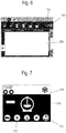
- the Fig. 7 shows a view of a second command window 113 on the external computer.
- the operator has a choice of different menu items.
- control panels 112 and 111 are of particular interest in that they relate to the cooling program and the cleaning program. Activation of these control panels opens submenus and allows parameters to be adjusted and cooling or cleaning to be started.
- the current temperature of the milk is transmitted to the control panel 114.
- the control panels 111 and 112 are deactivated and, for example, grayed out.
- the current temperature display remains.
Landscapes
- Life Sciences & Earth Sciences (AREA)
- Animal Husbandry (AREA)
- Environmental Sciences (AREA)
- Devices That Are Associated With Refrigeration Equipment (AREA)
Claims (15)
- Vorrichtung zur Milchkühlung umfassend wenigstens einen begehbaren Milchkühltank (1), der durch ein Mannloch zugänglich ist, das durch einen Deckel verschlossen ist, und wenigstens einen Kühlkreislauf (5) zum Abkühlen der Milch innerhalb des Milchkühltank (1), wobei der Milchkühltank (1) eine Reinigungsvorrichtung (20) aufweist und wobei die Vorrichtung zum Kühlen der Milch ein Kontrollterminal (23) in Sichtweite des Milchkühltanks (1) aufweist,
dadurch gekennzeichnet, dass
das Kontrollterminal (23) ein Betätigungselement (29) aufweist, bei dessen Betätigung eine Freigabe zum Zugriff auf die Reinigungsvorrichtung (20) durch einen externen Rechner (24) erfolgt, wobei die Freigabe innerhalb eines Zeitintervalls zeitlich begrenzt ist; und
wobei das Kontrollterminal (23) ausgerüstet ist, zum Senden von Daten, insbesondere betreffend die Prozessbedingungen im Milchkühltank (1), unabhängig vom Zustand des Betätigungselements (29). - Vorrichtung zur Milchkühlung nach Anspruch 1, dadurch gekennzeichnet, dass der Zugriff zeitlich limitiert ist.
- Vorrichtung zur Milchkühlung nach Anspruch 1 oder 2, dadurch gekennzeichnet, dass die Betätigung des Betätigungselements (29) eine Freigabe des Zugriffs auf Bauteile des Kühlkreislaufs (5) durch einen externen Rechner (24) erfolgt.
- Vorrichtung zur Milchkühlung nach Anspruch 1 oder 2, dadurch gekennzeichnet, dass die Vorrichtung ein Rührwerk (8) aufweist, wobei durch die Betätigung des Betätigungselements (29) eine Freigabe zum Zugriff auf das Rührwerk (8) durch einen externen Rechner (24) erfolgt.
- Vorrichtung zur Milchkühlung nach einem der vorhergehenden Ansprüche, dadurch gekennzeichnet, dass das Kontrollterminal (23) eine Anzeige der verbleibenden Zeit des Zugriffs durch den externen Rechner (24) aufweist.
- Verfahren zum Verwalten einer Vorrichtung zur Milchkühlung, umfassend wenigstens einen begehbaren Milchkühltank (1), der durch ein Mannloch zugänglich ist, das durch einen Deckel verschlossen ist, und wenigstens einen Kühlkreislauf (5) zum Abkühlen von Milch in dem Milchkühltank (1),
wobei der Milchkühltank (1) eine Reinigungsvorrichtung (20) umfasst, mit der ein Reinigungsmodus ausführbar ist, und wobei die Vorrichtung zur Milchkühlung ein Kontrollterminal (23) in Sichtweite des Milchkühltanks (1) aufweist,
dadurch gekennzeichnet, dass das Kontrollterminal (23) ein Betätigungselement (29) aufweist, dessen Betätigung eine Freigabe zur Einstellung des Reinigungsmodus durch einen externen Rechner (24) erfolgt; und
wobei die Vorrichtung zur Milchkühlung eine Datenübertragung von Daten an den einen externen Rechner oder an weitere externen Rechner (24) unabhängig vom Zustand des Betätigungselements (29) durchführt, und dass die Freigabe innerhalb eines Zeitintervalls zeitlich begrenzt ist. - Verfahren nach Anspruch 6, dadurch gekennzeichnet, dass das Zeitintervall maximal 40 Minuten, insbesondere 10 bis 30 Minuten, dauert.
- Verfahren nach Anspruch 6 oder 7, dadurch gekennzeichnet, dass die Betätigung des Betätigungselements (29) eine Freigabe der Einstellung eines Kühlmodus durch einen externen Computer (24) erfolgt.
- Verfahren nach einem der Ansprüche 6 bis 8, dadurch gekennzeichnet, dass durch die Betätigung des Betätigungselements (29) eine Freigabe zur Inbetriebnahme oder eine Änderung des Betriebsmodus des Milchkühltanks (1) und des Kontrollterminals (23) durch einen externen Computer (24) und somit eine Temperaturänderung von Widerständen in dem Steuerterminal (23) erfolgt.
- Verfahren nach einem der Ansprüche 6 bis 9, dadurch gekennzeichnet, dass durch die Betätigung des Betätigungselements (29) eine Freigabe eines Testmodus zum Einzelzugriff auf verschiedene Bauteile der Vorrichtung zur Milchkühlung, insbesondere von Bauteilen des Rührwerks (8), der Reinigungsvorrichtung (20) und/oder des Kühlkreislaufs (5), erfolgt.
- Verfahren nach einem der Ansprüche 6 bis 10, dadurch gekennzeichnet, dass der Zugriff des externen Rechners (24) auf die Vorrichtung zur Milchkühlung durch eine Drahtlosverbindung und/oder durch ein drahtgebundenes Netzwerk erfolgt.
- Verfahren nach einem der Ansprüche 6 bis 11, dadurch gekennzeichnet, dass die Datenübertragung durch die Vorrichtung zur Milchkühlung an eine IT-infrastruktur, insbesondere eine Cloud (40), erfolgt, sodass die übertragenen Daten von mehreren Rechnern zeitgleich, insbesondere über eine Drahtlosverbindung, abrufbar sind.
- Verfahren nach einem der Ansprüche 6 bis 12, dadurch gekennzeichnet, dass die übertragenen Daten zumindest eine oder mehrere der folgenden Daten umfassen:die Milchtemperatur;die Milchmenge;die Rührgeschwindigkeit;die Reinigungsbedingungen im Reinigungsmodus, vorzugsweise die Temperatur eines oder mehrerer Reinigungsmedien und/oder die Dosierung des oder der Reinigungsmedien;eines oder mehrere Verlaufsdiagramme, vorzugsweise betreffend die Milchtemperatur, die Milchmenge und/oder des Reinigungsmodus;die Historie vorzugsweise von Prozessänderungen, vorzugsweise von Änderungen des Betriebsmodus, von Fehlermeldungen und/oder von Änderungen von Grenzwerten;die Anzeige bestehender Grenzwerte;Warnmeldungen; und/oderdie Anzeige des aktuellen Betriebsmodus, insbesondere des Kühlmodus, des Stillstands, des Entleerungsmodus oder des Reinigungsmodus.
- Verfahren nach einem der Ansprüche 6 bis 13, dadurch gekennzeichnet, dass durch die Betätigung des Betätigungselements (29) eine Freigabe der Einstellung von Grenzwerten oder eine Einstellung von Betriebsmodi erfolgt.
- Verfahren nach einem der Ansprüche 6 bis 14, dadurch gekennzeichnet, dass der begehbare Milchkühltank durch ein Mannloch (27) begehbar ist, das durch einen Deckel verschlossen ist, wobei das Mannloch (27) einen Sensor aufweist, der den Öffnungszustand des Deckels anzeigt und wobei bei Änderung des Öffnungszustandes des Deckels eine Deaktivierung des Zugriff des externen Rechners (24) erfolgt.
Priority Applications (1)
| Application Number | Priority Date | Filing Date | Title |
|---|---|---|---|
| EP18205447.8A EP3649850B1 (de) | 2018-11-09 | 2018-11-09 | Vorrichtung für die kühlung von milch, und steuerverfahren einer vorrichtung für die kühlung von milch |
Applications Claiming Priority (1)
| Application Number | Priority Date | Filing Date | Title |
|---|---|---|---|
| EP18205447.8A EP3649850B1 (de) | 2018-11-09 | 2018-11-09 | Vorrichtung für die kühlung von milch, und steuerverfahren einer vorrichtung für die kühlung von milch |
Publications (2)
| Publication Number | Publication Date |
|---|---|
| EP3649850A1 EP3649850A1 (de) | 2020-05-13 |
| EP3649850B1 true EP3649850B1 (de) | 2021-08-25 |
Family
ID=64270723
Family Applications (1)
| Application Number | Title | Priority Date | Filing Date |
|---|---|---|---|
| EP18205447.8A Active EP3649850B1 (de) | 2018-11-09 | 2018-11-09 | Vorrichtung für die kühlung von milch, und steuerverfahren einer vorrichtung für die kühlung von milch |
Country Status (1)
| Country | Link |
|---|---|
| EP (1) | EP3649850B1 (de) |
Families Citing this family (1)
| Publication number | Priority date | Publication date | Assignee | Title |
|---|---|---|---|---|
| FR3111689B1 (fr) * | 2020-06-18 | 2022-09-09 | Serap Industries | procédé de refroidissement d’un liquide, programme et mémoire d’ordinateur pour sa mise en œuvre |
Family Cites Families (3)
| Publication number | Priority date | Publication date | Assignee | Title |
|---|---|---|---|---|
| NZ272754A (en) * | 1995-08-10 | 1997-03-24 | Michael Joseph Uttinger | Data aquisition; remote system for logging temperature of bulk milk; details |
| NL1021430C1 (nl) * | 2002-08-06 | 2004-02-10 | Lely Entpr Ag | Inrichting voor het bewaken van een melktank, samenstel van een melkrobot met automatische opstartinrichting en een dergelijke inrichting. |
| US7886959B2 (en) * | 2007-03-19 | 2011-02-15 | Western Kentucky University | Security monitoring system for a bulk foodstuff transport container |
-
2018
- 2018-11-09 EP EP18205447.8A patent/EP3649850B1/de active Active
Also Published As
| Publication number | Publication date |
|---|---|
| EP3649850A1 (de) | 2020-05-13 |
Similar Documents
| Publication | Publication Date | Title |
|---|---|---|
| US10541902B1 (en) | Network device management technology | |
| US8781633B2 (en) | Monitoring and control systems and methods | |
| JP2002366223A (ja) | 装置動作パラメータの遠隔管理システムおよび方法 | |
| WO2014134718A1 (en) | System, method and computer readable medium for managing mobile devices | |
| FR2852623A1 (fr) | Dispositif et procede d'actionnement d'une barriere mobile, notamment d'une porte anti-incendie | |
| EP3649850B1 (de) | Vorrichtung für die kühlung von milch, und steuerverfahren einer vorrichtung für die kühlung von milch | |
| EP2032856B1 (de) | Konfigurationstechniken für pumpstation | |
| CA2697952A1 (en) | An electronic point of sales vending control apparatus | |
| US20250388453A1 (en) | Anomaly detection during fuel dispensing operations using fuel volume determinations | |
| GB2311767A (en) | Dosing control apparatus | |
| WO2015101755A2 (fr) | Systeme et procece d'aide au diagnostic de l'etat de fonctionnement d'une machine tournante | |
| EP3816854A1 (de) | Verfahren und vorrichtung zur verbesserten kontrolle von schwimmbädern | |
| US6788209B2 (en) | Automatic emergency shut-off system for delivery transports | |
| AU2011100176A4 (en) | Door Operator and Method | |
| US11477546B2 (en) | User configurable remote environmental monitoring system | |
| JP2025524850A (ja) | ガソリンスタンドのネットワーク内の異常な燃料供給動作に関連付けられた位置の検出 | |
| US11993507B2 (en) | Anomaly detection and controlling fuel dispensing operations using fuel volume determinations | |
| EP0991987A1 (de) | Vorrichtung zur regelung einer anlage | |
| EP0586319B1 (de) | System zum Fernüberwachen von geschützten Räumen | |
| EP0562992A1 (de) | Zugangskontrollsystem für geschützte Räume | |
| US20200411202A1 (en) | Method and system for enabling cloud communications with appliances | |
| WO2025024347A1 (en) | Anomaly detection and controlling fuel dispensing operations using fuel volume determinations | |
| EP1388830B1 (de) | Verfahren und System zur Fernsteuerung von Geräten | |
| CN119084307A (zh) | 一种具有访问权限控制功能的租赁真空泵 | |
| AU2011201387B2 (en) | Door Operator and Method |
Legal Events
| Date | Code | Title | Description |
|---|---|---|---|
| PUAI | Public reference made under article 153(3) epc to a published international application that has entered the european phase |
Free format text: ORIGINAL CODE: 0009012 |
|
| STAA | Information on the status of an ep patent application or granted ep patent |
Free format text: STATUS: THE APPLICATION HAS BEEN PUBLISHED |
|
| AK | Designated contracting states |
Kind code of ref document: A1 Designated state(s): AL AT BE BG CH CY CZ DE DK EE ES FI FR GB GR HR HU IE IS IT LI LT LU LV MC MK MT NL NO PL PT RO RS SE SI SK SM TR |
|
| AX | Request for extension of the european patent |
Extension state: BA ME |
|
| STAA | Information on the status of an ep patent application or granted ep patent |
Free format text: STATUS: REQUEST FOR EXAMINATION WAS MADE |
|
| 17P | Request for examination filed |
Effective date: 20201109 |
|
| RBV | Designated contracting states (corrected) |
Designated state(s): AL AT BE BG CH CY CZ DE DK EE ES FI FR GB GR HR HU IE IS IT LI LT LU LV MC MK MT NL NO PL PT RO RS SE SI SK SM TR |
|
| RAP1 | Party data changed (applicant data changed or rights of an application transferred) |
Owner name: GEA FARM TECHNOLOGIES JAPY SAS |
|
| GRAP | Despatch of communication of intention to grant a patent |
Free format text: ORIGINAL CODE: EPIDOSNIGR1 |
|
| STAA | Information on the status of an ep patent application or granted ep patent |
Free format text: STATUS: GRANT OF PATENT IS INTENDED |
|
| INTG | Intention to grant announced |
Effective date: 20210324 |
|
| GRAS | Grant fee paid |
Free format text: ORIGINAL CODE: EPIDOSNIGR3 |
|
| GRAA | (expected) grant |
Free format text: ORIGINAL CODE: 0009210 |
|
| STAA | Information on the status of an ep patent application or granted ep patent |
Free format text: STATUS: THE PATENT HAS BEEN GRANTED |
|
| AK | Designated contracting states |
Kind code of ref document: B1 Designated state(s): AL AT BE BG CH CY CZ DE DK EE ES FI FR GB GR HR HU IE IS IT LI LT LU LV MC MK MT NL NO PL PT RO RS SE SI SK SM TR |
|
| REG | Reference to a national code |
Ref country code: CH Ref legal event code: EP |
|
| REG | Reference to a national code |
Ref country code: IE Ref legal event code: FG4D Free format text: LANGUAGE OF EP DOCUMENT: FRENCH Ref country code: AT Ref legal event code: REF Ref document number: 1422844 Country of ref document: AT Kind code of ref document: T Effective date: 20210915 |
|
| REG | Reference to a national code |
Ref country code: DE Ref legal event code: R096 Ref document number: 602018022317 Country of ref document: DE |
|
| REG | Reference to a national code |
Ref country code: LT Ref legal event code: MG9D |
|
| REG | Reference to a national code |
Ref country code: NL Ref legal event code: MP Effective date: 20210825 |
|
| REG | Reference to a national code |
Ref country code: AT Ref legal event code: MK05 Ref document number: 1422844 Country of ref document: AT Kind code of ref document: T Effective date: 20210825 |
|
| PG25 | Lapsed in a contracting state [announced via postgrant information from national office to epo] |
Ref country code: HR Free format text: LAPSE BECAUSE OF FAILURE TO SUBMIT A TRANSLATION OF THE DESCRIPTION OR TO PAY THE FEE WITHIN THE PRESCRIBED TIME-LIMIT Effective date: 20210825 Ref country code: ES Free format text: LAPSE BECAUSE OF FAILURE TO SUBMIT A TRANSLATION OF THE DESCRIPTION OR TO PAY THE FEE WITHIN THE PRESCRIBED TIME-LIMIT Effective date: 20210825 Ref country code: FI Free format text: LAPSE BECAUSE OF FAILURE TO SUBMIT A TRANSLATION OF THE DESCRIPTION OR TO PAY THE FEE WITHIN THE PRESCRIBED TIME-LIMIT Effective date: 20210825 Ref country code: SE Free format text: LAPSE BECAUSE OF FAILURE TO SUBMIT A TRANSLATION OF THE DESCRIPTION OR TO PAY THE FEE WITHIN THE PRESCRIBED TIME-LIMIT Effective date: 20210825 Ref country code: RS Free format text: LAPSE BECAUSE OF FAILURE TO SUBMIT A TRANSLATION OF THE DESCRIPTION OR TO PAY THE FEE WITHIN THE PRESCRIBED TIME-LIMIT Effective date: 20210825 Ref country code: LT Free format text: LAPSE BECAUSE OF FAILURE TO SUBMIT A TRANSLATION OF THE DESCRIPTION OR TO PAY THE FEE WITHIN THE PRESCRIBED TIME-LIMIT Effective date: 20210825 Ref country code: AT Free format text: LAPSE BECAUSE OF FAILURE TO SUBMIT A TRANSLATION OF THE DESCRIPTION OR TO PAY THE FEE WITHIN THE PRESCRIBED TIME-LIMIT Effective date: 20210825 Ref country code: BG Free format text: LAPSE BECAUSE OF FAILURE TO SUBMIT A TRANSLATION OF THE DESCRIPTION OR TO PAY THE FEE WITHIN THE PRESCRIBED TIME-LIMIT Effective date: 20211125 Ref country code: PT Free format text: LAPSE BECAUSE OF FAILURE TO SUBMIT A TRANSLATION OF THE DESCRIPTION OR TO PAY THE FEE WITHIN THE PRESCRIBED TIME-LIMIT Effective date: 20211227 Ref country code: NO Free format text: LAPSE BECAUSE OF FAILURE TO SUBMIT A TRANSLATION OF THE DESCRIPTION OR TO PAY THE FEE WITHIN THE PRESCRIBED TIME-LIMIT Effective date: 20211125 |
|
| PG25 | Lapsed in a contracting state [announced via postgrant information from national office to epo] |
Ref country code: PL Free format text: LAPSE BECAUSE OF FAILURE TO SUBMIT A TRANSLATION OF THE DESCRIPTION OR TO PAY THE FEE WITHIN THE PRESCRIBED TIME-LIMIT Effective date: 20210825 Ref country code: LV Free format text: LAPSE BECAUSE OF FAILURE TO SUBMIT A TRANSLATION OF THE DESCRIPTION OR TO PAY THE FEE WITHIN THE PRESCRIBED TIME-LIMIT Effective date: 20210825 Ref country code: GR Free format text: LAPSE BECAUSE OF FAILURE TO SUBMIT A TRANSLATION OF THE DESCRIPTION OR TO PAY THE FEE WITHIN THE PRESCRIBED TIME-LIMIT Effective date: 20211126 |
|
| PG25 | Lapsed in a contracting state [announced via postgrant information from national office to epo] |
Ref country code: NL Free format text: LAPSE BECAUSE OF FAILURE TO SUBMIT A TRANSLATION OF THE DESCRIPTION OR TO PAY THE FEE WITHIN THE PRESCRIBED TIME-LIMIT Effective date: 20210825 |
|
| PG25 | Lapsed in a contracting state [announced via postgrant information from national office to epo] |
Ref country code: DK Free format text: LAPSE BECAUSE OF FAILURE TO SUBMIT A TRANSLATION OF THE DESCRIPTION OR TO PAY THE FEE WITHIN THE PRESCRIBED TIME-LIMIT Effective date: 20210825 |
|
| REG | Reference to a national code |
Ref country code: DE Ref legal event code: R097 Ref document number: 602018022317 Country of ref document: DE |
|
| PG25 | Lapsed in a contracting state [announced via postgrant information from national office to epo] |
Ref country code: SM Free format text: LAPSE BECAUSE OF FAILURE TO SUBMIT A TRANSLATION OF THE DESCRIPTION OR TO PAY THE FEE WITHIN THE PRESCRIBED TIME-LIMIT Effective date: 20210825 Ref country code: SK Free format text: LAPSE BECAUSE OF FAILURE TO SUBMIT A TRANSLATION OF THE DESCRIPTION OR TO PAY THE FEE WITHIN THE PRESCRIBED TIME-LIMIT Effective date: 20210825 Ref country code: RO Free format text: LAPSE BECAUSE OF FAILURE TO SUBMIT A TRANSLATION OF THE DESCRIPTION OR TO PAY THE FEE WITHIN THE PRESCRIBED TIME-LIMIT Effective date: 20210825 Ref country code: EE Free format text: LAPSE BECAUSE OF FAILURE TO SUBMIT A TRANSLATION OF THE DESCRIPTION OR TO PAY THE FEE WITHIN THE PRESCRIBED TIME-LIMIT Effective date: 20210825 Ref country code: CZ Free format text: LAPSE BECAUSE OF FAILURE TO SUBMIT A TRANSLATION OF THE DESCRIPTION OR TO PAY THE FEE WITHIN THE PRESCRIBED TIME-LIMIT Effective date: 20210825 Ref country code: AL Free format text: LAPSE BECAUSE OF FAILURE TO SUBMIT A TRANSLATION OF THE DESCRIPTION OR TO PAY THE FEE WITHIN THE PRESCRIBED TIME-LIMIT Effective date: 20210825 |
|
| PG25 | Lapsed in a contracting state [announced via postgrant information from national office to epo] |
Ref country code: MC Free format text: LAPSE BECAUSE OF FAILURE TO SUBMIT A TRANSLATION OF THE DESCRIPTION OR TO PAY THE FEE WITHIN THE PRESCRIBED TIME-LIMIT Effective date: 20210825 |
|
| REG | Reference to a national code |
Ref country code: CH Ref legal event code: PL |
|
| PLBE | No opposition filed within time limit |
Free format text: ORIGINAL CODE: 0009261 |
|
| STAA | Information on the status of an ep patent application or granted ep patent |
Free format text: STATUS: NO OPPOSITION FILED WITHIN TIME LIMIT |
|
| PG25 | Lapsed in a contracting state [announced via postgrant information from national office to epo] |
Ref country code: LU Free format text: LAPSE BECAUSE OF NON-PAYMENT OF DUE FEES Effective date: 20211109 Ref country code: IT Free format text: LAPSE BECAUSE OF FAILURE TO SUBMIT A TRANSLATION OF THE DESCRIPTION OR TO PAY THE FEE WITHIN THE PRESCRIBED TIME-LIMIT Effective date: 20210825 Ref country code: BE Free format text: LAPSE BECAUSE OF NON-PAYMENT OF DUE FEES Effective date: 20211130 |
|
| REG | Reference to a national code |
Ref country code: BE Ref legal event code: MM Effective date: 20211130 |
|
| 26N | No opposition filed |
Effective date: 20220527 |
|
| PG25 | Lapsed in a contracting state [announced via postgrant information from national office to epo] |
Ref country code: SI Free format text: LAPSE BECAUSE OF FAILURE TO SUBMIT A TRANSLATION OF THE DESCRIPTION OR TO PAY THE FEE WITHIN THE PRESCRIBED TIME-LIMIT Effective date: 20210825 |
|
| PG25 | Lapsed in a contracting state [announced via postgrant information from national office to epo] |
Ref country code: FR Free format text: LAPSE BECAUSE OF NON-PAYMENT OF DUE FEES Effective date: 20211130 |
|
| PG25 | Lapsed in a contracting state [announced via postgrant information from national office to epo] |
Ref country code: CY Free format text: LAPSE BECAUSE OF FAILURE TO SUBMIT A TRANSLATION OF THE DESCRIPTION OR TO PAY THE FEE WITHIN THE PRESCRIBED TIME-LIMIT Effective date: 20210825 |
|
| GBPC | Gb: european patent ceased through non-payment of renewal fee |
Effective date: 20221109 |
|
| PG25 | Lapsed in a contracting state [announced via postgrant information from national office to epo] |
Ref country code: LI Free format text: LAPSE BECAUSE OF NON-PAYMENT OF DUE FEES Effective date: 20220630 Ref country code: HU Free format text: LAPSE BECAUSE OF FAILURE TO SUBMIT A TRANSLATION OF THE DESCRIPTION OR TO PAY THE FEE WITHIN THE PRESCRIBED TIME-LIMIT; INVALID AB INITIO Effective date: 20181109 Ref country code: CH Free format text: LAPSE BECAUSE OF NON-PAYMENT OF DUE FEES Effective date: 20220630 |
|
| PG25 | Lapsed in a contracting state [announced via postgrant information from national office to epo] |
Ref country code: GB Free format text: LAPSE BECAUSE OF NON-PAYMENT OF DUE FEES Effective date: 20221109 |
|
| PG25 | Lapsed in a contracting state [announced via postgrant information from national office to epo] |
Ref country code: MK Free format text: LAPSE BECAUSE OF FAILURE TO SUBMIT A TRANSLATION OF THE DESCRIPTION OR TO PAY THE FEE WITHIN THE PRESCRIBED TIME-LIMIT Effective date: 20210825 |
|
| PG25 | Lapsed in a contracting state [announced via postgrant information from national office to epo] |
Ref country code: MT Free format text: LAPSE BECAUSE OF FAILURE TO SUBMIT A TRANSLATION OF THE DESCRIPTION OR TO PAY THE FEE WITHIN THE PRESCRIBED TIME-LIMIT Effective date: 20210825 |
|
| PG25 | Lapsed in a contracting state [announced via postgrant information from national office to epo] |
Ref country code: TR Free format text: LAPSE BECAUSE OF FAILURE TO SUBMIT A TRANSLATION OF THE DESCRIPTION OR TO PAY THE FEE WITHIN THE PRESCRIBED TIME-LIMIT Effective date: 20210825 |
|
| PGFP | Annual fee paid to national office [announced via postgrant information from national office to epo] |
Ref country code: DE Payment date: 20251021 Year of fee payment: 8 |
|
| PGFP | Annual fee paid to national office [announced via postgrant information from national office to epo] |
Ref country code: IE Payment date: 20251008 Year of fee payment: 8 |