EP3649827B1 - Agrégation d'interfaces radio multiples prenant en charge des réseaux 4g/5g multifournisseurs - Google Patents
Agrégation d'interfaces radio multiples prenant en charge des réseaux 4g/5g multifournisseurs Download PDFInfo
- Publication number
- EP3649827B1 EP3649827B1 EP17780533.0A EP17780533A EP3649827B1 EP 3649827 B1 EP3649827 B1 EP 3649827B1 EP 17780533 A EP17780533 A EP 17780533A EP 3649827 B1 EP3649827 B1 EP 3649827B1
- Authority
- EP
- European Patent Office
- Prior art keywords
- bearer
- user equipment
- network element
- internet protocol
- dummy
- Prior art date
- Legal status (The legal status is an assumption and is not a legal conclusion. Google has not performed a legal analysis and makes no representation as to the accuracy of the status listed.)
- Active
Links
Images


Classifications
-
- H—ELECTRICITY
- H04—ELECTRIC COMMUNICATION TECHNIQUE
- H04L—TRANSMISSION OF DIGITAL INFORMATION, e.g. TELEGRAPHIC COMMUNICATION
- H04L12/00—Data switching networks
- H04L12/28—Data switching networks characterised by path configuration, e.g. LAN [Local Area Networks] or WAN [Wide Area Networks]
- H04L12/46—Interconnection of networks
- H04L12/4633—Interconnection of networks using encapsulation techniques, e.g. tunneling
-
- H—ELECTRICITY
- H04—ELECTRIC COMMUNICATION TECHNIQUE
- H04W—WIRELESS COMMUNICATION NETWORKS
- H04W48/00—Access restriction; Network selection; Access point selection
- H04W48/16—Discovering, processing access restriction or access information
-
- H—ELECTRICITY
- H04—ELECTRIC COMMUNICATION TECHNIQUE
- H04L—TRANSMISSION OF DIGITAL INFORMATION, e.g. TELEGRAPHIC COMMUNICATION
- H04L61/00—Network arrangements, protocols or services for addressing or naming
- H04L61/09—Mapping addresses
- H04L61/25—Mapping addresses of the same type
- H04L61/2503—Translation of Internet protocol [IP] addresses
- H04L61/2592—Translation of Internet protocol [IP] addresses using tunnelling or encapsulation
-
- H—ELECTRICITY
- H04—ELECTRIC COMMUNICATION TECHNIQUE
- H04L—TRANSMISSION OF DIGITAL INFORMATION, e.g. TELEGRAPHIC COMMUNICATION
- H04L61/00—Network arrangements, protocols or services for addressing or naming
- H04L61/50—Address allocation
- H04L61/5007—Internet protocol [IP] addresses
-
- H—ELECTRICITY
- H04—ELECTRIC COMMUNICATION TECHNIQUE
- H04W—WIRELESS COMMUNICATION NETWORKS
- H04W16/00—Network planning, e.g. coverage or traffic planning tools; Network deployment, e.g. resource partitioning or cells structures
- H04W16/24—Cell structures
- H04W16/32—Hierarchical cell structures
-
- H—ELECTRICITY
- H04—ELECTRIC COMMUNICATION TECHNIQUE
- H04W—WIRELESS COMMUNICATION NETWORKS
- H04W28/00—Network traffic management; Network resource management
- H04W28/02—Traffic management, e.g. flow control or congestion control
- H04W28/0252—Traffic management, e.g. flow control or congestion control per individual bearer or channel
-
- H—ELECTRICITY
- H04—ELECTRIC COMMUNICATION TECHNIQUE
- H04W—WIRELESS COMMUNICATION NETWORKS
- H04W40/00—Communication routing or communication path finding
-
- H—ELECTRICITY
- H04—ELECTRIC COMMUNICATION TECHNIQUE
- H04W—WIRELESS COMMUNICATION NETWORKS
- H04W40/00—Communication routing or communication path finding
- H04W40/02—Communication route or path selection, e.g. power-based or shortest path routing
-
- H—ELECTRICITY
- H04—ELECTRIC COMMUNICATION TECHNIQUE
- H04W—WIRELESS COMMUNICATION NETWORKS
- H04W76/00—Connection management
- H04W76/10—Connection setup
- H04W76/12—Setup of transport tunnels
-
- H—ELECTRICITY
- H04—ELECTRIC COMMUNICATION TECHNIQUE
- H04W—WIRELESS COMMUNICATION NETWORKS
- H04W8/00—Network data management
- H04W8/26—Network addressing or numbering for mobility support
-
- H—ELECTRICITY
- H04—ELECTRIC COMMUNICATION TECHNIQUE
- H04W—WIRELESS COMMUNICATION NETWORKS
- H04W76/00—Connection management
- H04W76/10—Connection setup
- H04W76/15—Setup of multiple wireless link connections
-
- H—ELECTRICITY
- H04—ELECTRIC COMMUNICATION TECHNIQUE
- H04W—WIRELESS COMMUNICATION NETWORKS
- H04W8/00—Network data management
-
- H—ELECTRICITY
- H04—ELECTRIC COMMUNICATION TECHNIQUE
- H04W—WIRELESS COMMUNICATION NETWORKS
- H04W92/00—Interfaces specially adapted for wireless communication networks
- H04W92/16—Interfaces between hierarchically similar devices
- H04W92/20—Interfaces between hierarchically similar devices between access points
Definitions
- This invention relates generally to wireless, cellular networks and, more specifically, relates to aggregation over air interfaces in cellular networks.
- a typical wireless cellular network uses large cells commonly called macro cells. These cells are general large and created by high power. In crowed areas or areas needing coverage at certain areas, the macro cells may use small cells to increase capacity. These small cells go by a variety of names, such as macro-, micro-, pico- and femto-cells (from largest, most powerful to smallest and least powerful). The term "metro cell” may also be used, as these small cells are useful in a metropolitan situation with a need for higher capacity.
- the coverage area of the macro cells is larger than the cover area of the metro cells, and the coverage area of the metro cells typically underlies (that is, is within) the coverage area of the macro cells.
- the combination of macro and metro cells in the same network may be referred to as a heterogeneous network (HetNet).
- HetNet heterogeneous network
- macro and metro cells may be operated by two different vendors (also called operators herein). For instance, it is possible to introduce metro cells into 4G/5G macro markets as a metro cell overlay solution. Currently, however, this is difficult unless the vendor for the macro cell (formed by a base station typically referred to as an eNB for 4G or a gNB for 5G) cooperates and coordinates with the metro cells, e.g., in optimizing overall system capacity. There is little incentive for a vendor of a macro cell to maximize the overall system capacity at the expense of decreasing macro capacity. That is, the metro cell uses the same frequency carriers as the macro cell, so the task is to decide which UEs are served with the macro cell and which ones are served with the metro cell.
- eNB base station typically referred to as an eNB for 4G or a gNB for 5G
- Offloading UEs to the metro cell means that fewer UEs are served by the macro cell, thereby decreasing macro capacity. From an operator's perspective, this can reduce market share of the macro cell and therefore is not desirable if the operator does not control both the macro and metro cells.
- WO 2016/144224 A1 discloses methods and arrangements for multipath traffic aggregation using a multipath Transmission Control Protocol (MPTCP) proxy.
- MPTCP Multipath Transmission Control Protocol
- US 2017/0048074 A1 teaches a method and device of a policy control and charging (PCC) system in a communication network using Multi-Path Transmission Control Protocol (MPTCP) with a radio device.
- PCC policy control and charging
- a method comprises: determining, at a network element that provides an interface in a wireless network between base stations and a core network, a first tunnel endpoint identifier associated with a default bearer between a user equipment and a first access point name; determining, at the network element, whether a tunnel discovery procedure should be performed to discover a second tunnel endpoint identifier associated with a dummy bearer, the dummy bearer associated with the user equipment and a second access point name, wherein the default and dummy bearers are different; performing, at the network element and in response to a determination the tunnel discovery procedure should be performed, the tunnel discovery procedure to discover the second tunnel endpoint identifier associated with the dummy bearer; setting up, at the network element, the dummy bearer between the network element and the user equipment; routing, by the network element, data arriving at the network element from the core network and toward the user equipment over one of the default bearer, using the first tunnel endpoint identifier, or the dummy bearer,
- An additional example of an embodiment includes a computer program, comprising code for performing the method of the previous paragraph, when the computer program is run on a processor.
- An example of an apparatus includes one or more processors and one or more memories including computer program code.
- the one or more memories and the computer program code are configured to, with the one or more processors, cause the apparatus to perform at least the following: determining, at a network element that provides an interface in a wireless network between base stations and a core network, a first tunnel endpoint identifier associated with a default bearer between a user equipment and a first access point name; determining, at the network element, whether a tunnel discovery procedure should be performed to discover a second tunnel endpoint identifier associated with a dummy bearer, the dummy bearer associated with the user equipment and a second access point name, wherein the default and dummy bearers are different; performing, at the network element and in response to a determination the tunnel discovery procedure should be performed, the tunnel discovery procedure to discover the second tunnel endpoint identifier associated with the dummy bearer; setting up, at the network element, the dummy bearer between the network element and the user equipment; routing, by the network element,
- An example of a computer program product includes a computer-readable storage medium bearing computer program code embodied therein for use with a computer.
- the computer program code includes: code for determining, at a network element that provides an interface in a wireless network between base stations and a core network, a first tunnel endpoint identifier associated with a default bearer between a user equipment and a first access point name; code for determining, at the network element, whether a tunnel discovery procedure should be performed to discover a second tunnel endpoint identifier associated with a dummy bearer, the dummy bearer associated with the user equipment and a second access point name, wherein the default and dummy bearers are different; code for performing, at the network element and in response to a determination the tunnel discovery procedure should be performed, the tunnel discovery procedure to discover the second tunnel endpoint identifier associated with the dummy bearer; code for setting up, at the network element, the dummy bearer between the network element and the user equipment; code for routing, by the network element, data arriving at the network
- an apparatus comprises: means for determining, at a network element that provides an interface in a wireless network between base stations and a core network, a first tunnel endpoint identifier associated with a default bearer between a user equipment and a first access point name; means for determining, at the network element, whether a tunnel discovery procedure should be performed to discover a second tunnel endpoint identifier associated with a dummy bearer, the dummy bearer associated with the user equipment and a second access point name, wherein the default and dummy bearers are different; means for performing, at the network element and in response to a determination the tunnel discovery procedure should be performed, the tunnel discovery procedure to discover the second tunnel endpoint identifier associated with the dummy bearer; means for setting up, at the network element, the dummy bearer between the network element and the user equipment; means for routing, by the network element, data arriving at the network element from the core network and toward the user equipment over one of the default bearer, using the first tunnel endpoint identifier, or the
- IP1 an IP address, e.g., for a UE
- IP1 an IP address, e.g., for a UE
- Teid and TEID Teid and TEID
- the first option is Dual Connectivity (DC-3C), which supports HetNet operation in a multivendor environment (i.e., macro and metro cells from different vendors). While this is described in standards, in reality there is very little incentive for the macro vendors to cooperate with the metro vendors in maximizing the overall system capacity at the expense of the macro capacity.
- the control logic for managing the HetNet capacity resides in the macro eNB, which may not favor metro capacity to be maximally utilized. In many cases, macro vendors may not support DC-3C because they would be forced to support other metro vendors in their markets.
- the second option is Dual Connectivity (DC-1A), which does not support peak aggregate throughputs across both macro and metro cells. It only allows some flows to be diverted to the macro cell and other flows to be diverted to the metro cells. It does not allow for packets from a single flow to be spread across a macro cell and one or more metro cells.
- the decision on which flow is steered toward what bearer is made by the EPC, based on static PCC rules. More specifically, the EPC makes decisions using PCC (Policy & Charging Control) rules, configured at the PGW (Packet Gateway) or dynamically set by the AF (Application Function). This decision-making process does not allow dynamic flow re-binding to the bearer with better conditions or split the flow between bearers. Multi-bearer models with sophisticated PCC rules are not popular with operators due to their complexity.
- Multipath TCP can be used to aggregate across multiple air interfaces that belong to the same eNB, and/or include WiFi or other non-cellular interfaces.
- multipath TCP does not allow aggregation across cellular interfaces (e.g., LTE) that belong to different cells.
- the issue here is that the tunnels to deliver flows to a UE over MCG (Master Cell Group) and SCG (Secondary Cell Group) bearers are not known to the MPTCP proxy operating on the RAN edge (above the PDCP layer).
- the RAN edge means that some functional entity operates at a point where traffic goes to the cluster of one or several macro cells and several metro cells. This functional entity (called the MPTCP proxy herein) intercepts traffic sent to the cluster and decides how to manage the traffic.
- the PDCP layer means functional entity (e.g., Traffic Steering) that acts on the IP layer, which is independent of mobile network specifics.
- MPTCP at this level does not take into account LTE specifics; instead, it makes decisions based on TCP flow control algorithms.
- Another issue is that operators typically use a single APN model with a single IP address assigned to a UE, while the MPTCP client on the UE should have two IP addresses to properly map TCP sub-flows to each of the two IP addresses.
- An Access Point Name is a gateway between a mobile network and another computer network, frequently the Internet.
- an APN is associated with the properties of the distinct PDN (packet data network) connection, provided by PGW (packet data gateway) to the same or various packet networks.
- PDN packet data network
- PGW packet data gateway
- Each APN is associated with a pool of ip-addresses, which the UE will be assigned from, policies and charging rules, and the like.
- An RRM task decides which UE will be served by which eNB. From a traffic steering view, the task is how many traffic links to direct over distinct radio legs toward the UE connected to the macro cell and in a simultaneous manner. With respect to macro overlay, the task (for a micro cell vendor) is how many traffic links to send over both the macro and micro cells with benefit to the micro cell vendor for the cases when the UE is connected to both the macro and micro cells. So, it is not an offloading decision, made on the RRM level, but a steering decision made on the IP-layer, independent of DC algorithms implemented in the macro cell.
- one goal is to introduce metro cells from one vendor into macro markets controlled by other vendors, as a metro cell overlay solution.
- the exemplary embodiments herein aim to realize the benefits of maximal HetNet capacity with a metro overlay solution with no assistance from the macro eNB.
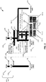
- FIG. 1 a metro-overlay system with an MPTCP-based (e.g., in accordance with RFC 6824 published by the IETF) aggregation solution may be used as shown in FIG. 1 .
- the MPTCP aggregation layer 116 may aggregate across macro cells 140 (of which macro cells 140-1 and 140-2 are shown), metro cells (of which one 5G metro cell 150 is shown) and standalone WiFi hotspots (e.g., access point 160), including 5G New Radio (NR) interfaces (see 5G new waveform macro cell 140-2).
- NR 5G New Radio
- the MPTCP aggregation layer 116 allows all bands to be aggregated and utilized effectively, driven by, e.g., a flow routing policy engine 120. Additionally, the MPTCP aggregation layer 116 is assumed to take IP traffic from the EPC 198 (e.g., over the S1-U interface).
- the UE 110 communicates with the 5G metro cell 150 and typically one of the LTE macro cell 140-1 or the 5G new waveform macro cell 140-2.
- a home gateway for a RAN plays a similar role as UE in a cellular system. Instead of the UE, which consumes traffic delivered by RAN itself, a home gateway instead routes traffic delivered by the RAN toward home devices such as TV and the like.
- reference 110 will be called a UE, and the term "user equipment" is intended to encompass a home gateway or other element that can benefit from the multiple air interface aggregation techniques as described herein.
- the UE 110 communicates with one of the LTE macro cell 140-1 or the 5G macro cell 140-2 using carrier aggregation (CA), as indicated by macro LTE CA 112.
- CA carrier aggregation
- the UE 110 communicates with the 5G metro cell via CA, as indicated by the metro LTE CA 114. Both of these go through PDCP layer aggregation 122 and to IP layer aggregation 118.
- the UE 110 may also communicate with the non-LWA WiFi access point (AP) 160. Both the AP 160 and 5G metro cell 150 may communicate with the UE 110 using the IP-sec secured link 190.
- the UE client 198 is an IP layer entity at the UE 110 that will access two APNs (shown in, e.g., FIG. 4 ).
- the 5G metro cell 150 comprises the following in this example: a 5G at (@) 28 GHz lower baseband FEU 156 and a corresponding 28 GHZ radio 155; an LWA Wi-Fi or LET-U/LAA or MuLTEfire baseband 157 and a corresponding 5.8 GHz radio 154; an LTE @ 3.5 GHz ⁇ 3x carriers lower baseband FEU, 5.8 GHz LTE-U with carrier aggr. (aggregation) 157 that is connectable to both the 5.8 GHz radio 154 and the 3.5 GHz radio 153.
- Reference 151 indicates LTE-U used for carrier aggregation.
- Reference 158 indicates a feedback link from low band for 28 GHz control (i.e., beam selection).
- Reference 159 indicates a link for LTE-U (e.g., carrier aggregation).
- Reference 180 indicates a possible link for LWA.
- the LTE macro cell 140-1 comprises an LTE at (@) low band lower baseband FEU with (w/) carrier aggregation 142 and multiple radios/carriers 144.
- the 5G macro cell 140-2 comprises a 5G FEU 132 and a 5G radio. Reference 131 for the 5G macro cell 140-2 indicates carrier aggregation.
- a CloudRAN SU 115 is also illustrated, and this can communicate with the AP 160 through firewall 170-1 and with the 5G metro cell 150 through the firewall 170-2.
- the CloudRAN SU 115 may also communicate with the LTE macro cell 140-1 and the 5G macro cell 140-2.
- the CloudRAN SU 115 comprises an MPTCP aggregation layer 116 and an upper baseband LTE/5G (PDCP layer aggregation) layer 117, and the layers 116 and 117 may be formed as part of a virtual eNB 118.
- the CloudRAN SU 115 may implement a flow routing policy engine 120, e.g., as part of the MPTCP aggregation layer 116.
- the CloudRAN SU 115 is an edge entity in an example, which operates at a point where traffic goes to the cluster of cells 140 and 150.
- the MPTCP aggregation layer 116 and its functionality may also be referred to as an MPTCP proxy, which runs on an edge entity, in this case the CloudRAN SU 115.
- the CloudRAN SU 115 may also be referred to as MPTCP proxy.
- the edge entity runs on the edge of the cluster of cells 140, 150 and intercepts S1-U interface (e.g., GTP) traffic and needs to associate peers of a TCP session and corresponding S1-U tunnels (TEID).
- S1-U interface e.g., GTP
- the entity that performs the MPTCP aggregation is not limited to a CloudRAN SU and may be other suitable entities. In the figures that follow, this entity is described as an MPTCP proxy.
- the CloudRAN SU communicates with the EPC 195, as described in more detail below.
- the cell makes up part of an eNB. That is, there can be multiple cells per eNB. For instance, there could be three cells for a single eNB carrier frequency and associated bandwidth, each cell covering one-third of a 360 degree area so that the single eNB's coverage area covers an approximate oval or circle.
- each cell can correspond to a single carrier and an eNB may use multiple carriers. So, if there are three 120 degree cells per carrier and two carriers, then the eNB has a total of six cells.
- macro cells 140 will also be referred to as MeNBs 140 or macro eNBs 140
- metro cells 150 will also be referred to as SeNBs 150 or metro eNBs 150.
- the MPTCP aggregation layer 116 (or other MPTCP proxy) is able open two TCP subflows (one over the MeNB, one over the SeNB) to the same UE IP address (IP-addr).
- the MPTCP is able to detect the tunnel ID TEIDs, without any assistance from the MeNB 150, thus allowing a metro overlay solution to be realized with peak aggregate throughputs across macros and metros with no assistance from, or coordination with, the macro eNB 150.
- peak HetNet capacity may be delivered in a metro overlay solution, with traffic and radio resource management under control of the metro vendor in a macro network controlled by another vendor.
- the peak HetNet capacity may be characterized by peak aggregate throughputs that use the capacity of macro cells and metro cells simultaneously for a single flow.
- Dummy bearers are defined to allocate tunnels that are used by the MPTCP proxy and not used by the core network. This allows the MPTCP proxy to make a split of two legs with no conflict with EPC logic.
- a TEID discovery procedure along with associated signaling (which does not require standardization) is introduced to assign a flow IP-addr to be assigned to a tunnel.
- the MPTCP proxy at the network should know the individual TEIDs associated with the bearers going over the MeNB 140 and the SeNB 150 in order to be able to split traffic arriving over a single eRAB (APN1).
- MPTCP needs to detect TEID change when bearer (APN2) is moved toward the SeNB.
- the unique TEID discovery mechanism at the MPTCP without any information provided by the MeNB 140, allows for the exemplary embodiments to deliver the described benefits.
- a technique used herein involves obtaining two IP addresses for the UE.
- a bearer is assigned to each IP address.
- IP1, IP2 the bearers associated with two ip-addr
- DC-1A logic at the MeNB 140 would move bearers between eNBs (e.g., from the MeNB 140 to the SeNB 150). In this case, the TEIDs of the bearers are changed, but IP addresses are not affected.
- the UE client 198 does not see if bearer was moved because the client still sees IP1, IP2 (IP addresses assigned and corresponding to the UE), independent of the fact that the bearer that carried IP2 was moved between eNBs.
- IP1, IP2 IP addresses assigned and corresponding to the UE
- IP2 IP addresses assigned and corresponding to the UE
- the tunnel id (TEID) associated with each bearer changes as the tunnel moves between MeNB and SeNB, and the specific TEID must be made visible to the MPTCP proxy.
- the algorithm below addresses all aspects of the above principles needed to make this work. For ease of reference, the rest of this disclosure is separated into different sections.
- FIG. 2 shows a pictorial representation of a metro overlay implemented in a network with MPTCP-based aggregation, with the aggregation layer supported on the CloudRAN server unit (SU), which acts as an MPTCP proxy.
- the aggregation layer may also reside outside the CloudRAN (e.g., a Mobile Edge Computing, MEC, platform).
- FIG. 3 is a signaling diagram illustrating assignment of two different IP addresses per UE.
- the associated text for FIG. 3 describes an exemplary IP assignment mechanism.
- FIG. 4 and the text associated with this figure illustrate an exemplary call flow for the metro overlay operation.
- the algorithm describes operation of a macro overlay with DC-1A and MPTCP to achieve peak aggregate throughputs for a single flow.
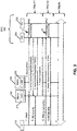
- FIG. 2 a metro overlay is implemented in the network 100 of FIG. 1 with MPTCP-based aggregation.
- FIG. 2 illustrates another view of the network 100 of FIG. 1 .
- the packet gateway (PGW) 220 and serving gateway (230) are shown (as part of the EPC 195), as are the interfaces that interconnect these and the incumbent macro eNBs 140.
- the S1-U is an interface used to interconnect the SGW 230 and the macro eNBs 140, and the S5/S8 interfaces are used to interconnect the SGW 230 and the PGW 220.
- the left-hand side illustrates a simple view of these connections and without macro overlay, while the right-hand side illustrates a more complex view of these connections, complete with multiple devices that use these interfaces via macro overlay.
- the CloudRAN SU 115 connects to the SGW 230 using the backhaul interface (I/F) 210, which terminates the S1-U interface from the SGW 230 and starts another S1-U interface toward the macro eNB 140. See reference 240.
- the MPTCP aggregation layer 116 of the CloudRan SU 115 aggregates multiple TCP sessions 290-1, 290-2, and 290-3 between the 5G metro FEU 150 and the standalone WiFi AP 160.
- the TCP session 290-1 also passes through the PDCP aggregation layer 117.
- the MPTCP aggregation layer 116 also aggregates information from the macro eNBs 140. The aggregation occurs through the switched IP/Ethernet midhaul 245.
- the MPTCP aggregation layer 116 operates in the IP layer.
- the MPTCP aggregation layer 116 intercepts S1-U (GTP) traffic, decapsulates the GTP traffic, performs MPTCP actions and encapsulates IP packets to GTP to deliver to an eNB where the PDCP layer is running.
- GTP S1-U
- the 5G metro cell 150 includes in this example the LTE-U baseband 157-1, an LAA baseband 157-2 and an MuLTEfire baseband 157-3, an LTE 250, a WiFi 260, and an mmW 270. These are different RATs (radio access technologies) that can be used in a metro cell. These are merely exemplary and fewer, more, or different RATs may be used.
- Connection by a UE to two APNs is a standard feature and the connection works the same way independent of if DC-1A feature is present or not.
- This is a legacy way for operators provide services specific to the operators to users.
- a separate APN may be used that assigns an IP-addr from an IMS sub-net to the UE and assigns an IP address that is routable in the Internet to all other traffic.
- a GBR QCI1 bearer is used for RTP traffic between the IMS and the UE (e.g.. using IP1) and a default QCI5 is used for all other traffic between the UE (e.g., using IP2) and the Internet.
- Another example is video services, where there is a separate APN which assigns a UE IP-addr from a video server sub-net, while all other traffic is from the Internet, where the UE is visible with another IP-addr.
- FIG. 3 is a signaling diagram illustrating assignment of two different IP addresses per UE 110, in accordance with an exemplary embodiment.
- FIG. 3 illustrates the control plane procedures Attach and PDP connectivity, and this figure illustrates how IP addresses are assigned.
- UE 110, M-RRM 310 (as part of a macro cell 140), m-RRM 320 (as part of the metro cell 150), MME 350, and SGW 230 are shown.
- the M-RRM is the radio resource management (RRM) in a macro cell 140.
- the m-RRM 310 is the RRM in the 5G metro cell 150.
- Step A1 at the initial attach (see step 1), the UE connects to APN1, and is assigned with IP1 (an IP address) in this PDN connection. After an attach, a single default bearer (e.g., eRAB1 (TEID1)) is created to transfer packets to the IP address IP1. More completely, Step A1 includes steps 1-7.
- step 1 there is an initial Attach message from the UE 110 to the APN1.
- step 2 There is an Attach (APN1) message in step 2 that is sent from the M-RRM 310 to the MME 350.
- the MMM 350 communicates with the SGW 230 via at least a Create Session (APN1) message in step 3.
- step 4 the MME 350 responds to the APN1 350 with an Initial Context Request (Req) message with an (eRAB1 (default)) indication.
- step 5 RRC Reconfiguration (Reconfig) messaging occurs between the UE 110 and the APN1 360.
- step 6 the M-RRM 310 sends an Initial Context Response (Rsp) with an (eRAB1(default-TEID1)) to the MME 350. Every bearer created at Attach time is identified with a TEID.
- the TEID is sent with a GTP packet directed to the eNB to be passed to the UE.
- the TEID allows the eNB to associate the packet with UE context and to manage the packet properly.
- step 7 the M-RRM sends an Attach Complete () message to the MME 350. Note that this sequence of steps also allows the MME 350 and the APN1 360 to have a first tunnel endpoint identifier (TEID1).
- TEID1 first tunnel endpoint identifier
- the UE 110 should issue a PDN_Connectivity Request (Req). That is, to make the UE connect to another APN and to be assigned with second IP-addr, a PDP Connectivity request is used by UE (instead of attach)
- the PDP Connectivity Request message is initiated on UE by the MPTCP client 198 or would be done manually by the user.
- eRAB TEID2
- the sequence of steps in Step A2 includes steps 8-11.
- the UE 110 issues a PDN Connectivity Request (Req) message to the MME 350.
- APN2 Create Session
- SGW 230 Another RRC Reconfiguration (Reconfig) messaging occurs in step 10, which is where the UE is assigned the IP2 address.
- Bearer Setup eRAB2 communication occurs with the indication (dummy, TEID2).
- the APN1 360 and the MME 350 also have another TIED, TEID2 assigned to the UE 110.
- Step A3 other communications occur between these elements.
- IP addresses assigned the UE are used by other elements in the system to connect to and contact the UE. These two IP addresses are used below for two bearers, with each IP address associated with a bearer.
- FIG. 4 is used to illustrate, among other things, establishing dummy bearers.
- FIG. 4 illustrates control and user planes. Major steps taken are as follows: Step A involves IP assignment; Step E involves traffic flow over single AP; Steps F-H involve the UE moving into the control plane of the metro cell; and Step I involves traffic split between the macro and metro user planes. Until step F, both bearers go through the macro eNB and are served at the M-RRM. At step F, the UE moves into micro coverage and the "dummy" bearer is moved to the micro cell. From this point, the macro cell supports one bearer toward the UE and the micro cell supports one bearer.
- the MPTCP proxy 430 decides how to split traffic between the bearers and address packets to the macro cell and to the micro cell.
- the MPTCP proxy 430 includes the MPTCP aggregation layer 116 and may also include other functionality.
- the MPTCP proxy 430 may be a complete traffic steering engine. Such traffic steering may be represented as more complex entity, where the traffic steering may be a part of a HetNet scheduler engine, which is responsible for leg connectivities and traffic steering on various layers.
- the HetNet scheduler engine can include the following: HN-LM - link management to maintain radio legs toward UE connectivity; TE-SWI - Traffic Switching - Traffic steering engine that operates on an IP layer; and TR_Spl - Traffic Splitting - Traffic Steering engine that operates on the PDCP layer.
- HN-LM - link management to maintain radio legs toward UE connectivity
- TE-SWI - Traffic Switching - Traffic steering engine that operates on an IP layer
- TR_Spl - Traffic Splitting - Traffic Steering engine that operates on the PDCP layer.
- the CloudRAN SU 115 is one possible way to implement the MPTCP proxy 430.
- An operator model defines "dummy" bearers, which are used to support, e.g., DC-1A logic at the UE and the eNBs.
- the UE is provided with two bearers: the default and dedicated (dummy) bearers.
- the EPC 195 always directs traffic over the single default bearer.
- the TFT will not select any flow to bind to the "dummy" bearer so EPC 195 sends no packets toward the "dummy" bearer.
- the UE attaches to MeNB (APN1 360) and two bearers are created by connecting to two different APNs (APN1 360 and APN2 370).
- Connectivity to two APNs means that the UE 110 is connected to two different networks and is reachable in every network with a unique IP address (IP-addr) assigned to the UE for each network.
- IP-addr IP address assigned to the UE for each network.
- Use of additional APN in scheme DC-1A allows having different IP addresses for bearer 1 (ip1) and bearer2 (ip2).
- bearer 2 on APN2 is configured in a way that the EPC does not send traffic over this bearer (which is why it is called a "dummy bearer").
- step A1 attach and PDP Connectivity Request (Req) procedures are performed.
- the UE performs the attach to APN1 and is assigned with the default bearer.
- the UE performs PDN Connectivity_Req (a connectivity request) to APN2 and is assigned the dummy bearer.
- the IP addresses IP1 and IP2 are assigned to default and dummy bearers, respectively. Both the ⁇ IP1, IP2 ⁇ are visible for the MPTCP client in the UE 110. See block 405.
- TEID1 is assigned for the default bearer (bearer 1) for DL
- TEID2 is assigned for the dummy bearer (bearer2) for DL.
- the M-RRM 310 hosts both TEID1 (IP1) and TEID2(IP2).
- Block 415 indicates that TEIDEPC1 is assigned to the default bearer for UL.
- Block 420 indicates that TEIDEPC2 is assigned to the dummy bearer for UL.
- the APN1 360 hosts TEIDEPC1, and the APN2 370 hosts the TEIDEPC2. Note that the right side of the diagram is considered to be other parts of the EPC 195, illustrated here as being the S1-U interface 410.
- the MPTCP proxy learns the TEIDEPC1 from UL packet IP1 and takes TEID1 from TCP setup ACK (acknowledge).
- the UE is assigned IP2 and issues add_subflow(IP2).
- IP2 is known at this point to the MPTCP proxy (e.g., MPTCP aggregation layer 116).
- STEP B is triggered when the UE 110 is going to set up any TCP session with a network application.
- MPTCP procedures are used, as follows: setup and add_sub-flow (STEPS B and C) are performed. These procedures are supported by MPTCP proxy 430 at the RAN edge.
- MPTCP proxy 430 works with inner GTP packets (e.g., packets sent by the UE to its application) and initially does not know which eNB ip-addr and GTP TEID correspond to which inner packet ip-addr. From procedure messages, the MPTCP proxy determines information about IP1, IP2 of the same UE and that TEIDs for IP1.
- the MPTCP proxy 430 starts a tunnel discovery procedure for IP2 to determine the TEID2 of the dummy bearer.
- the MPTCP proxy 430 is stand-alone function which is not privy to any information over LTE control plane procedures. Instead, the MPTCP proxy 430 intercepts user plane interface and creates needed UE associations using some OTT (over the top) procedures.
- OTT over the top
- This port is the only port configured for DL on the dummy bearer.
- the port is configured by means of setting a static PCC rule for this APN.
- APN is set up at the PGW (e.g., at system configuration time)
- all APN parameters are configured, including ip-pool addresses, PCC rules to classify and charge traffic, and the like.
- the packet is routed on the Gi interface from APN1 to APN2 and arrives back to the MPTCP proxy 430 over a dummy tunnel.
- MPTCP proxy 430 knows TEID2 (and, as indicated, IP1, IP2, and TEID1).
- all data related to UE transport is typically a tuple, such as the following: ⁇ IP1, TEID1, IP2, TEID2 ⁇ .
- the former tuple is used to simplify tuple representation.
- the tunnel to send a message to the UE is a combination of eNB-ip + bearer TEID.
- a more complete set of attributes to be maintained for such a tunnel is a 6-tuple: ⁇ ue_ip1, eNB_ip1, TEID1; ue_ip2, eNB_ip2, TEID2 ⁇ .
- Ue_ip1 we need to send a packet to eNB_ip1.
- a user packet to send should be encapsulated to GTP with TEID set in the GTP header.
- the MPTCP proxy 430 sends a packet to IP2 through network (STEP D).
- the packet is routed the following way: MPTCP proxy 430 toward APN1 360 toward the data network (Internet, e.g., through the S1-U 410) toward the APN2 370 toward the MPTCP proxy 430.
- the inner packet is encapsulated to GTP with TEID2 in the header and with SeNB ip-addr as the destination address. So, the MPTCP proxy 430 would complete the tuple creation, as the MPTCP proxy 430 now knows TEID2.
- the MPTCP proxy knows all transport attributes and knows that both tunnels are terminated at the same eNB. It is up to the MPTCP proxy 430 if a single TCP sub-flow or two subflows should be used (as there may be no benefit on using two subflows over the same eNB).
- IP1 and IP2 which are assigned to the UE 110.
- the former one is associated with Bearer1 and the latter one with Bearer2.
- both bearers go through the M-eNB 140 and have the corresponding TEIDs of TEID1 and TEID2.
- a bearer is a concept. In other words, a bearer is associated with a set of parameters, including QoS to treat packets to be transported.
- a tunnel - typically using GTP (General Tunnel Protocol) - is a means to transfer packets that have the same QoS treatment.
- UE Context is created and maintained at the eNB and PGW.
- bearer context is created and associated with UE context.
- Bearer context includes one or more of the following: classification rules (rules to associate arrived packets to distinct bearer), QoS parameters, and tunnel parameters.
- Tunnel parameters may include the following: eNB ip_addr; and TEID.
- the eNB ip_addr- is the IP address of the eNB that serves UE at a given time.
- the TEID is a unique identifier, assigned by the eNB, to make the eNB associate packets arrived over a tunnel with UE context and bearer context. In other words, when a packet arrives, the eNB will have to serve the packet at the air based on the rules kept at the UE-bearer context.
- the MPTCP proxy 430 receives DL TCP packets from the EPC 195 over Bearer1 440-1 and would decide to split it to two sub-flows directed toward Bearer1 440-2 and Bearer2 450.
- the MPTCP proxy 430 e.g., with Intelligent Traffic Control (ITC), uses two sub-TCP legs to go to known TEIDs toward the macro cell 140 and the micro cell 150.
- the MPTCP proxy 430 may use an optional third leg (WiFi) of traffic and split traffic between 3GPP and non-3GPP legs.
- WiFi third leg
- the policy used by the MPTCP proxy 430 to split TCP over LTE legs would conflict with EPC policies regarding which bearer is used for which services.
- a "dummy" bearer is defined, with no traffic mapped to the dummy bearer on EPC side.
- two tunnels e.g., over Bearers 1 440-2 and 450
- the service-to-leg binding decision is made by a single entity, the MPTCP proxy 430.
- STEP E traffic from the Bearer1 440-1 is split by the MPTCP proxy 430 toward two tunnels and goes through the MeNB (the macro cell 140) as both tunnels are still at the MeNB 140.
- STEP E indicates that the tunnel 440-2 (corresponding to the default bearer, Bearer1) and tunnel 450 (corresponding to the dummy bearer, Bearer 2) are both routed to the MeNB 140 from the MPTCP proxy 430.
- Traffic always goes over the default bearer 440 in relation to the core network, as policies of second bearer 450 do not select any flow in the core network.
- ip2 is the IP address assigned to UE when the UE performed the PDP_Connection toward APN2. See STEP C.
- the ip1 and ip2 arc the two IP addresses assigned to UE, and inside the UE, these addresses are relayed to two IP interfaces.
- the MPTCP Proxy intercepts this TCP session and organizes three TCP sessions instead: (1) UE_ip1 to and from the MPTCP Proxy; (2) UE_ip2 to and from the MPTCP Proxy; and MPTCP Proxy to and from networkApp_ip over APN1 toward network.
- UE client application 198 is unaware about these multiple sessions and "thinks" there is a single client-to-network-application session.
- Packets from the network application to the client application 198 are sent toward MPTCP proxy assigned ip-addr. This session is terminated at the MPTCP proxy (see STEP E).
- the MPTCP proxy 430 sends packets received through APN1 to the UE over one of the two tcp_sub-flow (sub-sessions): MPTCP->ip1 (440-1) or MPTCP->ip2 (450).
- the MPTCP proxy 430 decides what subflow on which the packet should be sent based on TCP flow control, which controls each subflow. So, if a tcp-window on subflow1 indicates more packets ACKed then window of subflow2, MPTCP sends the packet over subflow1, and vice versa.
- the MPTCP proxy 430 knows which tunnel to use to send packets on sub-flowl (IP1) and which for IP2.
- IP1 sub-flowl
- the MPTCP proxy would use a flow control mechanism to steer traffic over legs as well some extra policies would be used to make the MPTCP proxy 430 decide which TCP packet is to be sent over which sub-flow. This allows for implementing various policies within the MPTCP proxy 430 regarding traffic distribution between the macro and micro cells.
- MPTCP should know the TEIDs associated with the individual bearers (one default bearer, and one dedicated bearer).
- the default bearer always passes through the MeNB and maintains the same TEID1.
- the dedicated bearer when passing through the MeNB has a TEID2, and when the dedicated bearer is moved to the SeNB acquires a new TEID namely TEID3.
- the MPTCP proxy 430 When a TCP-connect arrives at the MPTCP proxy 430, say over TEID1, the MPTCP proxy 430 should know if Bearer2 exists and know its TEID2, to make any decision. It should run a TEID discovery procedure (see STEP D) every time an add/delete TCP-subflow operation is triggered and/or every time a TEID for a distinct leg is changed due to bearer move to/from SeNB. Details of the TEID discovery are described in STEP D of FIG. 4 and also text above with respect to STEP D. STEP H is another TEID discovery procedure.
- the UE reports good cells via the RRM Reporting in STEP F. This reporting indicates the appearance of the SeNB 150. This means it is possible for the UE to also receive information from the SeNB 150.
- MeNB RRM
- DC-1A mechanism moves Bearer2 (IP2) to SeNB.
- IP2 Bearer2
- the MeNB RRM moves the "dummy" bearer to SeNB (using standard X2App procedures).
- STEP F This is illustrated by STEP F, where the DC-1A (by M-RRM in MeNB 140) moves the dummy bearer to m-RRM 320.
- a standard DC procedure is used in STEP F, as basically a relatively simple set of messages. However, the procedure is more complex, as follows.
- the UE had measured the metro cell 150 and reports to M-RRC via RRM reporting.
- the macro cell 140 issues an RRC command to the UE to join the metro cell 150.
- the SeNB 150 decided based on available resources how the SeNB can help the MeNB. Two options are available: "split DC-3C" and "move DC-1A".
- the SeNB 150 is in this example configured to choose DC-1A.
- the DC-1A creates a new TEID within SeNB and responds to MeNB with Add-SeNB-response (with the new TEID passed via this message).
- the MeNB communicates to the MME with a "modify bearer" message including the new TEID assigned by the SeNB.
- the MME communication continues toward PGW (APN2).
- PGW PGW
- the TEID2 on the M-RRM 310 stops working, and the TEID3 assigned to m-RRM is a termination for the dummy bearer now.
- Appropriate changes are made in APN2 370.
- the TEID3 replaces the TEID2 in the dummy bearer context.
- the UE 110 sends RRM reporting to the macro cell 140.
- the macro cell 140 communicates with the metro cell 150, and the metro cell 150 communicates with the APN2.
- the end result of these communications is indicated as follows.
- the TEID1 is active for the default bearer and the TEID2 for the dummy bearer is removed.
- the metro cell 150 now has TEID3 for the dummy bearer.
- the TEID3 replaces TEID in the dummy bearer context.
- the MPTCP proxy 430 autodetects the TEID3 associated with the dummy bearer that has moved to the SeNB as described in STEP H (see also the description of STEP D above).
- the MPTCP proxy 430 is able to open two TCP subflows (one to the macro cell 140, one to the metro cell 150). Thereafter, the MPTCP proxy 430 will encapsulate the TCP subflow into the proper GTP tunnel TEID3.
- the second TEID discovery procedure in STEP H is triggered by STEP G, where the MPTCP proxy 430 detects no ack (acknowledgement) from sub-flow IP2 (TEID2). See reference 467. Note that there may be a time period associated with this, e.g., such that no acks received within a time period would trigger STEP H actions.
- the special UDP message is labeled this way because of the following.
- the MPTCP proxy 430 sends the message to IP2, and the message will go to the network over APN1 and will be returned (routed) back over APN2.
- the PGW (APN2) will send the message to the SeNB ip-addr and place the TEID-SeNB into the GTP header.
- the MPTCP proxy When traffic arrives at the MPTCP proxy over MeNB S1U (default bearer), the MPTCP proxy sends packets toward two TEIDs (TEID1, TEID3) over two TCP legs, one over the MeNB and one over the SeNB. Thus, MPTCP splits packets of a traffic flow, or the flows themselves over two TEIDs. At this point two TCP subflows (subflowl and subflow2) will go over two legs Macro and metro.
- the TCP subflow goes to tunnel TEID3 (tunnel 470, corresponding to the dummy bearer) owned by m-RRM 320, and the TCP subflow (IP1) goes to the tunnel TEID1 (tunnel 440, corresponding to the default bearer) owned by M-RRM 310.
- Subflowl and subflow2 therefore go over to the macro cell 140 and micro cell 150, respectively.
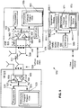
- FIG. 5 this figure is a block diagram of one possible and non-limiting exemplary system in which the exemplary embodiments may be practiced.
- a user equipment (UE) 110 is in wireless communication with a wireless network 500.
- Network 500 is one view of the network 100.
- a UE 110 is a wireless, typically mobile device that can access a wireless network.
- the UE 110 includes one or more processors 520, one or more memories 525, and one or more transceivers 530 interconnected through one or more buses 527.
- Each of the one or more transceivers 530 includes a receiver, Rx, 532 and a transmitter, Tx, 533.
- the one or more buses 527 may be address, data, or control buses, and may include any interconnection mechanism, such as a series of lines on a motherboard or integrated circuit, fiber optics or other optical communication equipment, and the like.
- the one or more transceivers 530 are connected to one or more antennas 528.
- the one or more memories 525 include computer program code 523.
- the one or more memories 525 and the computer program code 523 may be configured to, with the one or more processors 520, cause the user equipment 510 to perform one or more of the operations as described herein.
- the UE 110 communicates with eNB 570 via a wireless link 511.
- the eNB (evolved NodeB) 570 (such as one of the MeNB 140 or SeNB 150) is a base station (e.g., for LTE, long term evolution) that provides access by wireless devices such as the UE 110 to the wireless network 500.
- the eNB 570 includes one or more processors 552, one or more memories 555, one or more network interfaces (N/W I/F(s)) 561, and one or more transceivers 560 interconnected through one or more buses 557.
- Each of the one or more transceivers 560 includes a receiver, Rx, 562 and a transmitter, Tx, 563.
- the one or more transceivers 560 are connected to one or more antennas 558.
- the one or more memories 555 include computer program code 553.
- the one or more memories 555 and the computer program code 553 are configured to, with the one or more processors 552, cause the eNB 570 to perform one or more of the operations as described herein.
- the one or more network interfaces 561 communicate over a network such as via the links 576 and 531.
- Two or more eNBs 570 communicate using, e.g., link 576.
- the link 576 may be wired or wireless or both and may implement, e.g., an X2 interface.
- the one or more buses 557 may be address, data, or control buses, and may include any interconnection mechanism, such as a series of lines on a motherboard or integrated circuit, fiber optics or other optical communication equipment, wireless channels, and the like.
- the one or more transceivers 560 may be implemented as a remote radio head (RRH) 195, with the other elements of the eNB 570 being physically in a different location from the RRH, and the one or more buses 557 could be implemented in part as fiber optic cable to connect the other elements of the eNB 570 to the RRH 595.
- RRH remote radio head
- the wireless network 500 includes a number of additional entities, represented by element 590.
- the element 590 is used to represent multiple other elements.
- the element 590 is the MPTCP proxy 430.
- the element 590 is one of the MME 350, SGW 230, or PGW 220.
- the element may provide connectivity with a further network, such as a telephone network and/or a data communications network (e.g., the Internet).
- the eNB 570 may be coupled via a link 531 to the element 590.
- the link 531 may be implemented as, e.g., an S1 or other appropriate interface.
- the element 590 includes one or more processors 575, one or more memories 571, and one or more network interfaces (N/W I/F(s)) 580, interconnected through one or more buses 585.
- the one or more memories 571 include computer program code 573.
- the one or more memories 571 and the computer program code 573 are configured to, with the one or more processors 575, cause the NCE 590 to perform one or more operations.
- the MPTCP proxy 430/590 includes an aggregation module 550. comprising one of or both parts 550-1 and/or 550-2, which may be implemented in a number of ways.
- the aggregation module 550 may be implemented in hardware as aggregation module 550-1, such as being implemented as part of the one or more processors 575.
- the aggregation module 550-1 may be implemented also as an integrated circuit or through other hardware such as a programmable gate array.
- the aggregation module 550 may be implemented as aggregation module 550-2, which is implemented as computer program code 573 and is executed by the one or more processors 575.
- the aggregation module 550 would not be used, but those devices would have other programming or hardware to carry out the functions described herein.
- the wireless network 500 may implement network virtualization, which is the process of combining hardware and software network resources and network functionality into a single, software-based administrative entity, a virtual network.
- Network virtualization involves platform virtualization, often combined with resource virtualization.
- Network virtualization is categorized as either external, combining many networks, or parts of networks, into a virtual unit, or internal, providing network-like functionality to software containers on a single system. Note that the virtualized entities that result from the network virtualization are still implemented, at some level, using hardware such as processors 552 or 575 and memories 555 and 571, and also such virtualized entities create technical effects.
- the CloudRAN SU 115 in FIG. 1 is one possible entity that may be formed by network virtualization.
- the computer readable memories 525, 555, and 571 may be of any type suitable to the local technical environment and may be implemented using any suitable data storage technology, such as semiconductor based memory devices, flash memory, magnetic memory devices and systems, optical memory devices and systems, fixed memory and removable memory.
- the computer readable memories 525, 555, and 571 may be means for performing storage functions.
- the processors 520, 552, and 575 may be of any type suitable to the local technical environment, and may include one or more of general purpose computers, special purpose computers, microprocessors, digital signal processors (DSPs) and processors based on a multi-core processor architecture, as non-limiting examples.
- the processors 520, 552, and 575 may be means for performing functions, such as controlling the UE 110, eNB 570, and element 590, and for performing other functions as described herein.
- FIG. 6 a logic flow diagram is shown for multiple air interface aggregation supporting multivendor 4G/5G networks.
- FIG. 6 illustrates the operation of an exemplary method or methods, a result of execution of computer program instructions embodied on a computer readable memory, functions performed by logic implemented in hardware, and/or interconnected means for performing functions in accordance with exemplary embodiments. It is assumed the blocks of FIG. 6 are performed by a network element, such as the MPTCP proxy 430, under control of the aggregation module 550. However, other network elements are also possible.
- the network element provides an interface in a wireless network between base stations and a core network.
- the network element determines a first tunnel endpoint identifier associated with a default bearer between a user equipment and a first access point name.
- the network element determines whether a tunnel discovery procedure should be performed to discover a second tunnel endpoint identifier associated with a dummy bearer.
- the dummy bearer is associated with the user equipment and a second access point name, and the default and dummy bearers are different.
- the network element performs, in response to a determination the tunnel discovery procedure should be performed, the tunnel discovery procedure to discover the second tunnel endpoint identifier associated with the dummy bearer.
- the network element in block 640 sets up the dummy bearer between the network element and the user equipment.
- the network element in block 650 routes data arriving at the network element from the core network and toward the user equipment over one of the default bearer, using the first tunnel endpoint identifier, or the dummy bearer, using the second tunnel endpoint identifier.
- the network element routes data arriving at the network element from the user equipment and toward the core network over only over the default bearer.
- PGW e.g., APN1
- the MPTCP proxy 430 intercepts the tunnel, takes a packet with information ⁇ MeNB-ip, TEID1 ⁇ ⁇ ip1, tcp ⁇ and makes a decision which tunnel towards the UE should be used to route the packet.
- the MPTCP proxy 430 sends the packet to ⁇ MeNB-ip, TEID1 ⁇ ⁇ ip1, tcp ⁇ over the default bearer. If the decision is to route the packet to tcp_sub-flow2, the MPTCP proxy 430 forms the packet: ⁇ SeNB_ip, TEID2 ⁇ ⁇ ip2, tcp ⁇ to route the user tcp packet over the dummy bearer.
- the MPTCP proxy 430 makes a routing decision and substitutes ⁇ eNB-ip;TEID ⁇ ⁇ UE_ip ⁇ in the source packet based on this decision.
- the MPTCP proxy 430 forms the packet: ⁇ MeNB_ip, TEID2 ⁇ ⁇ ip2, tcp ⁇ to route the user tcp packet over the dummy bearer.
- a technical effect of one or more of the example embodiments disclosed herein is the ability to add metro cells from one vendor to areas controlled by macro cells controlled by another vendor. Another technical effect of one or more of the example embodiments disclosed herein is an improvement in overall system capacity, such that the over system capacity may be improved. Another technical effect of one or more of the example embodiments disclosed herein is providing maximal HetNet capacity with a metro overlay solution with no assistance from the macro eNB.
- Embodiments herein may be implemented in software (executed by one or more processors), hardware (e.g., an application specific integrated circuit), or a combination of software and hardware.
- the software e.g., application logic, an instruction set
- a "computer-readable medium” may be any media or means that can contain, store, communicate, propagate or transport the instructions for use by or in connection with an instruction execution system, apparatus, or device, such as a computer, with one example of a computer described and depicted, e.g., in FIG. 5 .
- a computer-readable medium may comprise a computer-readable storage medium (e.g., memories 525, 555, 571 or other device) that may be any media or means that can contain, store, and/or transport the instructions for use by or in connection with an instruction execution system, apparatus, or device, such as a computer.
- a computer-readable storage medium does not comprise propagating signals.
- the different functions discussed herein may be performed in a different order and/or concurrently with each other. Furthermore, if desired, one or more of the above-described functions may be optional or may be combined.
Landscapes
- Engineering & Computer Science (AREA)
- Computer Networks & Wireless Communication (AREA)
- Signal Processing (AREA)
- Computer Security & Cryptography (AREA)
- Databases & Information Systems (AREA)
- Mobile Radio Communication Systems (AREA)
Claims (28)
- Procédé, comprenant :la détermination, au niveau d'un élément de réseau (430) qui fournit une interface dans un réseau sans fil entre des stations de base (140, 150) et un réseau central, d'un premier identifiant de point d'extrémité de tunnel associé à un support par défaut entre un équipement utilisateur (110) et un premier nom de point d'accès (360) ;la détermination, au niveau de l'élément de réseau (430), de la nécessité ou non de réaliser une procédure de découverte de tunnel pour découvrir un deuxième identifiant de point d'extrémité de tunnel associé à un support fictif, le support fictif étant associé à l'équipement utilisateur (110) et à un deuxième nom de point d'accès (370), dans lequel les supports par défaut et fictif sont différents ;la réalisation, au niveau de l'élément de réseau (430) et en réponse à une détermination de la nécessité de réaliser la procédure de découverte de tunnel, de la procédure de découverte de tunnel pour découvrir le deuxième identifiant de point d'extrémité de tunnel associé au support fictif ;l'établissement, au niveau de l'élément de réseau (430), du support fictif (450) entre l'élément de réseau (430) et l'équipement utilisateur (110) ;l'acheminement, par l'élément de réseau (430), de données arrivant dans l'élément de réseau (430) depuis le réseau central et vers l'équipement utilisateur (110) sur l'un parmi le support par défaut, en utilisant le premier identifiant de point d'extrémité de tunnel, ou le support fictif, en utilisant le deuxième identifiant de point d'extrémité de tunnel ; etl'acheminement, par l'élément de réseau (430), des données arrivant dans l'élément de réseau (430) depuis l'équipement utilisateur (110) et vers le réseau central uniquement sur le support par défaut.
- Procédé de la revendication 1, dans lequel :le support par défaut est associé à une première adresse de protocole Internet attribuée à l'équipement utilisateur (110) ;la détermination de la nécessité ou non de réaliser une procédure de découverte de tunnel pour découvrir un deuxième identifiant de point d'extrémité de tunnel associé à un support fictif détermine que la procédure de découverte de tunnel doit être réalisée en réponse à une demande par l'équipement utilisateur (110) d'ajouter un sous-flux correspondant à une deuxième adresse de protocole Internet attribuée à l'équipement utilisateur (110) ; etle procédé comprend en outre l'association de la deuxième adresse de protocole Internet au support fictif.
- Procédé de l'une quelconque des revendications 1 et 2, dans lequel :
l'acheminement des données arrivant dans l'élément de réseau (430) depuis le réseau central et vers l'équipement utilisateur (110) sur l'un parmi le support par défaut ou le support fictif achemine des données sur le support par défaut vers une station de base unique, et achemine des données sur le support fictif vers la station de base unique. - Procédé de la revendication 3, dans lequel la station de base est une station de base macro.
- Procédé de l'une quelconque des revendications 1 à 4, dans lequel :les données arrivant dans l'élément de réseau (430) depuis le réseau central et vers l'équipement utilisateur (110) ont une première adresse de protocole Internet qui est attribuée à l'équipement utilisateur (110) et qui est associée au support par défaut ;une deuxième adresse de protocole Internet est attribuée à l'équipement utilisateur (110) et est associée au support fictif ;le procédé comprend en outre la prise d'une décision d'acheminement, par l'élément de réseau (430), pour décider s'il faut acheminer les données sur le support par défaut ou sur le support fictif ;l'acheminement des données arrivant dans l'élément de réseau (430) depuis le réseau central et vers l'équipement utilisateur (110) sur l'un parmi le support par défaut ou le support fictif est réalisé en réponse à la décision d'acheminement ;l'élément de réseau (430) adresse les données acheminées sur le support par défaut à l'équipement utilisateur (110) en utilisant au moins une adresse de protocole Internet attribuée à une station de base unique, le premier identifiant de point d'extrémité de tunnel et la première adresse de protocole Internet ; etl'élément de réseau (430) adresse les données acheminées sur le support par défaut à l'équipement utilisateur (110) en utilisant au moins une adresse de protocole Internet attribuée à la station de base unique, le deuxième identifiant de point d'extrémité de tunnel et la deuxième adresse de protocole Internet.
- Procédé de la revendication 1, dans lequel :le support par défaut est associé à une première adresse de protocole Internet attribuée à l'équipement utilisateur (110) ;avant de déterminer si la procédure de découverte de tunnel doit être réalisée, des données entre l'équipement utilisateur (110) et l'élément de réseau (430) étaient acheminées en utilisant un identifiant de point d'extrémité de tunnel initial sur le support par défaut vers et depuis le réseau central, et sur un support fictif initial vers et depuis l'élément de réseau (430), dans lequel le support fictif initial est différent du support par défaut et du support fictif, et dans lequel le support initial est associé à une deuxième adresse de protocole Internet attribuée à l'équipement utilisateur (110) ;le procédé comprend en outre, avant de déterminer si la procédure de découverte de tunnel doit être réalisée, le fait de déterminer qu'aucun accusé de réception de protocole de contrôle de transmission n'a été reçu à partir de la deuxième adresse de protocole Internet ;la détermination de la nécessité ou non de réaliser une procédure de découverte de tunnel pour découvrir un deuxième identifiant de point d'extrémité de tunnel associé à un support fictif détermine que la procédure de découverte de tunnel doit être réalisée en réponse au fait de déterminer qu'aucun accusé de réception de protocole de contrôle de transmission n'a été reçu à partir de la deuxième adresse de protocole Internet ; etla réalisation de la procédure de découverte de tunnel est réalisée pour découvrir le deuxième identifiant de point d'extrémité de tunnel associé au support fictif, et associe le deuxième identifiant de point d'extrémité de tunnel découvert au support fictif ; etle procédé comprend l'association du support fictif à la deuxième adresse de protocole Internet attribuée à l'équipement utilisateur (110).
- Procédé de la revendication 6, dans lequel :
l'acheminement des données arrivant dans l'élément de réseau (430) depuis le réseau central et vers l'équipement utilisateur (110) sur l'un parmi le support par défaut ou le support fictif achemine des données sur le support par défaut vers une première station de base, et achemine des données sur le support fictif vers une deuxième station de base. - Procédé de la revendication 7, dans lequel la première station de base est une station de base macro et la deuxième station de base est une station de base métro.
- Procédé de l'une quelconque des revendications 6 à 8, dans lequel :les données arrivant dans l'élément de réseau (430) depuis le réseau central et vers l'équipement utilisateur (110) ont une première adresse de protocole Internet qui est attribuée à l'équipement utilisateur (110) et qui est associée au support par défaut, et le support par défaut est associé à une première station de base ;une deuxième adresse de protocole Internet est attribuée à l'équipement utilisateur (110) et est associée au support fictif, et le support fictif est associé à une deuxième station de base ;le procédé comprend en outre la prise d'une décision d'acheminement, par l'élément de réseau (430), pour décider s'il faut acheminer les données sur le support par défaut ou sur le support fictif ;l'acheminement des données arrivant dans l'élément de réseau (430) depuis le réseau central et vers l'équipement utilisateur (110) sur l'un parmi le support par défaut ou le support fictif est réalisé en réponse à la décision d'acheminement ;l'élément de réseau (430) adresse les données acheminées sur le support par défaut à l'équipement utilisateur (110) en utilisant au moins une adresse de protocole Internet attribuée à la première station de base, le premier identifiant de point d'extrémité de tunnel et la première adresse de protocole Internet ; etl'élément de réseau (430) adresse les données acheminées sur le support par défaut à l'équipement utilisateur (110) en utilisant au moins une adresse de protocole Internet attribuée à la deuxième station de base, le deuxième identifiant de point d'extrémité de tunnel et la deuxième adresse de protocole Internet.
- Procédé de l'une quelconque des revendications 1 à 9, dans lequel :le support par défaut est associé à une première adresse de protocole Internet attribuée à l'équipement utilisateur (110) ;le support fictif est associé à une deuxième adresse de protocole Internet attribuée à l'équipement utilisateur (110) ;la procédure de découverte de tunnel comprend :l'envoi d'un message vers le réseau central, le message indiquant la deuxième adresse de protocole Internet et une adresse de port qui est propre au support fictif ; etla réception d'une réponse à partir du réseau central, la réponse indiquant le deuxième identifiant de point d'extrémité de tunnel.
- Procédé de la revendication 10, dans lequel le message envoyé vers le réseau central comprend un message de protocole de datagramme utilisateur.
- Procédé de l'une quelconque des revendications 1 à 11, dans lequel l'élément de réseau (430) comprend un mandataire de contrôle de transmission par trajets multiples.
- Appareil comprenant :un moyen pour déterminer, au niveau d'un élément de réseau (430) qui fournit une interface dans un réseau sans fil entre des stations de base (140, 150) et un réseau central, un premier identifiant de point d'extrémité de tunnel associé à un support par défaut entre un équipement utilisateur (110) et un premier nom de point d'accès (360) ;un moyen pour déterminer, au niveau de l'élément de réseau (430), si une procédure de découverte de tunnel doit être réalisée pour découvrir un deuxième identifiant de point d'extrémité de tunnel associé à un support fictif, le support fictif étant associé à l'équipement utilisateur (110) et à un deuxième nom de point d'accès (370), dans lequel les supports par défaut et fictif sont différents ;un moyen pour réaliser, au niveau de l'élément de réseau (430) et en réponse à une détermination de la nécessité de réaliser la procédure de découverte de tunnel, la procédure de découverte de tunnel pour découvrir le deuxième identifiant de point d'extrémité de tunnel associé au support fictif ;un moyen pour établir, au niveau de l'élément de réseau (430), le support fictif entre l'élément de réseau (430) et l'équipement utilisateur (110) ;un moyen pour acheminer, par l'élément de réseau (430), des données arrivant dans l'élément de réseau (430) depuis le réseau central et vers l'équipement utilisateur (110) sur l'un parmi le support par défaut, en utilisant le premier identifiant de point d'extrémité de tunnel, ou le support fictif, en utilisant le deuxième identifiant de point d'extrémité de tunnel ; etun moyen pour acheminer, par l'élément de réseau (430), des données arrivant dans l'élément de réseau (430) depuis l'équipement utilisateur (110) et vers le réseau central uniquement sur le support par défaut.
- Appareil de la revendication 13, dans lequel :le support par défaut est associé à une première adresse de protocole Internet attribuée à l'équipement utilisateur (110) ;le moyen pour déterminer si une procédure de découverte de tunnel doit être réalisée pour découvrir un deuxième identifiant de point d'extrémité de tunnel associé à un support fictif comprend un moyen pour déterminer que la procédure de découverte de tunnel doit être réalisée en réponse à une demande par l'équipement utilisateur (110) d'ajouter un sous-flux correspondant à une deuxième adresse de protocole Internet attribuée à l'équipement utilisateur (110) ; etl'appareil comprend en outre un moyen pour associer la deuxième adresse de protocole Internet au support fictif.
- Appareil de l'une quelconque des revendications 13 et 14, dans lequel :
le moyen pour acheminer des données arrivant dans l'élément de réseau (430) depuis le réseau central et vers l'équipement utilisateur (110) sur l'un parmi le support par défaut ou le support fictif comprend un moyen pour acheminer des données sur le support par défaut vers une station de base unique, et un moyen pour acheminer des données sur le support fictif vers la station de base unique. - Appareil de la revendication 15, dans lequel la station de base est une station de base macro.
- Appareil de l'une quelconque des revendications 13 à 16, dans lequel :les données arrivant dans l'élément de réseau (430) depuis le réseau central et vers l'équipement utilisateur (110) ont une première adresse de protocole Internet qui est attribuée à l'équipement utilisateur (110) et qui est associée au support par défaut ;une deuxième adresse de protocole Internet est attribuée à l'équipement utilisateur (110) et est associée au support fictif ;l'appareil comprend en outre, dans l'élément de réseau (430), un moyen pour prendre une décision d'acheminement pour décider s'il faut acheminer les données sur le support par défaut ou sur le support fictif ;le moyen pour acheminer des données arrivant dans l'élément de réseau (430) depuis le réseau central et vers l'équipement utilisateur (110) sur l'un parmi le support par défaut ou le support fictif est une réponse à la décision d'acheminement ;l'appareil comprend, dans l'élément de réseau (430), un moyen pour adresser les données acheminées sur le support par défaut à l'équipement utilisateur (110) en utilisant au moins une adresse de protocole Internet attribuée à une station de base unique, le premier identifiant de point d'extrémité de tunnel et la première adresse de protocole Internet ; etl'appareil comprend, dans l'élément de réseau (430), un moyen pour adresser les données acheminées sur le support par défaut à l'équipement utilisateur (110) en utilisant au moins une adresse de protocole Internet attribuée à la station de base unique, le deuxième identifiant de point d'extrémité de tunnel et la deuxième adresse de protocole Internet.
- Appareil de la revendication 13, dans lequel :le support par défaut est associé à une première adresse de protocole Internet attribuée à l'équipement utilisateur (110) ;avant de déterminer si la procédure de découverte de tunnel doit être réalisée, des données entre l'équipement utilisateur (110) et l'élément de réseau (430) étaient acheminées en utilisant un identifiant de point d'extrémité de tunnel initial sur le support par défaut vers et depuis le réseau central, et sur un support fictif initial vers et depuis l'élément de réseau (430), dans lequel le support fictif initial est différent du support par défaut et du support fictif, et dans lequel le support initial est associé à une deuxième adresse de protocole Internet attribuée à l'équipement utilisateur (110) ;l'appareil comprend en outre un moyen réalisé avant de déterminer si la procédure de découverte de tunnel doit être réalisée, pour déterminer qu'aucun accusé de réception de protocole de contrôle de transmission n'a été reçu à partir de la deuxième adresse de protocole Internet ;le moyen pour déterminer si une procédure de découverte de tunnel doit être réalisée pour découvrir un deuxième identifiant de point d'extrémité de tunnel associé à un support fictif comprend un moyen pour déterminer que la procédure de découverte de tunnel doit être réalisée en réponse au fait de déterminer qu'aucun accusé de réception de protocole de contrôle de transmission n'a été reçu à partir de la deuxième adresse de protocole Internet ; etle moyen pour réaliser la procédure de découverte de tunnel est réalisé pour découvrir le deuxième identifiant de point d'extrémité de tunnel associé au support fictif, et associe le deuxième identifiant de point d'extrémité de tunnel découvert au support fictif ; etl'appareil comprend un moyen pour associer le support fictif à la deuxième adresse de protocole Internet attribuée à l'équipement utilisateur (110).
- Appareil de la revendication 18, dans lequel :
le moyen pour acheminer des données arrivant dans l'élément de réseau (430) depuis le réseau central et vers l'équipement utilisateur (110) sur l'un parmi le support par défaut ou le support fictif comprend un moyen pour acheminer des données sur le support par défaut vers une première station de base, et un moyen pour acheminer des données sur le support fictif vers une deuxième station de base. - Appareil de la revendication 19, dans lequel la première station de base est une station de base macro et la deuxième station de base est une station de base métro.
- Appareil de l'une quelconque des revendications 18 à 20, dans lequel :les données arrivant dans l'élément de réseau (430) depuis le réseau central et vers l'équipement utilisateur (110) ont une première adresse de protocole Internet qui est attribuée à l'équipement utilisateur (110) et qui est associée au support par défaut, et le support par défaut est associé à une première station de base ;une deuxième adresse de protocole Internet est attribuée à l'équipement utilisateur (110) et est associée au support fictif, et le support fictif est associé à une deuxième station de base ;l'appareil comprend en outre un moyen, dans l'élément de réseau (430), pour prendre une décision d'acheminement pour décider s'il faut acheminer les données sur le support par défaut ou sur le support fictif ;le moyen pour acheminer des données arrivant dans l'élément de réseau (430) depuis le réseau central et vers l'équipement utilisateur (110) sur l'un parmi le support par défaut ou le support fictif est réalisé en réponse à la décision d'acheminement ;l'appareil comprend, dans l'élément de réseau (430), un moyen pour adresser les données acheminées sur le support par défaut à l'équipement utilisateur (110) en utilisant au moins une adresse de protocole Internet attribuée à la première station de base, le premier identifiant de point d'extrémité de tunnel et la première adresse de protocole Internet ; etl'appareil comprend, dans l'élément de réseau (430), un moyen pour adresser les données acheminées sur le support par défaut à l'équipement utilisateur (110) en utilisant au moins une adresse de protocole Internet attribuée à la deuxième station de base, le deuxième identifiant de point d'extrémité de tunnel et la deuxième adresse de protocole Internet.
- Appareil de l'une quelconque des revendications 13 à 21, dans lequel :le support par défaut est associé à une première adresse de protocole Internet attribuée à l'équipement utilisateur (110) ;le support fictif est associé à une deuxième adresse de protocole Internet attribuée à l'équipement utilisateur (110) ;la procédure de découverte de tunnel comprend :un moyen pour envoyer un message vers le réseau central, le message indiquant la deuxième adresse de protocole Internet et une adresse de port qui est propre au support fictif ; etun moyen pour recevoir une réponse à partir du réseau central, la réponse indiquant le deuxième identifiant de point d'extrémité de tunnel.
- Appareil de la revendication 22, dans lequel le message envoyé vers le réseau central comprend un message de protocole de datagramme utilisateur.
- Appareil de l'une quelconque des revendications 13 à 23, dans lequel l'élément de réseau (430) comprend un mandataire de contrôle de transmission par trajets multiples.
- Appareil de l'une quelconque des revendications 13 à 24, dans lequel le moyen comprend un ou plusieurs processeurs et une ou plusieurs mémoires comportant un code de programme informatique.
- Système de communication comprenant un appareil de l'une quelconque des revendications 13 à 25.
- Programme informatique comprenant un code de programme pour exécuter le procédé selon l'une quelconque des revendications 1 à 12 lorsqu'il est exécuté sur un processeur.
- Programme informatique selon la revendication 27, dans lequel le programme informatique est un produit de programme informatique comprenant un support lisible par ordinateur portant un code de programme informatique incorporé dans celui-ci pour son utilisation avec un ordinateur.
Applications Claiming Priority (1)
| Application Number | Priority Date | Filing Date | Title |
|---|---|---|---|
| PCT/RU2017/000499 WO2019009753A1 (fr) | 2017-07-07 | 2017-07-07 | Agrégation d'interfaces radio multiples prenant en charge des réseaux 4g/5g multifournisseurs |
Publications (2)
| Publication Number | Publication Date |
|---|---|
| EP3649827A1 EP3649827A1 (fr) | 2020-05-13 |
| EP3649827B1 true EP3649827B1 (fr) | 2022-01-12 |
Family
ID=60022144
Family Applications (1)
| Application Number | Title | Priority Date | Filing Date |
|---|---|---|---|
| EP17780533.0A Active EP3649827B1 (fr) | 2017-07-07 | 2017-07-07 | Agrégation d'interfaces radio multiples prenant en charge des réseaux 4g/5g multifournisseurs |
Country Status (4)
| Country | Link |
|---|---|
| US (1) | US11051239B2 (fr) |
| EP (1) | EP3649827B1 (fr) |
| CN (1) | CN110915290B (fr) |
| WO (1) | WO2019009753A1 (fr) |
Families Citing this family (5)
| Publication number | Priority date | Publication date | Assignee | Title |
|---|---|---|---|---|
| CN109600248B (zh) * | 2017-09-30 | 2020-09-08 | 华为技术有限公司 | 服务质量的确定方法、装置及存储介质 |
| PL3534574T3 (pl) * | 2018-02-28 | 2020-07-13 | Deutsche Telekom Ag | Techniki zarządzania polityką protokołów sieciowych wielokrotnej łączności |
| US11191121B2 (en) * | 2018-07-23 | 2021-11-30 | Parallel Wireless, Inc. | Multipath TCP with mesh access |
| EP3958612B1 (fr) | 2020-08-20 | 2023-05-31 | Deutsche Telekom AG | Identification de la multi-connectivité en cascade et atténuation des effets d'interférence de la multi-connectivité en cascade |
| EP3968696B1 (fr) * | 2020-09-15 | 2026-02-18 | Nokia Technologies Oy | Libération de contexte et transmission de données basées sur ng pour la mobilité à sauts multiples |
Family Cites Families (26)
| Publication number | Priority date | Publication date | Assignee | Title |
|---|---|---|---|---|
| US8824430B2 (en) * | 2004-01-31 | 2014-09-02 | Athonet Srl | Wireless mobility gateway |
| US20080070557A1 (en) * | 2006-09-14 | 2008-03-20 | Nokia Corporation | Method for signaling virtual multi-access platforms |
| CN101540789B (zh) * | 2008-03-20 | 2011-12-14 | 电信科学技术研究院 | 移动节点网络地址标识符的分配方法和装置 |
| US8010085B2 (en) * | 2008-11-19 | 2011-08-30 | Zscaler, Inc. | Traffic redirection in cloud based security services |
| WO2010098146A1 (fr) * | 2009-02-27 | 2010-09-02 | Panasonic Corporation | Procédé permettant à un nœud de communication ayant une pluralité d'interfaces de communication de notifier un paramétrage de trajet dynamique et appareil associé |
| EP2407004B1 (fr) * | 2009-03-13 | 2017-10-25 | Nokia Solutions and Networks Oy | Raccordement local à interface optimisée |
| WO2010127683A1 (fr) * | 2009-05-05 | 2010-11-11 | Nokia Siemens Networks Oy | Dérivation locale avec service d'accès a des paramètres |
| US9198157B2 (en) * | 2009-05-08 | 2015-11-24 | Qualcomm Incorporated | Paging for local IP access packets |
| US8665819B2 (en) * | 2009-06-19 | 2014-03-04 | Cisco Technology, Inc. | System and method for providing mobility between heterogenous networks in a communication environment |
| EP2273820A1 (fr) * | 2009-06-30 | 2011-01-12 | Panasonic Corporation | Transfert inter-VPLMN via un noeud de proxy de transfert |
| US8687631B2 (en) * | 2009-10-16 | 2014-04-01 | Cisco Technology, Inc. | System and method for providing a translation mechanism in a network environment |
| CN102088794A (zh) * | 2009-12-03 | 2011-06-08 | 大唐移动通信设备有限公司 | 一种承载资源释放的方法、系统和设备 |
| US20130089076A1 (en) * | 2011-04-01 | 2013-04-11 | Interdigital Patent Holdings, Inc. | Local / remote ip traffic access and selective ip traffic offload service continuity |
| EP2727401A1 (fr) * | 2011-07-01 | 2014-05-07 | InterDigital Patent Holdings, Inc. | Procédé et appareil pour la prise en charge de mobilité - lipa - à accès ip local |
| US9544927B2 (en) * | 2012-07-02 | 2017-01-10 | Alcatel Lucent | System, method and computer readable medium for bearer activation in a core network for wireless devices |
| EP2688354B1 (fr) * | 2012-07-20 | 2019-07-10 | Alcatel Lucent | Point d'accès radio pour la gestion du plan d'utilisateur de plusieurs porteurs |
| EP2819363B1 (fr) * | 2012-11-19 | 2017-01-11 | Huawei Technologies Co., Ltd. | Procédé, dispositif et système de fourniture de service traversant un réseau |
| KR101820583B1 (ko) * | 2012-12-14 | 2018-01-19 | 텔레폰악티에볼라겟엘엠에릭슨(펍) | 통신 네트워크에서 다중경로 통신 제어 프로토콜 시그널링 처리 |
| US9661680B2 (en) * | 2014-01-13 | 2017-05-23 | Telefonaktiebolaget Lm Ericsson (Publ) | Methods and devices for efficient connection handling for avoiding a detached state |
| WO2015108337A1 (fr) * | 2014-01-14 | 2015-07-23 | 엘지전자 주식회사 | Procédé de commutation de chemin pour une double connectivité dans un système de communications sans fil, et appareil correspondant |
| EP3132622B1 (fr) * | 2014-04-15 | 2019-09-25 | Nokia Solutions and Networks Oy | Interfonctionnement avec un système à base de porteur |
| US10103896B2 (en) * | 2014-04-30 | 2018-10-16 | Telefonaktiebolaget Lm Ericsson (Publ) | Method and device of a policy control and charging (PCC) system in a communication network |
| CN107409121B (zh) | 2015-03-12 | 2021-02-23 | 瑞典爱立信有限公司 | 用于多路径业务聚合的方法和布置 |
| US10326615B2 (en) * | 2015-04-10 | 2019-06-18 | Avago Technologies International Sales Pte. Limited | Cellular-wireless local area network (WLAN) interworking |
| WO2017018663A1 (fr) * | 2015-07-24 | 2017-02-02 | 엘지전자 주식회사 | Procédé de gestion de connexion pdn et entité de réseau |
| US20180048558A1 (en) * | 2016-08-10 | 2018-02-15 | Cisco Technology, Inc. | Optimizing traffic in a packet core network |
-
2017
- 2017-07-07 US US16/628,155 patent/US11051239B2/en active Active
- 2017-07-07 CN CN201780092973.4A patent/CN110915290B/zh active Active
- 2017-07-07 EP EP17780533.0A patent/EP3649827B1/fr active Active
- 2017-07-07 WO PCT/RU2017/000499 patent/WO2019009753A1/fr not_active Ceased
Also Published As
| Publication number | Publication date |
|---|---|
| WO2019009753A1 (fr) | 2019-01-10 |
| US11051239B2 (en) | 2021-06-29 |
| CN110915290B (zh) | 2023-09-01 |
| EP3649827A1 (fr) | 2020-05-13 |
| CN110915290A (zh) | 2020-03-24 |
| US20200163004A1 (en) | 2020-05-21 |
Similar Documents
| Publication | Publication Date | Title |
|---|---|---|
| US10506475B2 (en) | Seamless mobile handover | |
| EP3150019B1 (fr) | Tcp multi-chemin avec des connexions lte | |
| JP6689336B2 (ja) | 装置、コアネットワークノードおよび通信システム | |
| EP3430731B1 (fr) | Architecture d'iugw | |
| US9414281B2 (en) | Data transmission method, offloading point device, user equipment, and system | |
| CN103718629B (zh) | 载波聚合 | |
| RU2553663C1 (ru) | Система и устройство конвергентной передачи, способ выгрузки и конвергенции данных | |
| EP3649827B1 (fr) | Agrégation d'interfaces radio multiples prenant en charge des réseaux 4g/5g multifournisseurs | |
| EP3285539B1 (fr) | Procédé et dispositif d'établissement de chemin de téléchargement de données | |
| EP2934044B1 (fr) | Procédé et appareil destinés à transférer un support dans un réseau multicouche | |
| US11665597B2 (en) | UE mobility across super-cells | |
| CN106851738A (zh) | 面向lte小基站超密集组网的软件定义无线网络体系架构及方法 | |
| KR20100082193A (ko) | 이동통신 시스템에서 단말의 로컬 패킷 데이터 망 접속 서비스 방법 | |
| WO2011140927A1 (fr) | Procédé et dispositif de délestage pour améliorer la mobilité | |
| US12477406B2 (en) | UE mobility across super-cells | |
| US20210212143A1 (en) | X2 Brokering with Aggregation Optimization | |
| US20220159786A1 (en) | X2 Brokering with Aggregation Optimization | |
| HK1235598A1 (en) | Multipath tcp with lte connections | |
| HK1235598B (zh) | 用於具有lte连接的多径tcp的装置和方法 |
Legal Events
| Date | Code | Title | Description |
|---|---|---|---|
| STAA | Information on the status of an ep patent application or granted ep patent |
Free format text: STATUS: UNKNOWN |
|
| STAA | Information on the status of an ep patent application or granted ep patent |
Free format text: STATUS: THE INTERNATIONAL PUBLICATION HAS BEEN MADE |
|
| PUAI | Public reference made under article 153(3) epc to a published international application that has entered the european phase |
Free format text: ORIGINAL CODE: 0009012 |
|
| STAA | Information on the status of an ep patent application or granted ep patent |
Free format text: STATUS: REQUEST FOR EXAMINATION WAS MADE |
|
| 17P | Request for examination filed |
Effective date: 20200207 |
|
| AK | Designated contracting states |
Kind code of ref document: A1 Designated state(s): AL AT BE BG CH CY CZ DE DK EE ES FI FR GB GR HR HU IE IS IT LI LT LU LV MC MK MT NL NO PL PT RO RS SE SI SK SM TR |
|
| AX | Request for extension of the european patent |
Extension state: BA ME |
|
| DAV | Request for validation of the european patent (deleted) | ||
| DAX | Request for extension of the european patent (deleted) | ||
| GRAP | Despatch of communication of intention to grant a patent |
Free format text: ORIGINAL CODE: EPIDOSNIGR1 |
|
| STAA | Information on the status of an ep patent application or granted ep patent |
Free format text: STATUS: GRANT OF PATENT IS INTENDED |
|
| RIC1 | Information provided on ipc code assigned before grant |
Ipc: H04W 76/15 20180101ALN20210301BHEP Ipc: H04W 76/12 20180101ALI20210301BHEP Ipc: H04W 8/26 20090101ALI20210301BHEP Ipc: H04L 12/46 20060101AFI20210301BHEP Ipc: H04W 40/00 20090101ALI20210301BHEP Ipc: H04W 8/00 20090101ALN20210301BHEP |
|
| RIC1 | Information provided on ipc code assigned before grant |
Ipc: H04L 12/46 20060101AFI20210316BHEP Ipc: H04W 8/26 20090101ALI20210316BHEP Ipc: H04W 40/00 20090101ALI20210316BHEP Ipc: H04W 76/12 20180101ALI20210316BHEP Ipc: H04W 8/00 20090101ALN20210316BHEP Ipc: H04W 76/15 20180101ALN20210316BHEP |
|
| INTG | Intention to grant announced |
Effective date: 20210331 |
|
| GRAJ | Information related to disapproval of communication of intention to grant by the applicant or resumption of examination proceedings by the epo deleted |
Free format text: ORIGINAL CODE: EPIDOSDIGR1 |
|
| GRAL | Information related to payment of fee for publishing/printing deleted |
Free format text: ORIGINAL CODE: EPIDOSDIGR3 |
|
| GRAS | Grant fee paid |
Free format text: ORIGINAL CODE: EPIDOSNIGR3 |
|
| REG | Reference to a national code |
Ref country code: DE Ref legal event code: R079 Ref document number: 602017052288 Country of ref document: DE Free format text: PREVIOUS MAIN CLASS: H04W0076150000 Ipc: H04L0012460000 |
|
| STAA | Information on the status of an ep patent application or granted ep patent |
Free format text: STATUS: REQUEST FOR EXAMINATION WAS MADE |
|
| GRAP | Despatch of communication of intention to grant a patent |
Free format text: ORIGINAL CODE: EPIDOSNIGR1 |
|
| STAA | Information on the status of an ep patent application or granted ep patent |
Free format text: STATUS: GRANT OF PATENT IS INTENDED |
|
| INTC | Intention to grant announced (deleted) | ||
| RIC1 | Information provided on ipc code assigned before grant |
Ipc: H04L 12/46 20060101AFI20210716BHEP Ipc: H04W 8/26 20090101ALI20210716BHEP Ipc: H04W 40/00 20090101ALI20210716BHEP Ipc: H04W 76/12 20180101ALI20210716BHEP Ipc: H04W 8/00 20090101ALN20210716BHEP Ipc: H04W 76/15 20180101ALN20210716BHEP |
|
| INTG | Intention to grant announced |
Effective date: 20210802 |
|
| GRAA | (expected) grant |
Free format text: ORIGINAL CODE: 0009210 |
|
| STAA | Information on the status of an ep patent application or granted ep patent |
Free format text: STATUS: THE PATENT HAS BEEN GRANTED |
|
| AK | Designated contracting states |
Kind code of ref document: B1 Designated state(s): AL AT BE BG CH CY CZ DE DK EE ES FI FR GB GR HR HU IE IS IT LI LT LU LV MC MK MT NL NO PL PT RO RS SE SI SK SM TR |
|
| REG | Reference to a national code |
Ref country code: GB Ref legal event code: FG4D |
|
| REG | Reference to a national code |
Ref country code: CH Ref legal event code: EP |
|
| REG | Reference to a national code |
Ref country code: DE Ref legal event code: R096 Ref document number: 602017052288 Country of ref document: DE |
|
| REG | Reference to a national code |
Ref country code: IE Ref legal event code: FG4D |
|
| REG | Reference to a national code |
Ref country code: AT Ref legal event code: REF Ref document number: 1463112 Country of ref document: AT Kind code of ref document: T Effective date: 20220215 |
|
| REG | Reference to a national code |
Ref country code: LT Ref legal event code: MG9D |
|
| REG | Reference to a national code |
Ref country code: NL Ref legal event code: MP Effective date: 20220112 |
|
| REG | Reference to a national code |
Ref country code: AT Ref legal event code: MK05 Ref document number: 1463112 Country of ref document: AT Kind code of ref document: T Effective date: 20220112 |
|
| PG25 | Lapsed in a contracting state [announced via postgrant information from national office to epo] |
Ref country code: NL Free format text: LAPSE BECAUSE OF FAILURE TO SUBMIT A TRANSLATION OF THE DESCRIPTION OR TO PAY THE FEE WITHIN THE PRESCRIBED TIME-LIMIT Effective date: 20220112 |
|
| PG25 | Lapsed in a contracting state [announced via postgrant information from national office to epo] |
Ref country code: SE Free format text: LAPSE BECAUSE OF FAILURE TO SUBMIT A TRANSLATION OF THE DESCRIPTION OR TO PAY THE FEE WITHIN THE PRESCRIBED TIME-LIMIT Effective date: 20220112 Ref country code: RS Free format text: LAPSE BECAUSE OF FAILURE TO SUBMIT A TRANSLATION OF THE DESCRIPTION OR TO PAY THE FEE WITHIN THE PRESCRIBED TIME-LIMIT Effective date: 20220112 Ref country code: PT Free format text: LAPSE BECAUSE OF FAILURE TO SUBMIT A TRANSLATION OF THE DESCRIPTION OR TO PAY THE FEE WITHIN THE PRESCRIBED TIME-LIMIT Effective date: 20220512 Ref country code: NO Free format text: LAPSE BECAUSE OF FAILURE TO SUBMIT A TRANSLATION OF THE DESCRIPTION OR TO PAY THE FEE WITHIN THE PRESCRIBED TIME-LIMIT Effective date: 20220412 Ref country code: LT Free format text: LAPSE BECAUSE OF FAILURE TO SUBMIT A TRANSLATION OF THE DESCRIPTION OR TO PAY THE FEE WITHIN THE PRESCRIBED TIME-LIMIT Effective date: 20220112 Ref country code: HR Free format text: LAPSE BECAUSE OF FAILURE TO SUBMIT A TRANSLATION OF THE DESCRIPTION OR TO PAY THE FEE WITHIN THE PRESCRIBED TIME-LIMIT Effective date: 20220112 Ref country code: ES Free format text: LAPSE BECAUSE OF FAILURE TO SUBMIT A TRANSLATION OF THE DESCRIPTION OR TO PAY THE FEE WITHIN THE PRESCRIBED TIME-LIMIT Effective date: 20220112 Ref country code: BG Free format text: LAPSE BECAUSE OF FAILURE TO SUBMIT A TRANSLATION OF THE DESCRIPTION OR TO PAY THE FEE WITHIN THE PRESCRIBED TIME-LIMIT Effective date: 20220412 |
|
| PG25 | Lapsed in a contracting state [announced via postgrant information from national office to epo] |
Ref country code: PL Free format text: LAPSE BECAUSE OF FAILURE TO SUBMIT A TRANSLATION OF THE DESCRIPTION OR TO PAY THE FEE WITHIN THE PRESCRIBED TIME-LIMIT Effective date: 20220112 Ref country code: LV Free format text: LAPSE BECAUSE OF FAILURE TO SUBMIT A TRANSLATION OF THE DESCRIPTION OR TO PAY THE FEE WITHIN THE PRESCRIBED TIME-LIMIT Effective date: 20220112 Ref country code: GR Free format text: LAPSE BECAUSE OF FAILURE TO SUBMIT A TRANSLATION OF THE DESCRIPTION OR TO PAY THE FEE WITHIN THE PRESCRIBED TIME-LIMIT Effective date: 20220413 Ref country code: FI Free format text: LAPSE BECAUSE OF FAILURE TO SUBMIT A TRANSLATION OF THE DESCRIPTION OR TO PAY THE FEE WITHIN THE PRESCRIBED TIME-LIMIT Effective date: 20220112 Ref country code: AT Free format text: LAPSE BECAUSE OF FAILURE TO SUBMIT A TRANSLATION OF THE DESCRIPTION OR TO PAY THE FEE WITHIN THE PRESCRIBED TIME-LIMIT Effective date: 20220112 |
|
| PG25 | Lapsed in a contracting state [announced via postgrant information from national office to epo] |
Ref country code: IS Free format text: LAPSE BECAUSE OF FAILURE TO SUBMIT A TRANSLATION OF THE DESCRIPTION OR TO PAY THE FEE WITHIN THE PRESCRIBED TIME-LIMIT Effective date: 20220512 |
|
| REG | Reference to a national code |
Ref country code: DE Ref legal event code: R097 Ref document number: 602017052288 Country of ref document: DE |
|
| PG25 | Lapsed in a contracting state [announced via postgrant information from national office to epo] |
Ref country code: SM Free format text: LAPSE BECAUSE OF FAILURE TO SUBMIT A TRANSLATION OF THE DESCRIPTION OR TO PAY THE FEE WITHIN THE PRESCRIBED TIME-LIMIT Effective date: 20220112 Ref country code: SK Free format text: LAPSE BECAUSE OF FAILURE TO SUBMIT A TRANSLATION OF THE DESCRIPTION OR TO PAY THE FEE WITHIN THE PRESCRIBED TIME-LIMIT Effective date: 20220112 Ref country code: RO Free format text: LAPSE BECAUSE OF FAILURE TO SUBMIT A TRANSLATION OF THE DESCRIPTION OR TO PAY THE FEE WITHIN THE PRESCRIBED TIME-LIMIT Effective date: 20220112 Ref country code: EE Free format text: LAPSE BECAUSE OF FAILURE TO SUBMIT A TRANSLATION OF THE DESCRIPTION OR TO PAY THE FEE WITHIN THE PRESCRIBED TIME-LIMIT Effective date: 20220112 Ref country code: DK Free format text: LAPSE BECAUSE OF FAILURE TO SUBMIT A TRANSLATION OF THE DESCRIPTION OR TO PAY THE FEE WITHIN THE PRESCRIBED TIME-LIMIT Effective date: 20220112 Ref country code: CZ Free format text: LAPSE BECAUSE OF FAILURE TO SUBMIT A TRANSLATION OF THE DESCRIPTION OR TO PAY THE FEE WITHIN THE PRESCRIBED TIME-LIMIT Effective date: 20220112 |
|
| PLBE | No opposition filed within time limit |
Free format text: ORIGINAL CODE: 0009261 |
|
| STAA | Information on the status of an ep patent application or granted ep patent |
Free format text: STATUS: NO OPPOSITION FILED WITHIN TIME LIMIT |
|
| PG25 | Lapsed in a contracting state [announced via postgrant information from national office to epo] |
Ref country code: AL Free format text: LAPSE BECAUSE OF FAILURE TO SUBMIT A TRANSLATION OF THE DESCRIPTION OR TO PAY THE FEE WITHIN THE PRESCRIBED TIME-LIMIT Effective date: 20220112 |
|
| 26N | No opposition filed |
Effective date: 20221013 |
|
| PG25 | Lapsed in a contracting state [announced via postgrant information from national office to epo] |
Ref country code: SI Free format text: LAPSE BECAUSE OF FAILURE TO SUBMIT A TRANSLATION OF THE DESCRIPTION OR TO PAY THE FEE WITHIN THE PRESCRIBED TIME-LIMIT Effective date: 20220112 Ref country code: MC Free format text: LAPSE BECAUSE OF FAILURE TO SUBMIT A TRANSLATION OF THE DESCRIPTION OR TO PAY THE FEE WITHIN THE PRESCRIBED TIME-LIMIT Effective date: 20220112 |
|
| REG | Reference to a national code |
Ref country code: CH Ref legal event code: PL |
|
| REG | Reference to a national code |
Ref country code: BE Ref legal event code: MM Effective date: 20220731 |
|
| PG25 | Lapsed in a contracting state [announced via postgrant information from national office to epo] |
Ref country code: LU Free format text: LAPSE BECAUSE OF NON-PAYMENT OF DUE FEES Effective date: 20220707 Ref country code: LI Free format text: LAPSE BECAUSE OF NON-PAYMENT OF DUE FEES Effective date: 20220731 Ref country code: FR Free format text: LAPSE BECAUSE OF NON-PAYMENT OF DUE FEES Effective date: 20220731 Ref country code: CH Free format text: LAPSE BECAUSE OF NON-PAYMENT OF DUE FEES Effective date: 20220731 |
|
| PG25 | Lapsed in a contracting state [announced via postgrant information from national office to epo] |
Ref country code: BE Free format text: LAPSE BECAUSE OF NON-PAYMENT OF DUE FEES Effective date: 20220731 |
|
| PG25 | Lapsed in a contracting state [announced via postgrant information from national office to epo] |
Ref country code: IT Free format text: LAPSE BECAUSE OF FAILURE TO SUBMIT A TRANSLATION OF THE DESCRIPTION OR TO PAY THE FEE WITHIN THE PRESCRIBED TIME-LIMIT Effective date: 20220112 Ref country code: IE Free format text: LAPSE BECAUSE OF NON-PAYMENT OF DUE FEES Effective date: 20220707 |
|
| PG25 | Lapsed in a contracting state [announced via postgrant information from national office to epo] |
Ref country code: MK Free format text: LAPSE BECAUSE OF FAILURE TO SUBMIT A TRANSLATION OF THE DESCRIPTION OR TO PAY THE FEE WITHIN THE PRESCRIBED TIME-LIMIT Effective date: 20220112 Ref country code: CY Free format text: LAPSE BECAUSE OF FAILURE TO SUBMIT A TRANSLATION OF THE DESCRIPTION OR TO PAY THE FEE WITHIN THE PRESCRIBED TIME-LIMIT Effective date: 20220112 |
|
| PG25 | Lapsed in a contracting state [announced via postgrant information from national office to epo] |
Ref country code: HU Free format text: LAPSE BECAUSE OF FAILURE TO SUBMIT A TRANSLATION OF THE DESCRIPTION OR TO PAY THE FEE WITHIN THE PRESCRIBED TIME-LIMIT; INVALID AB INITIO Effective date: 20170707 |
|
| PG25 | Lapsed in a contracting state [announced via postgrant information from national office to epo] |
Ref country code: TR Free format text: LAPSE BECAUSE OF FAILURE TO SUBMIT A TRANSLATION OF THE DESCRIPTION OR TO PAY THE FEE WITHIN THE PRESCRIBED TIME-LIMIT Effective date: 20220112 |
|
| PG25 | Lapsed in a contracting state [announced via postgrant information from national office to epo] |
Ref country code: MT Free format text: LAPSE BECAUSE OF FAILURE TO SUBMIT A TRANSLATION OF THE DESCRIPTION OR TO PAY THE FEE WITHIN THE PRESCRIBED TIME-LIMIT Effective date: 20220112 |
|
| PGFP | Annual fee paid to national office [announced via postgrant information from national office to epo] |
Ref country code: GB Payment date: 20250529 Year of fee payment: 9 |
|
| PGFP | Annual fee paid to national office [announced via postgrant information from national office to epo] |
Ref country code: DE Payment date: 20250604 Year of fee payment: 9 |