EP3649810B1 - A secondary node, a central node and methods therein for positioning of a device in a wireless communications network - Google Patents
A secondary node, a central node and methods therein for positioning of a device in a wireless communications network Download PDFInfo
- Publication number
- EP3649810B1 EP3649810B1 EP18739658.5A EP18739658A EP3649810B1 EP 3649810 B1 EP3649810 B1 EP 3649810B1 EP 18739658 A EP18739658 A EP 18739658A EP 3649810 B1 EP3649810 B1 EP 3649810B1
- Authority
- EP
- European Patent Office
- Prior art keywords
- node
- positioning data
- data packet
- nodes
- wireless communications
- Prior art date
- Legal status (The legal status is an assumption and is not a legal conclusion. Google has not performed a legal analysis and makes no representation as to the accuracy of the status listed.)
- Active
Links
Images


Classifications
-
- H—ELECTRICITY
- H04—ELECTRIC COMMUNICATION TECHNIQUE
- H04W—WIRELESS COMMUNICATION NETWORKS
- H04W64/00—Locating users or terminals or network equipment for network management purposes, e.g. mobility management
-
- G—PHYSICS
- G01—MEASURING; TESTING
- G01S—RADIO DIRECTION-FINDING; RADIO NAVIGATION; DETERMINING DISTANCE OR VELOCITY BY USE OF RADIO WAVES; LOCATING OR PRESENCE-DETECTING BY USE OF THE REFLECTION OR RERADIATION OF RADIO WAVES; ANALOGOUS ARRANGEMENTS USING OTHER WAVES
- G01S5/00—Position-fixing by co-ordinating two or more direction or position line determinations; Position-fixing by co-ordinating two or more distance determinations
- G01S5/02—Position-fixing by co-ordinating two or more direction or position line determinations; Position-fixing by co-ordinating two or more distance determinations using radio waves
- G01S5/06—Position of source determined by co-ordinating a plurality of position lines defined by path-difference measurements
-
- G—PHYSICS
- G01—MEASURING; TESTING
- G01S—RADIO DIRECTION-FINDING; RADIO NAVIGATION; DETERMINING DISTANCE OR VELOCITY BY USE OF RADIO WAVES; LOCATING OR PRESENCE-DETECTING BY USE OF THE REFLECTION OR RERADIATION OF RADIO WAVES; ANALOGOUS ARRANGEMENTS USING OTHER WAVES
- G01S5/00—Position-fixing by co-ordinating two or more direction or position line determinations; Position-fixing by co-ordinating two or more distance determinations
- G01S5/02—Position-fixing by co-ordinating two or more direction or position line determinations; Position-fixing by co-ordinating two or more distance determinations using radio waves
-
- H—ELECTRICITY
- H04—ELECTRIC COMMUNICATION TECHNIQUE
- H04W—WIRELESS COMMUNICATION NETWORKS
- H04W64/00—Locating users or terminals or network equipment for network management purposes, e.g. mobility management
- H04W64/003—Locating users or terminals or network equipment for network management purposes, e.g. mobility management locating network equipment
-
- G—PHYSICS
- G01—MEASURING; TESTING
- G01S—RADIO DIRECTION-FINDING; RADIO NAVIGATION; DETERMINING DISTANCE OR VELOCITY BY USE OF RADIO WAVES; LOCATING OR PRESENCE-DETECTING BY USE OF THE REFLECTION OR RERADIATION OF RADIO WAVES; ANALOGOUS ARRANGEMENTS USING OTHER WAVES
- G01S13/00—Systems using the reflection or reradiation of radio waves, e.g. radar systems; Analogous systems using reflection or reradiation of waves whose nature or wavelength is irrelevant or unspecified
- G01S13/74—Systems using reradiation of radio waves, e.g. secondary radar systems; Analogous systems
- G01S13/76—Systems using reradiation of radio waves, e.g. secondary radar systems; Analogous systems wherein pulse-type signals are transmitted
- G01S13/765—Systems using reradiation of radio waves, e.g. secondary radar systems; Analogous systems wherein pulse-type signals are transmitted with exchange of information between interrogator and responder
-
- G—PHYSICS
- G01—MEASURING; TESTING
- G01S—RADIO DIRECTION-FINDING; RADIO NAVIGATION; DETERMINING DISTANCE OR VELOCITY BY USE OF RADIO WAVES; LOCATING OR PRESENCE-DETECTING BY USE OF THE REFLECTION OR RERADIATION OF RADIO WAVES; ANALOGOUS ARRANGEMENTS USING OTHER WAVES
- G01S13/00—Systems using the reflection or reradiation of radio waves, e.g. radar systems; Analogous systems using reflection or reradiation of waves whose nature or wavelength is irrelevant or unspecified
- G01S13/87—Combinations of radar systems, e.g. primary radar and secondary radar
- G01S13/878—Combination of several spaced transmitters or receivers of known location for determining the position of a transponder or a reflector
-
- G—PHYSICS
- G01—MEASURING; TESTING
- G01S—RADIO DIRECTION-FINDING; RADIO NAVIGATION; DETERMINING DISTANCE OR VELOCITY BY USE OF RADIO WAVES; LOCATING OR PRESENCE-DETECTING BY USE OF THE REFLECTION OR RERADIATION OF RADIO WAVES; ANALOGOUS ARRANGEMENTS USING OTHER WAVES
- G01S5/00—Position-fixing by co-ordinating two or more direction or position line determinations; Position-fixing by co-ordinating two or more distance determinations
- G01S5/02—Position-fixing by co-ordinating two or more direction or position line determinations; Position-fixing by co-ordinating two or more distance determinations using radio waves
- G01S5/0284—Relative positioning
- G01S5/0289—Relative positioning of multiple transceivers, e.g. in ad hoc networks
-
- G—PHYSICS
- G01—MEASURING; TESTING
- G01S—RADIO DIRECTION-FINDING; RADIO NAVIGATION; DETERMINING DISTANCE OR VELOCITY BY USE OF RADIO WAVES; LOCATING OR PRESENCE-DETECTING BY USE OF THE REFLECTION OR RERADIATION OF RADIO WAVES; ANALOGOUS ARRANGEMENTS USING OTHER WAVES
- G01S5/00—Position-fixing by co-ordinating two or more direction or position line determinations; Position-fixing by co-ordinating two or more distance determinations
- G01S5/02—Position-fixing by co-ordinating two or more direction or position line determinations; Position-fixing by co-ordinating two or more distance determinations using radio waves
- G01S5/0295—Proximity-based methods, e.g. position inferred from reception of particular signals
-
- G—PHYSICS
- G01—MEASURING; TESTING
- G01S—RADIO DIRECTION-FINDING; RADIO NAVIGATION; DETERMINING DISTANCE OR VELOCITY BY USE OF RADIO WAVES; LOCATING OR PRESENCE-DETECTING BY USE OF THE REFLECTION OR RERADIATION OF RADIO WAVES; ANALOGOUS ARRANGEMENTS USING OTHER WAVES
- G01S5/00—Position-fixing by co-ordinating two or more direction or position line determinations; Position-fixing by co-ordinating two or more distance determinations
- G01S5/02—Position-fixing by co-ordinating two or more direction or position line determinations; Position-fixing by co-ordinating two or more distance determinations using radio waves
- G01S5/14—Determining absolute distances from a plurality of spaced points of known location
-
- H—ELECTRICITY
- H04—ELECTRIC COMMUNICATION TECHNIQUE
- H04W—WIRELESS COMMUNICATION NETWORKS
- H04W74/00—Wireless channel access
- H04W74/04—Scheduled access
-
- H—ELECTRICITY
- H04—ELECTRIC COMMUNICATION TECHNIQUE
- H04W—WIRELESS COMMUNICATION NETWORKS
- H04W84/00—Network topologies
- H04W84/02—Hierarchically pre-organised networks, e.g. paging networks, cellular networks, WLAN [Wireless Local Area Network] or WLL [Wireless Local Loop]
-
- H—ELECTRICITY
- H04—ELECTRIC COMMUNICATION TECHNIQUE
- H04W—WIRELESS COMMUNICATION NETWORKS
- H04W84/00—Network topologies
- H04W84/18—Self-organising networks, e.g. ad-hoc networks or sensor networks
Definitions
- Embodiments herein relate to positioning in wireless communications network.
- embodiments herein relate to a secondary node and method therein for enabling positioning of a device in a wireless communications network.
- embodiments herein relate to a central node and method therein for positioning a device in a wireless communications network.
- embodiments also relate to a corresponding system and products.
- Positioning of a device such as, e.g. wireless device, mobile device, or user equipment, in a wireless communications network, such as, e.g. networks under the 802.11x Wi-Fi standard, Bluetooth standard, 802.15x Zigbee standard, or any other suitable wireless communications network, may conventionally be based on so-called Round Trip Time, RTT, measurements.
- RTT Round Trip Time
- the RTT between a node and a device in a wireless communications system may be measured as the time from transmission of a request signal from the node to the device up until a response signal from the device is received back at the node.
- the RTT may then be used to determine a distance between the node and the device.
- the RTT will also comprise an unknown processing time/time delay in the device after first receiving the request signal from a node and before a response signal is sent back to the node.
- This processing time is usually non-deterministic and may vary significantly between different devices, for example, due to the current work load of the processor therein. This will lead poor precision in the determination of a distance between the node and the device.
- Another way of determining a distance between a node and a device in a wireless communications network is to exclude the processing time in the device by measuring only the one-way Time of Flight, ToF, between the node and the device.
- ToF Time of Flight
- An arbitrary reference node among the reference nodes and the target node utilizes distance measurement message to measure TOA and to transmit TOA to position determination device.
- the other reference nodes adjacent to arbitrary reference node and the target node listen to distance measurement message to measure another TOA and transmit TOA to the position determination device.
- the secondary node By having a secondary node in a wireless communications network intercepting positioning data packets from a primary node to a device and having information about the currently fixed position of both the primary and secondary node, the secondary node is capable of determining the transmitting time of the positioning data packet from the primary node by subtracting the known time difference between the currently fixed positions of the primary and second node. This essentially achieves a synchronization of the primary and secondary node, at least in relative time, without having to conduct any actual time synchronization in the wireless communications network. Then, by receiving the request response from the device, the secondary node may enable the positioning of the device in the wireless communications network based on the determined transmitting time of the positioning data packet and the reception time of the request response.
- This may be performed either by forwarding these timing parameters, or determined timing information related thereto, to a central node for positioning of the device or by using these parameters itself in the secondary node in positioning of the device.
- This advantageously also reduces the number of transmissions, i.e. positioning data packet-request response exchanges, required to be transmitted in the wireless communications network since the secondary node may utilize the transmissions of the primary node.
- This advantage also increases with the number of secondary nodes in the wireless communications network. Hence, the signalling required when positioning of a device in a wireless communications network is reduced. Thus, positioning of a device in a wireless communications network is improved.
- request response as used herein is intended as a response to the positioning data packet sent to the device and the request response is transmitted from the device.
- Fig. 1 shows an example of a wireless communications network 100 in which embodiments herein may be implemented.
- the wireless communications network 100 may be a separate standalone wireless communications network dedicated to the positioning of a device, but may also be implemented using parts of a conventional wireless communications network or radio communication system, such as, New Radio (NR), Long Term Evolution (LTE), a LTE-Advanced, Wideband Code-Division Multiple Access (WCDMA), Global System for Mobile communications/Enhanced Data rate for GSM Evolution (GSM/EDGE), Worldwide Interoperability for Microwave Access (WiMax), Ultra Mobile Broadband (UMB), GSM network, or other cellular network, or system or radio networks, such as, a future 5G wireless communication system.
- NR New Radio
- LTE Long Term Evolution
- WCDMA Wideband Code-Division Multiple Access
- GSM/EDGE Global System for Mobile communications/Enhanced Data rate for GSM Evolution
- WiMax Worldwide Interoperability for Microwave Access
- UMB Ultra Mobile Broadband
- GSM network or other
- the wireless communications network 100 comprises a central node 101 that may be connected to and/or form a part of a cloud-based communication infrastructure 102 accessible via the Internet or similar communication networks.
- the cloud-based communication infrastructure 102 is merely one example of how the core part of the wireless communications network 100 may be implemented.
- Other solutions may include, for example, LANs/WANs, Local Area Networks or Wide Area Networks accessible via the Internet or similar communication networks.
- the central node 101 for example, a server or similar dedicated data processing unit, may be configured to communicate with one or more nodes or network nodes in the wireless communications network 100, such as, for example, the primary node 110 and secondary nodes 111, 112 as shown in the example in Fig. 1 . Since the central node 101 may be used to determine the position of a device in the wireless communications network 100, the central node 101 may also be referred to as, for example, a positioning node, a positioning server or a positioning unit.
- the primary node 110 and secondary nodes 111, 112 may be network nodes configured to communicate with a device 121 within an Industrial, Scientific and Medical (ISM) radio band and/or on a frequency between 300 MHz to 1000 MHz.
- the primary node 110 and secondary nodes 111, 112 are configured for wireless signalling with the device 121.
- the device 121 may be a wireless device configured to communicate with the primary node 110 and secondary nodes 111, 112 within an Industrial, Scientific and Medical (ISM) radio band and/or on a frequency between 300 MHz to 1000 MHz.
- the device 121 is configured for wireless signalling with the primary node 110 and secondary nodes 111, 112. It should here be noted that the signalling between the primary node 110 and secondary nodes 111, 112 and the device 121 may be dedicated solely for the purpose of positioning the device 121 within the wireless communications network 100.
- the number of secondary nodes in the wireless communications network 100 may be any suitable number of nodes.
- FIG. 2 illustrates an example of actions or operations which may be taken by the secondary node 111, 112. The method may comprise the following actions.
- the secondary node 111, 112 receives a positioning data packet from a primary node 110 to the device 121. This means the secondary node 111, 112 intercepts a positioning data packet being transmitted from the primary node 110 to the device 121 in the wireless communications network 100.
- the positioning data packet may be a test signal or data packet, e.g. a so-called "ping" signal, carrying no data payload, a data payload, or a reduced or minimized data payload.
- the data packet may comprise only enough information for the device 121 to respond with a request response.
- the data packet comprises enough information to identify the primary node 110 to the device 121.
- the positioning data packet may also, for example, be a Request-To-Send (RTS) message.
- RTS Request-To-Send
- the reception of the positioning data packet may be performed within an ISM radio band and/or on a frequency between 300 MHz to 1000 MHz.
- This means that the secondary node 111, 112 may be configured to communicate and operate in a low-frequency end of the frequency spectrum available for wireless communication.
- the reception of the positioning data packet may be performed within an ISM radio band and/or on a frequency between 1000 MHz to 10 000 MHz.
- the secondary node 111, 112 After receiving the positioning data packet in Action 201, the secondary node 111, 112 determines the transmitting time of the positioning data packet based on the reception time of the positioning data packet in the secondary node 111, 112 and the position of the primary node 110 and the secondary node 111, 112. This means that the secondary node 111, 112 may use its own position and the position of the primary node 110 in order to determine when the positioning data packet was transmitted from the primary node 110 to the device 121. Since the propagation speed of radio waves and the positions of the primary node 110 and the secondary node 111, 112 are known, a time difference between the primary node 110 and the secondary node 111, 112 may be determined.
- This time difference may then, for example, be deducted or subtracted from reception time of the positioning data packet in the secondary node 111, 112 in order to determine the time that that the positioning data packet was transmitted from the primary node 110, i.e. the transmitting time of the positioning data packet.
- the position of the primary node 110 and the secondary node 111, 112 are at least temporarily stationary and determined in the secondary node 111, 112.
- the primary node 110 and the secondary node 111, 112 may be network nodes that are permanently located at a specific location, i.e. stationary.
- the primary node 110 and the secondary node 111, 112 may also be network nodes that are movable or mobile, which means that the primary node 110 and the secondary node 111, 112 may change its location at different points in time.
- the primary node 110 and the secondary node 111, 112 may be assumed to be, at least temporarily, stationary and have fixed positions that are known in the secondary node 111, 112.
- the positions of the primary node 110 and the secondary node(s) 111, 112 may in one implementation be determined via positioning using radio technology as described herein. In another embodiment the positions for the primary node 110 and secondary node(s) 111, 112 might be determined via for example GPS. In yet another implementation the positions might be fixed positions known to the nodes, either entered manually or known via for example a central node 101.
- the secondary node 111, 112 further receives a request response from the device 121 to the primary node 110. This means the secondary node 111, 112 further intercepts a request response being transmitted from the device 121 to the primary node 110 in the wireless communications network 100 in response to the earlier intercepted positioning data packet. Similar to the positioning data packet, the request response may also be a test signal or data packet carrying no data payload or at least a reduced or minimized data payload, but enough information to identify the device 121 to the primary node 110. The request response may also be referred to as a "pong" signal, since it is transmitted in response to the positioning data packet, i.e. a "ping" signal.
- the request response may also, for example, be a Clear-To-Send (CTS) message.
- CTS Clear-To-Send
- the reception of the request response may be performed within an ISM radio band and/or on a frequency between 300 MHz to 1000 MHz. In some embodiments, the reception of the request response may be performed within an ISM radio band and/or on a frequency between 1000 MHz to 10 000 MHz.
- the secondary node 111, 112 After receiving the request response in Action 203, the secondary node 111, 112 enables the positioning of the device 121 based on the determined transmitting time of the positioning data packet and the reception time of the received request response.
- the secondary node 111, 112 may, from the intercepted signalling between the primary node 110 and the device 121, register and obtain timing information that may be used to accurately determine the position of the device 121.
- This advantageously provides a way of using a single positioning data packet-request response exchange between a primary node 110 and a device 121, in order to effectively achieve similar result for all nodes in the wireless communications network 100 as if all of the nodes 110, 111, 112 where to perform a positioning data packet-request response exchange with the device 121 themselves.
- the secondary node 111, 112 may determine a transmission time between the secondary node 111, 112 and the device 121 based on the determined transmitting time of the positioning data packet and the received reception time of the request response. This means that the secondary node 111, 112 may determine a Time-of-Flight, ToF, or Time-Difference-of-Arrival, TDoA, measurement based on the determined transmitting time of the positioning data packet and the received reception time of the request response, i.e. the intercepted signals between the primary node 110 and the device 121.
- TDoA Time-of-Flight
- the RTT in this case originates from the primary node 110 and that it per definition might not be considered as RTT. I.e. the distance is measured from the primary node 110, via the device 121 to the secondary node 111, 112.
- the secondary node 111, 112 may transmit the determined transmitting time of the positioning data packet, the reception time of the received request response, and/or the determined transmission time to another node in the wireless communications network 100.
- the secondary node 111, 112 may transmit the registered or obtained timing information associated with the intercepted signals between the primary node 110 and the device 121 to another node in the wireless communications network 100, such as, e.g. the central node 101.
- This registered or obtained timing information may then be used by another node in order to determine the position of the device 121 in the wireless communications network 100, for example, by determining the distance between the secondary node 111, 112 and the device 121.
- the secondary node 111, 112 may receive at least one transmission time between the device 121 and another node in the wireless communications network 100.
- the secondary node 111, 112 may determine the position of the device 121 based on at least the received at least one transmission time and one or more of the determined transmitting time of the positioning data packet, the reception time of the received request response, and/or the determined transmission time. This means, for example, that instead of transmitting the registered or obtained timing information associated with the intercepted signals between the primary node 110 and the device 121 to e.g.
- the secondary node 111, 112 may receive timing information registered and obtained by other nodes in the wireless communications network 100, such as, for example, the primary node 110 or further possible secondary nodes in the wireless communications network 100. This enables the secondary node 111, 112 to determine the position of the device 121 in the wireless communications network 100, for example, by determining the distance between the device 121 and more than one node in the wireless communications network, e.g. the primary node 110 and the secondary nodes 111, 112. In some implementations, after determining the position of the device 121 in the wireless communications network 100, the position of the device 121 may be transmitted to other nodes in the wireless communications network 100. This enables data processing or calculations involved in determining the position of the device 121 in the wireless communications network 100 to be distributed among the nodes in the wireless communications network 100.
- the secondary node 111, 112 may determine the position of the device 121 further based on that the processing time in the device 121 from the reception of the positioning data packet to the transmitting of the request response is set and determined in the secondary node 111, 112. This means, for example, that the processing time in the device 121 may be assumed to be fixed and constant in the secondary node 111, 112. The processing time of the device 121 may, for example, be predefined, manually inputted or downloaded in the secondary node 111, 122.
- the positioning data packet-request response exchange i.e. the transmissions of a positioning data packet and the corresponding request response, between the primary node 110 and the device 121 may, for example, be performed between 1-250 times. Consequently, the secondary nodes 111, 112 may also perform the inception of the positioning data packet and the request response up to an equal number of times.
- the number of iterations of the positioning data packet-request response exchange between the primary node 110 and the device 121 may, for example, be determined depending on the desired accuracy of the determination of the position of the device 121. For example, a distance between the device 121 and each of the primary node 110 and the secondary node 111, 112 may be determined for each positioning data packet-request response exchange. Average distances may then be determined based on the number of determined distances, wherein the average distances may be the once used in the end for determining the position of the device 121 in the wireless communications network 100.
- Figure 3 illustrates an example of actions or operations which may be taken by the central node 101.
- the central node 101 being configured to communicate with two or more nodes 110, 111, 112 in the wireless communications network 100.
- the method may comprise the following actions.
- the central node 101 selects a primary node of the two or more nodes 110, 111, 112 to transmit a positioning data packet to the device 121.
- the control node 101 may thus select the most suitable of the two or more nodes 110, 111, 112 to be the primary node at a specific point in time. It follows that the remaining nodes of the two or more nodes 110, 111, 112 not selected to be the primary node, will be secondary nodes.
- the nodes 110, 111, 112 acts as a distributed control node and may this select the most suitable of the two or more nodes 110, 111, 112 to be the primary node at a specific point in time.
- a specific node is assigned the task of selecting the most suitable of the two or more nodes 110, 111, 112 to be the primary node at a specific point in time.
- the node 110, 111, 112 that is closest to the device 121 is selected as the primary node.
- the node 110, 111, 112 with the lowest previous on air time is selected as the primary node.
- the node 110, 111, 112 with the best signal strength is selected as the primary node even if it is not geographically closest.
- the primary node is selected based on other criteria such as on air time, remaining battery, signal strength, or any other suitable criterion.
- the central node 101 may select a primary node based on the total time that each of the two or more nodes 110, 111, 112 has spent on transmitting positioning data packets to the device 121. This may be advantageously, for example, when there are regulatory requirements on the total air time, i.e. total time of transmissions occupying the radio frequency channel, that a node may be required to follow, since it allows the central node 101 to compare the accumulated air time of each of the two or more nodes 110, 111, 112 and control which of the two or more nodes 110, 111, 112 that is most suitable to transmit positioning data packet, i.e. which of the two or more nodes 110, 111, 112 to select to be the primary node.
- the central node 101 may select another one of the two or more nodes 110, 111, 112 as the primary node for transmitting one or more positioning data packets to the device 121 in case the total time that a selected primary node 110 has spent on transmitting positioning data packets to the device 121 is passed a first determined threshold.
- the total time that the another one of the two or more nodes 110, 111, 112 has spent on transmitting positioning data packets to the device 121 is passed a second determined threshold.
- the central node 101 may switch primary node from a currently selected primary node, e.g.
- the primary node 110 to another one of the two or more nodes, e.g. one of the secondary nodes 111, 112, in case the total air time of the currently selected primary node is above a first determined threshold e.g. 80 seconds, while the total air time of another one of the two or more nodes is below a second determined threshold of e.g. 50 seconds.
- a first determined threshold e.g. 80 seconds
- a second determined threshold e.g. 50 seconds.
- the central node 101 receives timing information from the two or more nodes 110, 111, 112 based on the positioning data packet transmitted by the selected primary node 110 and a request response from the device 121 to the positioning data packet transmitted by the selected primary node 110.
- the central node 101 may obtain and gather the timing information from each of the two or more nodes 110, 111, 112 in the wireless communications network 100 based on a single positioning data packet-request response exchange between the primary node 110 and the device 121.
- the timing information may comprise determined transmitting times of the positioning data packet, reception times of the received request response, and/or determined transmission times in the two or more nodes 110, 111, 112.
- the central node 101 may determine the position of the device 121 based on the received timing information. This means that the central node 101 use the obtained and gathered timing information from each of the two or more nodes 110, 111, 112 in the wireless communications network 100 in order to determine the position of the device 121 in the wireless communications network 100.
- the central node 101 may determine the position of the device 121 further based on that the processing time in the device 121 from the reception of the positioning data packet to the transmitting of the request response is set and determined in the central node 101. This means, for example, that the processing time in the device 121 may be assumed to be stable and constant in the central node 101.
- the processing time of the device 121 may, for example, be predefined, manually inputted or downloaded in the central node 101.
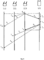
- Fig. 4 shows a signalling scheme depicting an example of a signalling between the primary node 110, the secondary nodes 111, 112 and the device 121 according to implementations described herein.
- the primary node 110 transmits the positioning data packet SA at a time TP0 to the device 121.
- the positioning data packet SA is received at the wireless device 121.
- the positioning data packet SA is also received by the secondary node 111 at time TSA1 and received by the secondary node 112 at time TSA2. Since the secondary node 111 and the secondary node 112 knows its own position and the position of the primary node 110 between which there is a known relative time difference, the secondary node 111 and the secondary node 112 may determine the transmitting time TP0 of the positioning data packet SA at the primary node 110 based on the reception times TSA1 and TSA2, respectively.
- the device 121 may process the positioning data packet during a processing time TK.
- the processing time TK in the device 121 may be designed to be stable and accurate enough in order for the nodes in the wireless communications network 110 to assumed it to be fixed and constant.
- the processing time TK in the device 121 may be determined with an accuracy of below one or a few nano-second (ns).
- the wireless device 121 may transmit a request response SB back to the primary node 110.
- the request response SB is received by the primary node 110 at time TP1.
- the request response SB is also received by the secondary node 111 at time TSB1 and received by the secondary node 112 at time TSB2. Since the secondary node 111 and the secondary node 112 has determined the transmitting time TP0 of the positioning data packet SA at the primary node 110, the secondary node 111 and the secondary node 112 may, for example, determine an RTT of the positioning data packet-request response exchange, albeit originating from the primary node 110.
- Transmission times such as, ToF and TDoA, may also be determined by the secondary node 111 and the secondary node 112 based on the positioning data packet-request response exchange between the primary node 110 and the device 121. This determined timing information may then be used in determining the distance between the device 121 and each of the primary node 110 and the secondary node 111, 112, which subsequently may be used in determining the position of the device 121 in the wireless communications network 100.
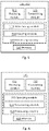
- the secondary node 111, 112 may comprise the following arrangement depicted in Fig. 5.
- Fig. 5 shows a schematic block diagram of embodiments of the secondary node 111, 112.
- the secondary node 111, 112 may comprise a processing circuitry 510, a memory 520 and at least one antenna (not shown).
- the secondary node 111, 112 may also comprise a receiving module 511 and a transmitting module 512.
- the receiving module 511 and the transmitting module 512 may comprise Radio Frequency, RF, circuitry and baseband processing circuitry.
- the receiving module 511 and the transmitting module 512 may also form part of a transceiver.
- the processor 510 may also be referred to as processing module, processing unit or processing circuitry.
- the receiving module 511 may also be referred to as a receiver or receiving unit, and the transmitting module 512 may also be referred to as transmitter or transmitting unit.
- some or all of the functionality described above as being performed by the secondary node 111, 112 may be provided by the processing circuitry 510 executing instructions stored on a computer-readable medium, such as, the memory 520 shown in Fig. 5 .
- Embodiments of the secondary node 111, 112 may comprise additional components, such as, the determining module 513 and the enabling module 514, responsible for providing its functionality necessary to support the embodiments described herein.
- the secondary node 111, 112 or processing circuitry 510 is configured to, or may comprise the receiving module 511 configured to, receive a positioning data packet from a primary node 110 to the device 121. Also, the secondary node 111, 112 or processing circuitry 510 is configured to, or may comprise the determining module 513 configured to, determine the transmitting time of the positioning data packet based on the reception time of the positioning data packet in the secondary node 111, 112 and the position of the primary node 110 and the secondary node 111, 112. Further, the secondary node 111, 112 or processing circuitry 510 is configured to, or may comprise the receiving module 511 configured to, receive a request response from the device 121 to the primary node 110. Furthermore, the secondary node 111, 112 or processing circuitry 510 is configured to, or may comprise the enabling module 514 configured to, enable positioning of the device 121 based on the determined transmitting time of the positioning data packet and the reception time of the received request response.
- the secondary node 111, 112 or processing circuitry 510 may be configured to, or may comprise the determining module 513 being configured to, determine the transmitting time based on the position of the primary node 110 and the secondary node 111, 112, wherein the position of the primary node 110 and the secondary node 111, 112 are at least temporarily stationary and determined in the secondary node 111, 112. Also, in some embodiments, the secondary node 111, 112 or processing circuitry 510 may be configured to, or may comprise the determining module 513 being configured to, determine a transmission time between the secondary node 111, 112 and the device 121 based on the determined transmitting time of the positioning data packet and the received reception time of the request response.
- the secondary node 111, 112 or processing circuitry 510 may be configured to, or may comprise the transmitting module 512 configured to, transmit the determined transmitting time of the positioning data packet, the reception time of the received request response, and/or the determined transmission time to another node in the wireless communications network 100.
- the secondary node 111, 112 or processing circuitry 510 may be configured to, or may comprise the receiving module 511 configured to, receive at least one transmission time between the device 121 and another node in the wireless communications network 100.
- the secondary node 111, 112 or processing circuitry 510 may be configured to, or may comprise the determining module 513 configured to, determine the position of the device 121 based on at least the received at least one transmission time and one or more of the determined transmitting time of the positioning data packet, the reception time of the received request response, and/or the determined transmission time.
- the embodiments for enabling positioning of a device 121 in a wireless communications network 100 are implemented also through one or more processors, such as, e.g. the processor 510 in the secondary node 111, 112 depicted in Figure 5 , together with computer program code for performing the functions and actions of the embodiments herein.
- the program code mentioned above is also provided as a computer program product, in the form of a data carrier carrying computer program code or code means for performing the embodiments herein when being loaded into the processor 510 in the secondary node 111, 112.
- the computer program code may e.g. be provided as pure program code in the secondary node 111, 112 or on a server and downloaded to the secondary node 111, 112.
- the carrier may be one of an electronic signal, optical signal, radio signal, or computer-readable storage medium, such as, e.g. electronic memories like a RAM, a ROM, a Flash memory, a magnetic tape, a CD-ROM, a DVD, a Blu-ray disc, etc.
- some embodiments may comprise a computer program product, comprising instructions which, when executed on at least one processor, e.g. the processor 510, cause the at least one processor to carry out the method for enabling positioning of a device 121 in a wireless communications network 100.
- the secondary node 111, 112 may further comprise the memory 520, which may be referred to or comprise one or more memory modules or units.
- the memory 520 may be arranged to be used to store executable instructions and data to perform the methods described herein when being executed in or by the processor 510 of the secondary node 111, 112.
- the processor 510 and the memory 520 described above may refer to a combination of analog and digital circuits, and/or one or more processors configured with software and/or firmware, e.g. stored in the memory 520, that when executed by the one or more processors, such as, the processor 510, cause the one or more processors to perform the method as described above.
- the processor 510 and the memory 520 may also be referred to as processing means.
- One or more of these processors, as well as the other digital hardware, may be included in a single application-specific integrated circuit (ASIC), or several processors and various digital hardware may be distributed among several separate components, whether individually packaged or assembled into a system-on-a-chip (SoC).
- ASIC application-specific integrated circuit
- SoC system-on-a-chip
- the central node 101 may comprise the following arrangement depicted in Fig. 6.
- Fig. 6 shows a schematic block diagram of embodiments of the central node 101.
- the central node 101 may comprise a processing circuitry 610 and a memory 620.
- the central node 101 may further comprise a receiving module 611 and a transmitting module 612.
- the receiving module 611 and the transmitting module 612 may also form part of a transceiver.
- the processor 610 may also be referred to as processing module, processing unit or processing circuitry.
- the receiving module 611 may also be referred to as a receiver or receiving unit, and the transmitting module 612 may also be referred to as transmitter or transmitting unit.
- the central node 101 is configured to communicate with two or more nodes 110, 111, 112 in the wireless communications network 100, e.g. via the receiving module 611 and the transmitting module 612.
- some or all of the functionality described above as being performed by the secondary node 111, 112 may be provided by the processing circuitry 610 executing instructions stored on a computer-readable medium, such as, the memory 620 shown in Fig. 6 .
- Implementations, of the central node 101 may comprise additional components, such as, the selecting module 613 and the determining module 614, responsible for providing its functionality necessary to support the embodiments described herein.
- the central node 101 or processing circuitry 610 is configured to, or may comprise the selecting module 613 configured to, select a primary node of the two or more nodes 110, 111, 112 for transmitting one or more positioning data packets to the device 121. Also, the central node 101 or processing circuitry 610 is configured to, or may comprise the receiving module 611 configured to, receive two or more transmission times between the two or more nodes 110, 111, 112 and the device 121 based on the one or more positioning data packets transmitted by the selected primary node 110. Further, the central node 101 or processing circuitry 610 is configured to, or may comprise the determining module 614 configured to, determine the position of the device 121 based on at least the received two or more transmission times.
- the central node 101 or processing circuitry 610 may be configured to, or may comprise the selecting module 613 configured to, select the primary node based on the total time that each of the two or more nodes 110, 111, 112 has spent on transmitting positioning data packets to the device 121.
- the central node 101 or processing circuitry 610 may be configured to, or may comprise the selecting module 613 configured to, select another one of the two or more nodes 110, 111, 112 as the primary node for transmitting one or more positioning data packets to the device 121 in case the total time that a selected primary node 110 has spent on transmitting positioning data packets to the device 121 is passed a first determined threshold. In this case, according to some implementations, the total time that said another one of the two or more nodes 110, 111, 112 has spent on transmitting positioning data packets to the device 121 is passed a second determined threshold.
- the implementations for positioning a device 121 in a wireless communications network 100 may be implemented through one or more processors, such as, e.g. the processor 610 in the central node 101 depicted in Figure 6 , together with computer program code for performing the functions and actions of the implementations herein.
- the program code mentioned above is also be provided as a computer program product, in the form of a data carrier carrying computer program code or code means for performing the embodiments herein when being loaded into the processor 610 in the central node 101.
- the computer program code may e.g. be provided as pure program code in the central node 101 or on a server and downloaded to the central node 101.
- the carrier may be one of an electronic signal, optical signal, radio signal, or computer-readable storage medium, such as, e.g.
- some embodiments may comprise a computer program product, comprising instructions which, when executed on at least one processor, e.g. the processor 810, cause the at least one processor to carry out the method for positioning a device 121 in a wireless communications network 100.
- the network node 110 may further comprise the memory 620, which may be referred to or comprise one or more memory modules or units.
- the memory 620 may be arranged to be used to store executable instructions and data to perform the methods described herein when being executed in or by the processor 610 of the central node 101.
- the processor 610 and the memory 620 described above may refer to a combination of analog and digital circuits, and/or one or more processors configured with software and/or firmware, e.g. stored in the memory 620, that when executed by the one or more processors, such as, the processor 610, cause the one or more processors to perform the method as described above.
- the processor 610 and the memory 620 may also be referred to as processing means.
- processors may be included in a single application-specific integrated circuit (ASIC), or several processors and various digital hardware may be distributed among several separate components, whether individually packaged or assembled into a system-on-a-chip (SoC).
- ASIC application-specific integrated circuit
- SoC system-on-a-chip
- the common abbreviation "e.g.” which derives from the Latin phrase “exempli gratia,” may be used to introduce or specify a general example or examples of a previously mentioned item, and is not intended to be limiting of such item. If used herein, the common abbreviation “i.e.”, which derives from the Latin phrase “id est,” may be used to specify a particular item from a more general recitation.
- the common abbreviation “etc.”, which derives from the Latin expression “et cetera” meaning “and other things” or “and so on” may have been used herein to indicate that further features, similar to the ones that have just been enumerated, exist.
Landscapes
- Engineering & Computer Science (AREA)
- Radar, Positioning & Navigation (AREA)
- Remote Sensing (AREA)
- Physics & Mathematics (AREA)
- General Physics & Mathematics (AREA)
- Computer Networks & Wireless Communication (AREA)
- Signal Processing (AREA)
- Mobile Radio Communication Systems (AREA)
- Position Fixing By Use Of Radio Waves (AREA)
Description
- Embodiments herein relate to positioning in wireless communications network. In particular, embodiments herein relate to a secondary node and method therein for enabling positioning of a device in a wireless communications network. Also, embodiments herein relate to a central node and method therein for positioning a device in a wireless communications network. Further, embodiments also relate to a corresponding system and products.
- Positioning of a device, such as, e.g. wireless device, mobile device, or user equipment, in a wireless communications network, such as, e.g. networks under the 802.11x Wi-Fi standard, Bluetooth standard, 802.15x Zigbee standard, or any other suitable wireless communications network, may conventionally be based on so-called Round Trip Time, RTT, measurements. The RTT between a node and a device in a wireless communications system may be measured as the time from transmission of a request signal from the node to the device up until a response signal from the device is received back at the node. The RTT may then be used to determine a distance between the node and the device. Unfortunately, the RTT will also comprise an unknown processing time/time delay in the device after first receiving the request signal from a node and before a response signal is sent back to the node. This processing time is usually non-deterministic and may vary significantly between different devices, for example, due to the current work load of the processor therein. This will lead poor precision in the determination of a distance between the node and the device.
- Another way of determining a distance between a node and a device in a wireless communications network is to exclude the processing time in the device by measuring only the one-way Time of Flight, ToF, between the node and the device. However, this requires that the same time base is used at both the node and the device, and achieving a mutual time base in a node and a device require some form of clock synchronization between the node and the device.
- Furthermore, no matter if RTT or one-way ToF is used for determining the distance between a node and a device for the purpose of obtaining the position of a device in a wireless communications network, there may also be restrictions in the wireless communications network that limits the number of transmissions, and/or on air time, that the nodes in the wireless communications network may perform. It follows that the number and/or length of possible request-response signal exchanges between a node and a device in the wireless communications network may be limited, or that the time or clock synchronization between a node and a device in the wireless communications network is not possible. Document
US 2009/149198 discloses a position tracking system has a target node and several reference nodes having position information. An arbitrary reference node among the reference nodes and the target node utilizes distance measurement message to measure TOA and to transmit TOA to position determination device. The other reference nodes adjacent to arbitrary reference node and the target node listen to distance measurement message to measure another TOA and transmit TOA to the position determination device. - It is an object of embodiments herein to improve the positioning of a device in a wireless communications network.
- The invention is embodied in the independent claims 1, 4, 7, 11, 13-15. Optional embodiments are reflected in the dependent claims.
- By having a secondary node in a wireless communications network intercepting positioning data packets from a primary node to a device and having information about the currently fixed position of both the primary and secondary node, the secondary node is capable of determining the transmitting time of the positioning data packet from the primary node by subtracting the known time difference between the currently fixed positions of the primary and second node. This essentially achieves a synchronization of the primary and secondary node, at least in relative time, without having to conduct any actual time synchronization in the wireless communications network. Then, by receiving the request response from the device, the secondary node may enable the positioning of the device in the wireless communications network based on the determined transmitting time of the positioning data packet and the reception time of the request response. This may be performed either by forwarding these timing parameters, or determined timing information related thereto, to a central node for positioning of the device or by using these parameters itself in the secondary node in positioning of the device. This advantageously also reduces the number of transmissions, i.e. positioning data packet-request response exchanges, required to be transmitted in the wireless communications network since the secondary node may utilize the transmissions of the primary node. This advantage also increases with the number of secondary nodes in the wireless communications network. Hence, the signalling required when positioning of a device in a wireless communications network is reduced. Thus, positioning of a device in a wireless communications network is improved. The term request response as used herein is intended as a response to the positioning data packet sent to the device and the request response is transmitted from the device.
- Features and advantages of the embodiments will become readily apparent to those skilled in the art by the following detailed description of exemplary embodiments thereof with reference to the accompanying drawings, wherein:
- Figure 1
- is a schematic block diagram illustrating a device, a central node, and secondary nodes in a wireless communications network,
- Figure 2
- is a flowchart depicting a method in a secondary node
- Figure 3
- is a flowchart depicting a method in a central node
- Figure 4
- is a signalling scheme depicting a secondary node
- Figure 5
- is a schematic block diagram depicting a secondary node
- Figure 6
- is a schematic block diagram depicting a central node
- The figures are schematic and simplified for clarity, and they merely show details which are essential to the understanding of the embodiments presented herein, while other details have been left out. Throughout, the same reference numerals are used for identical or corresponding parts or steps.
-
Fig. 1 shows an example of awireless communications network 100 in which embodiments herein may be implemented. It should be noted that thewireless communications network 100 may be a separate standalone wireless communications network dedicated to the positioning of a device, but may also be implemented using parts of a conventional wireless communications network or radio communication system, such as, New Radio (NR), Long Term Evolution (LTE), a LTE-Advanced, Wideband Code-Division Multiple Access (WCDMA), Global System for Mobile communications/Enhanced Data rate for GSM Evolution (GSM/EDGE), Worldwide Interoperability for Microwave Access (WiMax), Ultra Mobile Broadband (UMB), GSM network, or other cellular network, or system or radio networks, such as, a future 5G wireless communication system. - In the example shown in
Fig. 1 , thewireless communications network 100 comprises acentral node 101 that may be connected to and/or form a part of a cloud-basedcommunication infrastructure 102 accessible via the Internet or similar communication networks. It should be noted that the cloud-basedcommunication infrastructure 102 is merely one example of how the core part of thewireless communications network 100 may be implemented. Other solutions may include, for example, LANs/WANs, Local Area Networks or Wide Area Networks accessible via the Internet or similar communication networks. Thecentral node 101, for example, a server or similar dedicated data processing unit, may be configured to communicate with one or more nodes or network nodes in thewireless communications network 100, such as, for example, theprimary node 110 andsecondary nodes Fig. 1 . Since thecentral node 101 may be used to determine the position of a device in thewireless communications network 100, thecentral node 101 may also be referred to as, for example, a positioning node, a positioning server or a positioning unit. - The
primary node 110 andsecondary nodes device 121 within an Industrial, Scientific and Medical (ISM) radio band and/or on a frequency between 300 MHz to 1000 MHz. Thus, theprimary node 110 andsecondary nodes device 121. Correspondingly, thedevice 121 may be a wireless device configured to communicate with theprimary node 110 andsecondary nodes device 121 is configured for wireless signalling with theprimary node 110 andsecondary nodes primary node 110 andsecondary nodes device 121 may be dedicated solely for the purpose of positioning thedevice 121 within thewireless communications network 100. - Furthermore, although embodiments below are described with reference to the scenario of
Figure 1 , this scenario should not be construed as limiting to the embodiments herein, but merely as an example made for illustrative purposes. For example, the number of secondary nodes in thewireless communications network 100 may be any suitable number of nodes. - Example of a method performed by a
secondary node device 121 in awireless communications network 100, will now be described with reference to the flowchart depicted inFigure 2. Figure 2 illustrates an example of actions or operations which may be taken by thesecondary node - The
secondary node primary node 110 to thedevice 121. This means thesecondary node primary node 110 to thedevice 121 in thewireless communications network 100. The positioning data packet may be a test signal or data packet, e.g. a so-called "ping" signal, carrying no data payload, a data payload, or a reduced or minimized data payload. In one embodiment the data packet may comprise only enough information for thedevice 121 to respond with a request response. In one embodiment the data packet comprises enough information to identify theprimary node 110 to thedevice 121. The positioning data packet may also, for example, be a Request-To-Send (RTS) message. - In some implementations, the reception of the positioning data packet may be performed within an ISM radio band and/or on a frequency between 300 MHz to 1000 MHz. This means that the
secondary node - In some implementations, the reception of the positioning data packet may be performed within an ISM radio band and/or on a frequency between 1000 MHz to 10 000 MHz.
- After receiving the positioning data packet in
Action 201, thesecondary node secondary node primary node 110 and thesecondary node secondary node primary node 110 in order to determine when the positioning data packet was transmitted from theprimary node 110 to thedevice 121. Since the propagation speed of radio waves and the positions of theprimary node 110 and thesecondary node primary node 110 and thesecondary node secondary node primary node 110, i.e. the transmitting time of the positioning data packet. - According to some implementations, the position of the
primary node 110 and thesecondary node secondary node primary node 110 and thesecondary node primary node 110 and thesecondary node primary node 110 and thesecondary node primary node 110 and thesecondary node secondary node - The positions of the
primary node 110 and the secondary node(s) 111, 112 may in one implementation be determined via positioning using radio technology as described herein. In another embodiment the positions for theprimary node 110 and secondary node(s) 111, 112 might be determined via for example GPS. In yet another implementation the positions might be fixed positions known to the nodes, either entered manually or known via for example acentral node 101. - The
secondary node device 121 to theprimary node 110. This means thesecondary node device 121 to theprimary node 110 in thewireless communications network 100 in response to the earlier intercepted positioning data packet. Similar to the positioning data packet, the request response may also be a test signal or data packet carrying no data payload or at least a reduced or minimized data payload, but enough information to identify thedevice 121 to theprimary node 110. The request response may also be referred to as a "pong" signal, since it is transmitted in response to the positioning data packet, i.e. a "ping" signal. The request response may also, for example, be a Clear-To-Send (CTS) message. In some embodiments, the reception of the request response may be performed within an ISM radio band and/or on a frequency between 300 MHz to 1000 MHz. In some embodiments, the reception of the request response may be performed within an ISM radio band and/or on a frequency between 1000 MHz to 10 000 MHz. - After receiving the request response in
Action 203, thesecondary node device 121 based on the determined transmitting time of the positioning data packet and the reception time of the received request response. In other words, thesecondary node primary node 110 and thedevice 121, register and obtain timing information that may be used to accurately determine the position of thedevice 121. This advantageously provides a way of using a single positioning data packet-request response exchange between aprimary node 110 and adevice 121, in order to effectively achieve similar result for all nodes in thewireless communications network 100 as if all of thenodes device 121 themselves. - In some implementations, the
secondary node secondary node device 121 based on the determined transmitting time of the positioning data packet and the received reception time of the request response. This means that thesecondary node primary node 110 and thedevice 121. It should be noted that the RTT in this case originates from theprimary node 110 and that it per definition might not be considered as RTT. I.e. the distance is measured from theprimary node 110, via thedevice 121 to thesecondary node - In some embodiments, the
secondary node wireless communications network 100. This means that thesecondary node primary node 110 and thedevice 121 to another node in thewireless communications network 100, such as, e.g. thecentral node 101. This registered or obtained timing information may then be used by another node in order to determine the position of thedevice 121 in thewireless communications network 100, for example, by determining the distance between thesecondary node device 121. - Optionally, in some embodiments, the
secondary node device 121 and another node in thewireless communications network 100. In this case, thesecondary node device 121 based on at least the received at least one transmission time and one or more of the determined transmitting time of the positioning data packet, the reception time of the received request response, and/or the determined transmission time. This means, for example, that instead of transmitting the registered or obtained timing information associated with the intercepted signals between theprimary node 110 and thedevice 121 to e.g. thecentral node 101, thesecondary node wireless communications network 100, such as, for example, theprimary node 110 or further possible secondary nodes in thewireless communications network 100. This enables thesecondary node device 121 in thewireless communications network 100, for example, by determining the distance between thedevice 121 and more than one node in the wireless communications network, e.g. theprimary node 110 and thesecondary nodes device 121 in thewireless communications network 100, the position of thedevice 121 may be transmitted to other nodes in thewireless communications network 100. This enables data processing or calculations involved in determining the position of thedevice 121 in thewireless communications network 100 to be distributed among the nodes in thewireless communications network 100. - In this case, according to some implementations, the
secondary node device 121 further based on that the processing time in thedevice 121 from the reception of the positioning data packet to the transmitting of the request response is set and determined in thesecondary node device 121 may be assumed to be fixed and constant in thesecondary node 111, 112.The processing time of thedevice 121 may, for example, be predefined, manually inputted or downloaded in thesecondary node 111, 122. - It should also be noted that the positioning data packet-request response exchange, i.e. the transmissions of a positioning data packet and the corresponding request response, between the
primary node 110 and thedevice 121 may, for example, be performed between 1-250 times. Consequently, thesecondary nodes primary node 110 and thedevice 121 may, for example, be determined depending on the desired accuracy of the determination of the position of thedevice 121. For example, a distance between thedevice 121 and each of theprimary node 110 and thesecondary node device 121 in thewireless communications network 100. - Implementations, of a method performed by a
central node 101 for positioning adevice 121 in awireless communications network 100, will now be described with reference to the flowchart depicted inFigure 3. Figure 3 illustrates an example of actions or operations which may be taken by thecentral node 101. Thecentral node 101 being configured to communicate with two ormore nodes wireless communications network 100. The method may comprise the following actions. - The
central node 101 selects a primary node of the two ormore nodes device 121. This means, for example, that any of two ormore nodes central node 101. Advantageously, thecontrol node 101 may thus select the most suitable of the two ormore nodes more nodes nodes more nodes more nodes node device 121 is selected as the primary node. In some embodiments thenode node - In some implementations, the
central node 101 may select a primary node based on the total time that each of the two ormore nodes device 121. This may be advantageously, for example, when there are regulatory requirements on the total air time, i.e. total time of transmissions occupying the radio frequency channel, that a node may be required to follow, since it allows thecentral node 101 to compare the accumulated air time of each of the two ormore nodes more nodes more nodes central node 101 may select another one of the two ormore nodes device 121 in case the total time that a selectedprimary node 110 has spent on transmitting positioning data packets to thedevice 121 is passed a first determined threshold. Here, the total time that the another one of the two ormore nodes device 121 is passed a second determined threshold. For example, in case there is a regulatory requirement that limits the air time of a node to e.g. 100 seconds, then thecentral node 101 may switch primary node from a currently selected primary node, e.g. theprimary node 110, to another one of the two or more nodes, e.g. one of thesecondary nodes central node 101. - After the selection in
Action 301, thecentral node 101 receives timing information from the two ormore nodes primary node 110 and a request response from thedevice 121 to the positioning data packet transmitted by the selectedprimary node 110. Thus, thecentral node 101 may obtain and gather the timing information from each of the two ormore nodes wireless communications network 100 based on a single positioning data packet-request response exchange between theprimary node 110 and thedevice 121. In some embodiments, the timing information may comprise determined transmitting times of the positioning data packet, reception times of the received request response, and/or determined transmission times in the two ormore nodes - After the reception in
Action 302, thecentral node 101 may determine the position of thedevice 121 based on the received timing information. This means that thecentral node 101 use the obtained and gathered timing information from each of the two ormore nodes wireless communications network 100 in order to determine the position of thedevice 121 in thewireless communications network 100. - According to some implementations, the
central node 101 may determine the position of thedevice 121 further based on that the processing time in thedevice 121 from the reception of the positioning data packet to the transmitting of the request response is set and determined in thecentral node 101. This means, for example, that the processing time in thedevice 121 may be assumed to be stable and constant in thecentral node 101. The processing time of thedevice 121 may, for example, be predefined, manually inputted or downloaded in thecentral node 101. -
Fig. 4 shows a signalling scheme depicting an example of a signalling between theprimary node 110, thesecondary nodes device 121 according to implementations described herein. - First, the
primary node 110 transmits the positioning data packet SA at a time TP0 to thedevice 121. After a transmission time TP, the positioning data packet SA is received at thewireless device 121. Correspondingly, the positioning data packet SA is also received by thesecondary node 111 at time TSA1 and received by thesecondary node 112 at time TSA2. Since thesecondary node 111 and thesecondary node 112 knows its own position and the position of theprimary node 110 between which there is a known relative time difference, thesecondary node 111 and thesecondary node 112 may determine the transmitting time TP0 of the positioning data packet SA at theprimary node 110 based on the reception times TSA1 and TSA2, respectively. - After receiving the positioning data packet, the
device 121 may process the positioning data packet during a processing time TK. The processing time TK in thedevice 121 may be designed to be stable and accurate enough in order for the nodes in thewireless communications network 110 to assumed it to be fixed and constant. For example, the processing time TK in thedevice 121 may be determined with an accuracy of below one or a few nano-second (ns). - After the processing time TK, the
wireless device 121 may transmit a request response SB back to theprimary node 110. After the transmission time TP, the request response SB is received by theprimary node 110 at time TP1. Correspondingly, the request response SB is also received by thesecondary node 111 at time TSB1 and received by thesecondary node 112 at time TSB2. Since thesecondary node 111 and thesecondary node 112 has determined the transmitting time TP0 of the positioning data packet SA at theprimary node 110, thesecondary node 111 and thesecondary node 112 may, for example, determine an RTT of the positioning data packet-request response exchange, albeit originating from theprimary node 110. Other transmission times, such as, ToF and TDoA, may also be determined by thesecondary node 111 and thesecondary node 112 based on the positioning data packet-request response exchange between theprimary node 110 and thedevice 121. This determined timing information may then be used in determining the distance between thedevice 121 and each of theprimary node 110 and thesecondary node device 121 in thewireless communications network 100. - To perform the method actions for enabling positioning of a
device 121 in awireless communications network 100, thesecondary node Fig. 5. Fig. 5 shows a schematic block diagram of embodiments of thesecondary node - The
secondary node processing circuitry 510, amemory 520 and at least one antenna (not shown). Thesecondary node receiving module 511 and atransmitting module 512. The receivingmodule 511 and thetransmitting module 512 may comprise Radio Frequency, RF, circuitry and baseband processing circuitry. The receivingmodule 511 and thetransmitting module 512 may also form part of a transceiver. Theprocessor 510 may also be referred to as processing module, processing unit or processing circuitry. The receivingmodule 511 may also be referred to as a receiver or receiving unit, and thetransmitting module 512 may also be referred to as transmitter or transmitting unit. In particular embodiments, some or all of the functionality described above as being performed by thesecondary node processing circuitry 510 executing instructions stored on a computer-readable medium, such as, thememory 520 shown inFig. 5 . Embodiments of thesecondary node module 513 and the enablingmodule 514, responsible for providing its functionality necessary to support the embodiments described herein. - The
secondary node processing circuitry 510 is configured to, or may comprise the receivingmodule 511 configured to, receive a positioning data packet from aprimary node 110 to thedevice 121. Also, thesecondary node processing circuitry 510 is configured to, or may comprise the determiningmodule 513 configured to, determine the transmitting time of the positioning data packet based on the reception time of the positioning data packet in thesecondary node primary node 110 and thesecondary node secondary node processing circuitry 510 is configured to, or may comprise the receivingmodule 511 configured to, receive a request response from thedevice 121 to theprimary node 110. Furthermore, thesecondary node processing circuitry 510 is configured to, or may comprise the enablingmodule 514 configured to, enable positioning of thedevice 121 based on the determined transmitting time of the positioning data packet and the reception time of the received request response. - In some implementations, the
secondary node processing circuitry 510 may be configured to, or may comprise the determiningmodule 513 being configured to, determine the transmitting time based on the position of theprimary node 110 and thesecondary node primary node 110 and thesecondary node secondary node secondary node processing circuitry 510 may be configured to, or may comprise the determiningmodule 513 being configured to, determine a transmission time between thesecondary node device 121 based on the determined transmitting time of the positioning data packet and the received reception time of the request response. In some embodiments, thesecondary node processing circuitry 510 may be configured to, or may comprise the transmittingmodule 512 configured to, transmit the determined transmitting time of the positioning data packet, the reception time of the received request response, and/or the determined transmission time to another node in thewireless communications network 100. - Further, in some implementations, the
secondary node processing circuitry 510 may be configured to, or may comprise the receivingmodule 511 configured to, receive at least one transmission time between thedevice 121 and another node in thewireless communications network 100. In this case, thesecondary node processing circuitry 510 may be configured to, or may comprise the determiningmodule 513 configured to, determine the position of thedevice 121 based on at least the received at least one transmission time and one or more of the determined transmitting time of the positioning data packet, the reception time of the received request response, and/or the determined transmission time. - The embodiments for enabling positioning of a
device 121 in awireless communications network 100 are implemented also through one or more processors, such as, e.g. theprocessor 510 in thesecondary node Figure 5 , together with computer program code for performing the functions and actions of the embodiments herein. The program code mentioned above is also provided as a computer program product, in the form of a data carrier carrying computer program code or code means for performing the embodiments herein when being loaded into theprocessor 510 in thesecondary node secondary node secondary node processor 510, cause the at least one processor to carry out the method for enabling positioning of adevice 121 in awireless communications network 100. - The
secondary node memory 520, which may be referred to or comprise one or more memory modules or units. Thememory 520 may be arranged to be used to store executable instructions and data to perform the methods described herein when being executed in or by theprocessor 510 of thesecondary node processor 510 and thememory 520 described above may refer to a combination of analog and digital circuits, and/or one or more processors configured with software and/or firmware, e.g. stored in thememory 520, that when executed by the one or more processors, such as, theprocessor 510, cause the one or more processors to perform the method as described above. Theprocessor 510 and thememory 520 may also be referred to as processing means. One or more of these processors, as well as the other digital hardware, may be included in a single application-specific integrated circuit (ASIC), or several processors and various digital hardware may be distributed among several separate components, whether individually packaged or assembled into a system-on-a-chip (SoC). - To perform the method actions for positioning a
device 121 in awireless communications network 100, thecentral node 101 may comprise the following arrangement depicted inFig. 6. Fig. 6 shows a schematic block diagram of embodiments of thecentral node 101. - The
central node 101 may comprise aprocessing circuitry 610 and amemory 620. Thecentral node 101 may further comprise areceiving module 611 and atransmitting module 612. The receivingmodule 611 and thetransmitting module 612 may also form part of a transceiver. Theprocessor 610 may also be referred to as processing module, processing unit or processing circuitry. The receivingmodule 611 may also be referred to as a receiver or receiving unit, and thetransmitting module 612 may also be referred to as transmitter or transmitting unit. Thecentral node 101 is configured to communicate with two ormore nodes wireless communications network 100, e.g. via thereceiving module 611 and thetransmitting module 612. In particular embodiments, some or all of the functionality described above as being performed by thesecondary node processing circuitry 610 executing instructions stored on a computer-readable medium, such as, thememory 620 shown inFig. 6 . Implementations, of thecentral node 101 may comprise additional components, such as, the selectingmodule 613 and the determiningmodule 614, responsible for providing its functionality necessary to support the embodiments described herein. - The
central node 101 orprocessing circuitry 610 is configured to, or may comprise the selectingmodule 613 configured to, select a primary node of the two ormore nodes device 121. Also, thecentral node 101 orprocessing circuitry 610 is configured to, or may comprise the receivingmodule 611 configured to, receive two or more transmission times between the two ormore nodes device 121 based on the one or more positioning data packets transmitted by the selectedprimary node 110. Further, thecentral node 101 orprocessing circuitry 610 is configured to, or may comprise the determiningmodule 614 configured to, determine the position of thedevice 121 based on at least the received two or more transmission times. - In some implementations, the
central node 101 orprocessing circuitry 610 may be configured to, or may comprise the selectingmodule 613 configured to, select the primary node based on the total time that each of the two ormore nodes device 121. In some implementations, thecentral node 101 orprocessing circuitry 610 may be configured to, or may comprise the selectingmodule 613 configured to, select another one of the two ormore nodes device 121 in case the total time that a selectedprimary node 110 has spent on transmitting positioning data packets to thedevice 121 is passed a first determined threshold. In this case, according to some implementations, the total time that said another one of the two ormore nodes device 121 is passed a second determined threshold. - The implementations for positioning a
device 121 in awireless communications network 100 may be implemented through one or more processors, such as, e.g. theprocessor 610 in thecentral node 101 depicted inFigure 6 , together with computer program code for performing the functions and actions of the implementations herein. The program code mentioned above is also be provided as a computer program product, in the form of a data carrier carrying computer program code or code means for performing the embodiments herein when being loaded into theprocessor 610 in thecentral node 101. The computer program code may e.g. be provided as pure program code in thecentral node 101 or on a server and downloaded to thecentral node 101. The carrier may be one of an electronic signal, optical signal, radio signal, or computer-readable storage medium, such as, e.g. electronic memories like a RAM, a ROM, a Flash memory, a magnetic tape, a CD-ROM, a DVD, a Blu-ray disc, etc. From the above it may be seen that some embodiments may comprise a computer program product, comprising instructions which, when executed on at least one processor, e.g. the processor 810, cause the at least one processor to carry out the method for positioning adevice 121 in awireless communications network 100. - The
network node 110 may further comprise thememory 620, which may be referred to or comprise one or more memory modules or units. Thememory 620 may be arranged to be used to store executable instructions and data to perform the methods described herein when being executed in or by theprocessor 610 of thecentral node 101. Those skilled in the art will also appreciate that theprocessor 610 and thememory 620 described above may refer to a combination of analog and digital circuits, and/or one or more processors configured with software and/or firmware, e.g. stored in thememory 620, that when executed by the one or more processors, such as, theprocessor 610, cause the one or more processors to perform the method as described above. Theprocessor 610 and thememory 620 may also be referred to as processing means. One or more of these processors, as well as the other digital hardware, may be included in a single application-specific integrated circuit (ASIC), or several processors and various digital hardware may be distributed among several separate components, whether individually packaged or assembled into a system-on-a-chip (SoC). - The terminology used in the detailed description of the particular embodiments illustrated in the accompanying drawings is not intended to be limiting of the described
wireless device 121,network node 110 and methods therein which instead should be construed in view of the enclosed claims. - As used herein, the term "and/or" comprises any and all combinations of one or more of the associated listed items.
- Further, as used herein, the common abbreviation "e.g.", which derives from the Latin phrase "exempli gratia," may be used to introduce or specify a general example or examples of a previously mentioned item, and is not intended to be limiting of such item. If used herein, the common abbreviation "i.e.", which derives from the Latin phrase "id est," may be used to specify a particular item from a more general recitation. The common abbreviation "etc.", which derives from the Latin expression "et cetera" meaning "and other things" or "and so on" may have been used herein to indicate that further features, similar to the ones that have just been enumerated, exist.
- As used herein, the singular forms "a", "an" and "the" are intended to comprise also the plural forms as well, unless expressly stated otherwise. It will be further understood that the terms "includes," "comprises," "including" and/or "comprising," when used in this specification, specify the presence of stated features, actions, integers, steps, operations, elements, and/or components, but do not preclude the presence or addition of one or more other features, actions, integers, steps, operations, elements, components, and/or groups thereof.
- Unless otherwise defined, all terms comprising technical and scientific terms used herein have the same meaning as commonly understood by one of ordinary skill in the art to which the described embodiments belongs. It will be further understood that terms, such as those defined in commonly used dictionaries, should be interpreted as having a meaning that is consistent with their meaning in the context of the relevant art and will not be interpreted in an idealized or overly formal sense unless expressly so defined herein.
Claims (15)
- A method performed by a secondary node (111, 112) for enabling positioning of a device (121) in a wireless communications network (100), the method comprisingreceiving (201) a positioning data packet transmitted from a primary node (110) to the device (121);determining (202) the transmitting time of the positioning data packet based on the reception time of the positioning data packet in the secondary node (111, 112) and the position of the primary node (110) and the secondary node (111, 112);receiving (203) a request response transmitted from the device (121) to the primary node (110); anddetermining (204) the position of the device (121) based on the determined transmitting time of the positioning data packet, the reception time of the received request response and the known position of the secondary node (111, 112) and the primary node (110).
- The method according to claim 1, wherein the position of the primary node (110) and the secondary node (111, 112) are at least temporarily stationary.
- The method according to any one of claims 1 or 2, wherein determining (204) the position of the device (121) further comprises determining the distance between the device (121) and the primary node (110) and each of the secondary nodes (111,112) based on the determined transmitting time of the positioning data packet and the received reception time of the request response and determining the position of the device based on the determined distances.
- A secondary node (111, 112) for enabling positioning of a device (121) in a wireless communications network (100), the secondary node (111, 112) being configured to
receive a positioning data packet transmitted from a primary node (110) to the device (121), determine the transmitting time of the positioning data packet based on the reception time of the positioning data packet in the secondary node (111, 112) and the position of the primary node (110) and the secondary node (111, 112), receive a request response transmitted from the device (121) to the primary node (110), and determine the position of the device (121) based on the determined transmitting time of the positioning data packet, the reception time of the received request response and the known position of the secondary node (111, 112) and the primary node (110). - The secondary node (111, 112) according to claim 4, wherein the position of the primary node (110) and the secondary node (111, 112) are at least temporarily stationary and determined in the secondary node (111, 112).
- The secondary node (111, 112) according to any one of claims 4 or 5, further configured to determine the distance between the device (121) and the primary node (110) and each of the secondary nodes (111,112) based on the determined transmitting time of the positioning data packet and the received reception time of the request response, and to determine the position of the device based on the determined distances.
- A method performed by a central node (101) for positioning a device (121) in a wireless communications network (100), the central node (101) being configured to communicate with two or more nodes (110, 111, 112) in the wireless communications network (100), the method characterized byselecting (301) a primary node of the two or more nodes (110, 111, 112) to transmit a positioning data packet to the device (121), the remaining nodes of the two or more nodes (110, 111, 112) being secondary nodes;receiving (302) timing information from the two or more nodes (110, 111, 112), based on the positioning data packet transmitted by the selected primary node (110) and a request response from the device (121) to the positioning data packet transmitted by the selected primary node (110), anddetermining (303) the position of the device (121) based on the received timing information.
- The method according to claim 7, wherein the timing information may comprise determined transmitting times of the positioning data packet, reception times of the received request response, and/or determined transmission times in the two or more nodes (110, 111, 112).
- The method according to any one of claims 7 or 8, wherein the processing time in the device (121) from the reception of the positioning data packet to the transmission of the request response is set or determined in the central node (101).
- The method according to any of claims 7-9, wherein the selecting (301) is based on the total time that each of the two or more nodes (110, 111, 112) has spent on transmitting positioning data packets to the device (121).
- A central node (101) for positioning a device (121) in a wireless communications network (100), the central node (101) being configured to communicate with two or more nodes (110, 111, 112) in the wireless communications network (100), the central node (101) characterized in being configured to carry out the method of any of claims 7-9.
- The central node (101) according to claim 11, further configured to select the primary node based on the total time that each of the two or more nodes (110, 111, 112) has spent on transmitting positioning data packets to the device (121).
- A wireless communications network (100) comprising at least one secondary node (111, 112) according to any of claims 4-6, or comprising at least one secondary node (111, 112) according to any of claims 4-6 and a central node (101) according to any of claims 11-12.
- A computer program product, comprising instructions which, when executed on at least one processor (610, 620), cause the at least one processor (610, 620) to carry out the method according to any of claims 1-3 or 7-10.
- A carrier containing the computer program product according to claim 14, wherein the carrier is one of an electronic signal, optical signal, radio signal, or computer-readable storage medium.
Applications Claiming Priority (2)
| Application Number | Priority Date | Filing Date | Title |
|---|---|---|---|
| SE1750898A SE541867C2 (en) | 2017-07-07 | 2017-07-07 | A secondary node, a central node and methods therein for positioning of a device in a wireless communications network |
| PCT/SE2018/050680 WO2019009787A1 (en) | 2017-07-07 | 2018-06-25 | A secondary node, a central node and methods therein for positioning of a device in a wireless communications network |
Publications (2)
| Publication Number | Publication Date |
|---|---|
| EP3649810A1 EP3649810A1 (en) | 2020-05-13 |
| EP3649810B1 true EP3649810B1 (en) | 2022-10-26 |
Family
ID=62873571
Family Applications (1)
| Application Number | Title | Priority Date | Filing Date |
|---|---|---|---|
| EP18739658.5A Active EP3649810B1 (en) | 2017-07-07 | 2018-06-25 | A secondary node, a central node and methods therein for positioning of a device in a wireless communications network |
Country Status (8)
| Country | Link |
|---|---|
| US (1) | US11071082B2 (en) |
| EP (1) | EP3649810B1 (en) |
| JP (1) | JP7534851B2 (en) |
| KR (1) | KR102566507B1 (en) |
| BR (1) | BR112019028018A2 (en) |
| ES (1) | ES2934056T3 (en) |
| SE (1) | SE541867C2 (en) |
| WO (1) | WO2019009787A1 (en) |
Families Citing this family (3)
| Publication number | Priority date | Publication date | Assignee | Title |
|---|---|---|---|---|
| US11778583B2 (en) * | 2021-03-31 | 2023-10-03 | Landis+Gyr Innovations, Inc. | Autonomous geographical location determination using mesh network |
| CN113382070A (en) * | 2021-06-09 | 2021-09-10 | 合肥中科星翰科技有限公司 | Personnel monitoring and positioning system for judicial management |
| WO2023245568A1 (en) * | 2022-06-23 | 2023-12-28 | 上海移远通信技术股份有限公司 | Wireless communication methods and apparatuses |
Family Cites Families (14)
| Publication number | Priority date | Publication date | Assignee | Title |
|---|---|---|---|---|
| JP4829571B2 (en) * | 2005-09-09 | 2011-12-07 | 株式会社日立製作所 | Receiver and positioning distance measuring system |
| KR100946984B1 (en) | 2007-12-10 | 2010-03-10 | 한국전자통신연구원 | Location tracking system and method |
| KR100957215B1 (en) * | 2008-03-07 | 2010-05-11 | 한국전자통신연구원 | Location Estimation Method of Mobile Node in Wireless Sensor Network |
| US9645225B2 (en) * | 2008-11-21 | 2017-05-09 | Qualcomm Incorporated | Network-centric determination of node processing delay |
| US8259699B2 (en) | 2009-01-09 | 2012-09-04 | Mitsubishi Electric Research Laboratories, Inc. | Method and system for target positioning and tracking in cooperative relay networks |
| JP2012098071A (en) * | 2010-10-29 | 2012-05-24 | Yokosuka Telecom Research Park:Kk | Positioning system and positioning method |
| US9060342B2 (en) * | 2011-04-04 | 2015-06-16 | Saab Sensis Corporation | System and method for passively determining own position listening to wireless time synchronization communications |
| KR20130119376A (en) * | 2012-04-23 | 2013-10-31 | 엘지전자 주식회사 | Apparatus and method for estimating location of mobile station in wireless local area network |
| WO2015030816A1 (en) * | 2013-08-30 | 2015-03-05 | Hewlett-Packard Development Company, L.P. | Localization using time-of-flight |
| EP3151030A4 (en) * | 2014-07-22 | 2017-11-01 | Huawei Technologies Co., Ltd. | Access point, terminal and wireless fidelity (wifi) indoor locating method |
| EP3227710A4 (en) * | 2014-12-04 | 2017-12-27 | Telefonaktiebolaget LM Ericsson (publ) | Improving accuracy when determining positions in a wireless network |
| US20160179748A1 (en) * | 2014-12-18 | 2016-06-23 | Lawrence R. Weill | Method and apparatus for estimating waveform onset time |
| US10178644B2 (en) * | 2015-02-20 | 2019-01-08 | Telefonaktiebolaget Lm Ericsson (Publ) | Positioning methods for a communication device and a positioning server in a wireless communication environment |
| US10171647B2 (en) * | 2015-07-15 | 2019-01-01 | Fraunhofer-Gesellschaft Zur Foerderung Der Andgewandten Forschung E.V. | Apparatus for mobile application and frequency spectrum generator |
-
2017
- 2017-07-07 SE SE1750898A patent/SE541867C2/en unknown
-
2018
- 2018-06-25 KR KR1020207000109A patent/KR102566507B1/en active Active
- 2018-06-25 JP JP2019572140A patent/JP7534851B2/en active Active
- 2018-06-25 US US16/628,377 patent/US11071082B2/en active Active
- 2018-06-25 EP EP18739658.5A patent/EP3649810B1/en active Active
- 2018-06-25 ES ES18739658T patent/ES2934056T3/en active Active
- 2018-06-25 WO PCT/SE2018/050680 patent/WO2019009787A1/en not_active Ceased
- 2018-06-25 BR BR112019028018-9A patent/BR112019028018A2/en unknown
Also Published As
| Publication number | Publication date |
|---|---|
| KR20200021974A (en) | 2020-03-02 |
| KR102566507B1 (en) | 2023-08-11 |
| WO2019009787A1 (en) | 2019-01-10 |
| US20200221411A1 (en) | 2020-07-09 |
| ES2934056T3 (en) | 2023-02-16 |
| EP3649810A1 (en) | 2020-05-13 |
| BR112019028018A2 (en) | 2020-07-07 |
| SE541867C2 (en) | 2020-01-02 |
| JP2020526749A (en) | 2020-08-31 |
| US11071082B2 (en) | 2021-07-20 |
| SE1750898A1 (en) | 2019-01-08 |
| CA3068578A1 (en) | 2019-01-10 |
| JP7534851B2 (en) | 2024-08-15 |
Similar Documents
| Publication | Publication Date | Title |
|---|---|---|
| US11051267B2 (en) | Channel latency determining method, positioning method, and related device | |
| US12464318B2 (en) | System and methods for supporting uplink and downlink positioning procedures in a wireless network | |
| EP3868159B1 (en) | Physical layer aspects of round-trip time based positioning | |
| JP7487210B2 (en) | Method and apparatus for RTT measurement procedures in telecommunications networks - Patents.com | |
| CN112771818B (en) | System and method for rapid round trip time measurement distribution | |
| US10890665B2 (en) | Method and apparatus in a global navigation system | |
| US11178585B2 (en) | Beam selection based on UE position measurements | |
| CN112930702A (en) | Group delay calibration for carrier aggregation/multiradio access technologies | |
| CN105594151B (en) | Hidden Node Interference Reduction | |
| EP3649810B1 (en) | A secondary node, a central node and methods therein for positioning of a device in a wireless communications network | |
| CA3068578C (en) | A secondary node, a central node and methods therein for positioning of a device in a wireless communications network | |
| TWI863467B (en) | Long srs sequence support by srs frequency hopping and stitching | |
| WO2023037323A1 (en) | Apparatus and method for user equipment positioning measurements | |
| JP2025536489A (en) | Systems and methods for carrier phase positioning | |
| WO2024026684A1 (en) | Carrier phase-based positioning measurement method and apparatuses, device and storage medium |
Legal Events
| Date | Code | Title | Description |
|---|---|---|---|
| STAA | Information on the status of an ep patent application or granted ep patent |
Free format text: STATUS: UNKNOWN |
|
| STAA | Information on the status of an ep patent application or granted ep patent |
Free format text: STATUS: THE INTERNATIONAL PUBLICATION HAS BEEN MADE |
|
| PUAI | Public reference made under article 153(3) epc to a published international application that has entered the european phase |
Free format text: ORIGINAL CODE: 0009012 |
|
| STAA | Information on the status of an ep patent application or granted ep patent |
Free format text: STATUS: REQUEST FOR EXAMINATION WAS MADE |
|
| 17P | Request for examination filed |
Effective date: 20200207 |
|
| AK | Designated contracting states |
Kind code of ref document: A1 Designated state(s): AL AT BE BG CH CY CZ DE DK EE ES FI FR GB GR HR HU IE IS IT LI LT LU LV MC MK MT NL NO PL PT RO RS SE SI SK SM TR |
|
| AX | Request for extension of the european patent |
Extension state: BA ME |
|
| DAV | Request for validation of the european patent (deleted) | ||
| DAX | Request for extension of the european patent (deleted) | ||
| STAA | Information on the status of an ep patent application or granted ep patent |
Free format text: STATUS: EXAMINATION IS IN PROGRESS |
|
| 17Q | First examination report despatched |
Effective date: 20210907 |
|
| REG | Reference to a national code |
Ref country code: DE Ref legal event code: R079 Ref document number: 602018042250 Country of ref document: DE Free format text: PREVIOUS MAIN CLASS: H04W0064000000 Ipc: G01S0005140000 |
|
| GRAP | Despatch of communication of intention to grant a patent |
Free format text: ORIGINAL CODE: EPIDOSNIGR1 |
|
| STAA | Information on the status of an ep patent application or granted ep patent |
Free format text: STATUS: GRANT OF PATENT IS INTENDED |
|
| RIC1 | Information provided on ipc code assigned before grant |
Ipc: H04W 84/18 20090101ALN20220510BHEP Ipc: H04W 84/02 20090101ALN20220510BHEP Ipc: G01S 5/02 20100101ALI20220510BHEP Ipc: G01S 5/06 20060101ALI20220510BHEP Ipc: G01S 13/76 20060101ALI20220510BHEP Ipc: G01S 5/12 20060101ALI20220510BHEP Ipc: G01S 13/87 20060101ALI20220510BHEP Ipc: G01S 5/14 20060101AFI20220510BHEP |
|
| RIC1 | Information provided on ipc code assigned before grant |
Ipc: H04W 84/18 20090101ALN20220519BHEP Ipc: H04W 84/02 20090101ALN20220519BHEP Ipc: G01S 5/02 20100101ALI20220519BHEP Ipc: G01S 5/06 20060101ALI20220519BHEP Ipc: G01S 13/76 20060101ALI20220519BHEP Ipc: G01S 5/12 20060101ALI20220519BHEP Ipc: G01S 13/87 20060101ALI20220519BHEP Ipc: G01S 5/14 20060101AFI20220519BHEP |
|
| RIC1 | Information provided on ipc code assigned before grant |
Ipc: H04W 84/18 20090101ALN20220523BHEP Ipc: H04W 84/02 20090101ALN20220523BHEP Ipc: G01S 5/02 20100101ALI20220523BHEP Ipc: G01S 5/06 20060101ALI20220523BHEP Ipc: G01S 13/76 20060101ALI20220523BHEP Ipc: G01S 5/12 20060101ALI20220523BHEP Ipc: G01S 13/87 20060101ALI20220523BHEP Ipc: G01S 5/14 20060101AFI20220523BHEP |
|
| INTG | Intention to grant announced |
Effective date: 20220608 |
|
| GRAS | Grant fee paid |
Free format text: ORIGINAL CODE: EPIDOSNIGR3 |
|
| GRAA | (expected) grant |
Free format text: ORIGINAL CODE: 0009210 |
|
| STAA | Information on the status of an ep patent application or granted ep patent |
Free format text: STATUS: THE PATENT HAS BEEN GRANTED |
|
| AK | Designated contracting states |
Kind code of ref document: B1 Designated state(s): AL AT BE BG CH CY CZ DE DK EE ES FI FR GB GR HR HU IE IS IT LI LT LU LV MC MK MT NL NO PL PT RO RS SE SI SK SM TR |
|
| REG | Reference to a national code |
Ref country code: GB Ref legal event code: FG4D |
|
| REG | Reference to a national code |
Ref country code: CH Ref legal event code: EP |
|
| REG | Reference to a national code |
Ref country code: DE Ref legal event code: R096 Ref document number: 602018042250 Country of ref document: DE |
|
| REG | Reference to a national code |
Ref country code: AT Ref legal event code: REF Ref document number: 1527410 Country of ref document: AT Kind code of ref document: T Effective date: 20221115 |
|
| REG | Reference to a national code |
Ref country code: IE Ref legal event code: FG4D |
|
| REG | Reference to a national code |
Ref country code: NL Ref legal event code: FP |
|
| REG | Reference to a national code |
Ref country code: LT Ref legal event code: MG9D |
|
| REG | Reference to a national code |
Ref country code: ES Ref legal event code: FG2A Ref document number: 2934056 Country of ref document: ES Kind code of ref document: T3 Effective date: 20230216 |
|
| REG | Reference to a national code |
Ref country code: AT Ref legal event code: MK05 Ref document number: 1527410 Country of ref document: AT Kind code of ref document: T Effective date: 20221026 |
|
| PG25 | Lapsed in a contracting state [announced via postgrant information from national office to epo] |
Ref country code: SE Free format text: LAPSE BECAUSE OF FAILURE TO SUBMIT A TRANSLATION OF THE DESCRIPTION OR TO PAY THE FEE WITHIN THE PRESCRIBED TIME-LIMIT Effective date: 20221026 Ref country code: PT Free format text: LAPSE BECAUSE OF FAILURE TO SUBMIT A TRANSLATION OF THE DESCRIPTION OR TO PAY THE FEE WITHIN THE PRESCRIBED TIME-LIMIT Effective date: 20230227 Ref country code: NO Free format text: LAPSE BECAUSE OF FAILURE TO SUBMIT A TRANSLATION OF THE DESCRIPTION OR TO PAY THE FEE WITHIN THE PRESCRIBED TIME-LIMIT Effective date: 20230126 Ref country code: LT Free format text: LAPSE BECAUSE OF FAILURE TO SUBMIT A TRANSLATION OF THE DESCRIPTION OR TO PAY THE FEE WITHIN THE PRESCRIBED TIME-LIMIT Effective date: 20221026 Ref country code: FI Free format text: LAPSE BECAUSE OF FAILURE TO SUBMIT A TRANSLATION OF THE DESCRIPTION OR TO PAY THE FEE WITHIN THE PRESCRIBED TIME-LIMIT Effective date: 20221026 Ref country code: AT Free format text: LAPSE BECAUSE OF FAILURE TO SUBMIT A TRANSLATION OF THE DESCRIPTION OR TO PAY THE FEE WITHIN THE PRESCRIBED TIME-LIMIT Effective date: 20221026 |
|
| PG25 | Lapsed in a contracting state [announced via postgrant information from national office to epo] |
Ref country code: RS Free format text: LAPSE BECAUSE OF FAILURE TO SUBMIT A TRANSLATION OF THE DESCRIPTION OR TO PAY THE FEE WITHIN THE PRESCRIBED TIME-LIMIT Effective date: 20221026 Ref country code: PL Free format text: LAPSE BECAUSE OF FAILURE TO SUBMIT A TRANSLATION OF THE DESCRIPTION OR TO PAY THE FEE WITHIN THE PRESCRIBED TIME-LIMIT Effective date: 20221026 Ref country code: LV Free format text: LAPSE BECAUSE OF FAILURE TO SUBMIT A TRANSLATION OF THE DESCRIPTION OR TO PAY THE FEE WITHIN THE PRESCRIBED TIME-LIMIT Effective date: 20221026 Ref country code: IS Free format text: LAPSE BECAUSE OF FAILURE TO SUBMIT A TRANSLATION OF THE DESCRIPTION OR TO PAY THE FEE WITHIN THE PRESCRIBED TIME-LIMIT Effective date: 20230226 Ref country code: HR Free format text: LAPSE BECAUSE OF FAILURE TO SUBMIT A TRANSLATION OF THE DESCRIPTION OR TO PAY THE FEE WITHIN THE PRESCRIBED TIME-LIMIT Effective date: 20221026 Ref country code: GR Free format text: LAPSE BECAUSE OF FAILURE TO SUBMIT A TRANSLATION OF THE DESCRIPTION OR TO PAY THE FEE WITHIN THE PRESCRIBED TIME-LIMIT Effective date: 20230127 |
|
| REG | Reference to a national code |
Ref country code: DE Ref legal event code: R097 Ref document number: 602018042250 Country of ref document: DE |
|
| PG25 | Lapsed in a contracting state [announced via postgrant information from national office to epo] |
Ref country code: SM Free format text: LAPSE BECAUSE OF FAILURE TO SUBMIT A TRANSLATION OF THE DESCRIPTION OR TO PAY THE FEE WITHIN THE PRESCRIBED TIME-LIMIT Effective date: 20221026 Ref country code: RO Free format text: LAPSE BECAUSE OF FAILURE TO SUBMIT A TRANSLATION OF THE DESCRIPTION OR TO PAY THE FEE WITHIN THE PRESCRIBED TIME-LIMIT Effective date: 20221026 Ref country code: EE Free format text: LAPSE BECAUSE OF FAILURE TO SUBMIT A TRANSLATION OF THE DESCRIPTION OR TO PAY THE FEE WITHIN THE PRESCRIBED TIME-LIMIT Effective date: 20221026 Ref country code: DK Free format text: LAPSE BECAUSE OF FAILURE TO SUBMIT A TRANSLATION OF THE DESCRIPTION OR TO PAY THE FEE WITHIN THE PRESCRIBED TIME-LIMIT Effective date: 20221026 Ref country code: CZ Free format text: LAPSE BECAUSE OF FAILURE TO SUBMIT A TRANSLATION OF THE DESCRIPTION OR TO PAY THE FEE WITHIN THE PRESCRIBED TIME-LIMIT Effective date: 20221026 |
|
| PG25 | Lapsed in a contracting state [announced via postgrant information from national office to epo] |
Ref country code: SK Free format text: LAPSE BECAUSE OF FAILURE TO SUBMIT A TRANSLATION OF THE DESCRIPTION OR TO PAY THE FEE WITHIN THE PRESCRIBED TIME-LIMIT Effective date: 20221026 Ref country code: AL Free format text: LAPSE BECAUSE OF FAILURE TO SUBMIT A TRANSLATION OF THE DESCRIPTION OR TO PAY THE FEE WITHIN THE PRESCRIBED TIME-LIMIT Effective date: 20221026 |
|
| PLBE | No opposition filed within time limit |
Free format text: ORIGINAL CODE: 0009261 |
|
| STAA | Information on the status of an ep patent application or granted ep patent |
Free format text: STATUS: NO OPPOSITION FILED WITHIN TIME LIMIT |
|
| 26N | No opposition filed |
Effective date: 20230727 |
|
| PG25 | Lapsed in a contracting state [announced via postgrant information from national office to epo] |
Ref country code: SI Free format text: LAPSE BECAUSE OF FAILURE TO SUBMIT A TRANSLATION OF THE DESCRIPTION OR TO PAY THE FEE WITHIN THE PRESCRIBED TIME-LIMIT Effective date: 20221026 |
|
| PG25 | Lapsed in a contracting state [announced via postgrant information from national office to epo] |
Ref country code: MC Free format text: LAPSE BECAUSE OF FAILURE TO SUBMIT A TRANSLATION OF THE DESCRIPTION OR TO PAY THE FEE WITHIN THE PRESCRIBED TIME-LIMIT Effective date: 20221026 |
|
| PG25 | Lapsed in a contracting state [announced via postgrant information from national office to epo] |
Ref country code: MC Free format text: LAPSE BECAUSE OF FAILURE TO SUBMIT A TRANSLATION OF THE DESCRIPTION OR TO PAY THE FEE WITHIN THE PRESCRIBED TIME-LIMIT Effective date: 20221026 |
|
| PG25 | Lapsed in a contracting state [announced via postgrant information from national office to epo] |
Ref country code: LU Free format text: LAPSE BECAUSE OF NON-PAYMENT OF DUE FEES Effective date: 20230625 |
|
| PG25 | Lapsed in a contracting state [announced via postgrant information from national office to epo] |
Ref country code: LU Free format text: LAPSE BECAUSE OF NON-PAYMENT OF DUE FEES Effective date: 20230625 |
|
| PG25 | Lapsed in a contracting state [announced via postgrant information from national office to epo] |
Ref country code: BG Free format text: LAPSE BECAUSE OF FAILURE TO SUBMIT A TRANSLATION OF THE DESCRIPTION OR TO PAY THE FEE WITHIN THE PRESCRIBED TIME-LIMIT Effective date: 20221026 |
|
| PG25 | Lapsed in a contracting state [announced via postgrant information from national office to epo] |
Ref country code: BG Free format text: LAPSE BECAUSE OF FAILURE TO SUBMIT A TRANSLATION OF THE DESCRIPTION OR TO PAY THE FEE WITHIN THE PRESCRIBED TIME-LIMIT Effective date: 20221026 |
|
| PGFP | Annual fee paid to national office [announced via postgrant information from national office to epo] |
Ref country code: DE Payment date: 20250618 Year of fee payment: 8 |
|
| PGFP | Annual fee paid to national office [announced via postgrant information from national office to epo] |
Ref country code: GB Payment date: 20250618 Year of fee payment: 8 |
|
| PGFP | Annual fee paid to national office [announced via postgrant information from national office to epo] |
Ref country code: NL Payment date: 20250618 Year of fee payment: 8 Ref country code: BE Payment date: 20250618 Year of fee payment: 8 |
|
| PGFP | Annual fee paid to national office [announced via postgrant information from national office to epo] |
Ref country code: FR Payment date: 20250617 Year of fee payment: 8 |
|
| PG25 | Lapsed in a contracting state [announced via postgrant information from national office to epo] |
Ref country code: CY Free format text: LAPSE BECAUSE OF FAILURE TO SUBMIT A TRANSLATION OF THE DESCRIPTION OR TO PAY THE FEE WITHIN THE PRESCRIBED TIME-LIMIT; INVALID AB INITIO Effective date: 20180625 |
|
| PGFP | Annual fee paid to national office [announced via postgrant information from national office to epo] |
Ref country code: IE Payment date: 20250617 Year of fee payment: 8 |
|
| PG25 | Lapsed in a contracting state [announced via postgrant information from national office to epo] |
Ref country code: HU Free format text: LAPSE BECAUSE OF FAILURE TO SUBMIT A TRANSLATION OF THE DESCRIPTION OR TO PAY THE FEE WITHIN THE PRESCRIBED TIME-LIMIT; INVALID AB INITIO Effective date: 20180625 |
|
| PGFP | Annual fee paid to national office [announced via postgrant information from national office to epo] |
Ref country code: ES Payment date: 20250710 Year of fee payment: 8 |
|
| PGFP | Annual fee paid to national office [announced via postgrant information from national office to epo] |
Ref country code: IT Payment date: 20250618 Year of fee payment: 8 |
|
| PGFP | Annual fee paid to national office [announced via postgrant information from national office to epo] |
Ref country code: CH Payment date: 20250701 Year of fee payment: 8 |
|
| PG25 | Lapsed in a contracting state [announced via postgrant information from national office to epo] |
Ref country code: TR Free format text: LAPSE BECAUSE OF FAILURE TO SUBMIT A TRANSLATION OF THE DESCRIPTION OR TO PAY THE FEE WITHIN THE PRESCRIBED TIME-LIMIT Effective date: 20221026 |