EP3649693B1 - Fahrzeug mit einem brennstoffzellensystem und verfahren zur behandlung eines aus dem brennstoffzellensystem austretenden fluids - Google Patents
Fahrzeug mit einem brennstoffzellensystem und verfahren zur behandlung eines aus dem brennstoffzellensystem austretenden fluids Download PDFInfo
- Publication number
- EP3649693B1 EP3649693B1 EP18782694.6A EP18782694A EP3649693B1 EP 3649693 B1 EP3649693 B1 EP 3649693B1 EP 18782694 A EP18782694 A EP 18782694A EP 3649693 B1 EP3649693 B1 EP 3649693B1
- Authority
- EP
- European Patent Office
- Prior art keywords
- exhaust
- vehicle
- fuel cell
- exhaust system
- sorption
- Prior art date
- Legal status (The legal status is an assumption and is not a legal conclusion. Google has not performed a legal analysis and makes no representation as to the accuracy of the status listed.)
- Active
Links
Images



Classifications
-
- H—ELECTRICITY
- H01—ELECTRIC ELEMENTS
- H01M—PROCESSES OR MEANS, e.g. BATTERIES, FOR THE DIRECT CONVERSION OF CHEMICAL ENERGY INTO ELECTRICAL ENERGY
- H01M8/00—Fuel cells; Manufacture thereof
- H01M8/04—Auxiliary arrangements, e.g. for control of pressure or for circulation of fluids
- H01M8/04082—Arrangements for control of reactant parameters, e.g. pressure or concentration
- H01M8/04089—Arrangements for control of reactant parameters, e.g. pressure or concentration of gaseous reactants
- H01M8/04119—Arrangements for control of reactant parameters, e.g. pressure or concentration of gaseous reactants with simultaneous supply or evacuation of electrolyte; Humidifying or dehumidifying
- H01M8/04156—Arrangements for control of reactant parameters, e.g. pressure or concentration of gaseous reactants with simultaneous supply or evacuation of electrolyte; Humidifying or dehumidifying with product water removal
- H01M8/04171—Arrangements for control of reactant parameters, e.g. pressure or concentration of gaseous reactants with simultaneous supply or evacuation of electrolyte; Humidifying or dehumidifying with product water removal using adsorbents, wicks or hydrophilic material
-
- B—PERFORMING OPERATIONS; TRANSPORTING
- B60—VEHICLES IN GENERAL
- B60K—ARRANGEMENT OR MOUNTING OF PROPULSION UNITS OR OF TRANSMISSIONS IN VEHICLES; ARRANGEMENT OR MOUNTING OF PLURAL DIVERSE PRIME-MOVERS IN VEHICLES; AUXILIARY DRIVES FOR VEHICLES; INSTRUMENTATION OR DASHBOARDS FOR VEHICLES; ARRANGEMENTS IN CONNECTION WITH COOLING, AIR INTAKE, GAS EXHAUST OR FUEL SUPPLY OF PROPULSION UNITS IN VEHICLES
- B60K13/00—Arrangement in connection with combustion air intake or gas exhaust of propulsion units
- B60K13/04—Arrangement in connection with combustion air intake or gas exhaust of propulsion units concerning exhaust
-
- B—PERFORMING OPERATIONS; TRANSPORTING
- B60—VEHICLES IN GENERAL
- B60L—PROPULSION OF ELECTRICALLY-PROPELLED VEHICLES; SUPPLYING ELECTRIC POWER FOR AUXILIARY EQUIPMENT OF ELECTRICALLY-PROPELLED VEHICLES; ELECTRODYNAMIC BRAKE SYSTEMS FOR VEHICLES IN GENERAL; MAGNETIC SUSPENSION OR LEVITATION FOR VEHICLES; MONITORING OPERATING VARIABLES OF ELECTRICALLY-PROPELLED VEHICLES; ELECTRIC SAFETY DEVICES FOR ELECTRICALLY-PROPELLED VEHICLES
- B60L50/00—Electric propulsion with power supplied within the vehicle
- B60L50/50—Electric propulsion with power supplied within the vehicle using propulsion power supplied by batteries or fuel cells
- B60L50/70—Electric propulsion with power supplied within the vehicle using propulsion power supplied by batteries or fuel cells using power supplied by fuel cells
- B60L50/71—Arrangement of fuel cells within vehicles specially adapted for electric vehicles
-
- B—PERFORMING OPERATIONS; TRANSPORTING
- B60—VEHICLES IN GENERAL
- B60L—PROPULSION OF ELECTRICALLY-PROPELLED VEHICLES; SUPPLYING ELECTRIC POWER FOR AUXILIARY EQUIPMENT OF ELECTRICALLY-PROPELLED VEHICLES; ELECTRODYNAMIC BRAKE SYSTEMS FOR VEHICLES IN GENERAL; MAGNETIC SUSPENSION OR LEVITATION FOR VEHICLES; MONITORING OPERATING VARIABLES OF ELECTRICALLY-PROPELLED VEHICLES; ELECTRIC SAFETY DEVICES FOR ELECTRICALLY-PROPELLED VEHICLES
- B60L50/00—Electric propulsion with power supplied within the vehicle
- B60L50/50—Electric propulsion with power supplied within the vehicle using propulsion power supplied by batteries or fuel cells
- B60L50/70—Electric propulsion with power supplied within the vehicle using propulsion power supplied by batteries or fuel cells using power supplied by fuel cells
- B60L50/72—Constructional details of fuel cells specially adapted for electric vehicles
-
- H—ELECTRICITY
- H01—ELECTRIC ELEMENTS
- H01M—PROCESSES OR MEANS, e.g. BATTERIES, FOR THE DIRECT CONVERSION OF CHEMICAL ENERGY INTO ELECTRICAL ENERGY
- H01M8/00—Fuel cells; Manufacture thereof
- H01M8/04—Auxiliary arrangements, e.g. for control of pressure or for circulation of fluids
- H01M8/04082—Arrangements for control of reactant parameters, e.g. pressure or concentration
- H01M8/04089—Arrangements for control of reactant parameters, e.g. pressure or concentration of gaseous reactants
- H01M8/04119—Arrangements for control of reactant parameters, e.g. pressure or concentration of gaseous reactants with simultaneous supply or evacuation of electrolyte; Humidifying or dehumidifying
- H01M8/04126—Humidifying
- H01M8/04141—Humidifying by water containing exhaust gases
-
- H—ELECTRICITY
- H01—ELECTRIC ELEMENTS
- H01M—PROCESSES OR MEANS, e.g. BATTERIES, FOR THE DIRECT CONVERSION OF CHEMICAL ENERGY INTO ELECTRICAL ENERGY
- H01M2250/00—Fuel cells for particular applications; Specific features of fuel cell system
- H01M2250/20—Fuel cells in motive systems, e.g. vehicle, ship, plane
-
- Y—GENERAL TAGGING OF NEW TECHNOLOGICAL DEVELOPMENTS; GENERAL TAGGING OF CROSS-SECTIONAL TECHNOLOGIES SPANNING OVER SEVERAL SECTIONS OF THE IPC; TECHNICAL SUBJECTS COVERED BY FORMER USPC CROSS-REFERENCE ART COLLECTIONS [XRACs] AND DIGESTS
- Y02—TECHNOLOGIES OR APPLICATIONS FOR MITIGATION OR ADAPTATION AGAINST CLIMATE CHANGE
- Y02E—REDUCTION OF GREENHOUSE GAS [GHG] EMISSIONS, RELATED TO ENERGY GENERATION, TRANSMISSION OR DISTRIBUTION
- Y02E60/00—Enabling technologies; Technologies with a potential or indirect contribution to GHG emissions mitigation
- Y02E60/30—Hydrogen technology
- Y02E60/50—Fuel cells
-
- Y—GENERAL TAGGING OF NEW TECHNOLOGICAL DEVELOPMENTS; GENERAL TAGGING OF CROSS-SECTIONAL TECHNOLOGIES SPANNING OVER SEVERAL SECTIONS OF THE IPC; TECHNICAL SUBJECTS COVERED BY FORMER USPC CROSS-REFERENCE ART COLLECTIONS [XRACs] AND DIGESTS
- Y02—TECHNOLOGIES OR APPLICATIONS FOR MITIGATION OR ADAPTATION AGAINST CLIMATE CHANGE
- Y02T—CLIMATE CHANGE MITIGATION TECHNOLOGIES RELATED TO TRANSPORTATION
- Y02T90/00—Enabling technologies or technologies with a potential or indirect contribution to GHG emissions mitigation
- Y02T90/40—Application of hydrogen technology to transportation, e.g. using fuel cells
Definitions
- the invention relates to a vehicle with a front end according to the preamble of claim 1.
- the invention also relates to a method for treating a fluid of a fuel cell system having a fuel cell stack in a vehicle.
- a vehicle according to the preamble of claim 1 is for example from US 2007/077473 A1 known, in which a sorption system is used to store heat in order to be able to heat the cathode gas at cold temperatures and thus to be able to start the fuel cell system even at cold temperatures.
- a fuel cell system with a sorption system for storing and heating cathode gas is also used in the DE 10 2011 114 721 A1 disclosed.
- the exhaust system is adjustable between an adsorption configuration in which the fluid containing the liquid can be fed to the sorption system and thus the liquid can be adsorbed by it, and a passage configuration in which the fluid containing the liquid can be discharged from the front end.
- the exhaust system has the adsorption configuration when the vehicle falls below a predefined or predefinable limit speed, in particular when the vehicle is stationary.
- the exhaust system has the passage configuration as soon as the vehicle exceeds a predefined or predefinable limit speed, in particular when the vehicle is in motion. This enables longer time intervals in which the sorption system can be adsorbed or loaded / used. A release of the fluid or even of water vapor while driving, i.e. when a limit speed is exceeded, is harmless.
- the sorption system now makes it possible to bind the liquid in the fluid to an adsorption surface of the sorption system by means of adsorption.
- the exhaust pipe can be led out of the front vehicle, in particular laterally to the longitudinal direction from a vehicle body encompassing the front vehicle, without endangering the people in the vicinity of the vehicle. It is also possible to lead out the exhaust pipe to the front, ie in the longitudinal direction of the vehicle or the vehicle body from the front of the vehicle. A discharge of the exhaust gas upwards and / or down from the front end is also possible.
- the arrangement of the exhaust pipe close to the fuel cell system reduces the installation space required for the exhaust system and for the exhaust pipe within the vehicle considerably compared to an exhaust system which is led under a vehicle floor to the rear. The space freed up in the vehicle can now be used for other purposes. At the same time, a reduced size of the exhaust system leads to a reduction in the overall weight of the vehicle and thus to lower fuel consumption.
- the fluid is defined as the fluid that is released from the fuel cell stack on the cathode side and is no longer fed back into the fuel cell stack (e.g. cathode exhaust gas).
- a cathode exhaust gas e.g. cathode exhaust gas
- an analogue exhaust system for an anode fluid discharged on the anode side is also possible.
- the front end of the vehicle is preferably that part of the vehicle that is in front of and / or with the driver or front passenger of the vehicle.
- the front end of the vehicle can also encompass the area below the passenger compartment.
- a rear car is accordingly that part of the vehicle that is behind the driver or the front passenger or the passenger compartment.
- the rear car can also describe the part of the vehicle that is located behind the rear row of seats in the vehicle.
- the sorption system is designed as a perforated disk and is arranged in the exhaust pipe.
- the sorbent material is preferably applied to the perforated disk as bulk material.
- the sorption system is coated with the sorption material.
- the exhaust pipe can preferably be led out of the vehicle body or from the front of the vehicle on the driver's side or on the passenger side.
- the exhaust system comprises two or more exhaust lines, each of which is led laterally to the longitudinal direction out of the vehicle body or the front of the vehicle on opposite sides in order to deliver the fluid to the environment.
- the invention provides that in the passage configuration of the exhaust system, the liquid adsorbed in the sorption system can be desorbable and removed from the vehicle body. As a result, the sorption system can be adsorbed again and oversaturation of the sorption material is counteracted.
- the exhaust system comprises a heating element for evaporating the adsorbed liquid; thus for desorbing the liquid from the sorbent material.
- the sorption system is formed from a high-resistance and electrically conductive material, whereby the material of the sorption system itself functions as a heating element.
- the sorption system is arranged within the exhaust line and if the sorption system is pivotably mounted between a first position which sets the exhaust system into the adsorption configuration and a second position which sets the exhaust system into the passage configuration Position.
- the sorption system is preferably designed and arranged in the first position in the exhaust line in such a way that the inner wall of the exhaust line is circumferentially sealed.
- the passage configuration that is to say in the second position of the sorption system, it is advantageously pivoted to the inner wall so that the fluid can be discharged from the front vehicle via the exhaust line.
- the exhaust system comprises a bypass line connected to the exhaust line and led from the front end of the vehicle or the front part of the vehicle body, in which an actuator is arranged which is adjustable between a first position that sets the exhaust system into the adsorption configuration and a second position displacing the exhaust system in the passage configuration.
- an actuator is arranged which is adjustable between a first position that sets the exhaust system into the adsorption configuration and a second position displacing the exhaust system in the passage configuration.
- the fuel cell stack is connected to a humidifier on the cathode outlet side via a cathode exhaust gas line, to which the humidifier outlet side the exhaust system comprising the sorption system is at least indirectly connected. Unreacted cathode gas and product water reach the humidifier via the cathode exhaust line.
- the product water is used to humidify the cathode gas and the humidified cathode gas is fed back to the cathodes. This reduces the amount of product water and thus the amount of liquid in the fluid before it reaches the sorption system.
- the liquid adsorbed in the sorption system is desorbed and / or discharged in the passage configuration.
- the method additionally comprises an evaporation of the desorbed liquid.
- the sorption system is preferably arranged oriented in a cross-sectional plane of the exhaust gas line.
- the sorption system preferably seals the exhaust gas line on the circumferential side.
- Fig. 1 shows a schematic representation of the vehicle with a vehicle body 1 extending in a longitudinal direction, which comprises a rear carriage 22 and a front carriage 21.
- a fuel cell system 2 is arranged in the front end of the vehicle.
- the fuel cell system 2 comprises an in Fig. 1
- Fuel cell stack 3, not shown, which on the cathode side 21 is at least indirectly connected to an exhaust gas line 4.
- a fluid exiting from the fuel cell stack 3 can be discharged from the front vehicle 21 and thus from the vehicle body 1 through the exhaust line 4. In the present case, the fluid can be discharged laterally to the longitudinal direction from the front end of the vehicle.
- a first embodiment of the exhaust system 8 according to the invention is shown in a vehicle.
- the cathode gas is fed via a compressor 11 driven by a drive 10 to a humidifier 6 via a dry supply line 12.
- the cathode gas is humidified and via a humidity supply line 5 into the Cathode spaces of the fuel cell stack 3 out.
- unreacted cathode gas and product water are passed through the cathode exhaust line 9 to the humidifier 6.
- the cathode gas is humidified, among other things, with the product water in the humidifier 6 and fed to the cathodes.
- part of the unreacted cathode gas and the product water is fed as a fluid via the exhaust pipe 4 laterally to the longitudinal axis or to the longitudinal direction from the vehicle body 1.
- the exhaust line 4 is to be regarded as part of an exhaust system 8, which comprises a sorption system 13 for adsorbing a liquid of a fluid emerging from the fuel cell stack 3.
- the sorption system 13 is formed as a perforated disk on which sorption material, for example in the form of bulk material, is applied.
- the exhaust system 8 is adjustable between an adsorption configuration and a passage configuration. In the adsorption configuration, the fluid flowing out of the cathode spaces and containing the liquid can be fed to the sorption system 13. The liquid is adsorbed by the sorption system 13. In the passage configuration, the fluid containing the liquid can be discharged from the front vehicle 21, in the present case from the vehicle body 1, laterally to the longitudinal direction of the vehicle.
- the sorption system 13 is additionally designed to desorb adsorbed liquid in the passage configuration, so that it can also be carried out from the front end 21 of the vehicle body 1.
- the sorption system 13 is arranged within the exhaust gas line 4 and is pivotably mounted between a first position 14 that puts the exhaust system 8 into the adsorption configuration and a second position 15 that puts the exhaust system 8 into the passage configuration.
- FIG 4a shows a section of the exhaust system with the sorption system 13 in the first position 14.
- the exhaust system 8 here has the adsorption configuration.
- the sorption system 13 is preferably designed and arranged in the exhaust pipe 8 in such a way that in the first position 14 an inner wall 16 of the exhaust pipe 4 is circumferentially sealed.
- the sorption system 13 is thus pivoted into the flow cross-section of the exhaust gas line 4 in such a way that no fluid can pass through the circumference between the sorption system 13 and the exhaust gas line 4.
- the flow of the fluid is thus forced to the sorption system 13.
- the liquid in the fluid is adsorbed in the sorption system 13.
- the sorption system 13 is permeable to the gaseous part of the fluid.
- Figure 4b shows a section of the exhaust system 8 in the passage configuration in which the sorption system 13 is in the second position 15.
- the sorption system 13 is pivoted to the inner wall 16 of the exhaust pipe 4 and preferably rests against it.
- the exhaust line 4 is thus released for the fluid coming from the cathode spaces to flow through.
- Fig. 3 shows a second embodiment of the vehicle according to the invention, wherein the exhaust system 8 comprises a bypass line 17 connected to the exhaust line 4 and guided out of the front vehicle 21, in particular oriented laterally to the longitudinal direction of the vehicle body 1.
- an actuator 18 formed as a valve is arranged in the bypass line 17. This is adjustable between a first position 19 that puts the exhaust system 8 into the adsorption configuration and a second position 20 that puts the exhaust system 8 into the passage configuration.
- FIG Figure 5a A section of the exhaust system 8 of the second embodiment in the adsorption configuration is shown in FIG Figure 5a ) shown.
- This shows the actuator 18 in a first position 19 that closes the bypass line 17.
- the fluid is fed to the sorption system 13, with its liquid being adsorbed.
- Figure 5b shows the actuator 18 in the second position 20 releasing the bypass line 17.
- the fluid flowing out of the cathode chambers is guided here via the bypass line 17 out of the front vehicle 21.
- the second position 20 of the actuator 18 thus corresponds to the passage configuration of the exhaust system 8.
- the adsorbed liquid can be desorbed using a heating element assigned to the sorption system 13 and also diverted from the vehicle to the environment via the bypass line 17 and / or the exhaust line 4.
- the liquid can also be evaporated so that the vapor - instead of a liquid - is led out of the vehicle.
- the actuator 18 is arranged in the exhaust line 17 in such a way that the bypass line 17 is closed in the first position 19 of the actuator 18.
- the section of the exhaust gas line 8 leading to the sorption system 13 and formed as a sorption line is, however, open or accessible, so that liquid is adsorbed in the sorption system 13.
- the bypass line 17 is opened or released, the sorption line being closed.
- the liquid adsorbed by the sorption system 13 is now desorbed and passed via the exhaust pipe 8 out of the front vehicle 21, in particular laterally to the longitudinal direction of the vehicle body 1.
- the desorbed liquid can also be evaporated by means of a heating element, not shown in detail, of the sorption system 13, so that now the vapor - instead of a liquid - is released to the environment via the exhaust pipe 8.
- the method according to the invention runs as follows: The fluid of the fuel cell system 2 containing a liquid is fed to the exhaust system 8.
- the exhaust system 8 is adjusted to the adsorption configuration when the vehicle speed falls below a predetermined or a predetermined limit, so that the liquid of the fluid is adsorbed by the sorption system 13.
- the exhaust system 8 is converted to the adsorption configuration. This process can be controlled, for example, by means of a controller not shown in detail.
- the adjustment of the exhaust system 8 in the adsorption configuration takes place in the first embodiment shown by the sorption system 13 in the The flow cross-section of the exhaust pipe 4 is pivoted and thus adjusted into the first position 14.
- the adjustment of the exhaust system 8 into the adsorption configuration takes place in the illustrated second embodiment, in that the bypass line 17 is closed by means of the actuator 18.
- the exhaust system 8 is adjusted to the passage configuration, whereby the fluid is discharged from the front vehicle 21 by means of the exhaust system 8, preferably laterally to the longitudinal direction of the vehicle body 1.
- the liquid adsorbed in the sorption system 13 is desorbed and removed - preferably in vapor form - via a heating unit (not shown in detail).
- the exhaust system 8 is adjusted into the passage configuration by pivoting the sorption system 13 within the exhaust pipe 4 into the second position 15.
- the exhaust system 8 is adjusted into the passage configuration by opening or releasing the bypass line 17 by means of the Actuator 18. Desorbed liquid and / or the fluid is preferably conducted out of the front vehicle 21 via the bypass line 17.
Landscapes
- Engineering & Computer Science (AREA)
- Life Sciences & Earth Sciences (AREA)
- Sustainable Energy (AREA)
- Sustainable Development (AREA)
- Chemical & Material Sciences (AREA)
- Chemical Kinetics & Catalysis (AREA)
- Manufacturing & Machinery (AREA)
- Electrochemistry (AREA)
- General Chemical & Material Sciences (AREA)
- Mechanical Engineering (AREA)
- Transportation (AREA)
- Power Engineering (AREA)
- Combustion & Propulsion (AREA)
- Fuel Cell (AREA)
- Electric Propulsion And Braking For Vehicles (AREA)
Description
- Die Erfindung betrifft ein Fahrzeug mit einem Vorderwagen gemäß dem Oberbegriff des Anspruchs 1.
- Die Erfindung betrifft darüber hinaus ein Verfahren zur Behandlung eines Fluids eines einen Brennstoffzellenstapel aufweisenden Brennstoffzellensystems bei einem Fahrzeug.
- Ein Fahrzeug gemäß des Oberbegriffs des Anspruchs 1 ist beispielsweise aus der
US 2007/077473 A1 bekannt, bei der eine Sorptionsanlage zur Speicherung von Wärme verwendet wird, um das Kathodengas bei kalten Temperaturen erwärmen zu können und so das Brennstoffzellensystem auch bei kalten Temperaturen starten zu können. - Ein Brennstoffzellensystem mit einer Sorptionsanlage zum Speichern und Erwärmen von Kathodengas wird ebenso in der
DE 10 2011 114 721 A1 offenbart. - Weiterhin ist die
US 2016/0064765 A1 bekannt.
Nachteilig im Stand der Technik ist, dass bei geringen Geschwindigkeiten des Fahrzeugs oder insbesondere beim Stillstand das aus dem Brennstoffzellensystem austretende Fluid oder auch der austretende, heiße Wasserdampf auf Fußgänger geblasen werden könnte. Daher wird in der Praxis die Abgasleitung nicht seitlich sondern an einem Heck aus dem Fahrzeugkörper geführt. Eine solche zum Heck geführte Abgasleitung benötigt allerdings viel Bauraum. Zudem muss die Abgasleitung bei einem Brennstoffzellenfahrzeug um eine in einem Unterboden des Fahrzeugs integrierte Batterie herumgelegt werden. - Es ist daher die Aufgabe der vorliegenden Erfindung, ein Fahrzeug und ein Verfahren der eingangs genannten Art dahingehend weiterzubilden, dass die oben genannten Nachteile reduziert werden.
- Die das Fahrzeug betreffende Aufgabe wird durch ein Fahrzeug mit den Merkmalen des Anspruchs 1 gelöst. Insbesondere ist es vorgesehen, dass die Abgasanlage verstellbar ist zwischen einer Adsorptionskonfiguration in der das die Flüssigkeit enthaltende Fluid der Sorptionsanlage zuführbar und damit die Flüssigkeit durch diese adsorbierbar ist und einer Durchlasskonfiguration, in der das die Flüssigkeit enthaltende Fluid aus dem Vorderwagen abführbar ist. Dabei weist die Abgasanlage die Adsorptionskonfiguration dann auf, wenn das Fahrzeug eine vorgegebene oder vorgebbare Grenzgeschwindigkeit unterschreitet, insbesondere also beim Stillstand des Fahrzeugs. Weiterhin weist die Abgasanlage die Durchlasskonfiguration auf, sobald das Fahrzeug eine vorgegebene oder vorgebbare Grenzgeschwindigkeit überschreitet, insbesondere also dann, wenn das Fahrzeug in Bewegung ist. Dies ermöglicht längere Zeitintervalle, in denen die Sorptionsanlage adsorbierfähig oder auch beladbar/einsatzfähig ist. Eine Abgabe des Fluids oder auch von Wasserdampf während der Fahrt, mithin bei Überschreiten einer Grenzgeschwindigkeit, ist unbedenklich.
- Durch die Sorptionsanlage ist es nun möglich, die Flüssigkeit des Fluids mittels Adsorption an eine Adsorptionsoberfläche der Sorptionsanlage zu binden. Dadurch kann die Abgasleitung aus dem Vorderwagen, insbesondere seitlich zur Längsrichtung aus einem den Vorderwagen umfassenden Fahrzeugkörper geführt werden, ohne die in der Nähe des Fahrzeugs befindlichen Personen zu gefährden. Es ist auch möglich, die Abgasleitung nach vorne, d.h. in Längsrichtung des Fahrzeugs oder des Fahrzeugkörpers aus dem Vorderwagen auszuleiten. Ein Abführen des Abgases nach oben und/oder nach unten aus dem Vorderwagen ist ebenfalls möglich. Die Anordnung der Abgasleitung nahe des Brennstoffzellensystem reduziert den für die Abgasanlage und für die Abgasleitung benötigten Bauraum innerhalb des Fahrzeugs erheblich im Vergleich zu einer Abgasanlage, welche unter einem Fahrzeugboden zum Heck geführt wird. Der im Fahrzeug frei werdende Raum kann nun anderweitig genutzt werden. Gleichzeitig führt eine reduzierte Größe der Abgasanlage zu einer Reduzierung des Gesamtgewichts des Fahrzeugs und damit zu einem geringeren Brennstoffverbrauch.
- Das Fluid ist dabei definiert als das Fluid, welches aus dem Brennstoffzellenstapel kathodenseitig abgegeben und nicht mehr wieder in den Brennstoffzellenstapel eingespeist wird (z.B. Kathodenabgas). In einer alternativen Ausführungsform ist allerdings auch eine analog gebildete Abgasanlage für ein anodenseitig abgegebenes Anodenfluid möglich.
- Der Vorderwagen des Fahrzeugs ist vorzugsweise der Teil des Fahrzeugs, der sich vor dem und/oder bei dem Fahrer oder Beifahrer des Fahrzeugs befindet. Der Vorderwagen kann zugleich den unter dem Fahrgastraum liegenden Bereich umfassen. Ein Hinterwagen ist dementsprechend derjenige Teil des Fahrzeugs, der hinter dem Fahrer oder dem Beifahrer oder dem Fahrgastraum liegt. Alternativ kann der Hinterwagen auch den Teil des Fahrzeugs beschreiben, der sich hinter der hinteren Sitzreihe des Fahrzeugs befindet.
- In einer vorteilhaften Ausführungsform ist die Sorptionsanlage als eine Lochscheibe gebildet und in der Abgasleitung angeordnet. Das Sorptionsmaterial ist dabei vorzugsweise als Schüttgut auf die Lochscheibe aufgetragen. In einer alternativen Ausführungsform ist die Sorptionsanlage mit dem Sorptionsmaterial beschichtet. Durch die Ausgestaltung der Sorptionsanlage als Lochscheibe kann die Flüssigkeit des Fluids mittels Adsorption an der Oberfläche der Lochscheibe bzw. an das Sorptionsmaterial binden, während der gasförmige Teil des Fluids nach außen abgegeben werden kann. Das Sorptionsmaterial ist vorzugsweise aus Zeolith, Aktivkohle oder Silicagel gebildet. Die Lochgeometrie ist vorzugsweise so gewählt, dass der Druckverlust minimal ist.
- Die Abgasleitung kann vorzugsweise fahrerseitig oder beifahrerseitig aus dem Fahrzeugkörper bzw. aus dem Vorderwagen herausgeführt werden. In einer alternativen Ausführungsform umfasst die Abgasanlage jedoch zwei oder mehrere Abgasleitungen, die jeweils an gegenüberliegenden Seiten seitlich zur Längsrichtung aus dem Fahrzeugkörper oder dem Vorderwagen geführt sind, um das Fluid an die Umgebung abzugeben.
- Um die Zeitintervalle zu verlängern und um die benötigte Größe der Sorptionsanlage zu reduzieren, ist es im Rahmen der Erfindung vorgesehen, dass in der Durchlasskonfiguration der Abgasanlage, die in der Sorptionsanlage adsorbierte Flüssigkeit desorbierbar und aus dem Fahrzeugkörper abführbar ist. Die Sorptionsanlage wird dadurch wieder adsorbierfähig und einer Übersättigung des Sorptionsmaterials ist entgegengewirkt. In diesem Zusammenhang ist es von Vorteil, wenn die Abgasanlage ein Heizelement umfasst zum Verdampfen der adsorbierten Flüssigkeit; mithin zum Desorbieren der Flüssigkeit aus dem Sorptionsmaterial. Dabei ist es möglich, dass die Sorptionsanlage aus einem hochohmigen und elektrisch leitenden Material gebildet ist, wodurch das Material der Sorptionsanlage selbst als ein Heizelement fungiert.
- Um den für die Abgasanlage benötigten Bauraum weiter zu reduzieren, ist es bevorzugt, wenn die Sorptionsanlage innerhalb der Abgasleitung angeordnet ist, und wenn die Sorptionsanlage verschwenkbar gelagert ist zwischen einer die Abgasanlage in die Adsorptionskonfiguration versetzenden ersten Stellung und einer die Abgasanlage in die Durchlasskonfiguration versetzenden zweiten Stellung. Die Sorptionsanlage ist dabei bevorzugt derart ausgebildet und in der ersten Stellung in der Abgasleitung angeordnet, dass die Innenwandung der Abgasleitung umfangsseitig abgedichtet ist. In der Durchlasskonfiguration, also in der zweiten Stellung der Sorptionsanlage, ist sie vorteilhafterweise an die Innenwandung geschwenkt, so dass das Fluid über die Abgasleitung aus dem Vorderwagen abführbar ist.
- In einer alternativen Ausführungsform ist es vorgesehen, dass die Abgasanlage eine mit der Abgasleitung verbundene und aus dem Vorderwagen oder dem vorderen Teil des Fahrzeugkörpers geführte Bypassleitung umfasst, in welcher ein Stellglied angeordnet ist, das verstellbar ist zwischen einer die Abgasanlage in die Adsorptionskonfiguration versetzenden ersten Position und einer die Abgasanlage in die Durchlasskonfiguration versetzenden zweiten Position. Dies stellt eine besonders robuste Abgasanlage bereit, da nun die Sorptionsanlage fest im Strömungsquerschnitt der Abgasleitung angeordnet sein kann. In der ersten Position des Stellglieds ist die Bypassleitung geschlossen und das Fluid wird der Sorptionsanlage zugeführt. In der zweiten Position des Stellglieds ist die Bypassleitung geöffnet und das Fluid wird der Bypassleitung zugeführt. Das Stellglied kann dabei als eine Klappe oder als ein Ventil gebildet sein. Alternativ können das Stellglied oder auch ein zusätzliches Stellmittel in der Abgasleitung angeordnet sein.
- Um die Menge an Flüssigkeit im Fluid weiter zu reduzieren, ist es insbesondere vorgesehen, dass der Brennstoffzellenstapel kathodenaustrittsseitig über eine Kathodenabgasleitung mit einem Befeuchter verbunden ist, mit dem befeuchteraustrittsseitig die die Sorptionsanlage umfassende Abgasanlage zumindest mittelbar verbunden ist. Über die Kathodenabgasleitung gelangt nicht reagiertes Kathodengas und Produktwasser zum Befeuchter. Im Befeuchter wird das Produktwasser zum Befeuchten des Kathodengases verwendet und das befeuchtete Kathodengas wieder den Kathoden zugeführt. Dies reduziert die Menge an Produktwasser und damit die Flüssigkeitsmenge im Fluid bevor es zur Sorptionsanlage gelangt.
- Die das Verfahren betreffende Aufgabe wird durch ein Verfahren mit dem Merkmalsbestand des Anspruchs 7 gelöst. Insbesondere also durch ein Verfahren zur Behandlung eines Fluids eines einen Brennstoffzellenstapel aufweisenden Brennstoffzellensystems bei einem Fahrzeug mit einem Vorderwagen, insbesondere mit einem sich in Längsrichtung erstreckenden Fahrzeugkörper, wobei eine eine Sorptionsanlage aufweisende Abgasanlage vorgesehen ist, die kathodenseitig zumindest mittelbar mit dem Brennstoffzellenstapel verbunden ist, wobei das Verfahren folgende Schritte umfasst:
- a) Zuführen des eine Flüssigkeit enthaltenden Fluids des Brennstoffzellensystems an die Abgasanlage, und
- b) Verstellen der Abgasanlage in eine Adsorptionskonfiguration und dadurch Adsorbieren der Flüssigkeit des Fluids mittels der Sorptionsanlage bei Unterschreiten einer vorgegebenen oder vorgebbaren Grenzgeschwindigkeit des Fahrzeugs, oder
- c) Verstellen der Abgasanlage in eine Durchlasskonfiguration und dadurch Abführen des Fluids mittels der Abgasanlage aus einem Vorderwagen des Fahrzeugs bei Überschreitung einer vorgegebenen oder vorgebbaren Grenzgeschwindigkeit.
- Hierdurch wird verhindert, dass bei Stillstand oder bei langsamer Fahrt des Fahrzeugs Wasserdampf oder eine Flüssigkeit oder ein Fluid auf neben dem Fahrzeug befindliche Passanten geleitet wird. Durch das Verstellen der Abgasanlage in die Durchlasskonfiguration wird das Fluid während der Fahrt aus dem Fahrzeugkörper oder dem Vorderwagen abgeführt. Dies ermöglicht es, die Sorptionsanlage kleiner zu gestalten, da die Sorptionsanlage nur bei Unterschreiten der Grenzgeschwindigkeit verwendet wird bzw. Flüssigkeit adsorbiert.
- Um die Abgasleitung und die Sorptionsanlage noch kleiner gestalten zu können, ist es insbesondere vorgesehen, dass in der Durchlasskonfiguration die in der Sorptionsanlage adsorbierte Flüssigkeit desorbiert und/oder abgeführt wird.
- Durch diese Desorption wird die Sorptionsanlage wieder "entladen", d.h. die Flüssigkeitsmoleküle binden nicht mehr an der Oberfläche der Sorptionsanlage. Dies verlängert das Zeitintervall der Adsorptionsfähigkeit und wirkt einer Übersättigung der Sorptionsanlage entgegen. Vorteilhafterweise umfasst das Verfahren zusätzlich ein Verdampfen der desorbierten Flüssigkeit.
- In einer Ausführungsform ist vorgesehen, dass das Verfahren, die folgenden weiteren Schritte umfasst:
- Verstellen der Abgasanlage in die Adsorptionskonfiguration durch Verschwenken der innerhalb einer Abgasleitung der Abgasanlage angeordneten Sorptionsanlage in eine erste Stellung oder
- Verstellen der Abgasanlage in die Durchlasskonfiguration durch Verschwenken der innerhalb einer Abgasleitung der Abgasanlage angeordneten Sorptionsanlage in eine zweite Stellung.
- In der ersten Stellung ist die Sorptionsanlage bevorzugt in einer Querschnittsebene der Abgasleitung orientiert angeordnet. Vorzugsweise dichtet die Sorptionsanlage die Abgasleitung umfangsseitig ab.
- In einer alternativen Ausführungsform ist es vorteilhaft, wenn das Verfahren die folgenden weiteren Schritte umfasst:
- Verstellen der Abgasanlage in die Adsorptionskonfiguration durch Verschließen einer mit einer Abgasleitung der Abgasanlage verbundenen Bypassleitung, oder,
- Verstellen der Abgasanlage in die Durchlasskonfiguration durch Öffnen einer mit der Abgasleitung der Abgasanlage verbundenen Bypassleitung, und Desorbieren und/oder Abführen der in der Sorptionsanlage adsorbierten Flüssigkeit und/oder des Fluids über die Bypassleitung aus dem Vorderwagen oder dem Fahrzeugkörper des Fahrzeugs.
- Weitere Vorteile, Merkmale und Einzelheiten der Erfindung ergeben sich aus den Ansprüchen, der nachfolgenden Beschreibung bevorzugter Ausführungsformen sowie anhand der Zeichnungen. Dabei zeigen:
- Fig. 1
- eine schematische Darstellung einer ersten Ausführungsform des erfindungsgemäßen Fahrzeugs,
- Fig. 2
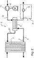
- eine schematische Darstellung einer ersten Ausführungsform der erfindungsgemäßen Abgasanlage in einem Fahrzeug,
- Fig. 3
- eine schematische Darstellung der zweiten Ausführungsform der erfindungsgemäßen Abgasanlage in einem Fahrzeug,
- Fig. 4a)
- einen Ausschnitt der Abgasanlage der ersten Ausführungsform in der Adsorptionskonfiguration,
- Fig. 4b)
- einen Ausschnitt der Abgasanlage der ersten Ausführungsform in der Durchlasskonfiguration,
- Fig. 5a)
- einen Ausschnitt der Abgasanlage der zweiten Ausführungsform in der Adsorptionskonfiguration und
- Fig. 5b)
- einen Ausschnitt der Abgasanlage der zweiten Ausführungsform in der Durchlasskonfiguration.
-
Fig. 1 zeigt eine schematische Darstellung des Fahrzeugs mit einem sich in einer Längsrichtung erstreckenden Fahrzeugkörper 1, der einen Hinterwagen 22 und einen Vorderwagen 21 umfasst. Im Vorderwagen 21 ist ein Brennstoffzellensystem 2 angeordnet. Das Brennstoffzellensystem 2 umfasst einen inFig. 1 nicht dargestellten Brennstoffzellenstapel 3, welcher kathodenseitig 21 zumindest mittelbar mit einer Abgasleitung 4 verbunden ist. Durch die Abgasleitung 4 ist ein aus dem Brennstoffzellenstapel 3 austretendes Fluid aus dem Vorderwagen 21 und damit aus dem Fahrzeugkörper 1 abführbar. Vorliegend ist das Fluid seitlich zur Längsrichtung aus dem Vorderwagen 21 des Fahrzeugs abführbar. - In
Fig. 2 ist eine erste Ausführungsform der erfindungsgemäßen Abgasanlage 8 in einem Fahrzeug dargestellt. Kathodenseitig wird das Kathodengas über einen mittels eines Antriebs 10 angetriebenen Verdichter 11 an einen Befeuchter 6 über eine Trockenzufuhrleitung 12 geleitet. Im Befeuchter 6 wird das Kathodengas befeuchtet und über eine Feuchtzufuhrleitung 5 in die Kathodenräume des Brennstoffzellenstapels 3 geführt. Am Kathodenaustritt 7 wird nicht reagiertes Kathodengas und Produktwasser über die Kathodenabgasleitung 9 zum Befeuchter 6 geleitet. Das Kathodengas wird unter anderem mit dem Produktwasser im Befeuchter 6 befeuchtet und den Kathoden zugeführt. Um einer Übersättigung des Befeuchters 6 entgegenzuwirken wird ein Teil des nicht reagierten Kathodengases und des Produktwassers als Fluid über die Abgasleitung 4 seitlich zur Längsachse oder zur Längsrichtung aus dem Fahrzeugkörper 1 geführt. - Die Abgasleitung 4 ist als Teil einer Abgasanlage 8 zu erachten, die eine Sorptionsanlage 13 umfasst zur Adsorption einer Flüssigkeit eines aus dem Brennstoffzellenstapel 3 austretenden Fluids. Die Sorptionsanlage 13 ist vorliegend als eine Lochscheibe gebildet, auf der Sorptionsmaterial, beispielsweise in Form von Schüttgut, aufgebracht ist. Die Abgasanlage 8 ist verstellbar zwischen einer Adsorptionskonfiguration und einer Durchlasskonfiguration. In der Adsorptionskonfiguration ist das aus den Kathodenräumen strömende und die Flüssigkeit enthaltende Fluid der Sorptionsanlage 13 zuführbar. Dabei wird die Flüssigkeit durch die Sorptionsanlage 13 adsorbiert. In der Durchlasskonfiguration ist das die Flüssigkeit enthaltende Fluid aus dem dem Vorderwagen 21, vorliegend aus dem Fahrzeugkörper 1, seitlich zur Längsrichtung des Fahrzeugs abführbar. Bevorzugt ist die Sorptionsanlage 13 zusätzlich ausgestaltet, adsorbierte Flüssigkeit in der Durchlasskonfiguration zu desorbieren, womit sie ebenfalls aus dem Vorderwagen 21 des Fahrzeugkörpers 1 ausgeführt werden kann.
- In der ersten Ausführungsform ist die Sorptionsanlage 13 innerhalb der Abgasleitung 4 angeordnet und verschwenkbar gelagert zwischen einer die Abgasanlage 8 in die Adsorptionskonfiguration versetzenden ersten Stellung 14 und einer die Abgasanlage 8 in die Durchlasskonfiguration versetzenden zweiten Stellung 15.
- In
Fig. 4a ) ist ein Ausschnitt der Abgasanlage mit der Sorptionsanlage 13 in der ersten Stellung 14 dargestellt. Die Abgasanlage 8 weist hierbei die Adsorptionskonfiguration auf. Die Sorptionsanlage 13 ist vorzugsweise ausgebildet und in der Abgasleitung 8 derart angeordnet, dass in der ersten Stellung 14 eine Innenwandung 16 der Abgasleitung 4 umfangsseitig abgedichtet ist. Die Sorptionsanlage 13 ist also derart in den Strömungsquerschnitt der Abgasleitung 4 geschwenkt, dass umfangsseitig zwischen der Sorptionsanlage 13 und der Abgasleitung 4 kein Fluid durchtreten kann. Die Strömung des Fluids erfolgt damit zwangsweise zur Sorptionsanlage 13. Die Flüssigkeit im Fluid wird in der Sorptionsanlage 13 adsorbiert. Vorzugsweise ist die Sorptionsanlage 13 dabei aber für den gasförmigen Teil des Fluids durchlässig. -
Fig. 4b ) zeigt einen Ausschnitt der Abgasanlage 8 in der Durchlasskonfiguration, in der sich die Sorptionsanlage 13 in der zweiten Stellung 15 befindet. Die Sorptionsanlage 13 ist zur Innenwandung 16 der Abgasleitung 4 verschwenkt und liegt vorzugsweise an ihr an. Somit wird die Abgasleitung 4 für ein Durchströmen des aus den Kathodenräumen stammenden Fluids freigegeben. -
Fig. 3 zeigt eine zweite Ausführungsform des erfindungsgemäßen Fahrzeugs, wobei die Abgasanlage 8 eine mit der Abgasleitung 4 verbundene und aus dem Vorderwagen 21 geführte, insbesondere seitlich zur Längsrichtung des Fahrzeugkörpers 1 orientierte, Bypassleitung 17 umfasst. In der Bypassleitung 17 ist ein als Ventil gebildetes Stellglied 18 angeordnet. Dieses ist verstellbar zwischen einer die Abgasanlage 8 in die Adsorptionskonfiguration versetzenden ersten Position 19 und einer die Abgasanlage 8 in die Durchlasskonfiguration versetzenden zweiten Position 20. - Ein Ausschnitt der Abgasanlage 8 der zweiten Ausführungsform in der Adsorptionskonfiguration ist in
Fig. 5a ) dargestellt. Diese zeigt das Stellglied 18 in einer die Bypassleitung 17 verschließenden ersten Position 19. Das Fluid wird hierbei der Sorptionsanlage 13 zugeführt, wobei dessen Flüssigkeit adsorbiert wird.Fig. 5b ) zeigt das Stellglied 18 in der die Bypassleitung 17 freigebenden zweiten Position 20. Das aus den Kathodenräumen strömende Fluid ist hierbei über die Bypassleitung 17 aus dem Vorderwagen 21 geführt. Die zweite Position 20 des Stellglieds 18 entspricht also der Durchlasskonfiguration der Abgasanlage 8. Zusätzlich kann die adsorbierte Flüssigkeit unter Einsatz eines der Sorptionsanlage 13 zugeordneten Heizelements desorbiert und ebenfalls über die Bypassleitung 17 und/oder die Abgasleitung 4 aus dem Fahrzeug an die Umgebung abgeleitet werden. In diesem Zusammenhang kann die Flüssigkeit auch verdampft werden, so dass der Dampf - anstelle einer Flüssigkeit - aus dem Fahrzeug geführt wird. - In einer nicht näher dargestellten Ausführungsform ist das Stellglied 18 in der Abgasleitung 17 derart angeordnet, dass die Bypassleitung 17 in der ersten Position 19 des Stellglieds 18 verschlossen ist. Der zur Sorptionsanlage 13 führende und als Sorptionsleitung gebildete Abschnitt der Abgasleitung 8 ist aber geöffnet oder zugänglich, so dass Flüssigkeit in der Sorptionsanlage 13 adsorbiert wird. In der zweiten Position 20 ist die Bypassleitung 17 geöffnet oder freigegeben, wobei die Sorptionsleitung geschlossen ist. Nun wird die durch die Sorptionsanlage 13 adsorbierte Flüssigkeit desorbiert und über die Abgasleitung 8 aus dem Vorderwagen 21, insbesondere seitlich zur Längsrichtung des Fahrzeugkörpers 1 geleitet. Dabei kann die desorbierte Flüssigkeit außerdem mittels eines nicht näher dargestellten Heizelements der Sorptionsanlage 13 verdampft werden, so dass nunmehr der Dampf - anstelle einer Flüssigkeit - über die Abgasleitung 8 an die Umgebung abgegeben wird.
- Das erfindungsgemäße Verfahren läuft wie folgt ab: Das eine Flüssigkeit enthaltende Fluid des Brennstoffzellensystems 2 wird der Abgasanlage 8 zugeführt. Die Abgasanlage 8 wird bei Unterschreiten einer vorgegebenen oder einer vorgebbaren Grenzgeschwindigkeit des Fahrzeugs in die Adsorptionskonfiguration verstellt, so dass die Flüssigkeit des Fluids durch die Sorptionsanlage 13 adsorbiert wird. Spätestens jedoch beim Stillstand oder beim Anhalten des Fahrzeugs wird die Abgasanlage 8 in die Adsorptionskonfiguration überführt. Dieser Vorgang kann beispielsweise mittels eines nicht näher gezeigten Controllers gesteuert werden.
- Das Verstellen der Abgasanlage 8 in die Adsorptionskonfiguration erfolgt bei der gezeigten ersten Ausführungsform, indem die Sorptionsanlage 13 in den Strömungsquerschnitt der Abgasleitung 4 geschwenkt und damit in die erste Stellung 14 verstellt wird. Das Verstellen der Abgasanlage 8 in die Adsorptionskonfiguration erfolgt bei der gezeigten zweiten Ausführungsform, indem die Bypassleitung 17 mittels des Stellglieds 18 geschlossen wird.
- Überschreitet das Fahrzeug eine vorgegebene oder vorgebbare Grenzgeschwindigkeit, so wird die Abgasanlage 8 in die Durchlasskonfiguration verstellt, wodurch das Fluid mittels der Abgasanlage 8 vorzugsweise seitlich zur Längsrichtung des Fahrzeugkörpers 1 aus dem Vorderwagen 21 abgeführt wird. Vorzugsweise wird gleichzeitig die in der Sorptionsanlage 13 adsorbierte Flüssigkeit desorbiert und über eine nicht näher gezeigte Heizeinheit - vorzugsweise dampfförmig - abgeführt.
- Bei der ersten Ausführungsform erfolgt das Verstellen der Abgasanlage 8 in die Durchlasskonfiguration durch Verschwenken der Sorptionsanlage 13 innerhalb der Abgasleitung 4 in die zweite Stellung 15. Bei der zweiten Ausführungsform erfolgt das Verstellen der Abgasanlage 8 in die Durchlasskonfiguration durch Öffnen oder Freigeben der Bypassleitung 17 mittels des Stellglieds 18. Vorzugsweise wird dabei desorbierte Flüssigkeit und/oder das Fluid über die Bypassleitung 17 aus dem Vorderwagen 21 geleitet.
-
- 1
- Fahrzeugkörper
- 2
- Brennstoffzellensystem
- 3
- Brennstoffzellenstapel
- 4
- Abgasleitung
- 5
- Feuchtzufuhrleitung
- 6
- Befeuchter
- 7
- Kathodenaustritt
- 8
- Abgasanlage
- 9
- Kathodenabgasleitung
- 10
- Antrieb
- 11
- Verdichter
- 12
- Trockenzufuhrleitung
- 13
- Sorptionsanlage
- 14
- Erste Stellung
- 15
- Zweite Stellung
- 16
- Innenwandung
- 17
- Bypassleitung
- 18
- Stellglied
- 19
- Erste Position
- 20
- Zweite Position
- 21
- Vorderwagen
- 22
- Hinterwagen
Claims (9)
- Fahrzeug mit einem Vorderwagen (21) und mit einem einen Brennstoffzellenstapel (3) aufweisenden Brennstoffzellensystem (2), das kathodenseitig zumindest mittelbar mit einer Abgasleitung (4) verbunden ist, durch welche ein aus dem Brennstoffzellenstapel (3) austretendes Fluid abführbar ist, wobei die Abgasleitung (4) einer Abgasanlage (8) zugeordnet ist, und die Abgasanlage (8) eine Sorptionsanlage (13) umfasst zur Adsorption einer Flüssigkeit des aus dem Brennstoffzellenstapel (3) austretenden Fluids, wobei die Abgasanlage (8) verstellbar ist zwischen einer Adsorptionskonfiguration, in der das die Flüssigkeit enthaltende Fluid der Sorptionsanlage (13) zuführbar und damit die Flüssigkeit durch diese adsorbierbar ist, und einer Durchlasskonfiguration, in der das die Flüssigkeit enthaltende Fluid abführbar ist, dadurch gekennzeichnet, dass das Brennstoffzellensystem (2) im Vorderwagen (21) angeordnet ist, dass in der Durchlasskonfiguration das aus dem Brennstoffzellenstapel (3) austretende Fluid aus dem Vorderwagen (21) abführbar ist, und dass die Abgasanlage (8) bei Unterschreiten einer vorgegebenen oder vorgebbaren Grenzgeschwindigkeit die Adsorptionskonfiguration und bei Überschreiten einer vorgegebenen oder vorgebbaren Grenzgeschwindigkeit die Durchlasskonfiguration aufweist.
- Fahrzeug nach Anspruch 1, dadurch gekennzeichnet, dass in der Durchlasskonfiguration der Abgasanlage (8) die in der Sorptionsanlage (13) adsorbierte Flüssigkeit desorbierbar und aus dem Vorderwagen (21) abführbar ist.
- Fahrzeug nach Anspruch 1 oder 2, dadurch gekennzeichnet, dass die Sorptionsanlage (13) innerhalb der Abgasleitung (4) angeordnet ist, und dass die Sorptionsanlage (13) verschwenkbar gelagert ist zwischen einer die Abgasanlage (8) in die Adsorptionskonfiguration versetzenden ersten Stellung (14) und einer die Abgasanlage (8) in die Durchlasskonfiguration versetzenden zweiten Stellung (15).
- Fahrzeug nach Anspruch 1 oder 2, dadurch gekennzeichnet, dass die Abgasanlage (8) eine mit der Abgasleitung (4) verbundene und aus dem Vorderwagen (21) geführte Bypassleitung (17) umfasst, in welcher ein Stellglied (18) angeordnet ist, das verstellbar ist zwischen einer die Abgasanlage (8) in die Adsorptionskonfiguration versetzenden ersten Position (19) und einer die Abgasanlage (8) in die Durchlasskonfiguration versetzenden zweiten Position (20).
- Fahrzeug nach einem der Ansprüche 1 bis 4, dadurch gekennzeichnet, dass der Brennstoffzellenstapel (3) kathodenaustrittsseitig (7) über eine Kathodenabgasleitung (9) mit einem Befeuchter (6) verbunden ist, mit dem befeuchteraustrittsseitig die die Sorptionsanlage (13) umfassende Abgasanlage (8) zumindest mittelbar verbunden ist.
- Verfahren zur Behandlung eines Fluids eines einen Brennstoffzellenstapel (3) aufweisenden Brennstoffzellensystems (2) bei einem Fahrzeug mit einem Vorderwagen (21), wobei eine eine Sorptionsanlage (13) aufweisende Abgasanlage vorgesehen ist, die kathodenseitig zumindest mittelbar mit dem Brennstoffzellenstapel (3) verbunden ist, dieses umfassend die folgenden Schritte:a) Zuführen des eine Flüssigkeit enthaltenden Fluids des Brennstoffzellensystems (2) an die Abgasanlage (8), undb) Verstellen der Abgasanlage (8) in eine Adsorptionskonfiguration und dadurch Adsorbieren der Flüssigkeit des Fluids mittels der Sorptionsanlage (13) bei Unterschreiten einer vorgegebenen oder vorgebbaren Grenzgeschwindigkeit des Fahrzeugs, oderc) Verstellen der Abgasanlage (8) in eine Durchlasskonfiguration und dadurch Abführen des Fluids mittels der Abgasanlage (8) aus dem Vorderwagen (21) des Fahrzeugs bei Überschreitung einer vorgegebenen oder vorgebbaren Grenzgeschwindigkeit.
- Verfahren nach Anspruch 6, dadurch gekennzeichnet, dass in der Durchlasskonfiguration die in der Sorptionsanlage (13) adsorbierte Flüssigkeit desorbiert und/oder abgeführt wird.
- Verfahren nach Anspruch 6 oder 7, gekennzeichnet durch:- Verstellen der Abgasanlage (8) in die Adsorptionskonfiguration durch Verschwenken der innerhalb einer Abgasleitung (4) der Abgasanlage (8) angeordneten Sorptionsanlage (13) in eine erste Stellung (14) oder- Verstellen der Abgasanlage (8) in die Durchlasskonfiguration durch Verschwenken der innerhalb einer Abgasleitung (4) der Abgasanlage (8) angeordneten Sorptionsanlage (13) in eine zweite Stellung (15).
- Verfahren nach Anspruch 6 oder 7, gekennzeichnet durch:- Verstellen der Abgasanlage (8) in die Adsorptionskonfiguration durch Verschließen einer mit einer Abgasleitung (4) der Abgasanlage (8) verbundenen Bypassleitung (17), oder,- Verstellen der Abgasanlage (8) in die Durchlasskonfiguration durch Öffnen einer mit der Abgasleitung (4) der Abgasanlage (8) verbundenen Bypassleitung (17), und Desorbieren und/oder Abführen der in der Sorptionsanlage (13) adsorbierten Flüssigkeit und/oder des Fluids über die Bypassleitung (17) aus dem Vorderwagen (21) des Fahrzeugs.
Applications Claiming Priority (2)
| Application Number | Priority Date | Filing Date | Title |
|---|---|---|---|
| DE102017221896.7A DE102017221896A1 (de) | 2017-12-05 | 2017-12-05 | Fahrzeug mit einem Brennstoffzellensystem und Verfahren zur Behandlung eines aus dem Brennstoffzellensystem austretenden Fluids |
| PCT/EP2018/076589 WO2019110165A1 (de) | 2017-12-05 | 2018-10-01 | Fahrzeug mit einem brennstoffzellensystem und verfahren zur behandlung eines aus dem brennstoffzellensystem austretenden fluids |
Publications (2)
| Publication Number | Publication Date |
|---|---|
| EP3649693A1 EP3649693A1 (de) | 2020-05-13 |
| EP3649693B1 true EP3649693B1 (de) | 2021-06-30 |
Family
ID=63787927
Family Applications (1)
| Application Number | Title | Priority Date | Filing Date |
|---|---|---|---|
| EP18782694.6A Active EP3649693B1 (de) | 2017-12-05 | 2018-10-01 | Fahrzeug mit einem brennstoffzellensystem und verfahren zur behandlung eines aus dem brennstoffzellensystem austretenden fluids |
Country Status (4)
| Country | Link |
|---|---|
| US (1) | US11217801B2 (de) |
| EP (1) | EP3649693B1 (de) |
| DE (1) | DE102017221896A1 (de) |
| WO (1) | WO2019110165A1 (de) |
Family Cites Families (10)
| Publication number | Priority date | Publication date | Assignee | Title |
|---|---|---|---|---|
| DE19918849C2 (de) | 1999-04-19 | 2003-04-30 | Mannesmann Ag | Vorrichtung zur Befeuchtung einer Brennstoffzellenmembran, sowie deren Verwendung |
| JP4622313B2 (ja) * | 2003-08-26 | 2011-02-02 | トヨタ自動車株式会社 | 移動体 |
| DE10351756A1 (de) | 2003-11-06 | 2005-06-23 | Daimlerchrysler Ag | Brennstoffzellensystem für den mobilen Einsatz mit einem Adsorptionsspeicher |
| DE102004051751B4 (de) | 2004-10-23 | 2015-11-05 | Robert Bosch Gmbh | Fahrzeug mit einer Brennstoffzellenanlage mit einem wasserhaltigen Fluidstrom |
| JP5460978B2 (ja) | 2007-07-11 | 2014-04-02 | ヤマハ発動機株式会社 | 燃料電池システム |
| US20100055508A1 (en) * | 2008-08-27 | 2010-03-04 | Idatech, Llc | Fuel cell systems with water recovery from fuel cell effluent |
| DE102009018401A1 (de) * | 2009-04-22 | 2010-10-28 | Airbus Deutschland Gmbh | System und Verfahren zum Kühlen eines Raums in einem Fahrzeug |
| DE102011114721A1 (de) * | 2011-10-01 | 2013-04-04 | Daimler Ag | Brennstoffzellensystem |
| DE102014204790B4 (de) * | 2014-03-14 | 2024-09-12 | Bayerische Motoren Werke Aktiengesellschaft | Brennstoffzellen-System mit Sorptionsspeicher im Abgasstrang |
| JP6104864B2 (ja) | 2014-09-02 | 2017-03-29 | 本田技研工業株式会社 | 燃料電池スタック及び燃料電池車両 |
-
2017
- 2017-12-05 DE DE102017221896.7A patent/DE102017221896A1/de not_active Withdrawn
-
2018
- 2018-10-01 EP EP18782694.6A patent/EP3649693B1/de active Active
- 2018-10-01 US US16/770,037 patent/US11217801B2/en active Active
- 2018-10-01 WO PCT/EP2018/076589 patent/WO2019110165A1/de not_active Ceased
Also Published As
| Publication number | Publication date |
|---|---|
| US11217801B2 (en) | 2022-01-04 |
| DE102017221896A1 (de) | 2019-06-06 |
| US20200388864A1 (en) | 2020-12-10 |
| WO2019110165A1 (de) | 2019-06-13 |
| EP3649693A1 (de) | 2020-05-13 |
Similar Documents
| Publication | Publication Date | Title |
|---|---|---|
| DE102010055318B4 (de) | Verfahren und Einrichtung zur Steuerung des Drucks im Inneren eines Kraftstofftanks | |
| EP2394330A2 (de) | Batteriemodul | |
| EP3622207B1 (de) | Ventilmodul | |
| WO2016026696A1 (de) | Ventileinheit mit spülluftpumpe | |
| DE102010055312B4 (de) | Einrichtung zur Entlüftung und Belüftung eines Kraftstofftanks | |
| EP2686215B1 (de) | Lufttrockneradaptermodul, lufttrocknermodul und druckluftversorgungseinrichtung | |
| DE102010055316A1 (de) | Einrichtung zur Entlüftung und Belüftung eines Kraftstofftanks | |
| DE102016004381B4 (de) | Kraftstoffdampfverarbeitungsvorrichtung | |
| EP3649693B1 (de) | Fahrzeug mit einem brennstoffzellensystem und verfahren zur behandlung eines aus dem brennstoffzellensystem austretenden fluids | |
| EP4637960A1 (de) | Modulare co2-adsorptionsvorrichtung zum trennen von co2 aus einem zugeführten luftstrom mittels eines adsorptions-desorptions-vorgangs | |
| WO2002057615A1 (de) | Einrichtung und verfahren zur vermeidung des austritts von kraftstoffdämpfen aus einem ansaugsystem einer brennkraftmaschine | |
| EP3458177B1 (de) | Kraftstoffdampffilter für eine tankentlüftungseinrichtung eines kraftfahrzeugs mit verbesserten beladeeigenschaften | |
| EP3358160B1 (de) | Brennkraftmaschine mit einer sekundärluftpumpe und verfahren zum betreiben einer brennkraftmaschine mit einer sekundärluftpumpe | |
| EP1604845B1 (de) | Luftfederungseinrichtung für Fahrzeuge, insbesondere für Nutzfahrzeuge | |
| DE2056087B2 (de) | ||
| DE102022130004A1 (de) | Prozessraum und Anlage zur Abtrennung von Kohlenstoffdioxid aus der Umgebungsluft | |
| WO2007098936A1 (de) | Trockenvorrichtung für druckluft und andere gasförmige medien und verfahren zum betreiben einer solchen | |
| DE10233762A1 (de) | Vorrichtung zur Klimatisierung von Kraftfahrzeugen | |
| DE102008009571A1 (de) | Anlage zum Zwischenspeichern von aus einem Fahrzeug-Kraftstofftank entweichenden Kraftstoffdämpfen | |
| DE102020134016A1 (de) | Vorrichtung zum spülen von kraftstoffverdampfungsgas in einem kraftstoffsystem | |
| DE102010026367B4 (de) | Entlüftungseinrichtung für einen Kraftstofftank und Verfahren zum Betreiben einer Entlüftungseinrichtung | |
| DE102019202383A1 (de) | Verfahren zum Betreiben einer Antriebseinrichtung für ein Kraftfahrzeug sowie entsprechende Antriebseinrichtung | |
| DE102024205163A1 (de) | Drehventil zum Einstellen einer Durchflussmenge eines schüttfähigen CO2-Abtrennungsmittels und CO2-Abtrennungsvorrichtung | |
| EP1743788B1 (de) | Fahrzeugtemperiersystem | |
| DE102018125949A1 (de) | System zur Wassergewinnung aus einem Abgas einer Verbrennungskraftmaschine |
Legal Events
| Date | Code | Title | Description |
|---|---|---|---|
| STAA | Information on the status of an ep patent application or granted ep patent |
Free format text: STATUS: UNKNOWN |
|
| STAA | Information on the status of an ep patent application or granted ep patent |
Free format text: STATUS: THE INTERNATIONAL PUBLICATION HAS BEEN MADE |
|
| PUAI | Public reference made under article 153(3) epc to a published international application that has entered the european phase |
Free format text: ORIGINAL CODE: 0009012 |
|
| STAA | Information on the status of an ep patent application or granted ep patent |
Free format text: STATUS: REQUEST FOR EXAMINATION WAS MADE |
|
| 17P | Request for examination filed |
Effective date: 20200206 |
|
| AK | Designated contracting states |
Kind code of ref document: A1 Designated state(s): AL AT BE BG CH CY CZ DE DK EE ES FI FR GB GR HR HU IE IS IT LI LT LU LV MC MK MT NL NO PL PT RO RS SE SI SK SM TR |
|
| AX | Request for extension of the european patent |
Extension state: BA ME |
|
| GRAP | Despatch of communication of intention to grant a patent |
Free format text: ORIGINAL CODE: EPIDOSNIGR1 |
|
| RIC1 | Information provided on ipc code assigned before grant |
Ipc: B60K 1/04 20190101ALI20201223BHEP Ipc: B60K 13/04 20060101ALI20201223BHEP Ipc: H01M 8/04119 20160101AFI20201223BHEP Ipc: B60L 50/72 20190101ALI20201223BHEP Ipc: B60L 50/71 20190101ALI20201223BHEP |
|
| STAA | Information on the status of an ep patent application or granted ep patent |
Free format text: STATUS: GRANT OF PATENT IS INTENDED |
|
| DAV | Request for validation of the european patent (deleted) | ||
| DAX | Request for extension of the european patent (deleted) | ||
| INTG | Intention to grant announced |
Effective date: 20210128 |
|
| GRAJ | Information related to disapproval of communication of intention to grant by the applicant or resumption of examination proceedings by the epo deleted |
Free format text: ORIGINAL CODE: EPIDOSDIGR1 |
|
| STAA | Information on the status of an ep patent application or granted ep patent |
Free format text: STATUS: REQUEST FOR EXAMINATION WAS MADE |
|
| INTC | Intention to grant announced (deleted) | ||
| GRAP | Despatch of communication of intention to grant a patent |
Free format text: ORIGINAL CODE: EPIDOSNIGR1 |
|
| STAA | Information on the status of an ep patent application or granted ep patent |
Free format text: STATUS: GRANT OF PATENT IS INTENDED |
|
| GRAS | Grant fee paid |
Free format text: ORIGINAL CODE: EPIDOSNIGR3 |
|
| INTG | Intention to grant announced |
Effective date: 20210429 |
|
| GRAA | (expected) grant |
Free format text: ORIGINAL CODE: 0009210 |
|
| STAA | Information on the status of an ep patent application or granted ep patent |
Free format text: STATUS: THE PATENT HAS BEEN GRANTED |
|
| AK | Designated contracting states |
Kind code of ref document: B1 Designated state(s): AL AT BE BG CH CY CZ DE DK EE ES FI FR GB GR HR HU IE IS IT LI LT LU LV MC MK MT NL NO PL PT RO RS SE SI SK SM TR |
|
| REG | Reference to a national code |
Ref country code: CH Ref legal event code: EP |
|
| REG | Reference to a national code |
Ref country code: AT Ref legal event code: REF Ref document number: 1407186 Country of ref document: AT Kind code of ref document: T Effective date: 20210715 |
|
| REG | Reference to a national code |
Ref country code: DE Ref legal event code: R096 Ref document number: 502018005947 Country of ref document: DE |
|
| REG | Reference to a national code |
Ref country code: IE Ref legal event code: FG4D Free format text: LANGUAGE OF EP DOCUMENT: GERMAN |
|
| REG | Reference to a national code |
Ref country code: LT Ref legal event code: MG9D |
|
| PG25 | Lapsed in a contracting state [announced via postgrant information from national office to epo] |
Ref country code: HR Free format text: LAPSE BECAUSE OF FAILURE TO SUBMIT A TRANSLATION OF THE DESCRIPTION OR TO PAY THE FEE WITHIN THE PRESCRIBED TIME-LIMIT Effective date: 20210630 Ref country code: FI Free format text: LAPSE BECAUSE OF FAILURE TO SUBMIT A TRANSLATION OF THE DESCRIPTION OR TO PAY THE FEE WITHIN THE PRESCRIBED TIME-LIMIT Effective date: 20210630 Ref country code: BG Free format text: LAPSE BECAUSE OF FAILURE TO SUBMIT A TRANSLATION OF THE DESCRIPTION OR TO PAY THE FEE WITHIN THE PRESCRIBED TIME-LIMIT Effective date: 20210930 |
|
| REG | Reference to a national code |
Ref country code: NL Ref legal event code: MP Effective date: 20210630 |
|
| PG25 | Lapsed in a contracting state [announced via postgrant information from national office to epo] |
Ref country code: RS Free format text: LAPSE BECAUSE OF FAILURE TO SUBMIT A TRANSLATION OF THE DESCRIPTION OR TO PAY THE FEE WITHIN THE PRESCRIBED TIME-LIMIT Effective date: 20210630 Ref country code: SE Free format text: LAPSE BECAUSE OF FAILURE TO SUBMIT A TRANSLATION OF THE DESCRIPTION OR TO PAY THE FEE WITHIN THE PRESCRIBED TIME-LIMIT Effective date: 20210630 Ref country code: NO Free format text: LAPSE BECAUSE OF FAILURE TO SUBMIT A TRANSLATION OF THE DESCRIPTION OR TO PAY THE FEE WITHIN THE PRESCRIBED TIME-LIMIT Effective date: 20210930 Ref country code: LV Free format text: LAPSE BECAUSE OF FAILURE TO SUBMIT A TRANSLATION OF THE DESCRIPTION OR TO PAY THE FEE WITHIN THE PRESCRIBED TIME-LIMIT Effective date: 20210630 Ref country code: GR Free format text: LAPSE BECAUSE OF FAILURE TO SUBMIT A TRANSLATION OF THE DESCRIPTION OR TO PAY THE FEE WITHIN THE PRESCRIBED TIME-LIMIT Effective date: 20211001 |
|
| PG25 | Lapsed in a contracting state [announced via postgrant information from national office to epo] |
Ref country code: EE Free format text: LAPSE BECAUSE OF FAILURE TO SUBMIT A TRANSLATION OF THE DESCRIPTION OR TO PAY THE FEE WITHIN THE PRESCRIBED TIME-LIMIT Effective date: 20210630 Ref country code: ES Free format text: LAPSE BECAUSE OF FAILURE TO SUBMIT A TRANSLATION OF THE DESCRIPTION OR TO PAY THE FEE WITHIN THE PRESCRIBED TIME-LIMIT Effective date: 20210630 Ref country code: SK Free format text: LAPSE BECAUSE OF FAILURE TO SUBMIT A TRANSLATION OF THE DESCRIPTION OR TO PAY THE FEE WITHIN THE PRESCRIBED TIME-LIMIT Effective date: 20210630 Ref country code: CZ Free format text: LAPSE BECAUSE OF FAILURE TO SUBMIT A TRANSLATION OF THE DESCRIPTION OR TO PAY THE FEE WITHIN THE PRESCRIBED TIME-LIMIT Effective date: 20210630 Ref country code: PT Free format text: LAPSE BECAUSE OF FAILURE TO SUBMIT A TRANSLATION OF THE DESCRIPTION OR TO PAY THE FEE WITHIN THE PRESCRIBED TIME-LIMIT Effective date: 20211102 Ref country code: NL Free format text: LAPSE BECAUSE OF FAILURE TO SUBMIT A TRANSLATION OF THE DESCRIPTION OR TO PAY THE FEE WITHIN THE PRESCRIBED TIME-LIMIT Effective date: 20210630 Ref country code: RO Free format text: LAPSE BECAUSE OF FAILURE TO SUBMIT A TRANSLATION OF THE DESCRIPTION OR TO PAY THE FEE WITHIN THE PRESCRIBED TIME-LIMIT Effective date: 20210630 Ref country code: SM Free format text: LAPSE BECAUSE OF FAILURE TO SUBMIT A TRANSLATION OF THE DESCRIPTION OR TO PAY THE FEE WITHIN THE PRESCRIBED TIME-LIMIT Effective date: 20210630 |
|
| PG25 | Lapsed in a contracting state [announced via postgrant information from national office to epo] |
Ref country code: PL Free format text: LAPSE BECAUSE OF FAILURE TO SUBMIT A TRANSLATION OF THE DESCRIPTION OR TO PAY THE FEE WITHIN THE PRESCRIBED TIME-LIMIT Effective date: 20210630 |
|
| REG | Reference to a national code |
Ref country code: DE Ref legal event code: R097 Ref document number: 502018005947 Country of ref document: DE |
|
| PG25 | Lapsed in a contracting state [announced via postgrant information from national office to epo] |
Ref country code: DK Free format text: LAPSE BECAUSE OF FAILURE TO SUBMIT A TRANSLATION OF THE DESCRIPTION OR TO PAY THE FEE WITHIN THE PRESCRIBED TIME-LIMIT Effective date: 20210630 |
|
| PLBE | No opposition filed within time limit |
Free format text: ORIGINAL CODE: 0009261 |
|
| STAA | Information on the status of an ep patent application or granted ep patent |
Free format text: STATUS: NO OPPOSITION FILED WITHIN TIME LIMIT |
|
| REG | Reference to a national code |
Ref country code: CH Ref legal event code: PL |
|
| PG25 | Lapsed in a contracting state [announced via postgrant information from national office to epo] |
Ref country code: AL Free format text: LAPSE BECAUSE OF FAILURE TO SUBMIT A TRANSLATION OF THE DESCRIPTION OR TO PAY THE FEE WITHIN THE PRESCRIBED TIME-LIMIT Effective date: 20210630 |
|
| 26N | No opposition filed |
Effective date: 20220331 |
|
| REG | Reference to a national code |
Ref country code: BE Ref legal event code: MM Effective date: 20211031 |
|
| PG25 | Lapsed in a contracting state [announced via postgrant information from national office to epo] |
Ref country code: MC Free format text: LAPSE BECAUSE OF FAILURE TO SUBMIT A TRANSLATION OF THE DESCRIPTION OR TO PAY THE FEE WITHIN THE PRESCRIBED TIME-LIMIT Effective date: 20210630 |
|
| PG25 | Lapsed in a contracting state [announced via postgrant information from national office to epo] |
Ref country code: LU Free format text: LAPSE BECAUSE OF NON-PAYMENT OF DUE FEES Effective date: 20211001 Ref country code: IT Free format text: LAPSE BECAUSE OF FAILURE TO SUBMIT A TRANSLATION OF THE DESCRIPTION OR TO PAY THE FEE WITHIN THE PRESCRIBED TIME-LIMIT Effective date: 20210630 Ref country code: BE Free format text: LAPSE BECAUSE OF NON-PAYMENT OF DUE FEES Effective date: 20211031 |
|
| PG25 | Lapsed in a contracting state [announced via postgrant information from national office to epo] |
Ref country code: LI Free format text: LAPSE BECAUSE OF NON-PAYMENT OF DUE FEES Effective date: 20211031 Ref country code: CH Free format text: LAPSE BECAUSE OF NON-PAYMENT OF DUE FEES Effective date: 20211031 |
|
| PG25 | Lapsed in a contracting state [announced via postgrant information from national office to epo] |
Ref country code: IE Free format text: LAPSE BECAUSE OF NON-PAYMENT OF DUE FEES Effective date: 20211001 |
|
| PG25 | Lapsed in a contracting state [announced via postgrant information from national office to epo] |
Ref country code: LT Free format text: LAPSE BECAUSE OF FAILURE TO SUBMIT A TRANSLATION OF THE DESCRIPTION OR TO PAY THE FEE WITHIN THE PRESCRIBED TIME-LIMIT Effective date: 20210630 |
|
| PG25 | Lapsed in a contracting state [announced via postgrant information from national office to epo] |
Ref country code: CY Free format text: LAPSE BECAUSE OF FAILURE TO SUBMIT A TRANSLATION OF THE DESCRIPTION OR TO PAY THE FEE WITHIN THE PRESCRIBED TIME-LIMIT Effective date: 20210630 |
|
| P01 | Opt-out of the competence of the unified patent court (upc) registered |
Effective date: 20230530 |
|
| PG25 | Lapsed in a contracting state [announced via postgrant information from national office to epo] |
Ref country code: HU Free format text: LAPSE BECAUSE OF FAILURE TO SUBMIT A TRANSLATION OF THE DESCRIPTION OR TO PAY THE FEE WITHIN THE PRESCRIBED TIME-LIMIT; INVALID AB INITIO Effective date: 20181001 |
|
| PG25 | Lapsed in a contracting state [announced via postgrant information from national office to epo] |
Ref country code: MK Free format text: LAPSE BECAUSE OF FAILURE TO SUBMIT A TRANSLATION OF THE DESCRIPTION OR TO PAY THE FEE WITHIN THE PRESCRIBED TIME-LIMIT Effective date: 20210630 |
|
| PG25 | Lapsed in a contracting state [announced via postgrant information from national office to epo] |
Ref country code: MT Free format text: LAPSE BECAUSE OF FAILURE TO SUBMIT A TRANSLATION OF THE DESCRIPTION OR TO PAY THE FEE WITHIN THE PRESCRIBED TIME-LIMIT Effective date: 20210630 |
|
| REG | Reference to a national code |
Ref country code: AT Ref legal event code: MM01 Ref document number: 1407186 Country of ref document: AT Kind code of ref document: T Effective date: 20231001 |
|
| PG25 | Lapsed in a contracting state [announced via postgrant information from national office to epo] |
Ref country code: AT Free format text: LAPSE BECAUSE OF NON-PAYMENT OF DUE FEES Effective date: 20231001 |
|
| PG25 | Lapsed in a contracting state [announced via postgrant information from national office to epo] |
Ref country code: AT Free format text: LAPSE BECAUSE OF NON-PAYMENT OF DUE FEES Effective date: 20231001 |
|
| PG25 | Lapsed in a contracting state [announced via postgrant information from national office to epo] |
Ref country code: TR Free format text: LAPSE BECAUSE OF FAILURE TO SUBMIT A TRANSLATION OF THE DESCRIPTION OR TO PAY THE FEE WITHIN THE PRESCRIBED TIME-LIMIT Effective date: 20210630 |
|
| PGFP | Annual fee paid to national office [announced via postgrant information from national office to epo] |
Ref country code: DE Payment date: 20251031 Year of fee payment: 8 |
|
| PGFP | Annual fee paid to national office [announced via postgrant information from national office to epo] |
Ref country code: GB Payment date: 20251024 Year of fee payment: 8 |
|
| PGFP | Annual fee paid to national office [announced via postgrant information from national office to epo] |
Ref country code: FR Payment date: 20251024 Year of fee payment: 8 |
|
| PGFP | Annual fee paid to national office [announced via postgrant information from national office to epo] |
Ref country code: AT Payment date: 20260410 Year of fee payment: 5 |