EP3649009B1 - Pressure sensing system and seat cushion having the pressure sensing system - Google Patents
Pressure sensing system and seat cushion having the pressure sensing system Download PDFInfo
- Publication number
- EP3649009B1 EP3649009B1 EP18746431.8A EP18746431A EP3649009B1 EP 3649009 B1 EP3649009 B1 EP 3649009B1 EP 18746431 A EP18746431 A EP 18746431A EP 3649009 B1 EP3649009 B1 EP 3649009B1
- Authority
- EP
- European Patent Office
- Prior art keywords
- foam
- printed circuit
- seat cushion
- flexible printed
- electrically conductive
- Prior art date
- Legal status (The legal status is an assumption and is not a legal conclusion. Google has not performed a legal analysis and makes no representation as to the accuracy of the status listed.)
- Active
Links
Images






Classifications
-
- B—PERFORMING OPERATIONS; TRANSPORTING
- B60—VEHICLES IN GENERAL
- B60R—VEHICLES, VEHICLE FITTINGS, OR VEHICLE PARTS, NOT OTHERWISE PROVIDED FOR
- B60R22/00—Safety belts or body harnesses in vehicles
- B60R22/48—Control systems, alarms, or interlock systems, for the correct application of the belt or harness
-
- B—PERFORMING OPERATIONS; TRANSPORTING
- B29—WORKING OF PLASTICS; WORKING OF SUBSTANCES IN A PLASTIC STATE IN GENERAL
- B29C—SHAPING OR JOINING OF PLASTICS; SHAPING OF MATERIAL IN A PLASTIC STATE, NOT OTHERWISE PROVIDED FOR; AFTER-TREATMENT OF THE SHAPED PRODUCTS, e.g. REPAIRING
- B29C33/00—Moulds or cores; Details thereof or accessories therefor
- B29C33/12—Moulds or cores; Details thereof or accessories therefor with incorporated means for positioning inserts, e.g. labels
- B29C33/123—Moulds or cores; Details thereof or accessories therefor with incorporated means for positioning inserts, e.g. labels for centering the inserts
-
- B—PERFORMING OPERATIONS; TRANSPORTING
- B29—WORKING OF PLASTICS; WORKING OF SUBSTANCES IN A PLASTIC STATE IN GENERAL
- B29C—SHAPING OR JOINING OF PLASTICS; SHAPING OF MATERIAL IN A PLASTIC STATE, NOT OTHERWISE PROVIDED FOR; AFTER-TREATMENT OF THE SHAPED PRODUCTS, e.g. REPAIRING
- B29C44/00—Shaping by internal pressure generated in the material, e.g. swelling or foaming ; Producing porous or cellular expanded plastics articles
- B29C44/02—Shaping by internal pressure generated in the material, e.g. swelling or foaming ; Producing porous or cellular expanded plastics articles for articles of definite length, i.e. discrete articles
- B29C44/12—Incorporating or moulding on preformed parts, e.g. inserts or reinforcements
- B29C44/1266—Incorporating or moulding on preformed parts, e.g. inserts or reinforcements the preformed part being completely encapsulated, e.g. for packaging purposes or as reinforcement
-
- B—PERFORMING OPERATIONS; TRANSPORTING
- B29—WORKING OF PLASTICS; WORKING OF SUBSTANCES IN A PLASTIC STATE IN GENERAL
- B29C—SHAPING OR JOINING OF PLASTICS; SHAPING OF MATERIAL IN A PLASTIC STATE, NOT OTHERWISE PROVIDED FOR; AFTER-TREATMENT OF THE SHAPED PRODUCTS, e.g. REPAIRING
- B29C45/00—Injection moulding, i.e. forcing the required volume of moulding material through a nozzle into a closed mould; Apparatus therefor
- B29C45/14—Injection moulding, i.e. forcing the required volume of moulding material through a nozzle into a closed mould; Apparatus therefor incorporating preformed parts or layers, e.g. injection moulding around inserts or for coating articles
- B29C45/14065—Positioning or centering articles in the mould
-
- B—PERFORMING OPERATIONS; TRANSPORTING
- B29—WORKING OF PLASTICS; WORKING OF SUBSTANCES IN A PLASTIC STATE IN GENERAL
- B29C—SHAPING OR JOINING OF PLASTICS; SHAPING OF MATERIAL IN A PLASTIC STATE, NOT OTHERWISE PROVIDED FOR; AFTER-TREATMENT OF THE SHAPED PRODUCTS, e.g. REPAIRING
- B29C45/00—Injection moulding, i.e. forcing the required volume of moulding material through a nozzle into a closed mould; Apparatus therefor
- B29C45/17—Component parts, details or accessories; Auxiliary operations
- B29C45/26—Moulds
-
- B—PERFORMING OPERATIONS; TRANSPORTING
- B60—VEHICLES IN GENERAL
- B60N—SEATS SPECIALLY ADAPTED FOR VEHICLES; VEHICLE PASSENGER ACCOMMODATION NOT OTHERWISE PROVIDED FOR
- B60N2/00—Seats specially adapted for vehicles; Arrangement or mounting of seats in vehicles
- B60N2/002—Seats provided with an occupancy detection means mounted therein or thereon
-
- B—PERFORMING OPERATIONS; TRANSPORTING
- B60—VEHICLES IN GENERAL
- B60N—SEATS SPECIALLY ADAPTED FOR VEHICLES; VEHICLE PASSENGER ACCOMMODATION NOT OTHERWISE PROVIDED FOR
- B60N2/00—Seats specially adapted for vehicles; Arrangement or mounting of seats in vehicles
- B60N2/002—Seats provided with an occupancy detection means mounted therein or thereon
- B60N2/0021—Seats provided with an occupancy detection means mounted therein or thereon characterised by the type of sensor or measurement
- B60N2/0024—Seats provided with an occupancy detection means mounted therein or thereon characterised by the type of sensor or measurement for identifying, categorising or investigation of the occupant or object on the seat
- B60N2/0025—Seats provided with an occupancy detection means mounted therein or thereon characterised by the type of sensor or measurement for identifying, categorising or investigation of the occupant or object on the seat by using weight measurement
-
- B—PERFORMING OPERATIONS; TRANSPORTING
- B60—VEHICLES IN GENERAL
- B60N—SEATS SPECIALLY ADAPTED FOR VEHICLES; VEHICLE PASSENGER ACCOMMODATION NOT OTHERWISE PROVIDED FOR
- B60N2/00—Seats specially adapted for vehicles; Arrangement or mounting of seats in vehicles
- B60N2/002—Seats provided with an occupancy detection means mounted therein or thereon
- B60N2/0021—Seats provided with an occupancy detection means mounted therein or thereon characterised by the type of sensor or measurement
- B60N2/0024—Seats provided with an occupancy detection means mounted therein or thereon characterised by the type of sensor or measurement for identifying, categorising or investigation of the occupant or object on the seat
- B60N2/0026—Seats provided with an occupancy detection means mounted therein or thereon characterised by the type of sensor or measurement for identifying, categorising or investigation of the occupant or object on the seat for distinguishing between humans, animals or objects
-
- B—PERFORMING OPERATIONS; TRANSPORTING
- B60—VEHICLES IN GENERAL
- B60N—SEATS SPECIALLY ADAPTED FOR VEHICLES; VEHICLE PASSENGER ACCOMMODATION NOT OTHERWISE PROVIDED FOR
- B60N2/00—Seats specially adapted for vehicles; Arrangement or mounting of seats in vehicles
- B60N2/002—Seats provided with an occupancy detection means mounted therein or thereon
- B60N2/0021—Seats provided with an occupancy detection means mounted therein or thereon characterised by the type of sensor or measurement
- B60N2/003—Seats provided with an occupancy detection means mounted therein or thereon characterised by the type of sensor or measurement characterised by the sensor mounting location in or on the seat
- B60N2/0033—Seats provided with an occupancy detection means mounted therein or thereon characterised by the type of sensor or measurement characterised by the sensor mounting location in or on the seat mounted on or in the foam cushion
-
- B—PERFORMING OPERATIONS; TRANSPORTING
- B60—VEHICLES IN GENERAL
- B60N—SEATS SPECIALLY ADAPTED FOR VEHICLES; VEHICLE PASSENGER ACCOMMODATION NOT OTHERWISE PROVIDED FOR
- B60N2/00—Seats specially adapted for vehicles; Arrangement or mounting of seats in vehicles
- B60N2/70—Upholstery springs ; Upholstery
- B60N2/7017—Upholstery springs ; Upholstery characterised by the manufacturing process; manufacturing upholstery or upholstery springs not otherwise provided for
-
- B—PERFORMING OPERATIONS; TRANSPORTING
- B60—VEHICLES IN GENERAL
- B60R—VEHICLES, VEHICLE FITTINGS, OR VEHICLE PARTS, NOT OTHERWISE PROVIDED FOR
- B60R21/00—Arrangements or fittings on vehicles for protecting or preventing injuries to occupants or pedestrians in case of accidents or other traffic risks
- B60R21/01—Electrical circuits for triggering passive safety arrangements, e.g. airbags, safety belt tighteners, in case of vehicle accidents or impending vehicle accidents
-
- G—PHYSICS
- G01—MEASURING; TESTING
- G01L—MEASURING FORCE, STRESS, TORQUE, WORK, MECHANICAL POWER, MECHANICAL EFFICIENCY, OR FLUID PRESSURE
- G01L1/00—Measuring force or stress, in general
- G01L1/20—Measuring force or stress, in general by measuring variations in ohmic resistance of solid materials or of electrically-conductive fluids; by making use of electrokinetic cells, i.e. liquid-containing cells wherein an electrical potential is produced or varied upon the application of stress
- G01L1/205—Measuring force or stress, in general by measuring variations in ohmic resistance of solid materials or of electrically-conductive fluids; by making use of electrokinetic cells, i.e. liquid-containing cells wherein an electrical potential is produced or varied upon the application of stress using distributed sensing elements
-
- H—ELECTRICITY
- H05—ELECTRIC TECHNIQUES NOT OTHERWISE PROVIDED FOR
- H05K—PRINTED CIRCUITS; CASINGS OR CONSTRUCTIONAL DETAILS OF ELECTRIC APPARATUS; MANUFACTURE OF ASSEMBLAGES OF ELECTRICAL COMPONENTS
- H05K1/00—Printed circuits
- H05K1/02—Details
- H05K1/0296—Conductive pattern lay-out details not covered by sub groups H05K1/02 - H05K1/0295
-
- H—ELECTRICITY
- H05—ELECTRIC TECHNIQUES NOT OTHERWISE PROVIDED FOR
- H05K—PRINTED CIRCUITS; CASINGS OR CONSTRUCTIONAL DETAILS OF ELECTRIC APPARATUS; MANUFACTURE OF ASSEMBLAGES OF ELECTRICAL COMPONENTS
- H05K1/00—Printed circuits
- H05K1/02—Details
- H05K1/03—Use of materials for the substrate
- H05K1/0313—Organic insulating material
- H05K1/032—Organic insulating material consisting of one material
-
- H—ELECTRICITY
- H05—ELECTRIC TECHNIQUES NOT OTHERWISE PROVIDED FOR
- H05K—PRINTED CIRCUITS; CASINGS OR CONSTRUCTIONAL DETAILS OF ELECTRIC APPARATUS; MANUFACTURE OF ASSEMBLAGES OF ELECTRICAL COMPONENTS
- H05K1/00—Printed circuits
- H05K1/02—Details
- H05K1/03—Use of materials for the substrate
- H05K1/0393—Flexible materials
-
- B—PERFORMING OPERATIONS; TRANSPORTING
- B29—WORKING OF PLASTICS; WORKING OF SUBSTANCES IN A PLASTIC STATE IN GENERAL
- B29C—SHAPING OR JOINING OF PLASTICS; SHAPING OF MATERIAL IN A PLASTIC STATE, NOT OTHERWISE PROVIDED FOR; AFTER-TREATMENT OF THE SHAPED PRODUCTS, e.g. REPAIRING
- B29C45/00—Injection moulding, i.e. forcing the required volume of moulding material through a nozzle into a closed mould; Apparatus therefor
- B29C45/14—Injection moulding, i.e. forcing the required volume of moulding material through a nozzle into a closed mould; Apparatus therefor incorporating preformed parts or layers, e.g. injection moulding around inserts or for coating articles
- B29C45/14065—Positioning or centering articles in the mould
- B29C2045/14147—Positioning or centering articles in the mould using pins or needles penetrating through the insert
-
- B—PERFORMING OPERATIONS; TRANSPORTING
- B29—WORKING OF PLASTICS; WORKING OF SUBSTANCES IN A PLASTIC STATE IN GENERAL
- B29C—SHAPING OR JOINING OF PLASTICS; SHAPING OF MATERIAL IN A PLASTIC STATE, NOT OTHERWISE PROVIDED FOR; AFTER-TREATMENT OF THE SHAPED PRODUCTS, e.g. REPAIRING
- B29C44/00—Shaping by internal pressure generated in the material, e.g. swelling or foaming ; Producing porous or cellular expanded plastics articles
- B29C44/34—Auxiliary operations
- B29C44/58—Moulds
- B29C44/583—Moulds for making articles with cavities
-
- B—PERFORMING OPERATIONS; TRANSPORTING
- B29—WORKING OF PLASTICS; WORKING OF SUBSTANCES IN A PLASTIC STATE IN GENERAL
- B29K—INDEXING SCHEME ASSOCIATED WITH SUBCLASSES B29B, B29C OR B29D, RELATING TO MOULDING MATERIALS OR TO MATERIALS FOR MOULDS, REINFORCEMENTS, FILLERS OR PREFORMED PARTS, e.g. INSERTS
- B29K2075/00—Use of PU, i.e. polyureas or polyurethanes or derivatives thereof, as moulding material
-
- B—PERFORMING OPERATIONS; TRANSPORTING
- B29—WORKING OF PLASTICS; WORKING OF SUBSTANCES IN A PLASTIC STATE IN GENERAL
- B29K—INDEXING SCHEME ASSOCIATED WITH SUBCLASSES B29B, B29C OR B29D, RELATING TO MOULDING MATERIALS OR TO MATERIALS FOR MOULDS, REINFORCEMENTS, FILLERS OR PREFORMED PARTS, e.g. INSERTS
- B29K2105/00—Condition, form or state of moulded material or of the material to be shaped
- B29K2105/04—Condition, form or state of moulded material or of the material to be shaped cellular or porous
-
- B—PERFORMING OPERATIONS; TRANSPORTING
- B29—WORKING OF PLASTICS; WORKING OF SUBSTANCES IN A PLASTIC STATE IN GENERAL
- B29K—INDEXING SCHEME ASSOCIATED WITH SUBCLASSES B29B, B29C OR B29D, RELATING TO MOULDING MATERIALS OR TO MATERIALS FOR MOULDS, REINFORCEMENTS, FILLERS OR PREFORMED PARTS, e.g. INSERTS
- B29K2667/00—Use of polyesters or derivatives thereof for preformed parts, e.g. for inserts
- B29K2667/003—PET, i.e. poylethylene terephthalate
-
- B—PERFORMING OPERATIONS; TRANSPORTING
- B29—WORKING OF PLASTICS; WORKING OF SUBSTANCES IN A PLASTIC STATE IN GENERAL
- B29K—INDEXING SCHEME ASSOCIATED WITH SUBCLASSES B29B, B29C OR B29D, RELATING TO MOULDING MATERIALS OR TO MATERIALS FOR MOULDS, REINFORCEMENTS, FILLERS OR PREFORMED PARTS, e.g. INSERTS
- B29K2679/00—Use of polymers having nitrogen, with or without oxygen or carbon only, in the main chain not provided for in groups B29K2661/00 - B29K2677/00, for preformed parts, e.g. for inserts
- B29K2679/08—PI, i.e. polyimides or derivatives thereof
-
- B—PERFORMING OPERATIONS; TRANSPORTING
- B29—WORKING OF PLASTICS; WORKING OF SUBSTANCES IN A PLASTIC STATE IN GENERAL
- B29K—INDEXING SCHEME ASSOCIATED WITH SUBCLASSES B29B, B29C OR B29D, RELATING TO MOULDING MATERIALS OR TO MATERIALS FOR MOULDS, REINFORCEMENTS, FILLERS OR PREFORMED PARTS, e.g. INSERTS
- B29K2995/00—Properties of moulding materials, reinforcements, fillers, preformed parts or moulds
- B29K2995/0003—Properties of moulding materials, reinforcements, fillers, preformed parts or moulds having particular electrical or magnetic properties, e.g. piezoelectric
- B29K2995/0005—Conductive
-
- B—PERFORMING OPERATIONS; TRANSPORTING
- B29—WORKING OF PLASTICS; WORKING OF SUBSTANCES IN A PLASTIC STATE IN GENERAL
- B29L—INDEXING SCHEME ASSOCIATED WITH SUBCLASS B29C, RELATING TO PARTICULAR ARTICLES
- B29L2031/00—Other particular articles
- B29L2031/30—Vehicles, e.g. ships or aircraft, or body parts thereof
- B29L2031/3005—Body finishings
-
- B—PERFORMING OPERATIONS; TRANSPORTING
- B29—WORKING OF PLASTICS; WORKING OF SUBSTANCES IN A PLASTIC STATE IN GENERAL
- B29L—INDEXING SCHEME ASSOCIATED WITH SUBCLASS B29C, RELATING TO PARTICULAR ARTICLES
- B29L2031/00—Other particular articles
- B29L2031/34—Electrical apparatus, e.g. sparking plugs or parts thereof
- B29L2031/3425—Printed circuits
-
- B—PERFORMING OPERATIONS; TRANSPORTING
- B29—WORKING OF PLASTICS; WORKING OF SUBSTANCES IN A PLASTIC STATE IN GENERAL
- B29L—INDEXING SCHEME ASSOCIATED WITH SUBCLASS B29C, RELATING TO PARTICULAR ARTICLES
- B29L2031/00—Other particular articles
- B29L2031/771—Seats
-
- B—PERFORMING OPERATIONS; TRANSPORTING
- B60—VEHICLES IN GENERAL
- B60N—SEATS SPECIALLY ADAPTED FOR VEHICLES; VEHICLE PASSENGER ACCOMMODATION NOT OTHERWISE PROVIDED FOR
- B60N2210/00—Sensor types, e.g. for passenger detection systems or for controlling seats
- B60N2210/10—Field detection presence sensors
- B60N2210/12—Capacitive; Electric field
-
- B—PERFORMING OPERATIONS; TRANSPORTING
- B60—VEHICLES IN GENERAL
- B60N—SEATS SPECIALLY ADAPTED FOR VEHICLES; VEHICLE PASSENGER ACCOMMODATION NOT OTHERWISE PROVIDED FOR
- B60N2210/00—Sensor types, e.g. for passenger detection systems or for controlling seats
- B60N2210/40—Force or pressure sensors
-
- B—PERFORMING OPERATIONS; TRANSPORTING
- B60—VEHICLES IN GENERAL
- B60N—SEATS SPECIALLY ADAPTED FOR VEHICLES; VEHICLE PASSENGER ACCOMMODATION NOT OTHERWISE PROVIDED FOR
- B60N2230/00—Communication or electronic aspects
- B60N2230/10—Wired data transmission
-
- B—PERFORMING OPERATIONS; TRANSPORTING
- B60—VEHICLES IN GENERAL
- B60R—VEHICLES, VEHICLE FITTINGS, OR VEHICLE PARTS, NOT OTHERWISE PROVIDED FOR
- B60R22/00—Safety belts or body harnesses in vehicles
- B60R22/48—Control systems, alarms, or interlock systems, for the correct application of the belt or harness
- B60R2022/4808—Sensing means arrangements therefor
-
- B—PERFORMING OPERATIONS; TRANSPORTING
- B60—VEHICLES IN GENERAL
- B60R—VEHICLES, VEHICLE FITTINGS, OR VEHICLE PARTS, NOT OTHERWISE PROVIDED FOR
- B60R21/00—Arrangements or fittings on vehicles for protecting or preventing injuries to occupants or pedestrians in case of accidents or other traffic risks
- B60R21/01—Electrical circuits for triggering passive safety arrangements, e.g. airbags, safety belt tighteners, in case of vehicle accidents or impending vehicle accidents
- B60R21/015—Electrical circuits for triggering passive safety arrangements, e.g. airbags, safety belt tighteners, in case of vehicle accidents or impending vehicle accidents including means for detecting the presence or position of passengers, passenger seats or child seats, and the related safety parameters therefor, e.g. speed or timing of airbag inflation in relation to occupant position or seat belt use
- B60R21/01512—Passenger detection systems
- B60R21/0153—Passenger detection systems using field detection presence sensors
- B60R21/01532—Passenger detection systems using field detection presence sensors using electric or capacitive field sensors
-
- H—ELECTRICITY
- H05—ELECTRIC TECHNIQUES NOT OTHERWISE PROVIDED FOR
- H05K—PRINTED CIRCUITS; CASINGS OR CONSTRUCTIONAL DETAILS OF ELECTRIC APPARATUS; MANUFACTURE OF ASSEMBLAGES OF ELECTRICAL COMPONENTS
- H05K2201/00—Indexing scheme relating to printed circuits covered by H05K1/00
- H05K2201/10—Details of components or other objects attached to or integrated in a printed circuit board
- H05K2201/10007—Types of components
- H05K2201/10151—Sensor
Definitions
- the present application relates generally to pressure sensing, and more particularly relates to a pressure sensing system, a seat cushion incorporating the pressure sensing system, and a method of sensing a weight group associated with an occupant of an automotive seat.
- FMVSS 208 Federal Motor Vehicle Safety Standard 208
- Sensing technologies are commonly used to determine the weight of the occupant for classification. Based on the sensed weight of the vehicle occupant, deployment of an air bag is enabled or disabled. However, the sensed weight may be unreliable. The sensed weight of the occupant may change when an occupant shifts or changes the manner of sitting. For example, when the occupant sits out of a normal position, the sensed weight may not reflect the true weight of the occupant.
- the number of sensors that can be placed in an area of a vehicle seat is limited. As such, some of the sensing systems used on a vehicle seat only provide data from limited points on the seat and thus the sensing resolution is low, which leads to ineffective measurement of the vehicle occupant's weight.
- US 5 060 527 A shows an example of a pressure sensing system according to the the prior art.
- KR 2015 0146207 A shows an example of an insert-molding tool for manufacturing a seat cushion according to the the prior art.
- a pressure sensing system includes a layer of an electrically conductive foam and a flexible printed circuit where a plurality of horizontal sensing wires intersect with a plurality of vertical sensing wires to form a plurality of intersections.
- the layer of an electrically conductive foam is placed on top of the horizontal sensing wires and the vertical sensing wires.
- each intersection When a pressure is applied to the layer of the electrically conductive foam, each intersection generates in real time an electric flux density value to reflect a degree of a compression caused by the pressure to a corresponding point of the electrically conductive foam.
- each intersection serves as a pressure sensor.
- the intersection has a much smaller size than the existing sensors, and the number of the intersections can be conveniently increased by adding additional horizontal sensing wires and/or vertical sensing wires. Therefore, the pressure sensing system has an improved resolution in the area.
- a mat such as sensors comprising a flexible printed circuit
- the sensors form an integrated part of the seat cushion foam.
- a pressure sensing system comprising a flexible printed circuit comprising a flexible substrate, N horizontal sensing wires and M vertical sensing wires securely placed on a top surface of the flexible substrate, wherein the horizontal sensing wires intersect with the vertical sensing wires and form (NXM) intersections.
- the pressure sensory system also comprises a layer of an electrically conductive foam placed on top of the N horizontal sensing wires and the M vertical sensing wires. When a pressure is applied to the layer of the electrically conductive foam, each intersection generates in real time an electric flux density value to reflect a degree of a compression caused by the pressure to a corresponding point of the electrically conductive foam.
- a seat cushion which comprises a polyurethane (PU) foam pad and a pressure sensing system placed on top of the PU foam pad.
- the pressure sensing system comprises: a flexible printed circuit comprising: a flexible substrate; and N horizontal sensing wires and M vertical sensing wires securely placed on a top surface of the flexible substrate, wherein the horizontal sensing wires intersect with the vertical sensing wires and form (NXM) intersections; and a layer of an electrically conductive foam placed on top of the N horizontal sensing wires and the M vertical sensing wires.
- each intersection When an occupant sits on the seat cushion, a pressure is applied to the layer of the electrically conductive foam, each intersection generates in real time an electric flux density value to reflect a degree of a compression caused by the pressure to a corresponding point of the electrically conductive foam.
- a method for sensing a weight group associated with an occupant of an automotive seat comprises: receiving, by a processor, (NXM) electric flux density values from (NXM) intersections formed by N horizontal sensing wires and M vertical sensing wires of a flexible substrate placed on the automotive seat, each electric flux density value reflecting a degree of compression caused by a pressure to a corresponding point of an electrically conductive foam placed on the flexible substrate; determining, by the processor, a weight group associated with the occupant according to the (NXM) electric flux density values; and sending, by the processor, the weight group associated with the occupant to an occupant restraint controller.
- an insert-molding tool for manufacturing a seat cushion.
- the tool comprises: a bowl having a body portion and a first plurality of side walls; a plurality of pins on a top surface of the body portion of the bowl for securely receiving a mat; a lid having a body portion and a second plurality of side walls, the body portion of the lid having a plurality of through holes; and a moving plate having a plate base and a plurality of clamping pins extended downwardly from a bottom surface of the plate base.
- the plurality of clamping pins is configured to penetrate through the corresponding through holes and to engage the corresponding pins of the bowl and wherein when a bottom surface of the plate base is placed on a top surface of the lid such that the lid engages the lid to form a liquid leakage-proof space.
- a method for insert-molding a mat inside a seat cushion foam comprises: securely placing the mat at a predetermined position and at a predetermined height above a top surface of a bowl; forming a liquid leakage-proof space between the top surface of the bowl and a lid such that the mat is orientated within the space; and injecting liquid foam into the space.
- FIG. 1 illustrates a seat 10.
- the seat 10 may be a front seat or a rear seat of an automobile or other motor vehicle.
- the seat 10 includes a seat cushion 20 and a seat back 30.
- the cushion 20 may include a foam pad, such as a thermally conductive foam pad.
- a portion of the foam pad may be filled with conductive substances, such as electrically conductive substances or thermally conductive substances. Examples of such foam pads are disclosed in provisional application Nos. 62/269,526 , 62/331,518 , and 62/475,956 .
- the seat cushion 20 may contain a permittivity sensor and an electrically conductive foam pad for sensing the weight of an occupant of the seat 10 and weight distribution of the occupant on the seat cushion 20.
- the sensed weight may be used to classify the occupant according to the Federal Motor Vehicle Safety Standard 208 (FMVSS 208), which regulates automotive occupant crash protection in the United States, and to identify position changes of the occupant on the seat cushion 20 over time.
- FMVSS 208 Federal Motor Vehicle Safety Standard 208
- FIG. 2 illustrates an exemplary construction of a seat cushion 20a.
- the seat cushion 20a includes a polyurethane (PU) foam pad 22, a pressure sensing system 24 placed on top of the PU foam pad 22 and a PU foam slab 30 placed on top of the pressure sensing system 24.
- the pressure sensing system 24 may be a permittivity sensor.
- the pressure sensing system 24 includes a flexible printed circuit 26 and a layer of an electrically conductive foam 28.
- the flexible printed circuit 26 may be a polyethylene terephthalate (PET) or polyimide (PI) flexible printed circuit.
- the electrically conductive foam 28 may be Vermafoam TM . As illustrated in Figure 3 , the electrically conductive foam 28 is placed on top of the flexible printed circuit 26. The electrically conductive foam 28 is operatively connected with the flexible printed circuit 26. The electrically conductive foam 28 may cover the entire area of the flexible printed circuit 26.
- the flexible printed circuit 26 is placed on and supported by the PU foam pad 30.
- the polyurethane (PU) foam pad 22, the PU foam slab 30, and the electrically conductive foam 28 mitigate the mechanical stress on the flexible printed circuit 26 when an occupant sits on the seat cushion 20a.
- FIGS 4A and 4B illustrate two pressure sensing systems that may be used in a seat 10.
- the pressure sensing system 24 in Figure 4A further includes an electronic control unit 40.
- the electronic control unit 40 may be separated from the pressure sensing system 24 for receiving and processing the sensed data from the flexible printed circuit 26.
- the pressure sensing system 24 generates in real time the sensed data of the pressure applied on the electrically conductive foam 28.
- the weight of an occupant of the seat 10 may be measured by the pressure created by the occupant on the electrically conductive foam 28.
- the electronic control unit 40 receives and processes in real time the sensed data for determining the weight of the occupant and the weight distribution of the occupant over the seat cushion 20a.
- the electronic control unit 40 may include a receiving circuit 41, a processor 42 and a memory 44.
- the receiving circuit 41 may be an interface circuit, such as a connector, of the electronic control unit 40 for receiving the sensed data from the output circuit of the flexible printed circuit 26.
- the receiving circuit 41 receives the sensed data output from the flexible printed circuit 26 and transmits the sensed data to the processor 42 for processing or to the memory 44 for storing.
- the processor 42 may be a central processing unit (CPU).
- the memory 44 may include a volatile or non-volatile memory (e.g., a flash memory, a random-access memory (RAM), and/or a read-only memory (ROM)).
- the electronic control unit 40 may be inserted in the seat cushion 20a.
- the pressure sensing system 24 includes a layer of electrically conductive foam 28 and a flexible printed circuit 26 placed under the electrically conductive foam 28.
- the electrically conductive foam 28 is removed in Figure 4A and 4B to clearly illustrate the structure of the flexible printed circuit 26.
- the flexible printed circuit 26 has a flexible substrate 26a, a plurality horizontal sensing wires 26b and a plurality of vertical sensing wires 26c securely placed on the top surface of the substrate 26a.
- the flexible substrate 26a may be a PET or PI substrate.
- the substrate 26a may have any desired profile.
- the profile of the substrate 26a substantially corresponds to the surface profile of the seat cushion 20 of an automotive seat.
- the sensing wires 26b and 26c sense the degree of compression of the electrically conductive foam 28 covered on the sensing wires 26b and 26c.
- the sensing wires 26b and 26c are made of electrically conductive materials, such as copper.
- the sensing wires 26b and 26c are operatively connected with the electrically conductive foam 28.
- the horizontal sensing wires 26b intersect with the vertical sensing wires 26c at a plurality of intersections. At each intersection, a vertical sensing wire 26c is electrically connected with a horizontal sensing wire 26b.
- M horizontal sensing wires intersect with N vertical sensing wires, and (N x M) intersections are created in the area.
- the area may be the entire surface area or a portion of the entire surface area of the seat cushion 20a.
- the pressure sensing system 24 creates an electric field in the areas surrounding the flexible printed circuit 26.
- the weight of the occupant applies pressure to the seat cushion 20a.
- the pressure is transmitted from the PU foam slab 30 to the electrically conductive foam layer 28.
- the electrically conductive foam layer 28 is deformed or compressed. Different points of the layer of electrically conductive foam 28 may be subject to different pressures. Accordingly, each point of the layer of electrically conductive foam 28 may be deformed or compressed to a degree in proportion to the pressure applied to the point.
- the electrical properties, such as electrical conductivity and permittivity, of each point of the electrically conductive foam 28 are changed in the direction of the compression.
- the changes in the electrical properties at a point in turn change the electric flux density, and thus change the electric field around the point.
- the (N x M) intersections on the flexible printed circuit 26 correspond to (N x M) points on the electrically conductive foam 28.
- Each intersection generates in real time a sensed electric flux density value ("the sensed data") to reflect the change of the electric flux density and the electric field around the intersection.
- Each value corresponds to the pressure applied to a corresponding point of the electrically conductive foam 28.
- five horizontal sensing wires 26b and ten vertical sensing wires 26c create 50 intersections distributed over the area.
- the electrically conductive foam 28 in the area When the electrically conductive foam 28 in the area is pressed, 50 sensed electric flux density values at the 50 intersections are generated in the area. In other words, the pressure applied to 50 points of the seat cushion 20a is sensed in real time. As such, the degree of changes in the electric flux density and the electric field in the area of the flexible printed circuit 26 reflects the real time weight of the occupant and the real time weight distribution of the occupant in the area. If the area is the entire surface area of the seat cushion 20, the weight of the occupant in the area represents the total weight of the occupant applied to the seat. The changes of the weight distribution of the occupant in an area over time reflects sitting position changes of the occupant over time.
- the electrically conductive foam 28 and the flexible printed circuit 26 together form a permittivity sensor for the pressure sensing system 24 to sense the changes of the permittivity of the electrically conductive foam 28 at the points corresponding to the intersections of the horizontal sensing wires and the vertical sensing wires.
- each intersection of the sensing wires serves as a pressure sensing unit of the point.
- the sensing resolution of the pressure sensing system 24 is improved in that more sensing units may be created at a selected area by the interactions of the sensing wires.
- the more horizontal wires 26b and the vertical wires 26c are used in an area the more intersections and thus more sensing units are created.
- higher sensing resolution of the pressure sensing system 24 can be achieved.
- a larger area may be sensed by extending the sensing wires to the areas without substantially increasing the cost.
- the sensed data from each intersection is output to the electronic control unit 40 via an output wire 39.
- An end of the output wire is connected to the intersection and the other end of the output wire extends out from the substrate 26a, for example about 160 mm, to form a "tail" for mounting on a connector, such as the receiving circuit 41 of the electronic control unit 40.
- the processor 42 may then determine a weight group associated with the occupant according to the sensed (N x M) electric flux density values, for example, by comparing the sensed values with the standard electric flux density values associated with different weight groups.
- the memory 44 of the control unit 40 stores a plurality of predetermined use cases U with respect to a specific seat cushion, such as seat cushion 20a, and with respect to a plurality of selected weight groups.
- the use cases may be generated by the processor 42.
- a use case U may be a matrix having (N x M) elements of standard electric flux density value at each intersection of the horizontal sensing wires 26b and vertical sensing wires 26c of the pressure sensing system 24 assembled in a specific cushion in a selected area.
- a use case is associated with a specific seat cushion and a selected weight group.
- the weight group may be selected according to the classification of FMVSS 208.
- an occupant weighing 30 kilograms (kg) is associated with a first use case, and an occupant weighing 60 kg is associated a second use case.
- Different weight groups in a selected area of a specific seat cushion have different use cases. If a seat cushion includes several areas, the same weight group may have different use cases in different areas of a specific seat cushion.
- the processor 42 compares the sensed data with the use cases U to determine the weight group to which an occupant belongs.
- the processor 42 stores the sensed data over time in the memory.
- the stored sensed data may be used, for example, to determine the changes of position of the occupant on the seat cushion over time.
- the processor 42 is configured to receive, from the receiving circuit 41, sensed data from each of the intersection of the sensing wires of the pressure sensing system 24 (step 62) and to arrange the received data in an algebraic matrix S of N rows and M columns (step 64).
- the processor 42 receives sensed data from each of the intersection of the sensing wires at a predetermined rate, such as at every 10-60 milliseconds. Each data of the matrix corresponds to a predetermined position of the seat cushion 20a.
- the use cases U are also arranged in a matrix U having the same dimensions as matrix S, such as N rows and M columns.
- the element s nm of the matrix S and the element u nm of the matrix U correspond to the same position of the seat cushion 20a.
- s 11 of the matrix S and the element u 11 of the matrix U both refer to the position where the horizontal sensing wire 1 intersects with the vertical sensing wire 1 on the seat cushion 20a.
- the flexible printed circuit 26 or the seat cushion 20a contains five matrixes in five selected areas A, B, C, D, and E.
- the width area A is about 300mm-320mm
- the length from the outer edge of area A to the outer edge of area B is about 500mm
- the length from the outer edge of area A to the outer edge of area C is about 780mm.
- the processor 42 may read and compare the matrix S nm with each of the use cases U stored in the memory 44 for an area of the seat cushion 20a (step 66).
- the use case U of the occupant is then determined based the comparison results of the matrix S nm and the use cases U (step 68).
- the use case U having the minimum error or minimum difference with the matrix S generated from the sensed data is the selected use case of the occupant.
- the minimum error or difference may be the minimum standard deviation between the data of the matrix S nm and the data of the use cases U nm .
- the weight associated with the selected use case U is then used as the weight of the occupant, such as 60 kg.
- the processor 42 may then send a message to the occupant restraint controller (step 70), for example at a predetermined rate, for the occupant restraint controller to control the deployment of the air bag.
- the message may be the weight of the occupant derived from the selected use case U.
- the weight group to which the occupant belongs may change if an occupant sits out of the position over time.
- the processor 42 may select the maximum weight of the selected weight groups of the occupant as the weight of occupant and send the message including the maximum weight. As such, the sensing system improves the reliability of the sensed weight of the occupant.
- the sensing system in Figure 4B is the same as that in Figure 4A described above, except the differences in the geometry of the flexible printed circuit 26 and in the number of matrixes or areas contained in the flexible printed circuit 26.
- the flexible printed circuit 26 in Figure 4B contains two matrixes in areas F and G.
- FIG 6 illustrates another exemplary construction of a seat cushion 20b.
- the seat cushion 20b includes a polyurethane (PU) foam pad 22 and a pressure sensing system 24 placed on top of the PU foam pad 22.
- the seat cushion 20b does not include a PU foam slab 30.
- the pressure sensing system 24 in the seat cushion 20b includes a layer of an electrically conductive foam 28 and a flexible printed circuit 26, same as that in the seat cushion 20a.
- the arrangement of the polyurethane (PU) foam pad 22 and the pressure sensing system 24 are the same as described in seat cushion 20a.
- the layer of the electrically conductive foam 28 in seat cushion 20b may be thicker than that in the seat cushion 20a to sufficiently reduce the mechanical stress to the flexible printed circuit 26.
- the pressure to the seat cushion 20b applied by the weight of the occupant is directly transmitted to the layer of the electrically conductive foam 28.
- the sensitivity of the pressure sensing system 24 may be improved, in that the degree of the compression of the layer of the electrically conductive foam 28 may be greater than that of the layer of the electrically conductive foam 28 in seat cushion 20a. As a result, the changes in the electric flux density and the electric field in the areas surrounding the flexible printed circuit 26 may become more apparent.
- the corresponding variations of the electric flux density and the electric field may be different.
- the use cases U for the seat cushion 20a may be different from the use cases U for the seat cushion 20b.
- the seat cushions 20a and 20b in the examples of Figures 2 and 6 are A-surface occupant classification systems.
- the flexible printed circuit 26 is assembled in different layers of the seat cushion 20.
- the layers of the seat cushion 20 and the assembled flexible printed circuit 26 are encapsulated by a thermoplastic polyurethane elastomer (TPU) sealing cover. Since the flexible printed circuit 26 is a separate layer from the foam layers, when an occupant sits on the seat cushion 20, the pressure on the seat cushion may cause relative movement between the flexible printed circuit 26 and other foam layers. As such, the flexible printed circuit 26 may be abraded by adjacent foam layers. Therefore, the flexible printed circuit 26 assembled in seat cushion 20a and 20b may be susceptible to failure due to mechanical stresses, creasing, and excessive aging over time. As a result, the seat 10 may lose pressure sensing function.
- TPU thermoplastic polyurethane elastomer
- the pressure sensing system 24 and other sensors may be insert-molded in a cushion foam, for example the electrically conductive foam 28, to mitigate the risk of mechanical stresses, creasing, and excessive aging.
- Figure 7A and 7B illustrate two exemplary sensors 72 and 74 that may be insert-molded inside a cushion foam.
- the sensor 72 may be the pressure sensing system 24 described above.
- the printed flexible circuit of the sensor 72 has no voids.
- the sensing portion on the bolsters 72a and 72b may be omitted.
- the output portion of sensor 72 extends outside from the cushion foam as a "tail" for mounting on the electrical connectors to output the sensed data.
- the connectors may be Zero insertion force (ZIF) connectors.
- the output portion may have a width about 70mm and a length about 160 mm.
- the sensor 72 may have a layer of Vermafoam TM on top of the PET flexible printed circuit.
- the sensor 74 may have the same width, but may have different lengths, such as 780mm or 500mm.
- the output portion of sensor 74 extends outside from the cushion foam as a "tail" for mounting on the electrical connectors to output the sensed data.
- the output portion may have a width about 70mm and a length about 160 mm.
- the mat of sensor 74 may be cut using a die and the space in between each sensing unit 76 is about 30mm x 20mm. In some examples, the edges of the mat are shortened to under 5mm.
- FIGs 8-14c illustrate an exemplary insert-molding tool 80 for injecting a mat, such as a Molex TM mat, inside a cushion foam 100.
- the mat includes the sensors 72 in Figure 7A and 74 in Figure 7B , or sensors formed by any flexible printed circuit 26.
- the tool 80 includes a bowl 82, a lid 84 and a moving plate 86.
- a space 87 is formed between the lid 84 and the bowl 82 when the lid 84 is closed on the bowl 82.
- the profile of the space 87 forms the profile of the cushion foam 100.
- the profile of the space 87 may be varied according to the profile of the cushion foam 100.
- the relative positions of "top” and “bottom” referred to below are with respect to the normal use position of tool 80, namely that the lid 84 covers the bowl 82, and the moving plate 86 engages the lid 84.
- the bowl 82 has a substantially rectangular body portion and four side walls 82a, 82b, 82c and 82d that vertically extend upward from the bottom surface of the body portion of the bowl 82.
- the side wall 82a is higher than the opposed side wall 82b, and the side walls 82c and 82d are connected with the side walls 82a and 82b and have the substantially the same height at any point along the central axis AA. As such, the height of the side walls 82c and 82d increases from the end connected to the side wall 82b to the end connected to the side wall 82a.
- the side wall 82b has a protrusion 83 at the central portion of the top surface of the side wall 82b; the height of the end portion of the side walls 82c and 82d close to the side wall 82a is substantially the same as the height of the side wall 82a.
- the bottom surface of the bowl 82 is substantially flat but may include different patterns, such as grooves or protrusions, to form desired patterns on the top surface of a cushion foam.
- the bowl 82 includes a plurality of pins 88 on the bottom surface of the body portion for securely receiving a mat 98, such as a Molex TM mat, such as sensors 72 or 74 or sensors including a flexible printed circuit on the fixed positions on the bowl 82.
- the bowl 82 has 15 pins 88.
- the pin 88 includes a base 88a, such as a conical cylinder base, extending from the bottom surface of the bowl 82 and a top portion 88b, such as a top cylinder, extending from the top surface of the base 88a.
- the base 88a has a height of 15mm from the bottom surface of the bowl 82 to the top surface of the base 88a, and top surface of the base 88a has a diameter of 6mm; the top portion 88b has a diameter of 3mm and a height of 2mm from the top surface of the base 88a to the top surface of the top portion 88b.
- the flexible printed circuit 26 has a plurality of through holes in the "dead zones" of the flexible printed circuit 26.
- the "dead zones" are areas on the flexible printed circuit 26 without any conductive traces or wires.
- the flexible printed circuit 26 is placed on the pins 88 via the holes in the "dead zones”.
- positions of the sensor units 76 of sensor 72 or positions of the wire intersections of sensor 24 are fixed in relation to the positons of the pins 88.
- Sensors including flexible printed circuits with different geometries may also be placed around the top portion 88b and on the top surface of the base 88a, as long as the positions of the sensing units associated with the flexible printed circuit are fixed in relation to the top surface of the bowl 82.
- the positions of the sensing units associated with the flexible printed circuit are fixed on the top surface of a seat cushion.
- use cases U i for one seat cushion manufactured with the tool 80 may be used in all of the seat cushion manufactured by the same tool.
- FIG 10A illustrates an exemplary lid 84.
- the lid 84 has a body portion and four side walls 84a, 84b, 84c and 84d extending vertically from the top surface of the body portion of the lid 84.
- the side wall 84a is lower than the opposed side wall 84b, and the side walls 84c and 84d have the substantially the same height at any point along the central axis BB and are connected with the side walls 84a and 84b. As such, the height of the side walls 84c and 84d decreases from the end connected to the side wall 84b to the end connected to the side wall 84a.
- the side wall 84b has a groove 85 at the central portion of the top surface of the side wall 84b to receive the protrusion 83 of the bowl 82; the height of the end portion of the side walls 84c and 84d close to the side wall 84a is substantially the same as the height of the side wall 84a.
- the top surfaces of side walls 82a, 82b, 82c and 82d of the bowl 82 engage the respective top surfaces of side walls 84a, 84b, 84c and 84d of the lid 84 to form a liquid leakage-proof space 87 between the bottom surface of the body portion of the bowl 82 and the top surface of the body portion of the lid 84.
- the top surface of the body portion of the lid 82 has a profile for producing the profile of the bottom surface of a seat cushion when a liquid foam is injected into the space 87.
- the top surface of the lid 82 may include different patterns, such as grooves or protrusions 99, to form desired patterns on the bottom surface of the cushion foam 100.
- the top surface of the body portion of the lid 84 includes a plurality of through holes 90 and a plurality of conical cylinders 92 protruded for the bottom surface of the body portion of lid 84 toward the bowl 82.
- the through holes 90 may be cylinder through holes.
- the size of the conical cylinders 92 from the top surface of the body portion of the lid 84 to the end surface of the conical cylinders 92 may be varied.
- Each of the through holes 90 penetrates through the bottom surface and top surface of the body portion of lid 84.
- the lid 84 may have the same number of the through holes 90 as the number of the pins 88 of the bowl 82.
- Each through holes 90 corresponds to a pin 88 on the bottom surface of the body portion of the bowl 82.
- the through hole 90 has a radius of 3.1mm.
- the conical cylinders 92 provide trenches in the bottom of the cushion foam 100 to allow assembly and attachment of a trim cover (not shown) via hog-rings, as is well known in the seating industry.
- each of the through holes 90 may include a bushing 96 inserted in the opening of the through holes 90 on the top surface of the body of the lid 82.
- the bushing 96 guides and cleans the clamping pins of the moving plate 86 as described below.
- the bushing 96 has an inner diameter about 6mm between the inner side of the walls of the bushing, an outer diameter about 10mm between the outer side of the walls of the bottom portion of the bushing, and a length about 10mm from the bottom surface to the top surface of the bushing. The diameter is about 13mm between the outer side of the walls of the top portion of the bushing 96.
- FIG 12A is an exemplary moving plate 86.
- the moving plate 86 also known as a pin tower, includes a plate base 86a and a plurality of clamping pins 94 extended downwardly from the bottom surface of the plate base 86a.
- the plate base 86a may be a rectangular plate.
- the clamping pins 94 may be elongated cylinders.
- the central portion of the top end of the clamping pin 94 has a cylindrical recess 94a for removably engaging the top portion 88b of the pin 88 on the bowl 82 to retain a mat, such as a Molex TM mat, between the pin 88 and the clamping pin 94.
- the depth of the cylindrical recess 94a is about 0.5mm.
- the clamping pins 94 are configured to penetrate through the corresponding through holes 90 on the body portion of the lid 84 and to engage the corresponding pins 88 of the bowl 82 when the bottom surface of the plate base 86a is placed on the top surface of the lid 84 and when the lid 84 is closed on the bowl 82.
- the lid 84 is closed on the bowl 82, and the clamping pins 94 of the movable plate 86 penetrate, via the bushings 96, the through holes 90 and clamp the mat 98, such as a Molex TM mat, on the pins 88 by engaging the top portion 88b of the pins 88 with the cylindrical recess 94a of the clamping pins 94.
- This position is referred herein as the "closed position" of the tool 80.
- 15 clamping pins 94 of the movable plate 86 penetrate, via the corresponding respective 15 bushings 96, the corresponding respective 15 through holes 90 and clamp the mat 98, such as a Molex TM mat, on the corresponding respective 15 pins 88 by engaging the 15 top portions 88b of the pins 88 with the corresponding respective 15 the cylindrical recesses 94a of the clamping pins 94.
- the mat 98 is securely retained at a predetermined position between the clamping pins 94 and the pins 88 in space 87 inside the tool 80.
- the tool 80 in a closed position is liquid leakage-proof.
- the conical cylinder 92 on the lid 84 downwardly faces the protrusion 99 of the bowl 82.
- the conical cylinders 92 provide trenches in the bottom of the cushion foam 100 while the protrusions 99 provide trenches in the top of the cushion foam 100 to allow assembly and attachment of a trim cover (not shown) via hog-rings, as is well known in the seating industry.
- the shape and dimensions of the bowl 82, the lid 84, and the moving plate 86, including the pin 88, the through hole 90, and the clamping pins 94, may be varied so long as when the lid 84 is closed on bowl 82 (i) the bowl 82 and the lid 84 form a space 87 for forming a cushion foam 100 with desired profile; (ii) the mat 98 is fixed at a predetermined position at a predetermined height above the top surface of the bowl 82, and (iii) the bowl 82 and lid 84 form a liquid leakage-proof space 87.
- the liquid cushion foam such as liquid PU foam and/or liquid electrically conductive foam, may be injected, such as via a nozzle, into the space 87 and onto and around the mat 98, such as a Molex TM mat.
- the liquid foam injected inside the space 87 cannot leak outside the tool 80 when the tool 87 is in a closed position.
- the injected liquid foam generally expands within the space 87 in five to ten seconds after the liquid foam is injected in the tool 80.
- the expanded foam is then cured in the tool 80.
- Air within the tool space 87 is vented out of the tool as the liquid foam expands and cures, as is commonly known in the foaming industry.
- FIGs 14A -14C illustrate the process of removing the cured cushion foam 100 from the tool 80.
- the tool 80 remains in the closed position until the cushion foam 100 is expanded and fully cured in the space 87.
- the moving plate 86 is pulled up, for example, for about 98mm, from the top surface of the lid 84 to allow the clamping pins 94 to fully disengage the B-side of the cushion foam 100.
- the lid 84 can then be opened up from the bowl 82, and the cushion foam 100 may then be removed from the bowl 82 with the mat 98 molded inside the seat cushion foam 100.
- the mat 98 is insert-molded inside the seat cushion foam 100 to form an integrated part, when an occupant sits on the seat cushion foam 100, relative movement between the flexible printed circuit 26 and other foam layers, or abrasion between the flexible printed circuit 26 and the surrounding foam, is eliminated or substantially reduced. Therefore, mechanical stresses, creasing, and excessive aging of the flexible printed circuit 26 is reduced.
Landscapes
- Engineering & Computer Science (AREA)
- Mechanical Engineering (AREA)
- Aviation & Aerospace Engineering (AREA)
- Transportation (AREA)
- Microelectronics & Electronic Packaging (AREA)
- Manufacturing & Machinery (AREA)
- General Physics & Mathematics (AREA)
- Physics & Mathematics (AREA)
- Automation & Control Theory (AREA)
- Seats For Vehicles (AREA)
- Mattresses And Other Support Structures For Chairs And Beds (AREA)
- Chair Legs, Seat Parts, And Backrests (AREA)
- Air Bags (AREA)
Description
- This application claims priority to
U.S. provisional patent application No. 62/529,517, filed July 7, 2017 - The present application relates generally to pressure sensing, and more particularly relates to a pressure sensing system, a seat cushion incorporating the pressure sensing system, and a method of sensing a weight group associated with an occupant of an automotive seat.
- An occupant of a vehicle seat is classified according to Federal Motor Vehicle Safety Standard 208 (FMVSS 208). Sensing technologies are commonly used to determine the weight of the occupant for classification. Based on the sensed weight of the vehicle occupant, deployment of an air bag is enabled or disabled. However, the sensed weight may be unreliable. The sensed weight of the occupant may change when an occupant shifts or changes the manner of sitting. For example, when the occupant sits out of a normal position, the sensed weight may not reflect the true weight of the occupant.
- As well, due to the size of existing sensors within sensing systems, the number of sensors that can be placed in an area of a vehicle seat is limited. As such, some of the sensing systems used on a vehicle seat only provide data from limited points on the seat and thus the sensing resolution is low, which leads to ineffective measurement of the vehicle occupant's weight.
-
US 5 060 527 A shows an example of a pressure sensing system according to the the prior art.KR 2015 0146207 A - A pressure sensing system includes a layer of an electrically conductive foam and a flexible printed circuit where a plurality of horizontal sensing wires intersect with a plurality of vertical sensing wires to form a plurality of intersections. The layer of an electrically conductive foam is placed on top of the horizontal sensing wires and the vertical sensing wires. When a pressure is applied to the layer of the electrically conductive foam, each intersection generates in real time an electric flux density value to reflect a degree of a compression caused by the pressure to a corresponding point of the electrically conductive foam. As such, each intersection serves as a pressure sensor. The intersection has a much smaller size than the existing sensors, and the number of the intersections can be conveniently increased by adding additional horizontal sensing wires and/or vertical sensing wires. Therefore, the pressure sensing system has an improved resolution in the area.
- As well, by insert-molding a mat, such as sensors comprising a flexible printed circuit, inside a seat cushion foam, the sensors form an integrated part of the seat cushion foam. When an occupant sits on the seat cushion foam, relative movement between the flexible printed circuit and the cushion foam is eliminated or substantially reduced. As such, mechanical stresses, creasing, and excessive aging of the flexible printed circuit is reduced.
- According to an aspect of the present application, there is provided a pressure sensing system. The pressure sensing system comprises a flexible printed circuit comprising a flexible substrate, N horizontal sensing wires and M vertical sensing wires securely placed on a top surface of the flexible substrate, wherein the horizontal sensing wires intersect with the vertical sensing wires and form (NXM) intersections. The pressure sensory system also comprises a layer of an electrically conductive foam placed on top of the N horizontal sensing wires and the M vertical sensing wires. When a pressure is applied to the layer of the electrically conductive foam, each intersection generates in real time an electric flux density value to reflect a degree of a compression caused by the pressure to a corresponding point of the electrically conductive foam.
- According to another aspect of the present application, there is provided a seat cushion, which comprises a polyurethane (PU) foam pad and a pressure sensing system placed on top of the PU foam pad. The pressure sensing system comprises: a flexible printed circuit comprising: a flexible substrate; and N horizontal sensing wires and M vertical sensing wires securely placed on a top surface of the flexible substrate, wherein the horizontal sensing wires intersect with the vertical sensing wires and form (NXM) intersections; and a layer of an electrically conductive foam placed on top of the N horizontal sensing wires and the M vertical sensing wires. When an occupant sits on the seat cushion, a pressure is applied to the layer of the electrically conductive foam, each intersection generates in real time an electric flux density value to reflect a degree of a compression caused by the pressure to a corresponding point of the electrically conductive foam.
- According to another aspect of the present application, there is provided a method for sensing a weight group associated with an occupant of an automotive seat. The method comprises: receiving, by a processor, (NXM) electric flux density values from (NXM) intersections formed by N horizontal sensing wires and M vertical sensing wires of a flexible substrate placed on the automotive seat, each electric flux density value reflecting a degree of compression caused by a pressure to a corresponding point of an electrically conductive foam placed on the flexible substrate; determining, by the processor, a weight group associated with the occupant according to the (NXM) electric flux density values; and sending, by the processor, the weight group associated with the occupant to an occupant restraint controller.
- According to another aspect of the present application, there is provided an insert-molding tool for manufacturing a seat cushion. The tool comprises: a bowl having a body portion and a first plurality of side walls; a plurality of pins on a top surface of the body portion of the bowl for securely receiving a mat; a lid having a body portion and a second plurality of side walls, the body portion of the lid having a plurality of through holes; and a moving plate having a plate base and a plurality of clamping pins extended downwardly from a bottom surface of the plate base. The plurality of clamping pins is configured to penetrate through the corresponding through holes and to engage the corresponding pins of the bowl and wherein when a bottom surface of the plate base is placed on a top surface of the lid such that the lid engages the lid to form a liquid leakage-proof space.
- According to another aspect of the present application, there is provided a method for insert-molding a mat inside a seat cushion foam. The method comprises: securely placing the mat at a predetermined position and at a predetermined height above a top surface of a bowl; forming a liquid leakage-proof space between the top surface of the bowl and a lid such that the mat is orientated within the space; and injecting liquid foam into the space.
- Reference will now be made, by way of example, to the accompanying drawings which show example embodiments of the present application, and in which:
-
Figure 1 a schematic diagram of a vehicle seat; -
Figure 2 is a schematic diagram of a seat cushion of the vehicle scat inFigure 1 , according to an embodiment of the present disclosure; -
Figure 3 is a perspective view of an electrically conductive foam and a flexible printed circuit, according to an embodiment of the present disclosure; -
Figure 4A is a schematic diagram of a pressure sensing system of a vehicle seat, according to an embodiment of present disclosure; -
Figure 4B is a schematic diagram of a pressure sensing system of a vehicle seat, according to another embodiment of present disclosure; -
Figure 5 is a flow chart illustrating steps for determining the weight of an occupant of a vehicle seat; -
Figure 6 is a schematic diagram of a seat cushion of the vehicle seat ofFigure 1 , according to another embodiment of the present disclosure; -
Figure 7A is a top view of a sensor, according to an embodiment of the present disclosure; -
Figure 7B is a top view of a sensor, according to another embodiment of the present disclosure; -
Figure 8 is a perspective view of a tool for packaging a mat with the front side of the tool being cut off to illustrate the internal structure of the tool, according to an embodiment of the present disclosure; -
Figure 9A is a perspective view of a bowl of the tool fromFigure 8 ; -
Figure 9B is an enlarged perspective view of a pin of the bowl fromFigure 9A ; -
Figure 10A is a perspective view of a lid of the tool fromFigure 8 ; -
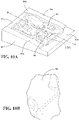
Figure 10B is an enlarged perspective view of a hole in the lid fromFigure 10A ; -
Figure 11A is a perspective view of the lid inFigure 10A with bushings; -
Figure 11B is a perspective enlarged view of a bushing fromFigure 11A ; -
Figure 11C is a cross-sectional view of the bushing fromFigure 11B ; -
Figure 12A is a perspective view of a moving plate of the tool fromFigure 8 ; -
Figure 12B is partial enlarge perspective view of a top end of a clamping pin fromFigure 12A ; -
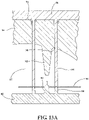
Figure 13A is a partial cross-sectional view of the tool inFigure 8 , with the mat secured inside the tool; -
Figure 13B is a perspective view of the tool inFigure 8 , with the mat secured inside the tool; -
Figure 14A is a side view of the tool fromFigure 8 , showing the lid of the tool in a closed position and the plate engaged with the lid; -
Figure 14B is a side view of the tool fromFigure 8 , showing the lid in the closed position and the moving plate disengaged from the bowl; and -
Figure 14C is a side view of the tool fromFigure 8 , showing the lid in an open position. - Similar reference numerals may have been used in different figures to denote similar components.
-
Figure 1 illustrates aseat 10. Theseat 10 may be a front seat or a rear seat of an automobile or other motor vehicle. Theseat 10 includes aseat cushion 20 and a seat back 30. Thecushion 20 may include a foam pad, such as a thermally conductive foam pad. A portion of the foam pad may be filled with conductive substances, such as electrically conductive substances or thermally conductive substances. Examples of such foam pads are disclosed in provisional application Nos.62/269,526 62/331,518 62/475,956 - In some examples, the
seat cushion 20 may contain a permittivity sensor and an electrically conductive foam pad for sensing the weight of an occupant of theseat 10 and weight distribution of the occupant on theseat cushion 20. The sensed weight may be used to classify the occupant according to the Federal Motor Vehicle Safety Standard 208 (FMVSS 208), which regulates automotive occupant crash protection in the United States, and to identify position changes of the occupant on theseat cushion 20 over time. - In this regard,
Figure 2 illustrates an exemplary construction of aseat cushion 20a. Theseat cushion 20a includes a polyurethane (PU)foam pad 22, apressure sensing system 24 placed on top of thePU foam pad 22 and aPU foam slab 30 placed on top of thepressure sensing system 24. In some examples, thepressure sensing system 24 may be a permittivity sensor. - In the example shown in
Figure 2 , thepressure sensing system 24 includes a flexible printedcircuit 26 and a layer of an electricallyconductive foam 28. The flexible printedcircuit 26 may be a polyethylene terephthalate (PET) or polyimide (PI) flexible printed circuit. The electricallyconductive foam 28 may be Vermafoam™. As illustrated inFigure 3 , the electricallyconductive foam 28 is placed on top of the flexible printedcircuit 26. The electricallyconductive foam 28 is operatively connected with the flexible printedcircuit 26. The electricallyconductive foam 28 may cover the entire area of the flexible printedcircuit 26. The flexible printedcircuit 26 is placed on and supported by thePU foam pad 30. The polyurethane (PU)foam pad 22, thePU foam slab 30, and the electricallyconductive foam 28 mitigate the mechanical stress on the flexible printedcircuit 26 when an occupant sits on theseat cushion 20a. -
Figures 4A and4B illustrate two pressure sensing systems that may be used in aseat 10. Thepressure sensing system 24 inFigure 4A further includes anelectronic control unit 40. Theelectronic control unit 40 may be separated from thepressure sensing system 24 for receiving and processing the sensed data from the flexible printedcircuit 26. - The
pressure sensing system 24 generates in real time the sensed data of the pressure applied on the electricallyconductive foam 28. When an occupant sits on theseat cushion 20 that includes thepressure sensing system 24 ofFigure 4A , the weight of an occupant of theseat 10 may be measured by the pressure created by the occupant on the electricallyconductive foam 28. - The
electronic control unit 40 receives and processes in real time the sensed data for determining the weight of the occupant and the weight distribution of the occupant over theseat cushion 20a. Theelectronic control unit 40 may include a receivingcircuit 41, aprocessor 42 and amemory 44. The receivingcircuit 41 may be an interface circuit, such as a connector, of theelectronic control unit 40 for receiving the sensed data from the output circuit of the flexible printedcircuit 26. The receivingcircuit 41 receives the sensed data output from the flexible printedcircuit 26 and transmits the sensed data to theprocessor 42 for processing or to thememory 44 for storing. Theprocessor 42 may be a central processing unit (CPU). Thememory 44 may include a volatile or non-volatile memory (e.g., a flash memory, a random-access memory (RAM), and/or a read-only memory (ROM)). Theelectronic control unit 40 may be inserted in theseat cushion 20a. - As described above in
Figure 3 , thepressure sensing system 24 includes a layer of electricallyconductive foam 28 and a flexible printedcircuit 26 placed under the electricallyconductive foam 28. For clarity, the electricallyconductive foam 28 is removed inFigure 4A and4B to clearly illustrate the structure of the flexible printedcircuit 26. - In the example shown in
Figure 4A , the flexible printedcircuit 26 has aflexible substrate 26a, a pluralityhorizontal sensing wires 26b and a plurality ofvertical sensing wires 26c securely placed on the top surface of thesubstrate 26a. Theflexible substrate 26a may be a PET or PI substrate. Thesubstrate 26a may have any desired profile. For example, the profile of thesubstrate 26a substantially corresponds to the surface profile of theseat cushion 20 of an automotive seat. - The
sensing wires conductive foam 28 covered on thesensing wires sensing wires sensing wires conductive foam 28. Thehorizontal sensing wires 26b intersect with thevertical sensing wires 26c at a plurality of intersections. At each intersection, avertical sensing wire 26c is electrically connected with ahorizontal sensing wire 26b. In an area of thesubstrate 26a, M horizontal sensing wires intersect with N vertical sensing wires, and (N x M) intersections are created in the area. The area may be the entire surface area or a portion of the entire surface area of theseat cushion 20a. - The
pressure sensing system 24 creates an electric field in the areas surrounding the flexible printedcircuit 26. When an occupant sits on theseat cushion 20a, the weight of the occupant applies pressure to theseat cushion 20a. The pressure is transmitted from thePU foam slab 30 to the electricallyconductive foam layer 28. In response, the electricallyconductive foam layer 28 is deformed or compressed. Different points of the layer of electricallyconductive foam 28 may be subject to different pressures. Accordingly, each point of the layer of electricallyconductive foam 28 may be deformed or compressed to a degree in proportion to the pressure applied to the point. As a result, the electrical properties, such as electrical conductivity and permittivity, of each point of the electricallyconductive foam 28 are changed in the direction of the compression. The changes in the electrical properties at a point in turn change the electric flux density, and thus change the electric field around the point. The (N x M) intersections on the flexible printedcircuit 26 correspond to (N x M) points on the electricallyconductive foam 28. Each intersection generates in real time a sensed electric flux density value ("the sensed data") to reflect the change of the electric flux density and the electric field around the intersection. Each value corresponds to the pressure applied to a corresponding point of the electricallyconductive foam 28. For example, in an area of the flexible printedcircuit 26, fivehorizontal sensing wires 26b and tenvertical sensing wires 26c create 50 intersections distributed over the area. When the electricallyconductive foam 28 in the area is pressed, 50 sensed electric flux density values at the 50 intersections are generated in the area. In other words, the pressure applied to 50 points of theseat cushion 20a is sensed in real time. As such, the degree of changes in the electric flux density and the electric field in the area of the flexible printedcircuit 26 reflects the real time weight of the occupant and the real time weight distribution of the occupant in the area. If the area is the entire surface area of theseat cushion 20, the weight of the occupant in the area represents the total weight of the occupant applied to the seat. The changes of the weight distribution of the occupant in an area over time reflects sitting position changes of the occupant over time. - As such, the electrically
conductive foam 28 and the flexible printedcircuit 26 together form a permittivity sensor for thepressure sensing system 24 to sense the changes of the permittivity of the electricallyconductive foam 28 at the points corresponding to the intersections of the horizontal sensing wires and the vertical sensing wires. - By using the sensing array created by the
horizontal wires 26b and thevertical wires 26c to sense the degree of compression of the electricallyconductive foam 28, each intersection of the sensing wires serves as a pressure sensing unit of the point. Compared with existing pressure sensing technologies with physical sensors, the sensing resolution of thepressure sensing system 24 is improved in that more sensing units may be created at a selected area by the interactions of the sensing wires. The morehorizontal wires 26b and thevertical wires 26c are used in an area, the more intersections and thus more sensing units are created. As such, higher sensing resolution of thepressure sensing system 24 can be achieved. Additionally, a larger area may be sensed by extending the sensing wires to the areas without substantially increasing the cost. - The sensed data from each intersection is output to the
electronic control unit 40 via anoutput wire 39. An end of the output wire is connected to the intersection and the other end of the output wire extends out from thesubstrate 26a, for example about 160 mm, to form a "tail" for mounting on a connector, such as the receivingcircuit 41 of theelectronic control unit 40. Theprocessor 42 may then determine a weight group associated with the occupant according to the sensed (N x M) electric flux density values, for example, by comparing the sensed values with the standard electric flux density values associated with different weight groups. - In some examples, the
memory 44 of thecontrol unit 40 stores a plurality of predetermined use cases U with respect to a specific seat cushion, such asseat cushion 20a, and with respect to a plurality of selected weight groups. The use cases may be generated by theprocessor 42. A use case U may be a matrix having (N x M) elements of standard electric flux density value at each intersection of thehorizontal sensing wires 26b andvertical sensing wires 26c of thepressure sensing system 24 assembled in a specific cushion in a selected area. A use case is associated with a specific seat cushion and a selected weight group. The weight group may be selected according to the classification of FMVSS 208. For example, at a selected area of a selected seat cushion, an occupant weighing 30 kilograms (kg) is associated with a first use case, and an occupant weighing 60 kg is associated a second use case. Different weight groups in a selected area of a specific seat cushion have different use cases. If a seat cushion includes several areas, the same weight group may have different use cases in different areas of a specific seat cushion. - The
processor 42 compares the sensed data with the use cases U to determine the weight group to which an occupant belongs. In some examples, theprocessor 42 stores the sensed data over time in the memory. The stored sensed data may be used, for example, to determine the changes of position of the occupant on the seat cushion over time. - In some examples, as illustrated in
Figure 5 , for an area of the flexible printedcircuit 26 with Nhorizontal sensing wires 26b and Mvertical sensing wires 26c, theprocessor 42 is configured to receive, from the receivingcircuit 41, sensed data from each of the intersection of the sensing wires of the pressure sensing system 24 (step 62) and to arrange the received data in an algebraic matrix S of N rows and M columns (step 64). In some examples, theprocessor 42 receives sensed data from each of the intersection of the sensing wires at a predetermined rate, such as at every 10-60 milliseconds. Each data of the matrix corresponds to a predetermined position of theseat cushion 20a. Accordingly, the use cases U are also arranged in a matrix U having the same dimensions as matrix S, such as N rows and M columns. The element snm of the matrix S and the element unm of the matrix U correspond to the same position of theseat cushion 20a. For example, s11 of the matrix S and the element u11 of the matrix U both refer to the position where the horizontal sensing wire 1 intersects with the vertical sensing wire 1 on theseat cushion 20a. In the example shown inFigure 4A , the flexible printedcircuit 26 or theseat cushion 20a contains five matrixes in five selected areas A, B, C, D, and E. In an example inFigure 7A , the width area A is about 300mm-320mm, the length from the outer edge of area A to the outer edge of area B is about 500mm, and the length from the outer edge of area A to the outer edge of area C is about 780mm. - The
processor 42 may read and compare the matrix Snm with each of the use cases U stored in thememory 44 for an area of theseat cushion 20a (step 66). The use case U of the occupant is then determined based the comparison results of the matrix Snm and the use cases U (step 68). For example, the use case U having the minimum error or minimum difference with the matrix S generated from the sensed data is the selected use case of the occupant. The minimum error or difference may be the minimum standard deviation between the data of the matrix Snm and the data of the use cases Unm. The weight associated with the selected use case U is then used as the weight of the occupant, such as 60 kg. Theprocessor 42 may then send a message to the occupant restraint controller (step 70), for example at a predetermined rate, for the occupant restraint controller to control the deployment of the air bag. The message may be the weight of the occupant derived from the selected use case U. - The weight group to which the occupant belongs may change if an occupant sits out of the position over time. In this case, the
processor 42 may select the maximum weight of the selected weight groups of the occupant as the weight of occupant and send the message including the maximum weight. As such, the sensing system improves the reliability of the sensed weight of the occupant. - The sensing system in
Figure 4B is the same as that inFigure 4A described above, except the differences in the geometry of the flexible printedcircuit 26 and in the number of matrixes or areas contained in the flexible printedcircuit 26. The flexible printedcircuit 26 inFigure 4B contains two matrixes in areas F and G. -
Figure 6 illustrates another exemplary construction of aseat cushion 20b. InFigure 6 , theseat cushion 20b includes a polyurethane (PU)foam pad 22 and apressure sensing system 24 placed on top of thePU foam pad 22. Unlike theseat cushion 20a, theseat cushion 20b does not include aPU foam slab 30. In the example shown inFigure 6 , thepressure sensing system 24 in theseat cushion 20b includes a layer of an electricallyconductive foam 28 and a flexible printedcircuit 26, same as that in theseat cushion 20a. The arrangement of the polyurethane (PU)foam pad 22 and thepressure sensing system 24 are the same as described inseat cushion 20a. - In the example shown in
Figure 6 , as thePU foam slab 30 inseat cushion 20a is not present, the layer of the electricallyconductive foam 28 inseat cushion 20b may be thicker than that in theseat cushion 20a to sufficiently reduce the mechanical stress to the flexible printedcircuit 26. Unlikeseat cushion 20a, when an occupant is seated on theseat cushion 20b, the pressure to theseat cushion 20b applied by the weight of the occupant is directly transmitted to the layer of the electricallyconductive foam 28. As the occupant is directly seated on the surface of the layer of the electricallyconductive foam 28 of theseat cushion 20b, the sensitivity of thepressure sensing system 24 may be improved, in that the degree of the compression of the layer of the electricallyconductive foam 28 may be greater than that of the layer of the electricallyconductive foam 28 inseat cushion 20a. As a result, the changes in the electric flux density and the electric field in the areas surrounding the flexible printedcircuit 26 may become more apparent. - For the same occupant using
seat cushion seat cushion 20a may be different from the use cases U for theseat cushion 20b. - The seat cushions 20a and 20b in the examples of
Figures 2 and 6 are A-surface occupant classification systems. The flexible printedcircuit 26 is assembled in different layers of theseat cushion 20. The layers of theseat cushion 20 and the assembled flexible printedcircuit 26 are encapsulated by a thermoplastic polyurethane elastomer (TPU) sealing cover. Since the flexible printedcircuit 26 is a separate layer from the foam layers, when an occupant sits on theseat cushion 20, the pressure on the seat cushion may cause relative movement between the flexible printedcircuit 26 and other foam layers. As such, the flexible printedcircuit 26 may be abraded by adjacent foam layers. Therefore, the flexible printedcircuit 26 assembled inseat cushion seat 10 may lose pressure sensing function. - In some examples, the
pressure sensing system 24 and other sensors may be insert-molded in a cushion foam, for example the electricallyconductive foam 28, to mitigate the risk of mechanical stresses, creasing, and excessive aging.Figure 7A and7B illustrate twoexemplary sensors - The
sensor 72 may be thepressure sensing system 24 described above. In the exampleFigure 7A , the printed flexible circuit of thesensor 72 has no voids. The sensing portion on the bolsters 72a and 72b may be omitted. The output portion ofsensor 72 extends outside from the cushion foam as a "tail" for mounting on the electrical connectors to output the sensed data. The connectors may be Zero insertion force (ZIF) connectors. The output portion may have a width about 70mm and a length about 160 mm. In addition to the PET flexible printed circuit, thesensor 72 may have a layer of Vermafoam™ on top of the PET flexible printed circuit. - In the example
Figure 7B , thesensor 74 may have the same width, but may have different lengths, such as 780mm or 500mm. The output portion ofsensor 74 extends outside from the cushion foam as a "tail" for mounting on the electrical connectors to output the sensed data. In some examples, the output portion may have a width about 70mm and a length about 160 mm. The mat ofsensor 74 may be cut using a die and the space in between each sensing unit 76 is about 30mm x 20mm. In some examples, the edges of the mat are shortened to under 5mm. -
Figures 8-14c illustrate an exemplary insert-molding tool 80 for injecting a mat, such as a Molex™ mat, inside acushion foam 100. The mat includes thesensors 72 inFigure 7A and 74 inFigure 7B , or sensors formed by any flexible printedcircuit 26. - In the example shown in
Figure 8 , thetool 80 includes abowl 82, alid 84 and a movingplate 86. Aspace 87 is formed between thelid 84 and thebowl 82 when thelid 84 is closed on thebowl 82. The profile of thespace 87 forms the profile of thecushion foam 100. The profile of thespace 87 may be varied according to the profile of thecushion foam 100. The relative positions of "top" and "bottom" referred to below are with respect to the normal use position oftool 80, namely that thelid 84 covers thebowl 82, and the movingplate 86 engages thelid 84. - As shown in
Figure 9A , thebowl 82 has a substantially rectangular body portion and fourside walls bowl 82. Theside wall 82a is higher than theopposed side wall 82b, and theside walls side walls side walls side wall 82b to the end connected to theside wall 82a. In the example shown inFigure 9A , theside wall 82b has aprotrusion 83 at the central portion of the top surface of theside wall 82b; the height of the end portion of theside walls side wall 82a is substantially the same as the height of theside wall 82a. - The bottom surface of the
bowl 82 is substantially flat but may include different patterns, such as grooves or protrusions, to form desired patterns on the top surface of a cushion foam. - In
Figure 9A , thebowl 82 includes a plurality ofpins 88 on the bottom surface of the body portion for securely receiving amat 98, such as a Molex™ mat, such assensors bowl 82. In an example, thebowl 82 has 15pins 88. As illustrated inFigure 9B , thepin 88 includes abase 88a, such as a conical cylinder base, extending from the bottom surface of thebowl 82 and atop portion 88b, such as a top cylinder, extending from the top surface of thebase 88a. In an example shown inFigure 9B , thebase 88a has a height of 15mm from the bottom surface of thebowl 82 to the top surface of thebase 88a, and top surface of thebase 88a has a diameter of 6mm; thetop portion 88b has a diameter of 3mm and a height of 2mm from the top surface of thebase 88a to the top surface of thetop portion 88b. In the example shown in thesensor circuit 26 has a plurality of through holes in the "dead zones" of the flexible printedcircuit 26. The "dead zones" are areas on the flexible printedcircuit 26 without any conductive traces or wires. The flexible printedcircuit 26 is placed on thepins 88 via the holes in the "dead zones". As such, positions of the sensor units 76 ofsensor 72 or positions of the wire intersections ofsensor 24 are fixed in relation to the positons of thepins 88. Sensors including flexible printed circuits with different geometries may also be placed around thetop portion 88b and on the top surface of thebase 88a, as long as the positions of the sensing units associated with the flexible printed circuit are fixed in relation to the top surface of thebowl 82. In other words, the positions of the sensing units associated with the flexible printed circuit are fixed on the top surface of a seat cushion. As such, use cases Ui for one seat cushion manufactured with thetool 80 may be used in all of the seat cushion manufactured by the same tool. -
Figure 10A illustrates anexemplary lid 84. Thelid 84 has a body portion and fourside walls lid 84. Theside wall 84a is lower than theopposed side wall 84b, and theside walls side walls side walls side wall 84b to the end connected to theside wall 84a. In the example shown inFigure 10A , theside wall 84b has agroove 85 at the central portion of the top surface of theside wall 84b to receive theprotrusion 83 of thebowl 82; the height of the end portion of theside walls side wall 84a is substantially the same as the height of theside wall 84a. As such, when thelid 84 is closed on thebowl 82, the top surfaces ofside walls bowl 82 engage the respective top surfaces ofside walls lid 84 to form a liquid leakage-proof space 87 between the bottom surface of the body portion of thebowl 82 and the top surface of the body portion of thelid 84. - In the example shown in
Figure 10A , the top surface of the body portion of thelid 82 has a profile for producing the profile of the bottom surface of a seat cushion when a liquid foam is injected into thespace 87. The top surface of thelid 82 may include different patterns, such as grooves orprotrusions 99, to form desired patterns on the bottom surface of thecushion foam 100. - The top surface of the body portion of the
lid 84 includes a plurality of throughholes 90 and a plurality ofconical cylinders 92 protruded for the bottom surface of the body portion oflid 84 toward thebowl 82. The through holes 90 may be cylinder through holes. The size of theconical cylinders 92 from the top surface of the body portion of thelid 84 to the end surface of theconical cylinders 92 may be varied. Each of the throughholes 90 penetrates through the bottom surface and top surface of the body portion oflid 84. Thelid 84 may have the same number of the throughholes 90 as the number of thepins 88 of thebowl 82. Each throughholes 90 corresponds to apin 88 on the bottom surface of the body portion of thebowl 82. In the example shown inFigure 10B , the throughhole 90 has a radius of 3.1mm. Theconical cylinders 92 provide trenches in the bottom of thecushion foam 100 to allow assembly and attachment of a trim cover (not shown) via hog-rings, as is well known in the seating industry. - In the example shown in
Figure 11A , each of the throughholes 90 may include abushing 96 inserted in the opening of the throughholes 90 on the top surface of the body of thelid 82. Thebushing 96 guides and cleans the clamping pins of the movingplate 86 as described below. In the example shown inFigure 11C , thebushing 96 has an inner diameter about 6mm between the inner side of the walls of the bushing, an outer diameter about 10mm between the outer side of the walls of the bottom portion of the bushing, and a length about 10mm from the bottom surface to the top surface of the bushing. The diameter is about 13mm between the outer side of the walls of the top portion of thebushing 96. -
Figure 12A is an exemplary movingplate 86. The movingplate 86, also known as a pin tower, includes aplate base 86a and a plurality of clampingpins 94 extended downwardly from the bottom surface of theplate base 86a. Theplate base 86a may be a rectangular plate. In some examples, the clamping pins 94 may be elongated cylinders. As illustrated inFigure 12B , the central portion of the top end of the clampingpin 94 has acylindrical recess 94a for removably engaging thetop portion 88b of thepin 88 on thebowl 82 to retain a mat, such as a Molex™ mat, between thepin 88 and the clampingpin 94. In one example, the depth of thecylindrical recess 94a is about 0.5mm. - The clamping pins 94 are configured to penetrate through the corresponding through
holes 90 on the body portion of thelid 84 and to engage the corresponding pins 88 of thebowl 82 when the bottom surface of theplate base 86a is placed on the top surface of thelid 84 and when thelid 84 is closed on thebowl 82. In the examples ofFigures 13A and13B , thelid 84 is closed on thebowl 82, and the clamping pins 94 of themovable plate 86 penetrate, via thebushings 96, the throughholes 90 and clamp themat 98, such as a Molex™ mat, on thepins 88 by engaging thetop portion 88b of thepins 88 with thecylindrical recess 94a of the clamping pins 94. This position is referred herein as the "closed position" of thetool 80. For example, 15 clamping pins 94 of themovable plate 86 penetrate, via the corresponding respective 15bushings 96, the corresponding respective 15 throughholes 90 and clamp themat 98, such as a Molex™ mat, on the corresponding respective 15pins 88 by engaging the 15top portions 88b of thepins 88 with the corresponding respective 15 thecylindrical recesses 94a of the clamping pins 94. As such, themat 98 is securely retained at a predetermined position between the clamping pins 94 and thepins 88 inspace 87 inside thetool 80. Thetool 80 in a closed position is liquid leakage-proof. - The
conical cylinder 92 on thelid 84 downwardly faces theprotrusion 99 of thebowl 82. Theconical cylinders 92 provide trenches in the bottom of thecushion foam 100 while theprotrusions 99 provide trenches in the top of thecushion foam 100 to allow assembly and attachment of a trim cover (not shown) via hog-rings, as is well known in the seating industry. - The shape and dimensions of the
bowl 82, thelid 84, and the movingplate 86, including thepin 88, the throughhole 90, and the clamping pins 94, may be varied so long as when thelid 84 is closed on bowl 82 (i) thebowl 82 and thelid 84 form aspace 87 for forming acushion foam 100 with desired profile; (ii) themat 98 is fixed at a predetermined position at a predetermined height above the top surface of thebowl 82, and (iii) thebowl 82 andlid 84 form a liquid leakage-proof space 87. - When the
tool 80 is closed, the output end 81 (Figure 8 ) of thesensor circuit 26, extends outside thetool 80 between the top surface of theside wall 82b of the bowl and bottom surface of theside wall 84b of thelid 84. When manufacturing a cushion pad, the liquid cushion foam, such as liquid PU foam and/or liquid electrically conductive foam, may be injected, such as via a nozzle, into thespace 87 and onto and around themat 98, such as a Molex™ mat. The liquid foam injected inside thespace 87 cannot leak outside thetool 80 when thetool 87 is in a closed position. The injected liquid foam generally expands within thespace 87 in five to ten seconds after the liquid foam is injected in thetool 80. The expanded foam is then cured in thetool 80. Air within thetool space 87 is vented out of the tool as the liquid foam expands and cures, as is commonly known in the foaming industry. - After the
cushion foam 100 is fully cured, themat 98 is now insert-molded inside thecushion foam 100.Figures 14A -14C illustrate the process of removing the curedcushion foam 100 from thetool 80. InFigure 14A , thetool 80 remains in the closed position until thecushion foam 100 is expanded and fully cured in thespace 87. To remove the curedcushion foam 100 from thetool 80, in the example shown inFigure 14B , the movingplate 86 is pulled up, for example, for about 98mm, from the top surface of thelid 84 to allow the clamping pins 94 to fully disengage the B-side of thecushion foam 100. As illustrated inFigure 14C , thelid 84 can then be opened up from thebowl 82, and thecushion foam 100 may then be removed from thebowl 82 with themat 98 molded inside theseat cushion foam 100. - Because the
mat 98 is insert-molded inside theseat cushion foam 100 to form an integrated part, when an occupant sits on theseat cushion foam 100, relative movement between the flexible printedcircuit 26 and other foam layers, or abrasion between the flexible printedcircuit 26 and the surrounding foam, is eliminated or substantially reduced. Therefore, mechanical stresses, creasing, and excessive aging of the flexible printedcircuit 26 is reduced. - Certain adaptations and modifications of the described embodiments can be made as long as the resulting embodiments belong to one of the scope defined by the appended claims. Therefore, the above discussed embodiments are considered to be illustrative and not restrictive.
Claims (15)
- A pressure sensing system (24) for a seat cushion (20), comprising:
a flexible printed circuit (26) comprising:a flexible substrate (26a); andN horizontal sensing wires (26b) and M vertical sensing wires (26c) securely placed on a top surface of the flexible substrate (26a), wherein the horizontal sensing wires (26b) intersect with the vertical sensing wires (26c) and form (NXM) intersections; anda layer of an electrically conductive foam (28) placed on top of the N horizontal sensing wires (26b) and the M vertical sensing wires (26c),wherein when a pressure is applied to the layer of the electrically conductive foam (28), each intersection generates in real time an electric flux density value to reflect a degree of a compression caused by the pressure to a corresponding point of the electrically conductive foam (28). - The pressure sensing system (24) of claim 1, further comprising an electronic control unit (40) for receiving and processing the electric flux density value from each intersection of the flexible printed circuit (26).
- The pressure sensing system (24) of claim 2, wherein the electronic control unit (40) includes a receiving circuit (41) for receiving the electric flux density value generated from the each intersection of the flexible printed circuit (26).
- The pressure sensing system (24) of claim 3, wherein the electronic control unit (40) includes a processor (42) for processing the electric flux density value from each intersection of the flexible printed circuit (26).
- The pressure sensing system (24) of claim 4, wherein the processor (42) is configured to generate a matrix SNM comprising the electric flux density value from each intersection of the flexible printed circuit (26).
- The pressure sensing system (24) of claim 4, wherein the electronic control unit (40) includes a memory (44) for storing use cases and the electric flux density value from each intersection of the flexible printed circuit (26), wherein the processor (42) is preferably configured to compare the matrix SNM with a plurality of use cases to derive a weight group associated with the pressure.
- The pressure sensing system (24) of claim 1, wherein the flexible substrate (26a) is a polyethylene terephthalate (PET) or polyimide (PI) flexible substrate (26a); and/or wherein the compression causes a change in the permittivity of the layer of the electrically conductive foam (28) around the corresponding point of the electrically conductive foam (28).
- A seat cushion (20) comprising:a polyurethane (PU) foam pad (22),
the pressure sensing system (24) of any one of claims 1 to 7 placed on top of the PU foam pad (22),wherein the pressure is applied when an occupant sits on the seat cushion (20). - The seat cushion (20) of claim 8, further comprising an electronic control unit (40) configured to receive the electric flux density value from each intersection of the flexible printed circuit (26) and to derive a weight group of the occupant; and/orfurther comprising a PU foam slab (30) placed on top of the layer of the electrically conductive foam (28); and/orwherein the flexible printed circuit (26) is between the polyurethane (PU) foam pad (22) and the layer of the electrically conductive foam (28); and/orwherein the flexible printed circuit (26) is insert-molded inside the polyurethane (PU) foam pad (22) or the layer of the electrically conductive foam (28); and/orwherein the seat cushion (20) is an automotive seat cushion.
- A method for sensing a weight group associated with an occupant of an automotive seat comprising:receiving, by a processor (42), (NXM) electric flux density values from (NXM) intersections formed by N horizontal sensing wires (26b) and M vertical sensing wires (26c) of a flexible substrate (26a) placed on the automotive seat, each electric flux density value reflecting a degree of compression caused by a pressure to a corresponding point of an electrically conductive foam (28) placed on the flexible substrate (26a);determining, by the processor (42), a weight group associated with the occupant according to the (NXM) electric flux density values; andsending, by the processor (42), the weight group associated with the occupant to an occupant restraint controller.
- The method of claim 10, wherein determining the weight group comprises:generating a plurality of use cases of the automotive seat, such that each user case is a matrix Unm based on the (NXM) standard electric flux density values associated with a standard weight group at (NXM) intersections;generating a matrix Snm based on the (NXM) electric flux density values;comparing the matrix Snm with the plurality of use cases; anddetermining the weight group associated with a selected use case as the weight group of the occupant;wherein preferably the selected use case has a minimum error with respect the matrix Snm; and/orwherein preferably the standard weight group is selected according to Federal Motor Vehicle Safety Standard 208.
- An insert-molding tool for manufacturing a seat cushion (20), comprising:a bowl (82) having a body portion and a first plurality of side walls (82a, 82b, 82c, 82d);a plurality of pins (88) on a top surface of the body portion of the bowl (82) for securely receiving a mat (98);a lid (84) having a body portion and a second plurality of side walls (84a, 84b, 84c, 84d), the body portion of the lid having a plurality of through holes (90); anda moving plate (86) having a plate base (86a) and a plurality of clamping pins (94) extended downwardly from a bottom surface of the plate base (86a), wherein the plurality of clamping pins (94) is configured to penetrate through the corresponding through holes (90) and to engage the corresponding pins (88) of the bowl (82), and wherein when a bottom surface of the plate base (86a) is placed on a top surface of the lid (84) such that the lid (84) engages the bowl (82) to form a liquid leakage-proof space (87) .
- The insert-molding tool of claim 12, wherein each of the pins (88) includes a base (88a) extending from the top surface of the bowl (82) and a top portion (88b) extending from the top surface of the base (88a); and/orwherein the bowl (82) has 15 pins (88), the lid has 15 through holes (90), and the moving plate (86) has 15 clamping pin (94)s; and/orwherein each of the through holes (90) includes a bush (96) .
- A method for insert-molding a mat (98) inside a seat cushion foam using the insert-molding tool of claims 12 or 13, the method comprising:securely placing the mat (98) at a predetermined position and at a predetermined height above the top surface of the bowl (82);forming a liquid leakage-proof space (87) between the top surface of the bowl (82) and the lid (84) such that the mat (98) is orientated within the space (87); andinjecting liquid foam into the space (87).
- The method of claim 14, wherein securely placing the mat (98) comprises clamping the mat (98) inside the space (87), preferably comprising clamping the mat (98) between pins (88) extended upwardly from the bowl (82) and clamping pins (94) extended downwardly from a moving plate (86) that engages the lid (84); and/or
wherein the mat (98) comprises sensors including a flexible printed circuit (26).
Applications Claiming Priority (2)
| Application Number | Priority Date | Filing Date | Title |
|---|---|---|---|
| US201762529517P | 2017-07-07 | 2017-07-07 | |
| PCT/US2018/041188 WO2019010473A1 (en) | 2017-07-07 | 2018-07-09 | Pressure sensing system and seat cushion having the pressure sensing system |
Publications (2)
| Publication Number | Publication Date |
|---|---|
| EP3649009A1 EP3649009A1 (en) | 2020-05-13 |
| EP3649009B1 true EP3649009B1 (en) | 2022-11-02 |
Family
ID=63036406
Family Applications (1)
| Application Number | Title | Priority Date | Filing Date |
|---|---|---|---|
| EP18746431.8A Active EP3649009B1 (en) | 2017-07-07 | 2018-07-09 | Pressure sensing system and seat cushion having the pressure sensing system |
Country Status (4)
| Country | Link |
|---|---|
| US (3) | US12083989B2 (en) |
| EP (1) | EP3649009B1 (en) |
| CN (1) | CN110869239B (en) |
| WO (1) | WO2019010473A1 (en) |
Families Citing this family (11)
| Publication number | Priority date | Publication date | Assignee | Title |
|---|---|---|---|---|
| WO2019090048A1 (en) * | 2017-11-03 | 2019-05-09 | Magna Seating Inc. | Electrically conductive urethane foam |
| KR102588072B1 (en) * | 2018-08-27 | 2023-10-12 | 삼성전자주식회사 | Method for manufacturing an insole |
| KR102514651B1 (en) | 2018-08-27 | 2023-03-28 | 삼성전자주식회사 | Insole and shoes comprising the same |
| KR102604085B1 (en) | 2018-12-12 | 2023-11-21 | 삼성전자주식회사 | Shoe type apparatus and control method thereof |
| DE102019203979A1 (en) | 2019-03-22 | 2020-09-24 | Greiner Aerospace Gmbh | Seat cushion for an aircraft seat with integrated sensor electronics |
| WO2021134008A1 (en) | 2019-12-24 | 2021-07-01 | Joyson Safety Systems Acquisition Llc | Apparatus and method of producing a sensing substrate |
| WO2022221416A1 (en) * | 2021-04-14 | 2022-10-20 | Adient Us Llc | Article with integrally formed features |
| CN114993526B (en) * | 2022-05-05 | 2025-06-10 | 上海润势科技有限公司 | A pressure sensor and electronic device capable of realizing multi-directional sensing |
| CN117048468A (en) * | 2023-08-31 | 2023-11-14 | 广东安闻汽车零部件有限公司 | Seat foam and seat |
| FR3162400A1 (en) * | 2024-05-27 | 2025-11-28 | Faurecia Sièges d'Automobile | Method for determining the height and weight type of a seat occupant |
| US12399294B1 (en) | 2024-09-24 | 2025-08-26 | Studio 1 Labs Inc. | Projected dielectric sensor for matter detection, proximity detection, and gesture control |
Family Cites Families (29)
| Publication number | Priority date | Publication date | Assignee | Title |
|---|---|---|---|---|
| US5060527A (en) * | 1990-02-14 | 1991-10-29 | Burgess Lester E | Tactile sensing transducer |
| US6738697B2 (en) * | 1995-06-07 | 2004-05-18 | Automotive Technologies International Inc. | Telematics system for vehicle diagnostics |
| JP2708084B2 (en) | 1992-03-23 | 1998-02-04 | ワイケイケイ株式会社 | Method of attaching hook-and-loop fastener to seat cushion material and foam molding die |
| US20050192727A1 (en) * | 1994-05-09 | 2005-09-01 | Automotive Technologies International Inc. | Sensor Assemblies |
| US7103460B1 (en) * | 1994-05-09 | 2006-09-05 | Automotive Technologies International, Inc. | System and method for vehicle diagnostics |
| US7421321B2 (en) * | 1995-06-07 | 2008-09-02 | Automotive Technologies International, Inc. | System for obtaining vehicular information |
| JP3389775B2 (en) * | 1995-05-19 | 2003-03-24 | 株式会社デンソー | Insert product molding method and insert product molding device |
| JP3775376B2 (en) * | 1995-05-19 | 2006-05-17 | 株式会社デンソー | Insert product molding method and insert product molding apparatus |
| US5878620A (en) * | 1997-01-23 | 1999-03-09 | Schlege Systems, Inc. | Conductive fabric sensor for vehicle seats |
| SK18562000A3 (en) | 1998-06-03 | 2001-08-06 | Magna Interior Systems Inc. | METHOD FOR DISPLAYING PRESSURE TO DETERMINE THE COMFORT OF THE CAR SEAT |
| US7089099B2 (en) * | 2004-07-30 | 2006-08-08 | Automotive Technologies International, Inc. | Sensor assemblies |
| EP1666859A1 (en) * | 2004-12-03 | 2006-06-07 | IEE INTERNATIONAL ELECTRONICS & ENGINEERING S.A. | Method for manufacturing a sensor mat |
| US7703342B2 (en) * | 2005-03-30 | 2010-04-27 | Xiroku, Inc. | Pressure distribution detection device |
| CN101467015B (en) * | 2006-04-25 | 2011-03-30 | X感应器技术公司 | Capacitive Node Measurements in Capacitive Matrix Pressure Sensors |
| KR101020541B1 (en) * | 2007-11-21 | 2011-03-09 | 기아자동차주식회사 | Vehicle passenger identification device and method |
| KR101054772B1 (en) * | 2008-08-26 | 2011-08-05 | 기아자동차주식회사 | Capacitor Type Sheet Sensor |
| GB2488600B (en) * | 2011-03-04 | 2013-05-29 | Hm Technology Internat Ltd | A force sensor |
| JP5644791B2 (en) * | 2011-10-31 | 2014-12-24 | 住友ベークライト株式会社 | Release film |
| DE102011056371B4 (en) * | 2011-12-13 | 2014-01-09 | abele rößler technologies GmbH | Device for checking conductor structures |
| CA2863197A1 (en) * | 2012-03-08 | 2013-09-12 | Quality Manufacturing Inc. | Touch sensitive robotic gripper |
| US9175571B2 (en) * | 2012-03-19 | 2015-11-03 | General Electric Company | Connecting system for metal components and CMC components, a turbine blade retaining system and a rotating component retaining system |
| JP5979058B2 (en) | 2013-03-29 | 2016-08-24 | トヨタ紡織株式会社 | Vehicle seat |
| WO2015012859A1 (en) * | 2013-07-26 | 2015-01-29 | Tempur-Pedic Management, Llc | Support cushions for providing cooling |
| KR101605344B1 (en) | 2014-06-23 | 2016-03-22 | 주식회사 서연씨엔에프 | manufacturing mold of Seat Pad having different hardnesses and manufacturing method using thereof |
| US9625330B2 (en) * | 2014-08-01 | 2017-04-18 | The Board Of Trustees Of The Leland Stanford Junior University | Methods and apparatus concerning multi-tactile sensitive (E-skin) pressure sensors |
| US10168804B2 (en) * | 2015-09-08 | 2019-01-01 | Apple Inc. | Stylus for electronic devices |
| US11241934B2 (en) * | 2018-12-28 | 2022-02-08 | Intel Corporation | Techniques to optimize vehicular systems for occupant presence and condition |
| KR20230104184A (en) * | 2020-10-28 | 2023-07-07 | 솔라페인트 엘티디. | Injection molded, blow molded and rotationally molded articles incorporating photovoltaic devices in one piece and methods and systems for producing such articles |
| DE112022000814T5 (en) * | 2021-01-27 | 2023-11-16 | Indiana Mills & Manufacturing, Inc. | Electronic harness system |
-
2018
- 2018-07-09 EP EP18746431.8A patent/EP3649009B1/en active Active
- 2018-07-09 WO PCT/US2018/041188 patent/WO2019010473A1/en not_active Ceased
- 2018-07-09 CN CN201880045195.8A patent/CN110869239B/en active Active
- 2018-07-09 US US16/629,179 patent/US12083989B2/en active Active
-
2024
- 2024-08-06 US US18/795,460 patent/US20240391416A1/en active Pending
- 2024-08-06 US US18/795,422 patent/US20240391415A1/en active Pending
Also Published As
| Publication number | Publication date |
|---|---|
| CN110869239A (en) | 2020-03-06 |
| US12083989B2 (en) | 2024-09-10 |
| EP3649009A1 (en) | 2020-05-13 |
| US20210086721A1 (en) | 2021-03-25 |
| CN110869239B (en) | 2022-02-22 |
| CA3069310A1 (en) | 2019-01-10 |
| WO2019010473A1 (en) | 2019-01-10 |
| US20240391416A1 (en) | 2024-11-28 |
| US20240391415A1 (en) | 2024-11-28 |
Similar Documents
| Publication | Publication Date | Title |
|---|---|---|
| US20240391416A1 (en) | Pressure sensing system and seat cushion having the pressure sensing system | |
| EP1299268B1 (en) | Hardware independent mapping of multiple sensor configurations for classification of persons | |
| US20150283923A1 (en) | Seat occupancy sensor unit at a lower b-surface side of a seat cushion | |
| US7726207B2 (en) | Pressure sensing mat | |
| US8700265B2 (en) | Occupant classification system | |
| JPH09226428A (en) | Functional mats with electrical contact, especially sensor mats or heating mats | |
| EP1544048A1 (en) | Device for the classification of seat occupancy | |
| EP1631478A1 (en) | Method and apparatus for sensing seat occupancy | |
| US20040263154A1 (en) | Spring sensor assembly for a vehicle seat cushion | |
| EP2842798B1 (en) | Vehicle seat occupant sensor and heater element | |
| US6683534B2 (en) | Vehicle seat occupant detection system with seat cushion identifying transponder | |
| US6650978B1 (en) | Method and apparatus for preserving calibration data in a vehicle seat occupant detection system | |
| WO2014063962A1 (en) | Seat occupancy sensor unit for seat with spring suspension or seat pan | |
| CA3069310C (en) | Pressure sensing system and seat cushion having the pressure sensing system | |
| US9283867B2 (en) | Conveyance seat | |
| US7641229B2 (en) | Seat control structure for occupant classification systems | |
| US7516809B2 (en) | System and method for occupant detection and classification in motor vehicles | |
| US20040012499A1 (en) | Occupant-presence sensing | |
| US7708101B2 (en) | Motor vehicle seat having occupant detector | |
| US11007901B2 (en) | Seat | |
| US20210354595A1 (en) | Sensor carrier to carry one or more sensor elements and cabling | |
| US11850973B2 (en) | Motor vehicle seat | |
| EP1693253A1 (en) | Child seat sensor antenna |
Legal Events
| Date | Code | Title | Description |
|---|---|---|---|
| STAA | Information on the status of an ep patent application or granted ep patent |
Free format text: STATUS: UNKNOWN |
|
| STAA | Information on the status of an ep patent application or granted ep patent |
Free format text: STATUS: THE INTERNATIONAL PUBLICATION HAS BEEN MADE |
|
| PUAI | Public reference made under article 153(3) epc to a published international application that has entered the european phase |
Free format text: ORIGINAL CODE: 0009012 |
|
| STAA | Information on the status of an ep patent application or granted ep patent |
Free format text: STATUS: REQUEST FOR EXAMINATION WAS MADE |
|
| 17P | Request for examination filed |
Effective date: 20191211 |
|
| AK | Designated contracting states |
Kind code of ref document: A1 Designated state(s): AL AT BE BG CH CY CZ DE DK EE ES FI FR GB GR HR HU IE IS IT LI LT LU LV MC MK MT NL NO PL PT RO RS SE SI SK SM TR |
|
| AX | Request for extension of the european patent |
Extension state: BA ME |
|
| DAV | Request for validation of the european patent (deleted) | ||
| DAX | Request for extension of the european patent (deleted) | ||
| STAA | Information on the status of an ep patent application or granted ep patent |
Free format text: STATUS: EXAMINATION IS IN PROGRESS |
|
| 17Q | First examination report despatched |
Effective date: 20201103 |
|
| RIC1 | Information provided on ipc code assigned before grant |
Ipc: G01L 1/20 20060101ALI20220602BHEP Ipc: B29L 31/34 20060101ALI20220602BHEP Ipc: B29K 679/00 20060101ALI20220602BHEP Ipc: B29K 667/00 20060101ALI20220602BHEP Ipc: B29K 75/00 20060101ALI20220602BHEP Ipc: B29C 33/12 20060101ALI20220602BHEP Ipc: G01L 1/14 20060101ALI20220602BHEP Ipc: B29C 44/58 20060101ALI20220602BHEP Ipc: B29C 44/12 20060101ALI20220602BHEP Ipc: B60R 21/015 20060101ALI20220602BHEP Ipc: B60N 2/70 20060101ALI20220602BHEP Ipc: B60N 2/00 20060101AFI20220602BHEP |
|
| GRAP | Despatch of communication of intention to grant a patent |
Free format text: ORIGINAL CODE: EPIDOSNIGR1 |
|
| STAA | Information on the status of an ep patent application or granted ep patent |
Free format text: STATUS: GRANT OF PATENT IS INTENDED |
|
| INTG | Intention to grant announced |
Effective date: 20220712 |
|
| GRAS | Grant fee paid |
Free format text: ORIGINAL CODE: EPIDOSNIGR3 |
|
| GRAA | (expected) grant |
Free format text: ORIGINAL CODE: 0009210 |
|
| STAA | Information on the status of an ep patent application or granted ep patent |
Free format text: STATUS: THE PATENT HAS BEEN GRANTED |
|
| AK | Designated contracting states |
Kind code of ref document: B1 Designated state(s): AL AT BE BG CH CY CZ DE DK EE ES FI FR GB GR HR HU IE IS IT LI LT LU LV MC MK MT NL NO PL PT RO RS SE SI SK SM TR |
|
| REG | Reference to a national code |
Ref country code: GB Ref legal event code: FG4D |
|
| REG | Reference to a national code |
Ref country code: CH Ref legal event code: EP Ref country code: AT Ref legal event code: REF Ref document number: 1528534 Country of ref document: AT Kind code of ref document: T Effective date: 20221115 |
|
| REG | Reference to a national code |
Ref country code: DE Ref legal event code: R096 Ref document number: 602018042558 Country of ref document: DE |
|
| REG | Reference to a national code |
Ref country code: IE Ref legal event code: FG4D |
|
| REG | Reference to a national code |
Ref country code: LT Ref legal event code: MG9D |
|
| REG | Reference to a national code |
Ref country code: NL Ref legal event code: MP Effective date: 20221102 |
|
| REG | Reference to a national code |
Ref country code: AT Ref legal event code: MK05 Ref document number: 1528534 Country of ref document: AT Kind code of ref document: T Effective date: 20221102 |
|
| PG25 | Lapsed in a contracting state [announced via postgrant information from national office to epo] |
Ref country code: SE Free format text: LAPSE BECAUSE OF FAILURE TO SUBMIT A TRANSLATION OF THE DESCRIPTION OR TO PAY THE FEE WITHIN THE PRESCRIBED TIME-LIMIT Effective date: 20221102 Ref country code: PT Free format text: LAPSE BECAUSE OF FAILURE TO SUBMIT A TRANSLATION OF THE DESCRIPTION OR TO PAY THE FEE WITHIN THE PRESCRIBED TIME-LIMIT Effective date: 20230302 Ref country code: NO Free format text: LAPSE BECAUSE OF FAILURE TO SUBMIT A TRANSLATION OF THE DESCRIPTION OR TO PAY THE FEE WITHIN THE PRESCRIBED TIME-LIMIT Effective date: 20230202 Ref country code: LT Free format text: LAPSE BECAUSE OF FAILURE TO SUBMIT A TRANSLATION OF THE DESCRIPTION OR TO PAY THE FEE WITHIN THE PRESCRIBED TIME-LIMIT Effective date: 20221102 Ref country code: FI Free format text: LAPSE BECAUSE OF FAILURE TO SUBMIT A TRANSLATION OF THE DESCRIPTION OR TO PAY THE FEE WITHIN THE PRESCRIBED TIME-LIMIT Effective date: 20221102 Ref country code: ES Free format text: LAPSE BECAUSE OF FAILURE TO SUBMIT A TRANSLATION OF THE DESCRIPTION OR TO PAY THE FEE WITHIN THE PRESCRIBED TIME-LIMIT Effective date: 20221102 Ref country code: AT Free format text: LAPSE BECAUSE OF FAILURE TO SUBMIT A TRANSLATION OF THE DESCRIPTION OR TO PAY THE FEE WITHIN THE PRESCRIBED TIME-LIMIT Effective date: 20221102 |
|
| PG25 | Lapsed in a contracting state [announced via postgrant information from national office to epo] |
Ref country code: RS Free format text: LAPSE BECAUSE OF FAILURE TO SUBMIT A TRANSLATION OF THE DESCRIPTION OR TO PAY THE FEE WITHIN THE PRESCRIBED TIME-LIMIT Effective date: 20221102 Ref country code: PL Free format text: LAPSE BECAUSE OF FAILURE TO SUBMIT A TRANSLATION OF THE DESCRIPTION OR TO PAY THE FEE WITHIN THE PRESCRIBED TIME-LIMIT Effective date: 20221102 Ref country code: LV Free format text: LAPSE BECAUSE OF FAILURE TO SUBMIT A TRANSLATION OF THE DESCRIPTION OR TO PAY THE FEE WITHIN THE PRESCRIBED TIME-LIMIT Effective date: 20221102 Ref country code: IS Free format text: LAPSE BECAUSE OF FAILURE TO SUBMIT A TRANSLATION OF THE DESCRIPTION OR TO PAY THE FEE WITHIN THE PRESCRIBED TIME-LIMIT Effective date: 20230302 Ref country code: HR Free format text: LAPSE BECAUSE OF FAILURE TO SUBMIT A TRANSLATION OF THE DESCRIPTION OR TO PAY THE FEE WITHIN THE PRESCRIBED TIME-LIMIT Effective date: 20221102 Ref country code: GR Free format text: LAPSE BECAUSE OF FAILURE TO SUBMIT A TRANSLATION OF THE DESCRIPTION OR TO PAY THE FEE WITHIN THE PRESCRIBED TIME-LIMIT Effective date: 20230203 |
|
| P01 | Opt-out of the competence of the unified patent court (upc) registered |
Effective date: 20230517 |
|
| PG25 | Lapsed in a contracting state [announced via postgrant information from national office to epo] |
Ref country code: NL Free format text: LAPSE BECAUSE OF FAILURE TO SUBMIT A TRANSLATION OF THE DESCRIPTION OR TO PAY THE FEE WITHIN THE PRESCRIBED TIME-LIMIT Effective date: 20221102 |
|
| PG25 | Lapsed in a contracting state [announced via postgrant information from national office to epo] |
Ref country code: SM Free format text: LAPSE BECAUSE OF FAILURE TO SUBMIT A TRANSLATION OF THE DESCRIPTION OR TO PAY THE FEE WITHIN THE PRESCRIBED TIME-LIMIT Effective date: 20221102 Ref country code: RO Free format text: LAPSE BECAUSE OF FAILURE TO SUBMIT A TRANSLATION OF THE DESCRIPTION OR TO PAY THE FEE WITHIN THE PRESCRIBED TIME-LIMIT Effective date: 20221102 Ref country code: EE Free format text: LAPSE BECAUSE OF FAILURE TO SUBMIT A TRANSLATION OF THE DESCRIPTION OR TO PAY THE FEE WITHIN THE PRESCRIBED TIME-LIMIT Effective date: 20221102 Ref country code: DK Free format text: LAPSE BECAUSE OF FAILURE TO SUBMIT A TRANSLATION OF THE DESCRIPTION OR TO PAY THE FEE WITHIN THE PRESCRIBED TIME-LIMIT Effective date: 20221102 Ref country code: CZ Free format text: LAPSE BECAUSE OF FAILURE TO SUBMIT A TRANSLATION OF THE DESCRIPTION OR TO PAY THE FEE WITHIN THE PRESCRIBED TIME-LIMIT Effective date: 20221102 |
|
| REG | Reference to a national code |
Ref country code: DE Ref legal event code: R097 Ref document number: 602018042558 Country of ref document: DE |
|
| PG25 | Lapsed in a contracting state [announced via postgrant information from national office to epo] |
Ref country code: SK Free format text: LAPSE BECAUSE OF FAILURE TO SUBMIT A TRANSLATION OF THE DESCRIPTION OR TO PAY THE FEE WITHIN THE PRESCRIBED TIME-LIMIT Effective date: 20221102 Ref country code: AL Free format text: LAPSE BECAUSE OF FAILURE TO SUBMIT A TRANSLATION OF THE DESCRIPTION OR TO PAY THE FEE WITHIN THE PRESCRIBED TIME-LIMIT Effective date: 20221102 |
|
| PLBE | No opposition filed within time limit |
Free format text: ORIGINAL CODE: 0009261 |
|
| STAA | Information on the status of an ep patent application or granted ep patent |
Free format text: STATUS: NO OPPOSITION FILED WITHIN TIME LIMIT |
|
| 26N | No opposition filed |
Effective date: 20230803 |
|
| PG25 | Lapsed in a contracting state [announced via postgrant information from national office to epo] |
Ref country code: SI Free format text: LAPSE BECAUSE OF FAILURE TO SUBMIT A TRANSLATION OF THE DESCRIPTION OR TO PAY THE FEE WITHIN THE PRESCRIBED TIME-LIMIT Effective date: 20221102 |
|
| PG25 | Lapsed in a contracting state [announced via postgrant information from national office to epo] |
Ref country code: MC Free format text: LAPSE BECAUSE OF FAILURE TO SUBMIT A TRANSLATION OF THE DESCRIPTION OR TO PAY THE FEE WITHIN THE PRESCRIBED TIME-LIMIT Effective date: 20221102 |
|
| PG25 | Lapsed in a contracting state [announced via postgrant information from national office to epo] |
Ref country code: MC Free format text: LAPSE BECAUSE OF FAILURE TO SUBMIT A TRANSLATION OF THE DESCRIPTION OR TO PAY THE FEE WITHIN THE PRESCRIBED TIME-LIMIT Effective date: 20221102 |
|
| REG | Reference to a national code |
Ref country code: CH Ref legal event code: PL |
|
| REG | Reference to a national code |
Ref country code: BE Ref legal event code: MM Effective date: 20230731 |
|
| PG25 | Lapsed in a contracting state [announced via postgrant information from national office to epo] |
Ref country code: LU Free format text: LAPSE BECAUSE OF NON-PAYMENT OF DUE FEES Effective date: 20230709 |
|
| GBPC | Gb: european patent ceased through non-payment of renewal fee |
Effective date: 20230709 |
|
| PG25 | Lapsed in a contracting state [announced via postgrant information from national office to epo] |
Ref country code: LU Free format text: LAPSE BECAUSE OF NON-PAYMENT OF DUE FEES Effective date: 20230709 |
|
| REG | Reference to a national code |
Ref country code: IE Ref legal event code: MM4A |
|
| PG25 | Lapsed in a contracting state [announced via postgrant information from national office to epo] |
Ref country code: CH Free format text: LAPSE BECAUSE OF NON-PAYMENT OF DUE FEES Effective date: 20230731 Ref country code: GB Free format text: LAPSE BECAUSE OF NON-PAYMENT OF DUE FEES Effective date: 20230709 |
|
| PG25 | Lapsed in a contracting state [announced via postgrant information from national office to epo] |
Ref country code: IT Free format text: LAPSE BECAUSE OF FAILURE TO SUBMIT A TRANSLATION OF THE DESCRIPTION OR TO PAY THE FEE WITHIN THE PRESCRIBED TIME-LIMIT Effective date: 20221102 Ref country code: BE Free format text: LAPSE BECAUSE OF NON-PAYMENT OF DUE FEES Effective date: 20230731 |
|
| PG25 | Lapsed in a contracting state [announced via postgrant information from national office to epo] |
Ref country code: IE Free format text: LAPSE BECAUSE OF NON-PAYMENT OF DUE FEES Effective date: 20230709 |
|
| PG25 | Lapsed in a contracting state [announced via postgrant information from national office to epo] |
Ref country code: IE Free format text: LAPSE BECAUSE OF NON-PAYMENT OF DUE FEES Effective date: 20230709 |
|
| PG25 | Lapsed in a contracting state [announced via postgrant information from national office to epo] |
Ref country code: BG Free format text: LAPSE BECAUSE OF FAILURE TO SUBMIT A TRANSLATION OF THE DESCRIPTION OR TO PAY THE FEE WITHIN THE PRESCRIBED TIME-LIMIT Effective date: 20221102 |
|
| PG25 | Lapsed in a contracting state [announced via postgrant information from national office to epo] |
Ref country code: BG Free format text: LAPSE BECAUSE OF FAILURE TO SUBMIT A TRANSLATION OF THE DESCRIPTION OR TO PAY THE FEE WITHIN THE PRESCRIBED TIME-LIMIT Effective date: 20221102 |
|
| REG | Reference to a national code |
Ref country code: DE Ref legal event code: R082 Ref document number: 602018042558 Country of ref document: DE Representative=s name: WITTE, WELLER & PARTNER PATENTANWAELTE MBB, DE |
|
| PGFP | Annual fee paid to national office [announced via postgrant information from national office to epo] |
Ref country code: FR Payment date: 20250610 Year of fee payment: 8 |
|
| PG25 | Lapsed in a contracting state [announced via postgrant information from national office to epo] |
Ref country code: CY Free format text: LAPSE BECAUSE OF FAILURE TO SUBMIT A TRANSLATION OF THE DESCRIPTION OR TO PAY THE FEE WITHIN THE PRESCRIBED TIME-LIMIT; INVALID AB INITIO Effective date: 20180709 |
|
| PG25 | Lapsed in a contracting state [announced via postgrant information from national office to epo] |
Ref country code: HU Free format text: LAPSE BECAUSE OF FAILURE TO SUBMIT A TRANSLATION OF THE DESCRIPTION OR TO PAY THE FEE WITHIN THE PRESCRIBED TIME-LIMIT; INVALID AB INITIO Effective date: 20180709 |
|
| PGFP | Annual fee paid to national office [announced via postgrant information from national office to epo] |
Ref country code: DE Payment date: 20250604 Year of fee payment: 8 |
|
| PG25 | Lapsed in a contracting state [announced via postgrant information from national office to epo] |
Ref country code: TR Free format text: LAPSE BECAUSE OF FAILURE TO SUBMIT A TRANSLATION OF THE DESCRIPTION OR TO PAY THE FEE WITHIN THE PRESCRIBED TIME-LIMIT Effective date: 20221102 |