EP3648702B1 - Dental prosthesis - Google Patents
Dental prosthesis Download PDFInfo
- Publication number
- EP3648702B1 EP3648702B1 EP18755877.0A EP18755877A EP3648702B1 EP 3648702 B1 EP3648702 B1 EP 3648702B1 EP 18755877 A EP18755877 A EP 18755877A EP 3648702 B1 EP3648702 B1 EP 3648702B1
- Authority
- EP
- European Patent Office
- Prior art keywords
- recess portion
- prosthesis
- sleeve
- recess
- dental
- Prior art date
- Legal status (The legal status is an assumption and is not a legal conclusion. Google has not performed a legal analysis and makes no representation as to the accuracy of the status listed.)
- Active
Links
Images




Classifications
-
- A—HUMAN NECESSITIES
- A61—MEDICAL OR VETERINARY SCIENCE; HYGIENE
- A61C—DENTISTRY; APPARATUS OR METHODS FOR ORAL OR DENTAL HYGIENE
- A61C8/00—Means to be fixed to the jaw-bone for consolidating natural teeth or for fixing dental prostheses thereon; Dental implants; Implanting tools
- A61C8/0048—Connecting the upper structure to the implant, e.g. bridging bars
-
- A—HUMAN NECESSITIES
- A61—MEDICAL OR VETERINARY SCIENCE; HYGIENE
- A61C—DENTISTRY; APPARATUS OR METHODS FOR ORAL OR DENTAL HYGIENE
- A61C8/00—Means to be fixed to the jaw-bone for consolidating natural teeth or for fixing dental prostheses thereon; Dental implants; Implanting tools
- A61C8/0012—Means to be fixed to the jaw-bone for consolidating natural teeth or for fixing dental prostheses thereon; Dental implants; Implanting tools characterised by the material or composition, e.g. ceramics, surface layer, metal alloy
- A61C8/0016—Means to be fixed to the jaw-bone for consolidating natural teeth or for fixing dental prostheses thereon; Dental implants; Implanting tools characterised by the material or composition, e.g. ceramics, surface layer, metal alloy polymeric material
-
- A—HUMAN NECESSITIES
- A61—MEDICAL OR VETERINARY SCIENCE; HYGIENE
- A61C—DENTISTRY; APPARATUS OR METHODS FOR ORAL OR DENTAL HYGIENE
- A61C8/00—Means to be fixed to the jaw-bone for consolidating natural teeth or for fixing dental prostheses thereon; Dental implants; Implanting tools
- A61C8/0048—Connecting the upper structure to the implant, e.g. bridging bars
- A61C8/005—Connecting devices for joining an upper structure with an implant member, e.g. spacers
- A61C8/0063—Connecting devices for joining an upper structure with an implant member, e.g. spacers with an internal sleeve
Definitions
- the present invention relates to an improved polymeric dental prosthesis for mounting to dental implant fixtures affixed to a patient's jaw.
- PAEK polyaryletherketone
- PEEK polyetheretherketone
- the present invention provides a dental prosthesis as defined by the appended claims wherein said dental prosthesis is formed of a composition comprising a polymeric material, the prosthesis comprising one or more locating formations adapted to receive a dental implant fixture or dental abutment, the or each locating formation comprising a recess comprising a first recess portion formed in the polymeric material of the prosthesis, and a second recess portion provided in a sleeve located in the prosthesis, characterised in that the recess has an inverted frustum-shape, or is domed shaped.
- the sleeve of the claimed dental prosthesis provides reinforcement to the recess of said dental prosthesis and reinforces the connection between the prosthesis and the dental abutment or implant feature.
- the claimed dental prosthesis allows for adaptation for connection directly to an implant head of Nobel Biocare ® and Straumann ® dental implant systems.
- the sleeve allows for a more precise fit between the polymeric prosthesis and the implant interface improving the passivity of the system.
- One of the challenges relating to the clinical use of full arch implant restorations is achieving a passive fit between the dental implants and the dental prostheses.
- Passive fit is an important factor is assuring long-term osseointegration and dental implant survival. If passive fit in the system is not obtained, this may lead to biological and mechanical complications.
- the sleeve allows for a greater degree of assurance in passivity seating between the implant system and the polymer prosthesis, thereby improving the likelihood of success of achieving passive fit in patients being treated with full-arch implant supported prostheses.
- the polymeric material of the dental prosthesis comprises a repeat unit of formula (I): wherein t1 and w1 independently represent 0 or 1 and v1 represents 0, 1 or 2.
- the composition may consist or consist essentially of the polymeric material, or may include, for instance from 60 to 100%, say from 75 to 100% of the polymeric material, with from 0 to 40%, say from 0 to 25% of other materials.
- the composition may include, for example colourants (e.g. pigments, ceramics, metal oxides (e.g.
- the composition may include, for instance, 0-20 wt%, suitably 0-10 wt% of colourants.
- Colorants compounded with the polymer enable a range of dental relevant coloration, for example but not restrictive to white, tooth and dentin colour, bone colour, pink, gum and gingiva colour. Colourants may be selected so the composition is white. Colourants may be employed so that the colour is graduated. In one embodiment, the composition includes no colourant.
- a filler When a filler is included in the composition, it may suitably be included to improve the mechanical properties and/or bonding characteristics and/or biological acceptability of the composition. However, it has been found that cores for tooth prostheses with excellent mechanical properties can be made without requiring addition of filler.
- the composition comprises at least 80 wt%, at least 90 wt% or at least 94 wt% of the polymeric material.
- the polymeric material may be the same polymeric material for each of the first and second portions, or may be a different polymeric material.
- the same polymeric material such as PEEK homopolymer is used as polymeric material in each of the first and second portions.
- the polymeric material preferably consists essentially of a repeat unit of formula I.
- the polymeric material is selected from polyetheretherketone, polyetherketone, polyetherketoneetherketoneketone and polyetherketoneketone.
- the polymeric material may have a Notched Izod Impact Strength (specimen 80mm x 10mm x 4mm with a cut 0.25mm notch (Type A), tested at 23°C, in accordance with IS0180) of at least 3KJm -2 , preferably at least 4KJm -2 , more preferably at least 4.5KJm -2 .
- the Notched Izod Impact Strength may be less than 10KJm -2 , suitably less than 8KJm -2 .
- the Notched Izod Impact Strength may be at least 3KJm -2 , suitably at least 3.5KJm -2 , preferably at least 4KJm -2 .
- the impact strength may be less than 50 KJm -2 , suitably less than 30KJm -2 .
- the polymeric material suitably has a melt viscosity (MV) of at least 0.06 kNsm -2 , preferably has a MV of at least 0.09 kNsm -2 , more preferably at least 0.12 kNsm -2 , or at least 0.15 kNsm -2 .
- the MV may be at least 0.30 kNsm -2 and/or at least 0.35 kNsm -2 .
- An MV of 0.4 kNsm -2 has been found to be particularly advantageous in the manufacture of accurate, strong dental prosthetics.
- MV is suitably measured using capillary rheometry operating at 400°C at a shear rate of 1000s -1 using a cylindrical tungsten carbide die, 0.5mmx3.175mm (diameter x length of die).
- the polymeric material may have a MV of less than 1.00 kNsm -2 , preferably less than 0.5 kNsm -2 .
- the polymeric material may have a MV in the range 0.09 to 0.5 kNsm -2 , preferably in the range 0.14 to 0.5 kNsm -2 , more preferably in the range 0.4 to 0.5 kNsm -2 .
- the polymeric material may have a tensile strength, measured in accordance with IS0527 (specimen type 1b) tested at 23°C at a rate of 50mm/minute of at least 20 MPa, preferably at least 60 MPa, more preferably at least 80 MPa.
- the tensile strength is preferably in the range 80-110 MPa, more preferably in the range 80-100 MPa.
- the polymeric material may have a flexural strength, measured in accordance with IS0178 (80mm x 10mm x 4mm specimen, tested in three-point-bend at 23°C at a rate of 2mm/minute) of at least 50 MPa, preferably at least 100 MPa, more preferably at least 145 MPa.
- the flexural strength is preferably in the range 145-180MPa, more preferably in the range 145-164 MPa.
- the polymeric material may have a flexural modulus, measured in accordance with IS0178 (80mm x 10mm x 4mm specimen, tested in three-point-bend at 23°C at a rate of 2mm/minute) of at least 1 GPa, suitably at least 2 GPa, preferably at least 3 GPa, more preferably at least 3.5 GPa.
- the flexural modulus is preferably in the range 3.5-4.5 GPa, more preferably in the range 3.5-4.1 GPa.
- the polymeric material may be amorphous or semi-crystalline. It is preferably crystallisable. It is preferably semi-crystalline.
- the level and extent of crystallinity in a polymer may be measured by wide angle X-ray diffraction (also referred to as Wide Angle X-ray Scattering or WAXS), for example as described by Blundell and Osborn (Polymer 24, 953, 1983). Alternatively, crystallinity may be assessed by Differential Scanning Calorimetry (DSC).
- the level of crystallinity of the polymeric material may be at least 1%, suitably at least 3%, preferably at least 5% and more preferably at least 10%. In or preferred embodiments, the crystallinity may be greater than 25%. It may be less than 50% or less than 40%.
- the main peak of the melting endotherm (Tm) of the polymeric material (if crystalline) may be at least300°C.
- compositions, an element or a group of elements are preceded with the transitional phrase “comprising”, it is understood that we also contemplate the same composition, element or group of elements with transitional phrases “consisting essentially of”, “consisting”, “selected from the group of consisting of”, “including” or “is” preceding the recitation of the composition, element or group of elements and vice versa.
- transitional phrases “consisting essentially of” and “consists essentially of” means including the components specified but excluding other components except for materials present as impurities, unavoidable materials present as a result of processes used to provide the components, and components added for a purpose other than achieving the technical effect of the invention.
- references herein such as “in the range x to y” are meant to include the interoperation “from x to y” and so include the values x and y.
- abutment the part of a dental implant fixture which engages with a locating formation in a prosthesis is commonly known as an abutment however it may also be referred to as a connector or cylinder, or generally as a dental implant fixture or feature.
- an exemplary dental prosthesis 1 comprising a plurality of locating formations 2 adapted for mounting the prosthesis to a dental implant fixture or feature (not shown) affixed to a patient's jaw, or to an intermediate dental abutment that is attached to the free end of a dental implant fixture (not shown) affixed to a patient's jaw.
- a known type of locating formation 2 in a dental prosthesis 1 is formed having a tapered recess 3 that is separated from a substantially cylindrical bore 4 ( Figures 3a and 3b ) by a radially inwardly extending flange 5 ( Figure 3a ).
- the tapered recess 3 is shaped to accommodate and engage a dental abutment or an abutment multi-unit or a dental implant feature 60 as shown schematically in Figure 3b .
- An aperture 5A ( Figure 3a ) defined by flange 5 permits the shank of a screw 6 ( Figure 3b ) to extend through the locating formation 2 via bore 4 in order to screw threadedly engage with a dental abutment or dental implant feature 60 as shown in Figure 3b .
- the screw head engages the inwardly extending flange 5 thereby drawing the prosthesis 1 into tighter engagement with the dental abutment or dental implant feature 60 thereby affixing the prosthesis firmly to the patient's jaw.
- a gap is shown between the dental abutment or dental implant feature 60 and the tapered recess 3 of the locating formation 2 however it will be appreciated that the dental abutment and the tapered recess features contact in use.
- Such dental prostheses are commonly machined from a block of material, for example a ceramic or polymeric block, by computed aided milling, with the specific geometry of the prostheses and their respective locating formations in dependence upon data collated using digital technology and in relation to the intended recipients of said prostheses.
- Prostheses 10 in accordance with the invention are preferably polymeric prostheses having a composition consisting of polyetheretherketone (PEEK) polymer, preferably, PEEK-OPTIMA TM of melt viscosity (MV) 0.45kNsm -2 , simply referred to hereinafter as PEEK.
- PEEK polyetheretherketone
- the PEEK polymeric prostheses are formed from a JLIVORA TM Dental Disc made from said PEEK-OPTIMA TM .
- Figures 4-7 , 9 and 11a to 15 each show a cross-section of a segment of a PEEK dental prosthesis 10 in accordance with the invention at the region of a locating formation 20.
- locating formations 20 comprise a recess 30 adapted to receive a dental abutment, abutment multi-unit, or a dental implant fixture.
- recess 30 comprises a first recess portion 13 formed in the PEEK material of the prosthesis 10, and a second recess portion 43 formed in a sleeve 40 locatable in the prosthesis.
- recess 30 is shown having an inverted conical frustum shape.
- recess 30 is shown having a domed shape.
- the recess has a spherical dome-shape.
- recess 30 is shown having a substantially cylindrical first recess portion 13 and a tapered second recess portion 43 defined by a chamfer 48 around the circumference of an aperture provided though a hub 44 which separates said second recess 43 portion from the interior 45 of the sleeve as described below.
- each recess 30 when taken as a whole, comprises base 31 and a top 32, wherein the base is narrower than the top such that the sidewall 33 of said recess tapers towards the base 31.
- the first recess portion 13 is a tapered recess.
- the first recess 13 is formed in the PEEK material of the prosthesis, for example by computed aided milling or other suitable means.
- the first recess portion has an upper end and a lower end with a tapered sidewall 33A thereinbetween.
- the lower end of first recess portion 13 has a diameter D1.
- the tapered sidewall 33A has taper angle ⁇ (not shown).
- a bore 14 having a diameter greater than D1 is formed in the prosthesis 10 below and opposing first recess portion 13 such that an annular undercut 15 region is formed immediately below said lower end of the first recess portion. Thus the bore 14 is in communication with the first recess portion 13.
- recess 30 is shown as an inverted conical frustum-shaped recess having a tapered sidewall 33, however it will be appreciated that the recess may be any other suitable inverted frustum-shaped recess and may therefore comprise a plurality of sidewalls.
- sleeve 40 comprises a generally tubular wall 41 and an annular shoulder portion 42 having an inner and an outer perimeter, wherein the inner perimeter of the shoulder portion 42 defines the perimeter of a recess portion 43.
- recess portion 43 is shown having a tapered sidewall 33B surrounding an internally offset hub 44 which separates said recess portion 43 from the substantially cylindrical interior 45 of the sleeve. Recess portion 43 is thus the second recess portion of recess 30 in use.
- the diameter D2 ( Figure 8 ) of the perimeter of recess portion 43 at its junction with the shoulder portion 42 is substantially the same as diameter D1 ( Figure 5 ) of the lower end of first recess portion 13 formed in the prosthesis.
- the shoulder portion 42 and hub 44 of sleeve 40 lie on substantially parallel spaced apart planes which are substantially orthogonal to the wall 41.
- the tapered sidewall 33B has a taper angle ⁇ (not shown) which is substantially equal to the taper angle ⁇ of tapered sidewall 33A.
- ⁇ (not shown) which is substantially equal to the taper angle ⁇ of tapered sidewall 33A.
- Sleeve 40 is preferably manufactured from titanium or an alloy thereof, however other suitable materials or alloys may be used, for example, but not limited to Cobalt Chromium (Co-Cr), stainless steel, etc.
- sleeve 40 is provided with a key formation 41a in order to prevent rotation of the sleeve relative the prosthesis.
- the illustrated key comprises a flat surface on the exterior of sidewall 41 of the sleeve which is adapted to engage with a complementary flat surface provided on bore 14 (not shown) however it will be appreciated that any suitable key arrangement may be employed, for example, but not limited to, ribs, ridges, notches and corresponding grooves, indentations, etc.
- first recess 13 and second recess 43 are substantially the same, and the taper angles ⁇ of the respective tapered sidewalls 33A and 33B of recesses 13 and 43 are also substantially equal.
- first and second recess portions 13 and 43 are brought into mutual communication and their respective sidewalls 33A and 33B define a continuous tapered sidewall 33 of recess 30.
- a dental abutment, abutment multi-unit or dental implant fixture 60 located within the locating formation as shown in Figure 7 will be fully supported along its interface with recess 30.
- the locating formation of the present invention provides increased stability and strength to the connection between said prosthesis and dental implant fixture.
- an aperture 46 (see Figures 6 and 8 ) provided though hub 44 permits the shank of a screw 6, inserted via the interior 45 of the sleeve to extend through said sleeve 40 and into recess 30 of locating formation 20 to screw threadedly engage with the dental abutment 60.
- the screw head engages the reverse side of hub 44 thereby drawing the prosthesis 10 into tighter abutment with the dental abutment 60 thereby affixing the prosthesis firmly to the patient's jaw.
- exemplary dimensions of a locating formation having an inverted conical frustum shape and comprising a titanium sleeve in accordance with the invention are shown. It will be appreciated that these exemplary dimensions apply also to titanium sleeves formed having a dome-shaped recess therein.
- the depth of the first recess portion 13 i.e. formed in the polymer of the prosthesis
- the depth of the second recess portion i.e.
- the formed in the sleeve is approximately 0.6 mm (thus the depth of recess 30 is approximately 2.3 mm); the diameter D2 of the second recess portion 43 at its junction with the annular shoulder portion 42 is approximately 2.6mm (thus the diameter D1 of the lower end of first recess portion 13 is also approximately 2.6mm); the width of annular shoulder portion 42 is approximately 0.8 mm; the diameter of the sleeve is 4.2 mm.
- the minimum thickness of the PEEK prosthesis surrounding the sleeve 40 at it its closest point to the sleeve wall is 0.5 mm.
- the thickness of the PEEK prosthesis surrounding the sleeve at it its closest point to the outer diameter of the sleeve wall sleeve 40 at it its closest point to the sleeve wall is at least 0.7 mm.
- a recess 20 having a dome-shape is shown.
- the structure, function and form of a dome-shaped recess and associated reinforcing sleeve 40 is substantially the same as that described in respect of the examples above.
- the first recess portion 13 formed in the PEEK material of the prosthesis
- the second recess portion 43 formed in sleeve 40 locatable in the prosthesis
- recess 30 has a substantially flat base 31.
- the recess 20 is a spherical dome shape wherein the first recess portion 13 (formed in the PEEK material of the prosthesis) and the second recess portion 43 (formed in reinforcing sleeve 40) each have the shape of a spherical segment.
- recess 20 has contiguous curved sidewalls 33 A and 33B and a substantially flat base 31.
- the first 13 and second 43 recess portions have the same spherical radius R such that they are contiguous.
- first recess portion 13 (formed in the PEEK material of the prosthesis) has the shape of a spherical segment while the second recess portion 13 (i.e. formed in the reinforcing sleeve) has the shape of a spherical cap.
- the first 13 and second 43 recess portions have the same spherical radius R such that they are contiguous, however recess 30 is absent a flat base.
- the first recess portion 13 (formed in the PEEK material of the prosthesis) is substantially cylindrical.
- the second recess portion 43 is formed in sleeve 40 and is defined by a chamfer 48 provided on shoulder portion 42 and around the circumference of aperture 46 provided though hub 44 which separates said second recess portion 43 from the interior 45 of the sleeve.
- a second chamfer 49 is provided around the hub 44 adjacent the cylindrical interior 45 of the sleeve.
- An annular trough 51 formed around the cylindrical wall of the first recess portion 13 at a lower end of said first recess portion is adapted to engage flush with a corresponding feature of a Straumann ® dental implant design, and on an external emergence profile to fit with the gum line in use.
- recess 30 is shown having a substantially cylindrical first recess portion 13 and a tapered second recess portion 43 defined by a chamfer 48 around the circumference of an aperture provided though a hub 44 which separates said second recess 43 portion from the interior 45 of the sleeve as described below.
- a reinforcing sleeve for location in a bore 4 formed in dental prosthesis, the reinforcing sleeve 40 comprising a generally tubular wall 41 and having a hub 44 at one end and an open bore 50 at an opposing end.
- the hub 44 is provided with an aperture 46.
- Aperture 46 has a diameter that is less than the diameter of the opposing open bore 50.
- the reinforcing sleeve 40 is insertable into the bore 4 formed in the prosthesis 10 such that the hub 44 abuts the underside of a flange 5 formed in said prosthesis, the flange being located intermediate the bore 4 and a recess 13.
- aperture 46 aligns with an aperture 5A defined by flange 5A such that the shank of a screw (not shown) inserted into the prosthesis via the interior 45 of the reinforcing sleeve 40 can extend through said sleeve 40 and into the recess 13 formed in the prosthesis 10 in order to screw threadedly engage the head of a dental implant (not shown) located in recess 13.
- a dental implant not shown
- Such a reinforcing sleeve is particularly suited for use with Nobel Biocare ® dental implant systems.
- the sleeve 40 provides an interface between the screw and the polymeric prosthesis 10 such that the screw does not directly impinge or contact the polymeric prosthesis, but rather the screw head engages the reverse side of the hub 44 of the sleeve.
- the sleeve provides increased stability and wider user flexibility when torqueing the prosthesis 10 to a dental implant feature 60.
- the sleeve 40 allows for a more precise fit between the polymeric prosthesis and the implant interface improving the passivity of the system. Accordingly, the sleeve 40 allows for a greater degree of passivity seating when torqueing the prosthesis 10 to a dental implant feature 60.
- Sleeves 40 also permit the use of screws having small or conical heads to secure a prosthesis 10 to an implant feature 60.
- the invention permits the use of a wider range of dental implant systems, in particular dental implant features adapted to use abutment screws carrying conical and small screw heads.
- the small size of the sleeve mitigates its impact on the overall dimensions of a polymeric prosthesis adapted to receive such a sleeve.
- prostheses in accordance with the invention achieve maximum stability with minimal dimensional change required to said prostheses.
Landscapes
- Health & Medical Sciences (AREA)
- Oral & Maxillofacial Surgery (AREA)
- Orthopedic Medicine & Surgery (AREA)
- Dentistry (AREA)
- Epidemiology (AREA)
- Life Sciences & Earth Sciences (AREA)
- Animal Behavior & Ethology (AREA)
- General Health & Medical Sciences (AREA)
- Public Health (AREA)
- Veterinary Medicine (AREA)
- Engineering & Computer Science (AREA)
- Ceramic Engineering (AREA)
- Dental Prosthetics (AREA)
Description
- The present invention relates to an improved polymeric dental prosthesis for mounting to dental implant fixtures affixed to a patient's jaw.
- It has been found that PAEK (polyaryletherketone) polymer, also including PEEK (polyetheretherketone) polymer is useful in the manufacture of dental prostheses, which are typically manufactured by shaping a block of the polymer material, commonly referred to as a dental disc, by means of computer-aided milling. The resulting dental prostheses are affixed to a patient's jaw via fixtures implanted into the jaw in order to restore dental appearance and function.
- Document
WO 2011/069226 discloses the closest prior art to the subject-matter of appendedindependent claims 1 and 2. - The present invention provides a dental prosthesis as defined by the appended claims wherein said dental prosthesis is formed of a composition comprising a polymeric material, the prosthesis comprising one or more locating formations adapted to receive a dental implant fixture or dental abutment, the or each locating formation comprising a recess comprising a first recess portion formed in the polymeric material of the prosthesis, and a second recess portion provided in a sleeve located in the prosthesis, characterised in that the recess has an inverted frustum-shape, or is domed shaped.
- Advantageously, the sleeve of the claimed dental prosthesis provides reinforcement to the recess of said dental prosthesis and reinforces the connection between the prosthesis and the dental abutment or implant feature.
- Advantageously, the claimed dental prosthesis allows for adaptation for connection directly to an implant head of Nobel Biocare® and Straumann® dental implant systems.
- Further advantageously, the sleeve allows for a more precise fit between the polymeric prosthesis and the implant interface improving the passivity of the system. One of the challenges relating to the clinical use of full arch implant restorations is achieving a passive fit between the dental implants and the dental prostheses.
- Passive fit is an important factor is assuring long-term osseointegration and dental implant survival. If passive fit in the system is not obtained, this may lead to biological and mechanical complications. The sleeve allows for a greater degree of assurance in passivity seating between the implant system and the polymer prosthesis, thereby improving the likelihood of success of achieving passive fit in patients being treated with full-arch implant supported prostheses.
- The polymeric material of the dental prosthesis comprises a repeat unit of formula (I):

- The composition, may consist or consist essentially of the polymeric material, or may include, for instance from 60 to 100%, say from 75 to 100% of the polymeric material, with from 0 to 40%, say from 0 to 25% of other materials. The composition may include, for example colourants (e.g. pigments, ceramics, metal oxides (e.g. titanium dioxide)) or fillers (for example reinforcing or wear enhancing fillers or fibres, bioactive fillers such as bioglasses, soluble glasses, zeolites containing antibacterial agents such as silver ions, nanosilver, ceramics such as hydroxyapatite (HA) or substituted HA or treatment agents such as antibiotic doped HA or compounds favourable to the gingiva, diagnostic agents such as radiopaque fillers such as barium sulphate, aesthetic fillers such as reflective agents and light refracting agents, fillers conveying some taste or flavour altering or enhancing effect or breath freshening effect). The composition may include, for instance, 0-20 wt%, suitably 0-10 wt% of colourants. Colorants compounded with the polymer enable a range of dental relevant coloration, for example but not restrictive to white, tooth and dentin colour, bone colour, pink, gum and gingiva colour. Colourants may be selected so the composition is white. Colourants may be employed so that the colour is graduated. In one embodiment, the composition includes no colourant. When a filler is included in the composition, it may suitably be included to improve the mechanical properties and/or bonding characteristics and/or biological acceptability of the composition. However, it has been found that cores for tooth prostheses with excellent mechanical properties can be made without requiring addition of filler. Preferably, the composition comprises at least 80 wt%, at least 90 wt% or at least 94 wt% of the polymeric material. The polymeric material may be the same polymeric material for each of the first and second portions, or may be a different polymeric material. Preferably, the same polymeric material such as PEEK homopolymer is used as polymeric material in each of the first and second portions.
- The polymeric material preferably consists essentially of a repeat unit of formula I. Preferred polymeric materials comprise (or consist essentially of) a repeat unit wherein t1=1, v1=0 and w1=0; t1=0, v1=0 and w1 =0; t1=0, w1=1, v1=2; ort1=0, v1=1 and w1=0. More preferred polymeric materials comprise (or consist essentially of) a repeat unit wherein t1=1, v1=0 and w1=0; or t1=0, v1=0 and w1=0. The most preferred polymeric material comprises (or consists essentially of) a repeat unit wherein t1=1, v1=0 and w1=0: in other words a homopolymeric polyetheretherketone.
- The polymeric material is selected from polyetheretherketone, polyetherketone, polyetherketoneetherketoneketone and polyetherketoneketone.
- The polymeric material may have a Notched Izod Impact Strength (specimen 80mm x 10mm x 4mm with a cut 0.25mm notch (Type A), tested at 23°C, in accordance with IS0180) of at least 3KJm-2, preferably at least 4KJm-2, more preferably at least 4.5KJm-2. The Notched Izod Impact Strength may be less than 10KJm-2, suitably less than 8KJm-2. The Notched Izod Impact Strength may be at least 3KJm-2, suitably at least 3.5KJm-2, preferably at least 4KJm-2. The impact strength may be less than 50 KJm-2, suitably less than 30KJm-2.
- The polymeric material suitably has a melt viscosity (MV) of at least 0.06 kNsm-2, preferably has a MV of at least 0.09 kNsm-2, more preferably at least 0.12 kNsm-2, or at least 0.15 kNsm-2. Advantageously, the MV may be at least 0.30 kNsm-2 and/or at least 0.35 kNsm-2. An MV of 0.4 kNsm-2 has been found to be particularly advantageous in the manufacture of accurate, strong dental prosthetics.
- MV is suitably measured using capillary rheometry operating at 400°C at a shear rate of 1000s-1 using a cylindrical tungsten carbide die, 0.5mmx3.175mm (diameter x length of die).
- The polymeric material may have a MV of less than 1.00 kNsm-2, preferably less than 0.5 kNsm-2.
- The polymeric material may have a MV in the range 0.09 to 0.5 kNsm-2, preferably in the range 0.14 to 0.5 kNsm-2, more preferably in the range 0.4 to 0.5 kNsm-2.
- The polymeric material may have a tensile strength, measured in accordance with IS0527 (specimen type 1b) tested at 23°C at a rate of 50mm/minute of at least 20 MPa, preferably at least 60 MPa, more preferably at least 80 MPa. The tensile strength is preferably in the range 80-110 MPa, more preferably in the range 80-100 MPa.
- The polymeric material may have a flexural strength, measured in accordance with IS0178 (80mm x 10mm x 4mm specimen, tested in three-point-bend at 23°C at a rate of 2mm/minute) of at least 50 MPa, preferably at least 100 MPa, more preferably at least 145 MPa. The flexural strength is preferably in the range 145-180MPa, more preferably in the range 145-164 MPa.
- The polymeric material may have a flexural modulus, measured in accordance with IS0178 (80mm x 10mm x 4mm specimen, tested in three-point-bend at 23°C at a rate of 2mm/minute) of at least 1 GPa, suitably at least 2 GPa, preferably at least 3 GPa, more preferably at least 3.5 GPa. The flexural modulus is preferably in the range 3.5-4.5 GPa, more preferably in the range 3.5-4.1 GPa.
- The polymeric material may be amorphous or semi-crystalline. It is preferably crystallisable. It is preferably semi-crystalline. The level and extent of crystallinity in a polymer may be measured by wide angle X-ray diffraction (also referred to as Wide Angle X-ray Scattering or WAXS), for example as described by Blundell and Osborn (Polymer 24, 953, 1983). Alternatively, crystallinity may be assessed by Differential Scanning Calorimetry (DSC).
- The level of crystallinity of the polymeric material may be at least 1%, suitably at least 3%, preferably at least 5% and more preferably at least 10%. In or preferred embodiments, the crystallinity may be greater than 25%. It may be less than 50% or less than 40%.
- The main peak of the melting endotherm (Tm) of the polymeric material (if crystalline) may be at least300°C.
- For the polymeric material, it is preferred that t1=1, v1=0 and w1=0.
- The various examples and aspects of the present invention can be practiced alone or in combination with one or more of the other examples or aspects, as will be appreciated by those skilled in the relevant arts. The various examples or aspects of the invention can optionally be provided in combination with one or more of the optional features of the other examples or aspects of the invention. Also, optional features described in relation to one example or aspect can optionally be combined alone or together with other features in different examples or aspects of the invention. Any subject matter described in this specification can be combined with any other subject matter in the specification to form a novel combination.
- Various aspects of the invention will now be described in detail with reference to the accompanying figures. Still other aspects, features, and advantages of the present invention are readily apparent from the entire description thereof, including the figures, which illustrates a number of exemplary aspects and implementations. Any subject matter described in the specification can be combined with any other subject matter in the specification to form a novel combination. The drawings and descriptions are to be regarded as illustrative in nature, and not as restrictive. Furthermore, the terminology and phraseology used herein is solely used for descriptive purposes and should not be construed as limiting in scope. Language such as "including," "comprising," "having," "containing," or "involving," and variations thereof, is intended to be broad and encompass the subject matter listed thereafter, equivalents, and additional subject matter not recited, and is not intended to exclude other additives, components, integers or steps. Likewise, the term "comprising" is considered synonymous with the terms "including" or "containing" for applicable legal purposes. Any discussion of documents, acts, materials, devices, articles and the like is included in the specification solely for the purpose of providing a context for the present invention. It is not suggested or represented that any or all of these matters formed part of the prior art base or were common general knowledge in the field relevant to the present invention.
- In this disclosure, whenever a composition, an element or a group of elements is preceded with the transitional phrase "comprising", it is understood that we also contemplate the same composition, element or group of elements with transitional phrases "consisting essentially of", "consisting", "selected from the group of consisting of", "including" or "is" preceding the recitation of the composition, element or group of elements and vice versa. In addition, the terms "consisting essentially of" and "consists essentially of" means including the components specified but excluding other components except for materials present as impurities, unavoidable materials present as a result of processes used to provide the components, and components added for a purpose other than achieving the technical effect of the invention.
- In this disclosure, the words "typically" or "optionally" are to be understood as being intended to indicate optional or non-essential features of the invention which are present in certain examples but which can be omitted in others without departing from the scope of the invention.
- All numerical values in this disclosure are understood as being modified by "about".
- References herein such as "in the range x to y" are meant to include the interoperation "from x to y" and so include the values x and y.
- All singular forms of elements, or any other components described herein are understood to include plural forms thereof and vice versa. References to directional and positional descriptions such as upper and lower and directions e.g. "up", "down" etc. are to be interpreted by a skilled reader in the context of the examples described and are not to be interpreted as limiting the invention to the literal interpretation of the term, but instead should be as understood by the skilled addressee.
- It will be appreciated that the part of a dental implant fixture which engages with a locating formation in a prosthesis is commonly known as an abutment however it may also be referred to as a connector or cylinder, or generally as a dental implant fixture or feature.
- In the accompanying drawings:
-
Figure 1 is a schematic drawing showing an exemplary prior art dental prosthesis comprising a plurality of locating formations; -
Figure 2 is a detailed plan view of a locating formation of an exemplary prior art dental prosthesis; -
Figure 3a is a schematic cross-section of the locating formation ofFigure 2 ; -
Figure 3b is a schematic cross-section of the locating formation ofFigure 2 shown with a dental abutment in location; -
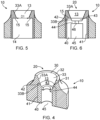
Figure 4 is a perspective cross-section of a locating formation in accordance with the invention shown with a sleeve in position; -
Figure 5 is a cross-section elevation of the locating formation ofFigure 4 but shown with the sleeve absent; -
Figure 6 is a cross-section elevation of the locating formation ofFigure 4 shown with a sleeve; -
Figure 7 is a cross-section elevation of the locating formation ofFigure 4 shown with a sleeve and exemplary dental abutment or implant feature in location; -
Figure 8 is a perspective view of an exemplary sleeve; -
Figure 9 is a dimensioned cross-section elevation of an exemplary locating formation in accordance with the invention; -
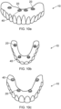
Figures 10a, 10b and 10c show exemplary dental prostheses comprising locating formations in accordance with the invention; -
Figures 11a ,12a and13a are perspective cross-sections of exemplary locating formations in accordance with the invention having domed shapes; and; -
Figures 11b ,12b and13b are cross-section elevations of the locating formations ofFigures 11a ,12a and13a , respectively. -
Figure 14 is a cross-section of an exemplary locating formation adapted for connection directly to an implant head of a Straumann® dental implant system. -
Figure 15a and 15b are cross-sections of an exemplary locating formation adapted for connection directly to an implant head of a Nobel Biocare® dental implant. - With reference to
Figure 1 there is shown an exemplary dental prosthesis 1 comprising a plurality of locatingformations 2 adapted for mounting the prosthesis to a dental implant fixture or feature (not shown) affixed to a patient's jaw, or to an intermediate dental abutment that is attached to the free end of a dental implant fixture (not shown) affixed to a patient's jaw. - With reference to
Figures 2, 3a and 3b , a known type of locatingformation 2 in a dental prosthesis 1 is formed having a taperedrecess 3 that is separated from a substantially cylindrical bore 4 (Figures 3a and 3b ) by a radially inwardly extending flange 5 (Figure 3a ). Thetapered recess 3 is shaped to accommodate and engage a dental abutment or an abutment multi-unit or adental implant feature 60 as shown schematically inFigure 3b . Anaperture 5A (Figure 3a ) defined byflange 5 permits the shank of a screw 6 (Figure 3b ) to extend through the locatingformation 2 viabore 4 in order to screw threadedly engage with a dental abutment ordental implant feature 60 as shown inFigure 3b . Asscrew 6 is tightened, the screw head engages the inwardly extendingflange 5 thereby drawing the prosthesis 1 into tighter engagement with the dental abutment ordental implant feature 60 thereby affixing the prosthesis firmly to the patient's jaw. InFigure 3b a gap is shown between the dental abutment ordental implant feature 60 and thetapered recess 3 of the locatingformation 2 however it will be appreciated that the dental abutment and the tapered recess features contact in use. - Such dental prostheses are commonly machined from a block of material, for example a ceramic or polymeric block, by computed aided milling, with the specific geometry of the prostheses and their respective locating formations in dependence upon data collated using digital technology and in relation to the intended recipients of said prostheses.
- With reference to
Figures 10a, 10b and 10c there is shown as series ofdental prostheses 10 each comprising a plurality of locatingformations 20 in accordance with the invention. -
Prostheses 10 in accordance with the invention are preferably polymeric prostheses having a composition consisting of polyetheretherketone (PEEK) polymer, preferably, PEEK-OPTIMA™ of melt viscosity (MV) 0.45kNsm-2 , simply referred to hereinafter as PEEK. Preferably still, the PEEK polymeric prostheses are formed from a JLIVORA™ Dental Disc made from said PEEK-OPTIMA™. -
Figures 4-7 ,9 and11a to 15 each show a cross-section of a segment of a PEEKdental prosthesis 10 in accordance with the invention at the region of a locatingformation 20. - With reference to
Figures 4 ,11a ,12a ,13a ,14 and 15 , locatingformations 20 comprise arecess 30 adapted to receive a dental abutment, abutment multi-unit, or a dental implant fixture. - As shown in
Figures 4, 6 ,11a, 11b ,12a, 12b ,13a, 13b and14 ,recess 30 comprises afirst recess portion 13 formed in the PEEK material of theprosthesis 10, and asecond recess portion 43 formed in asleeve 40 locatable in the prosthesis. - In the examples of
Figures 4-7 and9 ,recess 30 is shown having an inverted conical frustum shape. - In the examples of
Figures 11a to 13b ,recess 30 is shown having a domed shape. InFigures 12a to 13b the recess has a spherical dome-shape. - In the example of
Figure 14 which does not form part of the claimed invention,recess 30 is shown having a substantially cylindricalfirst recess portion 13 and a taperedsecond recess portion 43 defined by achamfer 48 around the circumference of an aperture provided though ahub 44 which separates saidsecond recess 43 portion from theinterior 45 of the sleeve as described below. - With reference to
Figure 4 , when taken as a whole, eachrecess 30 comprisesbase 31 and a top 32, wherein the base is narrower than the top such that thesidewall 33 of said recess tapers towards thebase 31. - In the example shown in
Figure 5 , thefirst recess portion 13 is a tapered recess. Thefirst recess 13 is formed in the PEEK material of the prosthesis, for example by computed aided milling or other suitable means. The first recess portion has an upper end and a lower end with atapered sidewall 33A thereinbetween. The lower end offirst recess portion 13 has a diameter D1. The tapered sidewall 33A has taper angle Φ (not shown). A bore 14 having a diameter greater than D1 is formed in theprosthesis 10 below and opposingfirst recess portion 13 such that an annular undercut 15 region is formed immediately below said lower end of the first recess portion. Thus thebore 14 is in communication with thefirst recess portion 13. - In the examples shown in
Figures 4-7 and9 ,recess 30 is shown as an inverted conical frustum-shaped recess having a taperedsidewall 33, however it will be appreciated that the recess may be any other suitable inverted frustum-shaped recess and may therefore comprise a plurality of sidewalls. - With reference to
Figures 4, 6 and8 ,sleeve 40 comprises a generallytubular wall 41 and anannular shoulder portion 42 having an inner and an outer perimeter, wherein the inner perimeter of theshoulder portion 42 defines the perimeter of arecess portion 43. InFigures 4-8 recess portion 43 is shown having a taperedsidewall 33B surrounding an internally offsethub 44 which separates saidrecess portion 43 from the substantiallycylindrical interior 45 of the sleeve.Recess portion 43 is thus the second recess portion ofrecess 30 in use. - The diameter D2 (
Figure 8 ) of the perimeter ofrecess portion 43 at its junction with theshoulder portion 42 is substantially the same as diameter D1 (Figure 5 ) of the lower end offirst recess portion 13 formed in the prosthesis. - The
shoulder portion 42 andhub 44 ofsleeve 40 lie on substantially parallel spaced apart planes which are substantially orthogonal to thewall 41. - The tapered
sidewall 33B has a taper angle Φ (not shown) which is substantially equal to the taper angle Φ of taperedsidewall 33A. Thus thefirst recess portion 13 and thesecond recess portion 43 are contiguous. -
Sleeve 40 is preferably manufactured from titanium or an alloy thereof, however other suitable materials or alloys may be used, for example, but not limited to Cobalt Chromium (Co-Cr), stainless steel, etc. - When
sleeve 40 is fully inserted withinbore 14 formed in the prosthesis as shown inFigure 6 , thetubular wall 41 ofsleeve 40 is in slidable abutment with the surface ofbore 14 andannular shoulder portion 42 ofsleeve 40 abuts annular undercutregion 15 immediately below thefirst recess portion 13. - As shown by way of example in
Figure 8 ,sleeve 40 is provided with akey formation 41a in order to prevent rotation of the sleeve relative the prosthesis. InFigure 8 the illustrated key comprises a flat surface on the exterior ofsidewall 41 of the sleeve which is adapted to engage with a complementary flat surface provided on bore 14 (not shown) however it will be appreciated that any suitable key arrangement may be employed, for example, but not limited to, ribs, ridges, notches and corresponding grooves, indentations, etc. - As described above with reference to
Figures 5 and8 , the respective diameters D1 and D2 offirst recess 13 andsecond recess 43 are substantially the same, and the taper angles Φ of the respective tapered sidewalls 33A and 33B ofrecesses sleeve 40 is located withinbore 14 as described above and as shown inFigures 4 and 6 , the first andsecond recess portions respective sidewalls sidewall 33 ofrecess 30. Thus a dental abutment, abutment multi-unit ordental implant fixture 60 located within the locating formation as shown inFigure 7 will be fully supported along its interface withrecess 30. As a result of the presence ofsleeve 40 at the interface between thePEEK prosthesis 10 anddental implant fixture 60, the locating formation of the present invention provides increased stability and strength to the connection between said prosthesis and dental implant fixture. - As shown in
Figure 7 , when a dental abutment or anabutment multi-unit 60 is located withinrecess 30, the surface ofhub 44proximate sidewall 33B ofrecess portion 43 ofsleeve 40 abuts the terminal end of said dental abutment or abutment multi-unit. - As shown in
Figure 7 , an aperture 46 (seeFigures 6 and8 ) provided thoughhub 44 permits the shank of ascrew 6, inserted via theinterior 45 of the sleeve to extend through saidsleeve 40 and intorecess 30 of locatingformation 20 to screw threadedly engage with thedental abutment 60. Asscrew 6 is tightened, the screw head engages the reverse side ofhub 44 thereby drawing theprosthesis 10 into tighter abutment with thedental abutment 60 thereby affixing the prosthesis firmly to the patient's jaw. - Referring to
Figure 9 , exemplary dimensions of a locating formation having an inverted conical frustum shape and comprising a titanium sleeve in accordance with the invention are shown. It will be appreciated that these exemplary dimensions apply also to titanium sleeves formed having a dome-shaped recess therein. In the example shown, the depth of the first recess portion 13 (i.e. formed in the polymer of the prosthesis) is approximately 1.7 mm; the depth of the second recess portion (i.e. formed in the sleeve) is approximately 0.6 mm (thus the depth ofrecess 30 is approximately 2.3 mm); the diameter D2 of thesecond recess portion 43 at its junction with theannular shoulder portion 42 is approximately 2.6mm (thus the diameter D1 of the lower end offirst recess portion 13 is also approximately 2.6mm); the width ofannular shoulder portion 42 is approximately 0.8 mm; the diameter of the sleeve is 4.2 mm. - Ideally the minimum thickness of the PEEK prosthesis surrounding the
sleeve 40 at it its closest point to the sleeve wall (i.e. perpendicularly adjacent the outer perimeter of annular shoulder 42) is 0.5 mm. - Preferably, the thickness of the PEEK prosthesis surrounding the sleeve at it its closest point to the outer diameter of the
sleeve wall sleeve 40 at it its closest point to the sleeve wall (i.e. perpendicularly adjacent the outer perimeter of annular shoulder 42) is at least 0.7 mm. - With reference to
Figures 11a-13b arecess 20 having a dome-shape is shown. Other than the specific shape of the recess defined by its first 13 and second 43 portions, the structure, function and form of a dome-shaped recess and associated reinforcingsleeve 40 is substantially the same as that described in respect of the examples above. - In the example shown in
Figures 11a and 11b , the first recess portion 13 (formed in the PEEK material of the prosthesis) and the second recess portion 43 (formed insleeve 40 locatable in the prosthesis) havecurved sidewalls curved sidewall 33 ofrecess 30. In theexample recess 30 has a substantiallyflat base 31. - In the example shown in
Figures 12a and 12b , therecess 20 is a spherical dome shape wherein the first recess portion 13 (formed in the PEEK material of the prosthesis) and the second recess portion 43 (formed in reinforcing sleeve 40) each have the shape of a spherical segment. Thusrecess 20 has contiguouscurved sidewalls flat base 31. The first 13 and second 43 recess portions have the same spherical radius R such that they are contiguous. - In the example shown in
Figures 13a and 13b , first recess portion 13 (formed in the PEEK material of the prosthesis) has the shape of a spherical segment while the second recess portion 13 (i.e. formed in the reinforcing sleeve) has the shape of a spherical cap. The first 13 and second 43 recess portions have the same spherical radius R such that they are contiguous, howeverrecess 30 is absent a flat base. - In the example shown in
Figure 14 , which is adapted for direct connection to an implant head of a Straumann® dental implant system, and which does not form part of the claimed invention, the first recess portion 13 (formed in the PEEK material of the prosthesis) is substantially cylindrical. Thesecond recess portion 43 is formed insleeve 40 and is defined by achamfer 48 provided onshoulder portion 42 and around the circumference ofaperture 46 provided thoughhub 44 which separates saidsecond recess portion 43 from theinterior 45 of the sleeve. Asecond chamfer 49 is provided around thehub 44 adjacent thecylindrical interior 45 of the sleeve. Anannular trough 51 formed around the cylindrical wall of thefirst recess portion 13 at a lower end of said first recess portion is adapted to engage flush with a corresponding feature of a Straumann® dental implant design, and on an external emergence profile to fit with the gum line in use. - In the example of
Figure 14 ,recess 30 is shown having a substantially cylindricalfirst recess portion 13 and a taperedsecond recess portion 43 defined by achamfer 48 around the circumference of an aperture provided though ahub 44 which separates saidsecond recess 43 portion from theinterior 45 of the sleeve as described below. - With reference to
Figures 15a and 15b , there is disclosed a reinforcing sleeve for location in abore 4 formed in dental prosthesis, the reinforcingsleeve 40 comprising a generallytubular wall 41 and having ahub 44 at one end and anopen bore 50 at an opposing end. Thehub 44 is provided with anaperture 46.Aperture 46 has a diameter that is less than the diameter of the opposingopen bore 50. The reinforcingsleeve 40 is insertable into thebore 4 formed in theprosthesis 10 such that thehub 44 abuts the underside of aflange 5 formed in said prosthesis, the flange being located intermediate thebore 4 and arecess 13. When located in the prosthesis in this way,aperture 46 aligns with anaperture 5A defined byflange 5A such that the shank of a screw (not shown) inserted into the prosthesis via theinterior 45 of the reinforcingsleeve 40 can extend through saidsleeve 40 and into therecess 13 formed in theprosthesis 10 in order to screw threadedly engage the head of a dental implant (not shown) located inrecess 13. As the screw (not shown) is tightened, the screw head will engage the underside of thehub 44 thereby drawing theprosthesis 10 into tighter engagement with the dental implant head. Such a reinforcing sleeve is particularly suited for use with Nobel Biocare® dental implant systems. - Reinforcement of the connection between a dental implant fixture and a
prosthesis 10 by the use of a locatingformation 20 comprising a reinforcingsleeve 40 in accordance with the invention enables a wider range of torque forces can be applied to the screw used to secure theprosthesis 10 to theimplant feature 60. - This is because the
sleeve 40 provides an interface between the screw and thepolymeric prosthesis 10 such that the screw does not directly impinge or contact the polymeric prosthesis, but rather the screw head engages the reverse side of thehub 44 of the sleeve. - Thus higher torque forces can be applied than otherwise would be possible without the presence of such a
sleeve 40. Accordingly, the sleeve provides increased stability and wider user flexibility when torqueing theprosthesis 10 to adental implant feature 60. - The
sleeve 40 allows for a more precise fit between the polymeric prosthesis and the implant interface improving the passivity of the system. Accordingly, thesleeve 40 allows for a greater degree of passivity seating when torqueing theprosthesis 10 to adental implant feature 60. -
Sleeves 40 also permit the use of screws having small or conical heads to secure aprosthesis 10 to animplant feature 60. Thus the invention permits the use of a wider range of dental implant systems, in particular dental implant features adapted to use abutment screws carrying conical and small screw heads. - Advantageously, the small size of the sleeve (approximately 4.2 mm diameter) mitigates its impact on the overall dimensions of a polymeric prosthesis adapted to receive such a sleeve. Thus prostheses in accordance with the invention achieve maximum stability with minimal dimensional change required to said prostheses.
Claims (15)
- A dental prosthesis (10) formed of a composition comprising a polymeric material, the prosthesis comprising one or more locating formations (20) adapted to receive a dental implant fixture or dental abutment, the or each locating formation comprising a recess (30) comprising a first recess portion (13) formed in the polymeric material of the prosthesis (10), and a second recess portion (43) provided in a sleeve (40) located in the prosthesis, characterised in that the recess (30) has an inverted frustum-shape.
- A dental prosthesis (10) formed of a composition comprising a polymeric material, the prosthesis comprising one or more locating formations (20) adapted to receive a dental implant fixture or dental abutment, the or each locating formation comprising a recess (30) comprising a first recess portion (13) formed in the polymeric material of the prosthesis (10), and a second recess portion (43) provided in a sleeve (40) located in the prosthesis, characterised in that the recess (30) is dome shaped.
- A dental prosthesis as claimed in any preceding claim, wherein the recess (30) comprises a base (31) and a top (32), wherein the base is narrower than the top such that a sidewall (33) of said recess tapers towards the base (31).
- A dental prosthesis as claimed in claim 1 or claim 3 when dependent upon claim 1, wherein the recess (30) has an inverted conical frustum shape.
- A dental prosthesis as claimed in claim 1 or claim 3 when dependent upon claim 1, wherein the first recess portion (13) is substantially cylindrical and the second recess portion (43) is tapered.
- A dental prosthesis as claimed in any preceding claim, wherein the first recess portion (13) and the second recess portion (43) are contiguous.
- A dental prosthesis as claimed in claim 1 or in any one of claims 3 to 6 when dependent upon claim 1, wherein the first recess portion (13) has an upper end and a lower end with a sidewall (33A) extending thereinbetween, optionally wherein the sidewall (33A) of the first recess portion is a tapered sidewall having a taper angle Φ, and/or further comprising a bore (14) formed below and opposing the first recess portion (13), the bore having a having a diameter greater than the diameter of the lower end of the first recess portion such that an annular undercut (15) region is formed immediately below the lower end of the first recess portion (13).
- A dental prosthesis as claimed in claim 2, or in claims 3 or 6 when dependent upon claim 2, wherein the first recess portion (13) has an upper end and a lower end with a sidewall (33A) extending thereinbetween, optionally wherein the sidewall of the first recess portion (33A) is a curved sidewall having a radius of curvature R, and/or further comprising a bore (14) formed below and opposing the first recess portion (13), the bore having a having a diameter greater than the diameter of the lower end of the first recess portion such that an annular undercut (15) region is formed immediately below the lower end of the first recess portion.
- A dental prosthesis as claimed in claim 1 or in any one of claims 3 to 7 when dependent upon claim 1, wherein the sleeve (40) comprises a generally tubular wall (41) and an annular shoulder portion (42), wherein the inner perimeter of the annular shoulder portion (42) defines the perimeter of the second recess portion (43), and optionally wherein the diameter of the perimeter of the second recess portion (43) is substantially equal to the diameter of the lower end of the first recess portion (13), and further optionally wherein the second recess portion (43) comprises an annular sidewall surrounding a hub (44) that is internally offset from the shoulder portion (42) and which separates said second recess portion from the interior (45) of the sleeve (40), and further optionally wherein the annular sidewall of the second recess portion is a tapered sidewall (33B) having a taper angle Φ that is substantially the same as a taper angle Φ of the sidewall (33A) of the first recessed portion (13), , and further optionally wherein the second recess portion (43) is defined by a chamfer provided on the shoulder portion and around the circumference of an aperture (46) provided though the hub (44).
- A dental prosthesis as claimed in claim 2, or in any one of claims 3, 6 or 7 when dependent upon claim 2 wherein the sleeve (40) comprises a generally tubular wall (41) and an annular shoulder portion (42), wherein the inner perimeter of the annular shoulder portion (42) defines the perimeter of the second recess portion (43), and optionally wherein the diameter of the perimeter of the second recess portion is substantially equal to the diameter of the lower end of the first recess portion (13), and further optionally wherein the second recess portion (43) comprises an annular sidewall surrounding a hub (44) that is internally offset from the shoulder portion (42) and which separates said second recess portion from the interior (45) of the sleeve (40), and further optionally wherein the annular sidewall of the second recess portion is a curved sidewall (33B) having a radius of curvature R that is substantially the same as a radius of curvature R of the sidewall (33A) of the first recessed portion (13), and further optionally wherein the second recess portion (43) is defined by a chamfer provided on the shoulder portion and around the circumference of an aperture (46) provided though the hub (44).
- A dental prosthesis as claimed in claim 9 or claim 10, wherein the annular shoulder portion (42) and the hub (44) lie on substantially parallel spaced apart planes which are substantially orthogonal to the generally tubular wall (41) of said sleeve (40).
- A dental prosthesis as claimed in any one of claims 9 to 11, wherein the sleeve (40) is slidably locatable into the bore formed in the prosthesis below and opposing the first recess portion (13) such that the generally tubular wall (41) of said sleeve is in abutment with the surface of said bore and the annular shoulder portion (42) of said sleeve abuts the annular undercut region (15) immediately below the lower end of the first recess portion (13), and optionally wherein the sleeve (40) comprises means to prevent rotation of the sleeve relative to the prosthesis, and optionally wherein the means to prevent rotation of the sleeve relative the prosthesis comprises a key formation (41a) on the outer surface of the sleeve wall which is adapted to engage with a complementary key formation provided on or in the bore (14) formed in the prosthesis below and opposing the first recess portion (13), and further optionally wherein the respective key formations comprise one or more complementary flat portions provided on the respective opposing surfaces of the sleeve and bore.
- A dental prosthesis as claimed in any preceding claim, wherein the depth of the first recess portion (13) is approximately 1.7 mm, and optionally wherein the depth of the second recess portion (43) is approximately 0.6 mm.
- A dental prosthesis as claimed in claim 9 or claim 10, wherein the diameters of the perimeter of the second recess portion (43) and the lower end of the first recess portion (13) are approximately 2.6mm, and optionally, wherein the width of the annular shoulder portion of the sleeve (42) is approximately 0.8 mm, and optionally wherein the minimum thickness of the prosthesis surrounding the sleeve adjacent the outer perimeter of the annular shoulder (42) of the sleeve is approximately 0.5 mm, and optionally wherein the thickness of the prosthesis surrounding the sleeve adjacent the outer perimeter of the annular shoulder (42) of the sleeve is at least 0.7 mm.
- A dental prosthesis as claimed in any preceding claim, wherein the polymeric material of the prosthesis preferably comprises a repeat unit of formula (I):

Applications Claiming Priority (2)
| Application Number | Priority Date | Filing Date | Title |
|---|---|---|---|
| GBGB1711004.0A GB201711004D0 (en) | 2017-07-07 | 2017-07-07 | Dental Prosthesis |
| PCT/GB2018/051899 WO2019008368A1 (en) | 2017-07-07 | 2018-07-05 | Dental prosthesis |
Publications (3)
| Publication Number | Publication Date |
|---|---|
| EP3648702A1 EP3648702A1 (en) | 2020-05-13 |
| EP3648702B1 true EP3648702B1 (en) | 2024-08-07 |
| EP3648702C0 EP3648702C0 (en) | 2024-08-07 |
Family
ID=59676760
Family Applications (1)
| Application Number | Title | Priority Date | Filing Date |
|---|---|---|---|
| EP18755877.0A Active EP3648702B1 (en) | 2017-07-07 | 2018-07-05 | Dental prosthesis |
Country Status (7)
| Country | Link |
|---|---|
| US (2) | US12303351B2 (en) |
| EP (1) | EP3648702B1 (en) |
| ES (1) | ES2991489T3 (en) |
| GB (1) | GB201711004D0 (en) |
| HU (1) | HUE068202T2 (en) |
| PL (1) | PL3648702T3 (en) |
| WO (1) | WO2019008368A1 (en) |
Families Citing this family (1)
| Publication number | Priority date | Publication date | Assignee | Title |
|---|---|---|---|---|
| US20240390117A1 (en) * | 2023-05-23 | 2024-11-28 | Opa Dental, LLC | Dental prosthetic appliance |
Citations (4)
| Publication number | Priority date | Publication date | Assignee | Title |
|---|---|---|---|---|
| US5078606A (en) * | 1987-04-22 | 1992-01-07 | Astra Meditec Aktiebolag | Method for affixing a dental prosthesis |
| US20140272792A1 (en) * | 2013-03-15 | 2014-09-18 | Harry A. HARALAMPOPOULOS | Conversion abutment for dental implants |
| FR3036032A1 (en) * | 2015-05-12 | 2016-11-18 | Biotech Dental | DENTAL PILLAR WITH SCREW BRAKE AND DENTAL PROSTHESIS USING SUCH PILLAR |
| EP3289997A1 (en) * | 2016-08-29 | 2018-03-07 | Kulzer GmbH | Connector-adapter device for round-head attachments of dental prostheses |
Family Cites Families (15)
| Publication number | Priority date | Publication date | Assignee | Title |
|---|---|---|---|---|
| FR1319420A (en) * | 1962-01-18 | 1963-03-01 | Attachment for dental prostheses, and method of making it | |
| US4850870C1 (en) * | 1987-10-23 | 2001-07-24 | Implant Innovations Inc | Prosthodontic restoration components |
| US5006069A (en) * | 1988-11-02 | 1991-04-09 | Implant Innovations, Inc. | Periodontal restoration components |
| US5040982A (en) * | 1990-06-28 | 1991-08-20 | Stefan Dogar Sorin | Dental implant and conversion assembly |
| US5873721A (en) * | 1993-12-23 | 1999-02-23 | Adt Advanced Dental Technologies, Ltd. | Implant abutment systems, devices, and techniques |
| CH690986A5 (en) * | 1995-03-22 | 2001-03-30 | Francois Clerc | attachment device for dental prosthesis. |
| US20100145393A1 (en) * | 2008-12-05 | 2010-06-10 | Medicinelodge, Inc. | Medical and dental porous implants |
| WO2011069226A1 (en) * | 2009-12-11 | 2011-06-16 | Harold Robert Bergman | Apparatus, method, and system for holding a denture |
| EP2351536B1 (en) | 2010-02-02 | 2016-04-13 | Straumann Holding AG | Method of producing an implant-supported dental prosthesis by using a multi-functional adapter. |
| DE202010017227U1 (en) * | 2010-04-29 | 2011-04-21 | Nt-Trading Gmbh & Co. Kg | Abutment for dental implant |
| US9168111B2 (en) * | 2011-02-04 | 2015-10-27 | Rodo Medical, Inc. | Abutment devices and methods for natural teeth |
| WO2013142350A1 (en) * | 2012-03-23 | 2013-09-26 | 53M Innovative Properties Company | Housing for dental implants |
| PT3082644T (en) * | 2013-12-19 | 2017-10-27 | Juvora Ltd | Dental frameworks and related apparatus and methods |
| EP2904987B1 (en) | 2014-02-11 | 2018-12-19 | Kulzer GmbH | Dental prosthesis with dampening insert |
| DE102016111646A1 (en) * | 2016-06-24 | 2017-12-28 | Bredent Gmbh & Co. Kg | Shell for adaptation of a retention element and method thereto |
-
2017
- 2017-07-07 GB GBGB1711004.0A patent/GB201711004D0/en not_active Ceased
-
2018
- 2018-07-05 PL PL18755877.0T patent/PL3648702T3/en unknown
- 2018-07-05 ES ES18755877T patent/ES2991489T3/en active Active
- 2018-07-05 HU HUE18755877A patent/HUE068202T2/en unknown
- 2018-07-05 US US16/628,876 patent/US12303351B2/en active Active
- 2018-07-05 WO PCT/GB2018/051899 patent/WO2019008368A1/en not_active Ceased
- 2018-07-05 EP EP18755877.0A patent/EP3648702B1/en active Active
-
2023
- 2023-03-27 US US18/190,752 patent/US20230225837A1/en not_active Abandoned
Patent Citations (4)
| Publication number | Priority date | Publication date | Assignee | Title |
|---|---|---|---|---|
| US5078606A (en) * | 1987-04-22 | 1992-01-07 | Astra Meditec Aktiebolag | Method for affixing a dental prosthesis |
| US20140272792A1 (en) * | 2013-03-15 | 2014-09-18 | Harry A. HARALAMPOPOULOS | Conversion abutment for dental implants |
| FR3036032A1 (en) * | 2015-05-12 | 2016-11-18 | Biotech Dental | DENTAL PILLAR WITH SCREW BRAKE AND DENTAL PROSTHESIS USING SUCH PILLAR |
| EP3289997A1 (en) * | 2016-08-29 | 2018-03-07 | Kulzer GmbH | Connector-adapter device for round-head attachments of dental prostheses |
Also Published As
| Publication number | Publication date |
|---|---|
| US20230225837A1 (en) | 2023-07-20 |
| HUE068202T2 (en) | 2024-12-28 |
| EP3648702C0 (en) | 2024-08-07 |
| WO2019008368A1 (en) | 2019-01-10 |
| GB201711004D0 (en) | 2017-08-23 |
| US20200222153A1 (en) | 2020-07-16 |
| PL3648702T3 (en) | 2024-11-12 |
| US12303351B2 (en) | 2025-05-20 |
| ES2991489T3 (en) | 2024-12-03 |
| EP3648702A1 (en) | 2020-05-13 |
Similar Documents
| Publication | Publication Date | Title |
|---|---|---|
| US9629697B2 (en) | Prosthodontic device | |
| EP2901963B1 (en) | Dental superstructure, and a method of manufacture thereof | |
| US10383710B2 (en) | Configurations for the connection of dental restorations with abutments | |
| EP1994907B1 (en) | Try-in implant | |
| EP2282694B1 (en) | Two-part dental implant | |
| US8992221B2 (en) | Denture system | |
| US20190307534A1 (en) | Implant made of fibre-reinforced plastic | |
| EP3082641B1 (en) | Dental implant incorporating an apatite | |
| EP2309945A1 (en) | Modular implant with secured porous portion | |
| CN106456290B (en) | Denture manufacturing device and denture | |
| US20230225837A1 (en) | Dental prosthesis | |
| US20180140393A1 (en) | Customized single piece dental implant | |
| EP3007645A1 (en) | Dental prosthesis and a method for making the prosthesis | |
| JP2021526400A (en) | Central gingival implant system | |
| SE509522C2 (en) | Method and apparatus for effecting cemented superstructure as well as spacers and range of spacers | |
| US8951043B2 (en) | Insertion part of a two-part implant with insertion instrument | |
| WO2019063127A1 (en) | Arrangement and method for fabricating custom implant abutments | |
| US20240156602A1 (en) | Osteotomy gap filling implant and methods | |
| CN112469362A (en) | Base station with embedded screw | |
| EP4186463B1 (en) | Artificial tooth and manufacturing method therefor | |
| US20220133442A1 (en) | Impression post for connection to a dental implant | |
| WO2018185463A1 (en) | A dental implant and dental prosthesis system and method | |
| JP3261009B2 (en) | Biological implant | |
| HK1153922A (en) | Two-part dental implant | |
| HK1153922B (en) | Two-part dental implant |
Legal Events
| Date | Code | Title | Description |
|---|---|---|---|
| STAA | Information on the status of an ep patent application or granted ep patent |
Free format text: STATUS: UNKNOWN |
|
| STAA | Information on the status of an ep patent application or granted ep patent |
Free format text: STATUS: THE INTERNATIONAL PUBLICATION HAS BEEN MADE |
|
| PUAI | Public reference made under article 153(3) epc to a published international application that has entered the european phase |
Free format text: ORIGINAL CODE: 0009012 |
|
| STAA | Information on the status of an ep patent application or granted ep patent |
Free format text: STATUS: REQUEST FOR EXAMINATION WAS MADE |
|
| 17P | Request for examination filed |
Effective date: 20200121 |
|
| AK | Designated contracting states |
Kind code of ref document: A1 Designated state(s): AL AT BE BG CH CY CZ DE DK EE ES FI FR GB GR HR HU IE IS IT LI LT LU LV MC MK MT NL NO PL PT RO RS SE SI SK SM TR |
|
| AX | Request for extension of the european patent |
Extension state: BA ME |
|
| RIN1 | Information on inventor provided before grant (corrected) |
Inventor name: SERENO, NUNO Inventor name: SILVA, ANTONIO Inventor name: GUEDES, CARLOS MOURA Inventor name: DE ARAUJO NOBRE, MIGUEL Inventor name: ALMEIDA, RICARDO Inventor name: LEGATHEAUX, JOAO Inventor name: MALO, PAULO |
|
| DAV | Request for validation of the european patent (deleted) | ||
| DAX | Request for extension of the european patent (deleted) | ||
| STAA | Information on the status of an ep patent application or granted ep patent |
Free format text: STATUS: EXAMINATION IS IN PROGRESS |
|
| 17Q | First examination report despatched |
Effective date: 20221031 |
|
| RAP1 | Party data changed (applicant data changed or rights of an application transferred) |
Owner name: MALO CLINIC, S.A. |
|
| GRAP | Despatch of communication of intention to grant a patent |
Free format text: ORIGINAL CODE: EPIDOSNIGR1 |
|
| STAA | Information on the status of an ep patent application or granted ep patent |
Free format text: STATUS: GRANT OF PATENT IS INTENDED |
|
| INTG | Intention to grant announced |
Effective date: 20240313 |
|
| GRAS | Grant fee paid |
Free format text: ORIGINAL CODE: EPIDOSNIGR3 |
|
| GRAA | (expected) grant |
Free format text: ORIGINAL CODE: 0009210 |
|
| STAA | Information on the status of an ep patent application or granted ep patent |
Free format text: STATUS: THE PATENT HAS BEEN GRANTED |
|
| AK | Designated contracting states |
Kind code of ref document: B1 Designated state(s): AL AT BE BG CH CY CZ DE DK EE ES FI FR GB GR HR HU IE IS IT LI LT LU LV MC MK MT NL NO PL PT RO RS SE SI SK SM TR |
|
| REG | Reference to a national code |
Ref country code: GB Ref legal event code: FG4D |
|
| REG | Reference to a national code |
Ref country code: CH Ref legal event code: EP |
|
| REG | Reference to a national code |
Ref country code: IE Ref legal event code: FG4D |
|
| REG | Reference to a national code |
Ref country code: DE Ref legal event code: R096 Ref document number: 602018072770 Country of ref document: DE |
|
| U01 | Request for unitary effect filed |
Effective date: 20240821 |
|
| U07 | Unitary effect registered |
Designated state(s): AT BE BG DE DK EE FI FR IT LT LU LV MT NL PT RO SE SI Effective date: 20240902 |
|
| REG | Reference to a national code |
Ref country code: SK Ref legal event code: T3 Ref document number: E 44879 Country of ref document: SK |
|
| REG | Reference to a national code |
Ref country code: ES Ref legal event code: FG2A Ref document number: 2991489 Country of ref document: ES Kind code of ref document: T3 Effective date: 20241203 |
|
| REG | Reference to a national code |
Ref country code: HU Ref legal event code: AG4A Ref document number: E068202 Country of ref document: HU |
|
| PG25 | Lapsed in a contracting state [announced via postgrant information from national office to epo] |
Ref country code: GR Free format text: LAPSE BECAUSE OF FAILURE TO SUBMIT A TRANSLATION OF THE DESCRIPTION OR TO PAY THE FEE WITHIN THE PRESCRIBED TIME-LIMIT Effective date: 20241108 |
|
| PG25 | Lapsed in a contracting state [announced via postgrant information from national office to epo] |
Ref country code: IS Free format text: LAPSE BECAUSE OF FAILURE TO SUBMIT A TRANSLATION OF THE DESCRIPTION OR TO PAY THE FEE WITHIN THE PRESCRIBED TIME-LIMIT Effective date: 20241207 |
|
| PG25 | Lapsed in a contracting state [announced via postgrant information from national office to epo] |
Ref country code: HR Free format text: LAPSE BECAUSE OF FAILURE TO SUBMIT A TRANSLATION OF THE DESCRIPTION OR TO PAY THE FEE WITHIN THE PRESCRIBED TIME-LIMIT Effective date: 20240807 |
|
| PG25 | Lapsed in a contracting state [announced via postgrant information from national office to epo] |
Ref country code: RS Free format text: LAPSE BECAUSE OF FAILURE TO SUBMIT A TRANSLATION OF THE DESCRIPTION OR TO PAY THE FEE WITHIN THE PRESCRIBED TIME-LIMIT Effective date: 20241107 |
|
| PG25 | Lapsed in a contracting state [announced via postgrant information from national office to epo] |
Ref country code: RS Free format text: LAPSE BECAUSE OF FAILURE TO SUBMIT A TRANSLATION OF THE DESCRIPTION OR TO PAY THE FEE WITHIN THE PRESCRIBED TIME-LIMIT Effective date: 20241107 Ref country code: IS Free format text: LAPSE BECAUSE OF FAILURE TO SUBMIT A TRANSLATION OF THE DESCRIPTION OR TO PAY THE FEE WITHIN THE PRESCRIBED TIME-LIMIT Effective date: 20241207 Ref country code: HR Free format text: LAPSE BECAUSE OF FAILURE TO SUBMIT A TRANSLATION OF THE DESCRIPTION OR TO PAY THE FEE WITHIN THE PRESCRIBED TIME-LIMIT Effective date: 20240807 Ref country code: GR Free format text: LAPSE BECAUSE OF FAILURE TO SUBMIT A TRANSLATION OF THE DESCRIPTION OR TO PAY THE FEE WITHIN THE PRESCRIBED TIME-LIMIT Effective date: 20241108 |
|
| PG25 | Lapsed in a contracting state [announced via postgrant information from national office to epo] |
Ref country code: SM Free format text: LAPSE BECAUSE OF FAILURE TO SUBMIT A TRANSLATION OF THE DESCRIPTION OR TO PAY THE FEE WITHIN THE PRESCRIBED TIME-LIMIT Effective date: 20240807 |
|
| PLBE | No opposition filed within time limit |
Free format text: ORIGINAL CODE: 0009261 |
|
| STAA | Information on the status of an ep patent application or granted ep patent |
Free format text: STATUS: NO OPPOSITION FILED WITHIN TIME LIMIT |
|
| U20 | Renewal fee for the european patent with unitary effect paid |
Year of fee payment: 8 Effective date: 20250519 |
|
| PGFP | Annual fee paid to national office [announced via postgrant information from national office to epo] |
Ref country code: PL Payment date: 20250528 Year of fee payment: 8 |
|
| PGFP | Annual fee paid to national office [announced via postgrant information from national office to epo] |
Ref country code: GB Payment date: 20250514 Year of fee payment: 8 |
|
| 26N | No opposition filed |
Effective date: 20250508 |
|
| PGFP | Annual fee paid to national office [announced via postgrant information from national office to epo] |
Ref country code: TR Payment date: 20250627 Year of fee payment: 8 |
|
| PGFP | Annual fee paid to national office [announced via postgrant information from national office to epo] |
Ref country code: CZ Payment date: 20250618 Year of fee payment: 8 |
|
| PGFP | Annual fee paid to national office [announced via postgrant information from national office to epo] |
Ref country code: IE Payment date: 20250514 Year of fee payment: 8 |
|
| PGFP | Annual fee paid to national office [announced via postgrant information from national office to epo] |
Ref country code: HU Payment date: 20250610 Year of fee payment: 8 |
|
| PGFP | Annual fee paid to national office [announced via postgrant information from national office to epo] |
Ref country code: ES Payment date: 20250805 Year of fee payment: 8 |
|
| PGFP | Annual fee paid to national office [announced via postgrant information from national office to epo] |
Ref country code: NO Payment date: 20250709 Year of fee payment: 8 |
|
| PGFP | Annual fee paid to national office [announced via postgrant information from national office to epo] |
Ref country code: CH Payment date: 20250801 Year of fee payment: 8 |
|
| PGFP | Annual fee paid to national office [announced via postgrant information from national office to epo] |
Ref country code: SK Payment date: 20260209 Year of fee payment: 9 |