EP3648701B1 - Dental prosthetic device and corresponding intermediate component - Google Patents
Dental prosthetic device and corresponding intermediate component Download PDFInfo
- Publication number
- EP3648701B1 EP3648701B1 EP18749575.9A EP18749575A EP3648701B1 EP 3648701 B1 EP3648701 B1 EP 3648701B1 EP 18749575 A EP18749575 A EP 18749575A EP 3648701 B1 EP3648701 B1 EP 3648701B1
- Authority
- EP
- European Patent Office
- Prior art keywords
- component
- conical
- axial
- axial cavity
- intermediate connection
- Prior art date
- Legal status (The legal status is an assumption and is not a legal conclusion. Google has not performed a legal analysis and makes no representation as to the accuracy of the status listed.)
- Active
Links
Images

Classifications
-
- A—HUMAN NECESSITIES
- A61—MEDICAL OR VETERINARY SCIENCE; HYGIENE
- A61C—DENTISTRY; APPARATUS OR METHODS FOR ORAL OR DENTAL HYGIENE
- A61C8/00—Means to be fixed to the jaw-bone for consolidating natural teeth or for fixing dental prostheses thereon; Dental implants; Implanting tools
- A61C8/0048—Connecting the upper structure to the implant, e.g. bridging bars
- A61C8/0078—Connecting the upper structure to the implant, e.g. bridging bars with platform switching, i.e. platform between implant and abutment
-
- A—HUMAN NECESSITIES
- A61—MEDICAL OR VETERINARY SCIENCE; HYGIENE
- A61C—DENTISTRY; APPARATUS OR METHODS FOR ORAL OR DENTAL HYGIENE
- A61C8/00—Means to be fixed to the jaw-bone for consolidating natural teeth or for fixing dental prostheses thereon; Dental implants; Implanting tools
- A61C8/0048—Connecting the upper structure to the implant, e.g. bridging bars
- A61C8/005—Connecting devices for joining an upper structure with an implant member, e.g. spacers
- A61C8/0068—Connecting devices for joining an upper structure with an implant member, e.g. spacers with an additional screw
-
- A—HUMAN NECESSITIES
- A61—MEDICAL OR VETERINARY SCIENCE; HYGIENE
- A61C—DENTISTRY; APPARATUS OR METHODS FOR ORAL OR DENTAL HYGIENE
- A61C8/00—Means to be fixed to the jaw-bone for consolidating natural teeth or for fixing dental prostheses thereon; Dental implants; Implanting tools
- A61C8/0048—Connecting the upper structure to the implant, e.g. bridging bars
- A61C8/005—Connecting devices for joining an upper structure with an implant member, e.g. spacers
-
- A—HUMAN NECESSITIES
- A61—MEDICAL OR VETERINARY SCIENCE; HYGIENE
- A61C—DENTISTRY; APPARATUS OR METHODS FOR ORAL OR DENTAL HYGIENE
- A61C8/00—Means to be fixed to the jaw-bone for consolidating natural teeth or for fixing dental prostheses thereon; Dental implants; Implanting tools
- A61C8/0048—Connecting the upper structure to the implant, e.g. bridging bars
- A61C8/005—Connecting devices for joining an upper structure with an implant member, e.g. spacers
- A61C8/0069—Connecting devices for joining an upper structure with an implant member, e.g. spacers tapered or conical connection
-
- A—HUMAN NECESSITIES
- A61—MEDICAL OR VETERINARY SCIENCE; HYGIENE
- A61C—DENTISTRY; APPARATUS OR METHODS FOR ORAL OR DENTAL HYGIENE
- A61C8/00—Means to be fixed to the jaw-bone for consolidating natural teeth or for fixing dental prostheses thereon; Dental implants; Implanting tools
- A61C8/0048—Connecting the upper structure to the implant, e.g. bridging bars
- A61C8/005—Connecting devices for joining an upper structure with an implant member, e.g. spacers
- A61C8/0074—Connecting devices for joining an upper structure with an implant member, e.g. spacers with external threads
-
- A—HUMAN NECESSITIES
- A61—MEDICAL OR VETERINARY SCIENCE; HYGIENE
- A61C—DENTISTRY; APPARATUS OR METHODS FOR ORAL OR DENTAL HYGIENE
- A61C8/00—Means to be fixed to the jaw-bone for consolidating natural teeth or for fixing dental prostheses thereon; Dental implants; Implanting tools
- A61C8/0093—Features of implants not otherwise provided for
Definitions
- Embodiments described here concern a dental prosthetic device for dental use.
- Embodiments described here also concern an intermediate connection component for said dental prosthetic device, in which the connection component connects two components of the dental prosthetic device with each other, that is, a first component, or intraosseous implant, and a second component, or stump.
- Dental prosthetic devices comprising a first component, also called an intraosseous implant, a second component, also referred to as a stump or abutment, and possibly a prosthetic component to replace the crown of the tooth.
- the above three elements are installed in the patient's mouth on three different levels starting from the bone part, passing through the gingival part and finally in the external part in correspondence with the dental arch.
- the first component, or intraosseous implant normally has the shape of a threaded screw, it is fixed, or anchored, by screwing it into a corresponding hole present, or made, in the bone part, the maxillary or mandibular bone, where the patient's teeth are.
- the second component couples with the intraosseous implant at a later stage than the first installation of the first intraosseous component, after a time interval long enough to allow the first intraosseous component to stabilize in the patient's mouth.
- the stabilization of the first intraosseous component consists in waiting for osseointegration to occur between the first intraosseous component and the patient's bone part.
- This intervention can cause problems due to poor cleaning of the wound which, for example, can cause infections.
- this type of second component does not allow to adjust the inclination of the dental prosthesis if the need arises, for example if the first intraosseous component has been installed inclined already at the beginning.
- dental prosthetic devices are described in US-A-2014/0147812 , US-B-5.030.095 , US-A-2016/0206409 , US-B-5.368.483 , and KR-A-2016.0072634 .
- WO 2017/090037 A1 discloses a prosthetic dental device, an axial-symmetric intermediate connection component for a prosthetic dental device comprising a first axial-symmetric intraosseus component or implant, and a combination of a first axial-symmetric intraosseus component, or implant, and an axial-symmetric intermediate connection component, according to the preamble of claims 1, 10, and 11, respectively.
- a dental prosthetic device that comprises an intraosseous implant which is anchored to the patient's bone part and a stump, or "abutment” which is attached in various ways to the intraosseous implant.
- All these solutions due to the conformation of their components, require that, after the stabilization phase of the implant to the bone part, there is a subsequent intervention on the patient, rather invasive, which is the laceration of the gingival part and sometimes even of a portion of the intraosseous part that has reformed in correspondence with the implant.
- One purpose of the present invention is to provide a dental prosthetic implant which facilitates the intervention operations for its installation.
- Another purpose of the present invention is to provide a dental prosthetic implant which reduces the probability of the onset of infections.
- Another purpose is to provide a dental prosthetic implant that guarantees the success of the intervention.
- Another purpose is to provide a dental prosthetic implant which also satisfies aesthetic requirements.
- Another purpose is to provide a connection component which guarantees versatility of use also with the work in progress between one intervention and another.
- the Applicant has devised, tested and embodied the present invention to overcome the shortcomings of the state of the art and to obtain these and other purposes and advantages.
- a prosthetic dental device comprises a first axial-symmetric intraosseus component, or implant, in which a first axial cavity is made, open toward the outside, partly threaded and provided with a conical wall.
- the prosthetic dental device also comprises a second component, or abutment, configured to be connected on one side to the first intraosseus component and to support, on another side, a prosthetic dental component;
- the prosthetic dental device comprises an axial-symmetric intermediate connection component provided with a distal part with a second axial cavity open toward the outside, a proximal part provided externally with a threaded portion that, during use, is screwed into the first axial cavity, and an intermediate part located between the distal part and the proximal part and provided with at least a conical portion, converging toward the proximal part and coupled with conicity to the conical wall.
- the second axial cavity of the intermediate connection component is provided with a conical part and a threaded part more internal with respect to the conical part, with a diameter of threading equal to that of the threaded portion.
- the conical portion of the intermediate part has a conicity equal to the conicity of the conical part of the second axial cavity.
- the intermediate connection component can be considered an extension of a collar of the first intraosseus component.
- the present invention provides that the conformation of the first axial cavity of the first component, or implant, is substantially equal to that of the second axial cavity of the intermediate connection component.
- connection zone of the second component to the intermediate connection component is equal to the connection zone of the first component to the intermediate connection component, it is possible to rapidly change, during the course of the intervention, the implanting process of the prosthetic dental device.
- the intermediate connection component allows to rapidly change the implanting process of a prosthetic tooth passing from an initial installation of the first intraosseus component of the juxta type, that is, a first intraosseus component at the level of the bone part, or of the sub-crestal type, that is, a first intraosseus component below the bone part, to a trans-gingival installation. Moreover, in this way, the regeneration of the soft tissue to preimplant conditions is guaranteed.
- the particular conformation of the dental prosthetic device allows to assemble the second component, or abutment, to the implant, in a classic mode in which the first intraosseus component is installed in the juxta configuration, or, in accordance with the present invention, allows to be able to position the same implant below the bone part and to associate with it the intermediate connection component and the second component, or abutment as described above.
- the interface zone between the first component or implant and the intermediate connection component is positioned completely inside the intraosseus part and is therefore protected from possible infiltrations, contaminations and infections.
- the intermediate connection component allows to be able to modulate the height of the installation of the second component, moving its terminal end beyond the bone part, for example on the level of the gingival part.
- the intermediate connection component can be suitably chosen, even following the osteointegration of the intraosseus implant, as a function of the particular conformation of the transosseous and transmucous zone of the specific patient in whom the device is applied.
- the intermediate connection component allows to choose at a later time, and possibly change, the prosthetic approach initially chosen, between a cemented and screwed in prosthesis or prosthetic pins, or to change the second component in the course of the intervention, which can be standard or personalized using a graphical processing software, or by melting a calcinable component.
- the intermediate part is also provided with a central portion having a surface configured to promote the regrowth of gum and/or bone tissue, and with a second portion provided between the central portion and the distal part and having a shape rounded and flared toward the proximal part.
- the second portion allows to promote the regeneration of the gingival part avoiding the presence of protruding angles that could weaken the formation of the gingival part.
- the present invention also concerns an intermediate connection component for a dental prosthetic device.
- the present invention also concerns the combination of a first intraosseus component and an intermediate connection component.
- Embodiments described here using figs. 1-6 concern a dental prosthetic device 10 that comprises a first component, hereafter referred to as an axialsymmetrical intraosseous implant 11 and a second component, hereinafter referred to as the abutment 12.
- a first axial cavity 24 is made in the intraosseous implant 11, open toward the outside and at least partly threaded.
- the device 10 also comprises an intermediate connection component 13, also axial-symmetric, able to be disposed between the intraosseous implant 11 and the abutment 12.
- the intermediate connection component 13 is configured to connect the intraosseous implant 11 and the abutment 12 during use.
- the intermediate connection component 13 is put on the intraosseous implant 11 and connected to the latter with first connection means 51.
- the abutment 12 is instead put on the intermediate connection component 13 and is connected to the latter by second connection means 52.
- the intraosseous implant 11 and the abutment 12 are therefore not in contact with each other.
- the first connection means 51 and the second connection means 52 are separated and independent of each other in order to allow the selective removal/installation of the intermediate connection component 13 and/or of the abutment 12 independently of each other.
- the intermediate connection component 13 develops axially around a central axis X ( fig. 2 ).
- the intermediate connection component 13 comprises a distal part 15 in which a second axial cavity 32 is made, open toward the outside.
- the abutment 12 is connected with the second connection means 52 in the second axial cavity 32.
- the second axial cavity 32 is provided with a conical part 34 and a threaded part 33, more internal than the conical part 34.
- the conical part 34 can have an angle, which defines its conicity, comprised between about 10° and about 25°.
- the intermediate connection component 13 also comprises a proximal part 14 connected by the first connection means 51 to the intraosseous implant 11.
- the proximal part 14 can be provided externally with a threaded portion 47.
- the threaded portion 33 of the second axial cavity 32 and the threaded portion 47 of the proximal part 14 have identical diameters of the threading.
- the proximal part 14 can also be provided with an intermediate part 16 located between the distal part 15 and the proximal part 14.
- the intermediate part 16 is provided with at least a conical portion 18, converging toward the proximal part 14.
- the conical portion 18 of the intermediate part 16 has a conicity equal to the conicity of the conical part 34 of the second axial cavity 32.
- the second axial cavity 32 is also provided with a connection part 35 interposed between the threaded part 33 and the conical part 34.
- connection part 35 can have a polygonal cross-section shape. In this way, through the conical part 34 it is possible to insert into the connection part 35 a tool to exert a screwing force which allows to attach the intermediate connection component 13 to the intraosseous implant 11.
- the intermediate part 16 is also provided with a central portion 17 having a surface configured to promote the regrowth of gingival and/or bone tissue.
- At least the central portion 17 and the conical portion 18 have an osteoconductive layer 48 at least partly on their most external surface.
- the osteoconductive layer 48 advantageously promotes the formation of the bone part B and of the gingival part G on the lateral walls of the device 10. In this way, it is possible to manage with greater certainty where the gingival connective attachment will be positioned after the healing phase.
- the osteoconductive layer 48 can be obtained by a surface treatment, for example by means of sanding treatment, plasma spray treatment, or a porous metal coating and possibly a hydroxyapatite coating, or the presence of a trabecular structure.
- the osteoconductive layer 48 can extend for a segment comprised from about 0.5 mm to about 3 mm.
- the central portion 17 of the intermediate part 16 can have a substantially cylindrical shape.
- the intermediate part 16 of the intermediate connection component 13 can also be provided with a second portion 19 provided between the central portion 17 and the distal part 15 and having a rounded shape, flared toward the proximal part 14.
- a lateral wall of the second flared portion 19 can be defined, for example, by the rotation of a curve around the central axis X.
- the curve can be a branch of a parabola, a hyperbola, or another conical curve.
- the lateral wall of the second portion 19 has an inclination varying from 30° to 60°, in which this variability is defined by its flared and rounded form.
- the distal part 15 of the intermediate connection component 13 has a base surface 29 which substantially determines a platform of the intermediate connection component 13.
- the second axial cavity 32 is made in the base surface 29.
- a beveled portion 31 is made in the base surface 29, which widens toward the inside of the intermediate connection component 13, and a cylindrical portion 30 which connects to the second portion 19.
- the cylindrical portion 30 develops parallel to the central axis X of the intermediate connection component 13.
- the combination of the cylindrical portion 30 and the beveled portion 31 defines a geometric coupling between the intermediate connection component 13 and the abutment 12.
- the intermediate connection component 13 is only coupled with the intraosseous implant 11, the combination of the cylindrical portion 30 and the beveled portion 31 promotes the regeneration of the gingival part G thereon.
- the intermediate connection component 13 can comprise a closing element 36 configured to position itself and to fit, during use, at least in the conical part 34 of the second axial cavity 32.
- the closing element 36 allows to cover the second axial cavity 32 while waiting for the stabilization of the assembly formed by the intermediate connection component 13 connected to the intraosseous implant 11. Furthermore, the closing element 36 allows to provide a base for the formation of the gingival part G on it.
- the intraosseous implant 11 has a longitudinal development substantially shaped like a truncated cone
- the intraosseous implant 11 comprises a stem 20 and a threading 21 which develops at least on a portion of the stem 20.
- the stem 20 has a collar 22 and a pointed terminal end 23 disposed opposite the collar 22.
- the intraosseous implant 11 is configured to be installed, or implanted, in a bone part B of a patient after a suitable seating has been made for its installation.
- the threaded portion 47 of the proximal part 14 of the intermediate connection component 13 is screwed into the first axial cavity 24, open toward the outside and at least partly threaded.
- the first axial cavity 24 is provided with a conical wall 49 coupled with conicity to the conical portion 18 of the intermediate connection component 13.
- the first axial cavity 24 comprises a cylindrical zone 53, located internally with respect to the conical wall 49 and in correspondence with which a coordinated cylindrical zone of the proximal part 14 of the intermediate connection component 13 is positioned.
- the cylindrical zone of the intermediate connection component 13 has the function of increasing the resistance of the latter and allows to correctly center and position axially the intermediate connection component 13 and the intraosseous implant 11.
- the first axial cavity 24 comprises a threaded zone, located more internally with respect to the conical wall 49 and possibly, if present, to the cylindrical zone, and into which the threaded portion 47 of the proximal part 14 is screwed.
- the collar 22 is provided with an end surface 26 which is substantially flat and is disposed orthogonal to the longitudinal development of the intraosseous implant 11.
- an annular recess 27 is made, located recessed in the thickness of the stem 20. The annular recess 27 promotes the formation of the bone part B and the stabilization of the intraosseous implant 11.
- the first axial cavity 24 is made in the end surface 26.
- the intermediate connection component 13 when connected to the intraosseous implant 11, can have a height, starting from the annular recess 27 of the intraosseous implant 11, which can be comprised between 2 mm and 6.5 mm.
- the osteoconductive layer 48 is also present on the end surface 26 which, in a connected condition of the intraosseous implant 11 and the intermediate connection component 13, determines a substantially continuous osteoconductive layer 48 with the external surface of the conical portion 18. In this way, the osteoconductive layer 48 defines the availability of a surface which further promotes the regrowth of the bone part B and its bonding with the intraosseous implant 11.
- the abutment 12 is also provided with an internal wall 43 coupled with conicity to the conical part 34 of the second axial cavity 32 of the intermediate connection component 13.
- the abutment 12 is also provided with a through cavity 44 in which a clamping screw 37 is inserted, screwed into the threaded part 33 of the second axial cavity 32 of the intermediate connection component 13.
- the clamping screw 37 and the threaded portion 33 define the second connection means 52.
- the through cavity 44 can be provided with a conical shoulder 45 on which the head of the clamping screw 37 is positioned resting. In this way, the clamping screw 37, interfering with the conical shoulder 45 as it is gradually screwed to the intermediate connection component 13, thrusts the abutment 12 against the intermediate connection component 13.
- the abutment 12 has a lateral surface 46 which, in the assembled condition of the abutment 12 with the intermediate connection component 13, defines a substantially continuous surface together with the lateral wall of the second portion 19.
- the lack of discontinuities and edges promotes the regeneration of the gingival part G.
- the second axial cavity 32 is configured to accommodate the clamping screw 37.
- the clamping screw 37 allows to connect and close pack-wise the intermediate connection component 13 and the abutment 12.
- the clamping screw 37 has a head 38, a threaded lower part 39 and an intermediate part 40 which connects the head 38 to the lower part 39.
- the lower part 39 is configured to be screwed in correspondence with the threaded portion 33 of the second axial cavity 32 of the intermediate connection component 13.
- the abutment 12 is provided with a connection part 41 having an annular groove 42 suitable to define a same-shape coupling with the cylindrical portion 30 and the beveled portion 31 of the intermediate connection component 13.
- the internal wall 43 can be provided as a continuation of a more internal edge of the annular groove 42.
- the presence of the intermediate connection component 13 allows to connect abutments 12 having different characteristics of shape, to subsequently dispose the prosthesis.
- the abutment 12 can be configured to adapt to a prosthetic dental component coaxial with respect to the central axis X ( fig. 3 ), or to adapt to a prosthetic dental component inclined with respect to the central axis X ( fig. 4 ).
- a prosthetic dental component coaxial with respect to the central axis X fig. 3
- a prosthetic dental component inclined with respect to the central axis X fig. 4
Landscapes
- Health & Medical Sciences (AREA)
- Oral & Maxillofacial Surgery (AREA)
- Orthopedic Medicine & Surgery (AREA)
- Dentistry (AREA)
- Epidemiology (AREA)
- Life Sciences & Earth Sciences (AREA)
- Animal Behavior & Ethology (AREA)
- General Health & Medical Sciences (AREA)
- Public Health (AREA)
- Veterinary Medicine (AREA)
- Dental Prosthetics (AREA)
- Prostheses (AREA)
Description
- Embodiments described here concern a dental prosthetic device for dental use.
- Embodiments described here also concern an intermediate connection component for said dental prosthetic device, in which the connection component connects two components of the dental prosthetic device with each other, that is, a first component, or intraosseous implant, and a second component, or stump.
- Dental prosthetic devices are known, comprising a first component, also called an intraosseous implant, a second component, also referred to as a stump or abutment, and possibly a prosthetic component to replace the crown of the tooth.
- The above three elements are installed in the patient's mouth on three different levels starting from the bone part, passing through the gingival part and finally in the external part in correspondence with the dental arch.
- The first component, or intraosseous implant, normally has the shape of a threaded screw, it is fixed, or anchored, by screwing it into a corresponding hole present, or made, in the bone part, the maxillary or mandibular bone, where the patient's teeth are.
- The second component couples with the intraosseous implant at a later stage than the first installation of the first intraosseous component, after a time interval long enough to allow the first intraosseous component to stabilize in the patient's mouth.
- The stabilization of the first intraosseous component consists in waiting for osseointegration to occur between the first intraosseous component and the patient's bone part.
- It happens that, when the need arises to connect the second component to the first intraosseous component, it is necessary to lacerate the formation of the gingival part, and possibly of the bone part, which has formed above the first intraosseous component, covering it completely. This laceration leads, once again, to the exposure of the bone part to the external environment.
- This intervention can cause problems due to poor cleaning of the wound which, for example, can cause infections.
- Furthermore, an intervention of this type could cause accidental damage to the previous installation of the first intraosseous component.
- It is also known to use second components having a limited height and sufficient to be temporarily covered by the gingival part while waiting to install the dental prosthesis.
- However, this type of second component does not allow to adjust the inclination of the dental prosthesis if the need arises, for example if the first intraosseous component has been installed inclined already at the beginning.
- Furthermore, with regard to the second components having considerable heights and, therefore, which greatly protrude from the gingival part, if it is necessary to wait an interval of time also for the stabilization of the second component on the level of the gingival part before its complete prosthetization, it is not very aesthetic to see.
- It also happens that the second components known in the state of the art do not allow to modify, while the work is in progress, the type of prosthesis to be used.
- Examples of dental prosthetic devices are described in
US-A-2014/0147812 ,US-B-5.030.095 ,US-A-2016/0206409 ,US-B-5.368.483 , andKR-A-2016.0072634 -
WO 2017/090037 A1 discloses a prosthetic dental device, an axial-symmetric intermediate connection component for a prosthetic dental device comprising a first axial-symmetric intraosseus component or implant, and a combination of a first axial-symmetric intraosseus component, or implant, and an axial-symmetric intermediate connection component, according to the preamble ofclaims - In all these documents, however, a dental prosthetic device is described that comprises an intraosseous implant which is anchored to the patient's bone part and a stump, or "abutment" which is attached in various ways to the intraosseous implant. All these solutions, however, due to the conformation of their components, require that, after the stabilization phase of the implant to the bone part, there is a subsequent intervention on the patient, rather invasive, which is the laceration of the gingival part and sometimes even of a portion of the intraosseous part that has reformed in correspondence with the implant.
- Moreover, all the solutions described in these documents provide that the interface zones between the implant and the abutment are completely exposed, during use, toward the outside, with the possibility of infiltration and the onset of possible infections.
- One purpose of the present invention is to provide a dental prosthetic implant which facilitates the intervention operations for its installation.
- Another purpose of the present invention is to provide a dental prosthetic implant which reduces the probability of the onset of infections.
- Another purpose is to provide a dental prosthetic implant that guarantees the success of the intervention.
- Another purpose is to provide a dental prosthetic implant which also satisfies aesthetic requirements.
- Another purpose is to provide a connection component which guarantees versatility of use also with the work in progress between one intervention and another.
- The Applicant has devised, tested and embodied the present invention to overcome the shortcomings of the state of the art and to obtain these and other purposes and advantages.
- The present invention is set forth and characterized in the independent claims, while the dependent claims describe other characteristics of the invention or variants to the main inventive idea.
- In accordance with the above purposes, a prosthetic dental device according to the present invention comprises a first axial-symmetric intraosseus component, or implant, in which a first axial cavity is made, open toward the outside, partly threaded and provided with a conical wall.
- The prosthetic dental device according to the present invention also comprises a second component, or abutment, configured to be connected on one side to the first intraosseus component and to support, on another side, a prosthetic dental component;
- In accordance with one aspect of the present invention, the prosthetic dental device comprises an axial-symmetric intermediate connection component provided with a distal part with a second axial cavity open toward the outside, a proximal part provided externally with a threaded portion that, during use, is screwed into the first axial cavity, and an intermediate part located between the distal part and the proximal part and provided with at least a conical portion, converging toward the proximal part and coupled with conicity to the conical wall.
- In accordance with another aspect of the present invention the second axial cavity of the intermediate connection component is provided with a conical part and a threaded part more internal with respect to the conical part, with a diameter of threading equal to that of the threaded portion. The conical portion of the intermediate part has a conicity equal to the conicity of the conical part of the second axial cavity.
- Substantially, the intermediate connection component can be considered an extension of a collar of the first intraosseus component.
- In fact, the present invention provides that the conformation of the first axial cavity of the first component, or implant, is substantially equal to that of the second axial cavity of the intermediate connection component.
- Advantageously, in this way, given that the connection zone of the second component to the intermediate connection component is equal to the connection zone of the first component to the intermediate connection component, it is possible to rapidly change, during the course of the intervention, the implanting process of the prosthetic dental device.
- Advantageously, the intermediate connection component allows to rapidly change the implanting process of a prosthetic tooth passing from an initial installation of the first intraosseus component of the juxta type, that is, a first intraosseus component at the level of the bone part, or of the sub-crestal type, that is, a first intraosseus component below the bone part, to a trans-gingival installation. Moreover, in this way, the regeneration of the soft tissue to preimplant conditions is guaranteed. In fact, the particular conformation of the dental prosthetic device, as defined above, allows to assemble the second component, or abutment, to the implant, in a classic mode in which the first intraosseus component is installed in the juxta configuration, or, in accordance with the present invention, allows to be able to position the same implant below the bone part and to associate with it the intermediate connection component and the second component, or abutment as described above. In this last case, moreover, the interface zone between the first component or implant and the intermediate connection component is positioned completely inside the intraosseus part and is therefore protected from possible infiltrations, contaminations and infections.
- Moreover, the intermediate connection component allows to be able to modulate the height of the installation of the second component, moving its terminal end beyond the bone part, for example on the level of the gingival part.
- The intermediate connection component can be suitably chosen, even following the osteointegration of the intraosseus implant, as a function of the particular conformation of the transosseous and transmucous zone of the specific patient in whom the device is applied.
- It is possible to apply a "One Time Abutment" protocol, without having to use an immediate load approach, which provides the immediate application of the intermediate connection component, since the transmucous path can be prosthesized at a later time without leaving any non-prosthesized components in the patient's mouth.
- The intermediate connection component allows to choose at a later time, and possibly change, the prosthetic approach initially chosen, between a cemented and screwed in prosthesis or prosthetic pins, or to change the second component in the course of the intervention, which can be standard or personalized using a graphical processing software, or by melting a calcinable component.
- According to another embodiment, the intermediate part is also provided with a central portion having a surface configured to promote the regrowth of gum and/or bone tissue, and with a second portion provided between the central portion and the distal part and having a shape rounded and flared toward the proximal part.
- Advantageously, the second portion allows to promote the regeneration of the gingival part avoiding the presence of protruding angles that could weaken the formation of the gingival part.
- The present invention also concerns an intermediate connection component for a dental prosthetic device.
- The present invention also concerns the combination of a first intraosseus component and an intermediate connection component.
- These and other characteristics of the present invention will become apparent from the following description of some embodiments, given as a non-restrictive example with reference to the attached drawings wherein:
-
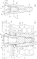
fig. 1 is a section view of part of a prosthetic dental device according to the present invention; -
fig. 2 is a section view of an intermediate connection component according to the present invention; -
fig. 3 is a section view of the prosthetic dental device according to one embodiment; -
fig. 4 is a section view of the prosthetic dental device according to another embodiment; -
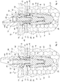
fig. 5 is a front view of the intermediate connection component connected to a first intraosseus component according to one embodiment; -
fig. 6 is a front view of the intermediate connection component connected to the first intraosseus component according to another embodiment. - To facilitate comprehension, the same reference numbers have been used, where possible, to identify identical common elements in the drawings. It is understood that elements and characteristics of one embodiment can conveniently be incorporated into other embodiments without further clarifications.
- We will now refer in detail to the various embodiments of the present invention, of which one or more examples are shown in the attached drawing. Each example is supplied by way of illustration of the invention and shall not be understood as a limitation thereof. For example, the characteristics shown or described insomuch as they are part of one embodiment can be adopted on, or in association with, other embodiments to produce another embodiment. It is understood that the present invention shall include all such modifications and variants.
- Embodiments described here using
figs. 1-6 , concern a dentalprosthetic device 10 that comprises a first component, hereafter referred to as an axialsymmetricalintraosseous implant 11 and a second component, hereinafter referred to as theabutment 12. - A first
axial cavity 24 is made in theintraosseous implant 11, open toward the outside and at least partly threaded. - The
device 10 also comprises anintermediate connection component 13, also axial-symmetric, able to be disposed between theintraosseous implant 11 and theabutment 12. - The
intermediate connection component 13 is configured to connect theintraosseous implant 11 and theabutment 12 during use. - In particular, it can be provided that the
intermediate connection component 13 is put on theintraosseous implant 11 and connected to the latter with first connection means 51. - The
abutment 12 is instead put on theintermediate connection component 13 and is connected to the latter by second connection means 52. - The
intraosseous implant 11 and theabutment 12 are therefore not in contact with each other. Theintermediate connection component 13, in fact, separates and distances theintraosseous implant 11 from theabutment 12 by a predetermined distance - The first connection means 51 and the second connection means 52 are separated and independent of each other in order to allow the selective removal/installation of the
intermediate connection component 13 and/or of theabutment 12 independently of each other. - The
intermediate connection component 13 develops axially around a central axis X (fig. 2 ). - The
intermediate connection component 13 comprises adistal part 15 in which a secondaxial cavity 32 is made, open toward the outside. Theabutment 12 is connected with the second connection means 52 in the secondaxial cavity 32. - The second
axial cavity 32 is provided with aconical part 34 and a threadedpart 33, more internal than theconical part 34. - For example, the
conical part 34 can have an angle, which defines its conicity, comprised between about 10° and about 25°. - The
intermediate connection component 13 also comprises aproximal part 14 connected by the first connection means 51 to theintraosseous implant 11. - The
proximal part 14 can be provided externally with a threadedportion 47. - According to one embodiment, the threaded
portion 33 of the secondaxial cavity 32 and the threadedportion 47 of theproximal part 14 have identical diameters of the threading. - The
proximal part 14 can also be provided with anintermediate part 16 located between thedistal part 15 and theproximal part 14. - The
intermediate part 16 is provided with at least aconical portion 18, converging toward theproximal part 14. - According to another embodiment of the invention, the
conical portion 18 of theintermediate part 16 has a conicity equal to the conicity of theconical part 34 of the secondaxial cavity 32. - According to another embodiment, the second
axial cavity 32 is also provided with aconnection part 35 interposed between the threadedpart 33 and theconical part 34. - For example, the
connection part 35 can have a polygonal cross-section shape. In this way, through theconical part 34 it is possible to insert into the connection part 35 a tool to exert a screwing force which allows to attach theintermediate connection component 13 to theintraosseous implant 11. - According to one embodiment, the
intermediate part 16 is also provided with acentral portion 17 having a surface configured to promote the regrowth of gingival and/or bone tissue. - According to one embodiment, at least the
central portion 17 and theconical portion 18 have anosteoconductive layer 48 at least partly on their most external surface. - The
osteoconductive layer 48 advantageously promotes the formation of the bone part B and of the gingival part G on the lateral walls of thedevice 10. In this way, it is possible to manage with greater certainty where the gingival connective attachment will be positioned after the healing phase. - The
osteoconductive layer 48 can be obtained by a surface treatment, for example by means of sanding treatment, plasma spray treatment, or a porous metal coating and possibly a hydroxyapatite coating, or the presence of a trabecular structure. For example, theosteoconductive layer 48 can extend for a segment comprised from about 0.5 mm to about 3 mm. - The
central portion 17 of theintermediate part 16 can have a substantially cylindrical shape. - The
intermediate part 16 of theintermediate connection component 13 can also be provided with asecond portion 19 provided between thecentral portion 17 and thedistal part 15 and having a rounded shape, flared toward theproximal part 14. - According to a preferred embodiment, a lateral wall of the second flared
portion 19 can be defined, for example, by the rotation of a curve around the central axis X. The curve can be a branch of a parabola, a hyperbola, or another conical curve. - According to one embodiment, the lateral wall of the
second portion 19 has an inclination varying from 30° to 60°, in which this variability is defined by its flared and rounded form. - The
distal part 15 of theintermediate connection component 13 has abase surface 29 which substantially determines a platform of theintermediate connection component 13. - The second
axial cavity 32 is made in thebase surface 29. - According to another embodiment, a
beveled portion 31 is made in thebase surface 29, which widens toward the inside of theintermediate connection component 13, and acylindrical portion 30 which connects to thesecond portion 19. - The
cylindrical portion 30 develops parallel to the central axis X of theintermediate connection component 13. - In this way, advantageously, the combination of the
cylindrical portion 30 and thebeveled portion 31 defines a geometric coupling between theintermediate connection component 13 and theabutment 12. - Furthermore, if the
intermediate connection component 13 is only coupled with theintraosseous implant 11, the combination of thecylindrical portion 30 and thebeveled portion 31 promotes the regeneration of the gingival part G thereon. - The
intermediate connection component 13 can comprise aclosing element 36 configured to position itself and to fit, during use, at least in theconical part 34 of the secondaxial cavity 32. - Advantageously, the closing
element 36 allows to cover the secondaxial cavity 32 while waiting for the stabilization of the assembly formed by theintermediate connection component 13 connected to theintraosseous implant 11. Furthermore, the closingelement 36 allows to provide a base for the formation of the gingival part G on it. - The
intraosseous implant 11 has a longitudinal development substantially shaped like a truncated cone - The
intraosseous implant 11 comprises astem 20 and a threading 21 which develops at least on a portion of thestem 20. Thestem 20 has acollar 22 and a pointedterminal end 23 disposed opposite thecollar 22. - The
intraosseous implant 11 is configured to be installed, or implanted, in a bone part B of a patient after a suitable seating has been made for its installation. - The threaded
portion 47 of theproximal part 14 of theintermediate connection component 13 is screwed into the firstaxial cavity 24, open toward the outside and at least partly threaded. - In this way, the threaded
portion 47 and the firstaxial cavity 24 define the first connection means 51. - In accordance with some solutions, the first
axial cavity 24 is provided with aconical wall 49 coupled with conicity to theconical portion 18 of theintermediate connection component 13. - Furthermore, according to a possible solution, the first
axial cavity 24 comprises acylindrical zone 53, located internally with respect to theconical wall 49 and in correspondence with which a coordinated cylindrical zone of theproximal part 14 of theintermediate connection component 13 is positioned. The cylindrical zone of theintermediate connection component 13 has the function of increasing the resistance of the latter and allows to correctly center and position axially theintermediate connection component 13 and theintraosseous implant 11. - In accordance with another solution, the first
axial cavity 24 comprises a threaded zone, located more internally with respect to theconical wall 49 and possibly, if present, to the cylindrical zone, and into which the threadedportion 47 of theproximal part 14 is screwed. - According to one embodiment, the
collar 22 is provided with anend surface 26 which is substantially flat and is disposed orthogonal to the longitudinal development of theintraosseous implant 11. In theend surface 26 anannular recess 27 is made, located recessed in the thickness of thestem 20. Theannular recess 27 promotes the formation of the bone part B and the stabilization of theintraosseous implant 11. - The first
axial cavity 24 is made in theend surface 26. - According to one embodiment, when connected to the
intraosseous implant 11, theintermediate connection component 13 can have a height, starting from theannular recess 27 of theintraosseous implant 11, which can be comprised between 2 mm and 6.5 mm. - According to another embodiment, the
osteoconductive layer 48 is also present on theend surface 26 which, in a connected condition of theintraosseous implant 11 and theintermediate connection component 13, determines a substantially continuousosteoconductive layer 48 with the external surface of theconical portion 18. In this way, theosteoconductive layer 48 defines the availability of a surface which further promotes the regrowth of the bone part B and its bonding with theintraosseous implant 11. - The
abutment 12 is also provided with aninternal wall 43 coupled with conicity to theconical part 34 of the secondaxial cavity 32 of theintermediate connection component 13. - The
abutment 12 is also provided with a throughcavity 44 in which a clampingscrew 37 is inserted, screwed into the threadedpart 33 of the secondaxial cavity 32 of theintermediate connection component 13. - The clamping
screw 37 and the threadedportion 33 define the second connection means 52. - Moreover, the through
cavity 44 can be provided with aconical shoulder 45 on which the head of the clampingscrew 37 is positioned resting. In this way, the clampingscrew 37, interfering with theconical shoulder 45 as it is gradually screwed to theintermediate connection component 13, thrusts theabutment 12 against theintermediate connection component 13. - The
abutment 12 has alateral surface 46 which, in the assembled condition of theabutment 12 with theintermediate connection component 13, defines a substantially continuous surface together with the lateral wall of thesecond portion 19. - Advantageously, the lack of discontinuities and edges promotes the regeneration of the gingival part G.
- According to one embodiment, the second
axial cavity 32 is configured to accommodate the clampingscrew 37. The clampingscrew 37 allows to connect and close pack-wise theintermediate connection component 13 and theabutment 12. The clampingscrew 37 has ahead 38, a threadedlower part 39 and anintermediate part 40 which connects thehead 38 to thelower part 39. - The
lower part 39 is configured to be screwed in correspondence with the threadedportion 33 of the secondaxial cavity 32 of theintermediate connection component 13. - The
abutment 12 is provided with aconnection part 41 having anannular groove 42 suitable to define a same-shape coupling with thecylindrical portion 30 and thebeveled portion 31 of theintermediate connection component 13. - The
internal wall 43 can be provided as a continuation of a more internal edge of theannular groove 42. - The presence of the
intermediate connection component 13 allows to connectabutments 12 having different characteristics of shape, to subsequently dispose the prosthesis. - According to embodiments described here, the
abutment 12 can be configured to adapt to a prosthetic dental component coaxial with respect to the central axis X (fig. 3 ), or to adapt to a prosthetic dental component inclined with respect to the central axis X (fig. 4 ). For example, it can happen that, due to requirements of space, theintraosseous implant 11 cannot be installed in a position not aligned with the installation axis of the dental prosthesis, or because of the particular conformation of the tooth that the dental prosthesis is to replace. - It is clear that modifications and/or additions of parts can be made to the
device 10 and theintermediate connection component 13 as described heretofore, without departing from the field and scope of the present invention as defined by the appended claims. - It is also clear that, although the present invention has been described with reference to some specific examples, a person of skill in the art shall certainly be able to achieve many other equivalent forms of
device 10 andintermediate connection component 13, having the characteristics as set forth in the claims and hence all coming within the field of protection defined thereby. - In the following claims, the sole purpose of the references in brackets is to facilitate reading: they must not be considered as restrictive factors with regard to the field of protection claimed in the specific claims.
Claims (11)
- Prosthetic dental device comprising:- a first axial-symmetric intraosseus component, or implant (11), in which a first axial cavity (24) is made, open toward the outside, partly threaded and provided with a conical wall (49);- a second component, or abutment (12) configured to be connected on one side to said first intraosseus component (11) and to support, on another side, a prosthetic dental component;- an axial-symmetric intermediate connection component (13) provided with a distal part (15) with a second axial cavity (32) open toward the outside, a proximal part (14) provided externally with a threaded portion (47) that, during use, is screwed into said first axial cavity (24), and an intermediate part (16) located between said distal part (15) and said proximal part (14) and provided with at least a conical portion (18), converging toward said proximal part (14) and coupled with conicity to said conical wall (49), characterized in that said second axial cavity (32) of said intermediate connection component (13) is provided with a conical part (34) and a threaded part (33) more internal with respect to the conical part (34), with a diameter of the threading equal to that of said threaded portion (47), and in that said conical portion (18) of said intermediate part (16) has a conicity equal to the conicity of said conical part (34) of said axial cavity (32).
- Device as in claim 1, characterized in that said first axial cavity (24) comprises a cylindrical zone (53), located internally with respect to the conical wall (49) and in correspondence with which a coordinated cylindrical zone of the proximal part (14) of the intermediate connection component (13) is positioned.
- Device as in claim 1 or 2, characterized in that the conical part (34) has an angle, which defines its conicity, comprised between about 10° and 25°.
- Device as in any claim hereinbefore, characterized in that said second component (12) is provided with an internal wall (43) coupled with conicity to said conical part (34), and with a through cavity (44) in which a clamping screw (37) is inserted, screwed into said threaded part (33), in order to connect said second component (12) and said intermediate connection component (13) with respect to each other.
- Device as in any claim hereinbefore, characterized in that the second axial cavity (32) is also provided with a connection part (35) interposed between the threaded part (33) and the conical part (34), and in that the connection part (35) has a polygonal cross section shape.
- Device as in any claim hereinbefore, characterized in that said first component (11) comprises a stem (20) and a threading (21) that develops at least on one portion of the stem (20), in that said stem (20) has a collar (22) and a pointed terminal end (23) opposite the collar (22).
- Device as in claim 6, characterized in that said collar (22) is provided with an end surface (26) that is substantially flat and is disposed orthogonal to the longitudinal development of the first component (11), and in that an annular recess (27) is made in the end surface (26), located recessed in the thickness of the stem (20).
- Device as in any claim hereinbefore, characterized in that said intermediate part (16) is also provided with a central portion (17) with a surface configured to promote the regrowth of gum and/or bone tissue, and with a second portion (19) provided between said central portion (17) and said distal part (15) and having a shape rounded and flared toward said proximal part (14).
- Device as in claim 8, characterized in that at least said central portion (17) and said conical portion (18) have an osteoconductive layer (48) at least partly on their more external surface.
- Axial-symmetric intermediate connection component for a prosthetic dental device comprising a first axial-symmetric intraosseus component or implant (11), and a second component, or abutment (12) configured to be connected on one side to said first intraosseus component (11) and to support, on another side, a prosthetic dental component, said intermediate connection component comprising a distal part (15), a proximal part (14) provided externally with a threaded portion (47) able to be screwed, during use, to said first intraosseus component (11), and an intermediate part (16) located between said distal part (15) and said proximal part (14) and provided with at least a conical portion (18), converging toward said proximal part (14) and coupled with conicity in a first axial cavity (24) of said first intraosseus component (11), wherein said distal part (15) comprises a second axial cavitiy (32) open toward the outside, characterized in that said second axial cavity (32) is provided with a conical part (34) and a threaded part (33) more internal with respect to the conical part (34), with a diameter of the threading equal to that of said threaded portion (47), and in that said conical portion (18) of said intermediate part (16) has a conicity equal to the conicity of said conical part (34) of said second axial cavity (32).
- Combination of a first axial-symmetric intraosseus component, or implant (11), and an axial-symmetric intermediate connection component (13), a first axial cavity (24) being made in said first axial-symmetric intraosseus component (11), open toward the outside, partly threaded and provided with a conical wall (49); and said intermediate connection portion (13) being provided with a distal part (15) with a second axial cavity (32) open toward the outside, a proximal part (14) provided externally with a threaded portion (47) that, during use, is screwed into said first axial cavity (24), and an intermediate part (16) located between said distal part (15) and said proximal part (14) and provided with at least a conical portion (18), converging toward said proximal part (14) and coupled with conicity to said conical wall (49), characterized in that said second axial cavity (32) of said intermediate connection component (13) is provided with a conical part (34) and a threaded part (33) more internal with respect to the conical part (34), with a diameter of the threading equal to that of said threaded portion (47), and in that said conical portion (18) of said intermediate part (16) has a conicity equal to the conicity of said conical part (34) of said axial cavity (32).
Applications Claiming Priority (2)
| Application Number | Priority Date | Filing Date | Title |
|---|---|---|---|
| IT102017000076961A IT201700076961A1 (en) | 2017-07-07 | 2017-07-07 | DENTAL PROSTHETIC DEVICE AND ITS INTERMEDIATE CONNECTION COMPONENT |
| PCT/IT2018/050124 WO2019008614A1 (en) | 2017-07-07 | 2018-07-06 | Dental prosthetic device and corresponding intermediate connection component |
Publications (2)
| Publication Number | Publication Date |
|---|---|
| EP3648701A1 EP3648701A1 (en) | 2020-05-13 |
| EP3648701B1 true EP3648701B1 (en) | 2021-12-08 |
Family
ID=60628029
Family Applications (1)
| Application Number | Title | Priority Date | Filing Date |
|---|---|---|---|
| EP18749575.9A Active EP3648701B1 (en) | 2017-07-07 | 2018-07-06 | Dental prosthetic device and corresponding intermediate component |
Country Status (6)
| Country | Link |
|---|---|
| US (1) | US11564780B2 (en) |
| EP (1) | EP3648701B1 (en) |
| CN (1) | CN111356415A (en) |
| ES (1) | ES2908272T3 (en) |
| IT (1) | IT201700076961A1 (en) |
| WO (1) | WO2019008614A1 (en) |
Families Citing this family (4)
| Publication number | Priority date | Publication date | Assignee | Title |
|---|---|---|---|---|
| IT202200000866A1 (en) * | 2022-01-20 | 2023-07-20 | Eptamed Srl | Kit for dental implant, endosseous portion of dental implant, screwing abutment, closing abutment, transmucosal healing abutment, prosthetic abutment and impression abutment |
| IT202300000354A1 (en) * | 2023-01-12 | 2024-07-12 | Univ Degli Studi Roma La Sapienza | IMPLANT ABUTMENT |
| EP4431054B1 (en) * | 2023-03-15 | 2026-04-22 | Talladium España, S.L. | Internal transepthelial abutment |
| FR3156305B1 (en) * | 2023-12-06 | 2026-03-06 | Robert Fromental | Dental implant with enhanced osseointegration |
Family Cites Families (12)
| Publication number | Priority date | Publication date | Assignee | Title |
|---|---|---|---|---|
| US5030095A (en) * | 1989-08-16 | 1991-07-09 | Niznick Gerald A | Angled abutment for endosseous implants |
| EP0629384B1 (en) * | 1993-06-14 | 1996-11-27 | Institut Straumann Ag | Device for fixing a dental prosthesis to a jaw bone |
| WO2008138852A1 (en) * | 2007-05-11 | 2008-11-20 | Biomain Ab | Implant arrangement |
| JP6033776B2 (en) * | 2010-09-24 | 2016-11-30 | ジンマー デンタル,インコーポレイティド | Dental implant and abutment system |
| JP5761342B2 (en) * | 2011-05-25 | 2015-08-12 | 日立金属株式会社 | Implant keeper and assembly thereof, and method of fixing keeper |
| EP2653131B1 (en) * | 2012-04-19 | 2018-02-28 | Dentsply IH AB | A dental implant set |
| EP3821847B1 (en) * | 2013-03-15 | 2024-03-27 | Zimmer Dental Inc. | Dental implant with improved prosthetic interface |
| CH708896A2 (en) * | 2013-11-27 | 2015-05-29 | Systems Schweiz Ag Z | Dental implant system with a ceramic implant. |
| KR101684019B1 (en) * | 2014-12-15 | 2016-12-08 | 장재우 | dental implant unit |
| US10426580B2 (en) * | 2015-01-21 | 2019-10-01 | Kwang Seob Kim | Implant unit |
| IL242816B (en) * | 2015-11-26 | 2020-06-30 | Mis Implants Tech Ltd | Abutment, coping and method of connecting thereof in a dental multi-unit system |
| CN106109036A (en) * | 2016-08-30 | 2016-11-16 | 江苏创英医疗器械有限公司 | Tooth implant |
-
2017
- 2017-07-07 IT IT102017000076961A patent/IT201700076961A1/en unknown
-
2018
- 2018-07-06 CN CN201880057284.4A patent/CN111356415A/en active Pending
- 2018-07-06 EP EP18749575.9A patent/EP3648701B1/en active Active
- 2018-07-06 ES ES18749575T patent/ES2908272T3/en active Active
- 2018-07-06 WO PCT/IT2018/050124 patent/WO2019008614A1/en not_active Ceased
- 2018-07-06 US US16/628,804 patent/US11564780B2/en active Active
Also Published As
| Publication number | Publication date |
|---|---|
| US20200197135A1 (en) | 2020-06-25 |
| ES2908272T3 (en) | 2022-04-28 |
| CN111356415A (en) | 2020-06-30 |
| IT201700076961A1 (en) | 2019-01-07 |
| US11564780B2 (en) | 2023-01-31 |
| WO2019008614A1 (en) | 2019-01-10 |
| EP3648701A1 (en) | 2020-05-13 |
Similar Documents
| Publication | Publication Date | Title |
|---|---|---|
| US11564780B2 (en) | Dental prosthetic device and corresponding intermediate connection component | |
| US7309231B2 (en) | Implant | |
| US5989028A (en) | Non-submergible, one-part, root-form endosseous dental implants | |
| US6120292A (en) | Healing cap for dental implants | |
| EP1531753B1 (en) | Prosthetic mounting device | |
| US8197255B2 (en) | Condensing skeletal implant that facilitate insertions | |
| US5052931A (en) | Enossal implant | |
| US20060003290A1 (en) | Endosseous one-piece screw-type dental implants | |
| US20060008763A1 (en) | Device and arrangement for fixture installation | |
| JP2003518980A (en) | Intraosseous dental implants and combination structures | |
| JPH06205795A (en) | Anchor element for fixation in bone tissue | |
| JPH0334732B2 (en) | ||
| US20090291412A1 (en) | Dental implant, abutment structure and method for implanting a dental implant | |
| AU2002249391A1 (en) | Implant | |
| SE512050C2 (en) | Rotationally symmetrical leg anchoring element | |
| JP2003530951A (en) | Implant | |
| US20060127849A1 (en) | Dental implant system | |
| US5549475A (en) | Enossal single-tooth implant | |
| US20150018890A1 (en) | Screw implant with replacement head for height adjustment and simplified storage | |
| JP6639286B2 (en) | Numerous dentures fixed through | |
| EP3641694B1 (en) | Intraosseous dental implant | |
| KR20020070119A (en) | Artificial tooth root | |
| US20090155743A1 (en) | Improved Dental Implant | |
| KR20010020310A (en) | Conical implant | |
| US20110229855A1 (en) | Dental prosthesis |
Legal Events
| Date | Code | Title | Description |
|---|---|---|---|
| STAA | Information on the status of an ep patent application or granted ep patent |
Free format text: STATUS: UNKNOWN |
|
| STAA | Information on the status of an ep patent application or granted ep patent |
Free format text: STATUS: THE INTERNATIONAL PUBLICATION HAS BEEN MADE |
|
| PUAI | Public reference made under article 153(3) epc to a published international application that has entered the european phase |
Free format text: ORIGINAL CODE: 0009012 |
|
| STAA | Information on the status of an ep patent application or granted ep patent |
Free format text: STATUS: REQUEST FOR EXAMINATION WAS MADE |
|
| 17P | Request for examination filed |
Effective date: 20200116 |
|
| AK | Designated contracting states |
Kind code of ref document: A1 Designated state(s): AL AT BE BG CH CY CZ DE DK EE ES FI FR GB GR HR HU IE IS IT LI LT LU LV MC MK MT NL NO PL PT RO RS SE SI SK SM TR |
|
| AX | Request for extension of the european patent |
Extension state: BA ME |
|
| DAV | Request for validation of the european patent (deleted) | ||
| DAX | Request for extension of the european patent (deleted) | ||
| GRAP | Despatch of communication of intention to grant a patent |
Free format text: ORIGINAL CODE: EPIDOSNIGR1 |
|
| STAA | Information on the status of an ep patent application or granted ep patent |
Free format text: STATUS: GRANT OF PATENT IS INTENDED |
|
| INTG | Intention to grant announced |
Effective date: 20210722 |
|
| GRAS | Grant fee paid |
Free format text: ORIGINAL CODE: EPIDOSNIGR3 |
|
| GRAA | (expected) grant |
Free format text: ORIGINAL CODE: 0009210 |
|
| STAA | Information on the status of an ep patent application or granted ep patent |
Free format text: STATUS: THE PATENT HAS BEEN GRANTED |
|
| AK | Designated contracting states |
Kind code of ref document: B1 Designated state(s): AL AT BE BG CH CY CZ DE DK EE ES FI FR GB GR HR HU IE IS IT LI LT LU LV MC MK MT NL NO PL PT RO RS SE SI SK SM TR |
|
| REG | Reference to a national code |
Ref country code: GB Ref legal event code: FG4D |
|
| REG | Reference to a national code |
Ref country code: AT Ref legal event code: REF Ref document number: 1453179 Country of ref document: AT Kind code of ref document: T Effective date: 20211215 Ref country code: CH Ref legal event code: EP |
|
| REG | Reference to a national code |
Ref country code: DE Ref legal event code: R096 Ref document number: 602018027888 Country of ref document: DE |
|
| REG | Reference to a national code |
Ref country code: IE Ref legal event code: FG4D |
|
| REG | Reference to a national code |
Ref country code: LT Ref legal event code: MG9D |
|
| REG | Reference to a national code |
Ref country code: NL Ref legal event code: MP Effective date: 20211208 |
|
| REG | Reference to a national code |
Ref country code: ES Ref legal event code: FG2A Ref document number: 2908272 Country of ref document: ES Kind code of ref document: T3 Effective date: 20220428 |
|
| PG25 | Lapsed in a contracting state [announced via postgrant information from national office to epo] |
Ref country code: RS Free format text: LAPSE BECAUSE OF FAILURE TO SUBMIT A TRANSLATION OF THE DESCRIPTION OR TO PAY THE FEE WITHIN THE PRESCRIBED TIME-LIMIT Effective date: 20211208 Ref country code: LT Free format text: LAPSE BECAUSE OF FAILURE TO SUBMIT A TRANSLATION OF THE DESCRIPTION OR TO PAY THE FEE WITHIN THE PRESCRIBED TIME-LIMIT Effective date: 20211208 Ref country code: FI Free format text: LAPSE BECAUSE OF FAILURE TO SUBMIT A TRANSLATION OF THE DESCRIPTION OR TO PAY THE FEE WITHIN THE PRESCRIBED TIME-LIMIT Effective date: 20211208 Ref country code: BG Free format text: LAPSE BECAUSE OF FAILURE TO SUBMIT A TRANSLATION OF THE DESCRIPTION OR TO PAY THE FEE WITHIN THE PRESCRIBED TIME-LIMIT Effective date: 20220308 |
|
| REG | Reference to a national code |
Ref country code: AT Ref legal event code: MK05 Ref document number: 1453179 Country of ref document: AT Kind code of ref document: T Effective date: 20211208 |
|
| PG25 | Lapsed in a contracting state [announced via postgrant information from national office to epo] |
Ref country code: SE Free format text: LAPSE BECAUSE OF FAILURE TO SUBMIT A TRANSLATION OF THE DESCRIPTION OR TO PAY THE FEE WITHIN THE PRESCRIBED TIME-LIMIT Effective date: 20211208 Ref country code: NO Free format text: LAPSE BECAUSE OF FAILURE TO SUBMIT A TRANSLATION OF THE DESCRIPTION OR TO PAY THE FEE WITHIN THE PRESCRIBED TIME-LIMIT Effective date: 20220308 Ref country code: LV Free format text: LAPSE BECAUSE OF FAILURE TO SUBMIT A TRANSLATION OF THE DESCRIPTION OR TO PAY THE FEE WITHIN THE PRESCRIBED TIME-LIMIT Effective date: 20211208 Ref country code: HR Free format text: LAPSE BECAUSE OF FAILURE TO SUBMIT A TRANSLATION OF THE DESCRIPTION OR TO PAY THE FEE WITHIN THE PRESCRIBED TIME-LIMIT Effective date: 20211208 Ref country code: GR Free format text: LAPSE BECAUSE OF FAILURE TO SUBMIT A TRANSLATION OF THE DESCRIPTION OR TO PAY THE FEE WITHIN THE PRESCRIBED TIME-LIMIT Effective date: 20220309 |
|
| PG25 | Lapsed in a contracting state [announced via postgrant information from national office to epo] |
Ref country code: NL Free format text: LAPSE BECAUSE OF FAILURE TO SUBMIT A TRANSLATION OF THE DESCRIPTION OR TO PAY THE FEE WITHIN THE PRESCRIBED TIME-LIMIT Effective date: 20211208 |
|
| PG25 | Lapsed in a contracting state [announced via postgrant information from national office to epo] |
Ref country code: SM Free format text: LAPSE BECAUSE OF FAILURE TO SUBMIT A TRANSLATION OF THE DESCRIPTION OR TO PAY THE FEE WITHIN THE PRESCRIBED TIME-LIMIT Effective date: 20211208 Ref country code: SK Free format text: LAPSE BECAUSE OF FAILURE TO SUBMIT A TRANSLATION OF THE DESCRIPTION OR TO PAY THE FEE WITHIN THE PRESCRIBED TIME-LIMIT Effective date: 20211208 Ref country code: RO Free format text: LAPSE BECAUSE OF FAILURE TO SUBMIT A TRANSLATION OF THE DESCRIPTION OR TO PAY THE FEE WITHIN THE PRESCRIBED TIME-LIMIT Effective date: 20211208 Ref country code: PT Free format text: LAPSE BECAUSE OF FAILURE TO SUBMIT A TRANSLATION OF THE DESCRIPTION OR TO PAY THE FEE WITHIN THE PRESCRIBED TIME-LIMIT Effective date: 20220408 Ref country code: EE Free format text: LAPSE BECAUSE OF FAILURE TO SUBMIT A TRANSLATION OF THE DESCRIPTION OR TO PAY THE FEE WITHIN THE PRESCRIBED TIME-LIMIT Effective date: 20211208 Ref country code: CZ Free format text: LAPSE BECAUSE OF FAILURE TO SUBMIT A TRANSLATION OF THE DESCRIPTION OR TO PAY THE FEE WITHIN THE PRESCRIBED TIME-LIMIT Effective date: 20211208 |
|
| PG25 | Lapsed in a contracting state [announced via postgrant information from national office to epo] |
Ref country code: PL Free format text: LAPSE BECAUSE OF FAILURE TO SUBMIT A TRANSLATION OF THE DESCRIPTION OR TO PAY THE FEE WITHIN THE PRESCRIBED TIME-LIMIT Effective date: 20211208 Ref country code: AT Free format text: LAPSE BECAUSE OF FAILURE TO SUBMIT A TRANSLATION OF THE DESCRIPTION OR TO PAY THE FEE WITHIN THE PRESCRIBED TIME-LIMIT Effective date: 20211208 |
|
| REG | Reference to a national code |
Ref country code: DE Ref legal event code: R097 Ref document number: 602018027888 Country of ref document: DE |
|
| PG25 | Lapsed in a contracting state [announced via postgrant information from national office to epo] |
Ref country code: IS Free format text: LAPSE BECAUSE OF FAILURE TO SUBMIT A TRANSLATION OF THE DESCRIPTION OR TO PAY THE FEE WITHIN THE PRESCRIBED TIME-LIMIT Effective date: 20220408 |
|
| PLBE | No opposition filed within time limit |
Free format text: ORIGINAL CODE: 0009261 |
|
| STAA | Information on the status of an ep patent application or granted ep patent |
Free format text: STATUS: NO OPPOSITION FILED WITHIN TIME LIMIT |
|
| PG25 | Lapsed in a contracting state [announced via postgrant information from national office to epo] |
Ref country code: DK Free format text: LAPSE BECAUSE OF FAILURE TO SUBMIT A TRANSLATION OF THE DESCRIPTION OR TO PAY THE FEE WITHIN THE PRESCRIBED TIME-LIMIT Effective date: 20211208 Ref country code: AL Free format text: LAPSE BECAUSE OF FAILURE TO SUBMIT A TRANSLATION OF THE DESCRIPTION OR TO PAY THE FEE WITHIN THE PRESCRIBED TIME-LIMIT Effective date: 20211208 |
|
| 26N | No opposition filed |
Effective date: 20220909 |
|
| PG25 | Lapsed in a contracting state [announced via postgrant information from national office to epo] |
Ref country code: SI Free format text: LAPSE BECAUSE OF FAILURE TO SUBMIT A TRANSLATION OF THE DESCRIPTION OR TO PAY THE FEE WITHIN THE PRESCRIBED TIME-LIMIT Effective date: 20211208 |
|
| P01 | Opt-out of the competence of the unified patent court (upc) registered |
Effective date: 20230524 |
|
| PG25 | Lapsed in a contracting state [announced via postgrant information from national office to epo] |
Ref country code: HU Free format text: LAPSE BECAUSE OF FAILURE TO SUBMIT A TRANSLATION OF THE DESCRIPTION OR TO PAY THE FEE WITHIN THE PRESCRIBED TIME-LIMIT; INVALID AB INITIO Effective date: 20180706 |
|
| PG25 | Lapsed in a contracting state [announced via postgrant information from national office to epo] |
Ref country code: MK Free format text: LAPSE BECAUSE OF FAILURE TO SUBMIT A TRANSLATION OF THE DESCRIPTION OR TO PAY THE FEE WITHIN THE PRESCRIBED TIME-LIMIT Effective date: 20211208 Ref country code: CY Free format text: LAPSE BECAUSE OF FAILURE TO SUBMIT A TRANSLATION OF THE DESCRIPTION OR TO PAY THE FEE WITHIN THE PRESCRIBED TIME-LIMIT Effective date: 20211208 |
|
| PG25 | Lapsed in a contracting state [announced via postgrant information from national office to epo] |
Ref country code: MT Free format text: LAPSE BECAUSE OF FAILURE TO SUBMIT A TRANSLATION OF THE DESCRIPTION OR TO PAY THE FEE WITHIN THE PRESCRIBED TIME-LIMIT Effective date: 20211208 |
|
| PGFP | Annual fee paid to national office [announced via postgrant information from national office to epo] |
Ref country code: TR Payment date: 20250617 Year of fee payment: 8 |
|
| PGFP | Annual fee paid to national office [announced via postgrant information from national office to epo] |
Ref country code: LU Payment date: 20250724 Year of fee payment: 8 |
|
| PGFP | Annual fee paid to national office [announced via postgrant information from national office to epo] |
Ref country code: ES Payment date: 20250815 Year of fee payment: 8 |
|
| PGFP | Annual fee paid to national office [announced via postgrant information from national office to epo] |
Ref country code: DE Payment date: 20250728 Year of fee payment: 8 |
|
| PGFP | Annual fee paid to national office [announced via postgrant information from national office to epo] |
Ref country code: MC Payment date: 20250721 Year of fee payment: 8 |
|
| PGFP | Annual fee paid to national office [announced via postgrant information from national office to epo] |
Ref country code: IT Payment date: 20250708 Year of fee payment: 8 |
|
| PGFP | Annual fee paid to national office [announced via postgrant information from national office to epo] |
Ref country code: BE Payment date: 20250724 Year of fee payment: 8 Ref country code: GB Payment date: 20250722 Year of fee payment: 8 |
|
| PGFP | Annual fee paid to national office [announced via postgrant information from national office to epo] |
Ref country code: FR Payment date: 20250723 Year of fee payment: 8 |
|
| PGFP | Annual fee paid to national office [announced via postgrant information from national office to epo] |
Ref country code: CH Payment date: 20250801 Year of fee payment: 8 |
|
| PGFP | Annual fee paid to national office [announced via postgrant information from national office to epo] |
Ref country code: IE Payment date: 20250718 Year of fee payment: 8 |