EP3648653B1 - Direct visualization catheter and system - Google Patents
Direct visualization catheter and system Download PDFInfo
- Publication number
- EP3648653B1 EP3648653B1 EP18804455.6A EP18804455A EP3648653B1 EP 3648653 B1 EP3648653 B1 EP 3648653B1 EP 18804455 A EP18804455 A EP 18804455A EP 3648653 B1 EP3648653 B1 EP 3648653B1
- Authority
- EP
- European Patent Office
- Prior art keywords
- camera
- elongate shaft
- distal end
- direct visualization
- hinge
- Prior art date
- Legal status (The legal status is an assumption and is not a legal conclusion. Google has not performed a legal analysis and makes no representation as to the accuracy of the status listed.)
- Active
Links
Images






Classifications
-
- A—HUMAN NECESSITIES
- A61—MEDICAL OR VETERINARY SCIENCE; HYGIENE
- A61B—DIAGNOSIS; SURGERY; IDENTIFICATION
- A61B1/00—Instruments for performing medical examinations of the interior of cavities or tubes of the body by visual or photographical inspection, e.g. endoscopes; Illuminating arrangements therefor
- A61B1/00064—Constructional details of the endoscope body
- A61B1/00071—Insertion part of the endoscope body
- A61B1/0008—Insertion part of the endoscope body characterised by distal tip features
- A61B1/00082—Balloons
-
- A—HUMAN NECESSITIES
- A61—MEDICAL OR VETERINARY SCIENCE; HYGIENE
- A61B—DIAGNOSIS; SURGERY; IDENTIFICATION
- A61B1/00—Instruments for performing medical examinations of the interior of cavities or tubes of the body by visual or photographical inspection, e.g. endoscopes; Illuminating arrangements therefor
- A61B1/00163—Optical arrangements
- A61B1/00174—Optical arrangements characterised by the viewing angles
- A61B1/00183—Optical arrangements characterised by the viewing angles for variable viewing angles
-
- A—HUMAN NECESSITIES
- A61—MEDICAL OR VETERINARY SCIENCE; HYGIENE
- A61B—DIAGNOSIS; SURGERY; IDENTIFICATION
- A61B1/00—Instruments for performing medical examinations of the interior of cavities or tubes of the body by visual or photographical inspection, e.g. endoscopes; Illuminating arrangements therefor
- A61B1/04—Instruments for performing medical examinations of the interior of cavities or tubes of the body by visual or photographical inspection, e.g. endoscopes; Illuminating arrangements therefor combined with photographic or television appliances
- A61B1/05—Instruments for performing medical examinations of the interior of cavities or tubes of the body by visual or photographical inspection, e.g. endoscopes; Illuminating arrangements therefor combined with photographic or television appliances characterised by the image sensor, e.g. camera, being in the distal end portion
-
- A—HUMAN NECESSITIES
- A61—MEDICAL OR VETERINARY SCIENCE; HYGIENE
- A61B—DIAGNOSIS; SURGERY; IDENTIFICATION
- A61B1/00—Instruments for performing medical examinations of the interior of cavities or tubes of the body by visual or photographical inspection, e.g. endoscopes; Illuminating arrangements therefor
- A61B1/04—Instruments for performing medical examinations of the interior of cavities or tubes of the body by visual or photographical inspection, e.g. endoscopes; Illuminating arrangements therefor combined with photographic or television appliances
- A61B1/05—Instruments for performing medical examinations of the interior of cavities or tubes of the body by visual or photographical inspection, e.g. endoscopes; Illuminating arrangements therefor combined with photographic or television appliances characterised by the image sensor, e.g. camera, being in the distal end portion
- A61B1/051—Details of CCD assembly
-
- A—HUMAN NECESSITIES
- A61—MEDICAL OR VETERINARY SCIENCE; HYGIENE
- A61B—DIAGNOSIS; SURGERY; IDENTIFICATION
- A61B1/00—Instruments for performing medical examinations of the interior of cavities or tubes of the body by visual or photographical inspection, e.g. endoscopes; Illuminating arrangements therefor
- A61B1/06—Instruments for performing medical examinations of the interior of cavities or tubes of the body by visual or photographical inspection, e.g. endoscopes; Illuminating arrangements therefor with illuminating arrangements
-
- A—HUMAN NECESSITIES
- A61—MEDICAL OR VETERINARY SCIENCE; HYGIENE
- A61B—DIAGNOSIS; SURGERY; IDENTIFICATION
- A61B1/00—Instruments for performing medical examinations of the interior of cavities or tubes of the body by visual or photographical inspection, e.g. endoscopes; Illuminating arrangements therefor
- A61B1/012—Instruments for performing medical examinations of the interior of cavities or tubes of the body by visual or photographical inspection, e.g. endoscopes; Illuminating arrangements therefor characterised by internal passages or accessories therefor
- A61B1/018—Instruments for performing medical examinations of the interior of cavities or tubes of the body by visual or photographical inspection, e.g. endoscopes; Illuminating arrangements therefor characterised by internal passages or accessories therefor for receiving instruments
Definitions
- the present disclosure relates to medical devices for direct visualization within a body. More specifically, the disclosure relates to catheters and systems for direct visualization within a blood pool in a minimally-invasive manner.
- Direct visualization of tissues within a patient can provide important information and guidance in the diagnosis and treatment of illnesses. With respect to heart diseases, direct visualization can be helpful, for example, in the diagnosis and treatment heart valve diseases, among other diseases. In vivo images provided by direct visualization can allow for a thorough inspection of tissues with higher resolution than other techniques, such as ultrasound. Procedures, such as a septal cross, mitral valve repair, and stitching of a valve annulus can all benefit from the accuracy provided by direct visualization.
- Direct visualization within the heart is challenging because the general opacity of blood can obscure the tissues to be viewed.
- Some direct visualization catheters employ a transparent balloon at the end of the catheter to displace blood adjacent to the tissues to be viewed.
- the balloon can be filled with saline and provide an optical lensing effect, further clarifying the view of a camera within the balloon at the end of the catheter.
- Publication US 2017/296795 A1 discloses a device with the features of the preamble of claim 1.
- An embodiment of the present invention is a direct visualization catheter including a handle, a balloon, an elongate shaft, and a camera assembly.
- the elongate shaft has a proximal end and a distal end opposite the proximal end.
- the proximal end is coupled to the handle.
- the distal end is coupled to the balloon and defines a longitudinal axis.
- the camera assembly is coupled to the distal end of the elongate shaft and is disposed within the balloon.
- the camera assembly includes a camera and an adjustment mechanism for varying a configuration of the camera relative to the distal end of the elongate shaft between a delivery configuration and a deployed configuration.
- the camera faces primarily in a radial direction in the delivery configuration and the camera faces primarily in an axial direction in the deployed configuration.
- Balloon catheters and systems and methods in accordance with embodiments of this disclosure can provide for direct visualization within a blood pool in a minimally-invasive manner.
- an articulating camera disposed within a balloon at a distal end of a catheter can be configured for a low-profile delivery to the direct visualization site within the patient, and then the camera can be hinged away from the catheter in a deployed configuration. In the delivery configuration, the camera faces primarily in a radial direction. In the deployed configuration, the camera faces primarily in an axial direction for effective viewing.
- Such direct visualization catheters can have a smaller diameter during delivery.
- a smaller diameter catheter may cause less distress to the patient when, for example, passing the catheter through the septum, from the right side of the heart to the left side of the heart. It is believed that causing less distress from the passing of the catheter through the septum may result in better patient outcomes.
- An articulating camera disposed within a balloon at a distal end of a catheter can be aimed with an adjustment mechanism as described herein to vary a viewing direction observed by the camera relative to the catheter.
- an adjustment mechanism as described herein to vary a viewing direction observed by the camera relative to the catheter.
- FIG. 1 is a schematic view illustrating in use of a system for direct visualization within a patient's heart, in accordance with embodiments of this disclosure.
- FIG. 1 illustrates a patient 10 including a heart 12 and a system 14 for direct visualization inserted into a right atrium 16 of the heart 12 for direct visualization of a tricuspid valve 18.
- the system 14 can include an image processing device 20 and a direct visualization catheter 22.
- the image processing device 20 can include functionality for display of images, storage of images, and/or analysis of images.
- the catheter 22 can include a handle 24, a balloon 26, and an elongate shaft 28.
- the handle 24 can include an actuator 30 and a plurality of lumens (not shown).
- the balloon 26 can be formed of a transparent material and be a transparent balloon.
- the balloon 26 can include a balloon lumen 32, as shown in FIG. 1 .
- the elongate shaft 28 can be formed of a flexible, biocompatible polymer, such as, for example, silicone, polyisobutylene polyurethane, nylon, polyimide, polyetheretherketone, or a polyether block amide, such as Pebax ® or Vestamid ® .
- the elongate shaft 28 can include a proximal end 34 and a distal end 36 opposite the proximal end 34.
- the elongate shaft 28 can include a plurality of lumens (not shown) extending from the proximal end 34 to the distal end 36.
- the actuator 30 can be, for example, and without limitation, a position switch, a pressure regulating device, a voltage regulating device, or a lever or joy stick.
- the catheter 22 can be electrically connected to the image processing device 20 by electrical lines 38.
- the proximal end 34 of the elongate shaft 28 can be coupled to the handle 24 with at least one of the plurality of lumens in the elongate shaft 28 connected with at least one of the plurality of lumens in the handle 24 to form a continuous lumen.
- the distal end 36 of the elongate shaft 28 is coupled to the balloon 26 with the balloon lumen 32 connected with at least one of the plurality of lumens in the elongate shaft 28. So arranged, it is possible to pass devices, for example, a SpyBite ® Biopsy Forceps from Boston Scientific Corporation, Natick, Massachusetts, from the handle 24, through the elongate shaft 28, and out through the balloon 26.
- the actuator 30 on the handle 24 can adjust a viewing direction of an articulating camera assembly 40, not shown in FIG. 1 , but describe in embodiments below.
- the articulating camera assembly 40 can be coupled to the distal end 36 of the elongate shaft 28.
- the articulating camera assembly 40 can be disposed within the balloon 26.
- the balloon 26 can be filled with a biocompatible, transparent fluid, such as saline solution, to displace blood adjacent to the tissues to be viewed.
- the transparent fluid can provide an optical lensing effect, further clarifying the view of the articulating camera assembly 40.
- Image output signals from the articulating camera assembly 40 can be sent to the image processing device 20 over the electrical lines 38.
- the electrical lines 38 can also supply power from the image processing device 20 to the articulating camera assembly 40.
- the electrical lines 38 can also connect to a separate power source to supply power to the articulating camera assembly 40.
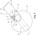
- FIG. 2 is a perspective schematic view of the distal end 36 of the direct visualization catheter 22, in accordance with some embodiments of this disclosure.
- the distal end 36 can define a longitudinal axis A.
- the elongate shaft 28 can further include a cap 42 at the distal end 36, as shown in FIG. 2 .
- the cap 42 can be formed of a variety of biocompatible materials that are typically harder than the flexible polymer of rest of the elongate shaft 28.
- Suitable materials for the cap 42 can include, for example, stainless steel, nickel-titanium alloys, MP35N ® , Elgiloy ® , and polymers such as polyetheretherketone, polyvinyl chloride, perfluoroalkoxy, polycarbonate, polyimide, polyethylene terephthalate, and polyetherimide.
- the cap 42 can include a slot 44, and plurality of lumens, such as delivery lumen 46, and at least one lighting lumen 48 (two shown) that align with corresponding lumens in the rest of the elongate shaft 28.
- the delivery lumen 46 is one of the plurality of lumens that extends from the distal end 36, through the elongate shaft 28, and into the handle 24.
- the delivery lumen 46 can be used to pass devices from the handle 24, through the elongate shaft 28, and out through the balloon lumen 32.
- the devices passed through the catheter 22 can penetrate the balloon 26.
- the balloon lumen 32 is omitted from FIGS. 3A, 3B , 4A, 4B , 5A, 5B , 6A, 6B , 7A, 7B , 8A, 8B , 9A, 9B , and 11A, 11B .
- all embodiments may include the balloon lumen 32.
- the lighting lumen 48 can include a lighting device 50 (two shown).
- the lighting device 50 can include, for example and without limitation, a fiber optic cable or a light emitting diode.
- the lighting device 50 provides illumination for the articulating camera assembly 40.
- the balloon 26 can be attached around a circumference of the elongate shaft 28 by, for example, an adhesive.
- the balloon 26 can be attached to either or both of the cap 42 or a portion of the elongate shaft 28 adjacent to the cap 42.
- the articulating camera assembly 40 can be disposed within the slot 44 to couple it to the distal end 36.
- FIGS. 3A and 3B are side cross-sectional views of the distal end 36 of the direct visualization catheter 22 of FIG. 2 , in accordance with embodiments of this disclosure.
- FIG. 3A shows the catheter 22 with the articulating camera assembly 40 in a delivery configuration.
- FIG. 3B shows the catheter 22 with the articulating camera assembly 40 in a deployed configuration.
- the articulating camera assembly 40 includes a camera 52 and an adjustment mechanism 54.
- the adjustment mechanism 54 can vary the direction faced by the camera 52 relative to the longitudinal axis A.
- the adjustment mechanism 54 includes a hinge 56, a biasing element 58, and a control element 60.
- the plurality of lumens of the elongate shaft 28 can further include an inflation lumen 62 and a camera lumen 64.
- the inflation lumen 62 can extend to the handle 24 and on to a pressurized source of saline for inflation of the balloon 26 once the catheter 22 is positioned for viewing the heart 12 in the patient 10 ( FIG. 1 ).
- the camera 52 can include any type of solid state image sensor known in the art, for example and without limitation, a complementary metal-oxide-semiconductor (CMOS) image sensor or a charge-coupled device (CCD) image sensor.
- CMOS complementary metal-oxide-semiconductor
- CCD charge-coupled device
- the image sensor can be encased within a protective frame (not shown).
- the camera 52 can be relatively thin but with a relatively large image sensing area. That is, the camera 52 can be shaped like a plate with the image sensing area on a large side of the plate. The relatively large image sensing area can provide good quality imaging.
- the hinge 56 is configured to permit the camera 52 to move relative to the distal end 36 of the elongate shaft 28.
- the hinge 56 can be a multipart hinge including a hinge pin as is known in the art.
- the hinge can be formed of a biocompatible metal, such as stainless steel, or a biocompatible polymer, such as PEEK.
- One part of the hinge 56 can be coupled to the frame of the camera 52, while another part is coupled to a radially outward facing surface of the slot 44 to couple the camera 52 to the elongate shaft 28, as shown in FIG. 3A .
- the hinge 56 permits movement of the camera 52 relative to the distal end 36 of the elongate shaft 28 about an axis defined by the hinge pin.
- the hinge 56 can include a hinge pin that extends through holes in the frame of the camera 52, the holes sized to permit free rotation of the frame relative to the pin.
- the pin can be formed of a biocompatible metal, such as stainless steel, or a biocompatible polymer, such as PEEK.
- the pin can be coupled on either end to opposite sidewalls of the slot 44 to connect the camera 52 to the elongate shaft 28 to permit movement of the camera 52 relative to the distal end 36 of the elongate shaft 28 about the hinge 56.
- the biasing element 58 can be formed of any type of biocompatible elastic material, for example, and without limitation, nitinol, spring steel alloys (medical grade), and polymers, such as polyethylene terephthalate (e.g. Mylar ® ), poly(p-xylylene), Kevlar ® , ultra-high-molecular-weight polyethylene, or nylon.
- the biasing element 58 can be configured as, for example, a helical coil spring, a leaf spring, or an elastic band.
- the biasing element 58 is configured with respect to the hinge 56 to provide a first force to maintain the hinge 56 in a fixed position in the absence of other forces.
- the hinge 56 and the biasing element 58 can be integrated.
- the hinge 56 can be in the form of a single L-shaped piece of biocompatible elastic material, such as those described above, thus integrating the hinge 56 and the biasing element 58.
- the first force of the elastic material can maintain the hinge 56/biasing element 58 in the L-shape in the absence of other forces.
- the control element 60 is configured to selectively apply a second force to the hinge 56 or to the camera 52 opposite the first force to counter the first force of the biasing element 58 and cause movement of the camera 52 relative to the distal end 36 of the elongate shaft 28.
- the control element 60 includes an actuation thread coupled to the camera 52, as shown in FIG. 3A .
- the actuation thread is flexible and can be formed of, for example, a metal wire or a polymer thread made of, for example, Kevlar ® , graphene, or nylon.
- the control element 60 can extend from the camera 52, through the camera lumen 64, and at least to the proximal end 34 of the elongate shaft 28. In the embodiment of FIG.
- the control element 60 extends to the actuator 30 on the handle 24 ( FIG. 1 ).
- the actuator 30 can be a position switch that pulls on the control element 60 (actuation thread) to various extents depending on the position of the position switch.
- the control element 60 (actuation thread) physically connects the actuator 30 (position switch) to the camera 52.
- the electrical lines 38 can extend from the camera 52, through the camera lumen 64, to the image processing device 20, as described above, to electrically connect the camera 52 to the image processing device 20.
- the hinge 56 can be a conductive hinge that includes a plurality of electrical conductors configured to electrically connect the electrical lines 38 to the camera 52.
- FIG. 3A shows the catheter 22 with the first force from the biasing element 58 applied to the hinge 56 and without the second force from the control element 60 being applied to the camera 52 so that the camera 52 faces in a primarily radial direction.
- the camera 52 faces in a primarily radial direction when it faces more in a radial direction relative to the longitudinal axis than in an axial direction relative to the longitudinal axis A.
- the camera 52 faces in a viewing direction V1.
- the viewing direction V1 is a completely radial inward direction toward the longitudinal axis A and does not face at all in the axial direction. So configured, the camera 52 has a low profile and does not extend beyond a diameter D1 of the elongate shaft 28.
- the camera 52 presents a small profile in the axial direction.
- a 4 mm diameter (12 French) catheter is necessary to provide enough axially-facing space to accommodate the axially-facing camera and a 2.2 mm - 2.5 mm diameter (7 French) delivery lumen.
- the diameter D1 of the elongate shaft 28 can be from 3.1 mm to 3.5 mm (10 French) while maintaining the lumen diameter D2 of the delivery lumen 46 at 2.2 mm to 2.5 mm.
- the articulated camera assembly 40 can be deployed, as shown in FIG. 3B .
- the second force is applied to the camera 52 by moving the actuator 30 ( FIG.1 ) to pull the control element 60 (actuation thread). Pulling the control element 60 moves the camera 52 about the hinge 56 and against the biasing element 58 so that the camera 52 faces in a primarily axial direction.
- the camera 52 faces in a primarily axial direction when it faces more in the axial direction relative to the longitudinal axis than in the radial direction relative to the longitudinal axis A.
- FIG. 1 the second force is applied to the camera 52 by moving the actuator 30 ( FIG.1 ) to pull the control element 60 (actuation thread). Pulling the control element 60 moves the camera 52 about the hinge 56 and against the biasing element 58 so that the camera 52 faces in a primarily axial direction.
- the camera 52 faces in a primarily axial direction when it faces more in the axial direction relative to the longitudinal axis than in the radial direction relative to the longitudinal axis A.
- the camera 52 faces in a viewing direction V2.
- the viewing direction V2 is a completely axial direction toward and does not face at all in the radial direction.
- the relatively large image sensing area of the camera 52 faces axially to provide high quality direct visualization of tissue.
- the catheter 22 returns to a low-profile which may case less distress to the patient 10 when being removed from the patient 10.
- FIGS. 4A and 4B are side cross-sectional views of the distal end 36 of another embodiment of the direct visualization catheter 22 of FIG. 2 , in accordance with this disclosure.
- FIG. 4A shows the catheter 22 with the articulating camera assembly 40 in a delivery configuration.
- FIG. 4B shows the catheter 22 with the articulating camera assembly 40 in a deployed configuration.
- the embodiment shown in FIGS. 4A and 4B is substantially identical to that described above in reference to FIGS. 3A and 3B , except that the adjustment mechanism 54 includes a control element 160 instead of control element 60.
- the control element 160 can include an inflatable device 162 and a pressurized control lumen 164.
- the inflatable device 162 is a balloon-like structure disposed between the cap 42 at the distal end 36 and the camera 52 such that inflation of the inflatable device 162 applies the second force to the camera 52 opposite the first force to counter the first force of the biasing element 58 and cause movement of the camera 52 relative to the distal end 36 of the elongate shaft 28.
- the pressurized control lumen 164 can be a tube in fluid communication with the inflatable device 162 that extends from the inflatable device 162, through the camera lumen 64, and at least to the proximal end 34 of the elongate shaft 28. In the embodiment of FIG.
- the pressurized control lumen 164 extends to the actuator 30 on the handle 24 ( FIG. 1 ).
- the actuator 30 can be a pressure regulating device that controls the pressure of a fluid in the pressurized control lumen 164 and the inflatable device 162 to various levels to increase or decrease the inflation of the inflatable device 162.
- the fluid in the inflatable device 162 and the pressurized control lumen 164 is saline or helium.
- FIG. 4A shows the catheter 22 with the first force from the biasing element 58 applied to the hinge 56 and without the second force from the control element 160 being applied to the camera 52 so that the camera 52 faces in a primarily radial direction.
- the camera 52 faces in a viewing direction V3.
- the viewing direction V3 is a mostly radially outward direction away from the longitudinal axis A and faces the axial direction to a lesser extent than the radial direction. So configured, the camera 52 has a low profile and does not extend beyond a diameter D1 of the elongate shaft 28.
- the camera 52 presents a small profile in the axial direction. This permits the diameter D1 of the elongate shaft 28 to be relatively small for ease of delivery and still accommodate the camera 52, while a diameter D2 of the delivery lumen 46 can be relatively large, as described above in reference to the embodiment shown in FIG. 3A .
- the articulated camera assembly 40 can be deployed, as shown in FIG. 4B .
- the second force is applied to the camera 52 by adjusting the actuator 30 ( FIG.1 ) to increase the pressure in the pressurized control lumen 164 and inflate the inflatable device 162.
- Inflating the inflatable device 162 moves the camera 52 about the hinge 56 and against the biasing element 58 so that the camera 52 faces a viewing direction V4.
- the viewing direction V4 is in a primarily axial direction.
- the relatively large image sensing area of the camera 52 faces axially to provide high quality direct visualization of tissue.
- the actuator 30 can be adjusted to reduce the pressure in the pressurized control lumen 164 and deflate the inflatable device 162.
- the biasing element 58 to moves the camera 52 about the hinge 56 so that the camera 52 once again faces in the primarily radial direction and does not extend radially beyond the elongate shaft 28. In this way, the catheter 22 returns to a low-profile which may case less distress to the patient 10 when being removed from the patient 10 ( FIG. 1 ).
- FIGS. 5A and 5B are side cross-sectional views of the distal end 36 of another embodiment of the direct visualization catheter 22 of FIG. 2 , in accordance with this disclosure.
- FIG. 5A shows the catheter 22 with the articulating camera assembly 40 in a delivery configuration.
- FIG. 5B shows the catheter 22 with the articulating camera assembly 40 in a deployed configuration.
- the embodiment shown in FIGS. 5A and 5B is substantially identical to that described above in reference to FIGS. 3A and 3B , except that the adjustment mechanism 54 includes a control element 260 instead of control element 60.
- the control element 260 can include an electroactive element 262 and control wires 264.
- the electroactive element 262 may be formed of, for example, polyvinylidene fluoride, a ceramic piezoelectric compound, an ionic electroactive polymer, a dielectric electroactive polymer, a liquid crystal polymer, or a ferroelectric polymer.
- the electroactive element 262 is disposed between the cap 42 at the distal end 36 and the camera 52 such that when a voltage is applied to the electroactive element 262, the electroactive element 262 changes shape. The change in shape applies the second force to the camera 52 opposite the first force to counter the first force of the biasing element 58 and cause movement of the camera 52 relative to the distal end 36 of the elongate shaft 28.
- the control wires 264 can extend from electroactive element 262, through the camera lumen 64, and at least to the proximal end 34 of the elongate shaft 28. In the embodiment of FIG. 5A , the control wires 264 are in electrical communication with the electroactive element 262 and extend to the actuator 30 on the handle 24 ( FIG. 1 ).
- the actuator 30 can be a voltage regulating device that controls the electric field applied to the control wires 264 and thus to the electroactive element 262 to change the shape of the electroactive element 262.
- FIG. 5A shows the catheter 22 with the first force from the biasing element 58 applied to the hinge 56 and without the second force from the control element 260 being applied to the camera 52 so that the camera 52 faces in a primarily radial direction.
- the camera 52 faces in a viewing direction V5.
- the viewing direction V5 is a mostly radially outward direction away from the longitudinal axis A and faces the axial direction to a lesser extent than the radial direction. So configured, the camera 52 has a low profile and does not extend beyond a diameter D1 of the elongate shaft 28.
- the camera 52 presents a small profile in the axial direction. This permits the diameter D1 of the elongate shaft 28 to be relatively small for ease of delivery and still accommodate the camera 52, while a diameter D2 of the delivery lumen 46 can be relatively large, as described above in reference to the embodiment shown in FIG. 3A .
- the articulated camera assembly 40 can be deployed, as shown in FIG. 5B .
- the second force is applied to the camera 52 by adjusting the actuator 30 ( FIG.1 ) to increase the electric field applied to electroactive element 262.
- the increased electric field causes the electroactive element 262 to change shape, moving the camera 52 about the hinge 56 and against the biasing element 58 so that the camera 52 faces a viewing direction V6.
- the viewing direction V6 is in a primarily axial direction.
- the relatively large image sensing area of the camera 52 faces axially to provide high quality direct visualization of tissue.
- the actuator 30 ( FIG. 1 ) can be adjusted to decrease the electric field applied to electroactive element 262.
- the decreased electric field causes the electroactive element 262 to change shape, permitting the biasing element 58 to move the camera 52 about the hinge 56 so that the camera 52 once again faces in the primarily radial direction and does not extend radially beyond the elongate shaft 28.
- the catheter 22 returns to a low-profile which may case less distress to the patient 10 when being removed from the patient 10.
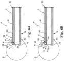
- FIGS. 6A and 6B are side cross-sectional views of the distal end 36 of the direct visualization catheter 22 of FIG. 2 , in accordance with some embodiments of this disclosure.
- FIG. 6A shows the catheter 22 with the articulating camera assembly 40 having a viewing direction V 1 .
- FIG. 6B shows the catheter 22 with the articulating camera assembly 40 having a viewing direction V 2 that is different from viewing direction V 1 .
- the articulating camera assembly 40 can include a camera 352 and an adjustment mechanism 354.
- the adjustment mechanism 354 can vary the viewing direction observed by the camera 352 relative to the distal end 36.
- FIG. 6A shows the catheter 22 with the articulating camera assembly 40 having a viewing direction V 1 .
- FIG. 6B shows the catheter 22 with the articulating camera assembly 40 having a viewing direction V 2 that is different from viewing direction V 1 .
- the articulating camera assembly 40 can include a camera 352 and an adjustment mechanism 354.
- the adjustment mechanism 354 can vary the viewing direction observed by the camera
- the adjustment mechanism 354 can include a hinge 356, a biasing element 358, and a control element 360.
- the plurality of lumens of the elongate shaft 28 can further include an inflation lumen 362 and a camera lumen 364.
- the inflation lumen 362 can extend to the handle 24 and on to a pressurized source of saline for inflation of the balloon 26 once the catheter 22 is positioned for viewing in the heart 12 of the patient 10 ( FIG. 1 ).
- the camera 352 can include any type of solid state image sensor known in the art, for example and without limitation, a complementary metal-oxide-semiconductor (CMOS) image sensor or a charge-coupled device (CCD) image sensor.
- CMOS complementary metal-oxide-semiconductor
- CCD charge-coupled device
- the image sensor can be encased within a protective box, or frame.
- the hinge 356 is configured to permit the camera 352 to move relative to the distal end 36 of the elongate shaft 28.
- the hinge 356 can be a multipart hinge including a hinge pin as is known in the art.
- the hinge 356 can be formed of a biocompatible metal, such as stainless steel, or a biocompatible polymer, such as PEEK.
- One part of the hinge 356 can be coupled to the camera 352, while another part is coupled to a radially outward facing surface of the slot 44 to couple the camera 352 to the elongate shaft 28, as shown in FIG. 6A .
- the hinge 356 permits movement of the camera 352 relative to the distal end 36 of the elongate shaft 28 about an axis defined by the hinge pin.
- the hinge 356 can include a hinge pin that extends through holes in the frame of the camera 352, the holes sized to permit free rotation of the frame relative to the pin.
- the pin can be formed of a biocompatible metal, such as stainless steel, or a biocompatible polymer, such as PEEK.
- the pin can be coupled on either end to opposite sidewalls of the slot 44 to connect the camera 352 to the elongate shaft 28 to permit movement of the camera 352 relative to the distal end 36 of the elongate shaft 28 about the hinge 356.
- the biasing element 358 can be formed of any type of biocompatible elastic material, for example, and without limitation, nitinol, spring steel alloys (medical grade), and polymers, such as polyethylene terephthalate (e.g. Mylar ® ), poly(p-xylylene), Kevlar ® , ultra-high-molecular-weight polyethylene, or nylon.
- the biasing element 358 can be configured as, for example, a helical coil spring, a leaf spring, or an elastic band.
- the biasing element 358 is configured with respect to the hinge 356 to provide a first force to maintain the hinge 356 in a fixed position in the absence of other forces.
- the hinge 356 and the biasing element 358 can be integrated.
- the hinge 356 can be in the form of a single L-shaped piece of biocompatible elastic material, such as those described above, thus integrating the hinge 356 and the biasing element 358.
- the first force of the elastic material can maintain the hinge 356/biasing element 358 in the L-shape in the absence of other forces.
- the control element 360 can be configured to selectively apply a second force to the hinge 356 or to the camera 352 opposite the first force to counter the first force of the biasing element 358 and cause movement of the camera 352 relative to the distal end 36 of the elongate shaft 28.
- the control element 360 includes an actuation thread coupled to the camera 352, as shown in FIG. 6A .
- the actuation thread is flexible and can be formed of, for example, a metal wire or a polymer thread made of, for example, Kevlar ® , graphene, or nylon.
- the control element 360 can extend from the camera 352, through the camera lumen 364, and at least to the proximal end 34 of the elongate shaft 28. In the embodiment of FIG.
- the control element 360 extends to the actuator 30 on the handle 24 ( FIG. 1 ).
- the actuator 30 can be a position switch that pulls on the control element 360 (actuation thread) to various extents depending on the position of the position switch.
- the control element 360 (actuation thread) physically connects the actuator 30 (position switch) to the camera 352.
- the electrical lines 38 can extend from the camera 352, through the camera lumen 364, to the image processing device 20, as described above, to electrically connect the camera 352 to the image processing device 20.
- the hinge 356 can be a conductive hinge that includes a plurality of electrical conductors configured to electrically connect the electrical lines 38 to the camera 352.
- FIG. 6A shows the catheter 22 with the first force from the biasing element 358 applied to the hinge 356 and without the second force from the control element 360 being applied to the camera 352 so that the camera 352 has a viewing direction V 1 as shown.
- the second force is applied to the camera 352 by moving the actuator 30 ( FIG.1 ) to pull the control element 360 (actuation thread). Pulling the control element 360 moves the camera 352 about the hinge 356 and against the biasing element 358 to change the viewing direction to the viewing direction V 2 , which is different from the viewing direction V 1 .
- the viewing angle or direction of the camera 352 may be varied by adjusting the actuator 30 (position switch) to pull the control element 360 to varying extents.
- the viewing direction V 2 can form an angle C with respect to the viewing direction V 1 that can be as small as 1°, 5°, 10°, 20°, 30°, or 40°, or as large as 50°, 60°, 70°, 80°, 85°, or 89°, or between any two of the preceding angles.
- the angle C can range from 1° to 89°, 5° to 85°, 10° to 80°, 20° to 70°, 30° to 60°, or 40° to 50°.
- the angle C is positive when the viewing direction V 2 is directed radially outward relative to the viewing direction V 1 , as shown in FIG. 6B , and the angle C is negative when the viewing direction V 2 is directed radially inward relative to the viewing direction V 1 , as shown in FIG. 9B described below.
- FIGS. 7A and 7B are side cross-sectional views of the distal end 36 of another embodiment of the direct visualization catheter 22 of FIG. 2 , in accordance with this disclosure.
- FIG. 7A shows the catheter 22 with the articulating camera assembly 40 having a viewing direction V 1 .
- FIG. 7B shows the catheter 22 with the articulating camera assembly 40 having a viewing direction V 2 that is different from viewing direction V 1 .
- the embodiment shown in FIGS. 7A and 7B is substantially identical to that described above in reference to FIGS. 6A and 6B , except that the adjustment mechanism 354 includes a control element 460 instead of control element 360.
- the control element 460 can include an inflatable device 462 and a pressurized control lumen 464.
- the inflatable device 462 is a balloon-like structure disposed between the cap 42 at the distal end 36 and the camera 352 such that inflation of the inflatable device 462 applies the second force to the camera 352 opposite the first force to counter the first force of the biasing element 358 and cause movement of the camera 352 relative to the distal end 36 of the elongate shaft 28.
- the pressurized control lumen 464 can be a tube in fluid communication with the inflatable device 462 that extends from the inflatable device 462, through the camera lumen 364, and at least to the proximal end 34 of the elongate shaft 28. In the embodiment of FIG.
- the pressurized control lumen 464 extends to the actuator 30 on the handle 24 ( FIG. 1 ).
- the actuator 30 can be a pressure regulating device that controls the pressure of a fluid in the pressurized control lumen 464 and the inflatable device 462 to various levels to increase or decrease the inflation of the inflatable device 462.
- the fluid in the inflatable device 462 and the pressurized control lumen 464 is saline or helium.
- FIG. 7A shows the catheter 22 with the first force from the biasing element 358 applied to the hinge 356 and without the second force from the control element 460 being applied to the camera 352 so that the camera 352 has a viewing direction V 1 as shown.
- the second force is applied to the camera 352 by adjusting the actuator 30 ( FIG.1 ) to increase the pressure in the pressurized control lumen 464 and inflate the inflatable device 462.
- Inflating the inflatable device 462 moves the camera 352 about the hinge 356 and against the biasing element 358 to change the viewing direction to the viewing direction V 2 , which is different from the viewing direction V 1 .
- the viewing angle or direction of the camera 352 may be varied by adjusting the actuator 30 (pressure regulating device) to inflate the inflatable device 462 to varying extents.
- the viewing direction V 2 can form an angle C with respect to the viewing direction V 1 that can be as small as 1°, 5°, 10°, 20°, 30°, or 40°, or as large as 50°, 60°, 70°, 80°, 85°, or 89°, or between any two of the preceding angles.
- the angle C can range from 1° to 89°, 5° to 85°, 10° to 80°, 20° to 70°, 30° to 60°, or 40° to 50°.
- FIGS. 8A and 8B are side cross-sectional views of the distal end 36 of another embodiment of the direct visualization catheter 22 of FIG. 2 , in accordance with this disclosure.
- FIG. 8A shows the catheter 22 with the articulating camera assembly 40 having a viewing direction V 1 .
- FIG. 8B shows the catheter 22 with the articulating camera assembly 40 having a viewing direction V 2 that is different from viewing direction V 1 .
- the embodiment shown in FIGS. 8A and 8B is substantially identical to that described above in reference to FIGS. 6A and 6B , except that the adjustment mechanism 354 includes a control element 560 instead of control element 360.
- the control element 560 can include an electroactive element 562 and control wires 564.
- the electroactive element 562 may be formed of, for example, polyvinylidene fluoride, a ceramic piezoelectric compound, an ionic electroactive polymer, a dielectric electroactive polymer, a liquid crystal polymer, or a ferroelectric polymer.
- the electroactive element 562 is disposed between the cap 42 at the distal end 36 and the camera 352 such that when a voltage is applied to the electroactive element 562, the electroactive element 562 changes shape. The change in shape applies the second force to the camera 352 opposite the first force to counter the first force of the biasing element 358 and cause movement of the camera 352 relative to the distal end 36 of the elongate shaft 28.
- the control wires 564 can extend from electroactive element 562, through the camera lumen 364, and at least to the proximal end 34 of the elongate shaft 28. In the embodiment of FIG. 8A , the control wires 564 are in electrical communication with the electroactive element 562 and extend to the actuator 30 on the handle 24 ( FIG. 1 ).
- the actuator 30 can be a voltage regulating device that controls the electric field applied to the control wires 564 and thus to the electroactive element 562 to change the shape of the electroactive element 562.
- FIG. 8A shows the catheter 22 with the first force from the biasing element 358 applied to the hinge 356 and without the second force from the control element 560 being applied to the camera 352 so that the camera 352 has a viewing direction V 1 as shown.
- the second force is applied to the camera 352 by adjusting the actuator 30 ( FIG.1 ) to increase the electric field applied to electroactive element 562.
- the increased electric field causes the electroactive element 562 to change shape, moving the camera 352 about the hinge 356 and against the biasing element 358 to change the viewing direction to the viewing direction V 2 , which is different from the viewing direction V 1 .
- the viewing angle or direction of the camera 352 may be varied by adjusting the actuator 30 (voltage regulating device) to change the shape of the electroactive element 562 to varying extents.
- the viewing direction V 2 can form an angle C with respect to the viewing direction V 1 that can be as small as 1°, 5°, 10°, 20°, 30°, or 40°, or as large as 50°, 60°, 70°, 80°, 85°, or 89°, or between any two of the preceding angles.
- the angle C can range from 1° to 89°, 5° to 85°, 10° to 80°, 20° to 70°, 30° to 60°, or 40° to 50°.
- FIGS. 9A and 9B are side cross-sectional views of the distal end 36 of another embodiment of the direct visualization catheter 22 of FIG. 2 , in accordance with this disclosure.
- FIG. 9A shows the catheter 22 with the articulating camera assembly 40 having a viewing direction V 1 .
- FIG. 9B shows the catheter 22 with the articulating camera assembly 40 having a viewing direction V 2 that is different from viewing direction V 1 .
- the embodiment shown in FIGS. 9A and 9B can be substantially identical to that described above in reference to FIGS. 6A and 6B , except that the control element 360 is replaced by an actuation rod 660 and the hinge 356 is free to slide along the radially outward facing surface of the slot 44.
- the hinge 356 includes a hinge pin
- the hinge pin may ride in recesses (not shown) on opposite facing sides of the slot 44.
- the actuation rod 660 is coupled to the hinge 356.
- the actuation rod 660 can extend from the hinge 356, through the camera lumen 364, and at least to the proximal end 34 of the elongate shaft 28.
- the actuation rod 660 extends to the actuator 30 on the handle 24 ( FIG. 1 ).
- the actuator 30 can be a position switch that pushes on or pulls on the actuation rod 660 to various extents depending on the position of the position switch.
- the actuation rod 660 physically connects the actuator 30 (position switch) to the hinge 356.
- the actuation rod 660 can be a flexible rod or tube.
- the actuation rod 660 and can be formed as a slotted tube or a multi-filar coiled spring.
- the actuation rod 660 can be made out of, for example, nickel-titanium alloys, MP35N ® , steel alloys (medical grade), or alloys of cobalt and chromium.
- the actuation rod 660 can be stiffer than the actuation thread of the control element 360.
- FIG. 9A shows the catheter 22 with the biasing element 358 applying a first force about the hinge 356 to bias the camera 352 against the radially outward facing surface of the slot 44 of cap 42 of the elongate shaft 28 so that the camera 352 has a viewing direction V 1 as shown.
- the actuation rod 660 is pushed by adjusting the actuator 30 ( FIG. 1 ) to extend at least a distal portion of the camera 352 beyond the distal end 36 of the elongate shaft 28, permitting the camera 352 to move in a first direction B 1 to change the viewing direction to the viewing direction V 2 .
- Adjusting the actuator 30 again to pull on the actuation rod 660 retracts the camera 352 toward the proximal end 34 ( FIG.
- the viewing angle or direction of the camera 352 may be varied by adjusting the actuator 30 (position switch) to push or pull the actuation rod 660 to varying extents.
- the viewing direction V 2 can form an angle C with respect to the viewing direction V 1 that can be as small as -1°, -5°, -10°, -20°, -30°, or -40°, or as large as -50°, -60°, -70°, -80°, - 85°, or -89°, or between any two of the preceding angles.
- the angle C can range from -1° to -89°, -5° to -85°, -10° to -80°, -20° to -70°, -30° to -60°, or -40° to -50°.
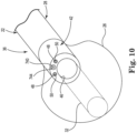
- FIG. 10 is a perspective schematic view of the distal end 36 of the direct visualization catheter 22, in accordance with embodiments of this disclosure.
- the embodiment of FIG. 10 is substantially identical to the embodiment of FIG. 2 , except that the articulating camera assembly 40 is replaced by an articulating camera assembly 740, and the slot 44 and the camera lumen 364 are replaced by a camera lumen 744.
- the articulating camera assembly 740 can be disposed within the camera lumen 744 to couple it to the distal end 36.
- FIGS. 11A and 11B are side cross-sectional views of the distal end 36 of the direct visualization catheter 22 of FIG. 10 , in accordance with embodiments of this disclosure.
- FIG. 11A shows the catheter 22 with the articulating camera assembly 740 having a viewing direction V 1 .
- FIG. 11B shows the catheter 22 with the articulating camera assembly 740 having a viewing direction V 2 that is different from viewing direction V 1 .
- the articulating camera assembly 740 can include a camera 352 and an adjustment mechanism 754.
- the adjustment mechanism 754 can vary the viewing direction observed by the camera 352 relative to the distal end 36.
- the adjustment mechanism 754 can include ball and socket joint 756, a helical spring 758, and a torque shaft 760.
- the ball and socket joint 756 can be primarily disposed within the camera lumen 744 with a portion of the ball and socket joint 756 projecting out of the camera lumen 744 at the distal end 36.
- the camera 352 can be connected to the portion of the ball and socket joint 756 projecting out of the camera lumen 744.
- the helical spring 758 can be connected to the ball and socket joint 756 within the camera lumen 744.
- the torque shaft 760 can be connected to an end of the helical spring 758 opposite the ball and socket joint 756.
- the torque shaft 760 can be a flexible rod or tube. In some embodiments, the torque shaft 760 and can be formed as a slotted tube or a multi-filar coiled spring.
- the torque shaft 760 can be made out of, for example, nickel-titanium alloys, MP35N ® , steel alloys (medical grade), or alloys of cobalt and chromium.
- the torque shaft 760 can extend from the helical spring 758, through the camera lumen 744, and at least to the proximal end 34 of the elongate shaft 28 ( FIG. 1 ). In the embodiment of FIG. 11A , the torque shaft 760 extends to the actuator 30 on the handle 24 ( FIG. 1 ).
- the actuator 30 can be a lever or joy stick that rotates the torque shaft 760 to various extents depending on the position of the lever or joy stick.
- FIG. 11A shows the catheter 22 with the ball and socket joint 756 positioned by the actuator 30 so that the camera 352 has a viewing direction V 1 as shown.
- the ball and socket joint 756 is positioned by the actuator 30 rotating the torque shaft 760, which rotates the helical spring 758 to move adjust the ball and socket joint 756 so that the camera 352 has a viewing direction V 2 , which is different from the viewing direction V 1 .
- the viewing angle or direction of the camera 352 may be varied by adjusting the actuator 30 (lever or joy stick) to rotate the torque shaft 760 to varying extents.
- the viewing direction V 2 can form an angle C with respect to the viewing direction V 1 that can be as small as -1°, -5°, -10°, -20°, -30°, or -40°, or as large as -50°, -60°, -70°, -80°, - 85°, or -89°, or between any two of the preceding angles.
- the angle C can range from -1° to -89°, -5° to -85°, -10° to -80°, -20° to -70°, -30° to -60°, or -40° to -50°.
- FIGS. 11A and 11B the viewing direction V 2 can form an angle C with respect to the viewing direction V 1 that can be as small as -1°, -5°, -10°, -20°, -30°, or -40°, or as large as -50°, -60°, -70°, -80°, - 85°, or -89°, or between any two of the preceding angles
- the viewing direction V 2 can form an angle C with respect to the viewing direction V 1 that can be as small as 1°, 5°, 10°, 20°, 30°, or 40°, or as large as 50°, 60°, 70°, 80°, 85°, or 89°, or between any two of the preceding angles.
- the angle C can range from 1° to 89°, 5° to 85°, 10° to 80°, 20° to 70°, 30° to 60°, or 40° to 50°.
- the viewing direction V 2 can form an angle C with respect to the viewing direction V 1 that can range from -89° to 89°, -85° to 85°, -80° to 80°, -70° to 70°, -60° to 60°, -50° to 50°, -40° to 40°, -30° to 30°, -20° to 20°, -10° to 10°, or -5° to 5°.
Landscapes
- Health & Medical Sciences (AREA)
- Life Sciences & Earth Sciences (AREA)
- Surgery (AREA)
- General Health & Medical Sciences (AREA)
- Public Health (AREA)
- Veterinary Medicine (AREA)
- Pathology (AREA)
- Nuclear Medicine, Radiotherapy & Molecular Imaging (AREA)
- Animal Behavior & Ethology (AREA)
- Engineering & Computer Science (AREA)
- Biomedical Technology (AREA)
- Heart & Thoracic Surgery (AREA)
- Medical Informatics (AREA)
- Molecular Biology (AREA)
- Biophysics (AREA)
- Physics & Mathematics (AREA)
- Radiology & Medical Imaging (AREA)
- Optics & Photonics (AREA)
- Endoscopes (AREA)
- Media Introduction/Drainage Providing Device (AREA)
- Surgical Instruments (AREA)
- Oral & Maxillofacial Surgery (AREA)
Description
- The present disclosure relates to medical devices for direct visualization within a body. More specifically, the disclosure relates to catheters and systems for direct visualization within a blood pool in a minimally-invasive manner.
- Direct visualization of tissues within a patient can provide important information and guidance in the diagnosis and treatment of illnesses. With respect to heart diseases, direct visualization can be helpful, for example, in the diagnosis and treatment heart valve diseases, among other diseases. In vivo images provided by direct visualization can allow for a thorough inspection of tissues with higher resolution than other techniques, such as ultrasound. Procedures, such as a septal cross, mitral valve repair, and stitching of a valve annulus can all benefit from the accuracy provided by direct visualization.
- Direct visualization within the heart is challenging because the general opacity of blood can obscure the tissues to be viewed. Some direct visualization catheters employ a transparent balloon at the end of the catheter to displace blood adjacent to the tissues to be viewed. The balloon can be filled with saline and provide an optical lensing effect, further clarifying the view of a camera within the balloon at the end of the catheter.
- Publication
US 2017/296795 A1 discloses a device with the features of the preamble of claim 1. - According to the invention, a direct visualization catheter as recited in the independent claim is provided. The dependent claims define preferred embodiments.
- An embodiment of the present invention is a direct visualization catheter including a handle, a balloon, an elongate shaft, and a camera assembly. The elongate shaft has a proximal end and a distal end opposite the proximal end. The proximal end is coupled to the handle. The distal end is coupled to the balloon and defines a longitudinal axis. The camera assembly is coupled to the distal end of the elongate shaft and is disposed within the balloon. The camera assembly includes a camera and an adjustment mechanism for varying a configuration of the camera relative to the distal end of the elongate shaft between a delivery configuration and a deployed configuration. The camera faces primarily in a radial direction in the delivery configuration and the camera faces primarily in an axial direction in the deployed configuration.
-
-
FIG. 1 is a schematic view illustrating in use of a system for direct visualization within a patient's heart, in accordance with embodiments of this disclosure. -
FIG. 2 is a perspective schematic view of a distal end of a direct visualization catheter, in accordance with embodiments of this disclosure. -
FIGS. 3A and 3B are side cross-sectional views of the distal end of the direct visualization catheter ofFIG. 2 , in accordance with some embodiments of this disclosure. -
FIGS. 4A and 4B are side cross-sectional views of the distal end of another embodiment of the direct visualization catheter ofFIG. 2 , in accordance with some embodiments of this disclosure. -
FIGS. 5A and 5B are side cross-sectional views of the distal end of another embodiment of the direct visualization catheter ofFIG. 2 , in accordance with some embodiments of this disclosure. -
FIGS. 6A and 6B are side cross-sectional views of the distal end of another embodiment of the direct visualization catheter ofFIG. 2 , in accordance with some embodiments of this disclosure. -
FIGS. 7A and 7B are side cross-sectional views of the distal end of another embodiment of the direct visualization catheter ofFIG. 2 , in accordance with some embodiments of this disclosure. -
FIGS. 8A and 8B are side cross-sectional views of the distal end of another embodiment of the direct visualization catheter ofFIG. 2 , in accordance with some embodiments of this disclosure. -
FIGS. 9A and 9B are side cross-sectional views of the distal end of another embodiment of the direct visualization catheter ofFIG. 2 , in accordance with some embodiments of this disclosure. -
FIG. 10 is a perspective schematic view of a distal end portion of another direct visualization catheter, in accordance with some embodiments of this disclosure. -
FIGS. 11A and 11B are side cross-sectional views of the distal end of another embodiment of the direct visualization catheter ofFIG. 10 , in accordance with some embodiments of this disclosure. - While this disclosure is amenable to various modifications and alternative forms, specific embodiments have been shown by way of example in the drawings and are described in detail below. The intention, however, is not to limit the disclosure to the particular embodiments described. On the contrary, this disclosure is intended to cover all modifications, equivalents, and alternatives falling within the scope of the disclosure as defined by the appended claims.
- Balloon catheters and systems and methods in accordance with embodiments of this disclosure can provide for direct visualization within a blood pool in a minimally-invasive manner. In some embodiments of this disclosure, an articulating camera disposed within a balloon at a distal end of a catheter can be configured for a low-profile delivery to the direct visualization site within the patient, and then the camera can be hinged away from the catheter in a deployed configuration. In the delivery configuration, the camera faces primarily in a radial direction. In the deployed configuration, the camera faces primarily in an axial direction for effective viewing.
- Such direct visualization catheters can have a smaller diameter during delivery. A smaller diameter catheter may cause less distress to the patient when, for example, passing the catheter through the septum, from the right side of the heart to the left side of the heart. It is believed that causing less distress from the passing of the catheter through the septum may result in better patient outcomes.
- An articulating camera disposed within a balloon at a distal end of a catheter can be aimed with an adjustment mechanism as described herein to vary a viewing direction observed by the camera relative to the catheter. By adjusting the viewing direction, navigation of the catheter can be enhanced and larger areas of tissue can be directly observed without having to move the catheter. It is believed that limiting the movement of the catheter may reduce any irritation caused by the catheter, resulting in better patient outcomes
-
FIG. 1 is a schematic view illustrating in use of a system for direct visualization within a patient's heart, in accordance with embodiments of this disclosure.FIG. 1 illustrates apatient 10 including aheart 12 and asystem 14 for direct visualization inserted into aright atrium 16 of theheart 12 for direct visualization of atricuspid valve 18. As shown inFIG. 1 , thesystem 14 can include animage processing device 20 and adirect visualization catheter 22. Theimage processing device 20 can include functionality for display of images, storage of images, and/or analysis of images. Thecatheter 22 can include ahandle 24, aballoon 26, and anelongate shaft 28. Thehandle 24 can include anactuator 30 and a plurality of lumens (not shown). Theballoon 26 can be formed of a transparent material and be a transparent balloon. In some embodiments, theballoon 26 can include aballoon lumen 32, as shown inFIG. 1 . Theelongate shaft 28 can be formed of a flexible, biocompatible polymer, such as, for example, silicone, polyisobutylene polyurethane, nylon, polyimide, polyetheretherketone, or a polyether block amide, such as Pebax® or Vestamid®. Theelongate shaft 28 can include aproximal end 34 and adistal end 36 opposite theproximal end 34. Theelongate shaft 28 can include a plurality of lumens (not shown) extending from theproximal end 34 to thedistal end 36. Theactuator 30 can be, for example, and without limitation, a position switch, a pressure regulating device, a voltage regulating device, or a lever or joy stick. - The
catheter 22 can be electrically connected to theimage processing device 20 byelectrical lines 38. Theproximal end 34 of theelongate shaft 28 can be coupled to thehandle 24 with at least one of the plurality of lumens in theelongate shaft 28 connected with at least one of the plurality of lumens in thehandle 24 to form a continuous lumen. Thedistal end 36 of theelongate shaft 28 is coupled to theballoon 26 with theballoon lumen 32 connected with at least one of the plurality of lumens in theelongate shaft 28. So arranged, it is possible to pass devices, for example, a SpyBite® Biopsy Forceps from Boston Scientific Corporation, Natick, Massachusetts, from thehandle 24, through theelongate shaft 28, and out through theballoon 26. - In use, the
actuator 30 on thehandle 24 can adjust a viewing direction of an articulatingcamera assembly 40, not shown inFIG. 1 , but describe in embodiments below. The articulatingcamera assembly 40 can be coupled to thedistal end 36 of theelongate shaft 28. The articulatingcamera assembly 40 can be disposed within theballoon 26. Theballoon 26 can be filled with a biocompatible, transparent fluid, such as saline solution, to displace blood adjacent to the tissues to be viewed. The transparent fluid can provide an optical lensing effect, further clarifying the view of the articulatingcamera assembly 40. Image output signals from the articulatingcamera assembly 40 can be sent to theimage processing device 20 over theelectrical lines 38. In some embodiments, theelectrical lines 38 can also supply power from theimage processing device 20 to the articulatingcamera assembly 40. In other embodiments, theelectrical lines 38 can also connect to a separate power source to supply power to the articulatingcamera assembly 40. -
FIG. 2 is a perspective schematic view of thedistal end 36 of thedirect visualization catheter 22, in accordance with some embodiments of this disclosure. Thedistal end 36 can define a longitudinal axis A. In some embodiments, theelongate shaft 28 can further include acap 42 at thedistal end 36, as shown inFIG. 2 . Thecap 42 can be formed of a variety of biocompatible materials that are typically harder than the flexible polymer of rest of theelongate shaft 28. Suitable materials for thecap 42 can include, for example, stainless steel, nickel-titanium alloys, MP35N®, Elgiloy®, and polymers such as polyetheretherketone, polyvinyl chloride, perfluoroalkoxy, polycarbonate, polyimide, polyethylene terephthalate, and polyetherimide. Thecap 42 can include aslot 44, and plurality of lumens, such asdelivery lumen 46, and at least one lighting lumen 48 (two shown) that align with corresponding lumens in the rest of theelongate shaft 28. Thedelivery lumen 46 is one of the plurality of lumens that extends from thedistal end 36, through theelongate shaft 28, and into thehandle 24. Thedelivery lumen 46 can be used to pass devices from thehandle 24, through theelongate shaft 28, and out through theballoon lumen 32. In embodiments without aballoon lumen 32, the devices passed through thecatheter 22 can penetrate theballoon 26. For clarity of illustration, theballoon lumen 32 is omitted fromFIGS. 3A, 3B ,4A, 4B ,5A, 5B ,6A, 6B ,7A, 7B ,8A, 8B ,9A, 9B , and11A, 11B . However, it is understood that all embodiments may include theballoon lumen 32. - The
lighting lumen 48 can include a lighting device 50 (two shown). Thelighting device 50 can include, for example and without limitation, a fiber optic cable or a light emitting diode. Thelighting device 50 provides illumination for the articulatingcamera assembly 40. Theballoon 26 can be attached around a circumference of theelongate shaft 28 by, for example, an adhesive. Theballoon 26 can be attached to either or both of thecap 42 or a portion of theelongate shaft 28 adjacent to thecap 42. In some embodiments, the articulatingcamera assembly 40 can be disposed within theslot 44 to couple it to thedistal end 36. -
FIGS. 3A and 3B are side cross-sectional views of thedistal end 36 of thedirect visualization catheter 22 ofFIG. 2 , in accordance with embodiments of this disclosure.FIG. 3A shows thecatheter 22 with the articulatingcamera assembly 40 in a delivery configuration.FIG. 3B shows thecatheter 22 with the articulatingcamera assembly 40 in a deployed configuration. As shown inFIG. 3A , the articulatingcamera assembly 40 includes acamera 52 and anadjustment mechanism 54. Theadjustment mechanism 54 can vary the direction faced by thecamera 52 relative to the longitudinal axis A. In the embodiment shown inFIG. 3A , theadjustment mechanism 54 includes ahinge 56, a biasingelement 58, and acontrol element 60. The plurality of lumens of theelongate shaft 28 can further include aninflation lumen 62 and acamera lumen 64. Theinflation lumen 62 can extend to thehandle 24 and on to a pressurized source of saline for inflation of theballoon 26 once thecatheter 22 is positioned for viewing theheart 12 in the patient 10 (FIG. 1 ). - The
camera 52 can include any type of solid state image sensor known in the art, for example and without limitation, a complementary metal-oxide-semiconductor (CMOS) image sensor or a charge-coupled device (CCD) image sensor. In some embodiments, the image sensor can be encased within a protective frame (not shown). Thecamera 52 can be relatively thin but with a relatively large image sensing area. That is, thecamera 52 can be shaped like a plate with the image sensing area on a large side of the plate. The relatively large image sensing area can provide good quality imaging. - The
hinge 56 is configured to permit thecamera 52 to move relative to thedistal end 36 of theelongate shaft 28. In some embodiments, thehinge 56 can be a multipart hinge including a hinge pin as is known in the art. The hinge can be formed of a biocompatible metal, such as stainless steel, or a biocompatible polymer, such as PEEK. One part of thehinge 56 can be coupled to the frame of thecamera 52, while another part is coupled to a radially outward facing surface of theslot 44 to couple thecamera 52 to theelongate shaft 28, as shown inFIG. 3A . Thehinge 56 permits movement of thecamera 52 relative to thedistal end 36 of theelongate shaft 28 about an axis defined by the hinge pin. - In some other embodiments, the
hinge 56 can include a hinge pin that extends through holes in the frame of thecamera 52, the holes sized to permit free rotation of the frame relative to the pin. The pin can be formed of a biocompatible metal, such as stainless steel, or a biocompatible polymer, such as PEEK. The pin can be coupled on either end to opposite sidewalls of theslot 44 to connect thecamera 52 to theelongate shaft 28 to permit movement of thecamera 52 relative to thedistal end 36 of theelongate shaft 28 about thehinge 56. - The biasing
element 58 can be formed of any type of biocompatible elastic material, for example, and without limitation, nitinol, spring steel alloys (medical grade), and polymers, such as polyethylene terephthalate (e.g. Mylar®), poly(p-xylylene), Kevlar®, ultra-high-molecular-weight polyethylene, or nylon. The biasingelement 58 can be configured as, for example, a helical coil spring, a leaf spring, or an elastic band. The biasingelement 58 is configured with respect to thehinge 56 to provide a first force to maintain thehinge 56 in a fixed position in the absence of other forces. - In some other embodiments, the
hinge 56 and the biasingelement 58 can be integrated. For example, in some embodiments thehinge 56 can be in the form of a single L-shaped piece of biocompatible elastic material, such as those described above, thus integrating thehinge 56 and the biasingelement 58. The first force of the elastic material can maintain thehinge 56/biasingelement 58 in the L-shape in the absence of other forces. - The
control element 60 is configured to selectively apply a second force to thehinge 56 or to thecamera 52 opposite the first force to counter the first force of the biasingelement 58 and cause movement of thecamera 52 relative to thedistal end 36 of theelongate shaft 28. In some embodiments, thecontrol element 60 includes an actuation thread coupled to thecamera 52, as shown inFIG. 3A . The actuation thread is flexible and can be formed of, for example, a metal wire or a polymer thread made of, for example, Kevlar®, graphene, or nylon. Thecontrol element 60 can extend from thecamera 52, through thecamera lumen 64, and at least to theproximal end 34 of theelongate shaft 28. In the embodiment ofFIG. 3A , thecontrol element 60 extends to theactuator 30 on the handle 24 (FIG. 1 ). Theactuator 30 can be a position switch that pulls on the control element 60 (actuation thread) to various extents depending on the position of the position switch. Thus, in the embodiment ofFIG. 3A , the control element 60 (actuation thread) physically connects the actuator 30 (position switch) to thecamera 52. - In some embodiments, the
electrical lines 38 can extend from thecamera 52, through thecamera lumen 64, to theimage processing device 20, as described above, to electrically connect thecamera 52 to theimage processing device 20. In some embodiments, thehinge 56 can be a conductive hinge that includes a plurality of electrical conductors configured to electrically connect theelectrical lines 38 to thecamera 52. -
FIG. 3A shows thecatheter 22 with the first force from the biasingelement 58 applied to thehinge 56 and without the second force from thecontrol element 60 being applied to thecamera 52 so that thecamera 52 faces in a primarily radial direction. For the purposes of this disclosure, thecamera 52 faces in a primarily radial direction when it faces more in a radial direction relative to the longitudinal axis than in an axial direction relative to the longitudinal axis A. In the embodiment shown inFIG. 3A , thecamera 52 faces in a viewing direction V1. The viewing direction V1 is a completely radial inward direction toward the longitudinal axis A and does not face at all in the axial direction. So configured, thecamera 52 has a low profile and does not extend beyond a diameter D1 of theelongate shaft 28. - As shown in
FIG. 3A , in the delivery configuration, thecamera 52 presents a small profile in the axial direction. This permits the diameter D1 of theelongate shaft 28 to be relatively small for ease of delivery and still accommodate thecamera 52, while a diameter D2 of thedelivery lumen 46 can be relatively large. For example, in some prior art direct visualization catheters in which a camera faces primarily axially during delivery, a 4 mm diameter (12 French) catheter is necessary to provide enough axially-facing space to accommodate the axially-facing camera and a 2.2 mm - 2.5 mm diameter (7 French) delivery lumen. In contrast, in some embodiments of this disclosure, the diameter D1 of theelongate shaft 28 can be from 3.1 mm to 3.5 mm (10 French) while maintaining the lumen diameter D2 of thedelivery lumen 46 at 2.2 mm to 2.5 mm. - Once the
distal end 36 is delivered to the viewing site within theheart 12 of the patient 10 (FIG. 1 ), the articulatedcamera assembly 40 can be deployed, as shown inFIG. 3B . InFIG. 3B , the second force is applied to thecamera 52 by moving the actuator 30 (FIG.1 ) to pull the control element 60 (actuation thread). Pulling thecontrol element 60 moves thecamera 52 about thehinge 56 and against the biasingelement 58 so that thecamera 52 faces in a primarily axial direction. For the purposes of this disclosure, thecamera 52 faces in a primarily axial direction when it faces more in the axial direction relative to the longitudinal axis than in the radial direction relative to the longitudinal axis A. In the embodiment shown inFIG. 3B , thecamera 52 faces in a viewing direction V2. The viewing direction V2 is a completely axial direction toward and does not face at all in the radial direction. In the deployed configuration, the relatively large image sensing area of thecamera 52 faces axially to provide high quality direct visualization of tissue. - As shown in
FIG. 3B , in the deployed configuration thecamera 52 extends radially beyond theelongate shaft 28. Once direct visualization of the tissue is completed, the actuator 30 (FIG. 1 ) can be moved to release thecontrol element 60, permitting the biasingelement 58 to move thecamera 52 about thehinge 56 so that thecamera 52 once again faces in the primarily radial direction and does not extend radially beyond theelongate shaft 28. In this way, thecatheter 22 returns to a low-profile which may case less distress to the patient 10 when being removed from thepatient 10. -
FIGS. 4A and 4B are side cross-sectional views of thedistal end 36 of another embodiment of thedirect visualization catheter 22 ofFIG. 2 , in accordance with this disclosure.FIG. 4A shows thecatheter 22 with the articulatingcamera assembly 40 in a delivery configuration.FIG. 4B shows thecatheter 22 with the articulatingcamera assembly 40 in a deployed configuration. The embodiment shown inFIGS. 4A and 4B is substantially identical to that described above in reference toFIGS. 3A and 3B , except that theadjustment mechanism 54 includes acontrol element 160 instead ofcontrol element 60. - The
control element 160 can include aninflatable device 162 and apressurized control lumen 164. Theinflatable device 162 is a balloon-like structure disposed between thecap 42 at thedistal end 36 and thecamera 52 such that inflation of theinflatable device 162 applies the second force to thecamera 52 opposite the first force to counter the first force of the biasingelement 58 and cause movement of thecamera 52 relative to thedistal end 36 of theelongate shaft 28. In some embodiments, thepressurized control lumen 164 can be a tube in fluid communication with theinflatable device 162 that extends from theinflatable device 162, through thecamera lumen 64, and at least to theproximal end 34 of theelongate shaft 28. In the embodiment ofFIG. 4A , thepressurized control lumen 164 extends to theactuator 30 on the handle 24 (FIG. 1 ). Theactuator 30 can be a pressure regulating device that controls the pressure of a fluid in thepressurized control lumen 164 and theinflatable device 162 to various levels to increase or decrease the inflation of theinflatable device 162. In some embodiments, the fluid in theinflatable device 162 and thepressurized control lumen 164 is saline or helium. -
FIG. 4A shows thecatheter 22 with the first force from the biasingelement 58 applied to thehinge 56 and without the second force from thecontrol element 160 being applied to thecamera 52 so that thecamera 52 faces in a primarily radial direction. In the embodiment shown inFIG. 4A , thecamera 52 faces in a viewing direction V3. The viewing direction V3 is a mostly radially outward direction away from the longitudinal axis A and faces the axial direction to a lesser extent than the radial direction. So configured, thecamera 52 has a low profile and does not extend beyond a diameter D1 of theelongate shaft 28. - As shown in
FIG. 4A , in the delivery configuration, thecamera 52 presents a small profile in the axial direction. This permits the diameter D1 of theelongate shaft 28 to be relatively small for ease of delivery and still accommodate thecamera 52, while a diameter D2 of thedelivery lumen 46 can be relatively large, as described above in reference to the embodiment shown inFIG. 3A . - Once the
distal end 36 is delivered to the viewing site within theheart 12 of the patient 10 (FIG. 1 ), the articulatedcamera assembly 40 can be deployed, as shown inFIG. 4B . InFIG. 4B , the second force is applied to thecamera 52 by adjusting the actuator 30 (FIG.1 ) to increase the pressure in thepressurized control lumen 164 and inflate theinflatable device 162. Inflating theinflatable device 162 moves thecamera 52 about thehinge 56 and against the biasingelement 58 so that thecamera 52 faces a viewing direction V4. The viewing direction V4 is in a primarily axial direction. In the deployed configuration, the relatively large image sensing area of thecamera 52 faces axially to provide high quality direct visualization of tissue. - As shown in
FIG. 4B , in the deployed configuration thecamera 52 extends radially beyond theelongate shaft 28. Once direct visualization of the tissue is completed, the actuator 30 (FIG. 1 ) can be adjusted to reduce the pressure in thepressurized control lumen 164 and deflate theinflatable device 162. As theinflatable device 162 deflates, the biasingelement 58 to moves thecamera 52 about thehinge 56 so that thecamera 52 once again faces in the primarily radial direction and does not extend radially beyond theelongate shaft 28. In this way, thecatheter 22 returns to a low-profile which may case less distress to the patient 10 when being removed from the patient 10 (FIG. 1 ). -
FIGS. 5A and 5B are side cross-sectional views of thedistal end 36 of another embodiment of thedirect visualization catheter 22 ofFIG. 2 , in accordance with this disclosure.FIG. 5A shows thecatheter 22 with the articulatingcamera assembly 40 in a delivery configuration.FIG. 5B shows thecatheter 22 with the articulatingcamera assembly 40 in a deployed configuration. The embodiment shown inFIGS. 5A and 5B is substantially identical to that described above in reference toFIGS. 3A and 3B , except that theadjustment mechanism 54 includes acontrol element 260 instead ofcontrol element 60. - The
control element 260 can include anelectroactive element 262 andcontrol wires 264. Theelectroactive element 262 may be formed of, for example, polyvinylidene fluoride, a ceramic piezoelectric compound, an ionic electroactive polymer, a dielectric electroactive polymer, a liquid crystal polymer, or a ferroelectric polymer. Theelectroactive element 262 is disposed between thecap 42 at thedistal end 36 and thecamera 52 such that when a voltage is applied to theelectroactive element 262, theelectroactive element 262 changes shape. The change in shape applies the second force to thecamera 52 opposite the first force to counter the first force of the biasingelement 58 and cause movement of thecamera 52 relative to thedistal end 36 of theelongate shaft 28. Thecontrol wires 264 can extend fromelectroactive element 262, through thecamera lumen 64, and at least to theproximal end 34 of theelongate shaft 28. In the embodiment ofFIG. 5A , thecontrol wires 264 are in electrical communication with theelectroactive element 262 and extend to theactuator 30 on the handle 24 (FIG. 1 ). Theactuator 30 can be a voltage regulating device that controls the electric field applied to thecontrol wires 264 and thus to theelectroactive element 262 to change the shape of theelectroactive element 262. -
FIG. 5A shows thecatheter 22 with the first force from the biasingelement 58 applied to thehinge 56 and without the second force from thecontrol element 260 being applied to thecamera 52 so that thecamera 52 faces in a primarily radial direction. In the embodiment shown inFIG. 5A , thecamera 52 faces in a viewing direction V5. The viewing direction V5 is a mostly radially outward direction away from the longitudinal axis A and faces the axial direction to a lesser extent than the radial direction. So configured, thecamera 52 has a low profile and does not extend beyond a diameter D1 of theelongate shaft 28. - As shown in
FIG. 5A , in the delivery configuration, thecamera 52 presents a small profile in the axial direction. This permits the diameter D1 of theelongate shaft 28 to be relatively small for ease of delivery and still accommodate thecamera 52, while a diameter D2 of thedelivery lumen 46 can be relatively large, as described above in reference to the embodiment shown inFIG. 3A . - Once the
distal end 36 is delivered to the viewing site within theheart 12 of the patient 10 (FIG. 1 ), the articulatedcamera assembly 40 can be deployed, as shown inFIG. 5B . InFIG. 5B , the second force is applied to thecamera 52 by adjusting the actuator 30 (FIG.1 ) to increase the electric field applied toelectroactive element 262. The increased electric field causes theelectroactive element 262 to change shape, moving thecamera 52 about thehinge 56 and against the biasingelement 58 so that thecamera 52 faces a viewing direction V6. The viewing direction V6 is in a primarily axial direction. In the deployed configuration, the relatively large image sensing area of thecamera 52 faces axially to provide high quality direct visualization of tissue. - As shown in
FIG. 5B , in the deployed configuration thecamera 52 extends radially beyond theelongate shaft 28. Once direct visualization of the tissue is completed, the actuator 30 (FIG. 1 ) can be adjusted to decrease the electric field applied toelectroactive element 262. The decreased electric field causes theelectroactive element 262 to change shape, permitting the biasingelement 58 to move thecamera 52 about thehinge 56 so that thecamera 52 once again faces in the primarily radial direction and does not extend radially beyond theelongate shaft 28. In this way, thecatheter 22 returns to a low-profile which may case less distress to the patient 10 when being removed from thepatient 10. -
FIGS. 6A and 6B are side cross-sectional views of thedistal end 36 of thedirect visualization catheter 22 ofFIG. 2 , in accordance with some embodiments of this disclosure.FIG. 6A shows thecatheter 22 with the articulatingcamera assembly 40 having a viewing direction V1.FIG. 6B shows thecatheter 22 with the articulatingcamera assembly 40 having a viewing direction V2 that is different from viewing direction V1. As shown inFIG. 6A , the articulatingcamera assembly 40 can include acamera 352 and anadjustment mechanism 354. Theadjustment mechanism 354 can vary the viewing direction observed by thecamera 352 relative to thedistal end 36. In the embodiment shown inFIG. 6A , theadjustment mechanism 354 can include ahinge 356, a biasingelement 358, and acontrol element 360. The plurality of lumens of theelongate shaft 28 can further include aninflation lumen 362 and acamera lumen 364. Theinflation lumen 362 can extend to thehandle 24 and on to a pressurized source of saline for inflation of theballoon 26 once thecatheter 22 is positioned for viewing in theheart 12 of the patient 10 (FIG. 1 ). - The
camera 352 can include any type of solid state image sensor known in the art, for example and without limitation, a complementary metal-oxide-semiconductor (CMOS) image sensor or a charge-coupled device (CCD) image sensor. In some embodiments, the image sensor can be encased within a protective box, or frame. - The
hinge 356 is configured to permit thecamera 352 to move relative to thedistal end 36 of theelongate shaft 28. In some embodiments, thehinge 356 can be a multipart hinge including a hinge pin as is known in the art. Thehinge 356 can be formed of a biocompatible metal, such as stainless steel, or a biocompatible polymer, such as PEEK. One part of thehinge 356 can be coupled to thecamera 352, while another part is coupled to a radially outward facing surface of theslot 44 to couple thecamera 352 to theelongate shaft 28, as shown inFIG. 6A . Thehinge 356 permits movement of thecamera 352 relative to thedistal end 36 of theelongate shaft 28 about an axis defined by the hinge pin. - In some other embodiments, the
hinge 356 can include a hinge pin that extends through holes in the frame of thecamera 352, the holes sized to permit free rotation of the frame relative to the pin. The pin can be formed of a biocompatible metal, such as stainless steel, or a biocompatible polymer, such as PEEK. The pin can be coupled on either end to opposite sidewalls of theslot 44 to connect thecamera 352 to theelongate shaft 28 to permit movement of thecamera 352 relative to thedistal end 36 of theelongate shaft 28 about thehinge 356. - The biasing
element 358 can be formed of any type of biocompatible elastic material, for example, and without limitation, nitinol, spring steel alloys (medical grade), and polymers, such as polyethylene terephthalate (e.g. Mylar®), poly(p-xylylene), Kevlar®, ultra-high-molecular-weight polyethylene, or nylon. The biasingelement 358 can be configured as, for example, a helical coil spring, a leaf spring, or an elastic band. The biasingelement 358 is configured with respect to thehinge 356 to provide a first force to maintain thehinge 356 in a fixed position in the absence of other forces. - In some other embodiments, the
hinge 356 and the biasingelement 358 can be integrated. For example, in some embodiments thehinge 356 can be in the form of a single L-shaped piece of biocompatible elastic material, such as those described above, thus integrating thehinge 356 and the biasingelement 358. The first force of the elastic material can maintain thehinge 356/biasing element 358 in the L-shape in the absence of other forces. - The
control element 360 can be configured to selectively apply a second force to thehinge 356 or to thecamera 352 opposite the first force to counter the first force of the biasingelement 358 and cause movement of thecamera 352 relative to thedistal end 36 of theelongate shaft 28. In some embodiments, thecontrol element 360 includes an actuation thread coupled to thecamera 352, as shown inFIG. 6A . The actuation thread is flexible and can be formed of, for example, a metal wire or a polymer thread made of, for example, Kevlar®, graphene, or nylon. Thecontrol element 360 can extend from thecamera 352, through thecamera lumen 364, and at least to theproximal end 34 of theelongate shaft 28. In the embodiment ofFIG. 6A , thecontrol element 360 extends to theactuator 30 on the handle 24 (FIG. 1 ). Theactuator 30 can be a position switch that pulls on the control element 360 (actuation thread) to various extents depending on the position of the position switch. Thus, in the embodiment ofFIG. 6A , the control element 360 (actuation thread) physically connects the actuator 30 (position switch) to thecamera 352. - In some embodiments, the
electrical lines 38 can extend from thecamera 352, through thecamera lumen 364, to theimage processing device 20, as described above, to electrically connect thecamera 352 to theimage processing device 20. In some embodiments, thehinge 356 can be a conductive hinge that includes a plurality of electrical conductors configured to electrically connect theelectrical lines 38 to thecamera 352. -
FIG. 6A shows thecatheter 22 with the first force from the biasingelement 358 applied to thehinge 356 and without the second force from thecontrol element 360 being applied to thecamera 352 so that thecamera 352 has a viewing direction V1 as shown. InFIG. 6B , the second force is applied to thecamera 352 by moving the actuator 30 (FIG.1 ) to pull the control element 360 (actuation thread). Pulling thecontrol element 360 moves thecamera 352 about thehinge 356 and against the biasingelement 358 to change the viewing direction to the viewing direction V2, which is different from the viewing direction V1. In this way, the viewing angle or direction of thecamera 352 may be varied by adjusting the actuator 30 (position switch) to pull thecontrol element 360 to varying extents. - In some embodiments according to
FIGS. 6A and 6B , the viewing direction V2 can form an angle C with respect to the viewing direction V1 that can be as small as 1°, 5°, 10°, 20°, 30°, or 40°, or as large as 50°, 60°, 70°, 80°, 85°, or 89°, or between any two of the preceding angles. For example, in some embodiments, the angle C can range from 1° to 89°, 5° to 85°, 10° to 80°, 20° to 70°, 30° to 60°, or 40° to 50°. For the purposes of this disclosure, the angle C is positive when the viewing direction V2 is directed radially outward relative to the viewing direction V1, as shown inFIG. 6B , and the angle C is negative when the viewing direction V2 is directed radially inward relative to the viewing direction V1, as shown inFIG. 9B described below. -
FIGS. 7A and 7B are side cross-sectional views of thedistal end 36 of another embodiment of thedirect visualization catheter 22 ofFIG. 2 , in accordance with this disclosure.FIG. 7A shows thecatheter 22 with the articulatingcamera assembly 40 having a viewing direction V1.FIG. 7B shows thecatheter 22 with the articulatingcamera assembly 40 having a viewing direction V2 that is different from viewing direction V1. The embodiment shown inFIGS. 7A and 7B is substantially identical to that described above in reference toFIGS. 6A and 6B , except that theadjustment mechanism 354 includes acontrol element 460 instead ofcontrol element 360. - The
control element 460 can include aninflatable device 462 and apressurized control lumen 464. Theinflatable device 462 is a balloon-like structure disposed between thecap 42 at thedistal end 36 and thecamera 352 such that inflation of theinflatable device 462 applies the second force to thecamera 352 opposite the first force to counter the first force of the biasingelement 358 and cause movement of thecamera 352 relative to thedistal end 36 of theelongate shaft 28. In some embodiments, thepressurized control lumen 464 can be a tube in fluid communication with theinflatable device 462 that extends from theinflatable device 462, through thecamera lumen 364, and at least to theproximal end 34 of theelongate shaft 28. In the embodiment ofFIG. 7A , thepressurized control lumen 464 extends to theactuator 30 on the handle 24 (FIG. 1 ). Theactuator 30 can be a pressure regulating device that controls the pressure of a fluid in thepressurized control lumen 464 and theinflatable device 462 to various levels to increase or decrease the inflation of theinflatable device 462. In some embodiments, the fluid in theinflatable device 462 and thepressurized control lumen 464 is saline or helium. -
FIG. 7A shows thecatheter 22 with the first force from the biasingelement 358 applied to thehinge 356 and without the second force from thecontrol element 460 being applied to thecamera 352 so that thecamera 352 has a viewing direction V1 as shown. InFIG. 7B , the second force is applied to thecamera 352 by adjusting the actuator 30 (FIG.1 ) to increase the pressure in thepressurized control lumen 464 and inflate theinflatable device 462. Inflating theinflatable device 462 moves thecamera 352 about thehinge 356 and against the biasingelement 358 to change the viewing direction to the viewing direction V2, which is different from the viewing direction V1. In this way, the viewing angle or direction of thecamera 352 may be varied by adjusting the actuator 30 (pressure regulating device) to inflate theinflatable device 462 to varying extents. - In some embodiments according to
FIGS. 7A and 7B , the viewing direction V2 can form an angle C with respect to the viewing direction V1 that can be as small as 1°, 5°, 10°, 20°, 30°, or 40°, or as large as 50°, 60°, 70°, 80°, 85°, or 89°, or between any two of the preceding angles. For example, in some embodiments, the angle C can range from 1° to 89°, 5° to 85°, 10° to 80°, 20° to 70°, 30° to 60°, or 40° to 50°. -
FIGS. 8A and 8B are side cross-sectional views of thedistal end 36 of another embodiment of thedirect visualization catheter 22 ofFIG. 2 , in accordance with this disclosure.FIG. 8A shows thecatheter 22 with the articulatingcamera assembly 40 having a viewing direction V1.FIG. 8B shows thecatheter 22 with the articulatingcamera assembly 40 having a viewing direction V2 that is different from viewing direction V1. The embodiment shown inFIGS. 8A and 8B is substantially identical to that described above in reference toFIGS. 6A and 6B , except that theadjustment mechanism 354 includes acontrol element 560 instead ofcontrol element 360. - The
control element 560 can include anelectroactive element 562 andcontrol wires 564. Theelectroactive element 562 may be formed of, for example, polyvinylidene fluoride, a ceramic piezoelectric compound, an ionic electroactive polymer, a dielectric electroactive polymer, a liquid crystal polymer, or a ferroelectric polymer. Theelectroactive element 562 is disposed between thecap 42 at thedistal end 36 and thecamera 352 such that when a voltage is applied to theelectroactive element 562, theelectroactive element 562 changes shape. The change in shape applies the second force to thecamera 352 opposite the first force to counter the first force of the biasingelement 358 and cause movement of thecamera 352 relative to thedistal end 36 of theelongate shaft 28. Thecontrol wires 564 can extend fromelectroactive element 562, through thecamera lumen 364, and at least to theproximal end 34 of theelongate shaft 28. In the embodiment ofFIG. 8A , thecontrol wires 564 are in electrical communication with theelectroactive element 562 and extend to theactuator 30 on the handle 24 (FIG. 1 ). Theactuator 30 can be a voltage regulating device that controls the electric field applied to thecontrol wires 564 and thus to theelectroactive element 562 to change the shape of theelectroactive element 562. -
FIG. 8A shows thecatheter 22 with the first force from the biasingelement 358 applied to thehinge 356 and without the second force from thecontrol element 560 being applied to thecamera 352 so that thecamera 352 has a viewing direction V1 as shown. InFIG. 8B , the second force is applied to thecamera 352 by adjusting the actuator 30 (FIG.1 ) to increase the electric field applied toelectroactive element 562. The increased electric field causes theelectroactive element 562 to change shape, moving thecamera 352 about thehinge 356 and against the biasingelement 358 to change the viewing direction to the viewing direction V2, which is different from the viewing direction V1. In this way, the viewing angle or direction of thecamera 352 may be varied by adjusting the actuator 30 (voltage regulating device) to change the shape of theelectroactive element 562 to varying extents. - In some embodiments according to
FIGS. 8A and 8B , the viewing direction V2 can form an angle C with respect to the viewing direction V1 that can be as small as 1°, 5°, 10°, 20°, 30°, or 40°, or as large as 50°, 60°, 70°, 80°, 85°, or 89°, or between any two of the preceding angles. For example, in some embodiments, the angle C can range from 1° to 89°, 5° to 85°, 10° to 80°, 20° to 70°, 30° to 60°, or 40° to 50°. -
FIGS. 9A and 9B are side cross-sectional views of thedistal end 36 of another embodiment of thedirect visualization catheter 22 ofFIG. 2 , in accordance with this disclosure.FIG. 9A shows thecatheter 22 with the articulatingcamera assembly 40 having a viewing direction V1.FIG. 9B shows thecatheter 22 with the articulatingcamera assembly 40 having a viewing direction V2 that is different from viewing direction V1. The embodiment shown inFIGS. 9A and 9B can be substantially identical to that described above in reference toFIGS. 6A and 6B , except that thecontrol element 360 is replaced by anactuation rod 660 and thehinge 356 is free to slide along the radially outward facing surface of theslot 44. In some embodiments, in which thehinge 356 includes a hinge pin, the hinge pin may ride in recesses (not shown) on opposite facing sides of theslot 44. - In contrast to control
element 360 in which the actuation thread is coupled to thecamera 352, theactuation rod 660 is coupled to thehinge 356. Theactuation rod 660 can extend from thehinge 356, through thecamera lumen 364, and at least to theproximal end 34 of theelongate shaft 28. In the embodiment ofFIG. 9A , theactuation rod 660 extends to theactuator 30 on the handle 24 (FIG. 1 ). Theactuator 30 can be a position switch that pushes on or pulls on theactuation rod 660 to various extents depending on the position of the position switch. Thus, in the embodiment ofFIG. 9A , theactuation rod 660 physically connects the actuator 30 (position switch) to thehinge 356. Theactuation rod 660 can be a flexible rod or tube. In some embodiments, theactuation rod 660 and can be formed as a slotted tube or a multi-filar coiled spring. In some embodiments, theactuation rod 660 can be made out of, for example, nickel-titanium alloys, MP35N®, steel alloys (medical grade), or alloys of cobalt and chromium. Theactuation rod 660 can be stiffer than the actuation thread of thecontrol element 360. -
FIG. 9A shows thecatheter 22 with the biasingelement 358 applying a first force about thehinge 356 to bias thecamera 352 against the radially outward facing surface of theslot 44 ofcap 42 of theelongate shaft 28 so that thecamera 352 has a viewing direction V1 as shown. InFIG. 9B , theactuation rod 660 is pushed by adjusting the actuator 30 (FIG. 1 ) to extend at least a distal portion of thecamera 352 beyond thedistal end 36 of theelongate shaft 28, permitting thecamera 352 to move in a first direction B1 to change the viewing direction to the viewing direction V2. Adjusting theactuator 30 again to pull on theactuation rod 660 retracts thecamera 352 toward the proximal end 34 (FIG. 1 ) of theelongate shaft 28. Pulling thecamera 352 back against thecap 42 applies a second force about thehinge 356 to counter the first force, moving thecamera 352 in a second direction B2 and back to the viewing direction V1 as shown inFIG. 9A . In this way, the viewing angle or direction of thecamera 352 may be varied by adjusting the actuator 30 (position switch) to push or pull theactuation rod 660 to varying extents. - In some embodiments according to
FIGS. 9A and 9B , the viewing direction V2 can form an angle C with respect to the viewing direction V1 that can be as small as -1°, -5°, -10°, -20°, -30°, or -40°, or as large as -50°, -60°, -70°, -80°, - 85°, or -89°, or between any two of the preceding angles. For example, in some embodiments, the angle C can range from -1° to -89°, -5° to -85°, -10° to -80°, -20° to -70°, -30° to -60°, or -40° to -50°. -
FIG. 10 is a perspective schematic view of thedistal end 36 of thedirect visualization catheter 22, in accordance with embodiments of this disclosure. The embodiment ofFIG. 10 is substantially identical to the embodiment ofFIG. 2 , except that the articulatingcamera assembly 40 is replaced by an articulatingcamera assembly 740, and theslot 44 and thecamera lumen 364 are replaced by acamera lumen 744. The articulatingcamera assembly 740 can be disposed within thecamera lumen 744 to couple it to thedistal end 36. -
FIGS. 11A and 11B are side cross-sectional views of thedistal end 36 of thedirect visualization catheter 22 ofFIG. 10 , in accordance with embodiments of this disclosure.FIG. 11A shows thecatheter 22 with the articulatingcamera assembly 740 having a viewing direction V1.FIG. 11B shows thecatheter 22 with the articulatingcamera assembly 740 having a viewing direction V2 that is different from viewing direction V1. As shown inFIG. 11A , the articulatingcamera assembly 740 can include acamera 352 and anadjustment mechanism 754. Theadjustment mechanism 754 can vary the viewing direction observed by thecamera 352 relative to thedistal end 36. In the embodiment shown inFIG. 11A , theadjustment mechanism 754 can include ball andsocket joint 756, ahelical spring 758, and atorque shaft 760. - The ball and socket joint 756 can be primarily disposed within the
camera lumen 744 with a portion of the ball and socket joint 756 projecting out of thecamera lumen 744 at thedistal end 36. Thecamera 352 can be connected to the portion of the ball and socket joint 756 projecting out of thecamera lumen 744. Thehelical spring 758 can be connected to the ball andsocket joint 756 within thecamera lumen 744. Thetorque shaft 760 can be connected to an end of thehelical spring 758 opposite the ball andsocket joint 756. Thetorque shaft 760 can be a flexible rod or tube. In some embodiments, thetorque shaft 760 and can be formed as a slotted tube or a multi-filar coiled spring. In some embodiments, thetorque shaft 760 can be made out of, for example, nickel-titanium alloys, MP35N®, steel alloys (medical grade), or alloys of cobalt and chromium. Thetorque shaft 760 can extend from thehelical spring 758, through thecamera lumen 744, and at least to theproximal end 34 of the elongate shaft 28 (FIG. 1 ). In the embodiment ofFIG. 11A , thetorque shaft 760 extends to theactuator 30 on the handle 24 (FIG. 1 ). Theactuator 30 can be a lever or joy stick that rotates thetorque shaft 760 to various extents depending on the position of the lever or joy stick. -
FIG. 11A shows thecatheter 22 with the ball and socket joint 756 positioned by theactuator 30 so that thecamera 352 has a viewing direction V1 as shown. InFIG. 11B , the ball andsocket joint 756 is positioned by theactuator 30 rotating thetorque shaft 760, which rotates thehelical spring 758 to move adjust the ball and socket joint 756 so that thecamera 352 has a viewing direction V2, which is different from the viewing direction V1. In this way, the viewing angle or direction of thecamera 352 may be varied by adjusting the actuator 30 (lever or joy stick) to rotate thetorque shaft 760 to varying extents. - In some embodiments according to
FIGS. 11A and 11B , the viewing direction V2 can form an angle C with respect to the viewing direction V1 that can be as small as -1°, -5°, -10°, -20°, -30°, or -40°, or as large as -50°, -60°, -70°, -80°, - 85°, or -89°, or between any two of the preceding angles. For example, in some embodiments, the angle C can range from -1° to -89°, -5° to -85°, -10° to -80°, -20° to -70°, -30° to -60°, or -40° to -50°. In other embodiments according toFIGS. 11A and 11B , the viewing direction V2 can form an angle C with respect to the viewing direction V1 that can be as small as 1°, 5°, 10°, 20°, 30°, or 40°, or as large as 50°, 60°, 70°, 80°, 85°, or 89°, or between any two of the preceding angles. For example, in some embodiments, the angle C can range from 1° to 89°, 5° to 85°, 10° to 80°, 20° to 70°, 30° to 60°, or 40° to 50°. In some further embodiments according toFIGS. 11A and 11B , the viewing direction V2 can form an angle C with respect to the viewing direction V1 that can range from -89° to 89°, -85° to 85°, -80° to 80°, -70° to 70°, -60° to 60°, -50° to 50°, -40° to 40°, -30° to 30°, -20° to 20°, -10° to 10°, or -5° to 5°.
Claims (8)
- A direct visualization catheter comprising:a handle;a balloon;an elongate shaft having a proximal end and a distal end opposite the proximal end, the proximal end coupled to the handle, the distal end coupled to the balloon and defining a longitudinal axis; anda camera assembly coupled to the distal end of the elongate shaft and disposed within the balloon, the camera assembly including:a camera; andan adjustment mechanism for varying a configuration of the camera relative to the distal end of the elongate shaft between a delivery configuration and a deployed configuration, the camera facing primarily in a radial direction in the delivery configuration and the camera facing primarily in an axial direction in the deployed configuration, characterized in that the adjustment mechanism includes:a hinge coupling the camera to the distal end of the elongate shaft, the hinge configured to permit the camera to move relative to the distal end of the elongate shaft;a biasing element configured to apply a first force about the hinge; anda control element configured to apply a second force about the hinge opposite the first force.
- The direct visualization catheter of claim 1, wherein in the delivery configuration, the camera does not extend radially beyond the elongate shaft, and in the deployed configuration, the camera extends radially beyond the elongate shaft.
- The direct visualization catheter of either of claims 1 or 2, wherein the elongate shaft has a diameter from 3.1 mm to 3.5 mm, the elongate shaft further including a lumen extending from the proximal end to the distal end, the lumen having a lumen diameter from 2.2 mm to 2.5 mm.
- The direct visualization catheter of claim 1, wherein the control element includes an actuation thread extending to the handle, the actuation thread coupled to the camera.
- The direct visualization catheter of claim 1, wherein the control element includes an inflatable device disposed between the distal end of the elongate shaft and the camera, the inflatable device in fluid communication with a pressurized control lumen extending to the handle.
- The direct visualization catheter of claim 1, wherein the control element includes an electroactive element disposed between the distal end of the elongate shaft and the camera, the electroactive element in electrical communication with a plurality of control wires extending to the handle.
- The direct visualization catheter of any of claims 1-6, wherein the hinge includes a plurality of electrical conductors configured to electrically connect the camera to electrical lines to be electrically connected to an image processing device for at least one of: image storage, image display, and image analysis.
- A system for direct visualization within a blood pool, the system comprising:an image processing device; andthe direct visualization catheter according to any of claims 1-7 electrically connected to the image processing device.
Applications Claiming Priority (3)
| Application Number | Priority Date | Filing Date | Title |
|---|---|---|---|
| US201762577163P | 2017-10-25 | 2017-10-25 | |
| US201762577159P | 2017-10-25 | 2017-10-25 | |
| PCT/US2018/057346 WO2019084162A1 (en) | 2017-10-25 | 2018-10-24 | Direct visualization catheter and system |
Publications (2)
| Publication Number | Publication Date |
|---|---|
| EP3648653A1 EP3648653A1 (en) | 2020-05-13 |
| EP3648653B1 true EP3648653B1 (en) | 2023-05-10 |
Family
ID=64332381
Family Applications (1)
| Application Number | Title | Priority Date | Filing Date |
|---|---|---|---|
| EP18804455.6A Active EP3648653B1 (en) | 2017-10-25 | 2018-10-24 | Direct visualization catheter and system |
Country Status (5)
| Country | Link |
|---|---|
| US (1) | US11723518B2 (en) |
| EP (1) | EP3648653B1 (en) |
| JP (1) | JP7142086B2 (en) |
| CN (1) | CN111278343B (en) |
| WO (1) | WO2019084162A1 (en) |
Families Citing this family (7)
| Publication number | Priority date | Publication date | Assignee | Title |
|---|---|---|---|---|
| EP3706614A4 (en) * | 2017-11-07 | 2020-12-09 | Children's Medical Center Corporation | INTERVENTION DEVICE WITH ADJUSTABLE CONFIGURATION |
| DE102020115257B3 (en) * | 2020-06-09 | 2021-10-07 | Karl Storz Se & Co. Kg | Endoscope with swiveling image capturing device |
| JP2023534921A (en) * | 2020-07-08 | 2023-08-15 | プロセプト バイオロボティクス コーポレイション | Hemostasis method and device |
| CN113244502B (en) * | 2021-04-20 | 2025-04-29 | 青岛博泰医疗器械有限责任公司 | Visualized pressure regulating catheter |
| CN117979881A (en) * | 2021-08-03 | 2024-05-03 | 波士顿科学国际有限公司 | Medical device control mechanism and method of use |
| CN115040063A (en) * | 2022-06-10 | 2022-09-13 | 兰州大学第二医院 | Cholangiography catheter system and method of use |
| WO2024059859A2 (en) * | 2022-09-16 | 2024-03-21 | Cardiosight, Inc. | Surgical access device having onboard balloon visualization module |
Family Cites Families (78)
| Publication number | Priority date | Publication date | Assignee | Title |
|---|---|---|---|---|
| US3162190A (en) * | 1962-10-31 | 1964-12-22 | Gizzo Giovanni Del | Diagnostic and exploratory instrument |
| US3690769A (en) * | 1969-12-12 | 1972-09-12 | Olympus Optical Co | Endoscope with built-in oximeter |
| US4224929A (en) * | 1977-11-08 | 1980-09-30 | Olympus Optical Co., Ltd. | Endoscope with expansible cuff member and operation section |
| US4470407A (en) * | 1982-03-11 | 1984-09-11 | Laserscope, Inc. | Endoscopic device |
| US4681093A (en) * | 1982-12-13 | 1987-07-21 | Sumitomo Electric Industries, Ltd. | Endoscope |
| US4619247A (en) * | 1983-03-31 | 1986-10-28 | Sumitomo Electric Industries, Ltd. | Catheter |
| JPS60253428A (en) * | 1984-05-30 | 1985-12-14 | 住友電気工業株式会社 | Fiberscope with bending mechanism |
| US4830460A (en) * | 1987-05-19 | 1989-05-16 | Advanced Interventional Systems, Inc. | Guidance system and method for delivery system for high-energy pulsed ultraviolet laser light |
| US4784133A (en) * | 1987-01-28 | 1988-11-15 | Mackin Robert A | Working well balloon angioscope and method |
| US4961738A (en) * | 1987-01-28 | 1990-10-09 | Mackin Robert A | Angioplasty catheter with illumination and visualization within angioplasty balloon |
| US4976710A (en) * | 1987-01-28 | 1990-12-11 | Mackin Robert A | Working well balloon method |
| US4779611A (en) * | 1987-02-24 | 1988-10-25 | Grooters Ronald K | Disposable surgical scope guide |
| US5029574A (en) * | 1988-04-14 | 1991-07-09 | Okamoto Industries, Inc. | Endoscopic balloon with a protective film thereon |
| US4929246A (en) * | 1988-10-27 | 1990-05-29 | C. R. Bard, Inc. | Method for closing and sealing an artery after removing a catheter |
| US5564417A (en) * | 1991-01-24 | 1996-10-15 | Non-Invasive Technology, Inc. | Pathlength corrected oximeter and the like |
| US5409483A (en) * | 1993-01-22 | 1995-04-25 | Jeffrey H. Reese | Direct visualization surgical probe |
| US5458612A (en) * | 1994-01-06 | 1995-10-17 | Origin Medsystems, Inc. | Prostatic ablation method and apparatus for perineal approach |
| US5725523A (en) * | 1996-03-29 | 1998-03-10 | Mueller; Richard L. | Lateral-and posterior-aspect method and apparatus for laser-assisted transmyocardial revascularization and other surgical applications |
| US5904651A (en) * | 1996-10-28 | 1999-05-18 | Ep Technologies, Inc. | Systems and methods for visualizing tissue during diagnostic or therapeutic procedures |
| US6193763B1 (en) * | 1998-12-17 | 2001-02-27 | Robert A. Mackin | Apparatus and method for contemporaneous treatment and fluoroscopic mapping of body tissue |
| US6692430B2 (en) * | 2000-04-10 | 2004-02-17 | C2Cure Inc. | Intra vascular imaging apparatus |
| CA2415134C (en) * | 2000-07-13 | 2015-09-22 | Transurgical, Inc. | Thermal treatment methods and apparatus with focused energy application |
| JP4472849B2 (en) * | 2000-10-06 | 2010-06-02 | 株式会社町田製作所 | Endoscopic device for blood vessel inner wall |
| US6879851B2 (en) * | 2001-06-07 | 2005-04-12 | Lightlab Imaging, Llc | Fiber optic endoscopic gastrointestinal probe |
| US8614768B2 (en) * | 2002-03-18 | 2013-12-24 | Raytheon Company | Miniaturized imaging device including GRIN lens optically coupled to SSID |
| US6953431B2 (en) * | 2002-04-11 | 2005-10-11 | University Of South Florida | Eccentric dilation balloons for use with endoscopes |
| US8956280B2 (en) * | 2002-05-30 | 2015-02-17 | Intuitive Surgical Operations, Inc. | Apparatus and methods for placing leads using direct visualization |
| US6979290B2 (en) * | 2002-05-30 | 2005-12-27 | The Board Of Trustees Of The Leland Stanford Junior University | Apparatus and methods for coronary sinus access |
| US7112195B2 (en) * | 2003-04-21 | 2006-09-26 | Cynosure, Inc. | Esophageal lesion treatment method |
| US7534204B2 (en) * | 2003-09-03 | 2009-05-19 | Guided Delivery Systems, Inc. | Cardiac visualization devices and methods |
| US8172747B2 (en) * | 2003-09-25 | 2012-05-08 | Hansen Medical, Inc. | Balloon visualization for traversing a tissue wall |
| US20050228452A1 (en) * | 2004-02-11 | 2005-10-13 | Mourlas Nicholas J | Steerable catheters and methods for using them |
| US7186214B2 (en) * | 2004-02-12 | 2007-03-06 | Medtronic, Inc. | Instruments and methods for accessing an anatomic space |
| US20050272977A1 (en) * | 2004-04-14 | 2005-12-08 | Usgi Medical Inc. | Methods and apparatus for performing endoluminal procedures |
| US7462175B2 (en) * | 2004-04-21 | 2008-12-09 | Acclarent, Inc. | Devices, systems and methods for treating disorders of the ear, nose and throat |
| US7537580B2 (en) * | 2004-06-23 | 2009-05-26 | Boston Scientific Scimed, Inc. | Intravascular dilatation infusion catheter |
| US20080009747A1 (en) * | 2005-02-02 | 2008-01-10 | Voyage Medical, Inc. | Transmural subsurface interrogation and ablation |
| US8078266B2 (en) * | 2005-10-25 | 2011-12-13 | Voyage Medical, Inc. | Flow reduction hood systems |
| US8050746B2 (en) * | 2005-02-02 | 2011-11-01 | Voyage Medical, Inc. | Tissue visualization device and method variations |
| US20080015569A1 (en) * | 2005-02-02 | 2008-01-17 | Voyage Medical, Inc. | Methods and apparatus for treatment of atrial fibrillation |
| US9510732B2 (en) * | 2005-10-25 | 2016-12-06 | Intuitive Surgical Operations, Inc. | Methods and apparatus for efficient purging |
| US10064540B2 (en) * | 2005-02-02 | 2018-09-04 | Intuitive Surgical Operations, Inc. | Visualization apparatus for transseptal access |
| WO2006122061A1 (en) * | 2005-05-06 | 2006-11-16 | Acumen Medical, Inc. | Complexly shaped steerable catheters and methods for making and using them |
| US7648457B2 (en) | 2005-05-13 | 2010-01-19 | Ethicon Endo-Surgery, Inc. | Method of positioning a device on an endoscope |
| US8221310B2 (en) * | 2005-10-25 | 2012-07-17 | Voyage Medical, Inc. | Tissue visualization device and method variations |
| US20070161855A1 (en) * | 2006-01-06 | 2007-07-12 | Olympus Medical Systems Corp. | Medical procedure through natural body orifice |
| US9220402B2 (en) * | 2006-06-07 | 2015-12-29 | Intuitive Surgical Operations, Inc. | Visualization and treatment via percutaneous methods and devices |
| US9055906B2 (en) * | 2006-06-14 | 2015-06-16 | Intuitive Surgical Operations, Inc. | In-vivo visualization systems |
| JP2009544430A (en) * | 2006-07-26 | 2009-12-17 | ハンセン メディカル,インク. | System for performing minimally invasive surgery |
| US10004388B2 (en) * | 2006-09-01 | 2018-06-26 | Intuitive Surgical Operations, Inc. | Coronary sinus cannulation |
| US20080097476A1 (en) * | 2006-09-01 | 2008-04-24 | Voyage Medical, Inc. | Precision control systems for tissue visualization and manipulation assemblies |
| US10335131B2 (en) * | 2006-10-23 | 2019-07-02 | Intuitive Surgical Operations, Inc. | Methods for preventing tissue migration |
| US20080183036A1 (en) * | 2006-12-18 | 2008-07-31 | Voyage Medical, Inc. | Systems and methods for unobstructed visualization and ablation |
| US8131350B2 (en) * | 2006-12-21 | 2012-03-06 | Voyage Medical, Inc. | Stabilization of visualization catheters |
| US8758229B2 (en) * | 2006-12-21 | 2014-06-24 | Intuitive Surgical Operations, Inc. | Axial visualization systems |
| CN103222846B (en) * | 2007-01-19 | 2017-04-26 | 桑尼布鲁克健康科学中心 | Scanning mechanisms for imaging probe |
| JP2010524651A (en) * | 2007-04-27 | 2010-07-22 | ボエッジ メディカル, インコーポレイテッド | Complex shape steerable tissue visualization and manipulation catheter |
| JP2010526598A (en) * | 2007-05-11 | 2010-08-05 | ボエッジ メディカル, インコーポレイテッド | Visual electrode ablation system |
| US8235985B2 (en) * | 2007-08-31 | 2012-08-07 | Voyage Medical, Inc. | Visualization and ablation system variations |
| US20090143640A1 (en) * | 2007-11-26 | 2009-06-04 | Voyage Medical, Inc. | Combination imaging and treatment assemblies |
| US9101735B2 (en) * | 2008-07-07 | 2015-08-11 | Intuitive Surgical Operations, Inc. | Catheter control systems |
| US8333012B2 (en) * | 2008-10-10 | 2012-12-18 | Voyage Medical, Inc. | Method of forming electrode placement and connection systems |
| US8252057B2 (en) * | 2009-01-30 | 2012-08-28 | Ethicon Endo-Surgery, Inc. | Surgical access device |
| US20110144576A1 (en) * | 2009-12-14 | 2011-06-16 | Voyage Medical, Inc. | Catheter orientation control system mechanisms |
| CA2797130A1 (en) | 2010-05-12 | 2011-11-17 | Shifamed Holdings, Llc | Low profile electrode assembly |
| US9655677B2 (en) | 2010-05-12 | 2017-05-23 | Shifamed Holdings, Llc | Ablation catheters including a balloon and electrodes |
| US20120245416A1 (en) | 2011-03-24 | 2012-09-27 | Tyco Healthcare Group Lp | Swing-out surgical camera |
| EP2792323B1 (en) | 2011-08-25 | 2017-10-04 | Covidien LP | Systems and devices for treatment of luminal tissue |
| JP5926806B2 (en) * | 2011-09-22 | 2016-05-25 | ザ・ジョージ・ワシントン・ユニバーシティThe George Washingtonuniversity | System and method for visualizing ablated tissue |
| JP5934718B2 (en) * | 2011-11-15 | 2016-06-15 | 鈴木 直樹 | Imaging apparatus and imaging system |
| GB201310158D0 (en) | 2013-06-07 | 2013-07-24 | Smiths Medical Int Ltd | Medico-surgical assemblies and means |
| EP3125772A4 (en) | 2014-04-02 | 2018-03-14 | The Board of Trustees of The Leland Stanford Junior University | Biopsy devices, systems, and methods for use |
| HK1232111A1 (en) * | 2014-06-24 | 2018-01-05 | Apama Medical, Inc. | Tissue ablation and monitoring thereof |
| US10849483B2 (en) | 2014-09-15 | 2020-12-01 | Vivid Medical, Inc. | Single-use, port deployable articulating endoscope |
| CN108348146A (en) * | 2015-11-16 | 2018-07-31 | 阿帕玛医疗公司 | Energy transmission device |
| JP6799064B2 (en) * | 2015-12-18 | 2020-12-09 | ボストン サイエンティフィック サイムド,インコーポレイテッドBoston Scientific Scimed,Inc. | Radiation directional balloon visualization device |
| US10512759B2 (en) | 2016-04-19 | 2019-12-24 | Boston Scientific Scimed, Inc | Weeping balloon devices |
| US20170296795A1 (en) * | 2016-04-19 | 2017-10-19 | Boston Scientific Scimed, Inc. | Balloon catheter visualization device including reinforcement features |
-
2018
- 2018-10-24 US US16/169,752 patent/US11723518B2/en active Active
- 2018-10-24 JP JP2020512499A patent/JP7142086B2/en active Active
- 2018-10-24 WO PCT/US2018/057346 patent/WO2019084162A1/en not_active Ceased
- 2018-10-24 CN CN201880069547.3A patent/CN111278343B/en active Active
- 2018-10-24 EP EP18804455.6A patent/EP3648653B1/en active Active
Also Published As
| Publication number | Publication date |
|---|---|
| US11723518B2 (en) | 2023-08-15 |
| EP3648653A1 (en) | 2020-05-13 |
| JP7142086B2 (en) | 2022-09-26 |
| CN111278343A (en) | 2020-06-12 |
| US20190117044A1 (en) | 2019-04-25 |
| WO2019084162A1 (en) | 2019-05-02 |
| CN111278343B (en) | 2023-02-03 |
| JP2020533048A (en) | 2020-11-19 |
Similar Documents
| Publication | Publication Date | Title |
|---|---|---|
| US11723518B2 (en) | Direct visualization catheter and system | |
| US20240032776A1 (en) | Precision control systems for tissue visualization and manipulation assemblies | |
| ES2247686T3 (en) | DISPLACABLE CONTROL MECHANISM FOR A DIRIGIBLE CATETER. | |
| US11076755B2 (en) | Endocranial endoscope | |
| CN106455907B (en) | Fully integrated disposable tissue visualization device | |
| US10092172B2 (en) | Complex shape steerable tissue visualization and manipulation catheter | |
| ES2216060T3 (en) | DIRIGIBLE CATETER. | |
| US20160361050A1 (en) | Multi-linked endoscopic device with spherical distal assembly | |
| US20050197623A1 (en) | Variable steerable catheters and methods for using them | |
| US20110004058A1 (en) | Controllable Endoscope | |
| US9622828B2 (en) | Introducer device | |
| US20220133130A1 (en) | Endoscope having distal pivot mechanism and fine adjustment | |
| EP3155955B1 (en) | Endoscope cap with separable arms | |
| CA2559781A1 (en) | Variable steerable catheters and methods for using them | |
| KR101176864B1 (en) | Driving apparatus for endoscopic surgical tool | |
| JP2023154104A (en) | Articulating microsurgical instruments | |
| US20200178764A1 (en) | Visualization and spacemaking devices | |
| CN111601568B (en) | Compensation components for fluid injection lines for intravascular catheter systems | |
| EP4147657A1 (en) | Endoscopic surgical electrode assembly | |
| US11219489B2 (en) | Devices and systems for providing sensors in parallel with medical tools | |
| US20150150442A1 (en) | Endovascular probe | |
| US20120220827A1 (en) | Shape memory arthroscopic camera | |
| CN118285873B (en) | A flexible and adjustable angle neuroendoscope and intracranial hematoma removal device | |
| CN216317507U (en) | Neural scope subassembly and neural scope equipment | |
| US20180028211A1 (en) | Endoscopic inflatable abrading device for spinal disc removal |
Legal Events
| Date | Code | Title | Description |
|---|---|---|---|
| STAA | Information on the status of an ep patent application or granted ep patent |
Free format text: STATUS: UNKNOWN |
|
| STAA | Information on the status of an ep patent application or granted ep patent |
Free format text: STATUS: THE INTERNATIONAL PUBLICATION HAS BEEN MADE |
|
| PUAI | Public reference made under article 153(3) epc to a published international application that has entered the european phase |
Free format text: ORIGINAL CODE: 0009012 |
|
| STAA | Information on the status of an ep patent application or granted ep patent |
Free format text: STATUS: REQUEST FOR EXAMINATION WAS MADE |
|
| 17P | Request for examination filed |
Effective date: 20200206 |
|
| AK | Designated contracting states |
Kind code of ref document: A1 Designated state(s): AL AT BE BG CH CY CZ DE DK EE ES FI FR GB GR HR HU IE IS IT LI LT LU LV MC MK MT NL NO PL PT RO RS SE SI SK SM TR |
|
| AX | Request for extension of the european patent |
Extension state: BA ME |
|
| DAV | Request for validation of the european patent (deleted) | ||
| DAX | Request for extension of the european patent (deleted) | ||
| GRAP | Despatch of communication of intention to grant a patent |
Free format text: ORIGINAL CODE: EPIDOSNIGR1 |
|
| STAA | Information on the status of an ep patent application or granted ep patent |
Free format text: STATUS: GRANT OF PATENT IS INTENDED |
|
| INTG | Intention to grant announced |
Effective date: 20220726 |
|
| GRAJ | Information related to disapproval of communication of intention to grant by the applicant or resumption of examination proceedings by the epo deleted |
Free format text: ORIGINAL CODE: EPIDOSDIGR1 |
|
| STAA | Information on the status of an ep patent application or granted ep patent |
Free format text: STATUS: REQUEST FOR EXAMINATION WAS MADE |
|
| INTC | Intention to grant announced (deleted) | ||
| GRAP | Despatch of communication of intention to grant a patent |
Free format text: ORIGINAL CODE: EPIDOSNIGR1 |
|
| STAA | Information on the status of an ep patent application or granted ep patent |
Free format text: STATUS: GRANT OF PATENT IS INTENDED |
|
| INTG | Intention to grant announced |
Effective date: 20230123 |
|
| GRAS | Grant fee paid |
Free format text: ORIGINAL CODE: EPIDOSNIGR3 |
|
| GRAA | (expected) grant |
Free format text: ORIGINAL CODE: 0009210 |
|
| STAA | Information on the status of an ep patent application or granted ep patent |
Free format text: STATUS: THE PATENT HAS BEEN GRANTED |
|
| AK | Designated contracting states |
Kind code of ref document: B1 Designated state(s): AL AT BE BG CH CY CZ DE DK EE ES FI FR GB GR HR HU IE IS IT LI LT LU LV MC MK MT NL NO PL PT RO RS SE SI SK SM TR |
|
| REG | Reference to a national code |
Ref country code: GB Ref legal event code: FG4D |
|
| REG | Reference to a national code |
Ref country code: AT Ref legal event code: REF Ref document number: 1565918 Country of ref document: AT Kind code of ref document: T Effective date: 20230515 Ref country code: CH Ref legal event code: EP |
|
| REG | Reference to a national code |
Ref country code: DE Ref legal event code: R096 Ref document number: 602018049712 Country of ref document: DE |
|
| REG | Reference to a national code |
Ref country code: IE Ref legal event code: FG4D |
|
| REG | Reference to a national code |
Ref country code: NL Ref legal event code: FP |
|
| REG | Reference to a national code |
Ref country code: LT Ref legal event code: MG9D |
|
| REG | Reference to a national code |
Ref country code: AT Ref legal event code: MK05 Ref document number: 1565918 Country of ref document: AT Kind code of ref document: T Effective date: 20230510 |
|
| PG25 | Lapsed in a contracting state [announced via postgrant information from national office to epo] |
Ref country code: SE Free format text: LAPSE BECAUSE OF FAILURE TO SUBMIT A TRANSLATION OF THE DESCRIPTION OR TO PAY THE FEE WITHIN THE PRESCRIBED TIME-LIMIT Effective date: 20230510 Ref country code: PT Free format text: LAPSE BECAUSE OF FAILURE TO SUBMIT A TRANSLATION OF THE DESCRIPTION OR TO PAY THE FEE WITHIN THE PRESCRIBED TIME-LIMIT Effective date: 20230911 Ref country code: NO Free format text: LAPSE BECAUSE OF FAILURE TO SUBMIT A TRANSLATION OF THE DESCRIPTION OR TO PAY THE FEE WITHIN THE PRESCRIBED TIME-LIMIT Effective date: 20230810 Ref country code: ES Free format text: LAPSE BECAUSE OF FAILURE TO SUBMIT A TRANSLATION OF THE DESCRIPTION OR TO PAY THE FEE WITHIN THE PRESCRIBED TIME-LIMIT Effective date: 20230510 Ref country code: AT Free format text: LAPSE BECAUSE OF FAILURE TO SUBMIT A TRANSLATION OF THE DESCRIPTION OR TO PAY THE FEE WITHIN THE PRESCRIBED TIME-LIMIT Effective date: 20230510 |
|
| PG25 | Lapsed in a contracting state [announced via postgrant information from national office to epo] |
Ref country code: RS Free format text: LAPSE BECAUSE OF FAILURE TO SUBMIT A TRANSLATION OF THE DESCRIPTION OR TO PAY THE FEE WITHIN THE PRESCRIBED TIME-LIMIT Effective date: 20230510 Ref country code: PL Free format text: LAPSE BECAUSE OF FAILURE TO SUBMIT A TRANSLATION OF THE DESCRIPTION OR TO PAY THE FEE WITHIN THE PRESCRIBED TIME-LIMIT Effective date: 20230510 Ref country code: LV Free format text: LAPSE BECAUSE OF FAILURE TO SUBMIT A TRANSLATION OF THE DESCRIPTION OR TO PAY THE FEE WITHIN THE PRESCRIBED TIME-LIMIT Effective date: 20230510 Ref country code: LT Free format text: LAPSE BECAUSE OF FAILURE TO SUBMIT A TRANSLATION OF THE DESCRIPTION OR TO PAY THE FEE WITHIN THE PRESCRIBED TIME-LIMIT Effective date: 20230510 Ref country code: IS Free format text: LAPSE BECAUSE OF FAILURE TO SUBMIT A TRANSLATION OF THE DESCRIPTION OR TO PAY THE FEE WITHIN THE PRESCRIBED TIME-LIMIT Effective date: 20230910 Ref country code: HR Free format text: LAPSE BECAUSE OF FAILURE TO SUBMIT A TRANSLATION OF THE DESCRIPTION OR TO PAY THE FEE WITHIN THE PRESCRIBED TIME-LIMIT Effective date: 20230510 Ref country code: GR Free format text: LAPSE BECAUSE OF FAILURE TO SUBMIT A TRANSLATION OF THE DESCRIPTION OR TO PAY THE FEE WITHIN THE PRESCRIBED TIME-LIMIT Effective date: 20230811 |
|
| PG25 | Lapsed in a contracting state [announced via postgrant information from national office to epo] |
Ref country code: FI Free format text: LAPSE BECAUSE OF FAILURE TO SUBMIT A TRANSLATION OF THE DESCRIPTION OR TO PAY THE FEE WITHIN THE PRESCRIBED TIME-LIMIT Effective date: 20230510 |
|
| PG25 | Lapsed in a contracting state [announced via postgrant information from national office to epo] |
Ref country code: SK Free format text: LAPSE BECAUSE OF FAILURE TO SUBMIT A TRANSLATION OF THE DESCRIPTION OR TO PAY THE FEE WITHIN THE PRESCRIBED TIME-LIMIT Effective date: 20230510 |
|
| PG25 | Lapsed in a contracting state [announced via postgrant information from national office to epo] |
Ref country code: SM Free format text: LAPSE BECAUSE OF FAILURE TO SUBMIT A TRANSLATION OF THE DESCRIPTION OR TO PAY THE FEE WITHIN THE PRESCRIBED TIME-LIMIT Effective date: 20230510 Ref country code: SK Free format text: LAPSE BECAUSE OF FAILURE TO SUBMIT A TRANSLATION OF THE DESCRIPTION OR TO PAY THE FEE WITHIN THE PRESCRIBED TIME-LIMIT Effective date: 20230510 Ref country code: RO Free format text: LAPSE BECAUSE OF FAILURE TO SUBMIT A TRANSLATION OF THE DESCRIPTION OR TO PAY THE FEE WITHIN THE PRESCRIBED TIME-LIMIT Effective date: 20230510 Ref country code: EE Free format text: LAPSE BECAUSE OF FAILURE TO SUBMIT A TRANSLATION OF THE DESCRIPTION OR TO PAY THE FEE WITHIN THE PRESCRIBED TIME-LIMIT Effective date: 20230510 Ref country code: DK Free format text: LAPSE BECAUSE OF FAILURE TO SUBMIT A TRANSLATION OF THE DESCRIPTION OR TO PAY THE FEE WITHIN THE PRESCRIBED TIME-LIMIT Effective date: 20230510 Ref country code: CZ Free format text: LAPSE BECAUSE OF FAILURE TO SUBMIT A TRANSLATION OF THE DESCRIPTION OR TO PAY THE FEE WITHIN THE PRESCRIBED TIME-LIMIT Effective date: 20230510 |
|
| REG | Reference to a national code |
Ref country code: DE Ref legal event code: R097 Ref document number: 602018049712 Country of ref document: DE |
|
| PLBE | No opposition filed within time limit |
Free format text: ORIGINAL CODE: 0009261 |
|
| STAA | Information on the status of an ep patent application or granted ep patent |
Free format text: STATUS: NO OPPOSITION FILED WITHIN TIME LIMIT |
|
| 26N | No opposition filed |
Effective date: 20240213 |
|
| PG25 | Lapsed in a contracting state [announced via postgrant information from national office to epo] |
Ref country code: SI Free format text: LAPSE BECAUSE OF FAILURE TO SUBMIT A TRANSLATION OF THE DESCRIPTION OR TO PAY THE FEE WITHIN THE PRESCRIBED TIME-LIMIT Effective date: 20230510 |
|
| PG25 | Lapsed in a contracting state [announced via postgrant information from national office to epo] |
Ref country code: SI Free format text: LAPSE BECAUSE OF FAILURE TO SUBMIT A TRANSLATION OF THE DESCRIPTION OR TO PAY THE FEE WITHIN THE PRESCRIBED TIME-LIMIT Effective date: 20230510 Ref country code: IT Free format text: LAPSE BECAUSE OF FAILURE TO SUBMIT A TRANSLATION OF THE DESCRIPTION OR TO PAY THE FEE WITHIN THE PRESCRIBED TIME-LIMIT Effective date: 20230510 Ref country code: MC Free format text: LAPSE BECAUSE OF FAILURE TO SUBMIT A TRANSLATION OF THE DESCRIPTION OR TO PAY THE FEE WITHIN THE PRESCRIBED TIME-LIMIT Effective date: 20230510 |
|
| REG | Reference to a national code |
Ref country code: CH Ref legal event code: PL |
|
| REG | Reference to a national code |
Ref country code: BE Ref legal event code: MM Effective date: 20231031 |
|
| PG25 | Lapsed in a contracting state [announced via postgrant information from national office to epo] |
Ref country code: LU Free format text: LAPSE BECAUSE OF NON-PAYMENT OF DUE FEES Effective date: 20231024 |
|
| PG25 | Lapsed in a contracting state [announced via postgrant information from national office to epo] |
Ref country code: LU Free format text: LAPSE BECAUSE OF NON-PAYMENT OF DUE FEES Effective date: 20231024 |
|
| PG25 | Lapsed in a contracting state [announced via postgrant information from national office to epo] |
Ref country code: CH Free format text: LAPSE BECAUSE OF NON-PAYMENT OF DUE FEES Effective date: 20231031 |
|
| PG25 | Lapsed in a contracting state [announced via postgrant information from national office to epo] |
Ref country code: CH Free format text: LAPSE BECAUSE OF NON-PAYMENT OF DUE FEES Effective date: 20231031 |
|
| PG25 | Lapsed in a contracting state [announced via postgrant information from national office to epo] |
Ref country code: BE Free format text: LAPSE BECAUSE OF NON-PAYMENT OF DUE FEES Effective date: 20231031 |
|
| PG25 | Lapsed in a contracting state [announced via postgrant information from national office to epo] |
Ref country code: BG Free format text: LAPSE BECAUSE OF FAILURE TO SUBMIT A TRANSLATION OF THE DESCRIPTION OR TO PAY THE FEE WITHIN THE PRESCRIBED TIME-LIMIT Effective date: 20230510 |
|
| PG25 | Lapsed in a contracting state [announced via postgrant information from national office to epo] |
Ref country code: BG Free format text: LAPSE BECAUSE OF FAILURE TO SUBMIT A TRANSLATION OF THE DESCRIPTION OR TO PAY THE FEE WITHIN THE PRESCRIBED TIME-LIMIT Effective date: 20230510 |
|
| PG25 | Lapsed in a contracting state [announced via postgrant information from national office to epo] |
Ref country code: CY Free format text: LAPSE BECAUSE OF FAILURE TO SUBMIT A TRANSLATION OF THE DESCRIPTION OR TO PAY THE FEE WITHIN THE PRESCRIBED TIME-LIMIT; INVALID AB INITIO Effective date: 20181024 |
|
| PG25 | Lapsed in a contracting state [announced via postgrant information from national office to epo] |
Ref country code: HU Free format text: LAPSE BECAUSE OF FAILURE TO SUBMIT A TRANSLATION OF THE DESCRIPTION OR TO PAY THE FEE WITHIN THE PRESCRIBED TIME-LIMIT; INVALID AB INITIO Effective date: 20181024 |
|
| PGFP | Annual fee paid to national office [announced via postgrant information from national office to epo] |
Ref country code: NL Payment date: 20250923 Year of fee payment: 8 |
|
| PGFP | Annual fee paid to national office [announced via postgrant information from national office to epo] |
Ref country code: GB Payment date: 20250923 Year of fee payment: 8 |
|
| PGFP | Annual fee paid to national office [announced via postgrant information from national office to epo] |
Ref country code: FR Payment date: 20250923 Year of fee payment: 8 |
|
| PGFP | Annual fee paid to national office [announced via postgrant information from national office to epo] |
Ref country code: IE Payment date: 20250925 Year of fee payment: 8 |
|
| PG25 | Lapsed in a contracting state [announced via postgrant information from national office to epo] |
Ref country code: TR Free format text: LAPSE BECAUSE OF FAILURE TO SUBMIT A TRANSLATION OF THE DESCRIPTION OR TO PAY THE FEE WITHIN THE PRESCRIBED TIME-LIMIT Effective date: 20230510 |
|
| PGFP | Annual fee paid to national office [announced via postgrant information from national office to epo] |
Ref country code: DE Payment date: 20250923 Year of fee payment: 8 |