EP3648544A1 - Systems and methods for passive heating of temperature-sensitive electronic components - Google Patents
Systems and methods for passive heating of temperature-sensitive electronic components Download PDFInfo
- Publication number
- EP3648544A1 EP3648544A1 EP19206173.7A EP19206173A EP3648544A1 EP 3648544 A1 EP3648544 A1 EP 3648544A1 EP 19206173 A EP19206173 A EP 19206173A EP 3648544 A1 EP3648544 A1 EP 3648544A1
- Authority
- EP
- European Patent Office
- Prior art keywords
- temperature
- electronic component
- sensitive electronic
- thermistor
- heating circuit
- Prior art date
- Legal status (The legal status is an assumption and is not a legal conclusion. Google has not performed a legal analysis and makes no representation as to the accuracy of the status listed.)
- Granted
Links
Images


Classifications
-
- G—PHYSICS
- G05—CONTROLLING; REGULATING
- G05D—SYSTEMS FOR CONTROLLING OR REGULATING NON-ELECTRIC VARIABLES
- G05D23/00—Control of temperature
- G05D23/19—Control of temperature characterised by the use of electric means
- G05D23/20—Control of temperature characterised by the use of electric means with sensing elements having variation of electric or magnetic properties with change of temperature
- G05D23/24—Control of temperature characterised by the use of electric means with sensing elements having variation of electric or magnetic properties with change of temperature the sensing element having a resistance varying with temperature, e.g. a thermistor
-
- H—ELECTRICITY
- H05—ELECTRIC TECHNIQUES NOT OTHERWISE PROVIDED FOR
- H05B—ELECTRIC HEATING; ELECTRIC LIGHT SOURCES NOT OTHERWISE PROVIDED FOR; CIRCUIT ARRANGEMENTS FOR ELECTRIC LIGHT SOURCES, IN GENERAL
- H05B1/00—Details of electric heating devices
- H05B1/02—Automatic switching arrangements specially adapted to apparatus ; Control of heating devices
- H05B1/0227—Applications
- H05B1/023—Industrial applications
- H05B1/0236—Industrial applications for vehicles
-
- H—ELECTRICITY
- H02—GENERATION; CONVERSION OR DISTRIBUTION OF ELECTRIC POWER
- H02H—EMERGENCY PROTECTIVE CIRCUIT ARRANGEMENTS
- H02H3/00—Emergency protective circuit arrangements for automatic disconnection directly responsive to an undesired change from normal electric working condition with or without subsequent reconnection ; integrated protection
- H02H3/16—Emergency protective circuit arrangements for automatic disconnection directly responsive to an undesired change from normal electric working condition with or without subsequent reconnection ; integrated protection responsive to fault current to earth, frame or mass
-
- H—ELECTRICITY
- H05—ELECTRIC TECHNIQUES NOT OTHERWISE PROVIDED FOR
- H05K—PRINTED CIRCUITS; CASINGS OR CONSTRUCTIONAL DETAILS OF ELECTRIC APPARATUS; MANUFACTURE OF ASSEMBLAGES OF ELECTRICAL COMPONENTS
- H05K7/00—Constructional details common to different types of electric apparatus
- H05K7/20—Modifications to facilitate cooling, ventilating, or heating
-
- H—ELECTRICITY
- H02—GENERATION; CONVERSION OR DISTRIBUTION OF ELECTRIC POWER
- H02H—EMERGENCY PROTECTIVE CIRCUIT ARRANGEMENTS
- H02H3/00—Emergency protective circuit arrangements for automatic disconnection directly responsive to an undesired change from normal electric working condition with or without subsequent reconnection ; integrated protection
- H02H3/02—Details
- H02H3/04—Details with warning or supervision in addition to disconnection, e.g. for indicating that protective apparatus has functioned
-
- H—ELECTRICITY
- H05—ELECTRIC TECHNIQUES NOT OTHERWISE PROVIDED FOR
- H05B—ELECTRIC HEATING; ELECTRIC LIGHT SOURCES NOT OTHERWISE PROVIDED FOR; CIRCUIT ARRANGEMENTS FOR ELECTRIC LIGHT SOURCES, IN GENERAL
- H05B2203/00—Aspects relating to Ohmic resistive heating covered by group H05B3/00
- H05B2203/019—Heaters using heating elements having a negative temperature coefficient
-
- H—ELECTRICITY
- H05—ELECTRIC TECHNIQUES NOT OTHERWISE PROVIDED FOR
- H05B—ELECTRIC HEATING; ELECTRIC LIGHT SOURCES NOT OTHERWISE PROVIDED FOR; CIRCUIT ARRANGEMENTS FOR ELECTRIC LIGHT SOURCES, IN GENERAL
- H05B2203/00—Aspects relating to Ohmic resistive heating covered by group H05B3/00
- H05B2203/02—Heaters using heating elements having a positive temperature coefficient
Definitions
- processor and “computer,” and related terms, e.g., "processing device,” “computing device,” and “controller” are not limited to just those integrated circuits referred to in the art as a computer, but broadly refers to a microcontroller, a microcomputer, a programmable logic controller (PLC), and application specific integrated circuit, and other programmable circuits, and these terms are used interchangeably herein.
- memory may include, but it not limited to, a computer-readable medium, such as a random access memory (RAM), a computer-readable non-volatile medium, such as a flash memory.
- RAM random access memory
- additional output channels may include, but not be limited to, an operator interface monitor.
- housing 104 includes a plastic outer covering and a thermal insulation material between the plastic outer covering and the printed circuit board. The thickness of housing 104 facilitates capturing generated heat within housing 104 while preventing overheating of components within housing 104. In other embodiments, housing 104 includes no thermal insulation material. Alternatively, housing 104 is composed of any material that enables passive heating system 100 to function as described herein.
- thermistor 110 when thermistor 110 is electrically coupled to power supply unit 102, a change in the ambient environmental temperature surrounding thermistor 110 effects a change in the total resistance of heating circuit 108. Accordingly, in the exemplary embodiment, a change in the ambient environmental temperature surrounding thermistor 110 causes a change in the total heat energy output by heating circuit 108.
- thermistor 110 is configured to cause heating circuit 108 to substantially increase generation of heat energy when a temperature of thermistor 110 is less than the critical temperature of thermistor 110.
- thermistor 110 is configured such that the critical temperature of thermistor 110 is less than the threshold temperature of temperature-sensitive electronic component 106. Accordingly, when the temperature of thermistor 110 is greater than the threshold temperature of temperature-sensitive electronic component 106 (i.e., also above the critical temperature of thermistor), heating circuit 108 generates substantially no heat energy. Therefore, in the exemplary embodiment, heating circuit 108 is incapable of over-heating temperature-sensitive electronic component 106.
- voltage source 112 is a constant potential source that maintains a constant voltage supply independent of any changing resistive load on heating circuit 108.
- Thermistor 110 is a positive-temperature-coefficient (PTC) thermistor 110 configured to decrease its electrical resistance as the ambient temperature surrounding thermistor 110 decreases and increase its electrical resistance as the temperature around thermistor 110 increases.
- Resistor 114 is configured to maintain a substantially fixed resistance irrespective of changes in temperature. Accordingly, in the exemplary embodiment, when the temperature of PTC thermistor 110 is above the critical temperature (i.e., the temperature is greater than T E as shown in FIG.
- resistor 114 has a much higher resistance than PTC thermistor 110 when the temperature of PTC thermistor 110 is below the critical temperature.
- heat generated by heating circuit 108 is primarily generated by resistor 114.
- PTC thermistor 110 therefore serves primarily to regulate the electric current through heating circuit 108 and, in particular, the electric current through over resistor 114, depending on the temperature of PTC thermistor 110.
- thermistor 110 is spaced from resistor 114 a sufficient distance to prevent heat generated by resistor 114 from causing an ambient temperature of thermistor 110 to rise above the general ambient temperature of housing 104.
- the difference between T E to T N may be between .01 degrees Celsius and 20 degrees Celsius. More particularly, the difference between T E to T N may range between 1 degree and 5 degrees. In even further embodiments, T E to T N defines any range that enables passive heating system 100 to function as described herein.
- the total heat generated by heating circuit 108, the relationship between changes in temperature to changes in heat generated, and the critical temperature of thermistor 110 are all determined by physical characteristics of heating circuit 108.
- heating circuit 108 includes multiple PTC thermistors 110 and/or resistors 114 wired in parallel with PTC thermistor 110 and resistor 114. Accordingly, in these embodiments, the ratio of a decrease in temperature to heat generated by heating circuit 108 is increased relative the exemplary embodiment.
- the critical temperature of thermistor 110 is determined by the material composition of thermistor 110. Accordingly, thermistor 110 may be selected based on the desired critical temperature of thermistor 110 depending on the application. As a result, passive heating system 100 allows for thermal regulation of temperature-sensitive electronic components without requiring a controller or computer-executed software.
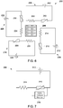
- FIG. 4 is a circuit diagram of an exemplary alternative heating circuit 108 for use in the passive heating system 100 of FIG. 1 including a negative temperature coefficient (NTC) thermistor 110.
- FIG. 5 is an exemplary temperature performance curve 120 of NTC thermistor 110 shown in FIG. 4 .
- the x-axis of performance curve 120 represents the temperature of thermistor 110.
- the y-axis of performance curve 120 represents the resistance of thermistor 110.
- heating circuit 108 includes a current source 118 configured to provide a constant current to NTC thermistor 110 irrespective of varying resistance of NTC thermistor 110.
- current source 118 is electrically coupled to power supply unit 102 (shown in FIG. 1 ).
- the resistance of NTC thermistor 110 is less than R E Ohms.
- R E Ohms is less than 10 percent of the maximum potential resistance of NTC thermistor 110.
- R N Ohms is greater than 60 percent of the maximum potential resistance of NTC thermistor 110. More particularly, in the exemplary embodiment R N Ohms is greater than 80 percent of the maximum potential resistance of NTC thermistor 110.
- FIG. 6 is a schematic view of an exemplary passive heating system 200 including a plurality of exemplary heating circuits 208, 218, 228, 238.
- plurality of heating circuits 208, 218, 228, 238 are arranged around a temperature-sensitive electronic component 206.
- passive heating system 200 includes four heating circuits 208, 218, 228, 238.
- passive heating system 200 includes any number of heating circuits that enables passive heating system 200 to function as described herein.
- each heating circuit 208, 218, 228, 238 includes a constant voltage source 212, 222, 232, 242, a PTC thermistor 210, 220, 230, 240, and a resistor 214, 224, 234, 244.
- each heating circuit 208, 218, 228, 238 including a constant current heating circuit as described above.
- each heating circuit 208, 218, 228, 238 includes an NTC thermistor.
- passive heating system 200 includes at least one constant current circuit having an NTC thermistor and at least one constant potential circuit having a PTC thermistor.
- Resistors 214, 224, 234, 244 of each heating circuit 208, 218, 228, 238 are positioned adjacent temperature-sensitive electronic component 206.
- resistors 214, 224, 234, 244 are each directly coupled to temperature-sensitive electronic component 206 to facilitate thermal conduction between resistors 214, 224, 234, 244 and temperature-sensitive electronic component 206.
- resistors 214, 224, 234, 244 are equidistantly spaced around temperature-sensitive electronic component 206 to provide for evenly distributed thermal conduction between resistors 214, 224, 234, 244 and temperature-sensitive electronic component 206.
- thermistors 210, 220, 230, 240 are also directly coupled to temperature-sensitive electronic component 206 to facilitate thermal conduction between temperature-sensitive electronic component 206 and thermistors 210, 220, 230, 240. Coupling thermistors 210, 220, 230, 240 in thermal conduction with temperature-sensitive electronic component 206 ensures that the temperature of thermistors 210, 220, 230, 240 will be closely linked with the temperature of temperature-sensitive electronic component 206.
- heating circuits 208, 218, 228, 238 are arranged about temperature-sensitive electronic component 206 in any manner that facilitates efficient heating of temperature-sensitive electronic component 206 when temperature-sensitive electronic component 206 approaches the threshold temperature.
- heating circuits 208, 218, 228, 238 are positioned a distance from temperature-sensitive electronic component 206 and are arranged to facilitate efficient convective thermal transfer between heating circuits 208, 218, 228, 238 and temperature-sensitive electronic component 206.
- each thermistor 210, 220, 230, 240 has the same critical temperature.
- thermistors 210, 220, 230, 240 may have different critical temperatures from one another.
- critical temperatures of thermistors 210, 220, 230, 240 are staggered such that heating circuits 208, 218, 228, 238 each begin to generate heat at different times as the ambient environmental temperature drops.
- plurality of heating circuits 208, 218, 228, 238 may serve as backups for one another that generate heat only after temperature of the temperature-sensitive electronic component 206 continues to fall after other heating circuits 208, 218, 228, 238 have begun generating heat.
- each heating circuit 208, 218, 228, 238 is electrically coupled to a single voltage source.
- heating circuit 308 is substantially similar to heating circuit 108 described above with respect to FIG. 2 including voltage monitor 316 electrically connected in parallel with a PTC thermistor 310 and configured to measure the voltage change through PTC thermistor 310. That is, in the exemplary embodiment, heating circuit 308 includes PTC thermistor 310, a voltage source 312 and a resistor 314 electrically connected in series. In alternative embodiments, heating circuit 308 is substantially similar to heating circuit 108 described above with respect to FIG. 4 . That is, in alternative embodiments, heating circuit 308 includes an NTC thermistor 110 and a current source 118 (shown in FIG. 4 ). In the exemplary embodiment, current monitor 316 is arranged to sense the current through PTC thermistor 310.
- current monitor 316 is operable to sense a flow of current through PTC thermistor 310 and generate an electrical response based on whether PTC thermistor 310 is in an open circuit state or a short circuit state.
- PTC thermistor 310 may be susceptible to degradation and failure during use of heating circuit 308. Failure of PTC thermistor 310 can result in PTC thermistor 310 having a near zero electrical impedance irrespective of a surrounding temperature (e.g., a short circuit failure). During a short-circuit failure of heating circuit 308, thermistor will provide near zero resistance, thereby causing resistor 314 to generate heat irrespective of the ambient temperature.
- delta voltage monitor 316 detects a voltage drop through PTC thermistor 310 of substantially near zero, an open circuit is created through the current monitor 316 to stop the flow of current through heating circuit 308. Ceasing the flow of current through heating circuit 308 prevents overheating of temperature-sensitive electronic component 106 (shown in FIG. 1 ).
- delta voltage monitor 316 includes an exterior indicator (not shown) to indicate that delta voltage monitor 316 has created an open circuit. Accordingly, in alternative embodiments, the fact that heating circuit 308 has a failed PTC thermistor 310 may be quickly identified during routine checks and replaced with a properly functioning heating circuit 308 or PTC thermistor 310.
- delta voltage monitor 316 further includes an open circuit indicator to indicate a failure of PTC thermistor 310 resulting in an open circuit. For example, degradation of PTC thermistor 310 can also cause PTC thermistor 310 to create an open circuit, thereby preventing the flow of current through heating circuit 308 and preventing resistor 314 from generating heat irrespective of the ambient temperature. Delta voltage monitor 316 indicates an open circuit whenever delta voltage monitor 316 senses a voltage drop below the material threshold of delta voltage monitor 316. Accordingly, heating circuit 308 with a PTC thermistor 310 having an open circuit failure may be identified during routine checks and replaced with a properly functioning heating circuit 308 or PTC thermistor 310.
- passive heating system 100 includes at least one additional heating circuit (not shown) substantially identical to heating circuit 308.
- the at least one redundant heating circuit continues to provide heat to temperature-sensitive electronic component 106 (shown in FIG. 1 ) after either delta voltage monitor 316 creates an open circuit due to a short circuit through PTC thermistor 310 or delta voltage monitor 316 detects an open circuit through PTC thermistor 310.
- delta voltage monitor 316 is connected to redundant heating circuits (not shown) such that detection of an open circuit or short circuit through PTC thermistor 310 triggers current flow through the redundant heating circuit (not shown) to enable the redundant heating circuit to provide heat when heating circuit 308 is in a state of failure and to not provide heat when heating circuit 308 is not in a state of failure.
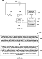
- FIG. 8 is a schematic view of an alternative exemplary heating circuit 308 for use in passive heating system 100 of FIG. 1 including current monitor 316 and a controller 318.
- delta voltage monitor 316 is communicatively coupled to controller 318 such that delta voltage monitor 316 relays the sensed voltage drop to controller 318.
- controller 318 includes a memory device 320 and a processor 322 coupled to memory device 320.
- Processor 322 may include one or more processing units, such as, without limitation, a multi-core configuration.
- Processor 322 is any type of processor that permits controller 318 to operate as described herein.
- executable instructions are stored in memory device 320.
- Controller 318 is configurable to perform one or more operations described herein by programming processor 322.
- processor 322 may be programmed by encoding an operation as one or more executable instructions and providing the executable instructions in memory device 320.
- memory device 320 is one or more devices that enable storage and retrieval of information such as executable instructions or other data.
- Memory device 320 may include one or more computer readable media, such as, without limitation, random access memory (RAM), dynamic RAM, static RAM, a solid-state disk, a hard disk, read-only memory (ROM), erasable programmable ROM, electrically erasable programmable ROM, or non-volatile RAM memory.
- RAM random access memory
- dynamic RAM dynamic RAM
- static RAM static RAM
- solid-state disk such as solid-state disk
- hard disk such as hard disk
- ROM read-only memory
- ROM read-only memory
- erasable programmable ROM electrically erasable programmable ROM
- non-volatile RAM memory such as, without limitation, random access memory (RAM), dynamic RAM, static RAM, a solid-state disk,
- Memory device 320 may be configured to store any type of data, including, without limitation, voltage drop parameters relayed by delta voltage monitor 316.
- processor 322 removes or "purges" data from memory device 320 based on the age of the data. For example, processor 322 may overwrite previously recorded and stored data associated with a subsequent time or event. In addition, or alternatively, processor 322 may remove data that exceeds a predetermined time interval.
- FIG. 9 is a flowchart of an exemplary method 400 of retrofitting a system 100, shown in FIG. 1 , for operation below a threshold temperature.
- Method 400 includes positioning 402 at least one passive resistive heating element (e.g., heating circuit 108, shown in FIG. 1 ) proximate at least one temperature-sensitive electronic component 106, shown in FIG. 1 , of system 100, the at least one temperature-sensitive electronic component 106 becoming susceptible to failure when the temperature of the temperature-sensitive electronic component 106 decreases and crosses the threshold temperature.
- Method 400 also includes electrically coupling 404 the at least one passive resistive heating element 108 to power supply 102, shown in FIG. 1 , the at least one passive resistive heating element 108 configured to generate heat energy when an ambient temperature of the at least one passive resistive heating element 108 decreases and approaches the threshold temperature in order to maintain the temperature of the temperature-sensitive electronic component 106 above the threshold temperature.
- Exemplary technical effects of the passive heating system described herein include, for example: (a) increasing reliability of temperature-sensitive electronic components; (b) increasing lifespan of temperature-sensitive electronic components operating in extreme temperature environments; (c) reducing complexity in temperature-sensitive electronic component heating systems; (d) increasing ability to target thermal conduction on individual electronic components of electronic systems.
Landscapes
- Physics & Mathematics (AREA)
- Engineering & Computer Science (AREA)
- Thermal Sciences (AREA)
- Microelectronics & Electronic Packaging (AREA)
- General Physics & Mathematics (AREA)
- Automation & Control Theory (AREA)
- Control Of Resistance Heating (AREA)
- Air-Conditioning For Vehicles (AREA)
Abstract
Description
- The disclosure relates to a system for operation below a threshold temperature and more specifically to the system having a temperature-sensitive electronic component.
- The subject matter disclosed herein relates generally to systems and methods for passively heating temperature-sensitive electronic components, and, more particularly, to systems and methods for passively maintaining a temperature of one or more electronic components above a minimum operating temperature during cold temperature operation.
- Many aerospace and terrestrial systems incorporate a variety of complex internal electronic systems, such as, for example, guidance systems, navigation systems, power systems, and the like. During operation, these systems may be subjected to a variety of environmental extremes, such as, for example, extreme high and low temperatures and/or rapid fluctuations in a variety of environmental conditions, such as temperature, humidity, and pressure.
- As a result, many conventional aerospace and terrestrial systems may include one or more environmental control systems arranged to protect sensitive internal electronic hardware and circuitry from surrounding environmental conditions. Commonly, however, these environmental control systems require additional environmental shielding and/or control systems of their own. In addition, many conventional environmental control systems are themselves quite complex and may require substantial time and financial expenditure for their design and implementation. An additional drawback is that such systems may, as a result of their complexity, fail unexpectedly and/or require periodic maintenance.
- For instance, many aerospace systems are designed for high altitude cold temperature operation. However, certain electronic components, such as one or more off-the-shelf microprocessors, may require a temperature-controlled internal environment for proper operation. To this end, a typical aerospace system may include a stand-alone environmental control system, which may itself rely upon temperature measurements and/or calculations obtained by and/or processed by one or more dedicated electronic components (e.g., temperature sensors, microcontrollers, etc.)
- In one aspect, a system configured for operation below a threshold temperature is provided. The system includes a power supply, a housing, a temperature-sensitive electronic component, and a heating circuit. The temperature-sensitive electronic component is enclosed within the housing and electrically connected to the power supply, the temperature-sensitive electronic component becomes susceptible to failure when the temperature of the temperature-sensitive electronic component decreases and crosses the threshold temperature. The heating circuit is at least partially enclosed within the housing and comprises a temperature-dependent resistor, the heating circuit electrically connected to the power supply and configured to generate heat energy within the housing when the temperature within the housing decreases and approaches the threshold temperature in order to maintain the temperature of the temperature-sensitive electronic component above the threshold temperature.
- In another aspect, a system configured for operation below a threshold temperature is provided. The system includes at least one temperature-sensitive electronic component and at least one passive resistive heating element. The at least one temperature-sensitive electronic component becoming susceptible to failure when the temperature of the at least one temperature-sensitive electronic component decreases and crosses the threshold temperature. The at least one passive resistive heating element configured to generate heat energy when an ambient temperature of the at least one passive resistive heating element decreases and approaches the threshold temperature the threshold temperature in order to maintain the temperature of the at least one temperature-sensitive electronic component above the threshold temperature.
- These and other features, aspects, and advantages of the present disclosure will become better understood when the following detailed description is read with reference to the accompanying drawings in which like characters represent like parts throughout the drawings, wherein:
-
FIG. 1 is a block diagram of an exemplary passive heating system; -
FIG. 2 is a circuit diagram of an exemplary heating circuit for use in the passive heating system ofFIG. 1 including a positive temperature coefficient thermistor; -
FIG. 3 is an exemplary temperature performance curve of the positive temperature coefficient thermistor shown inFIG. 2 ; -
FIG. 4 is a circuit diagram of an alternative exemplary heating circuit for use in the passive heating system ofFIG. 1 including a negative temperature coefficient thermistor; -
FIG. 5 is an exemplary temperature performance curve of the negative temperature coefficient thermistor shown inFIG. 4 ; -
FIG. 6 is a schematic view of an exemplary passive heating system including a plurality of the exemplary heating circuits shown inFIG. 2 ; -
FIG. 7 is a circuit diagram of an alternative exemplary heating circuit for use in the passive heating system ofFIG. 1 including a current monitor; -
FIG. 8 is a schematic view of an alternative exemplary heating circuit for use in the passive heating system ofFIG. 1 including a current monitor and a controller; and -
FIG. 9 is a flowchart of an exemplary method of retrofitting a system for operation below a threshold temperature. - Unless otherwise indicated, the drawings provided herein are meant to illustrate features of embodiments of the disclosure. These features are believed to be applicable in a wide variety of systems comprising one or more embodiments of the disclosure. As such, the drawings are not meant to include all conventional features known by those of ordinary skill in the art to be required for the practice of the embodiments disclosed herein.
- In the following specification and the claims, reference will be made to a number of terms, which shall be defined to have the following meanings.
- The singular forms "a", "an", and "the" include plural references unless the context clearly dictates otherwise.
- "Optional" or "optionally" means that the subsequently described event or circumstance may or may not occur, and that the description includes instances where the event occurs and instances where it does not.
- As used herein, the phrase "generate heat energy" means that generator produces at least 0.1 watts of heat energy.
- As used herein, the terms "processor" and "computer," and related terms, e.g., "processing device," "computing device," and "controller" are not limited to just those integrated circuits referred to in the art as a computer, but broadly refers to a microcontroller, a microcomputer, a programmable logic controller (PLC), and application specific integrated circuit, and other programmable circuits, and these terms are used interchangeably herein. In the embodiments described herein, memory may include, but it not limited to, a computer-readable medium, such as a random access memory (RAM), a computer-readable non-volatile medium, such as a flash memory. Alternatively, other computer peripherals may also be used that may include, for example, but not be limited to, a scanner. Furthermore, in the exemplary embodiment, additional output channels may include, but not be limited to, an operator interface monitor.
- Approximating language, as used herein throughout the specification and claims, may be applied to modify any quantitative representation that could permissibly vary without resulting in a change in the basic function to which it is related. Accordingly, a value modified by a term or terms, such as "about" and "substantially", are not to be limited to the precise value specified. In at least some instances, the approximating language may correspond to the precision of an instrument for measuring the value. Here and throughout the specification and claims, range limitations may be combined and/or interchanged, such ranges are identified and include all the sub-ranges contained therein unless context or language indicates otherwise.
- Exemplary embodiments of passive heating systems and methods are described herein. The exemplary passive heating systems described herein include a housing and a temperature-sensitive electronic component enclosed within the housing. The temperature-sensitive electronic component is electrically connected to a power supply. The temperature-sensitive electronic component is designed for reliable operation above a threshold temperature. Specifically, the temperature-sensitive electronic component is susceptible to failure at an increased rate when the electronic component is operated below the threshold temperature. The passive heating system further includes a heating circuit at least partially enclosed within the housing. The heating circuit includes a temperature-dependent resistor electrically connected to the power supply. The heating circuit is configured to generate heat energy within the housing when the temperature within the housing decreases and approaches the threshold temperature in order to maintain the temperature of the temperature-sensitive electronic component above the threshold temperature.
-
FIG. 1 is a block diagram of an exemplarypassive heating system 100.Passive heating system 100 includes apower supply unit 102, ahousing 104, and a temperature-sensitiveelectronic component 106 enclosed withinhousing 104. In the exemplary embodiment, temperature-sensitiveelectronic component 106 is an electronic component for use in an onboard computing system of an aerospace device or vehicle. For example, temperature-sensitiveelectronic component 106 may be an electronic component in a remote interface unit (RIU) system of an aerospace device or vehicle. More specifically, in the exemplary embodiment, temperature-sensitiveelectronic component 106 is a microprocessor for use in a RIU system. In alternative embodiments, temperature-sensitiveelectronic component 106 may be individual electronic components included in a microprocessor of an RIU system. In even further embodiments, temperature-sensitiveelectronic component 106 is any electronic component that enablespassive heating system 100 to function as described herein. - In the exemplary embodiment, temperature-
sensitive component 106 is electrically connected topower supply 102. Temperature-sensitiveelectronic component 106 is configured for operation above a threshold temperature. In particular, temperature-sensitiveelectronic component 106 is configured to consistently and reliably operate above a manufacturer-specified threshold temperature. Accordingly, temperature-sensitiveelectronic component 106 is susceptible to a higher probability of failure when operating in an environment having an ambient temperature below the threshold temperature. -
Passive heating system 100 further includes aheating circuit 108 including a temperature-dependent resistor, such as athermistor 110, enclosed withinhousing 104 and electrically connected topower supply unit 102. In the exemplary embodiment,power supply unit 102 is located outside ofhousing 104. In alternative embodiments,power supply unit 102 is located withinhousing 104. In the exemplary embodiment,power supply unit 102 supplies direct current (DC) power toheating circuit 108 and temperature-sensitive component 106. In alternative embodiments,power supply unit 102 includes any voltage source that enablespassive heating system 100 to function as described herein. For example, in alternative embodiments,power supply unit 102 includes multiple voltage sources such as 5 Volt, 12 Volt, and 28 Volt buses configured to provide direct current power. In such embodiments,heating circuit 108 is electrically coupled to the 12 Volt bus and temperature-sensitiveelectronic component 106 is electrically coupled to the 28 Volt bus. In other embodiments,heating circuit 108 is configured to be electrically coupled to any power supply that enablespassive heating system 100 to function as described herein. In alternative embodiments,heating circuit 108 is connected to a differentpower supply unit 102 than temperature-sensitiveelectronic component 106. - In the exemplary embodiment,
housing 104 enclosesheating circuit 108 and temperature-sensitiveelectronic component 106 such that heat radiated byheating circuit 108 is at least partially captured and contained withinhousing 104 to facilitate heating of temperature-sensitiveelectronic component 106. In the exemplary embodiment, temperature-sensitiveelectronic component 106 andthermistor 110 are each coupled to a printed circuit board (not shown) and are physically coupled directly to one another to facilitate thermal conduction between temperature-sensitiveelectronic component 106 andthermistor 110. In alternative embodiments,thermistor 110 is spaced from and located proximate to temperature-sensitiveelectronic component 106 to facilitate efficient convective thermal exchange between temperature-sensitiveelectronic component 106 andthermistor 110. In the exemplary embodiment,housing 104 includes a plastic outer covering and a thermal insulation material between the plastic outer covering and the printed circuit board. The thickness ofhousing 104 facilitates capturing generated heat withinhousing 104 while preventing overheating of components withinhousing 104. In other embodiments,housing 104 includes no thermal insulation material. Alternatively,housing 104 is composed of any material that enablespassive heating system 100 to function as described herein. - In the exemplary embodiment,
heating circuit 108 is configured to generate heat energy when the temperature withinhousing 104 decreases and approaches the threshold temperature, such that the temperature of temperature-sensitiveelectronic component 106 is maintained above the threshold temperature. In the exemplary embodiment,thermistor 110 ofheating circuit 108 is composed of a ceramic material having a temperature-dependent resistance. In alternative embodiments,thermistor 110 is composed of a polymer. In even further embodiments,thermistor 110 is composed of any material that enablesthermistor 110 to function as described herein.Thermistor 110 has a varying resistance depending on the ambient environmentaltemperature surrounding thermistor 110. In particular, as will be described in greater detail with respect toFIG. 3 ,thermistor 110 is configured to change its resistance when the ambient temperature reaches a critical temperature ofthermistor 110. - In the exemplary embodiment, when
thermistor 110 is electrically coupled topower supply unit 102, a change in the ambient environmentaltemperature surrounding thermistor 110 effects a change in the total resistance ofheating circuit 108. Accordingly, in the exemplary embodiment, a change in the ambient environmentaltemperature surrounding thermistor 110 causes a change in the total heat energy output byheating circuit 108. In particular,thermistor 110 is configured to causeheating circuit 108 to substantially increase generation of heat energy when a temperature ofthermistor 110 is less than the critical temperature ofthermistor 110. - As described in greater detail with respect to
FIGS. 2-5 ,heating circuit 108 may have different configurations that enable the resistance change ofthermistor 110 to result inheating circuit 108 generating heat energy. For example, in some embodiments ofheating circuit 108,thermistor 110 itself generates heat energy by increasing in resistance when the temperature ofthermistor 110 decreases and approaches the threshold temperature. In other embodiments ofheating circuit 108,thermistor 110 does not substantially increase generated heat energy, but instead causes a change in current flow throughheating circuit 108 which causes a separate resistor ofheating circuit 108 to generate additional heat energy. In particular, in such embodiments,thermistor 110 decreases in resistance when the temperature ofthermistor 110 decreases and approaches the threshold temperature. Accordingly, in such embodiments ofheating circuit 108, the decrease in resistance ofthermistor 110 causes an increase in current flowing throughheating circuit 108, which in turn causes a separate resistor wired in series withthermistor 110 to generate heat energy. - In the exemplary embodiment,
thermistor 110 is configured such that the critical temperature ofthermistor 110 is less than the threshold temperature of temperature-sensitiveelectronic component 106. Accordingly, when the temperature ofthermistor 110 is greater than the threshold temperature of temperature-sensitive electronic component 106 (i.e., also above the critical temperature of thermistor),heating circuit 108 generates substantially no heat energy. Therefore, in the exemplary embodiment,heating circuit 108 is incapable of over-heating temperature-sensitiveelectronic component 106. Furthermore, when the ambient temperature decreases and crosses the threshold temperature of temperature-sensitiveelectronic component 106, the temperature ofthermistor 110 also drops below the critical temperature, causingheating circuit 108 to substantially increase generation of heat energy, and thereby maintain the temperature of temperature-sensitiveelectronic component 106 at a temperature above the threshold temperature of temperature-sensitiveelectronic component 106. - In some alternative embodiments, the critical temperature of
thermistor 110 differs from the threshold temperature of temperature-sensitiveelectronic component 106 such thatheating circuit 108 generates heat energy when a temperature ofthermistor 110 is within a range of temperatures running from a temperature less than the threshold temperature to a temperature greater than the threshold temperature. In these embodiments,heating circuit 108 is configured to increase generation of heat energy as the temperature ofthermistor 110 moves from the upper end of the temperature range to the lower end of the temperature range. In the exemplary embodiment, the minimum and the critical temperature ofthermistor 110 are approximately equal to minus forty degrees Celsius (-40° C). In alternative embodiments, the threshold temperature and the critical temperature are any temperatures that enablepassive heating system 100 to function as described herein. -
FIG. 2 is a circuit diagram of anexemplary heating circuit 108 for use in passive heating system 100 (shown inFIG. 1 ).FIG. 3 is an exemplary temperature performance curve 116 of a positivetemperature coefficient thermistor 110 shown inFIG. 2 . The x-axis of performance curve 116 represents the temperature ofthermistor 110. The y-axis of performance curve 116 represents the resistance ofthermistor 110. Referring toFIG. 2 , in the exemplary embodiment,heating circuit 108 includes avoltage source 112. In the exemplary embodiment,voltage source 112 is power supply unit 102 (shown inFIG. 1 ). In alternative embodiments,voltage source 112 is an alternative power source that is powered bypower supply unit 102.Heating circuit 108 further includes aresistor 114 andthermistor 110 electrically coupled in series withvoltage source 112. - In the exemplary embodiment,
voltage source 112 is a constant potential source that maintains a constant voltage supply independent of any changing resistive load onheating circuit 108.Thermistor 110 is a positive-temperature-coefficient (PTC)thermistor 110 configured to decrease its electrical resistance as the ambienttemperature surrounding thermistor 110 decreases and increase its electrical resistance as the temperature aroundthermistor 110 increases.Resistor 114 is configured to maintain a substantially fixed resistance irrespective of changes in temperature. Accordingly, in the exemplary embodiment, when the temperature ofPTC thermistor 110 is above the critical temperature (i.e., the temperature is greater than TE as shown inFIG. 3 ), the resistance ofthermistor 110 is relatively high and current flowing throughresistor 114 andthermistor 110 is comparatively low as a result of the relatively high resistance ofthermistor 110. When the temperature ofPTC thermistor 110 falls below the critical temperature, however the resistance ofPTC thermistor 110 drops significantly. More specifically, referring toFIG. 3 , when the temperature ofPTC thermistor 110 drops below TE, the resistance ofthermistor 110 accordingly drops from RE Ohms to RN Ohms. With reference again toFIG. 2 , becausevoltage source 112 is a constant potential source, in the exemplary embodiment, the decrease in resistance ofPTC thermistor 110 to RN Ohms causes an increased current flow throughresistor 114 andPTC thermistor 110. - The heat generated by
resistor 114 is a function of the square of the current flow throughresistor 114 multiplied by the resistance ofresistor 114. Because the resistance ofresistor 114 is fixed, the change in current flow throughresistor 114, caused by the drop in resistance ofPTC thermistor 110 to RN Ohms, causesresistor 114 to generate heat energy. Furthermore, as a result of the increased current throughPTC thermistor 110,PTC thermistor 110 may also generate heat energy despite the drop in resistance. Accordingly, heat energy generated fromresistor 114 is increased when the current flow throughresistor 114 andthermistor 110 increases. - In the exemplary embodiment,
resistor 114 has a much higher resistance thanPTC thermistor 110 when the temperature ofPTC thermistor 110 is below the critical temperature. Thus, in the exemplary embodiment, heat generated byheating circuit 108 is primarily generated byresistor 114.PTC thermistor 110 therefore serves primarily to regulate the electric current throughheating circuit 108 and, in particular, the electric current through overresistor 114, depending on the temperature ofPTC thermistor 110. In the exemplary embodiment,thermistor 110 is spaced from resistor 114 a sufficient distance to prevent heat generated byresistor 114 from causing an ambient temperature ofthermistor 110 to rise above the general ambient temperature ofhousing 104. In certain embodiments,PTC thermistor 110 is spaced between 1 mm and 5 mm fromresistor 114. More particularly,PTC thermistor 110 is spaced at least .5 mm fromresistor 114. In alternative embodiments,PTC thermistor 110 is spaced any distance from resistor that enablespassive heating system 100 to function as described herein. In further alternative embodiments,heating circuit 108 includes only aPTC thermistor 110 electrically coupled tovoltage source 112. In such embodiments, heat generated byheating circuit 108 is generated solely byPTC thermistor 110. - Referring to
FIG. 3 , in performance curve 116,PTC thermistor 110 has a critical temperature in the range of TE to TN. TE represents the temperature at which the resistance begins to noticeably change. TN represents the temperature at which, below TN, the resistance ofthermistor 110 is stabilized at a low value. In the exemplary embodiment, when the temperature ofthermistor 110 is greater than TE, the resistance ofPTC thermistor 110 is at least greater than RE Ohms. In the exemplary embodiment, RE Ohms is at least 90 percent of the maximum possible resistance ofPTC thermistor 110. - As the temperature of
PTC thermistor 110 drops below TE, resistance ofthermistor 110 accordingly drops from RE Ohms to RN Ohms. In the exemplary embodiment, RN Ohms is less than 20 percent of the maximum possible resistance potential ofPTC thermistor 110. More particularly, in the exemplary embodiment RN Ohms is less than 5 percent of the maximum possible resistance ofPTC thermistor 110. As the temperature ofPTC thermistor 110 drops below TN, the resistance ofthermistor 110 stabilizes between RN Ohms and RA Ohms. In the exemplary embodiment, RN is 2000 Ohms and RE is 100 Ohms. In alternative embodiments, PTC thermistor has any value RN and RE defining any range that enablespassive heating system 100 to function as described herein. - The temperature difference between TE to TN impacts the rapidity with which
heating circuit 108 is able to generate heat. In other words, the smaller the difference between TE to TN, themore heating circuit 108 functions as a binary switch having a heating mode and an off mode. Conversely,PTC thermistors 110 having a larger difference between TE to TN allow for steady increases in heating. In the exemplary embodiment, TE is equal to -39° Celsius and TN is equal to -40° Celsius. That is, in the exemplary embodiment, where the threshold temperature of temperature-sensitiveelectronic component 106 is equal to -40° Celsius, TN is equal to the threshold temperature and TE is equal to one degree higher than the threshold temperature. In alternative embodiments, the difference between TE to TN may be between .01 degrees Celsius and 20 degrees Celsius. More particularly, the difference between TE to TN may range between 1 degree and 5 degrees. In even further embodiments, TE to TN defines any range that enablespassive heating system 100 to function as described herein. - In the exemplary embodiment, the total heat generated by
heating circuit 108, the relationship between changes in temperature to changes in heat generated, and the critical temperature ofthermistor 110 are all determined by physical characteristics ofheating circuit 108. For example, in alternative embodiments,heating circuit 108 includesmultiple PTC thermistors 110 and/orresistors 114 wired in parallel withPTC thermistor 110 andresistor 114. Accordingly, in these embodiments, the ratio of a decrease in temperature to heat generated byheating circuit 108 is increased relative the exemplary embodiment. Further, the critical temperature ofthermistor 110 is determined by the material composition ofthermistor 110. Accordingly,thermistor 110 may be selected based on the desired critical temperature ofthermistor 110 depending on the application. As a result,passive heating system 100 allows for thermal regulation of temperature-sensitive electronic components without requiring a controller or computer-executed software. -
FIG. 4 is a circuit diagram of an exemplaryalternative heating circuit 108 for use in thepassive heating system 100 ofFIG. 1 including a negative temperature coefficient (NTC)thermistor 110.FIG. 5 is an exemplary temperature performance curve 120 ofNTC thermistor 110 shown inFIG. 4 . The x-axis of performance curve 120 represents the temperature ofthermistor 110. The y-axis of performance curve 120 represents the resistance ofthermistor 110. In the exemplary embodiment,heating circuit 108 includes acurrent source 118 configured to provide a constant current toNTC thermistor 110 irrespective of varying resistance ofNTC thermistor 110. In the exemplary embodiment,current source 118 is electrically coupled to power supply unit 102 (shown inFIG. 1 ). - Referring to
FIG. 5 , in the exemplary embodiment,NTC thermistor 110 is configured to decrease its resistance as the ambient temperature aroundthermistor 110 increases. Accordingly, in the exemplary embodiment, when the temperature ofNTC thermistor 110 is above a critical temperature TE, the resistance RE ofthermistor 110 is relatively low. As the temperature ofNTC thermistor 110 drops below the critical temperature TE ofNTC thermistor 110, the resistance ofthermistor 110 increases from RE Ohms to RN Ohms. Accordingly, in the exemplary performance curve,NTC thermistor 110 has a critical temperature in the range of TE to TN, with TE representing the temperature at which the resistance begins to noticeably change and TN representing the temperature at which, below TN, the resistance ofthermistor 110 is stabilized at a high value. - In the exemplary embodiment, when the temperature of
thermistor 110 is greater than TE, the resistance ofNTC thermistor 110 is less than RE Ohms. In the exemplary embodiment, RE Ohms is less than 10 percent of the maximum potential resistance ofNTC thermistor 110. In the exemplary embodiment, RN Ohms is greater than 60 percent of the maximum potential resistance ofNTC thermistor 110. More particularly, in the exemplary embodiment RN Ohms is greater than 80 percent of the maximum potential resistance ofNTC thermistor 110. - In the exemplary embodiment, TE is equal to -39 degrees Celsius and TN is equal to -40 degrees Celsius. That is, in the exemplary embodiment, where the threshold temperature of the temperature-sensitive
electronic component 106 is equal to - 40 degrees Celsius, TN is equal to the threshold temperature and TE is equal to one degree higher than the threshold temperature. In alternative embodiments, the difference between TE to TN may be between .01 degrees Celsius and 20 degrees Celsius. More particularly, the difference between TE to TN may range between 1 degree and 5 degrees. In even further embodiments, TE to TN defines any range that enablespassive heating system 100 to function as described herein. - Referring to
FIG. 4 , sincecurrent source 118 is a constant current source, the increase in resistance ofNTC thermistor 110 from RE Ohms to RN Ohms causes a corresponding increase in heat generated byNTC thermistor 110. That is, since the heat generated byNTC thermistor 110 is a function of the square of the current overthermistor 110 multiplied by the resistance ofthermistor 110, and since the current is maintained at a constant value bycurrent source 118, increasing the resistance ofNTC thermistor 110 increases the heat generated byheating circuit 108, and, more particularly,NTC thermistor 110. -
FIG. 6 is a schematic view of an exemplarypassive heating system 200 including a plurality ofexemplary heating circuits heating circuits electronic component 206. In particular,passive heating system 200 includes fourheating circuits passive heating system 200 includes any number of heating circuits that enablespassive heating system 200 to function as described herein. - In the exemplary embodiment, each
heating circuit constant voltage source PTC thermistor resistor heating circuit heating circuit passive heating system 200 includes at least one constant current circuit having an NTC thermistor and at least one constant potential circuit having a PTC thermistor. -
Resistors heating circuit electronic component 206. In the exemplary embodiment,resistors electronic component 206 to facilitate thermal conduction betweenresistors electronic component 206. Furthermore,resistors electronic component 206 to provide for evenly distributed thermal conduction betweenresistors electronic component 206. In the exemplary embodiment,thermistors electronic component 206 to facilitate thermal conduction between temperature-sensitiveelectronic component 206 andthermistors thermistors electronic component 206 ensures that the temperature ofthermistors electronic component 206. In alternative embodiments,heating circuits electronic component 206 in any manner that facilitates efficient heating of temperature-sensitiveelectronic component 206 when temperature-sensitiveelectronic component 206 approaches the threshold temperature. For example, in other embodiments,heating circuits electronic component 206 and are arranged to facilitate efficient convective thermal transfer betweenheating circuits electronic component 206. - In the exemplary embodiment, each
thermistor thermistors thermistors heating circuits heating circuits electronic component 206 continues to fall afterother heating circuits heating circuit -
FIG. 7 is a schematic view of an alternativeexemplary heating circuit 308 for use inpassive heating system 100 ofFIG. 1 including acurrent monitor 316. In alternative embodiments,heating circuit 308 is used in any passive heating system that enablesheating circuit 308 to function as described herein. For example, in alternative embodiments,heating circuit 308 is used in apassive heating system 200 ofFIG. 6 . In the exemplary embodiment,current monitor 316 includes a standard fuse arranged to create an open circuit whenever the electrical current throughcurrent monitor 316 exceeds a material dependent threshold of the fuse. In alternative embodiments,current monitor 316 includes anycurrent monitor 316 that enablesheating circuit 308 to function as described herein. - In the exemplary embodiment,
heating circuit 308 is substantially similar toheating circuit 108 described above with respect toFIG. 2 including voltage monitor 316 electrically connected in parallel with aPTC thermistor 310 and configured to measure the voltage change throughPTC thermistor 310. That is, in the exemplary embodiment,heating circuit 308 includesPTC thermistor 310, avoltage source 312 and aresistor 314 electrically connected in series. In alternative embodiments,heating circuit 308 is substantially similar toheating circuit 108 described above with respect toFIG. 4 . That is, in alternative embodiments,heating circuit 308 includes anNTC thermistor 110 and a current source 118 (shown inFIG. 4 ). In the exemplary embodiment,current monitor 316 is arranged to sense the current throughPTC thermistor 310. - In the exemplary embodiment,
current monitor 316 is operable to sense a flow of current throughPTC thermistor 310 and generate an electrical response based on whetherPTC thermistor 310 is in an open circuit state or a short circuit state. For example,PTC thermistor 310 may be susceptible to degradation and failure during use ofheating circuit 308. Failure ofPTC thermistor 310 can result inPTC thermistor 310 having a near zero electrical impedance irrespective of a surrounding temperature (e.g., a short circuit failure). During a short-circuit failure ofheating circuit 308, thermistor will provide near zero resistance, thereby causingresistor 314 to generate heat irrespective of the ambient temperature. Accordingly, if left uncorrected, a short circuit failure could lead to overheating of temperature-sensitive electronic component 106 (shown inFIG. 1 ). In the exemplary embodiment, when delta voltage monitor 316 detects a voltage drop throughPTC thermistor 310 of substantially near zero, an open circuit is created through thecurrent monitor 316 to stop the flow of current throughheating circuit 308. Ceasing the flow of current throughheating circuit 308 prevents overheating of temperature-sensitive electronic component 106 (shown inFIG. 1 ). In alternative embodiments, delta voltage monitor 316 includes an exterior indicator (not shown) to indicate that delta voltage monitor 316 has created an open circuit. Accordingly, in alternative embodiments, the fact thatheating circuit 308 has a failedPTC thermistor 310 may be quickly identified during routine checks and replaced with a properly functioningheating circuit 308 orPTC thermistor 310. - In the exemplary embodiment, delta voltage monitor 316 further includes an open circuit indicator to indicate a failure of
PTC thermistor 310 resulting in an open circuit. For example, degradation ofPTC thermistor 310 can also causePTC thermistor 310 to create an open circuit, thereby preventing the flow of current throughheating circuit 308 and preventingresistor 314 from generating heat irrespective of the ambient temperature. Delta voltage monitor 316 indicates an open circuit whenever delta voltage monitor 316 senses a voltage drop below the material threshold of delta voltage monitor 316. Accordingly,heating circuit 308 with aPTC thermistor 310 having an open circuit failure may be identified during routine checks and replaced with a properly functioningheating circuit 308 orPTC thermistor 310. - In alternative embodiments, similar to
passive heating system 200 shown inFIG. 6 ,passive heating system 100 includes at least one additional heating circuit (not shown) substantially identical toheating circuit 308. For example, in such embodiments, the at least one redundant heating circuit (not shown) continues to provide heat to temperature-sensitive electronic component 106 (shown inFIG. 1 ) after either delta voltage monitor 316 creates an open circuit due to a short circuit throughPTC thermistor 310 or delta voltage monitor 316 detects an open circuit throughPTC thermistor 310. In even further alternative embodiments, delta voltage monitor 316 is connected to redundant heating circuits (not shown) such that detection of an open circuit or short circuit throughPTC thermistor 310 triggers current flow through the redundant heating circuit (not shown) to enable the redundant heating circuit to provide heat whenheating circuit 308 is in a state of failure and to not provide heat whenheating circuit 308 is not in a state of failure. -
FIG. 8 is a schematic view of an alternativeexemplary heating circuit 308 for use inpassive heating system 100 ofFIG. 1 includingcurrent monitor 316 and acontroller 318. In the exemplary embodiment, delta voltage monitor 316 is communicatively coupled tocontroller 318 such that delta voltage monitor 316 relays the sensed voltage drop tocontroller 318. In the exemplary embodiment,controller 318 includes amemory device 320 and aprocessor 322 coupled tomemory device 320.Processor 322 may include one or more processing units, such as, without limitation, a multi-core configuration.Processor 322 is any type of processor that permitscontroller 318 to operate as described herein. In some embodiments, executable instructions are stored inmemory device 320.Controller 318 is configurable to perform one or more operations described herein byprogramming processor 322. For example,processor 322 may be programmed by encoding an operation as one or more executable instructions and providing the executable instructions inmemory device 320. In the exemplary embodiment,memory device 320 is one or more devices that enable storage and retrieval of information such as executable instructions or other data.Memory device 320 may include one or more computer readable media, such as, without limitation, random access memory (RAM), dynamic RAM, static RAM, a solid-state disk, a hard disk, read-only memory (ROM), erasable programmable ROM, electrically erasable programmable ROM, or non-volatile RAM memory. The above memory types are exemplary only, and are thus not limiting as to the types of memory usable for storage of a computer program. -
Memory device 320 may be configured to store any type of data, including, without limitation, voltage drop parameters relayed by delta voltage monitor 316. In some embodiments,processor 322 removes or "purges" data frommemory device 320 based on the age of the data. For example,processor 322 may overwrite previously recorded and stored data associated with a subsequent time or event. In addition, or alternatively,processor 322 may remove data that exceeds a predetermined time interval. - In the exemplary embodiment,
controller 318 determines and tracks current throughPTC thermistor 310 over time based on voltage drop sensed by delta voltage monitor. Further, in the exemplary embodiment, areference temperature sensor 324 is communicatively coupled tocontroller 318.Reference temperature sensor 324 is configured to relay a sensed temperature tocontroller 318.Controller 318 may then determine whetherPTC thermistor 310 is operating within normal operating parameters ofPTC thermistor 310. For example,controller 318 compares the sensed temperature from thereference temperature sensor 324 to the determined current based on the voltage drop sensed by delta voltage monitor 316 to determine whether current throughPTC thermistor 310 matches the expected current based on the voltage supply and the ambient temperature. Accordingly,controller 318 may determine ifPTC thermistor 310 experiences a parameter drift effect in which the critical temperature ofPTC thermistor 310 is different from the expected critical temperature ofPTC thermistor 310. In alternative embodiments,controller 318 is further connected to an external display to relay a warning ifcontroller 318 determines thatPTC thermistor 310 is experiencing parameter drift. In even further alternative embodiments,controller 318 is configured to controlheating circuit 308 such thatcontroller 318 may alter the flow of current withinheating circuit 308 to compensate for the determined parameter drift ofPTC thermistor 310. -
FIG. 9 is a flowchart of anexemplary method 400 of retrofitting asystem 100, shown inFIG. 1 , for operation below a threshold temperature.Method 400 includes positioning 402 at least one passive resistive heating element (e.g.,heating circuit 108, shown inFIG. 1 ) proximate at least one temperature-sensitiveelectronic component 106, shown inFIG. 1 , ofsystem 100, the at least one temperature-sensitiveelectronic component 106 becoming susceptible to failure when the temperature of the temperature-sensitiveelectronic component 106 decreases and crosses the threshold temperature.Method 400 also includes electrically coupling 404 the at least one passiveresistive heating element 108 topower supply 102, shown inFIG. 1 , the at least one passiveresistive heating element 108 configured to generate heat energy when an ambient temperature of the at least one passiveresistive heating element 108 decreases and approaches the threshold temperature in order to maintain the temperature of the temperature-sensitiveelectronic component 106 above the threshold temperature. - Exemplary technical effects of the passive heating system described herein include, for example: (a) increasing reliability of temperature-sensitive electronic components; (b) increasing lifespan of temperature-sensitive electronic components operating in extreme temperature environments; (c) reducing complexity in temperature-sensitive electronic component heating systems; (d) increasing ability to target thermal conduction on individual electronic components of electronic systems.
- Exemplary embodiments of a passive heating system and related components are described above in detail. The system is not limited to the specific embodiments described herein, but rather, components of systems and/or steps of the methods may be utilized independently and separately from other components and/or steps described herein. For example, the configuration of components described herein may also be used in combination with other processes, and is not limited to practice with the systems and related methods as described herein. Rather, the exemplary embodiment can be implemented and utilized in connection with many applications where heating is desired.
- Although specific features of various embodiments of the present disclosure may be shown in some drawings and not in others, this is for convenience only. In accordance with the principles of the present disclosure, any feature of a drawing may be referenced and/or claimed in combination with any feature of any other drawing.
- This written description uses examples to disclose the embodiments of the present disclosure, including the best mode, and also to enable any person skilled in the art to practice the disclosure, including making and using any devices or systems and performing any incorporated methods. The patentable scope of the embodiments described herein is defined by the claims, and may include other examples that occur to those skilled in the art. Such other examples are intended to be within the scope of the claims if they have structural elements that do not differ from the literal language of the claims, or if they include equivalent structural elements with insubstantial differences from the literal language of the claims.
- Further aspects of the invention are provided by the subject matter of the following clauses:
- 1. A system configured for operation below a threshold temperature, said system including a power supply, a housing, a temperature-sensitive electronic component enclosed within said housing and electrically connected to said power supply, wherein said temperature-sensitive electronic component becomes susceptible to failure when the temperature of said temperature-sensitive electronic component decreases and crosses the threshold temperature, and a heating circuit at least partially enclosed within said housing and comprising a temperature-dependent resistor, said heating circuit electrically connected to said power supply and configured to generate heat energy within said housing when the temperature within said housing decreases and approaches the threshold temperature in order to maintain the temperature of said temperature-sensitive electronic component above the threshold temperature.
- 2. The system of any preceding clause, wherein said heating circuit is configured to generate heat energy when an ambient temperature of said temperature-dependent resistor is less than the threshold temperature.
- 3. The system of any preceding clause, wherein said heating circuit is configured to cease generating heat energy when an ambient temperature of said temperature-dependent resistor is greater than the threshold temperature.
- 4. The system of any preceding clause, wherein said heating circuit is configured to generate heat energy when an ambient temperature of said temperature-dependent resistor falls within a range of temperatures including the threshold temperature.
- 5. The system of any preceding clause, wherein the threshold temperature is less than or equal to minus forty degrees Celsius.
- 6. The system of any preceding clause, wherein said temperature-dependent resistor comprises a negative-temperature-coefficient (NTC) thermistor having a resistance that increases below a critical temperature.
- 7. The system of any preceding clause, wherein the increased resistance of said NTC thermistor below the critical temperature corresponds to an increase in heat energy generated by said heating circuit.
- 8. The system of any preceding clause, wherein said temperature-dependent resistor comprises a positive-temperature-coefficient (PTC) thermistor having a resistance that decreases below a critical temperature.
- 9. The system of any preceding clause, wherein the decreased resistance of said PTC thermistor below the critical temperature corresponds to an increase in heat energy generated by said heating circuit.
- 10. The system of any preceding clause, wherein said system enables thermal regulation of said temperature-sensitive electronic component without requiring a controller or computer-executed software.
- 11. A system configured for operation below a threshold temperature, said system including at least one temperature-sensitive electronic component, said at least one temperature-sensitive electronic component becoming susceptible to failure when the temperature of said at least one temperature-sensitive electronic component decreases and crosses the threshold temperature, and at least one passive resistive heating element configured to generate heat energy when an ambient temperature of said at least one passive resistive heating element decreases and approaches the threshold temperature the threshold temperature in order to maintain the temperature of said at least one temperature-sensitive electronic component above the threshold temperature.
- 12. The system of any preceding clause, wherein said at least one passive resistive heating element comprises a plurality of passive resistive heating elements.
- 13. The system of any preceding clause, wherein said at least one passive resistive heating element is configured to cease generating heat energy when the ambient temperature of said at least one passive resistive heating element is greater than the threshold temperature.
- 14. The system of any preceding clause, wherein said at least one passive resistive heating element is configured to generate heat energy when the ambient temperature of said at least one passive resistive heating element falls within a range of temperatures including the threshold temperature.
- 15. The system of any preceding clause, wherein the threshold temperature is less than or equal to minus forty degrees Celsius.
- 16. The system of any preceding clause, wherein said at least one passive resistive heating element comprises a negative-temperature-coefficient (NTC) thermistor having a resistance that increases below a critical temperature.
- 17. The system of any preceding clause, wherein the increased resistance of said NTC thermistor below the critical temperature corresponds to an increase in heat energy generated by said at least one passive resistive heating element.
- 18. The system of any preceding clause, wherein said at least one passive resistive heating element comprises a positive-temperature-coefficient (PTC) thermistor having a resistance that decreases below a critical temperature.
- 19. The system of any preceding clause, wherein the decreased resistance of said PTC thermistor below the critical temperature corresponds to an increase in heat energy generated by said at least one passive resistive heating element.
- 20. A heating circuit for heating a temperature-sensitive electronic component, the temperature-sensitive electronic component becoming susceptible to failure when the temperature of the temperature-sensitive electronic component decreases and crosses a threshold temperature, said heating circuit including a power source, a temperature-dependent resistor electrically connected to said power source, said temperature-dependent resistor configured to decrease in resistance when the temperature surrounding said temperature-dependent resistor decreases and approaches the threshold temperature, a resistive heating element electrically connected in series with said temperature-dependent resistor and configured to generate heat energy when said temperature-dependent resistor decreases in resistance in order to maintain the temperature of said temperature-sensitive electronic component above the threshold temperature, and a delta voltage monitor configured to sense a voltage drop through said temperature-dependent resistor and indicate, based on the sensed voltage drop, at least one of a sensed open-circuit failure and a short circuit failure.
Claims (15)
- A system configured for operation below a threshold temperature, said system comprising:a power supply (102);a housing (104);a temperature-sensitive electronic component (106) enclosed within said housing (104) and electrically connected to said power supply (102), wherein said temperature-sensitive electronic component (106) becomes susceptible to failure when the temperature of said temperature-sensitive electronic component (106) decreases and crosses the threshold temperature; anda heating circuit (108) at least partially enclosed within said housing (104) and comprising a temperature-dependent resistor (110), said heating circuit (108) electrically connected to said power supply (102) and configured to generate heat energy within said housing (104) when the temperature within said housing (104) decreases and approaches the threshold temperature in order to maintain the temperature of said temperature-sensitive electronic component (106) above the threshold temperature.
- The system of claim 1, wherein said heating circuit (108) is configured to generate heat energy when an ambient temperature of said temperature-dependent resistor (110) is less than the threshold temperature.
- The system of claim 1 or 2, wherein said heating circuit (108) is configured to cease generating heat energy when an ambient temperature of said temperature-dependent resistor (110) is greater than the threshold temperature.
- The system of any of claims 1-3, wherein said heating circuit (108) is configured to generate heat energy when an ambient temperature of said temperature-dependent resistor (110) falls within a range of temperatures including the threshold temperature.
- The system of any of claims 1-4, wherein the threshold temperature is less than or equal to minus forty degrees Celsius.
- The system of any of claims 1-5, wherein said temperature-dependent resistor (110) comprises a negative-temperature-coefficient (NTC) thermistor having a resistance that increases below a critical temperature.
- The system of claim 6, wherein the increased resistance of said NTC thermistor below the critical temperature corresponds to an increase in heat energy generated by said heating circuit (108).
- The system of any of claims 1-7, wherein said temperature-dependent resistor (110) comprises a positive-temperature-coefficient (PTC) thermistor having a resistance that decreases below a critical temperature.
- The system of any of claims 1-8, wherein the decreased resistance of said PTC thermistor below the critical temperature corresponds to an increase in heat energy generated by said heating circuit (108).
- The system of any of claims 1-9, wherein said system enables thermal regulation of said temperature-sensitive electronic component (106) without requiring a controller or computer-executed software.
- A system configured for operation below a threshold temperature, said system comprising:at least one temperature-sensitive electronic component (106), said at least one temperature-sensitive electronic component (106) becoming susceptible to failure when the temperature of said at least one temperature-sensitive electronic component (106) decreases and crosses the threshold temperature; andat least one passive resistive heating element (110, 114) configured to generate heat energy when an ambient temperature of said at least one passive resistive heating element (110, 114) decreases and approaches the threshold temperature the threshold temperature in order to maintain the temperature of said at least one temperature-sensitive electronic component (106) above the threshold temperature.
- The system of claim 11, wherein said at least one passive resistive heating element (110, 114) comprises a plurality of passive resistive heating elements.
- The system of claim 11 or 12, wherein said at least one passive resistive heating element (110) is configured to cease generating heat energy when the ambient temperature of said at least one passive resistive heating element (110) is greater than the threshold temperature.
- The system of any of claims 11-13, wherein said at least one passive resistive heating element (110) is configured to generate heat energy when the ambient temperature of said at least one passive resistive heating element (110) falls within a range of temperatures including the threshold temperature.
- The system of any of claims 11-14, wherein the threshold temperature is less than or equal to minus forty degrees Celsius.
Applications Claiming Priority (1)
| Application Number | Priority Date | Filing Date | Title |
|---|---|---|---|
| US16/177,996 US11224098B2 (en) | 2018-11-01 | 2018-11-01 | Systems and methods for passive heating of temperature-sensitive electronic components |
Publications (3)
| Publication Number | Publication Date |
|---|---|
| EP3648544A1 true EP3648544A1 (en) | 2020-05-06 |
| EP3648544B1 EP3648544B1 (en) | 2025-11-26 |
| EP3648544B8 EP3648544B8 (en) | 2026-01-07 |
Family
ID=68392899
Family Applications (1)
| Application Number | Title | Priority Date | Filing Date |
|---|---|---|---|
| EP19206173.7A Active EP3648544B8 (en) | 2018-11-01 | 2019-10-30 | Systems and methods for passive heating of temperature-sensitive electronic components |
Country Status (3)
| Country | Link |
|---|---|
| US (1) | US11224098B2 (en) |
| EP (1) | EP3648544B8 (en) |
| CN (1) | CN111142593B (en) |
Families Citing this family (4)
| Publication number | Priority date | Publication date | Assignee | Title |
|---|---|---|---|---|
| US11382178B2 (en) * | 2019-06-27 | 2022-07-05 | General Electric Company | System and method for heating an electrical bus in an electrical cabinet for cold startup and condensation/frost control |
| JP7612976B2 (en) * | 2020-02-26 | 2025-01-15 | リテルフューズ、インコーポレイテッド | Self-Limiting Heater |
| US10993372B1 (en) * | 2020-07-17 | 2021-05-04 | William J. Lund | Asparagus severing assembly with heated valve unit, asparagus lifting apparatus with asparagus spear guides and interfering member, and asparagus harvester formed therewith |
| US11867746B2 (en) | 2021-09-14 | 2024-01-09 | Hamilton Sundstrand Corporation | Failure detection system for integrated circuit components |
Citations (3)
| Publication number | Priority date | Publication date | Assignee | Title |
|---|---|---|---|---|
| EP0949857A2 (en) * | 1998-04-09 | 1999-10-13 | Lucent Technologies Inc. | Device for housing communications and electronics equipment using positive temperature coefficient material |
| US20060289464A1 (en) * | 2004-11-11 | 2006-12-28 | Dbk David + Baader Gmbh | Electric PCB heating component, electronic circuit board and heating method |
| US20110172750A1 (en) * | 2010-01-11 | 2011-07-14 | David Ellsworth Cassidy | Methods and apparatus for active patient warming |
Family Cites Families (51)
| Publication number | Priority date | Publication date | Assignee | Title |
|---|---|---|---|---|
| DE1155855B (en) * | 1962-09-27 | 1963-10-17 | Philips Nv | Device for protecting an electrical device |
| US3444399A (en) * | 1965-09-24 | 1969-05-13 | Westinghouse Electric Corp | Temperature controlled electronic devices |
| NL6617728A (en) * | 1965-12-29 | 1967-06-30 | ||
| US3584189A (en) * | 1968-08-13 | 1971-06-08 | Texas Instruments Inc | Temperature stabilizer for integrated circuits |
| BE767763A (en) | 1970-06-18 | 1971-10-18 | Danfoss As | TEMPERATURE ADJUSTMENT DEVICE |
| CA921523A (en) * | 1971-08-06 | 1973-02-20 | Honeywell Controls Limited | Thermoferrite switch with ptc resistor temperature compensation |
| NL7511173A (en) * | 1975-09-23 | 1977-03-25 | Philips Nv | SELF-REGULATING HEATING ELEMENT. |
| US4093355A (en) * | 1977-02-04 | 1978-06-06 | General Motors Corporation | Symmetrical internal heater for liquid crystal display |
| JPS5635383A (en) * | 1979-08-29 | 1981-04-08 | Kyoto Ceramic | Semiconductor integrated circuit support with heating mechanism |
| US4481403A (en) * | 1983-03-04 | 1984-11-06 | Honeywell Inc. | Temperature control of solid state circuit chips |
| US4518944A (en) * | 1983-10-18 | 1985-05-21 | Trw Inc. | Temperature stabilizer |
| US4698761A (en) * | 1985-03-21 | 1987-10-06 | General Electric Company | Automatic tunnel detector for a self-propelled traction vehicle |
| USRE34179E (en) * | 1986-12-08 | 1993-02-16 | John Fluke Mfg. Co., Inc. | Temperature controlled hybrid assembly |
| GB8704469D0 (en) * | 1987-02-25 | 1987-04-01 | Thorn Emi Appliances | Thick film electrically resistive tracks |
| US5010233A (en) * | 1988-11-29 | 1991-04-23 | Amp Incorporated | Self regulating temperature heater as an integral part of a printed circuit board |
| GB2229328B (en) * | 1989-03-14 | 1993-10-20 | Plantron Ab | Improvements in or relating to a heating arrangement for a seat |
| FR2668876B1 (en) * | 1990-11-07 | 1992-12-24 | Alcatel Espace | ELECTRONIC TEMPERATURE CONTROL CIRCUIT. |
| US5088645A (en) | 1991-06-24 | 1992-02-18 | Ian Bell | Self-programmable temperature control system for a heating and cooling system |
| US5592647A (en) | 1991-08-26 | 1997-01-07 | Nippon Tungsten Co., Ltd. | PTC panel heater with small rush current characteristic and highly heat insulating region corresponding to heater location to prevent local overheating |
| FR2697717B1 (en) * | 1992-10-29 | 1994-12-16 | Thomson Csf | Heating device for electronic cards. |
| US5420397A (en) * | 1992-12-15 | 1995-05-30 | Micro Weiss Electronics, Inc. | Control device and safety circuit for heating pads with PTC heater |
| US6114674A (en) * | 1996-10-04 | 2000-09-05 | Mcdonnell Douglas Corporation | Multilayer circuit board with electrically resistive heating element |
| US6286206B1 (en) | 1997-02-25 | 2001-09-11 | Chou H. Li | Heat-resistant electronic systems and circuit boards |
| GB2330289A (en) * | 1997-10-13 | 1999-04-14 | Ericsson Omc Limited | Heated printed circuit board |
| FR2774186B1 (en) * | 1998-01-28 | 2000-04-14 | Seb Sa | THERMISTOR THERMOSTAT AND RELAY SWITCH FOR APPLIANCE HEATERS OF HOUSEHOLD APPLIANCES |
| JPH11340007A (en) * | 1998-05-22 | 1999-12-10 | Murata Mfg Co Ltd | Negative temperature coefficient thermister and electronic duplicator |
| IT1306477B1 (en) * | 1998-10-13 | 2001-06-11 | Hydor Srl | THERMOSTATIC HEATER DEVICE FOR LIQUIDS, IN PARTICULAR FOR AQUARIUM WATER. |
| WO2001028293A1 (en) * | 1999-10-12 | 2001-04-19 | Xircom, Inc. | Thermally controlled circuit using planar resistive elements |
| US6423940B1 (en) * | 2001-03-02 | 2002-07-23 | Agilent Technologies, Inc. | Temperature stabilization scheme for a circuit board |
| HK1042823A2 (en) * | 2001-11-15 | 2002-08-16 | Hung Fung Hong Company Limited | An electric appliance with a ptc heating member and a method of operating same |
| US6667461B1 (en) * | 2002-06-19 | 2003-12-23 | Tyco Electronics Corporation | Multiple load protection and control device |
| US6676027B1 (en) | 2002-12-30 | 2004-01-13 | Schmidt Aircraft Products, Inc. | Heater for aircraft cockpit |
| US6781056B1 (en) * | 2003-02-28 | 2004-08-24 | Motorola, Inc. | Heater for temperature control integrated in circuit board and method of manufacture |
| DE10314218A1 (en) * | 2003-03-28 | 2004-10-14 | Vacuumschmelze Gmbh & Co. Kg | Electric heating element |
| US6958463B1 (en) * | 2004-04-23 | 2005-10-25 | Thermosoft International Corporation | Heater with simultaneous hot spot and mechanical intrusion protection |
| US20060180583A1 (en) * | 2005-02-03 | 2006-08-17 | W.E.T. Automotive Group Ag | Glasses temperature regulation device |
| US20070070570A1 (en) * | 2005-09-26 | 2007-03-29 | Turner Donald B | Surge protection methods and apparatus |
| CN101808689B (en) * | 2007-08-14 | 2013-10-09 | 柔性塑料集团 | A respiratory system |
| US8118487B2 (en) * | 2007-10-31 | 2012-02-21 | O2Micro, Inc. | Auto-ranging thermistor-based temperature detection system |
| CN101592101B (en) | 2009-06-30 | 2011-09-28 | 高志男 | Automatic temperature control heating device of diesel vehicle fuel system |
| US8314623B2 (en) * | 2010-09-15 | 2012-11-20 | GM Global Technology Operations LLC | System and method for more accurate temperature sensing using thermistors |
| KR101752829B1 (en) * | 2010-11-26 | 2017-06-30 | 삼성전자주식회사 | Semiconductor devices |
| US20120217233A1 (en) * | 2011-02-28 | 2012-08-30 | Tom Richards, Inc. | Ptc controlled environment heater |
| US9049749B2 (en) * | 2011-10-27 | 2015-06-02 | Shanghai Huazu Industry Co., Ltd. | Crimping fixed, remotely regulated electric heater |
| US8981259B2 (en) * | 2012-07-24 | 2015-03-17 | Mildef Crete Inc. | Heating apparatus for heating electronic components on a printed circuit board in low temperature environment |
| DE102013114006A1 (en) * | 2013-12-13 | 2015-06-18 | Endress + Hauser Conducta Gesellschaft für Mess- und Regeltechnik mbH + Co. KG | circuit board |
| CN203771896U (en) * | 2014-03-13 | 2014-08-13 | 江苏方正计量检测有限公司 | Low-temperature compensation device of high-and-low temperature test facility |
| CN104791889A (en) | 2015-03-31 | 2015-07-22 | 广西智通节能环保科技有限公司 | Automatically-controlled electric warmer capable of preventing empty heating |
| US10368394B2 (en) * | 2016-09-01 | 2019-07-30 | Hamilton Sundstrand Corporation | PTC heater with autonomous control |
| TWM541686U (en) * | 2016-12-27 | 2017-05-11 | 微星科技股份有限公司 | Electronic device |
| CN107124775B (en) | 2017-05-22 | 2024-07-19 | 东莞市赛威健康科技有限公司 | Temperature fine control and protection device for PTC/NTC heating wire |
-
2018
- 2018-11-01 US US16/177,996 patent/US11224098B2/en active Active
-
2019
- 2019-10-30 EP EP19206173.7A patent/EP3648544B8/en active Active
- 2019-10-31 CN CN201911054637.8A patent/CN111142593B/en active Active
Patent Citations (3)
| Publication number | Priority date | Publication date | Assignee | Title |
|---|---|---|---|---|
| EP0949857A2 (en) * | 1998-04-09 | 1999-10-13 | Lucent Technologies Inc. | Device for housing communications and electronics equipment using positive temperature coefficient material |
| US20060289464A1 (en) * | 2004-11-11 | 2006-12-28 | Dbk David + Baader Gmbh | Electric PCB heating component, electronic circuit board and heating method |
| US20110172750A1 (en) * | 2010-01-11 | 2011-07-14 | David Ellsworth Cassidy | Methods and apparatus for active patient warming |
Also Published As
| Publication number | Publication date |
|---|---|
| CN111142593B (en) | 2022-05-03 |
| EP3648544B8 (en) | 2026-01-07 |
| US11224098B2 (en) | 2022-01-11 |
| CN111142593A (en) | 2020-05-12 |
| EP3648544B1 (en) | 2025-11-26 |
| US20200146112A1 (en) | 2020-05-07 |
Similar Documents
| Publication | Publication Date | Title |
|---|---|---|
| EP3648544B1 (en) | Systems and methods for passive heating of temperature-sensitive electronic components | |
| CA2851811C (en) | Apparatus for controlling in-vehicle heater | |
| US7609018B2 (en) | Fan system and control device thereof | |
| US8314623B2 (en) | System and method for more accurate temperature sensing using thermistors | |
| US8785823B2 (en) | Extending the operating temperature range of high power devices | |
| US9823105B2 (en) | Circuit arrangement for monitoring temperature and calorimetric mass flowmeter | |
| JP6630557B2 (en) | Voltage regulator | |
| KR102046123B1 (en) | Unexpected temperature detecting apparatus using shunt regulator and battery system comprising the same | |
| EP3500062B1 (en) | Window heating control system and methods of operating the same | |
| EP3478025A1 (en) | Self-regulating heater compensation | |
| CN112840216B (en) | Method for detecting overheating of a heating device and corresponding control unit | |
| CN108370151B (en) | Power supply control device | |
| US9722514B2 (en) | Motor drive and method of controlling a temperature of a motor drive | |
| CN118829019A (en) | Method for controlling a heating device comprising a PTC heating resistor | |
| JP4229945B2 (en) | In-vehicle electronic control unit | |
| JP6474368B2 (en) | Laser equipment | |
| JPH0120363B2 (en) | ||
| CN118076516A (en) | Vehicle Controls | |
| US20170064123A1 (en) | Image forming apparatus and dehumidifying method | |
| Grigorita et al. | Novel thermal shutdown circuit for automotive power management applications | |
| EP4445237B1 (en) | Temperature monitoring system | |
| US20180368211A1 (en) | Latching thermostats for redundant heating | |
| CN101154112B (en) | Fan system and its control device | |
| JPH02222013A (en) | Abnormality detecting circuit and protecting circuit for heat using equipment | |
| CN107917718A (en) | The over temperature condition identified using characteristics of signals |
Legal Events
| Date | Code | Title | Description |
|---|---|---|---|
| PUAI | Public reference made under article 153(3) epc to a published international application that has entered the european phase |
Free format text: ORIGINAL CODE: 0009012 |
|
| STAA | Information on the status of an ep patent application or granted ep patent |
Free format text: STATUS: THE APPLICATION HAS BEEN PUBLISHED |
|
| AK | Designated contracting states |
Kind code of ref document: A1 Designated state(s): AL AT BE BG CH CY CZ DE DK EE ES FI FR GB GR HR HU IE IS IT LI LT LU LV MC MK MT NL NO PL PT RO RS SE SI SK SM TR |
|
| AX | Request for extension of the european patent |
Extension state: BA ME |
|
| STAA | Information on the status of an ep patent application or granted ep patent |
Free format text: STATUS: REQUEST FOR EXAMINATION WAS MADE |
|
| 17P | Request for examination filed |
Effective date: 20201028 |
|
| RBV | Designated contracting states (corrected) |
Designated state(s): AL AT BE BG CH CY CZ DE DK EE ES FI FR GB GR HR HU IE IS IT LI LT LU LV MC MK MT NL NO PL PT RO RS SE SI SK SM TR |
|
| STAA | Information on the status of an ep patent application or granted ep patent |
Free format text: STATUS: EXAMINATION IS IN PROGRESS |
|
| 17Q | First examination report despatched |
Effective date: 20201216 |
|
| GRAP | Despatch of communication of intention to grant a patent |
Free format text: ORIGINAL CODE: EPIDOSNIGR1 |
|
| STAA | Information on the status of an ep patent application or granted ep patent |
Free format text: STATUS: GRANT OF PATENT IS INTENDED |
|
| INTG | Intention to grant announced |
Effective date: 20250630 |
|
| GRAS | Grant fee paid |
Free format text: ORIGINAL CODE: EPIDOSNIGR3 |
|
| GRAA | (expected) grant |
Free format text: ORIGINAL CODE: 0009210 |
|
| STAA | Information on the status of an ep patent application or granted ep patent |
Free format text: STATUS: THE PATENT HAS BEEN GRANTED |
|
| REG | Reference to a national code |
Ref country code: DE Ref legal event code: R081 Ref document number: 602019078453 Country of ref document: DE Owner name: GENERAL ELECTRIC COMPANY, EVENDALE, US Free format text: FORMER OWNER: GENERAL ELECTRIC COMPANY, SCHENECTADY, NY, US |
|
| AK | Designated contracting states |
Kind code of ref document: B1 Designated state(s): AL AT BE BG CH CY CZ DE DK EE ES FI FR GB GR HR HU IE IS IT LI LT LU LV MC MK MT NL NO PL PT RO RS SE SI SK SM TR |
|
| REG | Reference to a national code |
Ref country code: CH Ref legal event code: F10 Free format text: ST27 STATUS EVENT CODE: U-0-0-F10-F00 (AS PROVIDED BY THE NATIONAL OFFICE) Effective date: 20251126 Ref country code: GB Ref legal event code: FG4D |
|
| REG | Reference to a national code |
Ref country code: CH Ref legal event code: Q17 Free format text: ST27 STATUS EVENT CODE: U-0-0-Q10-Q17 (AS PROVIDED BY THE NATIONAL OFFICE) Effective date: 20251210 |
|
| REG | Reference to a national code |
Ref country code: DE Ref legal event code: R096 Ref document number: 602019078453 Country of ref document: DE |
|
| RAP4 | Party data changed (patent owner data changed or rights of a patent transferred) |
Owner name: GENERAL ELECTRIC COMPANY |
|
| REG | Reference to a national code |
Ref country code: IE Ref legal event code: FG4D |
|
| P01 | Opt-out of the competence of the unified patent court (upc) registered |
Free format text: CASE NUMBER: UPC_APP_0015607_3648544/2025 Effective date: 20251203 |
|
| REG | Reference to a national code |
Ref country code: NL Ref legal event code: MP Effective date: 20251126 |
|
| REG | Reference to a national code |
Ref country code: LT Ref legal event code: MG9D |
|
| PG25 | Lapsed in a contracting state [announced via postgrant information from national office to epo] |
Ref country code: NO Free format text: LAPSE BECAUSE OF FAILURE TO SUBMIT A TRANSLATION OF THE DESCRIPTION OR TO PAY THE FEE WITHIN THE PRESCRIBED TIME-LIMIT Effective date: 20260226 |
|
| PG25 | Lapsed in a contracting state [announced via postgrant information from national office to epo] |
Ref country code: FI Free format text: LAPSE BECAUSE OF FAILURE TO SUBMIT A TRANSLATION OF THE DESCRIPTION OR TO PAY THE FEE WITHIN THE PRESCRIBED TIME-LIMIT Effective date: 20251126 Ref country code: HR Free format text: LAPSE BECAUSE OF FAILURE TO SUBMIT A TRANSLATION OF THE DESCRIPTION OR TO PAY THE FEE WITHIN THE PRESCRIBED TIME-LIMIT Effective date: 20251126 Ref country code: AT Free format text: LAPSE BECAUSE OF FAILURE TO SUBMIT A TRANSLATION OF THE DESCRIPTION OR TO PAY THE FEE WITHIN THE PRESCRIBED TIME-LIMIT Effective date: 20251126 |
|
| REG | Reference to a national code |
Ref country code: AT Ref legal event code: MK05 Ref document number: 1862501 Country of ref document: AT Kind code of ref document: T Effective date: 20251126 |
|
| PG25 | Lapsed in a contracting state [announced via postgrant information from national office to epo] |
Ref country code: NL Free format text: LAPSE BECAUSE OF FAILURE TO SUBMIT A TRANSLATION OF THE DESCRIPTION OR TO PAY THE FEE WITHIN THE PRESCRIBED TIME-LIMIT Effective date: 20251126 |
|
| PG25 | Lapsed in a contracting state [announced via postgrant information from national office to epo] |
Ref country code: RS Free format text: LAPSE BECAUSE OF FAILURE TO SUBMIT A TRANSLATION OF THE DESCRIPTION OR TO PAY THE FEE WITHIN THE PRESCRIBED TIME-LIMIT Effective date: 20260226 |
|
| PG25 | Lapsed in a contracting state [announced via postgrant information from national office to epo] |
Ref country code: IS Free format text: LAPSE BECAUSE OF FAILURE TO SUBMIT A TRANSLATION OF THE DESCRIPTION OR TO PAY THE FEE WITHIN THE PRESCRIBED TIME-LIMIT Effective date: 20260326 |
|
| PG25 | Lapsed in a contracting state [announced via postgrant information from national office to epo] |
Ref country code: PT Free format text: LAPSE BECAUSE OF FAILURE TO SUBMIT A TRANSLATION OF THE DESCRIPTION OR TO PAY THE FEE WITHIN THE PRESCRIBED TIME-LIMIT Effective date: 20260326 |
|
| PG25 | Lapsed in a contracting state [announced via postgrant information from national office to epo] |
Ref country code: PL Free format text: LAPSE BECAUSE OF FAILURE TO SUBMIT A TRANSLATION OF THE DESCRIPTION OR TO PAY THE FEE WITHIN THE PRESCRIBED TIME-LIMIT Effective date: 20251126 |
|
| PG25 | Lapsed in a contracting state [announced via postgrant information from national office to epo] |
Ref country code: LV Free format text: LAPSE BECAUSE OF FAILURE TO SUBMIT A TRANSLATION OF THE DESCRIPTION OR TO PAY THE FEE WITHIN THE PRESCRIBED TIME-LIMIT Effective date: 20251126 |