EP3648469A1 - Microphone - Google Patents
Microphone Download PDFInfo
- Publication number
- EP3648469A1 EP3648469A1 EP19205890.7A EP19205890A EP3648469A1 EP 3648469 A1 EP3648469 A1 EP 3648469A1 EP 19205890 A EP19205890 A EP 19205890A EP 3648469 A1 EP3648469 A1 EP 3648469A1
- Authority
- EP
- European Patent Office
- Prior art keywords
- microphone
- elastic member
- weight
- microphone unit
- center
- Prior art date
- Legal status (The legal status is an assumption and is not a legal conclusion. Google has not performed a legal analysis and makes no representation as to the accuracy of the status listed.)
- Withdrawn
Links
Images



Classifications
-
- H—ELECTRICITY
- H04—ELECTRIC COMMUNICATION TECHNIQUE
- H04R—LOUDSPEAKERS, MICROPHONES, GRAMOPHONE PICK-UPS OR LIKE ACOUSTIC ELECTROMECHANICAL TRANSDUCERS; ELECTRIC HEARING AIDS; PUBLIC ADDRESS SYSTEMS
- H04R1/00—Details of transducers, loudspeakers or microphones
- H04R1/02—Casings; Cabinets ; Supports therefor; Mountings therein
- H04R1/04—Structural association of microphone with electric circuitry therefor
-
- H—ELECTRICITY
- H04—ELECTRIC COMMUNICATION TECHNIQUE
- H04R—LOUDSPEAKERS, MICROPHONES, GRAMOPHONE PICK-UPS OR LIKE ACOUSTIC ELECTROMECHANICAL TRANSDUCERS; ELECTRIC HEARING AIDS; PUBLIC ADDRESS SYSTEMS
- H04R1/00—Details of transducers, loudspeakers or microphones
- H04R1/08—Mouthpieces; Microphones; Attachments therefor
- H04R1/083—Special constructions of mouthpieces
-
- H—ELECTRICITY
- H04—ELECTRIC COMMUNICATION TECHNIQUE
- H04R—LOUDSPEAKERS, MICROPHONES, GRAMOPHONE PICK-UPS OR LIKE ACOUSTIC ELECTROMECHANICAL TRANSDUCERS; ELECTRIC HEARING AIDS; PUBLIC ADDRESS SYSTEMS
- H04R1/00—Details of transducers, loudspeakers or microphones
- H04R1/20—Arrangements for obtaining desired frequency or directional characteristics
- H04R1/22—Arrangements for obtaining desired frequency or directional characteristics for obtaining desired frequency characteristic only
- H04R1/28—Transducer mountings or enclosures modified by provision of mechanical or acoustic impedances, e.g. resonator, damping means
- H04R1/2869—Reduction of undesired resonances, i.e. standing waves within enclosure, or of undesired vibrations, i.e. of the enclosure itself
- H04R1/2892—Mountings or supports for transducers
-
- H—ELECTRICITY
- H04—ELECTRIC COMMUNICATION TECHNIQUE
- H04R—LOUDSPEAKERS, MICROPHONES, GRAMOPHONE PICK-UPS OR LIKE ACOUSTIC ELECTROMECHANICAL TRANSDUCERS; ELECTRIC HEARING AIDS; PUBLIC ADDRESS SYSTEMS
- H04R9/00—Transducers of moving-coil, moving-strip, or moving-wire type
- H04R9/02—Details
-
- H—ELECTRICITY
- H04—ELECTRIC COMMUNICATION TECHNIQUE
- H04R—LOUDSPEAKERS, MICROPHONES, GRAMOPHONE PICK-UPS OR LIKE ACOUSTIC ELECTROMECHANICAL TRANSDUCERS; ELECTRIC HEARING AIDS; PUBLIC ADDRESS SYSTEMS
- H04R9/00—Transducers of moving-coil, moving-strip, or moving-wire type
- H04R9/08—Microphones
-
- H—ELECTRICITY
- H04—ELECTRIC COMMUNICATION TECHNIQUE
- H04R—LOUDSPEAKERS, MICROPHONES, GRAMOPHONE PICK-UPS OR LIKE ACOUSTIC ELECTROMECHANICAL TRANSDUCERS; ELECTRIC HEARING AIDS; PUBLIC ADDRESS SYSTEMS
- H04R2410/00—Microphones
Definitions
- the following disclosure relates to a microphone.
- Microphones may generate noise if vibrations are caused due to an external force and transmitted to a microphone unit which converts between a sound and an electric signal (hereinafter may be referred to as "sound signal") representing a waveform of the sound.
- sound signal an electric signal
- One example of the noise is handling noise caused in a handheld microphone. The handling noise is generated when vibrations are transmitted from a hand holding the microphone to a housing of the microphone and then to the microphone unit supported in the housing, and thereby a sound signal containing a vibration component is output.
- Patent Document 1 Japanese Patent No. 5595143 discloses a structure for elastically supporting a microphone unit 30 by using a damper 20 containing electrorheological fluid 27.
- a microphone disclosed in Patent Document 1 when an impact is given to a body of the microphone, a piezoelectric element 40 is deformed to generate electric power, and the electrorheological fluid 27 is given a voltage and hardened. This reduces excessive displacement of the microphone unit 30.
- an aspect of the disclosure relates to a microphone capable of reducing handling noise while ensuring the quality of the microphone.
- a microphone includes: a housing; a microphone unit that outputs a sound signal disposed in the housing; an elastic member mounted to the microphone unit; and a weight member mounted to the elastic member.
- the microphone further includes an insulator supporting the microphone unit with respect to the housing and in contact with the housing at a predetermined position in a vertical direction.
- a weight of the weight member is determined to allow a center of gravity of a system constituted by the microphone unit, the elastic member, and the weight member to be located at the predetermined position.
- the microphone further includes an adjusting member configured to adjust elasticity of the elastic member.
- the microphone further includes a plurality of pairs of ones of the elastic member and a plurality of ones of the weight member.
- the elastic member has a disc shape.
- the elastic member is mounted to the microphone unit at a portion of the elastic member located in a vicinity of a center of the disc shape of the elastic member.
- the elastic member holds the weight member at a distance from the portion of the elastic member located in the vicinity of the center.
- the microphone further includes an extending member extending from a bottom surface of the microphone unit. The portion of the elastic member located in the vicinity of the center is secured to the extending member to mount the elastic member to the microphone unit.
- the portion of the elastic member located in the vicinity of the center includes a hole through which the extending member extends.
- the extending member is a screw.
- the portion of the elastic member located in the vicinity of the center is held between a pair of nuts secured to the screw and between a pair of washers inserted in the screw, with the screw inserted in the hole, to mount the elastic member to the microphone unit.
- the weight member has a ring shape disposed at a distance from the portion of the elastic member located in the vicinity of the center.
- the weight member has a ring shape.
- the elastic member includes: a weight-member holder having a ring shape configured to hold the weight member; and a coupling member having a cross shape and provided on an inner circumferential side of the weight-member holder.
- the microphone further includes: an extending member extending from a bottom surface of the microphone unit.
- the coupling member at a center thereof includes a hole through which the extending member is inserted.
- the extending member is a screw.
- the portion of the elastic member located in the vicinity of the center is held between a pair of nuts secured to the screw and between a pair of washers inserted in the screw, with the screw inserted in the hole, to mount the elastic member to the microphone unit.
- one of the elastic member or the weight member is in contact with an inner wall of the housing.
- the elastic member has a disc shape.
- a first surface of the elastic member is mounted on a bottom surface of the microphone unit, and the weight member is mounted on a second surface of the elastic member.
- the elastic member is a coil spring.
- a first end of the coil spring is attached to a bottom surface of the microphone unit, and a second end of the coil spring is attached to the weight member.
- Fig. 1 is a partial cross-sectional view of a microphone 1 according to one embodiment.
- the microphone 1 is a handheld microphone having a substantially cylindrical shape.
- Fig. 1 is a cross-sectional view of a head portion of the microphone 1, taken along a plane including the central axis of the microphone 1 (i.e., the central axis of the cylindrical shape).
- the microphone 1 includes: a housing 10; a microphone unit 20; an insulator 30 that supports the microphone unit 20 with respect to the housing 10; a windshield 40 that covers the microphone unit 20; and a dynamic vibration absorber 50A mounted to the microphone unit 20.
- the housing 10 is a cylindrical member formed of resin or metal.
- the windshield 40 is configured to protect the microphone unit 20 and formed of metal mesh, for example.
- the windshield 40 allows sounds having arrived from the outside to pass through the windshield 40 to an inner space defined by the windshield 40 and the housing 10. As illustrated in Fig. 1 , the microphone unit 20 is supported by the insulator 30 in this inner space.
- the microphone unit 20 is a substantially cylindrical member having a diameter that is less than that of the housing 10.
- the microphone unit 20 includes: a diaphragm formed of synthetic resin or metal; and an electroacoustic transducer configured to convert vibrations of the diaphragm which are caused by sounds having arrived from the outside, to sound signals and output these sound signals.
- Fig. 1 omits illustration of the diaphragm and the electroacoustic transducer.
- the configuration of the electroacoustic transducer may be that of an electroacoustic transducer in conventional microphone units.
- the electroacoustic transducer includes: a voice coil connected to the diaphragm; and magnets and a yoke which generate a magnetic field interlinked with the voice coil.
- the insulator 30 is a cylindrical member having an inverted conical trapezoid shape and formed of an elastic material such as fluororubber.
- the insulator 30 has opposite end faces orthogonal to the central axis of the insulator 30 (i.e., the rotation axis of the inverted conical trapezoid shape).
- first end face one of the end faces which has a radius less than that of the other of the end faces
- second end face one of the end faces which has a radius less than that of the other of the end faces
- the user holds the housing 10 such that the windshield 40 faces vertically upward.
- the insulator 30 is mounted to the housing 10 such that the first end face faces vertically downward (the direction indicated by arrow X in Fig. 1 ), that is, the insulator 30 is mounted to the housing 10 such that the first end face that is one of the end faces of the insulator 30 which has a radius less than that of the other is located below the second end face that is the other of the end faces of the insulator 30 which has the radius greater than that of the one of the end faces.
- the inside diameter of the first end face of the insulator 30 is substantially equal to the outside diameter of the microphone unit 20.
- An inner circumferential portion of the first end face is in contact with the microphone unit 20 to support the microphone unit 20.
- the outside diameter of the second end face of the insulator 30 is substantially equal to the inside diameter of the housing 10.
- An outer circumferential portion of the second end face is in contact with the housing 10.
- the outer circumferential portion of the second end face is in contact with an inner circumferential surface of the housing 10 to support the insulator 30 with respect to the housing 10.
- a screw 210 extending vertically downward is provided on a bottom surface of the microphone unit 20.
- the dynamic vibration absorber 50A is mounted on the screw 210.
- the dynamic vibration absorber 50A includes an elastic member 510A and weight members 520A-1, 520A-2 mounted on the elastic member 510A.
- a spring-mass system is formed by the elasticity of the elastic member 510A and the mass of the weight members 520A-1, 520A-2.
- a resonance of the spring-mass system reduces vibrations of the microphone unit 20 vertically in the up and down direction.
- the elastic member 510A (more precisely, a coupling member 514 which will be described below) vibrates, and the weight members 520A-1, 520A-2 vibrate at a phase reverse to that of the microphone unit 20.
- the vibrations of the weight members 520A-1, 520A-2 at the reverse phase reduce vibrations of the microphone unit 20.
- Fig. 2 is an exploded perspective view of the dynamic vibration absorber 50A.
- the elastic member 510A is a flat disc-like member formed of a material having viscoelasticity such as fluororubber. It is noted that the material of the elastic member 510A is not limited to a material having viscoelasticity and at least needs to be a material having elasticity such as resin.
- the elastic member 510A includes: a weight-member holder 512 shaped like a ring; and the coupling member 514 shaped like a cross and provided on an inner circumferential side of the weight-member holder 512. A hole 514a is formed in the center of the coupling member 514. The screw 210 is to be inserted in the hole 514a.
- the weight-member holder 512 has four holes 512a equally spaced apart from each other in the circumferential direction.
- the screw 210 is inserted in a nut 60-1, a washer 70-1, the hole 514a of the coupling member 514, a washer 70-2, and a nut 60-2, and the nuts 60-1, 60-2 are tightened, whereby the elastic member 510A is mounted to the microphone unit 20. That is, the elastic member 510A is mounted to the microphone unit 20 at a portion of the elastic member 510A around the hole 514a.
- the portion of the elastic member 510A around the hole 514a is a portion of the disc-like elastic member 510A near its center.
- this portion is a portion of the disc-like elastic member 510A sandwiched between the nuts 60-1, 60-2 and the washers 70-1, 70-2 vertically in the up and down direction (noted that this portion may be hereinafter referred to as "near-center portion").
- the weight members 520A-1, 520A-2 are held by the weight-member holder 512 located at a distance from the near-center portion.
- a portion (e.g., the coupling member 514) of the elastic member 510A between the near-center portion mounted to the microphone unit 20 and the weight-member holder 512 holding the weight members 520A-1, 520A-2 is elastically deformed to vibrate the weight members 520A-1, 520A-2 and the microphone unit 20 respectively in opposite phases.
- the washer 70-1 and the washer 70-2 are annular members having the same size and formed of metal having difficulty in deformation, such as stainless steel, for example.
- each of the washer 70-1 and the washer 70-2 may be referred to as "washer 70" in the case where there is no need of distinction between the washer 70-1 and the washer 70-2.
- the width of an annular portion of the washer 70 i.e., the length of the annular portion in the radial direction
- the width of an annular portion of the washer 70 is less than the length of the coupling member 514 in the radial direction, and only a portion of the coupling member 514 which is not located between the washer 70-1 and the washer 70-2 in the dynamic vibration absorber 50A serves as a spring of the spring-mass system. Since the washer 70 is formed of metal having difficulty in deformation as described above, shear deformation of a portion of the coupling member 514 which is located between the washer 70-1 and the washer 70-2 is inhibited by the washer 70-1 and the washer 70-2.
- the spring constant in the spring-mass system is smaller than that in the present embodiment, and the resonant frequency of the dynamic vibration absorber 50Ais lower than that in the present embodiment.
- the spring constant in the spring-mass system is greater than that in the present embodiment, and the resonant frequency of the dynamic vibration absorber 50A is higher than that in the present embodiment.
- the washer 70 in the microphone 1 serves as an adjusting member that adjusts the elasticity of the elastic member 510A to adjust the resonant frequency of the dynamic vibration absorber 50A.
- the resonant frequency of the dynamic vibration absorber 50A can be adjusted by selecting the washer 70, it is possible to finely deal with vibrations of the microphone unit 20 in accordance with the frequency of handling noise to be reduced.
- Each of the weight members 520A-1, 520A-2 is a ring-like member formed of metal having high stiffness, such as aluminum.
- the reason why each of the weight members 520A-1, 520A-2 is formed of metal in the present embodiment is that each of the weight members 520A-1, 520A-2 needs to have some weight, and an occurrence of a resonance in the weight member itself is not preferable.
- each of the weight members 520A-1, 520A-2 may be formed of any material as long as each of the weight members 520A-1, 520A-2 has some weight, and a resonance in the weight member itself does not occur.
- protruding portions 522 are provided on a bottom surface of the weight member 520A-1.
- the protruding portions 522 correspond respectively to the four holes 512a.
- a flat surface of the weight member 520A-2 has four holes 524 corresponding respectively to the four protruding portions 522.
- a distal end of each of the protruding portions 522 protrudes downward from a corresponding one of the holes 512a formed in the elastic member 510A.
- the weight members 520A-1, 520A-2 are mounted on the elastic member 510A by fitting the protruding portions 522 into the respective holes 524, with the elastic member 510A interposed between the weight members 520A-1, 520A-2.
- the mass (the weight) of each of the weight members 520A-1, 520A-2 is set such that the center of gravity of a system constituted by the microphone unit 20, the elastic member 510A, and the weight members 520A-1, 520A-2 (noted that this center may be hereinafter referred to simply as "the center of gravity of the system") is located at a height position of the first end face of the insulator 30 in the vertical direction.
- This configuration improves stability when the insulator 30 supports the system constituted by the microphone unit 20, the elastic member 510A, and the weight members 520A-1, 520A-2.
- the insulator 30 supports the microphone unit 20 by the first end face that is one of the end faces of the insulator 30 which has a radius less than that of the other, at a position at which the insulator 30 and the microphone unit 20 are in contact with each other.
- the insulator 30 it is possible for the insulator 30 to stably support the microphone unit 20 by making the center of gravity of the system in the vertical direction coincide with the position of the first end face of the insulator 30 in the vertical direction.
- the masses of the weight members 520A-1, 520A-2 are preferably determined such that the center of gravity of the system substantially coincides with the first position in the vertical direction.
- Fig. 3 is a view for explaining the effects of the present embodiment.
- Fig. 3 illustrates graphs each representing a relationship between a vibration speed and a frequency of an evaluation surface for a corresponding one of the microphone 1 according to the present embodiment and a microphone for comparison which is configured by removing the dynamic vibration absorber 50A from the microphone 1, in the case where an upper surface SL of the microphone unit 20 (see Fig. 1 ) is set as the evaluation surface.
- the microphone for comparison is a conventional handheld microphone not including the dynamic vibration absorber 50A.
- the vertical axis in Fig. 3 is a coordinate axis representing a common logarithm value of the vibration speed of the evaluation surface in the case where the upper surface SL of the microphone unit 20 (see Fig. 1 ) is set as the evaluation surface.
- the horizontal axis in Fig. 3 is a coordinate axis representing a common logarithm value of the frequency.
- the graph G01 in Fig. 3 represents a relationship between the vibration speed and the frequency of the evaluation surface in the microphone 1.
- the graph G02 in Fig. 3 represents a relationship between the vibration speed and the frequency of the evaluation surface in the microphone for comparison.
- the vibration speed in a frequency range around 80 Hz is considerably less in the microphone 1 according to the present embodiment than in the microphone for comparison.
- the microphone 1 according to the present embodiment can lower the peak to reduce handling noise corresponding to the peak.
- the microphone 1 according to the present embodiment can lower the resonance peak that cannot be sufficiently shifted to a frequency lower than the lower limit in the audible frequency range in the conventional techniques, there is no need for the insulator 30 to hold the microphone unit 20 by a smaller force in order to reduce handling noise. Accordingly, in the microphone 1 according to the present embodiment, there is no need for the insulator 30 to hold the microphone unit 20 by a smaller force in order to reduce handling noise, thereby ensuring the quality of a product.
- the microphone 1 according to the present embodiment can ensure the quality of the product and reduce handling noise when compared with conventional microphones.
- the microphone 1 includes the washer 70 as the adjusting member that adjusts the elasticity of the elastic member 510A
- the adjusting member may be omitted. That is, the microphone according to the present disclosure at least needs to include: a housing; a microphone unit provided in the housing; an elastic member mounted to the microphone unit; and a weight member mounted to the elastic member.
- the elastic member 510A is mounted to the microphone unit 20 with the screw 210 in the above-described embodiment, an extending portion (including the screw 210 in one embodiment) extending from the bottom surface of the microphone unit 20 may be secured to the elastic member 510A with, e.g., adhesive to mount the elastic member 510A to the microphone unit 20.
- the extending portion is secured to the portion of the disc-like elastic member 510A near its center (the near-center portion), and a portion of the elastic member 510A which is located at a distance from the near-center portion is formed as the weight-member holder 512.
- the portion of the elastic member 510A which is located between the weight-member holder 512 and the near-center portion of the elastic member 510A is elastically deformable, making it possible to reduce handling noise.
- the weight-member holder 512 may have any shape other than the ring-shape.
- each of the weight members 520A-1, 520A-2 may have any shape other than the ring-shape.
- the coupling member 514 may have any shape other than the cross-shape.
- the mass (the weight) of each of the weight members 520A-1, 520A-2 is set such that the center of gravity of the system constituted by the microphone unit 20, the elastic member 510A, and the weight members 520A-1, 520A-2 is located at the position on the first end face of the insulator 30 (i.e., a position of the point of action of a force for supporting the system in the vertical direction).
- the mass of each of the weight members 520A-1, 520A-2 may be set in accordance with a relationship with the resonance peak to be reduced, independently of the position of the center of gravity.
- the resonant frequency of the dynamic vibration absorber 50A is determined in accordance with the mass of each of the weight members 520A-1, 520A-2. Accordingly, in the modification in which the adjusting member is omitted, the mass of each of the weight members 520A-1, 520A-2 at least needs to be determined independently of the position of the center of gravity, such that the frequency at the resonance peak to be lowered and the resonant frequency of the dynamic vibration absorber 50A coincide with each other.
- the dynamic vibration absorber 50A in the above-described embodiment includes: the elastic member 510A mounted on the screw 210 extending downward from the bottom surface of the microphone unit 20; and the weight members 520A-1, 520A-2 mounted on the elastic member 510A so as to hold the elastic member 510A between the weight members 520A-1, 520A-2.
- the dynamic vibration absorber 50A is replaced with a dynamic vibration absorber 50B that includes: elastic members 510A-1, 510A-2 mounted on the screw 210; and a weight member 520B held by and between the elastic members 510A-1, 510A-2. It is noted that Fig.
- the weight member 520B is a ring-like member formed of, e.g., metal like the weight member 520A-1 in the above-described embodiment.
- the weight member 520B is different from the weight member 520A-1 in that the protruding portions 522 are provided on both of an upper surface and a bottom surface of the weight member 520B.
- the elastic member 510A of the dynamic vibration absorber 50A in the above-described embodiment is shaped like a disc having a diameter that is less than the inside diameter of the housing 10.
- a microphone according to a modification may include a dynamic vibration absorber 50C including an elastic member 510B instead of the elastic member 510A.
- the elastic member 510B is shaped like a disc having a diameter that is substantially equal to the inside diameter of the housing 10.
- the outer periphery of the elastic member 510B is in contact with the inner circumferential surface of the housing 10 as one example of an inner wall.
- the dynamic vibration absorber 50C may be replaced with a dynamic vibration absorber 50C' including: elastic members 510B'-1, 510B'-2, 510B'-3, 510B'-4 each shaped like a rod and each extending in a direction intersecting the screw 210 and secured at its one end to the screw 210; and weight members 520B'-1, 520B'-2, 520B'-3, 520B'-4 mounted respectively on the other ends of the respective elastic members 510B'-1, 510B'-2, 510B'-3, 510B'-4.
- This configuration achieves the same effects as achieved by the dynamic vibration absorber 50C, by adjusting the lengths of the respective elastic members 510B'-1, 510B'-2, 510B'-3, 510B'-4 such that the weight members 520B'-1, 520B'-2, 520B'-3, 520B'-4 are in contact with the inner circumferential surface of the housing 10.
- the dynamic vibration absorber 50A is mounted on the screw 210 extending from the bottom surface of the microphone unit 20.
- a microphone according to a modification may include a dynamic vibration absorber 50D including: an elastic member 510C shaped like a disc and mounted at one (as one example of a first surface) of its opposite surfaces on the bottom surface of the microphone unit 20; and a weight member 520C mounted on the other surface (as one example of a second surface) of the elastic member 510C.
- a dynamic vibration absorber 50D including: an elastic member 510C shaped like a disc and mounted at one (as one example of a first surface) of its opposite surfaces on the bottom surface of the microphone unit 20; and a weight member 520C mounted on the other surface (as one example of a second surface) of the elastic member 510C.
- a microphone according to a modification may include a dynamic vibration absorber 50D' including: an elastic member 510C' formed of resin or metal and shaped like a spiral spring mounted at its one end (as one example of a first end) on the bottom surface of the microphone unit 20; and the weight member 520C mounted on the other end (as one example of a second end) of the elastic member 510C'.
- an adhesive may be used for mounting of the elastic member 510C (or the elastic member 510C') on the microphone unit 20 and mounting of the weight member 520C on the elastic member 510C (or the elastic member 510C'), for example.
- the microphone 1 according to the above-described embodiment includes only one pair of the elastic member mounted to the microphone unit and the weight member mounted on the elastic member.
- a microphone according to a modification may include at least one elastic member mounted to the microphone unit and at least one weight member mounted on the at least one elastic member.
- the microphone may include a plurality of pairs of the elastic members and the weight members.
- Such a microphone can deal with a plurality of frequencies of handling noise. For example, in the case where N pairs of the elastic members and the weight members are provided, it is possible to reduce handling noise of up to N + 1 types.
- Fig. 9 illustrates a microphone including a dynamic vibration absorber 50E that includes: an elastic member 510C-1 shaped like a disc and mounted at one of its opposite surfaces on the bottom surface of the microphone unit 20; a weight member 520C-1 having a mass m1 and mounted on the other surface of the elastic member 510C-1; an elastic member 510C-2 shaped like a disc and mounted at one of its opposite surfaces on the weight member 520C-1; and a weight member 520C-2 having a mass m2 and mounted on the other surface of the elastic member 510C-2.
- the mass m2 is not equal to the mass m1.
- This microphone can lower the resonance peak of the frequency related to the mass m1, the resonance peak of the frequency related to the mass m2, and the resonance peak of the frequency related to the sum of the mass m1 and the mass m2.
- the dynamic vibration absorber 50E may be replaced with a dynamic vibration absorber 50E' including: an elastic member 510C'-1, an elastic member 510C'-2, and an elastic member 510C'-3 each formed of resin or metal and each shaped like a spiral spring mounted at its one end on the bottom surface of the microphone unit 20; a weight member 520C-1 mounted on the other end of the elastic member 510C'-1; a weight member 520C-2 mounted on the other end of the elastic member 510C'-2; and a weight member 520C-3 mounted on the other end of the elastic member 510C'-3.
- a dynamic vibration absorber 50E' including: an elastic member 510C'-1, an elastic member 510C'-2, and an elastic member 510C'-3 each formed of resin or metal and each shaped like a spiral spring mounted at its one end on the bottom surface of the microphone unit 20; a weight member 520C-1 mounted on the other end of the elastic member 510C'-1; a weight member 520C-2 mounted on the other
- the dynamic vibration absorber 50E may be replaced with a dynamic vibration absorber 50E" including: the elastic member 510C'-1, the elastic member 510C'-2, and the elastic member 510C'-3 each mounted at one end on the microphone unit 20; and the weight member 520C mounted on the other ends of the respective elastic member 510C'-1, 510C'-2, 510C'-3.
Landscapes
- Physics & Mathematics (AREA)
- Engineering & Computer Science (AREA)
- Acoustics & Sound (AREA)
- Signal Processing (AREA)
- Health & Medical Sciences (AREA)
- Otolaryngology (AREA)
- Details Of Audible-Bandwidth Transducers (AREA)
Abstract
The object is to provide a microphone capable of reducing handling noise when compared with conventional microphones, while ensuring performance of holding the microphone unit.
A microphone 1 includes: a housing 10; a microphone unit 20 that outputs a sound signal disposed in the housing 10; an insulator 30 configured to support the microphone unit 20 with respect to the housing 10; a windshield 40; and a dynamic vibration absorber 50A mounted to the microphone unit 20. The dynamic vibration absorber 50A includes: an elastic member 510A mounted to a screw 210 extending from a bottom surface of the microphone unit 20; and weight members 520A-1, 520A-2 mounted on the elastic member 510A.
Description
- The following disclosure relates to a microphone.
- Microphones may generate noise if vibrations are caused due to an external force and transmitted to a microphone unit which converts between a sound and an electric signal (hereinafter may be referred to as "sound signal") representing a waveform of the sound. One example of the noise is handling noise caused in a handheld microphone. The handling noise is generated when vibrations are transmitted from a hand holding the microphone to a housing of the microphone and then to the microphone unit supported in the housing, and thereby a sound signal containing a vibration component is output.
- To reduce the handling noise, a structure for supporting the microphone unit with respect to the housing has been proposed. In this structure, an insulator formed of an elastic material such as rubber is interposed between the microphone unit and the housing. For example, Patent Document 1 (Japanese Patent No.
5595143 microphone unit 30 by using adamper 20 containing electrorheological fluid 27. In a microphone disclosed inPatent Document 1, when an impact is given to a body of the microphone, apiezoelectric element 40 is deformed to generate electric power, and the electrorheological fluid 27 is given a voltage and hardened. This reduces excessive displacement of themicrophone unit 30. - In order to prevent a resonance peak in a low-order vibrating mode from appearing in an audible frequency range between 20 Hz and 20 kHz, various techniques for shifting the resonance peak to a frequency lower than the lower limit in the audible frequency range have been proposed. One example of the techniques is to make the microphone unit heavier or reduce a force by which the insulator supports the microphone unit.
- Even if the technique disclosed in
Patent Document 1 is employed, an impact applied to the body of the microphone still causes a resonance of the microphone unit, and a peak related to a frequency of this resonance still remains in a signal output from the microphone unit. Also, making the microphone unit heavier or reducing the force by which the insulator supports the microphone unit may lower performance of holding the microphone unit, making it impossible to ensure the quality of the microphone. - Accordingly, an aspect of the disclosure relates to a microphone capable of reducing handling noise while ensuring the quality of the microphone.
- In one aspect of the disclosure, a microphone includes: a housing; a microphone unit that outputs a sound signal disposed in the housing; an elastic member mounted to the microphone unit; and a weight member mounted to the elastic member.
- The microphone further includes an insulator supporting the microphone unit with respect to the housing and in contact with the housing at a predetermined position in a vertical direction. A weight of the weight member is determined to allow a center of gravity of a system constituted by the microphone unit, the elastic member, and the weight member to be located at the predetermined position.
- The microphone further includes an adjusting member configured to adjust elasticity of the elastic member.
- The microphone further includes a plurality of pairs of ones of the elastic member and a plurality of ones of the weight member.
- In the microphone, the elastic member has a disc shape. The elastic member is mounted to the microphone unit at a portion of the elastic member located in a vicinity of a center of the disc shape of the elastic member. The elastic member holds the weight member at a distance from the portion of the elastic member located in the vicinity of the center.
- The microphone further includes an extending member extending from a bottom surface of the microphone unit. The portion of the elastic member located in the vicinity of the center is secured to the extending member to mount the elastic member to the microphone unit.
- In the microphone, the portion of the elastic member located in the vicinity of the center includes a hole through which the extending member extends.
- In the microphone, the extending member is a screw. The portion of the elastic member located in the vicinity of the center is held between a pair of nuts secured to the screw and between a pair of washers inserted in the screw, with the screw inserted in the hole, to mount the elastic member to the microphone unit.
- In the microphone, the weight member has a ring shape disposed at a distance from the portion of the elastic member located in the vicinity of the center.
- In the microphone, the weight member has a ring shape. The elastic member includes: a weight-member holder having a ring shape configured to hold the weight member; and a coupling member having a cross shape and provided on an inner circumferential side of the weight-member holder.
- The microphone further includes: an extending member extending from a bottom surface of the microphone unit. The coupling member at a center thereof includes a hole through which the extending member is inserted.
- In the microphone, the extending member is a screw. The portion of the elastic member located in the vicinity of the center is held between a pair of nuts secured to the screw and between a pair of washers inserted in the screw, with the screw inserted in the hole, to mount the elastic member to the microphone unit.
- In the microphone, one of the elastic member or the weight member is in contact with an inner wall of the housing.
- In the microphone, the elastic member has a disc shape. A first surface of the elastic member is mounted on a bottom surface of the microphone unit, and the weight member is mounted on a second surface of the elastic member.
- In the microphone, the elastic member is a coil spring. A first end of the coil spring is attached to a bottom surface of the microphone unit, and a second end of the coil spring is attached to the weight member.
- The objects, features, advantages, and technical and industrial significance of the present disclosure will be better understood by reading the following detailed description of the embodiment, when considered in connection with the accompanying drawings, in which:
-
Fig. 1 is a partial cross-sectional view of a microphone according to one embodiment; -
Fig. 2 is an exploded perspective view of a dynamic vibration absorber of the microphone; -
Fig. 3 is a view for explaining effects of the present embodiment; -
Fig. 4 is a partial cross-sectional view of a microphone according to a third modification; -
Fig. 5 is a partial cross-sectional view of a microphone according to one example of a fourth modification; -
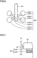
Fig. 6 is a perspective view of the microphone according to another example of the fourth modification; -
Fig. 7 is a partial cross-sectional view of a microphone according to one example of a fifth modification; -
Fig. 8 is a partial cross-sectional view of the microphone according to another example of the fifth modification; -
Fig. 9 is a partial cross-sectional view of a microphone according to one example of a sixth modification; -
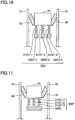
Fig. 10 is a partial cross-sectional view of a microphone according to another example of the sixth modification; and -
Fig. 11 is a partial cross-sectional view of a microphone according to yet another example of the sixth modification. - Hereinafter, there will be described one embodiment by reference to the drawings.
Fig. 1 is a partial cross-sectional view of amicrophone 1 according to one embodiment. The microphone 1 is a handheld microphone having a substantially cylindrical shape.Fig. 1 is a cross-sectional view of a head portion of themicrophone 1, taken along a plane including the central axis of the microphone 1 (i.e., the central axis of the cylindrical shape). As illustrated inFig. 1 , themicrophone 1 includes: ahousing 10; amicrophone unit 20; aninsulator 30 that supports themicrophone unit 20 with respect to thehousing 10; awindshield 40 that covers themicrophone unit 20; and a dynamic vibration absorber 50A mounted to themicrophone unit 20. - The
housing 10 is a cylindrical member formed of resin or metal. When using themicrophone 1, a user holds thehousing 10 such that thewindshield 40 faces vertically upward. Thewindshield 40 is configured to protect themicrophone unit 20 and formed of metal mesh, for example. Thewindshield 40 allows sounds having arrived from the outside to pass through thewindshield 40 to an inner space defined by thewindshield 40 and thehousing 10. As illustrated inFig. 1 , themicrophone unit 20 is supported by theinsulator 30 in this inner space. - The
microphone unit 20 is a substantially cylindrical member having a diameter that is less than that of thehousing 10. Themicrophone unit 20 includes: a diaphragm formed of synthetic resin or metal; and an electroacoustic transducer configured to convert vibrations of the diaphragm which are caused by sounds having arrived from the outside, to sound signals and output these sound signals.Fig. 1 omits illustration of the diaphragm and the electroacoustic transducer. The configuration of the electroacoustic transducer may be that of an electroacoustic transducer in conventional microphone units. Specifically, the electroacoustic transducer includes: a voice coil connected to the diaphragm; and magnets and a yoke which generate a magnetic field interlinked with the voice coil. - The
insulator 30 is a cylindrical member having an inverted conical trapezoid shape and formed of an elastic material such as fluororubber. Theinsulator 30 has opposite end faces orthogonal to the central axis of the insulator 30 (i.e., the rotation axis of the inverted conical trapezoid shape). In the following description, one of the end faces which has a radius less than that of the other of the end faces may be referred to as "first end face", and the other may be referred to as "second end face". - When using the
microphone 1 according to the present embodiment, the user holds thehousing 10 such that thewindshield 40 faces vertically upward. In this state, theinsulator 30 is mounted to thehousing 10 such that the first end face faces vertically downward (the direction indicated by arrow X inFig. 1 ), that is, theinsulator 30 is mounted to thehousing 10 such that the first end face that is one of the end faces of theinsulator 30 which has a radius less than that of the other is located below the second end face that is the other of the end faces of theinsulator 30 which has the radius greater than that of the one of the end faces. The inside diameter of the first end face of theinsulator 30 is substantially equal to the outside diameter of themicrophone unit 20. An inner circumferential portion of the first end face is in contact with themicrophone unit 20 to support themicrophone unit 20. The outside diameter of the second end face of theinsulator 30 is substantially equal to the inside diameter of thehousing 10. An outer circumferential portion of the second end face is in contact with thehousing 10. The outer circumferential portion of the second end face is in contact with an inner circumferential surface of thehousing 10 to support theinsulator 30 with respect to thehousing 10. - A
screw 210 extending vertically downward is provided on a bottom surface of themicrophone unit 20. Thedynamic vibration absorber 50A is mounted on thescrew 210. Thedynamic vibration absorber 50A includes anelastic member 510A andweight members 520A-1, 520A-2 mounted on theelastic member 510A. In thedynamic vibration absorber 50A, what is called a spring-mass system is formed by the elasticity of theelastic member 510A and the mass of theweight members 520A-1, 520A-2. In the present embodiment, a resonance of the spring-mass system reduces vibrations of themicrophone unit 20 vertically in the up and down direction. More specifically, when vibrations are transmitted from a hand of the user holding themicrophone 1 to thehousing 10, and vibrations vertically in the up and down direction are caused on themicrophone unit 20 supported in thehousing 10, theelastic member 510A (more precisely, acoupling member 514 which will be described below) vibrates, and theweight members 520A-1, 520A-2 vibrate at a phase reverse to that of themicrophone unit 20. The vibrations of theweight members 520A-1, 520A-2 at the reverse phase reduce vibrations of themicrophone unit 20. -
Fig. 2 is an exploded perspective view of thedynamic vibration absorber 50A. Theelastic member 510A is a flat disc-like member formed of a material having viscoelasticity such as fluororubber. It is noted that the material of theelastic member 510A is not limited to a material having viscoelasticity and at least needs to be a material having elasticity such as resin. Theelastic member 510A includes: a weight-member holder 512 shaped like a ring; and thecoupling member 514 shaped like a cross and provided on an inner circumferential side of the weight-member holder 512. Ahole 514a is formed in the center of thecoupling member 514. Thescrew 210 is to be inserted in thehole 514a. The weight-member holder 512 has fourholes 512a equally spaced apart from each other in the circumferential direction. In themicrophone 1 according to the present embodiment, as illustrated inFig. 1 , thescrew 210 is inserted in a nut 60-1, a washer 70-1, thehole 514a of thecoupling member 514, a washer 70-2, and a nut 60-2, and the nuts 60-1, 60-2 are tightened, whereby theelastic member 510A is mounted to themicrophone unit 20. That is, theelastic member 510A is mounted to themicrophone unit 20 at a portion of theelastic member 510A around thehole 514a. The portion of theelastic member 510A around thehole 514a is a portion of the disc-likeelastic member 510A near its center. For example, this portion is a portion of the disc-likeelastic member 510A sandwiched between the nuts 60-1, 60-2 and the washers 70-1, 70-2 vertically in the up and down direction (noted that this portion may be hereinafter referred to as "near-center portion"). Theweight members 520A-1, 520A-2 are held by the weight-member holder 512 located at a distance from the near-center portion. A portion (e.g., the coupling member 514) of theelastic member 510A between the near-center portion mounted to themicrophone unit 20 and the weight-member holder 512 holding theweight members 520A-1, 520A-2 is elastically deformed to vibrate theweight members 520A-1, 520A-2 and themicrophone unit 20 respectively in opposite phases. Since the center of an elastically deformable portion of theelastic member 510A is located at the same position as the center of the disc-likeelastic member 510A, a direction in which theweight members 520A-1, 520A-2 vibrate in the reverse phase coincides with the central axis of the microphone 1 (the central axis of the housing 10). This configuration reduces handling noise well. - The washer 70-1 and the washer 70-2 are annular members having the same size and formed of metal having difficulty in deformation, such as stainless steel, for example. In the following description, each of the washer 70-1 and the washer 70-2 may be referred to as "washer 70" in the case where there is no need of distinction between the washer 70-1 and the washer 70-2. As illustrated in
Fig. 1 , the width of an annular portion of the washer 70 (i.e., the length of the annular portion in the radial direction) is less than the length of thecoupling member 514 in the radial direction, and only a portion of thecoupling member 514 which is not located between the washer 70-1 and the washer 70-2 in thedynamic vibration absorber 50A serves as a spring of the spring-mass system. Since the washer 70 is formed of metal having difficulty in deformation as described above, shear deformation of a portion of thecoupling member 514 which is located between the washer 70-1 and the washer 70-2 is inhibited by the washer 70-1 and the washer 70-2. - In the case where the
elastic member 510A is mounted on thescrew 210 using a washer having a larger width at its annular portion instead of the washer 70, the spring constant in the spring-mass system is smaller than that in the present embodiment, and the resonant frequency of the dynamic vibration absorber 50Ais lower than that in the present embodiment. In contrast, in the case where theelastic member 510A is mounted on thescrew 210 using a washer having a smaller width at its annular portion instead of the washer 70, the spring constant in the spring-mass system is greater than that in the present embodiment, and the resonant frequency of thedynamic vibration absorber 50A is higher than that in the present embodiment. That is, the washer 70 in themicrophone 1 serves as an adjusting member that adjusts the elasticity of theelastic member 510A to adjust the resonant frequency of thedynamic vibration absorber 50A. In themicrophone 1 according to the present embodiment, since the resonant frequency of thedynamic vibration absorber 50A can be adjusted by selecting the washer 70, it is possible to finely deal with vibrations of themicrophone unit 20 in accordance with the frequency of handling noise to be reduced. - Each of the
weight members 520A-1, 520A-2 is a ring-like member formed of metal having high stiffness, such as aluminum. The reason why each of theweight members 520A-1, 520A-2 is formed of metal in the present embodiment is that each of theweight members 520A-1, 520A-2 needs to have some weight, and an occurrence of a resonance in the weight member itself is not preferable. However, each of theweight members 520A-1, 520A-2 may be formed of any material as long as each of theweight members 520A-1, 520A-2 has some weight, and a resonance in the weight member itself does not occur. - Four protruding portions 522 (see
Fig. 1 ) are provided on a bottom surface of theweight member 520A-1. The protrudingportions 522 correspond respectively to the fourholes 512a. A flat surface of theweight member 520A-2 has fourholes 524 corresponding respectively to the four protrudingportions 522. In the state in which theweight member 520A-1 is mounted on theelastic member 510A, a distal end of each of the protrudingportions 522 protrudes downward from a corresponding one of theholes 512a formed in theelastic member 510A. Theweight members 520A-1, 520A-2 are mounted on theelastic member 510A by fitting the protrudingportions 522 into therespective holes 524, with theelastic member 510A interposed between theweight members 520A-1, 520A-2. - The mass (the weight) of each of the
weight members 520A-1, 520A-2 is set such that the center of gravity of a system constituted by themicrophone unit 20, theelastic member 510A, and theweight members 520A-1, 520A-2 (noted that this center may be hereinafter referred to simply as "the center of gravity of the system") is located at a height position of the first end face of theinsulator 30 in the vertical direction. This configuration improves stability when theinsulator 30 supports the system constituted by themicrophone unit 20, theelastic member 510A, and theweight members 520A-1, 520A-2. As described above, theinsulator 30 supports themicrophone unit 20 by the first end face that is one of the end faces of theinsulator 30 which has a radius less than that of the other, at a position at which theinsulator 30 and themicrophone unit 20 are in contact with each other. Thus, it is possible for theinsulator 30 to stably support themicrophone unit 20 by making the center of gravity of the system in the vertical direction coincide with the position of the first end face of theinsulator 30 in the vertical direction. Accordingly, in the case where themicrophone unit 20, for example, is supported by theinsulator 30 at a first position which is located between the top face and the bottom face of themicrophone unit 20 in the vertical direction and at which theinsulator 30 and themicrophone unit 20 are in contact with each other, the masses of theweight members 520A-1, 520A-2 are preferably determined such that the center of gravity of the system substantially coincides with the first position in the vertical direction. -
Fig. 3 is a view for explaining the effects of the present embodiment.Fig. 3 illustrates graphs each representing a relationship between a vibration speed and a frequency of an evaluation surface for a corresponding one of themicrophone 1 according to the present embodiment and a microphone for comparison which is configured by removing thedynamic vibration absorber 50A from themicrophone 1, in the case where an upper surface SL of the microphone unit 20 (seeFig. 1 ) is set as the evaluation surface. The microphone for comparison is a conventional handheld microphone not including thedynamic vibration absorber 50A. - The vertical axis in
Fig. 3 is a coordinate axis representing a common logarithm value of the vibration speed of the evaluation surface in the case where the upper surface SL of the microphone unit 20 (seeFig. 1 ) is set as the evaluation surface. The horizontal axis inFig. 3 is a coordinate axis representing a common logarithm value of the frequency. The graph G01 inFig. 3 represents a relationship between the vibration speed and the frequency of the evaluation surface in themicrophone 1. The graph G02 inFig. 3 represents a relationship between the vibration speed and the frequency of the evaluation surface in the microphone for comparison. - As is obvious when the graph G01 and the graph G02 in
Fig. 3 are compared with each other, the vibration speed in a frequency range around 80 Hz is considerably less in themicrophone 1 according to the present embodiment than in the microphone for comparison. Thus, even in the case where the peak of the graph G02 in the frequency range around 80 Hz is a peak that cannot be sufficiently shifted to the lower limit in an audible frequency range in conventional techniques, themicrophone 1 according to the present embodiment can lower the peak to reduce handling noise corresponding to the peak. - Since the
microphone 1 according to the present embodiment can lower the resonance peak that cannot be sufficiently shifted to a frequency lower than the lower limit in the audible frequency range in the conventional techniques, there is no need for theinsulator 30 to hold themicrophone unit 20 by a smaller force in order to reduce handling noise. Accordingly, in themicrophone 1 according to the present embodiment, there is no need for theinsulator 30 to hold themicrophone unit 20 by a smaller force in order to reduce handling noise, thereby ensuring the quality of a product. - Thus, the
microphone 1 according to the present embodiment can ensure the quality of the product and reduce handling noise when compared with conventional microphones. - While the embodiment has been described above, it is to be understood that the disclosure is not limited to the details of the illustrated embodiment, but may be embodied with various changes and modifications, which may occur to those skilled in the art, within the scope defined by the appended claims.
- While the
microphone 1 according to the above-described embodiment includes the washer 70 as the adjusting member that adjusts the elasticity of theelastic member 510A, the adjusting member may be omitted. That is, the microphone according to the present disclosure at least needs to include: a housing; a microphone unit provided in the housing; an elastic member mounted to the microphone unit; and a weight member mounted to the elastic member. While theelastic member 510A is mounted to themicrophone unit 20 with thescrew 210 in the above-described embodiment, an extending portion (including thescrew 210 in one embodiment) extending from the bottom surface of themicrophone unit 20 may be secured to theelastic member 510A with, e.g., adhesive to mount theelastic member 510A to themicrophone unit 20. In the case where theelastic member 510A is mounted in this manner, it is preferable that the extending portion is secured to the portion of the disc-likeelastic member 510A near its center (the near-center portion), and a portion of theelastic member 510A which is located at a distance from the near-center portion is formed as the weight-member holder 512. With this configuration, the portion of theelastic member 510A which is located between the weight-member holder 512 and the near-center portion of theelastic member 510A is elastically deformable, making it possible to reduce handling noise. As long as handling noise is reduced, the weight-member holder 512 may have any shape other than the ring-shape. Likewise, as long as handling noise is reduced, each of theweight members 520A-1, 520A-2 may have any shape other than the ring-shape. Thecoupling member 514 may have any shape other than the cross-shape. - In the
microphone 1 according to the above-described embodiment, the mass (the weight) of each of theweight members 520A-1, 520A-2 is set such that the center of gravity of the system constituted by themicrophone unit 20, theelastic member 510A, and theweight members 520A-1, 520A-2 is located at the position on the first end face of the insulator 30 (i.e., a position of the point of action of a force for supporting the system in the vertical direction). However, the mass of each of theweight members 520A-1, 520A-2 may be set in accordance with a relationship with the resonance peak to be reduced, independently of the position of the center of gravity. In a modification in which the adjusting member is omitted like the first modification, the resonant frequency of thedynamic vibration absorber 50A is determined in accordance with the mass of each of theweight members 520A-1, 520A-2. Accordingly, in the modification in which the adjusting member is omitted, the mass of each of theweight members 520A-1, 520A-2 at least needs to be determined independently of the position of the center of gravity, such that the frequency at the resonance peak to be lowered and the resonant frequency of thedynamic vibration absorber 50A coincide with each other. - The
dynamic vibration absorber 50A in the above-described embodiment includes: theelastic member 510A mounted on thescrew 210 extending downward from the bottom surface of themicrophone unit 20; and theweight members 520A-1, 520A-2 mounted on theelastic member 510A so as to hold theelastic member 510A between theweight members 520A-1, 520A-2. In a third modification, as illustrated inFig. 4 , thedynamic vibration absorber 50A is replaced with adynamic vibration absorber 50B that includes:elastic members 510A-1, 510A-2 mounted on thescrew 210; and aweight member 520B held by and between theelastic members 510A-1, 510A-2. It is noted thatFig. 4 omits illustration of nuts for securing the elastic member to thescrew 210 and illustration of a windshield (noted that these illustrations are omitted also inFig. 5 ). Though not illustrated inFig. 4 in detail, theweight member 520B is a ring-like member formed of, e.g., metal like theweight member 520A-1 in the above-described embodiment. Theweight member 520B is different from theweight member 520A-1 in that the protrudingportions 522 are provided on both of an upper surface and a bottom surface of theweight member 520B. - The
elastic member 510A of thedynamic vibration absorber 50A in the above-described embodiment is shaped like a disc having a diameter that is less than the inside diameter of thehousing 10. As illustrated inFig. 5 , however, a microphone according to a modification may include adynamic vibration absorber 50C including anelastic member 510B instead of theelastic member 510A. Theelastic member 510B is shaped like a disc having a diameter that is substantially equal to the inside diameter of thehousing 10. Thus, in the microphone using thedynamic vibration absorber 50C, the outer periphery of theelastic member 510B is in contact with the inner circumferential surface of thehousing 10 as one example of an inner wall. This configuration reduces rotational vibrations of themicrophone unit 20 in a circumferential direction centered about the axis of thehousing 10, thereby reducing handling noise caused by the rotational vibrations. As illustrated inFig. 6 , thedynamic vibration absorber 50C may be replaced with adynamic vibration absorber 50C' including:elastic members 510B'-1, 510B'-2, 510B'-3, 510B'-4 each shaped like a rod and each extending in a direction intersecting thescrew 210 and secured at its one end to thescrew 210; andweight members 520B'-1, 520B'-2, 520B'-3, 520B'-4 mounted respectively on the other ends of the respectiveelastic members 510B'-1, 510B'-2, 510B'-3, 510B'-4. This configuration achieves the same effects as achieved by thedynamic vibration absorber 50C, by adjusting the lengths of the respectiveelastic members 510B'-1, 510B'-2, 510B'-3, 510B'-4 such that theweight members 520B'-1, 520B'-2, 520B'-3, 520B'-4 are in contact with the inner circumferential surface of thehousing 10. - In the
microphone 1 according to the above-described embodiment, thedynamic vibration absorber 50A is mounted on thescrew 210 extending from the bottom surface of themicrophone unit 20. As illustrated inFig. 7 , however, a microphone according to a modification may include adynamic vibration absorber 50D including: anelastic member 510C shaped like a disc and mounted at one (as one example of a first surface) of its opposite surfaces on the bottom surface of themicrophone unit 20; and aweight member 520C mounted on the other surface (as one example of a second surface) of theelastic member 510C. As illustrated inFig. 8 , a microphone according to a modification may include adynamic vibration absorber 50D' including: anelastic member 510C' formed of resin or metal and shaped like a spiral spring mounted at its one end (as one example of a first end) on the bottom surface of themicrophone unit 20; and theweight member 520C mounted on the other end (as one example of a second end) of theelastic member 510C'. It is noted that an adhesive may be used for mounting of theelastic member 510C (or theelastic member 510C') on themicrophone unit 20 and mounting of theweight member 520C on theelastic member 510C (or theelastic member 510C'), for example. - The
microphone 1 according to the above-described embodiment includes only one pair of the elastic member mounted to the microphone unit and the weight member mounted on the elastic member. However, a microphone according to a modification may include at least one elastic member mounted to the microphone unit and at least one weight member mounted on the at least one elastic member. For example, the microphone may include a plurality of pairs of the elastic members and the weight members. Such a microphone can deal with a plurality of frequencies of handling noise. For example, in the case where N pairs of the elastic members and the weight members are provided, it is possible to reduce handling noise of up to N + 1 types. - For example,
Fig. 9 illustrates a microphone including adynamic vibration absorber 50E that includes: anelastic member 510C-1 shaped like a disc and mounted at one of its opposite surfaces on the bottom surface of themicrophone unit 20; aweight member 520C-1 having a mass m1 and mounted on the other surface of theelastic member 510C-1; anelastic member 510C-2 shaped like a disc and mounted at one of its opposite surfaces on theweight member 520C-1; and aweight member 520C-2 having a mass m2 and mounted on the other surface of theelastic member 510C-2. The mass m2 is not equal to the mass m1. This microphone can lower the resonance peak of the frequency related to the mass m1, the resonance peak of the frequency related to the mass m2, and the resonance peak of the frequency related to the sum of the mass m1 and the mass m2. - As illustrated in
Fig. 10 , thedynamic vibration absorber 50E may be replaced with adynamic vibration absorber 50E' including: anelastic member 510C'-1, anelastic member 510C'-2, and anelastic member 510C'-3 each formed of resin or metal and each shaped like a spiral spring mounted at its one end on the bottom surface of themicrophone unit 20; aweight member 520C-1 mounted on the other end of theelastic member 510C'-1; aweight member 520C-2 mounted on the other end of theelastic member 510C'-2; and aweight member 520C-3 mounted on the other end of theelastic member 510C'-3. As illustrated inFig. 11 , thedynamic vibration absorber 50E may be replaced with adynamic vibration absorber 50E" including: theelastic member 510C'-1, theelastic member 510C'-2, and theelastic member 510C'-3 each mounted at one end on themicrophone unit 20; and theweight member 520C mounted on the other ends of the respectiveelastic member 510C'-1, 510C'-2, 510C'-3.
Claims (15)
- A microphone (1) comprising:a housing (10);a microphone unit (20) that outputs a sound signal disposed in the housing (10);an elastic member (510A; 510A-1, 510A-2; 510B; 510B'-1, 510B'-2, 510B'-3, 510B'-4; 510C; 510C'; 510C-1, 510C-2; 510C'-1, 510C'-2, 510C'-3) mounted to the microphone unit (20); anda weight member (520A-1, 520A-2; 520B; 520A-1, 520A-2; 520B'-1, 520B'-2, 520B'-3, 520B'-4; 520C; 520C-1, 520C-2; 520C-1, 520C-2, 520C-3; 520C) mounted to the elastic member (510A; 510A-1, 510A-2; 510B; 510B'-1, 510B'-2, 510B'-3, 510B'-4; 510C; 510C'; 510C-1, 510C-2; 510C'-1, 510C'-2, 510C'-3).
- The microphone (1) according to claim 1, further comprising an insulator (30) supporting the microphone unit (20) with respect to the housing (10) and in contact with the housing (10) at a predetermined position in a vertical direction,
wherein a weight of the weight member (520A-1, 520A-2; 520B; 520A-1, 520A-2; 520B'-1, 520B'-2, 520B'-3, 520B'-4; 520C; 520C-1, 520C-2; 520C-1, 520C-2, 520C-3; 520C) is determined to allow a center of gravity of a system constituted by the microphone unit (20), the elastic member (510A; 510A-1, 510A-2; 510B; 510B'-1, 510B'-2, 510B'-3, 510B'-4; 510C; 510C'; 510C-1, 510C-2; 510C'-1, 510C'-2, 510C'-3), and the weight member (520A-1, 520A-2; 520B; 520A-1, 520A-2; 520B'-1, 520B'-2, 520B'-3, 520B'-4; 520C; 520C-1, 520C-2; 520C-1, 520C-2, 520C-3; 520C) to be located at the predetermined position. - The microphone (1) according to claim 1 or 2, further comprising an adjusting member (70) configured to adjust elasticity of the elastic member (510A).
- The microphone (1) according to any one of claims 1 through 3, further comprising a plurality of pairs of ones of the elastic member (510C-1, 510C-2; 510C'-1, 510C'-2, 510C'-3) and a plurality of ones of the weight member (520C-1, 520C-2; 520C-1, 520C-2, 520C-3).
- The microphone (1) according to any one of claims 1 through 3, wherein the elastic member (510A; 510A-1, 510A-2; 510B; 510C; 510C-1, 510C-2):has a disc shape,is mounted to the microphone unit (20) at a portion of the elastic member (510A; 510A-1, 510A-2; 510B; 510C; 510C-1, 510C-2) located in a vicinity of a center of the disc shape of the elastic member (510A; 510A-1, 510A-2; 510B; 510C; 510C-1, 510C-2), andholds the weight member (520A-1, 520A-2; 520B; 520A-1, 520A-2; 520C; 520C-1, 520C-2) at a distance from the portion of the elastic member (510A; 510A-1, 510A-2; 510B; 510C; 510C-1, 510C-2) located in the vicinity of the center.
- The microphone (1) according to claim 5, further comprising:an extending member (210) extending from a bottom surface of the microphone unit (20),wherein the portion of the elastic member (510A; 510A-1, 510A-2; 510B) located in the vicinity of the center is secured to the extending member (210) to mount the elastic member (510A; 510A-1, 510A-2; 510B) to the microphone unit (20).
- The microphone (1) according to claim 6, wherein the portion of the elastic member (510A; 510A-1, 510A-2; 510B) located in the vicinity of the center includes a hole (514a) through which the extending member (210) extends.
- The microphone (1) according to claim 7, wherein the extending member (210) is a screw (210), and
the portion of the elastic member (510A; 510A-1, 510A-2; 510B) located in the vicinity of the center is held between a pair of nuts (60-1, 60-2) secured to the screw (210) and between a pair of washers (70-1, 70-2) inserted in the screw (210), with the screw (210) inserted in the hole (514a), to mount the elastic member (510A; 510A-1, 510A-2; 510B) to the microphone unit (20). - The microphone (1) according to any one of claims 5 through 8, wherein the weight member (520A-1, 520A-2; 520B; 520A-1, 520A-2; 520C; 520C-1, 520C-2) has a ring shape disposed at a distance from the portion of the elastic member (510A; 510A-1, 510A-2; 510B; 510C; 510C-1, 510C-2) located in the vicinity of the center.
- The microphone (1) according to claim 5 or 6, wherein:the weight member (520A-1, 520A-2; 520B; 520A-1, 520A-2; 520C; 520C-1, 520C-2) has a ring shape, andthe elastic member (510A; 510A-1, 510A-2; 510B; 510C; 510C-1, 510C-2) includes:a weight-member holder (512) having a ring shape configured to hold the weight member (520A-1, 520A-2; 520B; 520A-1, 520A-2; 520C; 520C-1, 520C-2); anda coupling member (514) having a cross shape and provided on an inner circumferential side of the weight-member holder (512).
- The microphone (1) according to claim 10, further comprising:an extending member (210) extending from a bottom surface of the microphone unit (20),wherein the coupling member (514) at a center thereof includes a hole (514a) through which the extending member (210) is inserted.
- The microphone (1) according to claim 11, wherein:the extending member (210) is a screw (210), anda portion of the coupling member (514) of the elastic member (510A; 510A-1, 510A-2; 510B) located in the vicinity of the center is held between a pair of nuts (60-1, 60-2) secured to the screw (210) and between a pair of washers (70-1, 70-2) inserted in the screw (210), with the screw (210) inserted in the hole (514a), to mount the elastic member (510A; 510A-1, 510A-2; 510B) to the microphone unit (20).
- The microphone (1) according to any one of claims 1 through 4, wherein one of the elastic member (510B; 510B'-1, 510B'-2, 510B'-3, 510B'-4) or the weight member (520A-1, 520A-2; 520B'-1, 520B'-2, 520B'-3, 520B'-4) is in contact with an inner wall of the housing (10).
- The microphone (1) according to any one of claims 1 through 4, wherein:the elastic member (510C; 510C-1, 510C-2) has a disc shape, anda first surface of the elastic member (510C; 510C-1, 510C-2) is mounted on a bottom surface of the microphone unit (20), and the weight member (520C; 520C-1, 520C-2) is mounted on a second surface of the elastic member (510C; 510C-1, 510C-2).
- The microphone (1) according to any one of claims 1 through 4, wherein:the elastic member (510C'; 510C'-1, 510C'-2, 510C'-3) is a coil spring (510C'; 510C'-1, 510C'-2, 510C'-3), anda first end of the coil spring (510C'; 510C'-1, 510C'-2, 510C'-3) is attached to a bottom surface of the microphone unit (20), and a second end of the coil spring (510C'; 510C'-1, 510C'-2, 510C'-3) is attached to the weight member (520C; 520C-1, 520C-2, 520C-3; 520C).
Applications Claiming Priority (1)
| Application Number | Priority Date | Filing Date | Title |
|---|---|---|---|
| JP2018205398A JP2020072386A (en) | 2018-10-31 | 2018-10-31 | Microphone |
Publications (1)
| Publication Number | Publication Date |
|---|---|
| EP3648469A1 true EP3648469A1 (en) | 2020-05-06 |
Family
ID=68392742
Family Applications (1)
| Application Number | Title | Priority Date | Filing Date |
|---|---|---|---|
| EP19205890.7A Withdrawn EP3648469A1 (en) | 2018-10-31 | 2019-10-29 | Microphone |
Country Status (4)
| Country | Link |
|---|---|
| US (1) | US20200137473A1 (en) |
| EP (1) | EP3648469A1 (en) |
| JP (1) | JP2020072386A (en) |
| CN (1) | CN111131983A (en) |
Families Citing this family (4)
| Publication number | Priority date | Publication date | Assignee | Title |
|---|---|---|---|---|
| EP4035416B1 (en) * | 2020-01-17 | 2024-10-16 | Shenzhen Shokz Co., Ltd. | Microphone and electronic device having the same |
| CN111556404B (en) * | 2020-05-29 | 2025-10-14 | 安克创新科技股份有限公司 | A speaker |
| CN114026879A (en) * | 2020-10-20 | 2022-02-08 | 深圳市大疆创新科技有限公司 | Sound transmission assembly, microphone, wind shield, sound transmission device, and sound transmission method |
| EP4054206B1 (en) | 2021-03-01 | 2023-09-13 | Infineon Technologies AG | Mems device with a tuned mass damping structure |
Citations (5)
| Publication number | Priority date | Publication date | Assignee | Title |
|---|---|---|---|---|
| JPS5256726U (en) * | 1975-10-22 | 1977-04-23 | Panasonic Corp | |
| JPS6165600A (en) * | 1984-09-05 | 1986-04-04 | Sawafuji Dainameka Kk | Piezo-electric oscillator |
| JP2007285377A (en) * | 2006-04-14 | 2007-11-01 | Aisin Seiki Co Ltd | Vibration damping device |
| US20120002832A1 (en) * | 2010-06-30 | 2012-01-05 | Kabushiki Kaisha Audio-Technica | Dynamic microphone |
| US20120140972A1 (en) * | 2010-12-02 | 2012-06-07 | Hiroshi Akino | Dynamic Microphone |
Family Cites Families (4)
| Publication number | Priority date | Publication date | Assignee | Title |
|---|---|---|---|---|
| JP2005354581A (en) * | 2004-06-14 | 2005-12-22 | Nikon Corp | Electronics and camera |
| JP4685654B2 (en) * | 2006-02-09 | 2011-05-18 | パナソニック株式会社 | Microphone device |
| CN202696881U (en) * | 2012-07-13 | 2013-01-23 | 北京龙峰经典科技有限公司 | Condenser microphone |
| CN206235391U (en) * | 2016-11-18 | 2017-06-09 | 甘肃蓝博检测科技有限公司 | A kind of portable environmental noise detector |
-
2018
- 2018-10-31 JP JP2018205398A patent/JP2020072386A/en active Pending
-
2019
- 2019-10-14 CN CN201910971917.9A patent/CN111131983A/en active Pending
- 2019-10-28 US US16/665,380 patent/US20200137473A1/en not_active Abandoned
- 2019-10-29 EP EP19205890.7A patent/EP3648469A1/en not_active Withdrawn
Patent Citations (6)
| Publication number | Priority date | Publication date | Assignee | Title |
|---|---|---|---|---|
| JPS5256726U (en) * | 1975-10-22 | 1977-04-23 | Panasonic Corp | |
| JPS6165600A (en) * | 1984-09-05 | 1986-04-04 | Sawafuji Dainameka Kk | Piezo-electric oscillator |
| JP2007285377A (en) * | 2006-04-14 | 2007-11-01 | Aisin Seiki Co Ltd | Vibration damping device |
| US20120002832A1 (en) * | 2010-06-30 | 2012-01-05 | Kabushiki Kaisha Audio-Technica | Dynamic microphone |
| JP5595143B2 (en) | 2010-06-30 | 2014-09-24 | 株式会社オーディオテクニカ | Dynamic microphone |
| US20120140972A1 (en) * | 2010-12-02 | 2012-06-07 | Hiroshi Akino | Dynamic Microphone |
Also Published As
| Publication number | Publication date |
|---|---|
| JP2020072386A (en) | 2020-05-07 |
| CN111131983A (en) | 2020-05-08 |
| US20200137473A1 (en) | 2020-04-30 |
Similar Documents
| Publication | Publication Date | Title |
|---|---|---|
| US20200137473A1 (en) | Microphone | |
| US7791456B2 (en) | Vibrator | |
| US3786202A (en) | Acoustic transducer including piezoelectric driving element | |
| EP1261232A1 (en) | Bone conduction speaker | |
| US20050276434A1 (en) | Dynamic exciter and loudspeaker using the same | |
| JP3192100B2 (en) | Microphone | |
| US8467558B2 (en) | Dynamic microphone | |
| CN116582808B (en) | Megaphone | |
| CN101606396A (en) | Vibrating membrane of electronic sounder and electronic sounder having the same | |
| EP4236369A2 (en) | Modal frequency shifting for loudspeaker devices | |
| US4199667A (en) | Microphone having means for suppressing structure-borne sounds | |
| WO2001056329A2 (en) | Electroacoustic transducer having a moving coil and having elastic holding elements for the connecting leads of the moving coil | |
| CN108696804B (en) | Loudspeaker with vibration control system | |
| CN110710228B (en) | Speaker structure | |
| CN109218935B (en) | Rectangular round corner centering support piece and loudspeaker | |
| KR101500308B1 (en) | Bone conduction output apparatus | |
| JP4598087B2 (en) | Speaker device | |
| JP2019042661A (en) | Vibrator unit | |
| JP2000314628A (en) | Vibration-proof device of angular velocity sensor and angular velocity sensor device | |
| JPS5868396A (en) | Elastic support for electroacoustic converter | |
| JP2023136905A (en) | Sound generation device | |
| KR102699321B1 (en) | Actuator for generating sound and vibration | |
| JP2012175240A (en) | Electrodynamic exciter | |
| JP6533120B2 (en) | Dynamic microphone | |
| RU2785574C1 (en) | Vibrating device |
Legal Events
| Date | Code | Title | Description |
|---|---|---|---|
| PUAI | Public reference made under article 153(3) epc to a published international application that has entered the european phase |
Free format text: ORIGINAL CODE: 0009012 |
|
| STAA | Information on the status of an ep patent application or granted ep patent |
Free format text: STATUS: THE APPLICATION HAS BEEN PUBLISHED |
|
| AK | Designated contracting states |
Kind code of ref document: A1 Designated state(s): AL AT BE BG CH CY CZ DE DK EE ES FI FR GB GR HR HU IE IS IT LI LT LU LV MC MK MT NL NO PL PT RO RS SE SI SK SM TR |
|
| AX | Request for extension of the european patent |
Extension state: BA ME |
|
| 18D | Application deemed to be withdrawn |
Effective date: 20201107 |