EP3648347A1 - In-phase suppression circuit - Google Patents
In-phase suppression circuit Download PDFInfo
- Publication number
- EP3648347A1 EP3648347A1 EP17919228.1A EP17919228A EP3648347A1 EP 3648347 A1 EP3648347 A1 EP 3648347A1 EP 17919228 A EP17919228 A EP 17919228A EP 3648347 A1 EP3648347 A1 EP 3648347A1
- Authority
- EP
- European Patent Office
- Prior art keywords
- line
- signal
- coupled
- phase
- output terminal
- Prior art date
- Legal status (The legal status is an assumption and is not a legal conclusion. Google has not performed a legal analysis and makes no representation as to the accuracy of the status listed.)
- Withdrawn
Links
Images


Classifications
-
- H—ELECTRICITY
- H01—ELECTRIC ELEMENTS
- H01P—WAVEGUIDES; RESONATORS, LINES, OR OTHER DEVICES OF THE WAVEGUIDE TYPE
- H01P1/00—Auxiliary devices
- H01P1/22—Attenuating devices
- H01P1/222—Waveguide attenuators
-
- H—ELECTRICITY
- H01—ELECTRIC ELEMENTS
- H01P—WAVEGUIDES; RESONATORS, LINES, OR OTHER DEVICES OF THE WAVEGUIDE TYPE
- H01P1/00—Auxiliary devices
- H01P1/22—Attenuating devices
- H01P1/227—Strip line attenuators
-
- H—ELECTRICITY
- H01—ELECTRIC ELEMENTS
- H01P—WAVEGUIDES; RESONATORS, LINES, OR OTHER DEVICES OF THE WAVEGUIDE TYPE
- H01P5/00—Coupling devices of the waveguide type
- H01P5/08—Coupling devices of the waveguide type for linking dissimilar lines or devices
- H01P5/10—Coupling devices of the waveguide type for linking dissimilar lines or devices for coupling balanced lines or devices with unbalanced lines or devices
-
- H—ELECTRICITY
- H03—ELECTRONIC CIRCUITRY
- H03H—IMPEDANCE NETWORKS, e.g. RESONANT CIRCUITS; RESONATORS
- H03H7/00—Multiple-port networks comprising only passive electrical elements as network components
- H03H7/42—Networks for transforming balanced signals into unbalanced signals and vice versa, e.g. baluns
-
- H—ELECTRICITY
- H03—ELECTRONIC CIRCUITRY
- H03H—IMPEDANCE NETWORKS, e.g. RESONANT CIRCUITS; RESONATORS
- H03H7/00—Multiple-port networks comprising only passive electrical elements as network components
- H03H7/42—Networks for transforming balanced signals into unbalanced signals and vice versa, e.g. baluns
- H03H7/425—Balance-balance networks
Definitions
- the present invention relates to an in-phase suppression circuit including a plurality of lines having a length of a quarter wavelength at a frequency of an input signal.
- the transmission scheme using a differential signal is to transmit signals the same in amplitude as each other but phases thereof are different from each other and shifted by 180 degrees on two signal lines, and is capable of superimposing information on a difference in the potential between the signals on the two signal lines.
- a device on the receiving side of the differential signal acquires the information by detecting the difference in the potential between the signals on the two signal lines.
- the two signals constituting the differential signal ideally have the same amplitude but reversed phases.
- an in-phase component which is called a common mode, an amplitude difference and a phase difference may be generated.
- Each of the amplitude difference and the phase difference between the two signals constituting the differential signal causes the balance of the differential signal to be lost, thereby contributing to unnecessary oscillation, a spurious, or non-linearity.
- balun which performs conversion between a balanced signal an unbalanced signal since it is necessary to suppress signal distortion caused by the differential amplifier or noise generated from the differential amplifier.
- Non-Patent Literature 1 discloses an in-phase suppression circuit including a first Marchand balun and a second Marchand balun as baluns for converting between a balanced signal and an unbalanced signal.
- the first Marchand balun includes first to fourth transmission lines having a length of a quarter wavelength at a frequency of an input signal.
- the second Marchand balun includes fifth to eighth transmission lines having a length of a quarter wavelength at a frequency of an input signal.
- In-phase signals input from the first signal input terminal and the second signal input terminal are canceled out, and thus are not output from the first signal output terminal and the second signal output terminal.
- Non-Patent Literature 1 K.S. Ang and I. D. Rebertson, "Analysis and Design of Impedance-Transforming Planar Marchand Baluns," IEEE Trans. On Microwave Theory and Techniques, vol. 49, no. 2, pp. 402-406, Feb. 2001 .
- the conventional in-phase suppression circuit is configured as described above, it is possible to suppress output of in-phase signals from the first signal output terminal and the second signal output terminal.
- the present invention has been made to solve the above disadvantage, and it is an object of the present invention to obtain an in-phase suppression circuit capable of reducing the number of transmission lines compared to the case of using two Marchand baluns that are independent of each other.
- An in-phase suppression circuit includes: a first line in which one end thereof is coupled to a first signal input terminal; a second line in which one end thereof is grounded and the other end thereof is coupled to a first signal output terminal, the second line being electromagnetically coupled to the first line; a third line in which one end thereof is open, the third line being electromagnetically coupled to the second line; a fourth line in which one end thereof is coupled to the other end of the first line and the other end is open; a fifth line in which one end thereof is coupled to a second signal output terminal and the other end thereof is grounded, the fifth line being electromagnetically coupled to the fourth line; and a sixth line in which one end thereof is coupled to the other end of the third line and the other end thereof is coupled to a second signal input terminal, the sixth line being electromagnetically coupled to the fifth line, wherein the first to sixth lines have a length of a quarter wavelength at a frequency of signals input from the first and second signal input terminals.
- the in-phase suppression circuit includes: a first line in which one end thereof is coupled to a first signal input terminal; a second line in which one end thereof is grounded and the other end thereof is coupled to a first signal output terminal, the second line being electromagnetically coupled to the first line; a third line in which one end thereof is open, the third line being electromagnetically coupled to the second line; a fourth line in which one end thereof is coupled to the other end of the first line and the other end is open; a fifth line in which one end thereof is coupled to a second signal output terminal and the other end thereof is grounded, the fifth line being electromagnetically coupled to the fourth line; and a sixth line in which one end thereof is coupled to the other end of the third line and the other end is coupled to a second signal input terminal, the sixth line being electromagnetically coupled to the fifth line. Therefore, there is an effect of reducing the number of transmission lines as compared with the case of using two Marchand balun independent of each other.
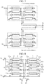
- FIG. 1 is a configuration diagram illustrating an in-phase suppression circuit according to a first embodiment of the present invention.
- a first signal input terminal 1a is a terminal for inputting a signal DS 1 in a microwave band or a millimeter wave band, for example.
- a second signal input terminal 1b is a terminal for inputting a signal DS 2 of a microwave band or a millimeter wave band, for example.
- the signal DS 1 and the signal DS 2 are the same in frequency as each other, and the phase of the signal DS 1 is 180 degrees different from the phase of the signal DS 2 .
- the signal DS 1 and the signal DS 2 constitute a differential signal.
- the phase of the signal DS 1 is 0 degrees and that the phase of the signal DS 2 is 180 degrees.
- the first coupled lines 2 include a first line 11, a second line 12, and a third line 13.
- Each of the first line 11, the second line 12, and the third line 13 has a length of a quarter wavelength at the center frequency of the signal DS 1 and the signal DS 2 .
- the first line 11 is a transmission line having one end 11a coupled to the first signal input terminal 1a.
- the second line 12 is a transmission line having one end 12a grounded and the other end 12b coupled to a first signal output terminal 4a, and is electromagnetically coupled to the first line 11.
- the third line 13 is a transmission line that is open at one end 13a and electromagnetically coupled to the second line 12.
- the second coupled lines 3 include a fourth line 21, a fifth line 22, and a sixth line 23.
- Each of the fourth line 21, the fifth line 22, and the sixth line 23 has a length of a quarter wavelength at the center frequency of the signal DS 1 and the signal DS 2 .
- the fourth line 21 is a transmission line having one end 21a coupled to the other end 11b of the first line 11 and the other end 21b open.
- the fifth line 22 is a transmission line in which one end 22a is coupled to a second signal output terminal 4b and the other end 22b is grounded, and is electromagnetically coupled to the fourth line 21.
- the sixth line 23 is a transmission line having one end 23a coupled to the other end 13b of the third line 13 and the other end 23b coupled to the second signal input terminal 1b, and is electromagnetically coupled to the fifth line 22.
- the first signal output terminal 4a outputs a signal DS 3 output from the first coupled lines 2.
- the second signal output terminal 4b outputs a signal DS 4 output from the second coupled lines 3.
- the first line 11 and the second line 12 included in the first coupled lines 2, and the fourth line 21 and the fifth line 22 included in the second coupled lines 3 form a first Marchand balun.
- the passing phase of the first Marchand balun is ⁇ .
- the second line 12 and the third line 13 included in the first coupled lines 2, and the fifth line 22 and the sixth line 23 included in the second coupled lines 3 form a second Marchand balun.
- the passing phase of the second Marchand balun is ⁇ .
- the second line 12 coupled to the first signal output terminal 4a is shared by the first Marchand balun and the second Marchand balun.
- the fifth line 22 coupled to the second signal output terminal 4b is shared by the first Marchand balun and the second Marchand balun.
- a signal DS 1-2 having a phase of (180 + ⁇ ) degrees appears at one end 22a of the fifth line 22.
- the signal DS 1-1 and the signal DS 2-2 appearing at the other end 12b of the second line 12 are in-phase combined since they both have the phase of (0 + ⁇ ) degrees.
- the signal DS 3 having the phase of (0 + ⁇ ) degrees is output from the first signal output terminal 4a as a composite signal of the signals DS 1-1 and DS 2-2 .
- the signal DS 1-2 and the signal DS 2-1 appearing at the one end 22a of the fifth line 22 are also in-phase combined since they both have the phase of (180 + ⁇ ) degrees.
- the signal DS 4 having the phase of (180 + ⁇ ) degrees is output from the second signal output terminal 4b as a composite signal of the signals DS 1-2 and DS 2-1 .
- the signal DS 3 and the signal DS 4 are differential signals.
- phase of the in-phase signal C is ⁇ .
- a signal C 1-2 having a phase of (180 + ⁇ + ⁇ ) degrees also appears at the one end 22a of the fifth line 22.
- a signal C 2-2 having a phase of (180 + ⁇ + ⁇ ) also appears at the other end 12b of the second line 12.
- balanced signal terminals of an ideal balun capable of generating differential signals are coupled to the first signal output terminal 4a and the second signal output terminal 4b.
- an unbalanced signal is input to the port (1).
- FIG. 2 is an explanatory graph illustrating the amplitude of the S parameter S21 and the amplitude of the S parameter S31 when differential signals are input.
- FIG. 3 is an explanatory graph illustrating a phase difference between the S parameter S21 and the S parameter S31 when differential signals are input.
- the lengths of the first line 11, the second line 12, the third line 13, the fourth line 21, the fifth line 22, and the sixth line 23 are each set to a quarter wavelength at 20 GHz.
- a passage loss in the in-phase suppression circuit is about -3 dB around a frequency of 20 GHz and that the differential signal is transmitted with almost no loss.
- a phase difference between the S parameter S21 and the S parameter S31 is 180 degrees at the frequency of 20 GHz and that transmission as differential signals is carried out.
- FIG. 4 is an explanatory graph illustrating the amplitude of the S parameter S54 and the amplitude of the S parameter S64 when in-phase signals are input.
- in-phase signals are attenuated by about 20 dB at the frequency of 20 GHz.
- the first line 11 having one end 11a coupled to the first signal input terminal 1a; the second line 12 having one end 12a grounded and the other end 12b coupled to the first signal output terminal 4a, the second line 12 electromagnetically coupled to the first line 11; the third line 13 having one end 13a open, the third line 13 electromagnetically coupled to the second line 12; the fourth line 21 having one end 21a coupled to the other end 11b of the first line 11 and the other end 21b open; a fifth line 22 having one end 22a coupled to the second signal output terminal 4b and the other end 22b grounded, the fifth line 22 electromagnetically coupled to the fourth line 21; and the sixth line 23 having one end 23a coupled to the other end 13b of the third line 13 and the other end 23b coupled to the second signal input terminal 1b, the sixth line 23 electromagnetically coupled to the fifth line 22.
- first line 11, the second line 12, the third line 13, the fourth line 21, the fifth line 22, and the sixth line 23 have a length of a quarter wavelength at a frequency of signals input from the first signal input terminal 1a and the second signal input terminal 1b.
- the in-phase suppression circuit disclosed in Non-Patent Literature 1 includes eight transmission lines, whereas in the first embodiment, the number of transmission lines included in the in-phase suppression circuit is six. The number of transmission lines has decreased by two.
- the first line 11, the second line 12, the third line 13, the fourth line 21, the fifth line 22, the sixth line 23 are arranged on a plane of a dielectric substrate including an integrated circuit (IC).
- IC integrated circuit
- first line 11, the second line 12, the third line 13, the fourth line 21, the fifth line 22, and the sixth line 23 is not limited to the arrangement on the plane of a dielectric substrate.
- the first line 11, the second line 12, the third line 13, the fourth line 21, the fifth line 22, and the sixth line 23 may be distributed to a plurality of layers, and lines arranged in different layers may be electromagnetically coupled to.
- the first Marchand balun includes the first to fourth transmission lines
- the second Marchand balun includes the fifth to eighth transmission lines.
- adding one transmission line to each of the coupled lines in the first and second Marchand baluns makes it possible to configure the first and second Marchand baluns even in a case where the amount of coupling between adjacent lines is reduced.
- first and second Marchand baluns can be configured even in a case where the amount of coupling between adjacent lines is reduced, the distance between the lines can be increased, thereby facilitating manufacturing.
- FIG. 5 is a configuration diagram illustrating a conventional in-phase suppression circuit including a first Marchand balun including first to sixth transmission lines and a second Marchand balun including seventh to twelfth transmission lines.
- the first to twelfth transmission lines have a length of a quarter wavelength at the frequency of input differential signals.
- FIG. 6 is a configuration diagram illustrating an in-phase suppression circuit according to a second embodiment of the present invention.
- the same symbol as that in FIG. 1 represents the same or a corresponding part and thus descriptions thereof are omitted.
- a seventh line 31 is a transmission line having one end 31a grounded and the other end 31b coupled to the first signal output terminal 4a.
- the seventh line 31 is arranged between the second line 12 and the third line 13 and is electromagnetically coupled to each of the second line 12 and the third line 13.
- An eighth line 32 is a transmission line having one end 32a coupled to the second signal output terminal 4b and the other end 32b grounded.
- the eighth line 32 is arranged between the fifth line 22 and the sixth line 23 and is electromagnetically coupled to each of the fifth line 22 and the sixth line 23.
- Each of the seventh line 31 and the eighth line 32 has a length of a quarter wavelength at the center frequency of the signal DS 1 and the signal DS 2 .
- the first line 11, the second line 12, and the seventh line 31 included in the first coupled lines 2, and the fourth line 21, the fifth line 22, and the eighth line 32 included in the second coupled lines 3 form a first Marchand balun.
- the second line 12, the seventh line 31, and the third line 13 included in the first coupled lines 2, and the fifth line 22, the eighth line 32, and the sixth line 23 included in the second coupled lines 3 form a second Marchand balun.
- the second line 12 and the seventh line 31 coupled to the first signal output terminal 4a are shared by the first Marchand balun and the second Marchand balun.
- the fifth line 22 and the eighth line 32 coupled to the second signal output terminal 4b are shared by the first Marchand balun and the second Marchand balun.
- a signal DS 1-2 having a phase of (180 + ⁇ ) degrees appears at the one end 22a of the fifth line 22 and the one end 32a of the eighth line 32.
- a signal DS 2-2 having a phase of (0 + ⁇ ) degrees appears at the other end 12b of the second line 12 and the other end 31b of the seventh line 31.
- the signal DS 1-1 and the signal DS 2-2 appearing at the other end 12b of the second line 12 and the other end 31b of the seventh line 31 are in-phase combined since they both have the phase of (0 + ⁇ ) degrees.
- the signal DS 3 having the phase of (0 + ⁇ ) degrees is output from the first signal output terminal 4a as a composite signal of the signals DS 1-1 and DS 2-2 .
- the signal DS 1-2 and the signal DS 2-1 appearing at the one end 22a of the fifth line 22 and the one end 32a of the eighth line 32 are also in-phase combined since they both have the phase of (180 + ⁇ ) degrees.
- the signal DS 4 having the phase of (180 + ⁇ ) degrees is output from the second signal output terminal 4b as a composite signal of the signals DS 1-2 and DS 2-1 .
- the signal DS 3 and the signal DS 4 are differential signals.
- a signal C 1-2 having a phase of (180 + ⁇ + ⁇ ) degrees appears at the one end 22a of the fifth line 22 and the one end 32a of the eighth line 32.
- a signal C 2-2 having a phase of (180 + ⁇ + ⁇ ) appears at the other end 12b of the second line 12 and the other end 31b of the seventh line 31.
- the seventh line 31 is added to the first coupled lines 2, and the eighth line 32 is added to the second coupled lines 3, and thus it is possible to configure the first and second Marchand baluns even in a case where the amount of coupling between adjacent lines is reduced like in the conventional in-phase suppression circuit illustrated in FIG. 5 .
- first and second Marchand baluns can be configured even in a case where the amount of coupling between adjacent lines is reduced, the distance between the lines can be increased, thereby facilitating manufacturing.
- the seventh line 31 having one end 31a grounded and the other end 31b coupled to the first signal output terminal 4a, the seventh line 31 arranged between the second line 12 and the third line 13 and electromagnetically coupled to each of the second line 12 and the third line 13; and the eighth line 32 having one end 32a coupled to the second signal output terminal 4b and the other end 32b grounded, the eighth line 32 arranged between the fifth line 22 and the sixth line 23 and electromagnetically coupled to each of the fifth line 22 and the sixth line 23, and each of the seventh line 31 and the eighth line 32 has a length of a quarter wavelength at the center frequency of the signal DS 1 and the signal DS 2 .
- the conventional in-phase suppression circuit illustrated in FIG. 5 includes twelve transmission lines, whereas in the second embodiment, the number of transmission lines included in the in-phase suppression circuit is eight. The number of transmission lines has decreased by four.
- the first Marchand balun includes the first to fourth transmission lines
- the second Marchand balun includes the fifth to eighth transmission lines.
- adding two transmission lines to each of the coupled lines in the first and second Marchand baluns makes it possible to configure the first and second Marchand baluns even in a case where the amount of coupling between adjacent lines is reduced.
- first and second Marchand baluns can be configured even in a case where the amount of coupling between adjacent lines is reduced, the distance between the lines can be increased, thereby facilitating manufacturing.
- FIG. 7 is a configuration diagram illustrating a conventional in-phase suppression circuit including a first Marchand balun including first to eighth transmission lines and a second Marchand balun including ninth to sixteenth transmission lines.
- the first to sixteenth transmission lines have a length of a quarter wavelength at the frequency of input differential signals.
- FIG. 8 is a configuration diagram illustrating an in-phase suppression circuit according to the third embodiment of the present invention.
- the same symbol as that in FIGS. 1 and 6 represents the same or a corresponding part and thus descriptions thereof are omitted.
- a ninth line 41 is a transmission line having one end 41a coupled to the first signal input terminal 1a and the other end 41b coupled to the other end 11b of the first line 11.
- the ninth line 41 is arranged between the second line 12 and the seventh line 31 and electromagnetically coupled to each of the second line 12 and the seventh line 31.
- a tenth line 42 is a transmission line having one end 42a coupled to one end 21a of the fourth line 21 and the other end 42b open.
- the tenth line 42 is arranged between the fifth line 22 and the eighth line 32 and electromagnetically coupled to each of the fifth line 22 and the eighth line 32.
- Each of the ninth line 41 and the tenth line 42 has a length of a quarter wavelength at the center frequency of a signal DS 1 and a signal DS 2 .
- the first line 11, the second line 12, the ninth line 41, and the seventh line 31 included in the first coupled lines 2, and the fourth line 21, the fifth line 22, the tenth line 42, and the eighth line 32 included in the second coupled lines 3 form a first Marchand balun.
- the second line 12, the ninth line 41, the seventh line 31, and the third line 13 included in the first coupled lines 2, and the fifth line 22, the tenth line 42, the eighth line 32, and the sixth line 23 included in the second coupled lines 3 form a second Marchand balun.
- the second line 12, the ninth line 41, and the seventh line 31 coupled to the first signal output terminal 4a are shared by the first Marchand balun and the second Marchand balun.
- the fifth line 22, the tenth line 42, and the eighth line 32 coupled to the second signal output terminal 4b are shared by the first Marchand balun and the second Marchand balun.
- the eighth line 32 form the first Marchand balun, when the signal DS 1 is input from the first signal input terminal 1a, a signal DS 1-1 having a phase of (0 + ⁇ ) degrees appears at the other end 12b of the second line 12 and the other end 31b of the seventh line 31.
- a signal DS 1-2 having a phase of (180 + ⁇ ) degrees appears at the one end 22a of the fifth line 22 and the one end 32a of the eighth line 32.
- a signal DS 2-2 having a phase of (0 + ⁇ ) degrees appears at the other end 12b of the second line 12 and the other end 31b of the seventh line 31.
- the signal DS 1-1 and the signal DS 2-2 appearing at the other end 12b of the second line 12 and the other end 31b of the seventh line 31 are in-phase combined since they both have the phase of (0 + ⁇ ) degrees.
- the signal DS 3 having the phase of (0 + ⁇ ) degrees is output from the first signal output terminal 4a as a composite signal of the signals DS 1-1 and DS 2-2 .
- the signal DS 1-2 and the signal DS 2-1 appearing at the one end 22a of the fifth line 22 and the one end 32a of the eighth line 32 are also in-phase combined since they both have the phase of (180 + ⁇ ) degrees.
- the signal DS 4 having the phase of (180 + ⁇ ) degrees is output from the second signal output terminal 4b as a composite signal of the signals DS 1-2 and DS 2-1 .
- the signal DS 3 and the signal DS 4 are differential signals.
- the eighth line 32 form the first Marchand balun, when an in-phase signal C is input from the first signal input terminal 1a, a signal C 1-1 having a phase of ( ⁇ + ⁇ ) degrees appears at the other end 12b of the second line 12 and the other end 31b of the seventh line 31.
- a signal C 1-2 having a phase of (180 + ⁇ + ⁇ ) degrees appears at the one end 22a of the fifth line 22 and the one end 32a of the eighth line 32.
- a signal C 2-2 having a phase of (180 + ⁇ + ⁇ ) appears at the other end 12b of the second line 12 and the other end 31b of the seventh line 31.
- the seventh line 31 and the ninth line 41 are added to the first coupled lines 2, and the eighth line 32 and the tenth line 42 are added to the second coupled lines 3, and thus it is possible to configure the first and second Marchand baluns even in a case where the amount of coupling between adjacent lines is reduced like in the conventional in-phase suppression circuit illustrated in FIG. 7 .
- first and second Marchand baluns can be configured even in a case where the amount of coupling between adjacent lines is reduced, the distance between the lines can be increased, thereby facilitating manufacturing.
- the ninth line 41 having the one end 41a coupled to the first signal input terminal 1a and the other end 41b coupled to the other end 11b of the first line 11, the ninth line 41 arranged between the second line 12 and the seventh line 31 and electromagnetically coupled to each of the second line 12 and the seventh line 31; and the tenth line 42 having the one end 42a coupled to the one end 21a of the fourth line 21 and the other end 42b open, the tenth line 42 arranged between the fifth line 22 and the eighth line 32 and electromagnetically coupled to each of the fifth line 22 and the eighth line 32, and each of the ninth line 41 and the tenth line 42 have a length of a quarter wavelength at the center frequency of the signal DS 1 and the signal DS 2 .
- the conventional in-phase suppression circuit illustrated in FIG. 7 includes sixteen transmission lines, whereas in the third embodiment, the number of transmission lines included in the in-phase suppression circuit is ten. The number of transmission lines has decreased by six.
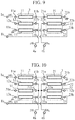
- FIG. 9 is a configuration diagram illustrating an in-phase suppression circuit according to the fourth embodiment of the present invention.
- the first line 11 and the second line 12 included in the first coupled lines 2, and the fourth line 21 and the fifth line 22 included in the second coupled lines 3 form a first Marchand balun like in the first embodiment.
- the second line 12 and the third line 13 included in the first coupled lines 2, and the fifth line 22 and the sixth line 23 included in the second coupled lines 3 form a second Marchand balun like in the first embodiment.
- the second line 12 coupled to the first signal output terminal 4a is shared by the first Marchand balun and the second Marchand balun.
- the fifth line 22 coupled to the second signal output terminal 4b is shared by the first Marchand balun and the second Marchand balun like in the first embodiment.
- the present embodiment is similar to the first embodiment in that the first line 11, the second line 12, the fourth line 21, and the fifth line 22 form the first Marchand balun.
- the first Marchand balun in the fourth embodiment is different from the first Marchand balun in the first embodiment in the state of some ends of the lines.
- the other end 21b of the fourth line 21 is open, the one end 12a of the second line 12 is grounded, the other end 22b of the fifth line 22 is grounded, and the one end 13a of the third line 13 is open.
- the other end 21b of the fourth line 21 is grounded, the one end 12a of the second line 12 is open, the other end 22b of the fifth line 22 is open, and the one end 13a of the third line 13 is grounded.
- differential signals are output from the first signal output terminal 4a and the second signal output terminal 4b, and no in-phase component is output from the first signal output terminal 4a or the second signal output terminal 4b.
- the first line 11 having one end 11a coupled to the first signal input terminal 1a; the second line 12 having one end 12a open and the other end 12b coupled to the first signal output terminal 4a, the second line 12 electromagnetically coupled to the first line 11; the third line 13 having one end 13a grounded, the third line 13 electromagnetically coupled to the second line 12; the fourth line 21 having one end 21a coupled to the other end 11b of the first line 11 and the other end 21b grounded; the fifth line 22 having one end 22a coupled to the second signal output terminal 4b and the other end 22b open, the fifth line 22 electromagnetically coupled to the fourth line 21; and the sixth line 23 having one end 23a coupled to the other end 13b of the third line 13 and the other end 23b coupled to the second signal input terminal 1b, the sixth line 23 electromagnetically coupled to the fifth line 22.
- first line 11, the second line 12, the third line 13, the fourth line 21, the fifth line 22, and the sixth line 23 have a length of a quarter wavelength at a frequency of signals input from the first signal input terminal 1a and the second signal input terminal 1b.
- the in-phase suppression circuit disclosed in Non-Patent Literature 1 includes eight transmission lines, whereas in the fourth embodiment, the number of transmission lines included in the in-phase suppression circuit is six. The number of transmission lines has decreased by two.
- the other end 21b of the fourth line 21 is grounded, the one end 12a of the second line 12 is open, the other end 22b of the fifth line 22 is open, and the one end 13a of the third line 13 is grounded.
- FIG. 10 is a configuration diagram illustrating an in-phase suppression circuit according to the fifth embodiment of the present invention.
- the first line 11, the second line 12, and the seventh line 31 included in the first coupled lines 2 and the fourth line 21, the fifth line 22, and the eighth line 32 included in the second coupled lines 3 form a first Marchand balun.
- the second line 12, the seventh line 31, and the third line 13 included in the first coupled lines 2, and the fifth line 22, the eighth line 32, and the sixth line 23 included in the second coupled lines 3 form a second Marchand balun.
- the second line 12 and the seventh line 31 coupled to the first signal output terminal 4a are shared by the first Marchand balun and the second Marchand balun.
- the fifth line 22 and the eighth line 32 coupled to the second signal output terminal 4b are shared by the first Marchand balun and the second Marchand balun.
- the present embodiment is similar to the second embodiment in that the first line 11, the second line 12, the seventh line 31, the fourth line 21, the fifth line 22, and the eighth line 32 form the first Marchand balun.
- the first Marchand balun in the fifth embodiment is different from the first Marchand balun in the second embodiment in the state of some ends of the lines.
- the other end 21b of the fourth line 21 is open, the one end 12a of the second line 12 is grounded, the other end 22b of the fifth line 22 is grounded, and the one end 13a of the third line 13 is open. Moreover, the one end 31a of the seventh line 31 is grounded, and the other end 32b of the eighth line 32 is grounded.
- the other end 21b of the fourth line 21 is grounded, the one end 12a of the second line 12 is open, the other end 22b of the fifth line 22 is open, and the one end 13a of the third line 13 is grounded.
- the one end 31a of the seventh line 31 is open, and the other end 32b of the eighth line 32 is open.
- differential signals are output from the first signal output terminal 4a and the second signal output terminal 4b, and no in-phase component is output from the first signal output terminal 4a or the second signal output terminal 4b.
- the seventh line 31 having the one end 31a open and the other end 31b coupled to the first signal output terminal 4a, the seventh line 31 arranged between the second line 12 and the third line 13 and electromagnetically coupled to each of the second line 12 and the third line 13; and the eighth line 32 having the one end 32a coupled to the second signal output terminal 4b and the other end 32b open, the eighth line 32 arranged between the fifth line 22 and the sixth line 23 and electromagnetically coupled to each of the fifth line 22 and the sixth line 23, and each of the seventh line 31 and the eighth line 32 has a length of a quarter wavelength at the center frequency of the signal DS 1 and the signal DS 2 .
- the conventional in-phase suppression circuit illustrated in FIG. 5 includes twelve transmission lines, whereas in the fifth embodiment, the number of transmission lines included in the in-phase suppression circuit is eight. The number of transmission lines has decreased by four.
- the example has been described in which the one end 31a of the seventh line 31 is grounded, the other end 32b of the eighth line 32 is grounded, and the other end 42b of the tenth line 42 is open.
- the other end 21b of the fourth line 21 is grounded, the one end 12a of the second line 12 is open, the other end 22b of the fifth line 22 is open, and the one end 13a of the third line 13 is grounded.
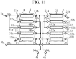
- FIG. 11 is a configuration diagram illustrating an in-phase suppression circuit according to the sixth embodiment of the present invention.
- the first line 11, the second line 12, the ninth line 41, and the seventh line 31 included in the first coupled lines 2 and the fourth line 21, the fifth line 22, the tenth line 42, and the eighth line 32 included in the second coupled lines 3 form a first Marchand balun.
- the second line 12, the ninth line 41, the seventh line 31, and the third line 13 included in the first coupled lines 2, and the fifth line 22, the tenth line 42, the eighth line 32, and the sixth line 23 included in the second coupled lines 3 form a second Marchand balun.
- the second line 12, the ninth line 41, and the seventh line 31 coupled to the first signal output terminal 4a are shared by the first Marchand balun and the second Marchand balun.
- the fifth line 22, the tenth line 42, and the eighth line 32 coupled to the second signal output terminal 4b are shared by the first Marchand balun and the second Marchand balun.
- the present embodiment is similar to the third embodiment in that the first line 11, the second line 12, the ninth line 41, the seventh line 31, the fourth line 21, the fifth line 22, the tenth line 42, and the eighth line 32 form the first Marchand balun.
- the first Marchand balun in the sixth embodiment is different from the first Marchand balun in the third embodiment in the state of some ends of the lines.
- the other end 21b of the fourth line 21 is open, the one end 12a of the second line 12 is grounded, the other end 22b of the fifth line 22 is grounded, and the one end 13a of the third line 13 is open.
- the one end 31a of the seventh line 31 is grounded, the other end 32b of the eighth line 32 is grounded, and the other end 42b of the tenth line 42 is open.
- the other end 21b of the fourth line 21 is grounded, the one end 12a of the second line 12 is open, the other end 22b of the fifth line 22 is open, and the one end 13a of the third line 13 is grounded.
- the one end 31a of the seventh line 31 is open, the other end 32b of the eighth line 32 is open, and the other end 42b of the tenth line 42 is grounded.
- differential signals are output from the first signal output terminal 4a and the second signal output terminal 4b, and no in-phase component is output from the first signal output terminal 4a and the second signal output terminal 4b.
- the ninth line 41 having the one end 41a coupled to the first signal input terminal 1a and the other end 41b coupled to the other end 11b of the first line 11, the ninth line 41 arranged between the second line 12 and the seventh line 31 and electromagnetically coupled to each of the second line 12 and the seventh line 31; and the tenth line 42 having the one end 42a coupled to the one end 21a of the fourth line 21 and the other end 42b grounded, the tenth line 42 arranged between the fifth line 22 and the eighth line 32 and electromagnetically coupled to each of the fifth line 22 and the eighth line 32, and each of the ninth line 41 and the tenth line 42 have a length of a quarter wavelength at the center frequency of the signal DS 1 and the signal DS 2 .
- the in-phase suppression circuit illustrated in FIG. 7 includes sixteen transmission lines, whereas in the sixth embodiment, the number of transmission lines included in the in-phase suppression circuit is ten. The number of transmission lines has decreased by six.
- the present invention may include a flexible combination of the respective embodiments, a modification of any component of the embodiments, or an omission of any component in the embodiments within the scope of the present invention.
- the present invention is suitable for an in-phase suppression circuit including a plurality of lines having a length of a quarter wavelength at a frequency of an input signal.
Landscapes
- Cable Transmission Systems, Equalization Of Radio And Reduction Of Echo (AREA)
- Noise Elimination (AREA)
Abstract
Description
- The present invention relates to an in-phase suppression circuit including a plurality of lines having a length of a quarter wavelength at a frequency of an input signal.
- For example, there are cases each in which a differential signal is used for signal transmission in an in-phase suppression circuitused in microwave band circuits or millimeter wave band circuits.
- The transmission scheme using a differential signal is to transmit signals the same in amplitude as each other but phases thereof are different from each other and shifted by 180 degrees on two signal lines, and is capable of superimposing information on a difference in the potential between the signals on the two signal lines.
- Therefore, a device on the receiving side of the differential signal acquires the information by detecting the difference in the potential between the signals on the two signal lines.
- Here, since the difference in the potential between the signals on the two signal lines does not change even if in-phase noise is applied to the two signal lines, the transmission quality is not affected.
- However, the two signals constituting the differential signal ideally have the same amplitude but reversed phases. However, in a case where an in-phase component is superimposed, which is called a common mode, an amplitude difference and a phase difference may be generated.
- Each of the amplitude difference and the phase difference between the two signals constituting the differential signal causes the balance of the differential signal to be lost, thereby contributing to unnecessary oscillation, a spurious, or non-linearity.
- Therefore, it is necessary to remove the superimposed in-phase component, and a differential amplifier having a high rejection ratio of the common mode is used as one of the methods of removing the in-phase component.
- However, in a case where a differential amplifier having a high rejection ratio of the common mode, there are cases where in microwave bands or millimeter wave bands, a balun is employed which performs conversion between a balanced signal an unbalanced signal since it is necessary to suppress signal distortion caused by the differential amplifier or noise generated from the differential amplifier.
- Non-Patent Literature 1 below discloses an in-phase suppression circuit including a first Marchand balun and a second Marchand balun as baluns for converting between a balanced signal and an unbalanced signal.
- As described below, the first Marchand balun includes first to fourth transmission lines having a length of a quarter wavelength at a frequency of an input signal.
- (1) First transmission line having one end coupled to a first signal input terminal.
- (2) Second transmission line having one end grounded and the other end coupled to a second signal output terminal, the second transmission line being electromagnetically coupled to the first transmission line.
- (3) Third transmission line having one end coupled to the other end of the first transmission line and the other end open.
- (4) Fourth transmission line having one end coupled to a first signal output terminal and the other end grounded, the fourth transmission line electromagnetically coupled to the third transmission line.
- As described below, the second Marchand balun includes fifth to eighth transmission lines having a length of a quarter wavelength at a frequency of an input signal.
- (1) Fifth transmission line having one end coupled to a second signal input terminal.
- (2) Sixth transmission line having one end grounded and the other end coupled to the first signal output terminal, the sixth transmission line electromagnetically coupled to the fifth transmission line.
- (3) Seventh transmission line having one end coupled to the other end of the fifth transmission line and the other end open.
- (4) Eighth transmission line having one end coupled to the second signal output terminal and the other end grounded, the eighth transmission line electromagnetically coupled to the seventh transmission line.
- In this in-phase suppression circuit, when a differential signal is input from the first signal input terminal and the second signal input terminal, a differential signal is output from the first signal output terminal and the second signal output terminal.
- In-phase signals input from the first signal input terminal and the second signal input terminal are canceled out, and thus are not output from the first signal output terminal and the second signal output terminal.
- Non-Patent Literature 1:
K.S. Ang and I. D. Rebertson, "Analysis and Design of Impedance-Transforming Planar Marchand Baluns," IEEE Trans. On Microwave Theory and Techniques, vol. 49, no. 2, pp. 402-406, Feb. 2001. - Since the conventional in-phase suppression circuit is configured as described above, it is possible to suppress output of in-phase signals from the first signal output terminal and the second signal output terminal.
- However, there is a disadvantage that it is necessary to mount eight transmission lines having a length of a quarter wavelength at a frequency of an input signal.
- The present invention has been made to solve the above disadvantage, and it is an object of the present invention to obtain an in-phase suppression circuit capable of reducing the number of transmission lines compared to the case of using two Marchand baluns that are independent of each other.
- An in-phase suppression circuit according to the present invention includes: a first line in which one end thereof is coupled to a first signal input terminal; a second line in which one end thereof is grounded and the other end thereof is coupled to a first signal output terminal, the second line being electromagnetically coupled to the first line; a third line in which one end thereof is open, the third line being electromagnetically coupled to the second line; a fourth line in which one end thereof is coupled to the other end of the first line and the other end is open; a fifth line in which one end thereof is coupled to a second signal output terminal and the other end thereof is grounded, the fifth line being electromagnetically coupled to the fourth line; and a sixth line in which one end thereof is coupled to the other end of the third line and the other end thereof is coupled to a second signal input terminal, the sixth line being electromagnetically coupled to the fifth line, wherein the first to sixth lines have a length of a quarter wavelength at a frequency of signals input from the first and second signal input terminals.
- According to this invention, since the in-phase suppression circuit includes: a first line in which one end thereof is coupled to a first signal input terminal; a second line in which one end thereof is grounded and the other end thereof is coupled to a first signal output terminal, the second line being electromagnetically coupled to the first line; a third line in which one end thereof is open, the third line being electromagnetically coupled to the second line; a fourth line in which one end thereof is coupled to the other end of the first line and the other end is open; a fifth line in which one end thereof is coupled to a second signal output terminal and the other end thereof is grounded, the fifth line being electromagnetically coupled to the fourth line; and a sixth line in which one end thereof is coupled to the other end of the third line and the other end is coupled to a second signal input terminal, the sixth line being electromagnetically coupled to the fifth line. Therefore, there is an effect of reducing the number of transmission lines as compared with the case of using two Marchand balun independent of each other.
-
-
FIG. 1 is a configuration diagram illustrating an in-phase suppression circuit according to a first embodiment of the present invention. -
FIG. 2 is an explanatory graph illustrating the amplitude of an S parameter S21 and the amplitude of an S parameter S31 when a differential signal is input. -
FIG. 3 is an explanatory graph illustrating a phase difference between the S parameter S21 and the S parameter S31 when a differential signal is input. -
FIG. 4 is an explanatory graph illustrating the amplitude of an S parameter S54 and the amplitude of an S parameter S64 when in-phase signals are input. -
FIG. 5 is a configuration diagram illustrating a conventional in-phase suppression circuit including a first Marchand balun including first to sixth transmission lines and a second Marchand balun including seventh to twelfth transmission lines. -
FIG. 6 is a configuration diagram illustrating an in-phase suppression circuit according to a second embodiment of the present invention. -
FIG. 7 is a configuration diagram illustrating a conventional in-phase suppression circuit including a first Marchand balun including first to eighth transmission lines and a second Marchand balun including ninth to sixteenth transmission lines. -
FIG. 8 is a configuration diagram illustrating an in-phase suppression circuit according to a third embodiment of the present invention. -
FIG. 9 is a configuration diagram illustrating an in-phase suppression circuit according to a fourth embodiment of the present invention. -
FIG. 10 is a configuration diagram illustrating an in-phase suppression circuit according to a fifth embodiment of the present invention. -
FIG. 11 is a configuration diagram illustrating an in-phase suppression circuit according to a sixth embodiment of the present invention. - To describe the present invention further in detail, embodiments for carrying out the present invention will be described below with reference to the accompanying drawings.
-
FIG. 1 is a configuration diagram illustrating an in-phase suppression circuit according to a first embodiment of the present invention. - In
FIG. 1 , a first signal input terminal 1a is a terminal for inputting a signal DS1 in a microwave band or a millimeter wave band, for example. - A second
signal input terminal 1b is a terminal for inputting a signal DS2 of a microwave band or a millimeter wave band, for example. - The signal DS1 and the signal DS2 are the same in frequency as each other, and the phase of the signal DS1 is 180 degrees different from the phase of the signal DS2.
- Therefore, the signal DS1 and the signal DS2 constitute a differential signal. For convenience of explanation, it is assumed here that the phase of the signal DS1 is 0 degrees and that the phase of the signal DS2 is 180 degrees.
- The first coupled
lines 2 include afirst line 11, asecond line 12, and athird line 13. - Each of the
first line 11, thesecond line 12, and thethird line 13 has a length of a quarter wavelength at the center frequency of the signal DS1 and the signal DS2. - The
first line 11 is a transmission line having oneend 11a coupled to the first signal input terminal 1a. - The
second line 12 is a transmission line having oneend 12a grounded and theother end 12b coupled to a firstsignal output terminal 4a, and is electromagnetically coupled to thefirst line 11. - The
third line 13 is a transmission line that is open at oneend 13a and electromagnetically coupled to thesecond line 12. - The second coupled lines 3 include a
fourth line 21, afifth line 22, and asixth line 23. - Each of the
fourth line 21, thefifth line 22, and thesixth line 23 has a length of a quarter wavelength at the center frequency of the signal DS1 and the signal DS2. - The
fourth line 21 is a transmission line having oneend 21a coupled to theother end 11b of thefirst line 11 and theother end 21b open. - The
fifth line 22 is a transmission line in which oneend 22a is coupled to a secondsignal output terminal 4b and theother end 22b is grounded, and is electromagnetically coupled to thefourth line 21. - The
sixth line 23 is a transmission line having oneend 23a coupled to theother end 13b of thethird line 13 and theother end 23b coupled to the secondsignal input terminal 1b, and is electromagnetically coupled to thefifth line 22. - The first
signal output terminal 4a outputs a signal DS3 output from the first coupledlines 2. - The second
signal output terminal 4b outputs a signal DS4 output from the second coupled lines 3. - Next, the operation will be described.
- In the in-phase suppression circuit in
FIG. 1 , thefirst line 11 and thesecond line 12 included in the first coupledlines 2, and thefourth line 21 and thefifth line 22 included in the second coupled lines 3 form a first Marchand balun. In the first embodiment, the passing phase of the first Marchand balun is θ. - Meanwhile, in the in-phase suppression circuit in
FIG. 1 , thesecond line 12 and thethird line 13 included in the first coupledlines 2, and thefifth line 22 and thesixth line 23 included in the second coupled lines 3 form a second Marchand balun. In the first embodiment, the passing phase of the second Marchand balun is θ. - The
second line 12 coupled to the firstsignal output terminal 4a is shared by the first Marchand balun and the second Marchand balun. - The
fifth line 22 coupled to the secondsignal output terminal 4b is shared by the first Marchand balun and the second Marchand balun. - Since the
first line 11, thesecond line 12, thefourth line 21, and thefifth line 22 form the first Marchand balun, when the signal DS1 is input from the first signal input terminal 1a, a signal DS1-1 having a phase of (0 + θ) degrees appears at theother end 12b of thesecond line 12. - Furthermore, a signal DS1-2 having a phase of (180 + θ) degrees appears at one
end 22a of thefifth line 22. - Since the
second line 12, thethird line 13, thefifth line 22, and thesixth line 23 form the second Marchand balun, when the signal DS2 is input from the secondsignal input terminal 1b, a signal DS2-1 having a phase of (180 + θ) degree appears at oneend 22a of thefifth line 22. - Furthermore, a signal DS2-2 having a phase of (0 + θ) degrees appears at the
other end 12b of thesecond line 12. - Here, the signal DS1-1 and the signal DS2-2 appearing at the
other end 12b of thesecond line 12 are in-phase combined since they both have the phase of (0 + θ) degrees. - As a result, the signal DS3 having the phase of (0 + θ) degrees is output from the first
signal output terminal 4a as a composite signal of the signals DS1-1 and DS2-2. - Moreover, the signal DS1-2 and the signal DS2-1 appearing at the one
end 22a of thefifth line 22 are also in-phase combined since they both have the phase of (180 + θ) degrees. - As a result, the signal DS4 having the phase of (180 + θ) degrees is output from the second
signal output terminal 4b as a composite signal of the signals DS1-2 and DS2-1. - Since the phase difference between the signal DS3 output from the first
signal output terminal 4a and the signal DS4 output from the secondsignal output terminal 4b is 180 degrees, the signal DS3 and the signal DS4 are differential signals. - Next, the operation when an in-phase signal C such as noise is input from the first signal input terminal 1a and the second
signal input terminal 1b will be described. - Here, for convenience of explanation, it is assumed that the phase of the in-phase signal C is α.
- Since the
first line 11, thesecond line 12, thefourth line 21, and thefifth line 22 form the first Marchand balun, when the in-phase signal C is input from the first signal input terminal 1a, a signal C1-1 having a phase of (α + θ) degrees appears at theother end 12b of thesecond line 12. - A signal C1-2 having a phase of (180 + α + θ) degrees also appears at the one
end 22a of thefifth line 22. - Since the
second line 12, thethird line 13, thefifth line 22, and thesixth line 23 form the second Marchand balun, when the in-phase signal C is input from the secondsignal input terminal 1b, a signal C2-1 having a phase of (α + θ) degree appears at the oneend 22a of thefifth line 22. - A signal C2-2 having a phase of (180 + α + θ) also appears at the
other end 12b of thesecond line 12. - Here, the signal C1-1 and the signal C2-2 appearing at the
other end 12b of thesecond line 12 are canceled out since they have a phase difference of 180 degrees (= |(α + 8) - (180 + α + θ)|) and they are the same in amplitude as each other. - Likewise, the signal C1-2 and the signal C2-1 appearing at the one
end 22a of thefifth line 22 are also canceled out since they have a phase difference of 180 degrees (= |(180 + α + θ) - (α + θ)|) and they are the same in amplitude as each other. - As a result, no in-phase component is output from the first
signal output terminal 4a or the secondsignal output terminal 4b. - Next, characteristics when differential signals and in-phase signals are input to the in-phase suppression circuit of
FIG. 1 will be described. - Here, in a case where differential signals are input to the first
signal output terminal 4a and the secondsignal output terminal 4b, balanced signal terminals of an ideal balun capable of generating differential signals are coupled to the firstsignal output terminal 4a and the secondsignal output terminal 4b. - Meanwhile, assuming an unbalanced signal terminal of the ideal balun as a port (1) of a characteristic calculation circuit, an unbalanced signal is input to the port (1).
- In addition, assuming the first
signal output terminal 4a as a port (2) of the characteristic calculation circuit and the secondsignal output terminal 4b as a port (3) of the characteristic calculation circuit, an S parameter S21 between the port (1) and the port (2) as well as an S parameter S31 between the port (1) and the port (3) are calculated. - Next, in a case where in-phase signals are input to the first
signal output terminal 4a and the secondsignal output terminal 4b, the firstsignal output terminal 4a and the secondsignal output terminal 4b are coupled, and an unbalanced signal is input to a port (4) of the characteristic calculation circuit. - In addition, assuming the first
signal output terminal 4a as a port (5) of the characteristic calculation circuit and the secondsignal output terminal 4b as a port (6) of the characteristic calculation circuit, an S parameter S54 between the port (4) and the port (5) as well as an S parameter S64 between the port (4) and the port (6) are calculated. -
FIG. 2 is an explanatory graph illustrating the amplitude of the S parameter S21 and the amplitude of the S parameter S31 when differential signals are input. -
FIG. 3 is an explanatory graph illustrating a phase difference between the S parameter S21 and the S parameter S31 when differential signals are input. - In
FIGS. 2 and3 , the lengths of thefirst line 11, thesecond line 12, thethird line 13, thefourth line 21, thefifth line 22, and thesixth line 23 are each set to a quarter wavelength at 20 GHz. - For this reason, as illustrated in
FIG. 2 it can be seen that a passage loss in the in-phase suppression circuit is about -3 dB around a frequency of 20 GHz and that the differential signal is transmitted with almost no loss. - Also as illustrated in
FIG. 3 , it can be seen that a phase difference between the S parameter S21 and the S parameter S31 is 180 degrees at the frequency of 20 GHz and that transmission as differential signals is carried out. -
FIG. 4 is an explanatory graph illustrating the amplitude of the S parameter S54 and the amplitude of the S parameter S64 when in-phase signals are input. - As can be seen from
FIG. 4 , in-phase signals are attenuated by about 20 dB at the frequency of 20 GHz. - As apparent from the above, according to the first embodiment, included are: the
first line 11 having oneend 11a coupled to the first signal input terminal 1a; thesecond line 12 having oneend 12a grounded and theother end 12b coupled to the firstsignal output terminal 4a, thesecond line 12 electromagnetically coupled to thefirst line 11; thethird line 13 having oneend 13a open, thethird line 13 electromagnetically coupled to thesecond line 12; thefourth line 21 having oneend 21a coupled to theother end 11b of thefirst line 11 and theother end 21b open; afifth line 22 having oneend 22a coupled to the secondsignal output terminal 4b and theother end 22b grounded, thefifth line 22 electromagnetically coupled to thefourth line 21; and thesixth line 23 having oneend 23a coupled to theother end 13b of thethird line 13 and theother end 23b coupled to the secondsignal input terminal 1b, thesixth line 23 electromagnetically coupled to thefifth line 22. - Moreover, the
first line 11, thesecond line 12, thethird line 13, thefourth line 21, thefifth line 22, and thesixth line 23 have a length of a quarter wavelength at a frequency of signals input from the first signal input terminal 1a and the secondsignal input terminal 1b. - This exerts the effect of reducing the number of transmission lines as compared with a case of using two Marchand baluns that are independent of each other.
- For example, the in-phase suppression circuit disclosed in Non-Patent Literature 1 includes eight transmission lines, whereas in the first embodiment, the number of transmission lines included in the in-phase suppression circuit is six. The number of transmission lines has decreased by two.
- Therefore, in the first embodiment, it is possible to miniaturize the in-phase suppression circuit disclosed in Non-Patent Literature 1.
- In the first embodiment, it is assumed that the
first line 11, thesecond line 12, thethird line 13, thefourth line 21, thefifth line 22, thesixth line 23 are arranged on a plane of a dielectric substrate including an integrated circuit (IC). - However, the
first line 11, thesecond line 12, thethird line 13, thefourth line 21, thefifth line 22, and thesixth line 23 is not limited to the arrangement on the plane of a dielectric substrate. - For example, in a multilayer dielectric substrate including an IC, the
first line 11, thesecond line 12, thethird line 13, thefourth line 21, thefifth line 22, and thesixth line 23 may be distributed to a plurality of layers, and lines arranged in different layers may be electromagnetically coupled to. - In the in-phase suppression circuit disclosed in Non-Patent Literature 1, the first Marchand balun includes the first to fourth transmission lines, and the second Marchand balun includes the fifth to eighth transmission lines.
- There are cases where the manufacture becomes difficult if the distance between the lines is extremely narrow when the first to eighth transmission lines are formed on a dielectric substrate.
- As illustrated in
FIG. 5 , adding one transmission line to each of the coupled lines in the first and second Marchand baluns makes it possible to configure the first and second Marchand baluns even in a case where the amount of coupling between adjacent lines is reduced. - If the first and second Marchand baluns can be configured even in a case where the amount of coupling between adjacent lines is reduced, the distance between the lines can be increased, thereby facilitating manufacturing.
-
FIG. 5 is a configuration diagram illustrating a conventional in-phase suppression circuit including a first Marchand balun including first to sixth transmission lines and a second Marchand balun including seventh to twelfth transmission lines. - The first to twelfth transmission lines have a length of a quarter wavelength at the frequency of input differential signals.
-
FIG. 6 is a configuration diagram illustrating an in-phase suppression circuit according to a second embodiment of the present invention. InFIG. 6 , the same symbol as that inFIG. 1 represents the same or a corresponding part and thus descriptions thereof are omitted. - A
seventh line 31 is a transmission line having oneend 31a grounded and theother end 31b coupled to the firstsignal output terminal 4a. Theseventh line 31 is arranged between thesecond line 12 and thethird line 13 and is electromagnetically coupled to each of thesecond line 12 and thethird line 13. - An
eighth line 32 is a transmission line having oneend 32a coupled to the secondsignal output terminal 4b and theother end 32b grounded. Theeighth line 32 is arranged between thefifth line 22 and thesixth line 23 and is electromagnetically coupled to each of thefifth line 22 and thesixth line 23. - Each of the
seventh line 31 and theeighth line 32 has a length of a quarter wavelength at the center frequency of the signal DS1 and the signal DS2. - Next, the operation will be described.
- In the in-phase suppression circuit in
FIG. 6 , thefirst line 11, thesecond line 12, and theseventh line 31 included in the first coupledlines 2, and thefourth line 21, thefifth line 22, and theeighth line 32 included in the second coupled lines 3 form a first Marchand balun. - Meanwhile, in the in-phase suppression circuit in
FIG. 6 , thesecond line 12, theseventh line 31, and thethird line 13 included in the first coupledlines 2, and thefifth line 22, theeighth line 32, and thesixth line 23 included in the second coupled lines 3 form a second Marchand balun. - The
second line 12 and theseventh line 31 coupled to the firstsignal output terminal 4a are shared by the first Marchand balun and the second Marchand balun. - The
fifth line 22 and theeighth line 32 coupled to the secondsignal output terminal 4b are shared by the first Marchand balun and the second Marchand balun. - Since the
first line 11, thesecond line 12, theseventh line 31, thefourth line 21, thefifth line 22, and theeighth line 32 form the first Marchand balun, when the signal DS1 is input from the first signal input terminal 1a, a signal DS1-1 having a phase of (0 + θ) degrees appears at theother end 12b of thesecond line 12 and theother end 31b of theseventh line 31. - Furthermore, a signal DS1-2 having a phase of (180 + θ) degrees appears at the one
end 22a of thefifth line 22 and the oneend 32a of theeighth line 32. - Since the
second line 12, theseventh line 31, thethird line 13, thefifth line 22, theeighth line 32, and thesixth line 23 form the second Marchand balun, when the signal DS2 is input from the secondsignal input terminal 1b, a signal DS2-1 having a phase of (180 + θ) degrees appears at the oneend 22a of thefifth line 22 and the oneend 32a of theeighth line 32. - Furthermore, a signal DS2-2 having a phase of (0 + θ) degrees appears at the
other end 12b of thesecond line 12 and theother end 31b of theseventh line 31. - Here, the signal DS1-1 and the signal DS2-2 appearing at the
other end 12b of thesecond line 12 and theother end 31b of theseventh line 31 are in-phase combined since they both have the phase of (0 + θ) degrees. - As a result, the signal DS3 having the phase of (0 + θ) degrees is output from the first
signal output terminal 4a as a composite signal of the signals DS1-1 and DS2-2. - Moreover, the signal DS1-2 and the signal DS2-1 appearing at the one
end 22a of thefifth line 22 and the oneend 32a of theeighth line 32 are also in-phase combined since they both have the phase of (180 + θ) degrees. - As a result, the signal DS4 having the phase of (180 + θ) degrees is output from the second
signal output terminal 4b as a composite signal of the signals DS1-2 and DS2-1. - Since the phase difference between the signal DS3 output from the first
signal output terminal 4a and the signal DS4 output from the secondsignal output terminal 4b is 180 degrees, the signal DS3 and the signal DS4 are differential signals. - Next, the operation when an in-phase signal C such as noise is input from the first signal input terminal 1a and the second
signal input terminal 1b will be described. - Since the
first line 11, thesecond line 12, theseventh line 31, thefourth line 21, thefifth line 22, and theeighth line 32 form the first Marchand balun, when an in-phase signal C is input from the first signal input terminal 1a, a signal C1-1 having a phase of (α + θ) degrees appears at theother end 12b of thesecond line 12 and theother end 31b of theseventh line 31. - In addition, a signal C1-2 having a phase of (180 + α + θ) degrees appears at the one
end 22a of thefifth line 22 and the oneend 32a of theeighth line 32. - Since the
second line 12, theseventh line 31, thethird line 13, thefifth line 22, theeighth line 32, and thesixth line 23 form the second Marchand balun, when the in-phase signal C is input from the secondsignal input terminal 1b, a signal C2-1 having a phase of (α + θ) degrees appears at the oneend 22a of thefifth line 22 and the oneend 32a of theeighth line 32. - Furthermore, a signal C2-2 having a phase of (180 + α + θ) appears at the
other end 12b of thesecond line 12 and theother end 31b of theseventh line 31. - Here, the signal C1-1 and the signal C2-2 appearing at the
other end 12b of thesecond line 12 and theother end 31b of theseventh line 31 are canceled out since they have a phase difference of 180 degrees (= |(α + θ) - (180 + α + θ)|) and they are the same in amplitude as each other. - Likewise, the signal C1-2 and the signal C2-1 appearing at the one
end 22a of thefifth line 22 and the oneend 32a of theeighth line 32 are also canceled out since they have a phase difference of 180 degrees (= |(180 + α + θ) - (α + θ)|) and they are the same in amplitude as each other. - As a result, no in-phase component is output from the first
signal output terminal 4a or the secondsignal output terminal 4b. - In the in-phase suppression circuit in
FIG. 6 , theseventh line 31 is added to the first coupledlines 2, and theeighth line 32 is added to the second coupled lines 3, and thus it is possible to configure the first and second Marchand baluns even in a case where the amount of coupling between adjacent lines is reduced like in the conventional in-phase suppression circuit illustrated inFIG. 5 . - If the first and second Marchand baluns can be configured even in a case where the amount of coupling between adjacent lines is reduced, the distance between the lines can be increased, thereby facilitating manufacturing.
- As is apparent from the above, according to the second embodiment, further included are: the
seventh line 31 having oneend 31a grounded and theother end 31b coupled to the firstsignal output terminal 4a, theseventh line 31 arranged between thesecond line 12 and thethird line 13 and electromagnetically coupled to each of thesecond line 12 and thethird line 13; and theeighth line 32 having oneend 32a coupled to the secondsignal output terminal 4b and theother end 32b grounded, theeighth line 32 arranged between thefifth line 22 and thesixth line 23 and electromagnetically coupled to each of thefifth line 22 and thesixth line 23, and each of theseventh line 31 and theeighth line 32 has a length of a quarter wavelength at the center frequency of the signal DS1 and the signal DS2. - This exerts the effect of reducing the number of transmission lines as compared with a case of using two Marchand baluns that are independent of each other.
- For example, the conventional in-phase suppression circuit illustrated in
FIG. 5 includes twelve transmission lines, whereas in the second embodiment, the number of transmission lines included in the in-phase suppression circuit is eight. The number of transmission lines has decreased by four. - Therefore, in the second embodiment it is further possible to miniaturize the conventional in-phase suppression circuit illustrated in
FIG. 5 . - In the in-phase suppression circuit disclosed in Non-Patent Literature 1, the first Marchand balun includes the first to fourth transmission lines, and the second Marchand balun includes the fifth to eighth transmission lines.
- There are cases where the manufacture becomes difficult if the distance between the lines is extremely narrow when the first to eighth transmission lines are formed on a dielectric substrate.
- As illustrated in
FIG. 7 , adding two transmission lines to each of the coupled lines in the first and second Marchand baluns makes it possible to configure the first and second Marchand baluns even in a case where the amount of coupling between adjacent lines is reduced. - If the first and second Marchand baluns can be configured even in a case where the amount of coupling between adjacent lines is reduced, the distance between the lines can be increased, thereby facilitating manufacturing.
-
FIG. 7 is a configuration diagram illustrating a conventional in-phase suppression circuit including a first Marchand balun including first to eighth transmission lines and a second Marchand balun including ninth to sixteenth transmission lines. - The first to sixteenth transmission lines have a length of a quarter wavelength at the frequency of input differential signals.
-
FIG. 8 is a configuration diagram illustrating an in-phase suppression circuit according to the third embodiment of the present invention. InFIG. 8 , the same symbol as that inFIGS. 1 and6 represents the same or a corresponding part and thus descriptions thereof are omitted. - A
ninth line 41 is a transmission line having oneend 41a coupled to the first signal input terminal 1a and theother end 41b coupled to theother end 11b of thefirst line 11. Theninth line 41 is arranged between thesecond line 12 and theseventh line 31 and electromagnetically coupled to each of thesecond line 12 and theseventh line 31. - A
tenth line 42 is a transmission line having oneend 42a coupled to oneend 21a of thefourth line 21 and the other end 42b open. Thetenth line 42 is arranged between thefifth line 22 and theeighth line 32 and electromagnetically coupled to each of thefifth line 22 and theeighth line 32. - Each of the
ninth line 41 and thetenth line 42 has a length of a quarter wavelength at the center frequency of a signal DS1 and a signal DS2. - Next, the operation will be described.
- In the in-phase suppression circuit in
FIG. 8 , thefirst line 11, thesecond line 12, theninth line 41, and theseventh line 31 included in the first coupledlines 2, and thefourth line 21, thefifth line 22, thetenth line 42, and theeighth line 32 included in the second coupled lines 3 form a first Marchand balun. - In the in-phase suppression circuit in
FIG. 8 , thesecond line 12, theninth line 41, theseventh line 31, and thethird line 13 included in the first coupledlines 2, and thefifth line 22, thetenth line 42, theeighth line 32, and thesixth line 23 included in the second coupled lines 3 form a second Marchand balun. - The
second line 12, theninth line 41, and theseventh line 31 coupled to the firstsignal output terminal 4a are shared by the first Marchand balun and the second Marchand balun. - The
fifth line 22, thetenth line 42, and theeighth line 32 coupled to the secondsignal output terminal 4b are shared by the first Marchand balun and the second Marchand balun. - Since the
first line 11, thesecond line 12, theninth line 41, theseventh line 31, thefourth line 21, thefifth line 22, thetenth line 42, and theeighth line 32 form the first Marchand balun, when the signal DS1 is input from the first signal input terminal 1a, a signal DS1-1 having a phase of (0 + θ) degrees appears at theother end 12b of thesecond line 12 and theother end 31b of theseventh line 31. - Furthermore, a signal DS1-2 having a phase of (180 + θ) degrees appears at the one
end 22a of thefifth line 22 and the oneend 32a of theeighth line 32. - Since the
second line 12, theninth line 41, theseventh line 31, thethird line 13, thefifth line 22, thetenth line 42, theeighth line 32, and thesixth line 23 form the second Marchand balun, when the signal DS2 is input from the secondsignal input terminal 1b, a signal DS2-1 having a phase of (180 + θ) degrees appears at the oneend 22a of thefifth line 22 and the oneend 32a of theeighth line 32. - Furthermore, a signal DS2-2 having a phase of (0 + θ) degrees appears at the
other end 12b of thesecond line 12 and theother end 31b of theseventh line 31. - Here, the signal DS1-1 and the signal DS2-2 appearing at the
other end 12b of thesecond line 12 and theother end 31b of theseventh line 31 are in-phase combined since they both have the phase of (0 + θ) degrees. - As a result, the signal DS3 having the phase of (0 + θ) degrees is output from the first
signal output terminal 4a as a composite signal of the signals DS1-1 and DS2-2. - Moreover, the signal DS1-2 and the signal DS2-1 appearing at the one
end 22a of thefifth line 22 and the oneend 32a of theeighth line 32 are also in-phase combined since they both have the phase of (180 + θ) degrees. - As a result, the signal DS4 having the phase of (180 + θ) degrees is output from the second
signal output terminal 4b as a composite signal of the signals DS1-2 and DS2-1. - Since the phase difference between the signal DS3 output from the first
signal output terminal 4a and the signal DS4 output from the secondsignal output terminal 4b is 180 degrees, the signal DS3 and the signal DS4 are differential signals. - Next, the operation when an in-phase signal C such as noise is input from the first signal input terminal 1a and the second
signal input terminal 1b will be described. - Since the
first line 11, thesecond line 12, theninth line 41, theseventh line 31, thefourth line 21, thefifth line 22, thetenth line 42, and theeighth line 32 form the first Marchand balun, when an in-phase signal C is input from the first signal input terminal 1a, a signal C1-1 having a phase of (α + θ) degrees appears at theother end 12b of thesecond line 12 and theother end 31b of theseventh line 31. - In addition, a signal C1-2 having a phase of (180 + α + θ) degrees appears at the one
end 22a of thefifth line 22 and the oneend 32a of theeighth line 32. - Since the
second line 12, theninth line 41, theseventh line 31, thethird line 13, thefifth line 22, thetenth line 42, theeighth line 32, and thesixth line 23 form the second Marchand balun, when the in-phase signal C is input from the secondsignal input terminal 1b, a signal C2-1 having a phase of (α + θ) degrees appears at the oneend 22a of thefifth line 22 and the oneend 32a of theeighth line 32. - Furthermore, a signal C2-2 having a phase of (180 + α + θ) appears at the
other end 12b of thesecond line 12 and theother end 31b of theseventh line 31. - Here, the signal C1-1 and the signal C2-2 appearing at the
other end 12b of thesecond line 12 and theother end 31b of theseventh line 31 are canceled out since they have a phase difference of 180 degrees (= |(α + θ) - (180 + α + θ)|) and they are the same in amplitude as each other. - Likewise, the signal C1-2 and the signal C2-1 appearing at the one
end 22a of thefifth line 22 and the oneend 32a of theeighth line 32 are also canceled out since they have a phase difference of 180 degrees (= |(180 + α + θ) - (α + θ)|) and they are the same in amplitude as each other. - As a result, no in-phase component is output from the first
signal output terminal 4a or the secondsignal output terminal 4b. - In the in-phase suppression circuit in
FIG. 8 , theseventh line 31 and theninth line 41 are added to the first coupledlines 2, and theeighth line 32 and thetenth line 42 are added to the second coupled lines 3, and thus it is possible to configure the first and second Marchand baluns even in a case where the amount of coupling between adjacent lines is reduced like in the conventional in-phase suppression circuit illustrated inFIG. 7 . - If the first and second Marchand baluns can be configured even in a case where the amount of coupling between adjacent lines is reduced, the distance between the lines can be increased, thereby facilitating manufacturing.
- As is apparent from the above, according to the third embodiment, further included are: the
ninth line 41 having the oneend 41a coupled to the first signal input terminal 1a and theother end 41b coupled to theother end 11b of thefirst line 11, theninth line 41 arranged between thesecond line 12 and theseventh line 31 and electromagnetically coupled to each of thesecond line 12 and theseventh line 31; and thetenth line 42 having the oneend 42a coupled to the oneend 21a of thefourth line 21 and the other end 42b open, thetenth line 42 arranged between thefifth line 22 and theeighth line 32 and electromagnetically coupled to each of thefifth line 22 and theeighth line 32, and each of theninth line 41 and thetenth line 42 have a length of a quarter wavelength at the center frequency of the signal DS1 and the signal DS2. - This exerts the effect of reducing the number of transmission lines as compared with a case of using two Marchand baluns that are independent of each other.
- For example, the conventional in-phase suppression circuit illustrated in
FIG. 7 includes sixteen transmission lines, whereas in the third embodiment, the number of transmission lines included in the in-phase suppression circuit is ten. The number of transmission lines has decreased by six. - Therefore, in the third embodiment, it is further possible to miniaturize the conventional in-phase suppression circuit illustrated in
FIG. 7 . - In the first embodiment, the example has been described in which the
other end 21b of thefourth line 21 is open, the oneend 12a of thesecond line 12 is grounded, theother end 22b of thefifth line 22 is grounded, and the oneend 13a of thethird line 13 is open. - In a fourth embodiment, as illustrated in
FIG. 9 , an example will be described in which theother end 21b of thefourth line 21 is grounded, the oneend 12a of thesecond line 12 is open, theother end 22b of thefifth line 22 is open, and the oneend 13a of thethird line 13 is grounded. -
FIG. 9 is a configuration diagram illustrating an in-phase suppression circuit according to the fourth embodiment of the present invention. - In the in-phase suppression circuit in
FIG. 9 , thefirst line 11 and thesecond line 12 included in the first coupledlines 2, and thefourth line 21 and thefifth line 22 included in the second coupled lines 3 form a first Marchand balun like in the first embodiment. - In addition, in the in-phase suppression circuit in
FIG. 9 , thesecond line 12 and thethird line 13 included in the first coupledlines 2, and thefifth line 22 and thesixth line 23 included in the second coupled lines 3 form a second Marchand balun like in the first embodiment. - Like in the first embodiment, the
second line 12 coupled to the firstsignal output terminal 4a is shared by the first Marchand balun and the second Marchand balun. - The
fifth line 22 coupled to the secondsignal output terminal 4b is shared by the first Marchand balun and the second Marchand balun like in the first embodiment. - The present embodiment is similar to the first embodiment in that the
first line 11, thesecond line 12, thefourth line 21, and thefifth line 22 form the first Marchand balun. - The first Marchand balun in the fourth embodiment is different from the first Marchand balun in the first embodiment in the state of some ends of the lines.
- Specifically, in the first embodiment, the
other end 21b of thefourth line 21 is open, the oneend 12a of thesecond line 12 is grounded, theother end 22b of thefifth line 22 is grounded, and the oneend 13a of thethird line 13 is open. - In the fourth embodiment, the
other end 21b of thefourth line 21 is grounded, the oneend 12a of thesecond line 12 is open, theother end 22b of thefifth line 22 is open, and the oneend 13a of thethird line 13 is grounded. - However, the operation itself is similar for the first Marchand balun in the fourth embodiment and the first Marchand balun in the first embodiment.
- Therefore, like in the first embodiment, differential signals are output from the first
signal output terminal 4a and the secondsignal output terminal 4b, and no in-phase component is output from the firstsignal output terminal 4a or the secondsignal output terminal 4b. - As apparent from the above, according to the fourth embodiment, included are: the
first line 11 having oneend 11a coupled to the first signal input terminal 1a; thesecond line 12 having oneend 12a open and theother end 12b coupled to the firstsignal output terminal 4a, thesecond line 12 electromagnetically coupled to thefirst line 11; thethird line 13 having oneend 13a grounded, thethird line 13 electromagnetically coupled to thesecond line 12; thefourth line 21 having oneend 21a coupled to theother end 11b of thefirst line 11 and theother end 21b grounded; thefifth line 22 having oneend 22a coupled to the secondsignal output terminal 4b and theother end 22b open, thefifth line 22 electromagnetically coupled to thefourth line 21; and thesixth line 23 having oneend 23a coupled to theother end 13b of thethird line 13 and theother end 23b coupled to the secondsignal input terminal 1b, thesixth line 23 electromagnetically coupled to thefifth line 22. - Moreover, the
first line 11, thesecond line 12, thethird line 13, thefourth line 21, thefifth line 22, and thesixth line 23 have a length of a quarter wavelength at a frequency of signals input from the first signal input terminal 1a and the secondsignal input terminal 1b. - This exerts the effect of reducing the number of transmission lines as compared with a case of using two Marchand baluns that are independent of each other.
- For example, the in-phase suppression circuit disclosed in Non-Patent Literature 1 includes eight transmission lines, whereas in the fourth embodiment, the number of transmission lines included in the in-phase suppression circuit is six. The number of transmission lines has decreased by two.
- Therefore, in the fourth embodiment, it is possible to miniaturize the in-phase suppression circuit disclosed in Non-Patent Literature 1.
- In the second embodiment, the example has been described in which the
other end 21b of thefourth line 21 is open, the oneend 12a of thesecond line 12 is grounded, theother end 22b of thefifth line 22 is grounded, and the oneend 13a of thethird line 13 is open. - In the second embodiment, an example is described in which the one
end 31a of theseventh line 31 is grounded and theother end 32b of theeighth line 32 is grounded. - In the fifth embodiment, as illustrated in
FIG. 10 , theother end 21b of thefourth line 21 is grounded, the oneend 12a of thesecond line 12 is open, theother end 22b of thefifth line 22 is open, and the oneend 13a of thethird line 13 is grounded. - An example in which the one
end 31a of theseventh line 31 is open and theother end 32b of theeighth line 32 is open will be described. -
FIG. 10 is a configuration diagram illustrating an in-phase suppression circuit according to the fifth embodiment of the present invention. - Like in the second embodiment, in the in-phase suppression circuit in
FIG. 10 , thefirst line 11, thesecond line 12, and theseventh line 31 included in the first coupledlines 2 and thefourth line 21, thefifth line 22, and theeighth line 32 included in the second coupled lines 3 form a first Marchand balun. - Meanwhile, in the in-phase suppression circuit in
FIG. 10 , thesecond line 12, theseventh line 31, and thethird line 13 included in the first coupledlines 2, and thefifth line 22, theeighth line 32, and thesixth line 23 included in the second coupled lines 3 form a second Marchand balun. - The
second line 12 and theseventh line 31 coupled to the firstsignal output terminal 4a are shared by the first Marchand balun and the second Marchand balun. - The
fifth line 22 and theeighth line 32 coupled to the secondsignal output terminal 4b are shared by the first Marchand balun and the second Marchand balun. - The present embodiment is similar to the second embodiment in that the
first line 11, thesecond line 12, theseventh line 31, thefourth line 21, thefifth line 22, and theeighth line 32 form the first Marchand balun. - The first Marchand balun in the fifth embodiment is different from the first Marchand balun in the second embodiment in the state of some ends of the lines.
- Specifically, in the second embodiment, the
other end 21b of thefourth line 21 is open, the oneend 12a of thesecond line 12 is grounded, theother end 22b of thefifth line 22 is grounded, and the oneend 13a of thethird line 13 is open. Moreover, the oneend 31a of theseventh line 31 is grounded, and theother end 32b of theeighth line 32 is grounded. - In the fifth embodiment, the
other end 21b of thefourth line 21 is grounded, the oneend 12a of thesecond line 12 is open, theother end 22b of thefifth line 22 is open, and the oneend 13a of thethird line 13 is grounded. The oneend 31a of theseventh line 31 is open, and theother end 32b of theeighth line 32 is open. - However, the operation itself is similar for the first Marchand balun in the fifth embodiment and the first Marchand balun in the second embodiment.
- Therefore, like in the second embodiment, differential signals are output from the first
signal output terminal 4a and the secondsignal output terminal 4b, and no in-phase component is output from the firstsignal output terminal 4a or the secondsignal output terminal 4b. - As is apparent from the above, according to the fifth embodiment, further included are: the
seventh line 31 having the oneend 31a open and theother end 31b coupled to the firstsignal output terminal 4a, theseventh line 31 arranged between thesecond line 12 and thethird line 13 and electromagnetically coupled to each of thesecond line 12 and thethird line 13; and theeighth line 32 having the oneend 32a coupled to the secondsignal output terminal 4b and theother end 32b open, theeighth line 32 arranged between thefifth line 22 and thesixth line 23 and electromagnetically coupled to each of thefifth line 22 and thesixth line 23, and each of theseventh line 31 and theeighth line 32 has a length of a quarter wavelength at the center frequency of the signal DS1 and the signal DS2. - This exerts the effect of reducing the number of transmission lines as compared with a case of using two Marchand baluns that are independent of each other.
- For example, the conventional in-phase suppression circuit illustrated in
FIG. 5 includes twelve transmission lines, whereas in the fifth embodiment, the number of transmission lines included in the in-phase suppression circuit is eight. The number of transmission lines has decreased by four. - Therefore, in the fifth embodiment, it is further possible to miniaturize the conventional in-phase suppression circuit illustrated in
FIG. 5 . - In the third embodiment, the example has been described in which the
other end 21b of thefourth line 21 is open, the oneend 12a of thesecond line 12 is grounded, theother end 22b of thefifth line 22 is grounded, and the oneend 13a of thethird line 13 is open. - In the third embodiment, the example has been described in which the one
end 31a of theseventh line 31 is grounded, theother end 32b of theeighth line 32 is grounded, and the other end 42b of thetenth line 42 is open. - In this sixth embodiment, as illustrated in
FIG. 11 , theother end 21b of thefourth line 21 is grounded, the oneend 12a of thesecond line 12 is open, theother end 22b of thefifth line 22 is open, and the oneend 13a of thethird line 13 is grounded. - An example will be described in which the one
end 31a of theseventh line 31 is open, theother end 32b of theeighth line 32 is open, and the other end 42b of thetenth line 42 is grounded. -
FIG. 11 is a configuration diagram illustrating an in-phase suppression circuit according to the sixth embodiment of the present invention. - Like in the third embodiment, in the in-phase suppression circuit in
FIG. 11 , thefirst line 11, thesecond line 12, theninth line 41, and theseventh line 31 included in the first coupledlines 2 and thefourth line 21, thefifth line 22, thetenth line 42, and theeighth line 32 included in the second coupled lines 3 form a first Marchand balun. - In the in-phase suppression circuit in
FIG. 11 , thesecond line 12, theninth line 41, theseventh line 31, and thethird line 13 included in the first coupledlines 2, and thefifth line 22, thetenth line 42, theeighth line 32, and thesixth line 23 included in the second coupled lines 3 form a second Marchand balun. - The
second line 12, theninth line 41, and theseventh line 31 coupled to the firstsignal output terminal 4a are shared by the first Marchand balun and the second Marchand balun. - The
fifth line 22, thetenth line 42, and theeighth line 32 coupled to the secondsignal output terminal 4b are shared by the first Marchand balun and the second Marchand balun. - The present embodiment is similar to the third embodiment in that the
first line 11, thesecond line 12, theninth line 41, theseventh line 31, thefourth line 21, thefifth line 22, thetenth line 42, and theeighth line 32 form the first Marchand balun. - The first Marchand balun in the sixth embodiment is different from the first Marchand balun in the third embodiment in the state of some ends of the lines.
- Specifically, in the third embodiment, the
other end 21b of thefourth line 21 is open, the oneend 12a of thesecond line 12 is grounded, theother end 22b of thefifth line 22 is grounded, and the oneend 13a of thethird line 13 is open. The oneend 31a of theseventh line 31 is grounded, theother end 32b of theeighth line 32 is grounded, and the other end 42b of thetenth line 42 is open. - In the sixth embodiment, the
other end 21b of thefourth line 21 is grounded, the oneend 12a of thesecond line 12 is open, theother end 22b of thefifth line 22 is open, and the oneend 13a of thethird line 13 is grounded. The oneend 31a of theseventh line 31 is open, theother end 32b of theeighth line 32 is open, and the other end 42b of thetenth line 42 is grounded. - However, the operation itself is similar for the first Marchand balun in the sixth embodiment and the first Marchand balun in the third embodiment.
- Therefore, like in the third embodiment, differential signals are output from the first
signal output terminal 4a and the secondsignal output terminal 4b, and no in-phase component is output from the firstsignal output terminal 4a and the secondsignal output terminal 4b. - As is apparent from the above, according to the sixth embodiment, further included are: the
ninth line 41 having the oneend 41a coupled to the first signal input terminal 1a and theother end 41b coupled to theother end 11b of thefirst line 11, theninth line 41 arranged between thesecond line 12 and theseventh line 31 and electromagnetically coupled to each of thesecond line 12 and theseventh line 31; and thetenth line 42 having the oneend 42a coupled to the oneend 21a of thefourth line 21 and the other end 42b grounded, thetenth line 42 arranged between thefifth line 22 and theeighth line 32 and electromagnetically coupled to each of thefifth line 22 and theeighth line 32, and each of theninth line 41 and thetenth line 42 have a length of a quarter wavelength at the center frequency of the signal DS1 and the signal DS2. - This exerts the effect of reducing the number of transmission lines as compared with a case of using two Marchand baluns that are independent of each other.
- For example, the in-phase suppression circuit illustrated in
FIG. 7 includes sixteen transmission lines, whereas in the sixth embodiment, the number of transmission lines included in the in-phase suppression circuit is ten. The number of transmission lines has decreased by six. - Therefore, in the sixth embodiment, it is further possible to miniaturize the conventional in-phase suppression circuit illustrated in
FIG. 7 . - Note that the present invention may include a flexible combination of the respective embodiments, a modification of any component of the embodiments, or an omission of any component in the embodiments within the scope of the present invention.
- The present invention is suitable for an in-phase suppression circuit including a plurality of lines having a length of a quarter wavelength at a frequency of an input signal.
-
- 1a: first signal input terminal,
- 1b: second signal input terminal,
- 2: first coupled lines,
- 3: second coupled lines,
- 4a: first signal output terminal,
- 4b: second signal output terminal,
- 11: first line,
- 11a: one end of the
first line 11, - 11b: the other end of the
first line 11, - 12: second line,
- 12a: one end of the
second line 12, - 12b: the other end of the
second line 12, - 13: third line,
- 13a: one end of the
third line 13, - 13b: the other end of the
third line 13, - 21: fourth line,
- 21a: one end of the
fourth line 21, - 21b: the other end of the
fourth line 21, - 22: fifth line,
- 22a: one end of the
fifth line 22, - 22b: the other end of the
fifth line 22, - 23: sixth line,
- 23a: one end of the
sixth line 23, - 23b: the other end of the
sixth line 23, - 31: seventh line,
- 31a: one end of the
seventh line 31, - 31b: the other end of the
seventh line 31, - 32: eighth line,
- 32a: one end of the
eighth line 32, - 32b: the other end of the
eighth line 32, - 41: ninth line,
- 41a: one end of the
ninth line 41, - 41b: the other end of the
ninth line 41, - 42: tenth line,
- 42a: one end of the
tenth line 42, - 42b: the other end of the
tenth line 42
Claims (6)
- An in-phase suppression circuit comprising:a first line in which one end thereof is coupled to a first signal input terminal;a second line in which one end thereof is grounded and the other end thereof is coupled to a first signal output terminal, the second line being electromagnetically coupled to the first line;a third line in which one end thereof is open, the third line being electromagnetically coupled to the second line;a fourth line in which one end thereof is coupled to the other end of the first line and the other end thereof is open;a fifth line in which one end thereof is coupled to a second signal output terminal and the other end thereof is grounded, the fifth line being electromagnetically coupled to the fourth line; anda sixth line in which one end thereof is coupled to the other end of the third line and the other end thereof is coupled to a second signal input terminal, the sixth line being electromagnetically coupled to the fifth line,wherein the first to sixth lines have a length of a quarter wavelength at a frequency of signals input from the first and second signal input terminals.
- The in-phase suppression circuit according to claim 1, further comprising:a seventh line in which one end thereof is grounded and the other end thereof is coupled to the first signal output terminal, the seventh line being arranged between the second line and the third line and electromagnetically coupled to each of the second line and the third line; andan eighth line in which one end thereof is coupled to the second signal output terminal and the other end thereof is grounded, the eighth line being arranged between the fifth line and the sixth line and electromagnetically coupled to each of the fifth line and the sixth line,wherein the seventh and eighth lines have a length of a quarter wavelength at the frequency of the signals input from the first and second signal input terminals.
- The in-phase suppression circuit according to claim 2, further comprising:a ninth line in which one end thereof is coupled to the first signal input terminal and the other end thereof is coupled to the other end of the first line, the ninth line being arranged between the second line and the seventh line and electromagnetically coupled to each of the second line and the seventh line; anda tenth line in which one end thereof is coupled to the one end of the fourth line and the other end thereof is open, the tenth line being arranged between the fifth line and the eighth line and electromagnetically coupled to each of the fifth line and the eighth line,wherein the ninth and tenth lines have a length of a quarter wavelength at the frequency of the signals input from the first and second signal input terminals.
- An in-phase suppression circuit comprising:a first line in which one end thereof is coupled to a first signal input terminal;a second line in which one end thereof is open and the other end thereof is coupled to a first signal output terminal, the second line being electromagnetically coupled to the first line;a third line in which one end thereof is grounded, the third line being electromagnetically coupled to the second line;a fourth line in which one end thereof is coupled to the other end of the first line and the other end thereof is grounded;a fifth line in which one end thereof is coupled to a second signal output terminal and the other end thereof is open, the fifth line being electromagnetically coupled to the fourth line; anda sixth line in which one end thereof is coupled to the other end of the third line and the other end thereof is coupled to a second signal input terminal, the sixth line being electromagnetically coupled to the fifth line,wherein the first to sixth lines have a length of a quarter wavelength at a frequency of signals input from the first and second signal input terminals.
- The in-phase suppression circuit according to claim 4, further comprising:a seventh line in which one end thereof is open and the other end thereof is coupled to the first signal output terminal, the seventh line being arranged between the second line and the third line and electromagnetically coupled to each of the second line and the third line; andan eighth line in which one end thereof is coupled to the second signal output terminal and the other end thereof open, the eighth line being arranged between the fifth line and the sixth line and electromagnetically coupled to each of the fifth line and the sixth line,wherein the seventh and eighth lines have a length of a quarter wavelength at the frequency of the signals input from the first and second signal input terminals.
- The in-phase suppression circuit according to claim 5, further comprising:a ninth line in which one end thereof is coupled to the first signal input terminal and the other end thereof is coupled to the other end of the first line, the ninth line being arranged between the second line and the seventh line and electromagnetically coupled to each of the second line and the seventh line; anda tenth line in which one end thereof is coupled to the one end of the fourth line and the other end thereof is grounded, the tenth line being arranged between the fifth line and the eighth line and electromagnetically coupled to each of the fifth line and the eighth line,wherein the ninth and tenth lines have a length of a quarter wavelength at the frequency of the signals input from the first and second signal input terminals.
Applications Claiming Priority (1)
| Application Number | Priority Date | Filing Date | Title |
|---|---|---|---|
| PCT/JP2017/027280 WO2019021427A1 (en) | 2017-07-27 | 2017-07-27 | PHASE SUPPRESSION CIRCUIT |
Publications (2)
| Publication Number | Publication Date |
|---|---|
| EP3648347A1 true EP3648347A1 (en) | 2020-05-06 |
| EP3648347A4 EP3648347A4 (en) | 2020-08-12 |
Family
ID=65041041
Family Applications (1)
| Application Number | Title | Priority Date | Filing Date |
|---|---|---|---|
| EP17919228.1A Withdrawn EP3648347A4 (en) | 2017-07-27 | 2017-07-27 | EQUAL PHASE SUPPRESSION |
Country Status (4)
| Country | Link |
|---|---|
| US (1) | US20200220243A1 (en) |
| EP (1) | EP3648347A4 (en) |
| JP (1) | JP6625290B2 (en) |
| WO (1) | WO2019021427A1 (en) |
Families Citing this family (1)
| Publication number | Priority date | Publication date | Assignee | Title |
|---|---|---|---|---|
| US11791860B2 (en) * | 2022-01-19 | 2023-10-17 | Swiftlink Technologies Inc. | Ultra compact and wide band folded Marchand Balun for millimeter-wave and beyond wireless communication |
Family Cites Families (9)
| Publication number | Priority date | Publication date | Assignee | Title |
|---|---|---|---|---|
| JP3576754B2 (en) * | 1997-03-31 | 2004-10-13 | 日本電信電話株式会社 | Balun circuit and balanced frequency converter |
| JPH11214943A (en) * | 1998-01-26 | 1999-08-06 | Murata Mfg Co Ltd | Balloon transformer |
| JP4783996B2 (en) * | 2001-05-02 | 2011-09-28 | 株式会社村田製作所 | Multi-layer composite balun transformer |
| US7468640B2 (en) * | 2004-02-06 | 2008-12-23 | Murata Manufacturing Co., Ltd. | Balanced splitter |
| US8547186B2 (en) * | 2005-09-09 | 2013-10-01 | Anaren, Inc. | Compact balun |
| US7408424B2 (en) * | 2006-04-05 | 2008-08-05 | Tdk Corporation | Compact RF circuit with high common mode attenuation |
| US7936234B2 (en) * | 2006-06-08 | 2011-05-03 | National Taiwan University | Marchand balun with air bridge |
| US8228133B2 (en) * | 2007-07-03 | 2012-07-24 | Soshin Electric Co., Ltd. | Unbalanced-balanced converter |
| CN103367845B (en) * | 2013-06-24 | 2015-03-25 | 南京航空航天大学 | Ultra-wideband micro-strip balance filter |
-
2017
- 2017-07-27 JP JP2019532297A patent/JP6625290B2/en active Active
- 2017-07-27 WO PCT/JP2017/027280 patent/WO2019021427A1/en not_active Ceased
- 2017-07-27 US US16/627,478 patent/US20200220243A1/en not_active Abandoned
- 2017-07-27 EP EP17919228.1A patent/EP3648347A4/en not_active Withdrawn
Also Published As
| Publication number | Publication date |
|---|---|
| US20200220243A1 (en) | 2020-07-09 |
| WO2019021427A1 (en) | 2019-01-31 |
| JP6625290B2 (en) | 2019-12-25 |
| JPWO2019021427A1 (en) | 2019-11-14 |
| EP3648347A4 (en) | 2020-08-12 |
Similar Documents
| Publication | Publication Date | Title |
|---|---|---|
| US8290453B2 (en) | Power combiner, amplifier, and transmitter | |
| US9548742B1 (en) | Driving the common-mode of a josephson parametric converter using a three-port power divider | |
| US8742981B2 (en) | Microstrip coupler combining transmit-receive signal separation and differential to single ended conversion | |
| JP5992860B2 (en) | Merchant balun | |
| CN110460310A (en) | A kind of ultra wide band higher harmonics inhibition Terahertz frequency multiplier | |
| EP2548310B1 (en) | Distributed, diode mixer circuit | |
| US10505247B2 (en) | Circulator device with two magnet-free circulators | |
| Moura | Radio frequency implementation of the fractional Hilbert transform with transversal filters | |
| EP3648347A1 (en) | In-phase suppression circuit | |
| KR20200033582A (en) | Direct-onversion Communication Device including a 3x Sub-harmonic Mixer | |
| KR100982441B1 (en) | 3-way balun for flat plate double balanced mixer | |
| EP3648342A1 (en) | High frequency mixer | |
| US20190173197A1 (en) | Energy absorbing circuit | |
| KR102145700B1 (en) | Improved Linearity Mixer | |
| WO2018138919A1 (en) | Synthesizer-distributor | |
| US9923541B2 (en) | Converting a symmetrical input signal of a magnetic resonance arrangement into an asymmetrical output signal | |
| CN119111039B (en) | Receiver, RF transceiver and terminal | |
| CN106487393B (en) | Electronic devices used in communication systems | |
| WO2015001924A1 (en) | Frequency converter | |
| JP2020010193A (en) | Frequency converter | |
| US8854157B2 (en) | Balun comprising two conversion circuits each constituted by first to third FBARs | |
| JP5047307B2 (en) | Frequency converter and transmitter using the same | |
| KR20130076597A (en) | Differential mode amplifier driving circuit |
Legal Events
| Date | Code | Title | Description |
|---|---|---|---|
| STAA | Information on the status of an ep patent application or granted ep patent |
Free format text: STATUS: THE INTERNATIONAL PUBLICATION HAS BEEN MADE |
|
| PUAI | Public reference made under article 153(3) epc to a published international application that has entered the european phase |
Free format text: ORIGINAL CODE: 0009012 |
|
| STAA | Information on the status of an ep patent application or granted ep patent |
Free format text: STATUS: REQUEST FOR EXAMINATION WAS MADE |
|
| 17P | Request for examination filed |
Effective date: 20200111 |
|
| AK | Designated contracting states |
Kind code of ref document: A1 Designated state(s): AL AT BE BG CH CY CZ DE DK EE ES FI FR GB GR HR HU IE IS IT LI LT LU LV MC MK MT NL NO PL PT RO RS SE SI SK SM TR |
|
| AX | Request for extension of the european patent |
Extension state: BA ME |
|
| A4 | Supplementary search report drawn up and despatched |
Effective date: 20200713 |
|
| RIC1 | Information provided on ipc code assigned before grant |
Ipc: H03H 7/42 20060101AFI20200707BHEP Ipc: H01P 5/10 20060101ALI20200707BHEP |
|
| DAV | Request for validation of the european patent (deleted) | ||
| DAX | Request for extension of the european patent (deleted) | ||
| GRAP | Despatch of communication of intention to grant a patent |
Free format text: ORIGINAL CODE: EPIDOSNIGR1 |
|
| STAA | Information on the status of an ep patent application or granted ep patent |
Free format text: STATUS: GRANT OF PATENT IS INTENDED |
|
| INTG | Intention to grant announced |
Effective date: 20210518 |
|
| STAA | Information on the status of an ep patent application or granted ep patent |
Free format text: STATUS: THE APPLICATION IS DEEMED TO BE WITHDRAWN |
|
| 18D | Application deemed to be withdrawn |
Effective date: 20210929 |