EP3648243B1 - Structure and system with battery cooling - Google Patents
Structure and system with battery cooling Download PDFInfo
- Publication number
- EP3648243B1 EP3648243B1 EP19205071.4A EP19205071A EP3648243B1 EP 3648243 B1 EP3648243 B1 EP 3648243B1 EP 19205071 A EP19205071 A EP 19205071A EP 3648243 B1 EP3648243 B1 EP 3648243B1
- Authority
- EP
- European Patent Office
- Prior art keywords
- battery cell
- bars
- support
- flow paths
- cooling structure
- Prior art date
- Legal status (The legal status is an assumption and is not a legal conclusion. Google has not performed a legal analysis and makes no representation as to the accuracy of the status listed.)
- Active
Links
Images






Classifications
-
- H—ELECTRICITY
- H01—ELECTRIC ELEMENTS
- H01M—PROCESSES OR MEANS, e.g. BATTERIES, FOR THE DIRECT CONVERSION OF CHEMICAL ENERGY INTO ELECTRICAL ENERGY
- H01M10/00—Secondary cells; Manufacture thereof
- H01M10/60—Heating or cooling; Temperature control
- H01M10/65—Means for temperature control structurally associated with the cells
- H01M10/656—Means for temperature control structurally associated with the cells characterised by the type of heat-exchange fluid
- H01M10/6561—Gases
- H01M10/6566—Means within the gas flow to guide the flow around one or more cells, e.g. manifolds, baffles or other barriers
-
- H—ELECTRICITY
- H01—ELECTRIC ELEMENTS
- H01M—PROCESSES OR MEANS, e.g. BATTERIES, FOR THE DIRECT CONVERSION OF CHEMICAL ENERGY INTO ELECTRICAL ENERGY
- H01M10/00—Secondary cells; Manufacture thereof
- H01M10/60—Heating or cooling; Temperature control
- H01M10/61—Types of temperature control
- H01M10/613—Cooling or keeping cold
-
- H—ELECTRICITY
- H01—ELECTRIC ELEMENTS
- H01M—PROCESSES OR MEANS, e.g. BATTERIES, FOR THE DIRECT CONVERSION OF CHEMICAL ENERGY INTO ELECTRICAL ENERGY
- H01M10/00—Secondary cells; Manufacture thereof
- H01M10/60—Heating or cooling; Temperature control
- H01M10/62—Heating or cooling; Temperature control specially adapted for specific applications
- H01M10/625—Vehicles
-
- H—ELECTRICITY
- H01—ELECTRIC ELEMENTS
- H01M—PROCESSES OR MEANS, e.g. BATTERIES, FOR THE DIRECT CONVERSION OF CHEMICAL ENERGY INTO ELECTRICAL ENERGY
- H01M10/00—Secondary cells; Manufacture thereof
- H01M10/60—Heating or cooling; Temperature control
- H01M10/64—Heating or cooling; Temperature control characterised by the shape of the cells
- H01M10/647—Prismatic or flat cells, e.g. pouch cells
-
- H—ELECTRICITY
- H01—ELECTRIC ELEMENTS
- H01M—PROCESSES OR MEANS, e.g. BATTERIES, FOR THE DIRECT CONVERSION OF CHEMICAL ENERGY INTO ELECTRICAL ENERGY
- H01M10/00—Secondary cells; Manufacture thereof
- H01M10/60—Heating or cooling; Temperature control
- H01M10/65—Means for temperature control structurally associated with the cells
- H01M10/655—Solid structures for heat exchange or heat conduction
- H01M10/6552—Closed pipes transferring heat by thermal conductivity or phase transition, e.g. heat pipes
-
- H—ELECTRICITY
- H01—ELECTRIC ELEMENTS
- H01M—PROCESSES OR MEANS, e.g. BATTERIES, FOR THE DIRECT CONVERSION OF CHEMICAL ENERGY INTO ELECTRICAL ENERGY
- H01M10/00—Secondary cells; Manufacture thereof
- H01M10/60—Heating or cooling; Temperature control
- H01M10/65—Means for temperature control structurally associated with the cells
- H01M10/655—Solid structures for heat exchange or heat conduction
- H01M10/6554—Rods or plates
- H01M10/6555—Rods or plates arranged between the cells
-
- H—ELECTRICITY
- H01—ELECTRIC ELEMENTS
- H01M—PROCESSES OR MEANS, e.g. BATTERIES, FOR THE DIRECT CONVERSION OF CHEMICAL ENERGY INTO ELECTRICAL ENERGY
- H01M10/00—Secondary cells; Manufacture thereof
- H01M10/60—Heating or cooling; Temperature control
- H01M10/65—Means for temperature control structurally associated with the cells
- H01M10/655—Solid structures for heat exchange or heat conduction
- H01M10/6556—Solid parts with flow channel passages or pipes for heat exchange
-
- H—ELECTRICITY
- H01—ELECTRIC ELEMENTS
- H01M—PROCESSES OR MEANS, e.g. BATTERIES, FOR THE DIRECT CONVERSION OF CHEMICAL ENERGY INTO ELECTRICAL ENERGY
- H01M10/00—Secondary cells; Manufacture thereof
- H01M10/60—Heating or cooling; Temperature control
- H01M10/65—Means for temperature control structurally associated with the cells
- H01M10/656—Means for temperature control structurally associated with the cells characterised by the type of heat-exchange fluid
- H01M10/6561—Gases
- H01M10/6562—Gases with free flow by convection only
-
- H—ELECTRICITY
- H01—ELECTRIC ELEMENTS
- H01M—PROCESSES OR MEANS, e.g. BATTERIES, FOR THE DIRECT CONVERSION OF CHEMICAL ENERGY INTO ELECTRICAL ENERGY
- H01M10/00—Secondary cells; Manufacture thereof
- H01M10/60—Heating or cooling; Temperature control
- H01M10/65—Means for temperature control structurally associated with the cells
- H01M10/656—Means for temperature control structurally associated with the cells characterised by the type of heat-exchange fluid
- H01M10/6567—Liquids
-
- H—ELECTRICITY
- H01—ELECTRIC ELEMENTS
- H01M—PROCESSES OR MEANS, e.g. BATTERIES, FOR THE DIRECT CONVERSION OF CHEMICAL ENERGY INTO ELECTRICAL ENERGY
- H01M50/00—Constructional details or processes of manufacture of the non-active parts of electrochemical cells other than fuel cells, e.g. hybrid cells
- H01M50/20—Mountings; Secondary casings or frames; Racks, modules or packs; Suspension devices; Shock absorbers; Transport or carrying devices; Holders
- H01M50/204—Racks, modules or packs for multiple batteries or multiple cells
- H01M50/207—Racks, modules or packs for multiple batteries or multiple cells characterised by their shape
- H01M50/209—Racks, modules or packs for multiple batteries or multiple cells characterised by their shape adapted for prismatic or rectangular cells
-
- H—ELECTRICITY
- H01—ELECTRIC ELEMENTS
- H01M—PROCESSES OR MEANS, e.g. BATTERIES, FOR THE DIRECT CONVERSION OF CHEMICAL ENERGY INTO ELECTRICAL ENERGY
- H01M50/00—Constructional details or processes of manufacture of the non-active parts of electrochemical cells other than fuel cells, e.g. hybrid cells
- H01M50/20—Mountings; Secondary casings or frames; Racks, modules or packs; Suspension devices; Shock absorbers; Transport or carrying devices; Holders
- H01M50/244—Secondary casings; Racks; Suspension devices; Carrying devices; Holders characterised by their mounting method
-
- H—ELECTRICITY
- H01—ELECTRIC ELEMENTS
- H01M—PROCESSES OR MEANS, e.g. BATTERIES, FOR THE DIRECT CONVERSION OF CHEMICAL ENERGY INTO ELECTRICAL ENERGY
- H01M50/00—Constructional details or processes of manufacture of the non-active parts of electrochemical cells other than fuel cells, e.g. hybrid cells
- H01M50/20—Mountings; Secondary casings or frames; Racks, modules or packs; Suspension devices; Shock absorbers; Transport or carrying devices; Holders
- H01M50/258—Modular batteries; Casings provided with means for assembling
- H01M50/26—Assemblies sealed to each other in a non-detachable manner
-
- H—ELECTRICITY
- H01—ELECTRIC ELEMENTS
- H01M—PROCESSES OR MEANS, e.g. BATTERIES, FOR THE DIRECT CONVERSION OF CHEMICAL ENERGY INTO ELECTRICAL ENERGY
- H01M50/00—Constructional details or processes of manufacture of the non-active parts of electrochemical cells other than fuel cells, e.g. hybrid cells
- H01M50/20—Mountings; Secondary casings or frames; Racks, modules or packs; Suspension devices; Shock absorbers; Transport or carrying devices; Holders
- H01M50/262—Mountings; Secondary casings or frames; Racks, modules or packs; Suspension devices; Shock absorbers; Transport or carrying devices; Holders with fastening means, e.g. locks
-
- Y—GENERAL TAGGING OF NEW TECHNOLOGICAL DEVELOPMENTS; GENERAL TAGGING OF CROSS-SECTIONAL TECHNOLOGIES SPANNING OVER SEVERAL SECTIONS OF THE IPC; TECHNICAL SUBJECTS COVERED BY FORMER USPC CROSS-REFERENCE ART COLLECTIONS [XRACs] AND DIGESTS
- Y02—TECHNOLOGIES OR APPLICATIONS FOR MITIGATION OR ADAPTATION AGAINST CLIMATE CHANGE
- Y02E—REDUCTION OF GREENHOUSE GAS [GHG] EMISSIONS, RELATED TO ENERGY GENERATION, TRANSMISSION OR DISTRIBUTION
- Y02E60/00—Enabling technologies; Technologies with a potential or indirect contribution to GHG emissions mitigation
- Y02E60/10—Energy storage using batteries
Definitions
- the following description relates to a structure and system with battery cooling.
- Methods of cooling a battery cell include a direct cooling method and an indirect cooling method.
- the direct cooling method refers to a heat transfer method in which a refrigerant directly contacts an object to be cooled
- the indirect cooling method refers to a heat transfer between a refrigerant and an object to be cooled, using at least one medium layer between the refrigerant and the object.
- the cooling structures comprise two parts, namely an intermediate cooling structure and a lateral cooling structure.
- the corresponding cooling structures have a particular wall member, which comprsises alternating grooves, wherein one groove is directed to one battery cell and the next groove is directed to the neigboring battery cell.
- DE 10 2015 220 856 A1 discloses cooling structure for a number of battery cells comprising a number of ribs, which are spaced apart from each other, wherein at least some of the ribs are configured to extend along a first surface of a battery cell. Between the corresponding ribs, a number of flow paths are defined.
- a cooling structure includes: a plurality of bars spaced apart from each other and configured to extend along a first surface of a battery cell; a support configured to support the plurality of bars; and a plurality of flow paths defined by the first surface of the battery cell and a pair of adjacent bars of the plurality of bars, the plurality of flow paths being configured to guide flow of a coolant in contact with the first surface of the battery cell.
- the cooling structure further includes: a sealing portion configured to enclose the plurality of bars and the plurality of flow paths.
- the sealing portion includes: a longitudinal direction member extending in a longitudinal direction of the plurality of bars and configured to contact the first surface of the battery cell; an arrangement direction member extending in an arrangement direction of the plurality of bars and configured to contact a second surface of the battery cell; and a connection member configured to connect the longitudinal direction member and the arrangement direction member and to contact an edge portion between the first surface and the second surface of the battery cell.
- the support may include: an inflow support comprising an inflow passage configured to guide inflow of the coolant to the plurality of flow paths; and an outflow support comprising an outflow passage configured to guide outflow of the coolant from the plurality of flow paths.
- the inflow passage may include a plurality of inflow ports, the outflow passage comprises a plurality of outflow ports, one end of each of the plurality of bars is connected between a pair of adjacent inflow ports, and another end of each of the plurality of bars is connected between a pair of adjacent outflow ports.
- the inflow support further may include a first sealing member configured to enclose the inflow passage, and the outflow support further comprises a second sealing member configured to enclose the outflow passage.
- the first sealing member may be configured to enclose the inflow passage to form a closed loop
- the second sealing member is configured to enclose the outflow passage to form another closed loop
- the support may include a flange extending in a plane perpendicular to a longitudinal direction of the plurality of bars.
- the cooling structure may include: a plurality of connectors configured to connect the support to an end portion of each of the plurality of bars.
- the connector may be curved inwardly to be configured to contact an edge portion the battery cell.
- the support and the plurality of bars may be formed of insulative materials.
- the cooling structure may include: an upper frame disposed above the plurality of bars in an arrangement direction of the plurality of bars; and a lower frame disposed below the plurality of bars in the arrangement direction of the plurality of bars.
- a thickness of the upper frame and a thickness of the lower frame may be greater than a thickness of the plurality of bars in the arrangement direction of the plurality of bars, and the upper frame and the lower frame may be formed of a more flexible material than a material of the plurality of bars.
- the first surface of the battery cell may be larger than plural other surfaces of the battery cell.
- the plurality of flow paths may be in contact with only a central portion of the battery cell in an arrangement direction of the plurality of bars.
- the plurality of bars may be arranged in a vertical direction of the battery cell, and a gap between a pair of adjacent bars in a central portion of the battery cell in the vertical direction is greater than a gap between a pair of adjacent bars in an upper portion or a lower portion of the battery cell in the vertical direction.
- the cooling structure may include: the battery cell and a second battery cell; and the plurality of bars, the support, and the plurality of flow paths may be interposed between the battery cell and the second battery cell.
- a battery system in another general aspect, includes: a first battery cell; a second battery cell; and a first cooling structure interposed between the first battery cell and the second battery cell, and comprising: a plurality of first bars spaced apart from each other and configured to extend along a surface of the first battery cell and a surface of the second battery cell; and a plurality of first flow paths defined by the surface of the first battery cell, the surface of the second battery cell, and a pair of adjacent first bars of the plurality of first bars, the plurality of first flow paths being configured to guide flow of a coolant in contact with the surface of the first battery cell and the surface of the second battery cell.
- the first cooling structure includes a first sealing portion disposed at one side of the first cooling structure facing the surface of the first battery cell and configured to enclose the plurality of first bars and the plurality of first flow paths; and a second sealing portion disposed at another side of the first cooling structure facing the surface of the second battery cell and configured to enclose the plurality of first bars and the plurality of first flow paths.
- the battery system may include: a second cooling structure disposed to face the first cooling structure based on the second battery cell, and comprising: a plurality of second bars spaced apart from each other and configured to extend along another surface of the second battery cell; a plurality of second flow paths configured to guide flow of the coolant in direct contact with the other surface of the second battery cell; and a closing portion configured to define the plurality of second flow paths together with the other surface of the second battery cell and a pair of adjacent second bars.
- the battery system may include: a fixer configured to press the first battery cell, the second battery cell, and the first cooling structure in a direction perpendicular to a direction of the flow of the coolant.
- a battery system in another general aspect, includes: a first battery cell; a first cooling structure configured to cool the first battery cell and comprising: a plurality of first bars spaced apart from each other and configured to extend along a surface the first battery cell, a plurality of first flow paths defined by the surface of the first battery cell and a pair of adjacent first bars, and configured to guide flow of a coolant in contact with the surface of the first battery cell, and a first support configured to support the plurality of first bars; a second battery cell; and a second cooling structure configured to cool the second battery cell and comprising: a plurality of second bars spaced apart from each other and configured to extend along a surface of the second battery cell, a plurality of second flow paths defined by the surface of the second battery cell and a pair of adjacent second bars, and configured to guide flow of the coolant in contact with the surface of the second battery cell, and a second support configured to support the plurality of second bars, and coupled with the first support so that the plurality of first flow paths and the plurality of second flow
- Each of the first support and the second support may include: an inflow support comprising an inflow passage configured to respectively guide inflow of the coolant to the plurality of first flow paths or the plurality of second flow paths; and an outflow support comprising an outflow passage configured to respectively guide outflow of the coolant from the plurality of first flow paths or the plurality of second flow paths, wherein the outflow passage of the outflow support of the first support is engaged with the inflow passage of the inflow support of the second support.
- One of the inflow support and the outflow support may include a concave portion recessed inwardly, and the other one of the inflow support and the outflow support comprises a protruding portion protruding outwardly and configured to engaged with the concave portion.
- the first support and the second support may each include a flange configured to partition the first battery cell and the second battery cell and extending in a plane perpendicular to a longitudinal direction of each of the plurality of first bars and the plurality of second bars.
- a cooling system in another general aspect, includes: a first cooling structure configured to be disposed at a first surface of a battery and comprising a first bar and a second bar each configured to extend in a first direction along the surface to form a first coolant flow path; and a second cooling structure configured to be disposed at a second surface of the battery, opposite the first surface, and comprising a third and a fourth bar configured to extend in the first direction along the second surface to form a second coolant flow path.
- the first cooling structure may be separated from the second cooling structure in a second direction perpendicular to the first direction to allow an expansion of the battery in the second direction.
- Either one or both of the first and the second cooling structures may be configured to maintain a cross-section of the respective first or second coolant path in response to an expansion of the battery in the second direction.
- the first coolant flow path may be bound by a lower surface of the first bar, an upper surface of the second bar, the first surface of the battery, and either a surface of another battery or a closing portion of the first cooling structure
- the second coolant flow path may be bound by a lower surface of the third bar, an upper surface of the fourth bar, the second surface of the battery, and either a surface of an additional battery or a closing portion of the second cooling structure.
- first, second, A, B, (a), (b), etc. may be used herein. These terms are merely used to distinguish one component from another, but not to define an essence, order or sequence of the components. It should be noted that if it is described in the specification that one component is “connected”, “coupled”, or “joined” to another component, a third component may be “connected,” “coupled,” and “joined” between the first and second components, although the first component may be directly connected, coupled or joined to the second component.
- a component included in one example and a component having a common function will be described using the same names in other examples. Description of one example may be applied to other examples, and overlapping detailed descriptions thereof will be omitted, unless mentioned otherwise.
- FIG. 1 is a perspective view illustrating an example of a battery system 1
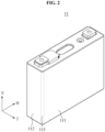
- FIG. 2 is a perspective view illustrating an example of a battery cell 11.
- the battery system 1 supplies a power to or in an object.
- the object includes, for example, a vehicle, a home appliance, or a portable electronic device, however, examples are not limited thereto.
- the battery system 1 is illustrating as including the battery cell 11 having a shape of a rectangle with four rounded edge portions 113 parallel to a height direction V of the battery cell 11, examples also include various battery systems including varied battery cell shapes.
- the battery system 1 includes a plurality of battery cells 11, a plurality of cooling structures 12 and 13, and a plurality of fixers 14.
- the plurality of battery cells 11 supply a power to an object.
- Each of the plurality of battery cells 11 includes a large area portion (e.g., a large surface) 111, a small area portion (e.g., a small surface) 112, and the edge portion 113 between the large area portion 111 and the small area portion 112, noting that the large area portion is larger than the small area portion.
- the edge portion 113 is curved outwardly.
- the plurality of battery cells 11 are arranged so that large area portions 111 face each other or small area portions 112 face each other.
- the plurality of cooling structures 12 and 13 cool the plurality of battery cells 11. Also, the plurality of cooling structures 12 and 13 press the plurality of battery cells 11. When a predetermined pressure is applied to the plurality of battery cells 11, a power supply efficiency of the battery cells 11 may be enhanced.
- the plurality of cooling structures 12 and 13 include a first cooling structure 12 ( Fig. 3 ) and a second cooling structure 13 ( Fig. 13 ).
- the first cooling structure 12 is interposed between a pair of adjacent battery cells 11 so that a flow path 123 of FIG. 3 through which a coolant (e.g., a refrigerant) for cooling the plurality of battery cells 11 flows is formed between large area portions 111 of the battery cells 11.
- the refrigerant includes, for example, a liquid refrigerant, such as oil or water, or a gas refrigerant, such as air.
- the second cooling structure 13 is installed on a large area portion 111 of an outermost battery cell 11 among the plurality of battery cells 11.
- the plurality of fixers 14 press the plurality of battery cells 11 and the plurality of cooling structures 12 and 13.
- the plurality of fixers 14 are installed on a small area portion 112 of an outermost battery cell 11 among the plurality of battery cells 11.
- the plurality of cooling structures 12 and 13 apply a desired pressure to the plurality of battery cells 11, and thus the power supply efficiency of the plurality of battery cells 11 may be advantageously enhanced.
- FIG. 3 is a perspective view illustrating an example of a cooling structure 12
- FIG. 4 is a front view of a cooling structure 12
- FIG. 5 is a plan view of a cooling structure 12.
- the cooling structure 12 includes a plurality of bars 121, a support 122, a plurality of flow paths 123, an upper frame 124, a lower frame 125, and a sealing portion 126.
- the cooling structure 12 with respect to FIGS. 1 through 5 may be a same cooling structure.
- the plurality of bars 121 support and press a battery cell 11.
- the plurality of bars 121 have a length extending in one direction.
- the plurality of bars 121 extend a longitudinal direction H of the battery cell 11.
- the plurality of bars 121 are spaced apart from each other.
- an arrangement direction V of the plurality of bars 121 corresponds to a height direction V of the battery cell 11.
- the plurality of bars 121 are disposed between a pair of adjacent battery cells 11.
- both sides of the plurality of bars 121 are disposed between large area portions 111 of a pair of adjacent battery cells 11.
- both sides of the plurality of bars 121 contact the large area portions 111 of the adjacent battery cells 11.
- the support 122 supports the plurality of bars 121.
- the support 122 includes an inflow support 1221 that is disposed on an inlet side and to which a refrigerant for cooling the battery cell 11 flows, and an outflow support 1222 that is disposed on an outlet side and from which the refrigerant flows.
- the inflow support 1221 extends in the arrangement direction V of the plurality of bars 121 and connects first end portions of the plurality of bars 121.
- the outflow support 1222 extends in the arrangement direction V of the plurality of bars 121 and connects second end portions opposite the first end portions of the plurality of bars 121.
- the inflow support 1221 includes an inflow flange F1 that extends in a plane perpendicular to the longitudinal direction H of the plurality of bars 121 on the first end portions of the plurality of bars 121.
- the outflow support 1222 includes an outflow flange F2 that extends in the plane perpendicular to the longitudinal direction H of the plurality of bars 121 on the second end portions of the plurality of bars 121.
- Each of the inflow flange F1 and the outflow flange F2 is disposed to partially cover small area portions 112 of a pair of adjacent battery cells 11 and a gap is formed between the adjacent battery cells 11.
- the plurality of flow paths 123 guide flow of refrigerants in direct contact with battery cells 11.
- the plurality of flow paths 123 are defined by surfaces of battery cells 11 and a pair of adjacent bars 121.
- the plurality of flow paths 123 are defined by large area portions 111 among surfaces of battery cells 11, and by a top surface and a bottom surface that do not press a surface of a battery cell 11 among surfaces of a pair of adjacent bars 121. Since the refrigerant is in direct contact with a battery cell 11 as described above, heat is able to be directly exchanged even though a heat transfer member, for example, a thermal pad, a pipe or a cooling fin, is not interposed between battery cells 11 and a flowing refrigerant, to enhance a cooling efficiency.
- a heat transfer member for example, a thermal pad, a pipe or a cooling fin
- a problem of a distribution of the refrigerant being propelled downward due to an influence of the gravity may be reduced, and thus a temperature variation may be advantageously reduced in battery cells 11, which in turn may greatly improve a lifespan of the battery cells 11.
- the plurality of bars 121 are spaced apart from each other at suitable intervals. Based on the above structure, a deformation (for example, a swelling) of a battery cell 11, or a deformation of the plurality of flow paths 123 due to an external force, may be advantageously prevented while securing the plurality of flow paths 123 through which refrigerants flow in direct contact with battery cells 11. Also, based on the above structure, a flow rate of a refrigerant flowing through the plurality of flow paths 123 may be advantageously determined or controlled by design.
- the plurality of bars 121 are designed to be spaced apart from each other at the same intervals, and thus the plurality of flow paths 123 have the same cross-sectional areas.
- the plurality of bars 121 are spaced apart from each other at different intervals so that a portion of a battery cell 11 with a greatest increase in a temperature is intensively cooled. For example, when a central portion of a battery cell 11 has a highest operating temperature, a gap between a pair of adjacent bars 121 in the central portion of the battery cell 11 is greater than a gap between a pair of adjacent bars 121 in an upper portion or a lower portion of the battery cell 11. Based on the above structure, the central portion of the battery cell may be more intensively cooled than the upper or the lower portion. Accordingly, cooling intensity is in proportion to battery temperature, and thus coolant may be allocated efficiently, and thus a cooling efficiency may be advantageously enhanced.
- the plurality of flow paths 123 are located in only a central portion of a battery cell 11.
- the plurality of bars 121 are spaced apart from each other in only the central portion of the battery cell 11, and a refrigerant flow path is not formed in the other portions in a space of a pair of adjacent battery cells 11.
- the total cross-sectional area of the plurality of flow paths 123 is reduced relative to when the plurality of flow paths 123 are located along an entire portion of the battery cell 11, and thus a cooling efficiency of a predetermined portion is advantageously enhanced.
- the upper frame 124 is disposed above the plurality of bars 121 and connects the inflow support 1221 and the outflow support 1222.
- the upper frame 124 extends in the longitudinal direction H of the plurality of bars 121.
- the upper frame 124 includes a first upper frame connector 1241 that connects the upper frame 124 and the inflow support 1221, and a second upper frame connector 1242 that connects the upper frame 124 and the outflow support 1222.
- the first upper frame connector 1241 is formed on a first end portion of the upper frame 124
- the second upper frame connector 1242 is formed on a second end portion of the upper frame 124 opposite the first end portion.
- the first upper frame connector 1241 and the second upper frame connector 1242 are curved inwardly toward a battery cell 11 to contact an upper portion of the battery cell 11.
- the lower frame 125 is disposed below the plurality of bars 121, and connects the inflow support 1221 and the outflow support 1222.
- the lower frame 125 extends in the longitudinal direction H of the plurality of bars 121.
- the lower frame 125 includes a first lower frame connector 1251 that connects the lower frame 125 and the inflow support 1221, and a second lower frame connector 1252 that connects the lower frame 125 and the outflow support 1222.
- the first lower frame connector 1251 is formed on a first end portion of the lower frame 125
- the second lower frame connector 1252 is formed on a second end portion of the lower frame 125 opposite the first end portion.
- the first lower frame connector 1251 and the second lower frame connector 1252 are curved inwardly toward a battery cell 11 to contact a lower portion of the battery cell 11.
- Components having the same configuration as the first upper frame connector 1241, the second upper frame connector 1242, the first lower frame connector 1251 and the second lower frame connector 1252 may also be formed on one side of a cooling structure 12 facing another battery cell 11.
- the upper frame 124 and the lower frame 125 are formed of more flexible and/or compressible materials than those of the plurality of bars 121, and a thickness of each of the upper frame 124 and the lower frame 125 in the direction V is greater than those of the plurality of bars 121. Based on the above structure, sealability of the cooling structure 12 may be advantageously enhanced. Also, even if a battery cell 11 is deformed beyond an expected range, leakage of refrigerants from the plurality of flow paths 123 may be advantageously prevented by tolerating the above deformation to a predetermined level.
- the plurality of bars 121, the support 122, the upper frame 124 and the lower frame 125 are formed of insulative materials.
- An insulative material includes, for example, any material suitable for an electrical isolation between a pair of adjacent battery cells 11.
- the insulative material may include plastic.
- the sealing portion 126 encloses the plurality of bars 121 and the plurality of flow paths 123.
- the sealing portion 126 forms a heat exchange space between a pair of adjacent battery cells 11 and the cooling structure 12.
- the heat exchange space is defined by the plurality of bars 121, the support 122, the plurality of flow paths 123, the upper frame 124, the lower frame 125, the sealing portion 126, and surfaces of the pair of adjacent battery cells 11.
- the heat exchange space is closed from the outside except for an inflow passage P1 of FIG. 6 and an outflow passage P2 of FIG. 9 .
- Sealing portions 126 are installed on one side of a cooling structure 12 facing a large area portion 111 of one of a pair of adjacent battery cells 11, and another side of the cooling structure 12 facing a large area portion 111 of the other of the pair of adjacent battery cells 11, respectively.
- the sealing portion 126 includes longitudinal direction members 1261a and 1261b, arrangement direction members 1262a and 1262b of FIG. 12 , and connection members 1263a, 1264a, 1264b, 1265a, 1265b, 1266a and 1266b of FIG. 12 .
- the longitudinal direction members 1261a and 1261b extend in the longitudinal direction H of the plurality of bars 121 and contact a first surface of a battery cell 11.
- the first surface is a large area portion 111 of the battery cell 11.
- the longitudinal direction members 1261a and 1261b include an upper longitudinal direction member 1261a installed in the upper frame 124, and a lower longitudinal direction member 1261b installed in the lower frame 125.
- the arrangement direction members 1262a and 1262b extend in the arrangement direction V of the plurality of bars 121 and contact a second surface of the battery cell 11.
- the second surface is a small area portion 112 of the battery cell 11.
- the arrangement direction members 1262a and 1262b include an inflow arrangement direction member 1262a of FIG. 12 installed in the inflow support 1221, and an outflow arrangement direction member 1262b of FIG. 3 installed in the outflow support 1222.
- connection members 1263a, 1264a, 1264b, 1265a, 1265b, 1266a and 1266b connect the longitudinal direction members 1261a and 1261b and the arrangement direction members 1262a and 1262b, and contact an edge portion between the first surface (e.g., a large area portion 111) and the second surface (e.g., the small area portion 112) of the battery cell 11.
- the connection members 1263a, 1264a, 1264b, 1265a, 1265b, 1266a and 1266b include upper connection members 1263a, 1264a, 1265a and 1266a, and lower connection members 1264b, 1265b and 1266b.
- the upper connection members 1263a, 1264a, 1265a and 1266a include the first upper connection member 1263a that is connected to the inflow arrangement direction member 1262a and that is formed in the inflow support 1221, the second upper connection member 1264a that connects the first upper connection member 1263a and the upper longitudinal direction member 1261a and that is formed in the first upper frame connector 1241, the third upper connection member 1265a that is connected to the outflow arrangement direction member 1262b and that is formed in the outflow support 1222, and the fourth upper connection member 1266a that connects the third upper connection member 1265a and the upper longitudinal direction member 1261a and that is formed in the second upper frame connector 1242.
- the lower connection members 1264b, 1265b and 1266b include the first lower connection member that is connected to the inflow arrangement direction member 1262a and that is formed in the inflow support 1221, the second lower connection member 1264b that connects the first lower connection member and the lower longitudinal direction member 1261b and that is formed in the first lower frame connector 1251, the third lower connection member 1265b that is connected to the outflow arrangement direction member 1262b and that is formed in the outflow support 1222, and the fourth lower connection member 1266b that connects the third lower connection member 1265b and the lower longitudinal direction member 1261b and that is formed in the second lower frame connector 1252.
- the heat exchange space determined by the plurality of bars 121, the support 122, the plurality of flow paths 123, the upper frame 124, the lower frame 125, the sealing portion 126 and the surfaces of the pair of battery cells 11 has an advantageous three-dimensional (3D) structure of sealing the heat exchange space from the outside.
- FIG. 6 illustrates an example of the inflow support 1221
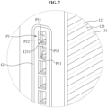
- FIG. 7 is a perspective view illustrating an example of a portion of an inflow support (e.g., a portion of the inflow support 1221 of FIG. 6 ).
- the inflow support 1221 includes the inflow flange F1, the inflow passage P1, and a first sealing member G1.
- the inflow flange F1 extends in the plane perpendicular to the longitudinal direction H of the plurality of bars 121.
- the inflow passage P1 guides inflow of a refrigerant to the plurality of flow paths 123.
- the inflow passage P1 includes a plurality of inflow ports P11, a concave portion P12, and a first partition P13.
- the plurality of inflow ports P11 fluidly communicate with the plurality of flow paths 123.
- the plurality of inflow ports P11 are spaced apart from each other in a height direction V of the inflow support 1221 (wherein, e.g., a height direction V of the inflow support 1221 corresponds to an arrangement direction V of the plurality of bars 121 and a height direction V of the battery cell 11).
- flow rates of refrigerants flowing through the plurality of flow paths 123 may be configured to be individually controlled. For example, a flow rate of a refrigerant flowing through a flow path 123 disposed in a central portion of the battery cell 11 of FIG. 2 among the plurality of flow paths 123 is controlled to increase, and a flow rate of a refrigerant flowing through a flow path 123 disposed in an upper portion or lower portion of the battery cell 11 among the plurality of flow paths 123 is controlled to decrease.
- the concave portion P12 is engaged with a protruding portion P22 (e.g., as shown in FIG. 10 ) of the outflow passage P2 of the outflow support 1222.
- the concave portion P12 is recessed inwardly toward the inflow support 1221 and is formed in a circumferential direction of the inflow port P11.
- the concave portion P12 has a stepped structure in which steps are formed based on a flow direction of a refrigerant passing through the inflow port P1.
- a first end portion 1211 of each of the plurality of bars 121 is connected between a pair of adjacent inflow ports P11.
- the first end portion 1211 forms an upper wall or a lower wall of the inflow port P11 and is connected to the concave portion P12.
- the first partition P13 partitions the inflow passage P1 to form a plurality of inflow ports P11.
- the first partition P13 is located between a pair of adjacent inflow ports P11.
- the first partition P13 overlaps a bar 121 in a longitudinal direction H of the bar 121.
- the first partition P13 and a first end portion 1211 of the bar 121 are fixed to each other.
- a stepped structure of the concave portion P12 is formed between the first partition P13 and a first end portion 1211 of each of the plurality of bars 121.
- the first sealing member G1 seals the inflow passage P1 from the outside.
- the first sealing member G1 encloses the inflow passage P1 to form a closed loop.
- FIG. 8 illustrates an example of an inflow support 2221.
- the inflow support 2221 includes an inflow flange F1, an inflow passage P1' and a first sealing member G1.
- the inflow passage P1' includes a single inflow port P11' and a concave portion P12'.
- the inflow port P11' has a shape of a slot extending in a height direction of the inflow support 2221.
- the concave portion P12' is recessed inwardly toward the inflow support 2221 and is formed in a circumferential direction of the inflow port P11'.
- the inflow port P11' shares a plurality of flow paths (not shown) and fluidly communicates with the plurality of flow paths.
- an inflow support may include at least one inflow port that shares a portion of a plurality of flow paths.
- the inflow support may have a manifold structure that guides flow of a refrigerant from one inflow port to the plurality of flow paths.
- a plurality of inflow ports may share a pair of adjacent flow paths. In an example, "10" flow paths are provided and "5" inflow ports are provided.
- FIG. 9 illustrates an example of the outflow support 1222
- FIG. 10 illustrates an example of a portion of an outflow support (e.g., a portion of the outflow support 1222 of FIG. 9 ).
- the outflow support 1222 includes the outflow flange F2, the outflow passage P2, and a second sealing member G2.
- the outflow flange F2 extends in the plane perpendicular to the longitudinal direction H of the plurality of bars 121.
- the outflow passage P2 guides outflow of a refrigerant from the plurality of flow paths 123.
- the outflow passage P2 includes a plurality of outflow ports P21, the protruding portion P22, and a second partition P23.
- the plurality of outflow ports P21 fluidly communicate with the plurality of flow paths 123.
- the plurality of outflow ports P21 are spaced apart from each other in a height direction of the outflow support 1222.
- the protruding portion P22 is engaged with the concave portion P12 of the inflow passage P1 of the inflow support 1221.
- the protruding portion P22 protrudes outwardly from the outflow support 1222 and is formed in a circumferential direction of the outflow port P21.
- one cooling structure 12 and another cooling structure 12 are coupled as shown in FIG. 1 .
- a degree of coupling between the cooling structures 12 is enhanced by an engagement structure between the concave portion P12 and the protruding portion P22.
- the inflow passage P1 of FIG. 7 of the inflow support 1221 of FIG. 6 may include the protruding portion P22, and the outflow passage P2 of the outflow support 1222 may include the concave portion P12 of FIG. 7 .
- a second end portion 1212, see Fig. 10 , of each of the plurality of bars 121 forms an upper wall or a lower wall of a pair of adjacent outflow ports P21 and is connected to the protruding portion P22.
- the second partition P23 partitions the outflow passage P2 to form the plurality of outflow ports P21.
- the second partition P23 is located between a pair of adjacent outflow ports P21.
- the second partition P23 overlaps a bar 121 based on a longitudinal direction of the bar 12.
- the second partition P23 and a second end portion 1212 of the bar 121 are fixed to each other.
- the second sealing member G2 seals the outflow passage P2 from the outside.
- the second sealing member G2 encloses the outflow passage P2 to form a closed loop.
- FIG. 11 illustrates an example of an outflow support 2222.
- the outflow support 2222 includes an outflow flange F2, an outflow passage P2', and a second sealing member G2.
- the outflow passage P2' includes a single outflow port P21' and a protruding portion P22'.
- the outflow port P21' has a shape of a slot extending in a height direction of the outflow support 2222.
- the protruding portion P22' protrudes outwardly from the outflow support 2222 and is formed in a circumferential direction of the outflow port P21'.
- the outflow port P21' shares a plurality of flow paths (not shown) and fluidly communicates with the plurality of flow paths.
- an outflow support may include at least one outflow port that shares a portion of a plurality of flow paths.
- the outflow support may have a manifold structure that guides flow of a refrigerant from the plurality of flow paths to one outflow port.
- a plurality of outflow ports may share a pair of adjacent flow paths. In an example, "10" flow paths are provided and "5" outflow ports are provided.
- FIG. 12 illustrates an example of an inflow support 1221 connected to the plurality of bars 121 and the upper frame 124.
- the plurality of bars 121 include connectors 1213 that connect the plurality of bars 121 to the support 122. Based on the above structure, structural rigidness of the cooling structure 12 is enhanced. Thus, a plurality of thin bars 121 can be manufactured, and an amount of a refrigerant flowing in the plurality of flow paths 123 can advantageously be increased, which is advantageous in terms of the flow rate of the refrigerant.
- the connector 1213 is curved inwardly to contact the edge portion 113 of the battery cell 11 of FIG. 2 .
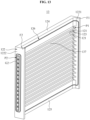
- FIG. 13 is a perspective view illustrating an example of a cooling structure 13 disposed on an outermost side of a battery system.
- the second cooling structure 13 includes the plurality of bars 121, the support 122 including the inflow support 1221 and the outflow support 1222, the plurality of flow paths 123, the upper frame 124, the lower frame 125 and the sealing portion 126 that are described above with reference to FIGS. 3 through 7 , 9 , 10 and 12 .
- the inflow support 1221 includes an inflow flange F1, an inflow passage P1 and a first sealing member (not shown)
- the outflow support 1222 includes an outflow flange F2, an outflow passage P2 and a second sealing member G2.
- the inflow flange F1 and the outflow flange F2 extend only in one direction with respect to the plurality of bars 121, unlike the first cooling structure 12 interposed between adjacent battery cells 11. Also, the sealing portion 126 is formed only on a side of the first cooling structure 12 facing the large area portion 111 of the battery cell 11 of FIG. 2 supported and pressed by the cooling structure 12.
- the second cooling structure 13 disposed on the outermost side of the battery system 1 of FIG. 1 further includes a closing portion 137.
- the closing portion 137 defines the plurality of flow paths 123, together with a large area portion 111 of the battery cell 11 supported and pressed by the second cooling structure 13, and a pair of adjacent bars 121.
- the closing portion 137 is formed of a material with a low thermal conductivity coefficient to form an enclosed heat exchange space. To enhance a structural stability, the plurality of bars 121 are fixed to the closing portion 137.
- FIG. 14 is a perspective view illustrating an example of a further cooling structure 32.
- the cooling structure 32 includes a plurality of bars 321, a support 322 including an inflow support 3221 and an outflow support 3222, a plurality of flow paths 323, an upper frame 324, a lower frame 325, and a sealing portion 326.
- the inflow support 3221 includes a plurality of inflow passages P1 that fluidly communicate with the plurality of flow paths 323, and a first sealing member G1 that encloses the plurality of inflow passages P1.
- the outflow support 3222 includes a plurality of outflow passages (not shown) that fluidly communicate with the plurality of flow paths 323, and a second sealing member (not shown) that encloses the plurality of outflow passages.
- a thickness of the inflow support 3221 and a thickness of the outflow support 3222 are equal to a thickness of the upper frame 324 and a thickness of the lower frame 325.
- the further cooling structure 32 has a shape of a rectangular parallelepiped.
- a two-dimensional (2D) sealing structure is formed by an upper longitudinal direction member 3261a, a lower longitudinal direction member 3261b, an inflow arrangement direction member 3262a and an outflow arrangement direction member 3262b of the sealing portion 326 that encloses the plurality of bars 321 and the plurality of flow paths 323.
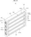
- FIG. 15 is a perspective view illustrating an example of another cooling structure 42.
- the cooling structure 42 includes a plurality of bars 421, a support 422 including an inflow support 4221 and an outflow support 4222, a plurality of flow paths 423, an upper frame 424, a lower frame 425, and a sealing portion 426.
- the inflow support 4221 includes a plurality of inflow passages P1 that fluidly communicate with the plurality of flow paths 423, and a first sealing member G1 that encloses the plurality of inflow passages P1.
- the outflow support 4222 includes a plurality of outflow passages (not shown) that fluidly communicate with the plurality of flow paths 323, and a second sealing member (not shown) that encloses the plurality of outflow passages.
- a thickness of the inflow support 4221 and a thickness of the outflow support 4222 are equal to a thickness of the upper frame 424 and a thickness of the lower frame 425.
- the sealing portion 426 encloses the plurality of bars 421 and the plurality of flow paths 423.
- the sealing portion 426 individually encloses the plurality of flow paths 423, to form a plurality of heat exchange spaces, together with a pair of adjacent bars 421 and surfaces of a pair of adjacent battery cells (not shown).
- the sealing portion 426 includes an upper longitudinal direction member 4261a, a lower longitudinal direction member 4261b, an inflow arrangement direction member 4262a and an outflow arrangement direction member 4262b that extend along all boundaries of the plurality of bars 421 and the plurality of flow paths 423.
- the sealing portion 426 further includes a plurality of intermediate longitudinal direction members 4261c that are parallel to the upper longitudinal direction member 4261a and the lower longitudinal direction member 4261b, that are perpendicular to the inflow arrangement direction member 4262a and the outflow arrangement direction member 4262b, and that respectively extend along the plurality of bars 421.
Landscapes
- Chemical & Material Sciences (AREA)
- Chemical Kinetics & Catalysis (AREA)
- Electrochemistry (AREA)
- General Chemical & Material Sciences (AREA)
- Engineering & Computer Science (AREA)
- Manufacturing & Machinery (AREA)
- Secondary Cells (AREA)
- Battery Mounting, Suspending (AREA)
Description
- The following description relates to a structure and system with battery cooling.
- Technologies of cooling battery cells that supply electric power to be used in, for example, vehicles, mobile phones, and the like, have been developed. Methods of cooling a battery cell include a direct cooling method and an indirect cooling method. The direct cooling method refers to a heat transfer method in which a refrigerant directly contacts an object to be cooled, and the indirect cooling method refers to a heat transfer between a refrigerant and an object to be cooled, using at least one medium layer between the refrigerant and the object.
-
DE 10 2015 223 408 A1 discloses a cooling structure with plurality of energy storage devices and distance members therebetween. The cooling structures comprise two parts, namely an intermediate cooling structure and a lateral cooling structure. The corresponding cooling structures have a particular wall member, which comprsises alternating grooves, wherein one groove is directed to one battery cell and the next groove is directed to the neigboring battery cell. -
DE 10 2015 220 856 A1 discloses cooling structure for a number of battery cells comprising a number of ribs, which are spaced apart from each other, wherein at least some of the ribs are configured to extend along a first surface of a battery cell. Between the corresponding ribs, a number of flow paths are defined. - This Summary is provided to introduce a selection of concepts in a simplified form that are further described below in the Detailed Description. This Summary is not intended to identify key features or essential features of the claimed subject matter, nor is it intended to be used as an aid in determining the scope of the claimed subject matter.
- In one general aspect, a cooling structure includes: a plurality of bars spaced apart from each other and configured to extend along a first surface of a battery cell; a support configured to support the plurality of bars; and a plurality of flow paths defined by the first surface of the battery cell and a pair of adjacent bars of the plurality of bars, the plurality of flow paths being configured to guide flow of a coolant in contact with the first surface of the battery cell.
- The cooling structure further includes: a sealing portion configured to enclose the plurality of bars and the plurality of flow paths.
- The sealing portion includes: a longitudinal direction member extending in a longitudinal direction of the plurality of bars and configured to contact the first surface of the battery cell; an arrangement direction member extending in an arrangement direction of the plurality of bars and configured to contact a second surface of the battery cell; and a connection
member configured to connect the longitudinal direction member and the arrangement direction member and to contact an edge portion between the first surface and the second surface of the battery cell. - The support may include: an inflow support comprising an inflow passage configured to guide inflow of the coolant to the plurality of flow paths; and an outflow support comprising an outflow passage configured to guide outflow of the coolant from the plurality of flow paths.
- The inflow passage may include a plurality of inflow ports, the outflow passage comprises a plurality of outflow ports, one end of each of the plurality of bars is connected between a pair of adjacent inflow ports, and another end of each of the plurality of bars is connected between a pair of adjacent outflow ports.
- The inflow support further may include a first sealing member configured to enclose the inflow passage, and the outflow support further comprises a second sealing member configured to enclose the outflow passage.
- The first sealing member may be configured to enclose the inflow passage to form a closed loop, and the second sealing member is configured to enclose the outflow passage to form another closed loop.
- The support may include a flange extending in a plane perpendicular to a longitudinal direction of the plurality of bars.
- The cooling structure may include: a plurality of connectors configured to connect the support to an end portion of each of the plurality of bars.
- The connector may be curved inwardly to be configured to contact an edge portion the battery cell.
- The support and the plurality of bars may be formed of insulative materials.
- The cooling structure may include: an upper frame disposed above the plurality of bars in an arrangement direction of the plurality of bars; and a lower frame disposed below the plurality of bars in the arrangement direction of the plurality of bars.
- A thickness of the upper frame and a thickness of the lower frame may be greater than a thickness of the plurality of bars in the arrangement direction of the plurality of bars, and the upper frame and the lower frame may be formed of a more flexible material than a material of the plurality of bars.
- The first surface of the battery cell may be larger than plural other surfaces of the battery cell.
- The plurality of flow paths may be in contact with only a central portion of the battery cell in an arrangement direction of the plurality of bars.
- The plurality of bars may be arranged in a vertical direction of the battery cell, and a gap between a pair of adjacent bars in a central portion of the battery cell in the vertical direction is greater than a gap between a pair of adjacent bars in an upper portion or a lower portion of the battery cell in the vertical direction.
- The cooling structure may include: the battery cell and a second battery cell; and the plurality of bars, the support, and the plurality of flow paths may be interposed between the battery cell and the second battery cell.
- In another general aspect, a battery system includes: a first battery cell; a second battery cell; and a first cooling structure interposed between the first battery cell and the second battery cell, and comprising: a plurality of first bars spaced apart from each other and configured to extend along a surface of the first battery cell and a surface of the second battery cell; and a plurality of first flow paths defined by the surface of the first battery cell, the surface of the second battery cell, and a pair of adjacent first bars of the plurality of first bars, the plurality of first flow paths being configured to guide flow of a coolant in contact with the surface of the first battery cell and the surface of the second battery cell.
- The first cooling structure includes a first sealing portion disposed at one side of the first cooling structure facing the surface of the first battery cell and configured to enclose the plurality of first bars and the plurality of first flow paths; and a second sealing portion disposed at another side of the first cooling structure facing the surface of the second battery cell and configured to enclose the plurality of first bars and the plurality of first flow paths.
- The battery system may include: a second cooling structure disposed to face the first cooling structure based on the second battery cell, and comprising: a plurality of second bars spaced apart from each other and configured to extend along another surface of the second battery cell; a plurality of second flow paths configured to guide flow of the coolant in direct contact with the other surface of the second battery cell; and a closing portion configured to define the plurality of second flow paths together with the other surface of the second battery cell and a pair of adjacent second bars.
- The battery system may include: a fixer configured to press the first battery cell, the second battery cell, and the first cooling structure in a direction perpendicular to a direction of the flow of the coolant.
- In another general aspect, a battery system includes: a first battery cell; a first cooling structure configured to cool the first battery cell and comprising: a plurality of first bars spaced apart from each other and configured to extend along a surface the first battery cell, a plurality of first flow paths defined by the surface of the first battery cell and a pair of adjacent first bars, and configured to guide flow of a coolant in contact with the surface of the first battery cell, and a first support configured to support the plurality of first bars; a second battery cell; and a second cooling structure configured to cool the second battery cell and comprising: a plurality of second bars spaced apart from each other and configured to extend along a surface of the second battery cell, a plurality of second flow paths defined by the surface of the second battery cell and a pair of adjacent second bars, and configured to guide flow of the coolant in contact with the surface of the second battery cell, and a second support configured to support the plurality of second bars, and coupled with the first support so that the plurality of first flow paths and the plurality of second flow paths fluidly communicate with each other.
- Each of the first support and the second support may include: an inflow support comprising an inflow passage configured to respectively guide inflow of the coolant to the plurality of first flow paths or the plurality of second flow paths; and an outflow support comprising an outflow passage configured to respectively guide outflow of the coolant from the plurality of first flow paths or the plurality of second flow paths, wherein the outflow passage of the outflow support of the first support is engaged with the inflow passage of the inflow support of the second support.
- One of the inflow support and the outflow support may include a concave portion recessed inwardly, and the other one of the inflow support and the outflow support comprises a protruding portion protruding outwardly and configured to engaged with the concave portion.
- The first support and the second support may each include a flange configured to partition the first battery cell and the second battery cell and extending in a plane perpendicular to a longitudinal direction of each of the plurality of first bars and the plurality of second bars.
- In another general aspect, a cooling system includes: a first cooling structure configured to be disposed at a first surface of a battery and comprising a first bar and a second bar each configured to extend in a first direction along the surface to form a first coolant flow path; and a second cooling structure configured to be disposed at a second surface of the battery, opposite the first surface, and comprising a third and a fourth bar configured to extend in the first direction along the second surface to form a second coolant flow path.
- The first cooling structure may be separated from the second cooling structure in a second direction perpendicular to the first direction to allow an expansion of the battery in the second direction.
- Either one or both of the first and the second cooling structures may be configured to maintain a cross-section of the respective first or second coolant path in response to an expansion of the battery in the second direction.
- The first coolant flow path may be bound by a lower surface of the first bar, an upper surface of the second bar, the first surface of the battery, and either a surface of another battery or a closing portion of the first cooling structure, and the second coolant flow path may be bound by a lower surface of the third bar, an upper surface of the fourth bar, the second surface of the battery, and either a surface of an additional battery or a closing portion of the second cooling structure.
- Other features and aspects will be apparent from the following detailed description, the drawings, and the claims.
-
-
FIG. 1 is a perspective view illustrating an example of a battery system. -
FIG. 2 is a perspective view illustrating an example of a battery cell. -
FIG. 3 is a perspective view illustrating an example of a cooling structure. -
FIG. 4 is a front view illustrating an example of a cooling structure. -
FIG. 5 is a plan view illustrating an example of a cooling structure. -
FIG. 6 illustrates an example of an inflow support. -
FIG. 7 is a perspective view illustrating an example of a portion of an inflow support. -
FIG. 8 illustrates an example of an inflow support. -
FIG. 9 illustrates an example of an outflow support. -
FIG. 10 is a perspective view illustrating an example of a portion of an outflow support. -
FIG. 11 illustrates an example of an outflow support. -
FIG. 12 illustrates an example of an inflow support connected to a plurality of bars and an upper frame. -
FIG. 13 is a perspective view illustrating an example of a cooling structure disposed on an outermost side of a battery system. -
FIG. 14 is a perspective view illustrating an example of a cooling structure. -
FIG. 15 is a perspective view illustrating an example of a cooling structure. - Throughout the drawings and the detailed description, unless otherwise described or provided, the same drawing reference numerals will be understood to refer to the same elements, features, and structures. The drawings may not be to scale, and the relative size, proportions, and depiction of elements in the drawings may be exaggerated for clarity, illustration, and convenience.
- The following detailed description is provided to assist the reader in gaining a comprehensive understanding of the methods, apparatuses, and/or systems described herein. However, various changes, modifications, and equivalents of the methods, apparatuses, and/or systems described herein will be apparent after an understanding of the disclosure of this application. For example, the sequences of operations described herein are merely examples, and are not limited to those set forth herein, but may be changed as will be apparent after an understanding of the disclosure of this application, with the exception of operations necessarily occurring in a certain order. Also, descriptions of features that are known in the art may be omitted for increased clarity and conciseness.
- The features described herein may be embodied in different forms, and are not to be construed as being limited to the examples described herein. Rather, the examples described herein have been provided merely to illustrate some of the many possible ways of implementing the methods, apparatuses, and/or systems described herein that will be apparent after an understanding of the disclosure of this application.
- The following structural or functional descriptions of examples disclosed in the present disclosure are merely intended for the purpose of describing the examples and the examples may be implemented in various forms. The examples are not meant to be limited, but it is intended that various modifications, equivalents, and alternatives are also covered within the scope of the claims.
- Hereinafter, examples will be described with reference to the accompanying drawings. In the following description, the same elements will be designated by the same reference numerals although they are shown in different drawings. Also, in the following description of examples, a detailed description of known functions and configurations incorporated herein will be omitted when it is deemed that such description will cause ambiguous interpretation of the examples.
- Also, to describe components according to examples, the terms first, second, A, B, (a), (b), etc. may be used herein. These terms are merely used to distinguish one component from another, but not to define an essence, order or sequence of the components. It should be noted that if it is described in the specification that one component is "connected", "coupled", or "joined" to another component, a third component may be "connected," "coupled," and "joined" between the first and second components, although the first component may be directly connected, coupled or joined to the second component.
- A component included in one example and a component having a common function will be described using the same names in other examples. Description of one example may be applied to other examples, and overlapping detailed descriptions thereof will be omitted, unless mentioned otherwise.
-
FIG. 1 is a perspective view illustrating an example of abattery system 1, andFIG. 2 is a perspective view illustrating an example of abattery cell 11. - Referring to
FIGS. 1 and2 , thebattery system 1 supplies a power to or in an object. The object includes, for example, a vehicle, a home appliance, or a portable electronic device, however, examples are not limited thereto. Also, although thebattery system 1 is illustrating as including thebattery cell 11 having a shape of a rectangle with fourrounded edge portions 113 parallel to a height direction V of thebattery cell 11, examples also include various battery systems including varied battery cell shapes. - The
battery system 1 includes a plurality ofbattery cells 11, a plurality of coolingstructures fixers 14. - The plurality of
battery cells 11 supply a power to an object. Each of the plurality ofbattery cells 11 includes a large area portion (e.g., a large surface) 111, a small area portion (e.g., a small surface) 112, and theedge portion 113 between thelarge area portion 111 and thesmall area portion 112, noting that the large area portion is larger than the small area portion. For example, theedge portion 113 is curved outwardly. The plurality ofbattery cells 11 are arranged so thatlarge area portions 111 face each other orsmall area portions 112 face each other. - The plurality of cooling
structures battery cells 11. Also, the plurality of coolingstructures battery cells 11. When a predetermined pressure is applied to the plurality ofbattery cells 11, a power supply efficiency of thebattery cells 11 may be enhanced. - The plurality of cooling
structures Fig. 3 ) and a second cooling structure 13 (Fig. 13 ). Thefirst cooling structure 12 is interposed between a pair ofadjacent battery cells 11 so that aflow path 123 ofFIG. 3 through which a coolant (e.g., a refrigerant) for cooling the plurality ofbattery cells 11 flows is formed betweenlarge area portions 111 of thebattery cells 11. The refrigerant includes, for example, a liquid refrigerant, such as oil or water, or a gas refrigerant, such as air. Thesecond cooling structure 13 is installed on alarge area portion 111 of anoutermost battery cell 11 among the plurality ofbattery cells 11. - The plurality of
fixers 14 press the plurality ofbattery cells 11 and the plurality of coolingstructures fixers 14 are installed on asmall area portion 112 of anoutermost battery cell 11 among the plurality ofbattery cells 11. By the above structure, the plurality of coolingstructures battery cells 11, and thus the power supply efficiency of the plurality ofbattery cells 11 may be advantageously enhanced. -
FIG. 3 is a perspective view illustrating an example of acooling structure 12,FIG. 4 is a front view of acooling structure 12, andFIG. 5 is a plan view of acooling structure 12. - Referring to
FIGS. 1 through 5 , the coolingstructure 12 includes a plurality ofbars 121, asupport 122, a plurality offlow paths 123, anupper frame 124, alower frame 125, and a sealingportion 126. As a non-limiting example, the coolingstructure 12 with respect toFIGS. 1 through 5 may be a same cooling structure. - The plurality of
bars 121 support and press abattery cell 11. The plurality ofbars 121 have a length extending in one direction. For example, the plurality ofbars 121 extend a longitudinal direction H of thebattery cell 11. The plurality ofbars 121 are spaced apart from each other. For example, an arrangement direction V of the plurality ofbars 121 corresponds to a height direction V of thebattery cell 11. The plurality ofbars 121 are disposed between a pair ofadjacent battery cells 11. For example, both sides of the plurality ofbars 121 are disposed betweenlarge area portions 111 of a pair ofadjacent battery cells 11. Also, both sides of the plurality ofbars 121 contact thelarge area portions 111 of theadjacent battery cells 11. - The
support 122 supports the plurality ofbars 121. Thesupport 122 includes aninflow support 1221 that is disposed on an inlet side and to which a refrigerant for cooling thebattery cell 11 flows, and anoutflow support 1222 that is disposed on an outlet side and from which the refrigerant flows. Theinflow support 1221 extends in the arrangement direction V of the plurality ofbars 121 and connects first end portions of the plurality ofbars 121. Theoutflow support 1222 extends in the arrangement direction V of the plurality ofbars 121 and connects second end portions opposite the first end portions of the plurality ofbars 121. - The
inflow support 1221 includes an inflow flange F1 that extends in a plane perpendicular to the longitudinal direction H of the plurality ofbars 121 on the first end portions of the plurality ofbars 121. Theoutflow support 1222 includes an outflow flange F2 that extends in the plane perpendicular to the longitudinal direction H of the plurality ofbars 121 on the second end portions of the plurality ofbars 121. Each of the inflow flange F1 and the outflow flange F2 is disposed to partially coversmall area portions 112 of a pair ofadjacent battery cells 11 and a gap is formed between theadjacent battery cells 11. By the above structure,adjacent battery cells 11 are electrically isolated. Also, although a thermal abuse or thermal runaway occurs inarbitrary battery cell 11, heat of the thermal runaway is prevented from being transferred from thebattery cell 11 to a neighboringbattery cell 11. - The plurality of
flow paths 123 guide flow of refrigerants in direct contact withbattery cells 11. The plurality offlow paths 123 are defined by surfaces ofbattery cells 11 and a pair ofadjacent bars 121. For example, the plurality offlow paths 123 are defined bylarge area portions 111 among surfaces ofbattery cells 11, and by a top surface and a bottom surface that do not press a surface of abattery cell 11 among surfaces of a pair ofadjacent bars 121. Since the refrigerant is in direct contact with abattery cell 11 as described above, heat is able to be directly exchanged even though a heat transfer member, for example, a thermal pad, a pipe or a cooling fin, is not interposed betweenbattery cells 11 and a flowing refrigerant, to enhance a cooling efficiency. Also, by the plurality offlow paths 123, a problem of a distribution of the refrigerant being propelled downward due to an influence of the gravity may be reduced, and thus a temperature variation may be advantageously reduced inbattery cells 11, which in turn may greatly improve a lifespan of thebattery cells 11. - The plurality of
bars 121 are spaced apart from each other at suitable intervals. Based on the above structure, a deformation (for example, a swelling) of abattery cell 11, or a deformation of the plurality offlow paths 123 due to an external force, may be advantageously prevented while securing the plurality offlow paths 123 through which refrigerants flow in direct contact withbattery cells 11. Also, based on the above structure, a flow rate of a refrigerant flowing through the plurality offlow paths 123 may be advantageously determined or controlled by design. - In an example, the plurality of
bars 121 are designed to be spaced apart from each other at the same intervals, and thus the plurality offlow paths 123 have the same cross-sectional areas. - In another example, the plurality of
bars 121 are spaced apart from each other at different intervals so that a portion of abattery cell 11 with a greatest increase in a temperature is intensively cooled. For example, when a central portion of abattery cell 11 has a highest operating temperature, a gap between a pair ofadjacent bars 121 in the central portion of thebattery cell 11 is greater than a gap between a pair ofadjacent bars 121 in an upper portion or a lower portion of thebattery cell 11. Based on the above structure, the central portion of the battery cell may be more intensively cooled than the upper or the lower portion. Accordingly, cooling intensity is in proportion to battery temperature, and thus coolant may be allocated efficiently, and thus a cooling efficiency may be advantageously enhanced. - In still another example, the plurality of
flow paths 123 are located in only a central portion of abattery cell 11. In this example, the plurality ofbars 121 are spaced apart from each other in only the central portion of thebattery cell 11, and a refrigerant flow path is not formed in the other portions in a space of a pair ofadjacent battery cells 11. Based on the above structure, the total cross-sectional area of the plurality offlow paths 123 is reduced relative to when the plurality offlow paths 123 are located along an entire portion of thebattery cell 11, and thus a cooling efficiency of a predetermined portion is advantageously enhanced. - The
upper frame 124 is disposed above the plurality ofbars 121 and connects theinflow support 1221 and theoutflow support 1222. Theupper frame 124 extends in the longitudinal direction H of the plurality ofbars 121. - The
upper frame 124 includes a firstupper frame connector 1241 that connects theupper frame 124 and theinflow support 1221, and a secondupper frame connector 1242 that connects theupper frame 124 and theoutflow support 1222. The firstupper frame connector 1241 is formed on a first end portion of theupper frame 124, and the secondupper frame connector 1242 is formed on a second end portion of theupper frame 124 opposite the first end portion. For example, the firstupper frame connector 1241 and the secondupper frame connector 1242 are curved inwardly toward abattery cell 11 to contact an upper portion of thebattery cell 11. - The
lower frame 125 is disposed below the plurality ofbars 121, and connects theinflow support 1221 and theoutflow support 1222. Thelower frame 125 extends in the longitudinal direction H of the plurality ofbars 121. - The
lower frame 125 includes a firstlower frame connector 1251 that connects thelower frame 125 and theinflow support 1221, and a secondlower frame connector 1252 that connects thelower frame 125 and theoutflow support 1222. The firstlower frame connector 1251 is formed on a first end portion of thelower frame 125, and the secondlower frame connector 1252 is formed on a second end portion of thelower frame 125 opposite the first end portion. For example, the firstlower frame connector 1251 and the secondlower frame connector 1252 are curved inwardly toward abattery cell 11 to contact a lower portion of thebattery cell 11. - Components having the same configuration as the first
upper frame connector 1241, the secondupper frame connector 1242, the firstlower frame connector 1251 and the secondlower frame connector 1252 may also be formed on one side of acooling structure 12 facing anotherbattery cell 11. - The
upper frame 124 and thelower frame 125 are formed of more flexible and/or compressible materials than those of the plurality ofbars 121, and a thickness of each of theupper frame 124 and thelower frame 125 in the direction V is greater than those of the plurality ofbars 121. Based on the above structure, sealability of the coolingstructure 12 may be advantageously enhanced. Also, even if abattery cell 11 is deformed beyond an expected range, leakage of refrigerants from the plurality offlow paths 123 may be advantageously prevented by tolerating the above deformation to a predetermined level. - The plurality of
bars 121, thesupport 122, theupper frame 124 and thelower frame 125 are formed of insulative materials. An insulative material includes, for example, any material suitable for an electrical isolation between a pair ofadjacent battery cells 11. For example, the insulative material may include plastic. - The sealing
portion 126 encloses the plurality ofbars 121 and the plurality offlow paths 123. The sealingportion 126 forms a heat exchange space between a pair ofadjacent battery cells 11 and the coolingstructure 12. For example, the heat exchange space is defined by the plurality ofbars 121, thesupport 122, the plurality offlow paths 123, theupper frame 124, thelower frame 125, the sealingportion 126, and surfaces of the pair ofadjacent battery cells 11. The heat exchange space is closed from the outside except for an inflow passage P1 ofFIG. 6 and an outflow passage P2 ofFIG. 9 . Sealingportions 126 are installed on one side of acooling structure 12 facing alarge area portion 111 of one of a pair ofadjacent battery cells 11, and another side of the coolingstructure 12 facing alarge area portion 111 of the other of the pair ofadjacent battery cells 11, respectively. - The sealing
portion 126 includeslongitudinal direction members arrangement direction members FIG. 12 , andconnection members FIG. 12 . - The
longitudinal direction members bars 121 and contact a first surface of abattery cell 11. For example, the first surface is alarge area portion 111 of thebattery cell 11. Thelongitudinal direction members longitudinal direction member 1261a installed in theupper frame 124, and a lowerlongitudinal direction member 1261b installed in thelower frame 125. - The
arrangement direction members bars 121 and contact a second surface of thebattery cell 11. For example, the second surface is asmall area portion 112 of thebattery cell 11. Thearrangement direction members arrangement direction member 1262a ofFIG. 12 installed in theinflow support 1221, and an outflowarrangement direction member 1262b ofFIG. 3 installed in theoutflow support 1222. - The
connection members longitudinal direction members arrangement direction members battery cell 11. Theconnection members upper connection members lower connection members - The
upper connection members upper connection member 1263a that is connected to the inflowarrangement direction member 1262a and that is formed in theinflow support 1221, the secondupper connection member 1264a that connects the firstupper connection member 1263a and the upperlongitudinal direction member 1261a and that is formed in the firstupper frame connector 1241, the thirdupper connection member 1265a that is connected to the outflowarrangement direction member 1262b and that is formed in theoutflow support 1222, and the fourthupper connection member 1266a that connects the thirdupper connection member 1265a and the upperlongitudinal direction member 1261a and that is formed in the secondupper frame connector 1242. - The
lower connection members arrangement direction member 1262a and that is formed in theinflow support 1221, the secondlower connection member 1264b that connects the first lower connection member and the lowerlongitudinal direction member 1261b and that is formed in the firstlower frame connector 1251, the thirdlower connection member 1265b that is connected to the outflowarrangement direction member 1262b and that is formed in theoutflow support 1222, and the fourthlower connection member 1266b that connects the thirdlower connection member 1265b and the lowerlongitudinal direction member 1261b and that is formed in the secondlower frame connector 1252. - By the above structure, the heat exchange space determined by the plurality of
bars 121, thesupport 122, the plurality offlow paths 123, theupper frame 124, thelower frame 125, the sealingportion 126 and the surfaces of the pair ofbattery cells 11 has an advantageous three-dimensional (3D) structure of sealing the heat exchange space from the outside. -
FIG. 6 illustrates an example of theinflow support 1221, andFIG. 7 is a perspective view illustrating an example of a portion of an inflow support (e.g., a portion of theinflow support 1221 ofFIG. 6 ). - Referring to
FIGS. 6 and7 , theinflow support 1221 includes the inflow flange F1, the inflow passage P1, and a first sealing member G1. The inflow flange F1 extends in the plane perpendicular to the longitudinal direction H of the plurality ofbars 121. - The inflow passage P1 guides inflow of a refrigerant to the plurality of
flow paths 123. The inflow passage P1 includes a plurality of inflow ports P11, a concave portion P12, and a first partition P13. - The plurality of inflow ports P11 fluidly communicate with the plurality of
flow paths 123. The plurality of inflow ports P11 are spaced apart from each other in a height direction V of the inflow support 1221 (wherein, e.g., a height direction V of theinflow support 1221 corresponds to an arrangement direction V of the plurality ofbars 121 and a height direction V of the battery cell 11). By a structure of the inflow passage P1 including the plurality of inflow ports P11, flow rates of refrigerants flowing through the plurality offlow paths 123 may be configured to be individually controlled. For example, a flow rate of a refrigerant flowing through aflow path 123 disposed in a central portion of thebattery cell 11 ofFIG. 2 among the plurality offlow paths 123 is controlled to increase, and a flow rate of a refrigerant flowing through aflow path 123 disposed in an upper portion or lower portion of thebattery cell 11 among the plurality offlow paths 123 is controlled to decrease. - The concave portion P12 is engaged with a protruding portion P22 (e.g., as shown in
FIG. 10 ) of the outflow passage P2 of theoutflow support 1222. The concave portion P12 is recessed inwardly toward theinflow support 1221 and is formed in a circumferential direction of the inflow port P11. Also, the concave portion P12 has a stepped structure in which steps are formed based on a flow direction of a refrigerant passing through the inflow port P1. - A
first end portion 1211 of each of the plurality ofbars 121 is connected between a pair of adjacent inflow ports P11. For example, thefirst end portion 1211 forms an upper wall or a lower wall of the inflow port P11 and is connected to the concave portion P12. - The first partition P13 partitions the inflow passage P1 to form a plurality of inflow ports P11. The first partition P13 is located between a pair of adjacent inflow ports P11. The first partition P13 overlaps a
bar 121 in a longitudinal direction H of thebar 121. The first partition P13 and afirst end portion 1211 of thebar 121 are fixed to each other. A stepped structure of the concave portion P12 is formed between the first partition P13 and afirst end portion 1211 of each of the plurality ofbars 121. - The first sealing member G1 seals the inflow passage P1 from the outside. For example, the first sealing member G1 encloses the inflow passage P1 to form a closed loop.
-
FIG. 8 illustrates an example of aninflow support 2221. - Referring to
FIG. 8 , theinflow support 2221 includes an inflow flange F1, an inflow passage P1' and a first sealing member G1. - The inflow passage P1' includes a single inflow port P11' and a concave portion P12'. For example, the inflow port P11' has a shape of a slot extending in a height direction of the
inflow support 2221. The concave portion P12' is recessed inwardly toward theinflow support 2221 and is formed in a circumferential direction of the inflow port P11'. The inflow port P11' shares a plurality of flow paths (not shown) and fluidly communicates with the plurality of flow paths. - For example, an inflow support may include at least one inflow port that shares a portion of a plurality of flow paths. The inflow support may have a manifold structure that guides flow of a refrigerant from one inflow port to the plurality of flow paths. For example, a plurality of inflow ports may share a pair of adjacent flow paths. In an example, "10" flow paths are provided and "5" inflow ports are provided.
-
FIG. 9 illustrates an example of theoutflow support 1222, andFIG. 10 illustrates an example of a portion of an outflow support (e.g., a portion of theoutflow support 1222 ofFIG. 9 ). - Referring to
FIGS. 9 and10 , theoutflow support 1222 includes the outflow flange F2, the outflow passage P2, and a second sealing member G2. The outflow flange F2 extends in the plane perpendicular to the longitudinal direction H of the plurality ofbars 121. - The outflow passage P2 guides outflow of a refrigerant from the plurality of
flow paths 123. The outflow passage P2 includes a plurality of outflow ports P21, the protruding portion P22, and a second partition P23. - The plurality of outflow ports P21 fluidly communicate with the plurality of
flow paths 123. The plurality of outflow ports P21 are spaced apart from each other in a height direction of theoutflow support 1222. - The protruding portion P22 is engaged with the concave portion P12 of the inflow passage P1 of the
inflow support 1221. The protruding portion P22 protrudes outwardly from theoutflow support 1222 and is formed in a circumferential direction of the outflow port P21. - For example, one
cooling structure 12 and another coolingstructure 12 are coupled as shown inFIG. 1 . In this example, a degree of coupling between the coolingstructures 12 is enhanced by an engagement structure between the concave portion P12 and the protruding portion P22. - Unlike the drawings, the inflow passage P1 of
FIG. 7 of theinflow support 1221 ofFIG. 6 may include the protruding portion P22, and the outflow passage P2 of theoutflow support 1222 may include the concave portion P12 ofFIG. 7 . - A
second end portion 1212, seeFig. 10 , of each of the plurality ofbars 121 forms an upper wall or a lower wall of a pair of adjacent outflow ports P21 and is connected to the protruding portion P22. - The second partition P23 partitions the outflow passage P2 to form the plurality of outflow ports P21. The second partition P23 is located between a pair of adjacent outflow ports P21. The second partition P23 overlaps a
bar 121 based on a longitudinal direction of thebar 12. The second partition P23 and asecond end portion 1212 of thebar 121 are fixed to each other. - The second sealing member G2 seals the outflow passage P2 from the outside. For example, the second sealing member G2 encloses the outflow passage P2 to form a closed loop. Based on the above structure, outflow of refrigerants passing through the
outflow support 1222 ofFIG. 3 of one of a pair ofadjacent cooling structures 12 ofFIG. 1 and theinflow support 1221 ofFIG. 3 of the other one, together with the above-described first sealing member G1 ofFIG. 6 , when the coolingstructures 12 are coupled may be advantageously prevented. -
FIG. 11 illustrates an example of anoutflow support 2222. - Referring to
FIG. 11 , theoutflow support 2222 includes an outflow flange F2, an outflow passage P2', and a second sealing member G2. - The outflow passage P2' includes a single outflow port P21' and a protruding portion P22'. For example, the outflow port P21' has a shape of a slot extending in a height direction of the
outflow support 2222. The protruding portion P22' protrudes outwardly from theoutflow support 2222 and is formed in a circumferential direction of the outflow port P21'. The outflow port P21' shares a plurality of flow paths (not shown) and fluidly communicates with the plurality of flow paths. - For example, an outflow support may include at least one outflow port that shares a portion of a plurality of flow paths. The outflow support may have a manifold structure that guides flow of a refrigerant from the plurality of flow paths to one outflow port. For example, a plurality of outflow ports may share a pair of adjacent flow paths. In an example, "10" flow paths are provided and "5" outflow ports are provided.
-
FIG. 12 illustrates an example of aninflow support 1221 connected to the plurality ofbars 121 and theupper frame 124. - Referring to
FIG. 12 , the plurality ofbars 121 includeconnectors 1213 that connect the plurality ofbars 121 to thesupport 122. Based on the above structure, structural rigidness of the coolingstructure 12 is enhanced. Thus, a plurality ofthin bars 121 can be manufactured, and an amount of a refrigerant flowing in the plurality offlow paths 123 can advantageously be increased, which is advantageous in terms of the flow rate of the refrigerant. - The
connector 1213 is curved inwardly to contact theedge portion 113 of thebattery cell 11 ofFIG. 2 . By the above structure, inflow and outflow of a refrigerant between a pair ofadjacent flow paths 123 based on anarbitrary bar 121 are reduced. Thus, the refrigerant flows through the plurality offlow paths 123 at a designed flow rate. -
FIG. 13 is a perspective view illustrating an example of acooling structure 13 disposed on an outermost side of a battery system. - Referring to
FIG. 13 , thesecond cooling structure 13 includes the plurality ofbars 121, thesupport 122 including theinflow support 1221 and theoutflow support 1222, the plurality offlow paths 123, theupper frame 124, thelower frame 125 and the sealingportion 126 that are described above with reference toFIGS. 3 through 7 ,9 ,10 and12 . Also, theinflow support 1221 includes an inflow flange F1, an inflow passage P1 and a first sealing member (not shown), and theoutflow support 1222 includes an outflow flange F2, an outflow passage P2 and a second sealing member G2. - In the
second cooling structure 13 disposed on the outermost side of thebattery system 1 ofFIG. 1 , the inflow flange F1 and the outflow flange F2 extend only in one direction with respect to the plurality ofbars 121, unlike thefirst cooling structure 12 interposed betweenadjacent battery cells 11. Also, the sealingportion 126 is formed only on a side of thefirst cooling structure 12 facing thelarge area portion 111 of thebattery cell 11 ofFIG. 2 supported and pressed by the coolingstructure 12. - The
second cooling structure 13 disposed on the outermost side of thebattery system 1 ofFIG. 1 further includes aclosing portion 137. The closingportion 137 defines the plurality offlow paths 123, together with alarge area portion 111 of thebattery cell 11 supported and pressed by thesecond cooling structure 13, and a pair ofadjacent bars 121. The closingportion 137 is formed of a material with a low thermal conductivity coefficient to form an enclosed heat exchange space. To enhance a structural stability, the plurality ofbars 121 are fixed to theclosing portion 137. -
FIG. 14 is a perspective view illustrating an example of afurther cooling structure 32. - Referring to
FIG. 14 , the coolingstructure 32 includes a plurality ofbars 321, asupport 322 including aninflow support 3221 and anoutflow support 3222, a plurality offlow paths 323, anupper frame 324, alower frame 325, and a sealingportion 326. Theinflow support 3221 includes a plurality of inflow passages P1 that fluidly communicate with the plurality offlow paths 323, and a first sealing member G1 that encloses the plurality of inflow passages P1. Theoutflow support 3222 includes a plurality of outflow passages (not shown) that fluidly communicate with the plurality offlow paths 323, and a second sealing member (not shown) that encloses the plurality of outflow passages. - A thickness of the
inflow support 3221 and a thickness of theoutflow support 3222 are equal to a thickness of theupper frame 324 and a thickness of thelower frame 325. In other words, thefurther cooling structure 32 has a shape of a rectangular parallelepiped. A two-dimensional (2D) sealing structure is formed by an upperlongitudinal direction member 3261a, a lowerlongitudinal direction member 3261b, an inflowarrangement direction member 3262a and an outflowarrangement direction member 3262b of the sealingportion 326 that encloses the plurality ofbars 321 and the plurality offlow paths 323. -
FIG. 15 is a perspective view illustrating an example of another coolingstructure 42. - Referring to
FIG. 15 , the coolingstructure 42 includes a plurality ofbars 421, asupport 422 including aninflow support 4221 and anoutflow support 4222, a plurality offlow paths 423, anupper frame 424, alower frame 425, and a sealingportion 426. Theinflow support 4221 includes a plurality of inflow passages P1 that fluidly communicate with the plurality offlow paths 423, and a first sealing member G1 that encloses the plurality of inflow passages P1. Theoutflow support 4222 includes a plurality of outflow passages (not shown) that fluidly communicate with the plurality offlow paths 323, and a second sealing member (not shown) that encloses the plurality of outflow passages. A thickness of theinflow support 4221 and a thickness of theoutflow support 4222 are equal to a thickness of theupper frame 424 and a thickness of thelower frame 425. - The sealing
portion 426 encloses the plurality ofbars 421 and the plurality offlow paths 423. The sealingportion 426 individually encloses the plurality offlow paths 423, to form a plurality of heat exchange spaces, together with a pair ofadjacent bars 421 and surfaces of a pair of adjacent battery cells (not shown). For example, the sealingportion 426 includes an upperlongitudinal direction member 4261a, a lowerlongitudinal direction member 4261b, an inflowarrangement direction member 4262a and an outflowarrangement direction member 4262b that extend along all boundaries of the plurality ofbars 421 and the plurality offlow paths 423. The sealingportion 426 further includes a plurality of intermediatelongitudinal direction members 4261c that are parallel to the upperlongitudinal direction member 4261a and the lowerlongitudinal direction member 4261b, that are perpendicular to the inflowarrangement direction member 4262a and the outflowarrangement direction member 4262b, and that respectively extend along the plurality ofbars 421. - While this disclosure includes specific examples, it will be apparent to one of ordinary skill in the art that various changes in form and details may be made in these examples without departing from the scope of the claims. The examples described herein are to be considered in a descriptive sense only, and not for purposes of limitation. Descriptions of features or aspects in each example are to be considered as being applicable to similar features or aspects in other examples. Suitable results may be achieved if the described techniques are performed in a different order, and/or if components in a described system, architecture, device, or circuit are combined in a different manner, and/or replaced or supplemented by other components or their equivalents. Therefore, the scope of the disclosure is defined not by the detailed description, but by the claims, and all variations within the scope of the claims are to be construed as being included in the disclosure.
Claims (19)
- A cooling structure (12, 13) comprising:a plurality of bars (121) spaced apart from each other and configured to extend along a first surface (111) of a battery cell (11);a support (122) configured to support the plurality of bars (121);a plurality of flow paths (123) defined by the first surface (111) of the battery cell (11) and a pair of adjacent bars of the plurality of bars (121), the plurality of flow paths (123) being configured to guide flow of a coolant in contact with the first surface (111) of the battery cell; anda sealing portion (126) configured to enclose the plurality of bars (121) and the plurality of flow paths (123),wherein said sealing portion (126) comprises:a longitudinal direction member (1261a,b) extending in a longitudinal direction of the plurality of bars (121) and configured to contact the first surface (111) of the battery cell (11);an arrangement direction member (1262a,b) extending in an arrangement direction of the plurality of bars (121) and configured to contact a second surface (112) of the battery cell (11); anda connection member (1263a, 1264a,b, 1265a,b, 1266a,b) configured to connect the longitudinal direction member (1261a,b) and the arrangement direction member (1262a,b) and to contact an edge portion (113) between the first surface (111) and the second surface (112) of the battery cell (11).
- The cooling structure of claim 1, wherein the support (122) comprises:an inflow support (1221) comprising an inflow passage (P1) configured to guide inflow of the coolant to the plurality of flow paths; andan outflow support (1222) comprising an outflow passage (P2) configured to guide outflow of the coolant from the plurality of flow paths.
- The cooling structure of claim 2, wherein:the inflow passage (P1) comprises a plurality of inflow ports (P11),the outflow passage (P2) comprises a plurality of outflow ports (P21),one end of each of the plurality of bars (121) is connected between a pair of adjacent inflow ports (P11), andanother end of each of the plurality of bars (121) is connected between a pair of adjacent outflow ports (P21).
- The cooling structure of claim 2, wherein:the inflow support (1221) further comprises a first sealing member (G1) configured to enclose the inflow passage, andthe outflow support (1222) further comprises a second sealing member (G2) configured to enclose the outflow passage (P2), wherein the first sealing member (G1) in particular is configured to enclose the inflow passage to form a closed loop, and the second sealing member (G2) is in particular configured to enclose the outflow passage to form another closed loop.
- The cooling structure of claim 1, wherein the support (122) comprises a flange (F1) extending in a plane perpendicular to a longitudinal direction of the plurality of bars.
- The cooling structure of claim 5, further comprising:
a plurality of connectors (1213) configured to connect the support (122) to an end portion of each of the plurality of bars (121), wherein the connector (1213) is in particular curved inwardly to be configured to contact an edge portion (113) the battery cell (11). - The cooling structure of claim 1, wherein the support (1221) and the plurality of bars (121) are formed of insulative materials.
- The cooling structure of claim 1, further comprising:an upper frame (124) disposed above the plurality of bars (121) in an arrangement direction of the plurality of bars; anda lower frame (125) disposed below the plurality of bars (121) in the arrangement direction of the plurality of bars.
- The cooling structure of claim 8, wherein:a thickness of the upper frame (124) and a thickness of the lower frame (125) are greater than a thickness of the plurality of bars (121) in the arrangement direction of the plurality of bars, andthe upper frame (124) and the lower frame (125) are formed of a more flexible material than a material of the plurality of bars.
- The cooling structure of claim 1, wherein the first surface (111) of the battery cell (11) is larger than plural other surfaces of the battery cell.
- The cooling structure of claim 1, wherein the plurality of flow paths (123) are in contact with only a central portion of the battery cell (11) in an arrangement direction of the plurality of bars (121).
- The cooling structure of claim 1, wherein:the plurality of bars (121) are arranged in a vertical direction of the battery cell (11), anda gap between a pair of adjacent bars (121) in a central portion of the battery cell in the vertical direction is greater than a gap between a pair of adjacent bars in an upper portion or a lower portion of the battery cell in the vertical direction.
- The cooling structure of claim 1, further comprising:the battery cell (11) and a second battery cell; andthe plurality of bars (121), the support (122), and the plurality of flow paths (123) are interposed between the battery cell and the second battery cell.
- A battery system comprising:a first battery cell (11);a second battery cell (11); anda first cooling structure (12) interposed between the first battery cell and the second battery cell, and comprising:a plurality of first bars (121) spaced apart from each other and configured to extend along a first surface (111) of the first battery cell and a first surface of the second battery cell; anda plurality of first flow paths (123) defined by the first surface of the first battery cell, the first surface of the second battery cell, and a pair of adjacent first bars (121) of the plurality of first bars, the plurality of first flow paths being configured to guide flow of a coolant in contact with the first surface of the first battery cell and the first surface of the second battery cell,wherein the first cooling structure further comprises:a first sealing portion (126) disposed at one side of the first cooling structure (121) facing the first surface (111) of the first battery cell (11) and configured to enclose the plurality of first bars and the plurality of first flow paths; anda second sealing portion (1261) disposed at another side of the first cooling structure (12) facing the first surface of the second battery cell and configured to enclose the plurality of first bars and the plurality of first flow paths, andwherein the first sealing portion comprises:a first longitudinal direction member extending in a longitudinal direction of the plurality of first bars and configured to contact the first surface of the first battery cell;a first arrangement direction member extending in an arrangement direction of the plurality of first bars and configured to contact a second surface of the first battery cell; anda first connection member configured to connect the first longitudinal direction member and the first arrangement direction member and to contact an edge portion between the first surface and the second surface of the first battery cell, andwherein the second sealing portion comprises:a second longitudinal direction member extending in a longitudinal direction of the plurality of second bars and configured to contact the first surface of the second battery cell;a second arrangement direction member extending in an arrangement direction of the plurality of second bars and configured to contact a second surface of the second battery cell; anda second connection member configured to connect the second longitudinal direction member and the second arrangement direction member and to contact an edge portion between the first surface and the second surface of the second battery cell.
- The battery system of claim 14, further comprising:
a second cooling structure (13) disposed to face the first cooling structure (12) based on the second battery cell, and comprising:a plurality of second bars (121) spaced apart from each other and configured to extend along another first surface (111) of the second battery cell (11);a plurality of second flow paths (123) configured to guide flow of the coolant in direct contact with the other first surface of the second battery cell; anda closing portion (137) configured to define the plurality of second flow paths together with the other first surface of the second battery cell and a pair of adjacent second bars. - The battery system of claim 14, further comprising:
a fixer (14) configured to press the first battery cell (11), the second battery cell (11), and the first cooling structure (12) in a direction perpendicular to a direction of the flow of the coolant. - A battery system (11) comprising:a first battery cell (11);a first cooling structure (12, 13) configured to cool the first battery cell and comprising:a plurality of first bars (121) spaced apart from each other and configured to extend along a first surface (111) the first battery cell,a plurality of first flow paths (123) defined by the first surface (111) of the first battery cell and a pair of adjacent first bars (121), and configured to guide flow of a coolant in contact with the first surface of the first battery cell,a first support (122) configured to support the plurality of first bars (121), anda first sealing portion configured to enclose the plurality of first bars and the plurality of first flow paths,wherein the first sealing portion comprises:a first longitudinal direction member extending in a longitudinal direction of the plurality of first bars and configured to contact the first surface of the first battery cell;a first arrangement direction member extending in an arrangement direction of the plurality of first bars and configured to contact a second surface of the first battery cell; anda first connection member configured to connect the first longitudinal direction member and the first arrangement direction member and to contact an edge portion between the first surface and the second surface of the first battery cell;a second battery cell; anda second cooling structure (12, 13) configured to cool the second battery cell and comprising:a plurality of second bars (121) spaced apart from each other and configured to extend along a first surface of the second battery cell,a plurality of second flow paths (123) defined by the first surface of the second battery cell and a pair of adjacent second bars, and configured to guide flow of the coolant in contact with the first surface of the second battery cell, anda second support (122) configured to support the plurality of second bars, and coupled with the first support so that the plurality of first flow paths and the plurality of second flow paths fluidly communicate with each other, anda second sealing portion configured to enclose the plurality of second bars and the plurality of second flow paths,wherein the second sealing portion comprises:a second longitudinal direction member extending in a longitudinal direction of the plurality of second bars and configured to contact the first surface of the second battery cell;a second arrangement direction member extending in an arrangement direction of the plurality of second bars and configured to contact a second surface of the second battery cell; anda second connection member configured to connect the second longitudinal direction member and the second arrangement direction member and to contact an edge portion between the first surface and the second surface of the second battery cell.
- The battery system of claim 17, wherein each of the first support and the second support comprises:an inflow support (1221) comprising an inflow passage (P1) configured to respectively guide inflow of the coolant to the plurality of first flow paths (123) or the plurality of second flow paths (123); andan outflow support (1222) comprising an outflow passage (P2) configured to respectively guide outflow of the coolant from the plurality of first flow paths or the plurality of second flow paths,wherein the outflow passage (P2) of the outflow support (1222) of the first support is engaged with the inflow passage (P1) of the inflow support (1221) of the second support, wherein:one of the inflow support and the outflow support comprises in particular a concave portion (P12) recessed inwardly, andthe other one of the inflow support and the outflow support in particular comprises a protruding portion (P22) protruding outwardly and configured to engaged with the concave portion (P12).
- The battery system of claim 17, wherein the first support and the second support each comprises a flange (F1, F2) configured to partition the first battery cell and the second battery cell and extending in a plane perpendicular to a longitudinal direction of each of the plurality of first bars and the plurality of second bars.
Applications Claiming Priority (1)
| Application Number | Priority Date | Filing Date | Title |
|---|---|---|---|
| KR1020180130934A KR102731937B1 (en) | 2018-10-30 | 2018-10-30 | Structure for cooling battery cell and battery system comprising the same |
Publications (2)
| Publication Number | Publication Date |
|---|---|
| EP3648243A1 EP3648243A1 (en) | 2020-05-06 |
| EP3648243B1 true EP3648243B1 (en) | 2023-06-14 |
Family
ID=68342787
Family Applications (1)
| Application Number | Title | Priority Date | Filing Date |
|---|---|---|---|
| EP19205071.4A Active EP3648243B1 (en) | 2018-10-30 | 2019-10-24 | Structure and system with battery cooling |
Country Status (4)
| Country | Link |
|---|---|
| US (1) | US11251474B2 (en) |
| EP (1) | EP3648243B1 (en) |
| KR (1) | KR102731937B1 (en) |
| CN (1) | CN111129647B (en) |
Families Citing this family (17)
| Publication number | Priority date | Publication date | Assignee | Title |
|---|---|---|---|---|
| US12017501B2 (en) * | 2019-11-18 | 2024-06-25 | Bollinger Motors, Inc. | Electric automotive vehicle |
| KR102911786B1 (en) * | 2019-12-20 | 2026-01-14 | 삼성전자주식회사 | Cooling structure and battery system comprising the same |
| CN111525067B (en) * | 2020-05-06 | 2022-06-21 | 重庆广播电视大学重庆工商职业学院 | Battery pack suitable for new energy automobile |
| JP7585460B2 (en) * | 2020-08-13 | 2024-11-18 | エルジー エナジー ソリューション リミテッド | Battery module having a cooling structure using insulating coolant, battery pack including the same, and automobile |
| KR102869898B1 (en) | 2020-09-01 | 2025-10-14 | 삼성전자주식회사 | Method and apparatus estimating a state of battery |
| KR102876435B1 (en) * | 2020-11-12 | 2025-10-23 | 주식회사 엘지에너지솔루션 | Battery module having a cooling structure using insulating oil, and a battery pack and vehicle comprising the same |
| WO2022139015A1 (en) * | 2020-12-22 | 2022-06-30 | 주식회사 더센 | Battery safety system comprising battery cooling apparatus |
| DE102021102338A1 (en) * | 2021-02-02 | 2022-08-04 | Bayerische Motoren Werke Aktiengesellschaft | Electrical energy storage |
| US12078682B2 (en) | 2021-03-03 | 2024-09-03 | Samsung Electronics Co., Ltd. | Method and apparatus for estimating state of battery |
| KR102862200B1 (en) * | 2021-06-08 | 2025-09-18 | 주식회사 엘지에너지솔루션 | Battery module having a cooling structure using Insulation coolant, and a battery pack and vehicle comprising the same |
| KR20240040760A (en) * | 2021-07-15 | 2024-03-28 | 에노빅스 코오퍼레이션 | Secondary battery cell, electrode assembly and method with hermetically sealed enclosure |
| KR102885238B1 (en) | 2021-09-08 | 2025-11-12 | 삼성전자주식회사 | Electronic device for estimating battery state and method for operating method thereof |
| KR102937048B1 (en) | 2022-02-21 | 2026-03-09 | 컨템포러리 엠퍼렉스 테크놀로지 (홍콩) 리미티드 | Battery, electric device, and method and device for preparing battery |
| EP4254605A4 (en) * | 2022-02-21 | 2023-10-04 | Contemporary Amperex Technology Co., Limited | Battery, electric device, and method and device for preparing battery |
| WO2023155212A1 (en) * | 2022-02-21 | 2023-08-24 | 宁德时代新能源科技股份有限公司 | Battery, electric device, and battery preparation method and device |
| CN114927818B (en) * | 2022-05-16 | 2024-04-19 | 北京科易动力科技有限公司 | Battery module and battery pack |
| CN117559038B (en) * | 2024-01-09 | 2024-04-26 | 中宏科创新能源科技(浙江)有限公司 | Immersed energy storage battery box |
Family Cites Families (26)
| Publication number | Priority date | Publication date | Assignee | Title |
|---|---|---|---|---|
| JP2008159439A (en) | 2006-12-25 | 2008-07-10 | Toyota Motor Corp | Power storage module |
| JP5121395B2 (en) * | 2007-10-31 | 2013-01-16 | 三洋電機株式会社 | Battery pack and battery pack separator |
| US8624560B2 (en) | 2008-04-11 | 2014-01-07 | Apple Inc. | Controlling battery charging based on current, voltage and temperature |
| US8972213B2 (en) | 2008-06-27 | 2015-03-03 | GM Global Technology Operations LLC | Pattern recognition approach to battery diagnosis and prognosis |
| US8054038B2 (en) | 2009-01-29 | 2011-11-08 | Tesla Motors, Inc. | System for optimizing battery pack cut-off voltage |
| US8117857B2 (en) | 2009-02-20 | 2012-02-21 | Tesla Motors, Inc. | Intelligent temperature control system for extending battery pack life |
| WO2010131700A1 (en) * | 2009-05-14 | 2010-11-18 | 株式会社Gsユアサ | Battery assembly |
| KR101726249B1 (en) | 2009-07-29 | 2017-04-26 | 더 리젠츠 오브 더 유니버시티 오브 미시건 | System for scheduling battery charge and discharge |
| US9548476B2 (en) | 2010-12-20 | 2017-01-17 | Samsung Sdi Co., Ltd. | Multi-cell battery module with integral cooling and assembly aids |
| US9356268B2 (en) * | 2011-01-10 | 2016-05-31 | Samsung Sdi Co., Ltd. | Battery module |
| JP2013012441A (en) * | 2011-06-30 | 2013-01-17 | Sanyo Electric Co Ltd | Electric power source device and vehicle including the same |
| US8852772B2 (en) | 2011-11-15 | 2014-10-07 | GM Global Technology Operations LLC | Lithium ion battery cooling system comprising dielectric fluid |
| US8618775B2 (en) | 2012-01-05 | 2013-12-31 | Tesla Motors, Inc. | Detection of over-current shorts in a battery pack using pattern recognition |
| US9166260B2 (en) * | 2012-04-25 | 2015-10-20 | Samsung Sdi Co., Ltd. | Battery module |
| KR101394859B1 (en) | 2012-09-05 | 2014-05-13 | 현대자동차주식회사 | BMS connector for vehicle |
| JP2014060088A (en) | 2012-09-19 | 2014-04-03 | Toshiba Corp | Secondary battery device and secondary battery system |
| JP6134120B2 (en) * | 2012-10-18 | 2017-05-24 | 日立オートモティブシステムズ株式会社 | Battery block and battery module having the same |
| KR101658587B1 (en) | 2013-08-28 | 2016-09-21 | 주식회사 엘지화학 | Lithium Secondary Battery and Battery Pack Comprising The Same |
| JP6112095B2 (en) * | 2014-10-30 | 2017-04-12 | トヨタ自動車株式会社 | Temperature control structure of power storage device |
| US9711766B2 (en) * | 2014-11-27 | 2017-07-18 | Gs Yuasa International Ltd. | Energy storage apparatus |
| JP6603556B2 (en) | 2014-11-27 | 2019-11-06 | 株式会社Gsユアサ | Power storage device |
| KR101990590B1 (en) | 2015-08-17 | 2019-06-18 | 주식회사 엘지화학 | Battery module, battery pack comprising the battery module and vehicle comprising the battery pack |
| DE102015013377A1 (en) | 2015-10-18 | 2017-04-20 | Kreisel Electric GmbH | Temperature control device for a battery system |
| KR102202417B1 (en) * | 2016-02-22 | 2021-01-12 | 주식회사 엘지화학 | The cartridge, Battery module including the cartridge, Battery pack |
| KR102347755B1 (en) * | 2017-02-07 | 2022-01-06 | 현대자동차주식회사 | Cartridge for battery cell and battery module assembly including the same |
| CN108695574B (en) * | 2017-04-07 | 2022-11-08 | 上海蔚来汽车有限公司 | Battery module and power battery |
-
2018
- 2018-10-30 KR KR1020180130934A patent/KR102731937B1/en active Active
-
2019
- 2019-03-28 US US16/367,391 patent/US11251474B2/en active Active
- 2019-08-01 CN CN201910706169.1A patent/CN111129647B/en active Active
- 2019-10-24 EP EP19205071.4A patent/EP3648243B1/en active Active
Also Published As
| Publication number | Publication date |
|---|---|
| US11251474B2 (en) | 2022-02-15 |
| CN111129647B (en) | 2024-11-01 |
| US20200136212A1 (en) | 2020-04-30 |
| CN111129647A (en) | 2020-05-08 |
| KR20200048648A (en) | 2020-05-08 |
| EP3648243A1 (en) | 2020-05-06 |
| KR102731937B1 (en) | 2024-11-20 |
Similar Documents
| Publication | Publication Date | Title |
|---|---|---|
| EP3648243B1 (en) | Structure and system with battery cooling | |
| KR102351954B1 (en) | heat exchanger for cooling electric element | |
| CN215869534U (en) | Heat exchanger with cross-over passage for cold fluid distribution | |
| JP5896484B2 (en) | Conformal fluid cooling heat exchanger for batteries | |
| KR102494671B1 (en) | Direct Cooling Battery Pack | |
| US9806381B2 (en) | Serpentine cooling element for battery assembly | |
| US9559387B2 (en) | Battery | |
| US10582649B2 (en) | Heat exchanger for cooling electrical device | |
| KR20210157429A (en) | High Performance Uniform Temperature Cooling Plate | |
| CN115606038A (en) | Energy storage device with battery cell modules and cooling device, preferably for an at least partially electrically driven vehicle, and method for producing the energy storage device | |
| KR102911786B1 (en) | Cooling structure and battery system comprising the same | |
| CN111194394A (en) | Heat exchanger with integrated support structure | |
| WO2015196301A1 (en) | Multi-sided heat exchangers with compliant heat transfer surfaces | |
| CN108461862A (en) | Accumulator equipment and motor vehicle | |
| KR102025861B1 (en) | Cooling Apparatus for Battery Cell | |
| US20240118042A1 (en) | Heat Exchanger | |
| CN107112612A (en) | Counterflow heat exchangers for battery thermal management applications | |
| JPWO2018097092A1 (en) | Power storage device | |
| JP2012094370A (en) | Battery module | |
| KR20140083335A (en) | Heat exchanger with thermoelectric element | |
| US20240213575A1 (en) | Counterflow temperature control device, battery housing for using a temperature control device | |
| US10305152B2 (en) | Water cooling system for a battery | |
| JP2014186924A (en) | Battery cooler and manufacturing method thereof | |
| CN103097847B (en) | Heat exchanger | |
| CN216648428U (en) | Battery heat exchange plate and battery pack |
Legal Events
| Date | Code | Title | Description |
|---|---|---|---|
| PUAI | Public reference made under article 153(3) epc to a published international application that has entered the european phase |
Free format text: ORIGINAL CODE: 0009012 |
|
| STAA | Information on the status of an ep patent application or granted ep patent |
Free format text: STATUS: THE APPLICATION HAS BEEN PUBLISHED |
|
| AK | Designated contracting states |
Kind code of ref document: A1 Designated state(s): AL AT BE BG CH CY CZ DE DK EE ES FI FR GB GR HR HU IE IS IT LI LT LU LV MC MK MT NL NO PL PT RO RS SE SI SK SM TR |
|
| AX | Request for extension of the european patent |
Extension state: BA ME |
|
| STAA | Information on the status of an ep patent application or granted ep patent |
Free format text: STATUS: REQUEST FOR EXAMINATION WAS MADE |
|
| 17P | Request for examination filed |
Effective date: 20201106 |
|
| RBV | Designated contracting states (corrected) |
Designated state(s): AL AT BE BG CH CY CZ DE DK EE ES FI FR GB GR HR HU IE IS IT LI LT LU LV MC MK MT NL NO PL PT RO RS SE SI SK SM TR |
|
| STAA | Information on the status of an ep patent application or granted ep patent |
Free format text: STATUS: EXAMINATION IS IN PROGRESS |
|
| 17Q | First examination report despatched |
Effective date: 20210730 |
|
| GRAP | Despatch of communication of intention to grant a patent |
Free format text: ORIGINAL CODE: EPIDOSNIGR1 |
|
| STAA | Information on the status of an ep patent application or granted ep patent |
Free format text: STATUS: GRANT OF PATENT IS INTENDED |
|
| INTG | Intention to grant announced |
Effective date: 20230215 |
|
| GRAS | Grant fee paid |
Free format text: ORIGINAL CODE: EPIDOSNIGR3 |
|
| GRAA | (expected) grant |
Free format text: ORIGINAL CODE: 0009210 |
|
| STAA | Information on the status of an ep patent application or granted ep patent |
Free format text: STATUS: THE PATENT HAS BEEN GRANTED |
|
| AK | Designated contracting states |
Kind code of ref document: B1 Designated state(s): AL AT BE BG CH CY CZ DE DK EE ES FI FR GB GR HR HU IE IS IT LI LT LU LV MC MK MT NL NO PL PT RO RS SE SI SK SM TR |
|
| REG | Reference to a national code |
Ref country code: CH Ref legal event code: EP |
|
| P01 | Opt-out of the competence of the unified patent court (upc) registered |
Effective date: 20230520 |
|
| REG | Reference to a national code |
Ref country code: DE Ref legal event code: R096 Ref document number: 602019030934 Country of ref document: DE |
|
| REG | Reference to a national code |
Ref country code: AT Ref legal event code: REF Ref document number: 1579890 Country of ref document: AT Kind code of ref document: T Effective date: 20230715 |
|
| REG | Reference to a national code |
Ref country code: LT Ref legal event code: MG9D |
|
| REG | Reference to a national code |
Ref country code: NL Ref legal event code: MP Effective date: 20230614 |
|
| PG25 | Lapsed in a contracting state [announced via postgrant information from national office to epo] |
Ref country code: SE Free format text: LAPSE BECAUSE OF FAILURE TO SUBMIT A TRANSLATION OF THE DESCRIPTION OR TO PAY THE FEE WITHIN THE PRESCRIBED TIME-LIMIT Effective date: 20230614 Ref country code: NO Free format text: LAPSE BECAUSE OF FAILURE TO SUBMIT A TRANSLATION OF THE DESCRIPTION OR TO PAY THE FEE WITHIN THE PRESCRIBED TIME-LIMIT Effective date: 20230914 Ref country code: ES Free format text: LAPSE BECAUSE OF FAILURE TO SUBMIT A TRANSLATION OF THE DESCRIPTION OR TO PAY THE FEE WITHIN THE PRESCRIBED TIME-LIMIT Effective date: 20230614 |
|
| REG | Reference to a national code |
Ref country code: AT Ref legal event code: MK05 Ref document number: 1579890 Country of ref document: AT Kind code of ref document: T Effective date: 20230614 |
|
| PG25 | Lapsed in a contracting state [announced via postgrant information from national office to epo] |
Ref country code: RS Free format text: LAPSE BECAUSE OF FAILURE TO SUBMIT A TRANSLATION OF THE DESCRIPTION OR TO PAY THE FEE WITHIN THE PRESCRIBED TIME-LIMIT Effective date: 20230614 Ref country code: NL Free format text: LAPSE BECAUSE OF FAILURE TO SUBMIT A TRANSLATION OF THE DESCRIPTION OR TO PAY THE FEE WITHIN THE PRESCRIBED TIME-LIMIT Effective date: 20230614 Ref country code: LV Free format text: LAPSE BECAUSE OF FAILURE TO SUBMIT A TRANSLATION OF THE DESCRIPTION OR TO PAY THE FEE WITHIN THE PRESCRIBED TIME-LIMIT Effective date: 20230614 Ref country code: LT Free format text: LAPSE BECAUSE OF FAILURE TO SUBMIT A TRANSLATION OF THE DESCRIPTION OR TO PAY THE FEE WITHIN THE PRESCRIBED TIME-LIMIT Effective date: 20230614 Ref country code: HR Free format text: LAPSE BECAUSE OF FAILURE TO SUBMIT A TRANSLATION OF THE DESCRIPTION OR TO PAY THE FEE WITHIN THE PRESCRIBED TIME-LIMIT Effective date: 20230614 Ref country code: GR Free format text: LAPSE BECAUSE OF FAILURE TO SUBMIT A TRANSLATION OF THE DESCRIPTION OR TO PAY THE FEE WITHIN THE PRESCRIBED TIME-LIMIT Effective date: 20230915 |
|
| PG25 | Lapsed in a contracting state [announced via postgrant information from national office to epo] |
Ref country code: FI Free format text: LAPSE BECAUSE OF FAILURE TO SUBMIT A TRANSLATION OF THE DESCRIPTION OR TO PAY THE FEE WITHIN THE PRESCRIBED TIME-LIMIT Effective date: 20230614 |
|
| PG25 | Lapsed in a contracting state [announced via postgrant information from national office to epo] |
Ref country code: SK Free format text: LAPSE BECAUSE OF FAILURE TO SUBMIT A TRANSLATION OF THE DESCRIPTION OR TO PAY THE FEE WITHIN THE PRESCRIBED TIME-LIMIT Effective date: 20230614 |
|
| PG25 | Lapsed in a contracting state [announced via postgrant information from national office to epo] |
Ref country code: IS Free format text: LAPSE BECAUSE OF FAILURE TO SUBMIT A TRANSLATION OF THE DESCRIPTION OR TO PAY THE FEE WITHIN THE PRESCRIBED TIME-LIMIT Effective date: 20231014 |
|
| PG25 | Lapsed in a contracting state [announced via postgrant information from national office to epo] |
Ref country code: SM Free format text: LAPSE BECAUSE OF FAILURE TO SUBMIT A TRANSLATION OF THE DESCRIPTION OR TO PAY THE FEE WITHIN THE PRESCRIBED TIME-LIMIT Effective date: 20230614 Ref country code: SK Free format text: LAPSE BECAUSE OF FAILURE TO SUBMIT A TRANSLATION OF THE DESCRIPTION OR TO PAY THE FEE WITHIN THE PRESCRIBED TIME-LIMIT Effective date: 20230614 Ref country code: RO Free format text: LAPSE BECAUSE OF FAILURE TO SUBMIT A TRANSLATION OF THE DESCRIPTION OR TO PAY THE FEE WITHIN THE PRESCRIBED TIME-LIMIT Effective date: 20230614 Ref country code: PT Free format text: LAPSE BECAUSE OF FAILURE TO SUBMIT A TRANSLATION OF THE DESCRIPTION OR TO PAY THE FEE WITHIN THE PRESCRIBED TIME-LIMIT Effective date: 20231016 Ref country code: IS Free format text: LAPSE BECAUSE OF FAILURE TO SUBMIT A TRANSLATION OF THE DESCRIPTION OR TO PAY THE FEE WITHIN THE PRESCRIBED TIME-LIMIT Effective date: 20231014 Ref country code: EE Free format text: LAPSE BECAUSE OF FAILURE TO SUBMIT A TRANSLATION OF THE DESCRIPTION OR TO PAY THE FEE WITHIN THE PRESCRIBED TIME-LIMIT Effective date: 20230614 Ref country code: CZ Free format text: LAPSE BECAUSE OF FAILURE TO SUBMIT A TRANSLATION OF THE DESCRIPTION OR TO PAY THE FEE WITHIN THE PRESCRIBED TIME-LIMIT Effective date: 20230614 Ref country code: AT Free format text: LAPSE BECAUSE OF FAILURE TO SUBMIT A TRANSLATION OF THE DESCRIPTION OR TO PAY THE FEE WITHIN THE PRESCRIBED TIME-LIMIT Effective date: 20230614 |
|
| PG25 | Lapsed in a contracting state [announced via postgrant information from national office to epo] |
Ref country code: PL Free format text: LAPSE BECAUSE OF FAILURE TO SUBMIT A TRANSLATION OF THE DESCRIPTION OR TO PAY THE FEE WITHIN THE PRESCRIBED TIME-LIMIT Effective date: 20230614 |
|
| REG | Reference to a national code |
Ref country code: DE Ref legal event code: R097 Ref document number: 602019030934 Country of ref document: DE |
|
| PLBE | No opposition filed within time limit |
Free format text: ORIGINAL CODE: 0009261 |
|
| STAA | Information on the status of an ep patent application or granted ep patent |
Free format text: STATUS: NO OPPOSITION FILED WITHIN TIME LIMIT |
|
| PG25 | Lapsed in a contracting state [announced via postgrant information from national office to epo] |
Ref country code: DK Free format text: LAPSE BECAUSE OF FAILURE TO SUBMIT A TRANSLATION OF THE DESCRIPTION OR TO PAY THE FEE WITHIN THE PRESCRIBED TIME-LIMIT Effective date: 20230614 |
|
| PG25 | Lapsed in a contracting state [announced via postgrant information from national office to epo] |
Ref country code: SI Free format text: LAPSE BECAUSE OF FAILURE TO SUBMIT A TRANSLATION OF THE DESCRIPTION OR TO PAY THE FEE WITHIN THE PRESCRIBED TIME-LIMIT Effective date: 20230614 |
|
| 26N | No opposition filed |
Effective date: 20240315 |
|
| PG25 | Lapsed in a contracting state [announced via postgrant information from national office to epo] |
Ref country code: SI Free format text: LAPSE BECAUSE OF FAILURE TO SUBMIT A TRANSLATION OF THE DESCRIPTION OR TO PAY THE FEE WITHIN THE PRESCRIBED TIME-LIMIT Effective date: 20230614 Ref country code: IT Free format text: LAPSE BECAUSE OF FAILURE TO SUBMIT A TRANSLATION OF THE DESCRIPTION OR TO PAY THE FEE WITHIN THE PRESCRIBED TIME-LIMIT Effective date: 20230614 Ref country code: MC Free format text: LAPSE BECAUSE OF FAILURE TO SUBMIT A TRANSLATION OF THE DESCRIPTION OR TO PAY THE FEE WITHIN THE PRESCRIBED TIME-LIMIT Effective date: 20230614 |
|
| REG | Reference to a national code |
Ref country code: CH Ref legal event code: PL |
|
| REG | Reference to a national code |
Ref country code: BE Ref legal event code: MM Effective date: 20231031 |
|
| PG25 | Lapsed in a contracting state [announced via postgrant information from national office to epo] |
Ref country code: LU Free format text: LAPSE BECAUSE OF NON-PAYMENT OF DUE FEES Effective date: 20231024 |
|
| PG25 | Lapsed in a contracting state [announced via postgrant information from national office to epo] |
Ref country code: LU Free format text: LAPSE BECAUSE OF NON-PAYMENT OF DUE FEES Effective date: 20231024 |
|
| PG25 | Lapsed in a contracting state [announced via postgrant information from national office to epo] |
Ref country code: CH Free format text: LAPSE BECAUSE OF NON-PAYMENT OF DUE FEES Effective date: 20231031 |
|
| PG25 | Lapsed in a contracting state [announced via postgrant information from national office to epo] |
Ref country code: CH Free format text: LAPSE BECAUSE OF NON-PAYMENT OF DUE FEES Effective date: 20231031 |
|
| PG25 | Lapsed in a contracting state [announced via postgrant information from national office to epo] |
Ref country code: BE Free format text: LAPSE BECAUSE OF NON-PAYMENT OF DUE FEES Effective date: 20231031 |
|
| PG25 | Lapsed in a contracting state [announced via postgrant information from national office to epo] |
Ref country code: IE Free format text: LAPSE BECAUSE OF NON-PAYMENT OF DUE FEES Effective date: 20231024 |
|
| PG25 | Lapsed in a contracting state [announced via postgrant information from national office to epo] |
Ref country code: IE Free format text: LAPSE BECAUSE OF NON-PAYMENT OF DUE FEES Effective date: 20231024 |
|
| PG25 | Lapsed in a contracting state [announced via postgrant information from national office to epo] |
Ref country code: BG Free format text: LAPSE BECAUSE OF FAILURE TO SUBMIT A TRANSLATION OF THE DESCRIPTION OR TO PAY THE FEE WITHIN THE PRESCRIBED TIME-LIMIT Effective date: 20230614 |
|
| PG25 | Lapsed in a contracting state [announced via postgrant information from national office to epo] |
Ref country code: BG Free format text: LAPSE BECAUSE OF FAILURE TO SUBMIT A TRANSLATION OF THE DESCRIPTION OR TO PAY THE FEE WITHIN THE PRESCRIBED TIME-LIMIT Effective date: 20230614 |
|
| PG25 | Lapsed in a contracting state [announced via postgrant information from national office to epo] |
Ref country code: CY Free format text: LAPSE BECAUSE OF FAILURE TO SUBMIT A TRANSLATION OF THE DESCRIPTION OR TO PAY THE FEE WITHIN THE PRESCRIBED TIME-LIMIT; INVALID AB INITIO Effective date: 20191024 |
|
| PG25 | Lapsed in a contracting state [announced via postgrant information from national office to epo] |
Ref country code: HU Free format text: LAPSE BECAUSE OF FAILURE TO SUBMIT A TRANSLATION OF THE DESCRIPTION OR TO PAY THE FEE WITHIN THE PRESCRIBED TIME-LIMIT; INVALID AB INITIO Effective date: 20191024 |
|
| PGFP | Annual fee paid to national office [announced via postgrant information from national office to epo] |
Ref country code: GB Payment date: 20250918 Year of fee payment: 7 |
|
| PGFP | Annual fee paid to national office [announced via postgrant information from national office to epo] |
Ref country code: FR Payment date: 20250922 Year of fee payment: 7 |
|
| PG25 | Lapsed in a contracting state [announced via postgrant information from national office to epo] |
Ref country code: TR Free format text: LAPSE BECAUSE OF FAILURE TO SUBMIT A TRANSLATION OF THE DESCRIPTION OR TO PAY THE FEE WITHIN THE PRESCRIBED TIME-LIMIT Effective date: 20230614 |
|
| PGFP | Annual fee paid to national office [announced via postgrant information from national office to epo] |
Ref country code: DE Payment date: 20250916 Year of fee payment: 7 |