EP3648153A1 - Substrate positioning device and substrate positioning method - Google Patents
Substrate positioning device and substrate positioning method Download PDFInfo
- Publication number
- EP3648153A1 EP3648153A1 EP17916094.0A EP17916094A EP3648153A1 EP 3648153 A1 EP3648153 A1 EP 3648153A1 EP 17916094 A EP17916094 A EP 17916094A EP 3648153 A1 EP3648153 A1 EP 3648153A1
- Authority
- EP
- European Patent Office
- Prior art keywords
- substrate
- extension
- retraction
- positioning
- extendible
- Prior art date
- Legal status (The legal status is an assumption and is not a legal conclusion. Google has not performed a legal analysis and makes no representation as to the accuracy of the status listed.)
- Granted
Links
Images


Classifications
-
- H—ELECTRICITY
- H10—SEMICONDUCTOR DEVICES; ELECTRIC SOLID-STATE DEVICES NOT OTHERWISE PROVIDED FOR
- H10P—GENERIC PROCESSES OR APPARATUS FOR THE MANUFACTURE OR TREATMENT OF DEVICES COVERED BY CLASS H10
- H10P72/00—Handling or holding of wafers, substrates or devices during manufacture or treatment thereof
- H10P72/50—Handling or holding of wafers, substrates or devices during manufacture or treatment thereof for positioning, orientation or alignment
-
- H—ELECTRICITY
- H10—SEMICONDUCTOR DEVICES; ELECTRIC SOLID-STATE DEVICES NOT OTHERWISE PROVIDED FOR
- H10F—INORGANIC SEMICONDUCTOR DEVICES SENSITIVE TO INFRARED RADIATION, LIGHT, ELECTROMAGNETIC RADIATION OF SHORTER WAVELENGTH OR CORPUSCULAR RADIATION
- H10F77/00—Constructional details of devices covered by this subclass
- H10F77/20—Electrodes
- H10F77/206—Electrodes for devices having potential barriers
- H10F77/211—Electrodes for devices having potential barriers for photovoltaic cells
-
- H—ELECTRICITY
- H10—SEMICONDUCTOR DEVICES; ELECTRIC SOLID-STATE DEVICES NOT OTHERWISE PROVIDED FOR
- H10F—INORGANIC SEMICONDUCTOR DEVICES SENSITIVE TO INFRARED RADIATION, LIGHT, ELECTROMAGNETIC RADIATION OF SHORTER WAVELENGTH OR CORPUSCULAR RADIATION
- H10F77/00—Constructional details of devices covered by this subclass
- H10F77/20—Electrodes
- H10F77/244—Electrodes made of transparent conductive layers, e.g. transparent conductive oxide [TCO] layers
Definitions
- the present invention relates to a substrate positioning device and a substrate positioning method for determining a placement position of a substrate, such as a glass substrate used in a solar battery, on a placing table.
- a substrate is a glass substrate for a thin-film solar battery
- the glass substrate needs to be accurately positioned and disposed on a placing table prior to a process for an electrode in which a power collection electrode is joined on the glass substrate.
- Patent Document 1 discloses a method and an apparatus for machining a glass substrate.
- Patent Document 1 WO 2009/119772 A1
- Patent Document 1 For example, at the time of substrate positioning in a substrate widthwise direction of a substrate, positioning is performed in consideration of a maximum substrate width error of a substrate width of a substrate to be manufactured. Therefore, the position of the substrate is inevitably shifted by an amount corresponding to an error of the substrate width.
- Patent Document 1 a substrate width of a glass substrate is measured prior to machining to perform subsequent machining. Because the glass substrate is positioned with its one end portion being used as a reference, the problem described above cannot be solved when a manufacturing process needs to be performed with a substrate width center of the glass substrate being used as a reference.
- the present invention has an object to provide a substrate positioning device capable of solving the problems as described above, and implementing positioning of a substrate at a center position with a relatively simple configuration.
- the present invention is intended for a substrate positioning device that positions a substrate having a rectangular planar shape defined by a first direction and a second direction orthogonal to the first direction.
- the substrate positioning device positions the substrate in a position adjustment direction being one direction out of the first and second directions.
- the substrate positioning device includes a placing table, first and second positioning mechanisms, and a controller. On the placing table, the substrate is placed.
- the first and second positioning mechanisms are arranged to face each other along the position adjustment direction with respect to the substrate placed on the placing table, and to be located on both sides of the substrate.
- the controller is provided for control of the first and second positioning mechanisms.
- the first positioning mechanism includes a first fixing part, a first extendible and retractable part, and a first tip end part.
- the first fixing part is fixedly arranged at a first fixing position with respect to the placing table.
- the first extendible and retractable part is connected to the first fixing part in an extendible and retractable manner, and is configured to perform first extension and retraction operation of extending and retracting along the position adjustment direction.
- the first tip end part is connected to be coupled to the first extendible and retractable part.
- a position of the first tip end part in the position adjustment direction is changed toward one movement direction side corresponding to a direction toward the second positioning mechanism during extension in the first extension and retraction operation.
- a position of the first tip end part in the position adjustment direction is changed toward another movement direction side corresponding to a direction away from the second positioning mechanism during retraction in the first extension and retraction operation.
- the first positioning mechanism exerts a first substrate moving force of moving the substrate in the one movement direction side.
- the second positioning mechanism includes a second fixing part, a second extendible and retractable part, and a second tip end part.
- the second fixing part is fixedly arranged at a second fixing position with respect to the placing table.
- the second extendible and retractable part is connected to the second fixing part in an extendible and retractable manner, and is configured to perform second extension and retraction operation of extending and retracting along the position adjustment direction.
- the second tip end part is connected to the second extendible and retractable part.
- a position of the second tip end part in the position adjustment direction is changed toward the another movement direction side corresponding to a direction toward the first positioning mechanism during extension in the second extension and retraction operation.
- a position of the second tip end part in the position adjustment direction is changed toward the one movement direction side corresponding to a direction away from the first positioning mechanism during retraction in the second extension and retraction operation.
- the second positioning mechanism exerts a second substrate moving force of moving the substrate in the another movement direction side.
- the controller recognizes first and second extension and retraction states of the first and second extendible and retractable parts, and simultaneously causes the first and second extension and retraction operations to be executed, and the controller thereby executes positioning control operation so that a center position of the substrate matches a center position of the placing table, in the position adjustment direction.
- the substrate positioning device of the present invention positioning control operation can be accurately executed with a relatively simple configuration, and through relatively simple processing without the necessity of a dedicated sensor.
- the relatively simple configuration refers to a configuration including main configuration parts of the first and second positioning mechanisms arranged to face each other along the position adjustment direction, and to be located on both sides of the substrate.
- the relatively simple processing refers to processing in which the first and second extension and retraction states of the first and second extendible and retractable parts are recognized.
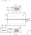
- FIG. 1 is an explanatory diagram schematically illustrating a configuration of a substrate positioning device as an embodiment of the present invention. Note that, in FIG. 1 , an XY orthogonal coordinate system is illustrated.
- FIG. 2 to FIG. 6 are (first to fifth) explanatory diagrams illustrating details of processing of a substrate positioning method using the substrate positioning device.
- FIG. 2 to FIG. 6 correspond to cross-sections taken along the line A-A of FIG. 1 .
- the substrate positioning device of this embodiment is a device that positions a substrate 1 having a rectangular planar shape defined by an X direction (first direction) and a Y direction (second direction) orthogonal to the X direction.
- the substrate positioning device of this embodiment positions the substrate 1 by using the Y direction as a position adjustment direction.
- the substrate positioning device of this embodiment includes a placing table 2, a controller 5, a reference-side positioning mechanism 10, and a pressing positioning mechanism 20.
- the substrate 1 is placed on an upper surface of the placing table 2.
- the substrate 1 is placed on the placing table 2 so that a longitudinal direction of the substrate 1 corresponds to the X direction, and a widthwise direction corresponds to the Y direction.
- the reference-side positioning mechanism 10 and the pressing positioning mechanism 20 are arranged to face each other along the Y direction (position adjustment direction) with respect to the substrate 1 placed on the placing table 2, and to be located on both sides of the substrate 1.
- the controller 5 executes and controls positioning control operation by using the reference-side positioning mechanism 10 and the pressing positioning mechanism 20.
- the reference-side positioning mechanism 10 being a first positioning mechanism includes a base body part 11, an extendible and retractable part 12, and a tip end part 13.
- the base body part 11 being a first fixing part is fixedly arranged at a first fixing position with respect to the placing table 2. Specifically, the base body part 11 is fixedly arranged to be spaced apart by a predetermined distance on a -Y direction side along the Y direction with respect to a placing table center line CL2 of the placing table 2.
- the extendible and retractable part 12 being a first extendible and retractable part is connected to the base body part 11 in an extendible and retractable manner, and performs first extension and retraction operation of extending and retracting along the Y direction.
- the tip end part 13 being a first tip end part is connected to be coupled to the extendible and retractable part 12.
- the position of the tip end part 13 in the Y direction is changed toward a +Y direction (one movement direction) side corresponding to a direction toward the pressing positioning mechanism 20 during extension of the extendible and retractable part 12 in the first extension and retraction operation.
- the position of the tip end part 13 in the Y direction is changed toward the -Y direction (another movement direction) side corresponding to a direction away from the pressing positioning mechanism 20 during retraction in the first extension and retraction operation.
- the reference-side positioning mechanism 10 exerts a first substrate moving force of moving the substrate 1 in the +Y direction side.
- examples of the first extension and retraction operation of the extendible and retractable part 12 include extending and retracting operation achieved by a ball screw using a drive source such as a servomotor and a step motor.
- the pressing positioning mechanism 20 being a second positioning mechanism includes a base body part 21, an extendible and retractable part 22, and a tip end part 23.
- the base body part 21 being a second fixing part is fixedly arranged at a second fixing position with respect to the placing table 2. Specifically, the base body part 21 is fixedly arranged to be spaced apart by a predetermined distance on the +Y direction side along the Y direction with respect to the placing table center line CL2 of the placing table 2.
- the extendible and retractable part 22 being a second extendible and retractable part is connected to the base body part 21 in an extendible and retractable manner, and performs second extension and retraction operation of extending and retracting along the Y direction.
- the tip end part 23 being a second tip end part is connected to be coupled to the extendible and retractable part 22.
- the position of the tip end part 23 in the Y direction is changed toward the -Y direction (another movement direction) side corresponding to a direction toward the reference-side positioning mechanism 10 during extension of the extendible and retractable part 22 in the second extension and retraction operation.
- the position of the tip end part 23 in the Y direction is changed toward the +Y direction (one movement direction) side corresponding to a direction away from the reference-side positioning mechanism 10 during retraction in the second extension and retraction operation.
- the pressing positioning mechanism 20 exerts a second substrate moving force of moving the substrate 1 in the -Y direction side.
- examples of the extendible and retractable part 22 include an air cylinder.
- the controller 5 receives extension and retraction information P10 and extension and retraction information P20 for commanding first and second extension and retraction states of the extendible and retractable parts 12 and 22 from the reference-side positioning mechanism 10 and the pressing positioning mechanism 20. Therefore, based on the extension and retraction information P10, the controller 5 can recognize a first extension and retraction state, which is an extension and retraction state of the extendible and retractable part 12 of the reference-side positioning mechanism 10. Based on the extension and retraction information P20, the controller 5 can recognize an extension and retraction state, which is an extension and retraction state of the extendible and retractable part 22 of the pressing positioning mechanism 20.
- the controller 5 recognizes the first and second extension and retraction states, and simultaneously gives control signals S10 and S20 to the reference-side positioning mechanism 10 and the pressing positioning mechanism 20 to cause the first and second extension and retraction operations to be appropriately executed.
- the controller 5 thereby executes the positioning control operation so that a substrate center line CL1 indicating a center position of the substrate 1 matches the placing table center line CL2 indicating a center position of the placing table 2, in the Y direction being the position adjustment direction.
- FIG. 7 is a flowchart illustrating a procedure of processing of the substrate positioning method using the substrate positioning device of this embodiment. With reference to FIG. 7 as well as to FIG. 1 to FIG. 6 as appropriate, the details of processing of the substrate positioning method will be described below.
- Step S1 initial setting for the substrate positioning device of this embodiment is executed.
- the initial setting is setting in which the substrate 1 is placed on an upper surface of the placing table 2 so as not to come in contact with the reference-side positioning mechanism 10 and the pressing positioning mechanism 20. Note that the initial setting of Step S1 is implemented by using existing technology.
- the reference-side positioning mechanism 10 and the pressing positioning mechanism 20 being the first and second positioning mechanisms are arranged to face each other along the Y direction being the position adjustment direction, and to be located on both sides of the substrate 1. Specifically, arrangement is performed so that a substrate longitudinal direction of the substrate 1 corresponds to the X direction illustrated in FIG. 1 , and a substrate widthwise direction of the substrate 1 corresponds to the Y direction illustrated in FIG. 1 .
- both the first and second extension and retraction states of the extendible and retractable parts 12 and 22 of the reference-side positioning mechanism 10 and the pressing positioning mechanism 20 are most retracted states, and thus the tip end parts 13 and 23 do not come in contact with end portions of the substrate 1.
- Step S1 After execution of Step S1, there is a high probability that a Y-direction error ⁇ D is generated between the substrate center line CL1 of the substrate 1 in the substrate widthwise direction (Y direction) and the placing table center line CL2 of the placing table 2 in the Y direction.
- the substrate positioning device of this embodiment executes the processing of Steps S2 to S6 described below as the positioning control operation performed under the control of the controller 5.
- the controller 5 recognizes the first and second extension and retraction states of the extendible and retractable parts 12 and 22 based on the extension and retraction information P10 and the extension and retraction information P20, and simultaneously outputs the control signals S10 and S20 to the reference-side positioning mechanism 10 and the pressing positioning mechanism 20 to cause the first and second extension and retraction operations to be appropriately executed.
- the controller 5 thereby executes a measurement distance D2 and the positioning control operation.
- Step S2 executed after Step S1, the controller 5 causes the extendible and retractable part 12 to execute the first extension and retraction operation (extension operation).
- the controller 5 stops the first extension and retraction operation and sets to a reference arrangement state.
- reference positioning setting is performed so that a distance from the placing table center line CL2 of the placing table 2 to the tip end part 13 is equal to a reference distance D1.
- the extension and retraction state of the extendible and retractable part 12 refers to an extension and retraction length of the extendible and retractable part 12 (distance between the base body part 11 and the tip end part 13).
- the reference extension and retraction state refers to a state in which the extension and retraction length of the extendible and retractable part 12 is equal to a predetermined reference length.
- a distance between the base body part 11 and the placing table center line CL2 is predetermined. Therefore, by setting the extension and retraction state of the extendible and retractable part 12 to the reference extension and retraction state, a distance from the placing table center line CL2 to the tip end part 13 can be securely set to the reference distance D1.
- the reference distance D1 may be 330 (mm), which is half the designed dimension.
- FIG. 3 illustrates a state out of contact with one end portion (left end portion in FIG. 3 ) of the substrate 1 during the reference arrangement state of the extendible and retractable part 12 of the reference-side positioning mechanism 10.
- one end portion of the substrate 1 may be present at a position beyond the reference distance D1 from the placing table center line CL2 during an initial state illustrated in FIG. 2 .
- the tip end part 13 comes in contact with one end portion of the substrate 1 during execution of the first extension and retraction operation (extension operation) of the extendible and retractable part 12.
- the first substrate moving force of moving the substrate 1 toward the +Y direction side is exerted. Therefore, the substrate 1 is moved so that one end portion of the substrate 1 is located at a position of the reference distance D1 from the placing table center line CL2 during execution of the first extension and retraction operation (extension operation) of the extendible and retractable part 12.
- Step S3 executed after Step S2, as illustrated in FIG. 4 , the controller 5 causes the extendible and retractable part 22 of the pressing positioning mechanism 20 to execute the second extension and retraction operation (extension operation), and thereby executes pressing processing of the substrate 1.
- the tip end part 13 comes in contact with one end portion (left end portion in FIG. 4 ) of the substrate 1, and the tip end part 23 comes in contact with another end portion (right end portion in FIG. 4 ) of the substrate 1.
- the second extension and retraction operation (extension operation) of the pressing positioning mechanism 20 is caused to continue even after execution of Step S3.
- Step S3 when the controller 5 causes the extendible and retractable part 22 to execute the second extension and retraction operation (extension operation), the tip end part 23 comes in contact with another end portion of the substrate 1. After that, a second substrate moving force of moving the substrate 1 toward the -Y direction side is exerted. This moves the substrate 1 in the -Y direction, and the tip end part 13 finally comes in contact with one end portion of the substrate 1.
- the reference-side positioning mechanism 10 exerts a substrate position maintaining force of maintaining the position of the substrate 1.
- the substrate position maintaining force is set to be larger than the second substrate moving force of the pressing positioning mechanism 20.
- the position of the substrate 1 in the Y direction is not changed, irrespective of whether or not the second extension and retraction operation (extension operation) of the pressing positioning mechanism 20 is performed, i.e., even when the pressing positioning mechanism 20 continuously executes the second extension and retraction operation (extension operation).
- the substrate 1 can be stably maintained so that one end portion of the substrate 1 is located at a distance of the reference distance D1 from the placing table center line CL2.
- Step S3 may be executed while one end portion of the substrate 1 is already in contact with the tip end part 13 of the reference-side positioning mechanism 10.
- the tip end part 23 comes in contact with another end portion of the substrate 1 due to the second extension and retraction operation (extension operation) of the extendible and retractable part 22, the position of the substrate 1 is thereafter maintained due to the substrate position maintaining force of the reference-side positioning mechanism 10. Therefore, the processing of Step S3 substantially ends.
- Step S4 executed after Step S3, as illustrated in FIG. 5 , the controller 5 calculates a distance from the placing table center line CL2 to the tip end part 23 as the measurement distance D2, based on the extension and retraction state of the extendible and retractable part 22 of the pressing positioning mechanism 20 recognized with reference to the extension and retraction information P20.
- the extension and retraction state of the extendible and retractable part 22 refers to an extension and retraction length of the extendible and retractable part 22 (distance between the base body part 21 and the tip end part 23).
- a distance between the base body part 21 and the placing table center line CL2 is predetermined. Therefore, the measurement distance D2 being a distance from the placing table center line CL2 to the tip end part 23 can be accurately calculated, based on the extension and retraction state of the extendible and retractable part 22.
- Step S5 the controller 5 calculates a measurement substrate width DW (measurement substrate formation length) being a formation length of the substrate 1 in a direction matching the Y direction being the position adjustment direction, based on the reference distance D1 and the measurement distance D2.
- the measurement substrate width DW is equal to the sum of the reference distance D1 and the measurement distance D2.
- Step S6 as illustrated in FIG. 6 , the controller 5 causes the extendible and retractable parts 12 and 22 to execute the first and second extension and retraction operations so that the substrate center line CL1 of the substrate 1 matches the placing table center line CL2 of the placing table 2. In this manner, the controller 5 performs positioning processing of the substrate center line CL1 of the substrate 1.
- the reference distance D1 is 330 (mm) and the measurement distance D2 is 327 (mm).
- Step S6 the controller 5 causes the extendible and retractable part 12 of the reference-side positioning mechanism 10 to execute the first extension and retraction operation (extension operation).
- extension operation extension operation
- the first substrate moving force of the reference-side positioning mechanism 10 is set to be larger than the second substrate moving force of the pressing positioning mechanism 20. Therefore, even in a state in which the pressing positioning mechanism 20 continuously executes the second extension and retraction operation (extension operation), the substrate 1 can be moved toward the +Y direction side by 1.5 mm due to the first extension and retraction operation (extension operation) of the reference-side positioning mechanism 10.
- substrate positioning processing of correcting the Y-direction error ⁇ D generated during the initial setting state of FIG. 1 , and positioning the substrate center line L1 and the placing table center line CL2 is completed.
- the first and second extension and retraction operations are temporarily stopped.
- the first and second extension and retraction operations are executed, and the substrate 1 is released from the reference-side positioning mechanism 10 and the pressing positioning mechanism 20.
- the first substrate moving force is set to be larger than the second substrate moving force between the reference-side positioning mechanism 10 and the pressing positioning mechanism 20. Therefore, even in a state in which the pressing positioning mechanism 20 exerts the second substrate moving force, the substrate 1 can be smoothly moved toward the +Y direction (one movement direction) side due to the first substrate moving force of the reference-side positioning mechanism 10.
- the substrate 1 can be moved toward the +Y direction side due to the first substrate moving force of the reference-side positioning mechanism 10, irrespective of whether or not the second extension and retraction operation of the pressing positioning mechanism 20 is performed. Consequently, the positioning control operation can be simplified.
- the reference distance D1 is 330 (mm) and the measurement distance D2 is 333 (mm).
- Step S6 the extendible and retractable part 12 of the reference-side positioning mechanism 10 is caused to execute the first extension and retraction operation (retraction operation). After the extension and retraction state of the extendible and retractable part 12 is caused to be retracted from the reference length by 1.5 mm, the first extension and retraction operation (retraction operation) is stopped, and the reference-side positioning mechanism 10 is caused to exert the substrate position maintaining force again.
- the substrate 1 can be moved toward the -Y direction side by 1.5 mm, and the substrate center line CL1 and the placing table center line CL2 can be positioned.
- the positioning control operation can be accurately executed with a relatively simple configuration.
- the relatively simple configuration refers to a configuration including main drive parts of the reference-side positioning mechanism 10 and the pressing positioning mechanism 20 arranged to face each other along the Y direction being the position adjustment direction, and to be located on both sides of the substrate 1.
- the positioning control operation can be accurately executed through a series of relatively simple processing (S2 to S6) without the necessity of a dedicated sensor.
- the relatively simple processing refers to processing in which the first and second extension and retraction states of the extendible and retractable parts 12 and 22 are recognized based on the extension and retraction information P10 and the extension and retraction information P20.
- Step S1 the most part of the processing (Steps S2 to S6), except Step S1, is executed as the positioning control operation of the controller 5. Consequently, after the initial setting of Step S1, the substrate positioning processing can be automatically performed by the substrate positioning device of this embodiment.
- examples of the substrate 1 include a glass substrate for a solar battery.
- the glass substrate placed on the placing table 2 is positioned so that a center position of the glass substrate matches a center position of the placing table by the substrate positioning device of this embodiment. In this manner, the solar battery can be manufactured with its electrode accurately formed on the glass substrate.
- the Y direction being the substrate widthwise direction of the substrate 1 is used as the position adjustment direction.
- the X direction being the substrate longitudinal direction of the substrate 1 is used as the position adjustment direction.
- the reference-side positioning mechanism 10 and the pressing positioning mechanism 20 are arranged to face each other along the X direction (position adjustment direction) with respect to the substrate 1 placed on the placing table 2, and to be located on both sides of the substrate 1.
- the controller 5 uses the reference-side positioning mechanism 10 and the pressing positioning mechanism 20 to execute and control the positioning control operation so that the center position (center position in the substrate longitudinal direction) of the substrate 1 matches the center position of the placing table 2, in the X direction.
Landscapes
- Container, Conveyance, Adherence, Positioning, Of Wafer (AREA)
Abstract
Description
- The present invention relates to a substrate positioning device and a substrate positioning method for determining a placement position of a substrate, such as a glass substrate used in a solar battery, on a placing table.
- When a solar battery or the like is manufactured by placing a substrate on a placing table and performing various manufacturing processes on the substrate, there is a great necessity that the substrate be accurately positioned and placed on the placing table.
- For example, when a substrate is a glass substrate for a thin-film solar battery, the glass substrate needs to be accurately positioned and disposed on a placing table prior to a process for an electrode in which a power collection electrode is joined on the glass substrate.
- As such technology for positioning a glass substrate described above, for example,
Patent Document 1 discloses a method and an apparatus for machining a glass substrate. - Patent Document 1:
WO 2009/119772 A1 - The conventional substrate positioning technology disclosed in
Patent Document 1, for example, at the time of substrate positioning in a substrate widthwise direction of a substrate, positioning is performed in consideration of a maximum substrate width error of a substrate width of a substrate to be manufactured. Therefore, the position of the substrate is inevitably shifted by an amount corresponding to an error of the substrate width. - For example, when there is an error of "600±0.8" (mm) in a substrate width, in consideration of a maximum value of the error, positioning is performed assuming that the substrate width is 600.8 mm. Therefore, when an actual substrate width is a minimum value of 599.2 mm, the position is inevitably shifted by 1.6 (= 600.8 - 599.2) mm.
- There has been a problem in that an electrode cannot be formed with the above-mentioned electrode position accuracy being satisfied at the same time in an electrode manufacturing process. Specifically, such a problem occurs when a substrate is a glass substrate for a thin-film solar battery, and an electrode is formed with a substrate width center of a substrate being used as a reference and required electrode position accuracy is finer than 1.6 mm described above in an electrode manufacturing process in which a power collection electrode is joined on the glass substrate.
- Note that, when an electrode is disposed with an end portion of a glass substrate being used as a reference in the electrode manufacturing process described above, the glass substrate is only required to be pressed toward a fixed reference side to enable disposition of an electrode with mechanical dimensional accuracy. In contrast, when an electrode is disposed with a center of a glass substrate being used as a reference, dimensional accuracy of a substrate width of a substrate directly affects center position accuracy of the glass substrate, which causes a problem in that an electrode cannot be formed with the above-mentioned electrode position accuracy being satisfied at the same time as described above.
- In the technology disclosed in
Patent Document 1, a substrate width of a glass substrate is measured prior to machining to perform subsequent machining. Because the glass substrate is positioned with its one end portion being used as a reference, the problem described above cannot be solved when a manufacturing process needs to be performed with a substrate width center of the glass substrate being used as a reference. - The present invention has an object to provide a substrate positioning device capable of solving the problems as described above, and implementing positioning of a substrate at a center position with a relatively simple configuration.
- The present invention is intended for a substrate positioning device that positions a substrate having a rectangular planar shape defined by a first direction and a second direction orthogonal to the first direction. The substrate positioning device positions the substrate in a position adjustment direction being one direction out of the first and second directions. The substrate positioning device includes a placing table, first and second positioning mechanisms, and a controller. On the placing table, the substrate is placed. The first and second positioning mechanisms are arranged to face each other along the position adjustment direction with respect to the substrate placed on the placing table, and to be located on both sides of the substrate. The controller is provided for control of the first and second positioning mechanisms. The first positioning mechanism includes a first fixing part, a first extendible and retractable part, and a first tip end part. The first fixing part is fixedly arranged at a first fixing position with respect to the placing table. The first extendible and retractable part is connected to the first fixing part in an extendible and retractable manner, and is configured to perform first extension and retraction operation of extending and retracting along the position adjustment direction. The first tip end part is connected to be coupled to the first extendible and retractable part. A position of the first tip end part in the position adjustment direction is changed toward one movement direction side corresponding to a direction toward the second positioning mechanism during extension in the first extension and retraction operation. A position of the first tip end part in the position adjustment direction is changed toward another movement direction side corresponding to a direction away from the second positioning mechanism during retraction in the first extension and retraction operation. After the first tip end part comes in contact with one end portion of the substrate during extension in the first extension and retraction operation, the first positioning mechanism exerts a first substrate moving force of moving the substrate in the one movement direction side. The second positioning mechanism includes a second fixing part, a second extendible and retractable part, and a second tip end part. The second fixing part is fixedly arranged at a second fixing position with respect to the placing table. The second extendible and retractable part is connected to the second fixing part in an extendible and retractable manner, and is configured to perform second extension and retraction operation of extending and retracting along the position adjustment direction. The second tip end part is connected to the second extendible and retractable part. A position of the second tip end part in the position adjustment direction is changed toward the another movement direction side corresponding to a direction toward the first positioning mechanism during extension in the second extension and retraction operation. A position of the second tip end part in the position adjustment direction is changed toward the one movement direction side corresponding to a direction away from the first positioning mechanism during retraction in the second extension and retraction operation. After the second tip end part comes in contact with another end portion of the substrate during extension in the second extension and retraction operation, the second positioning mechanism exerts a second substrate moving force of moving the substrate in the another movement direction side. The controller recognizes first and second extension and retraction states of the first and second extendible and retractable parts, and simultaneously causes the first and second extension and retraction operations to be executed, and the controller thereby executes positioning control operation so that a center position of the substrate matches a center position of the placing table, in the position adjustment direction.
- According to the substrate positioning device of the present invention, positioning control operation can be accurately executed with a relatively simple configuration, and through relatively simple processing without the necessity of a dedicated sensor. The relatively simple configuration refers to a configuration including main configuration parts of the first and second positioning mechanisms arranged to face each other along the position adjustment direction, and to be located on both sides of the substrate. The relatively simple processing refers to processing in which the first and second extension and retraction states of the first and second extendible and retractable parts are recognized.
- These and other objects, features, aspects and advantages of the present invention will become more apparent from the following detailed description of the present invention when taken in conjunction with the accompanying drawings.
-
-
FIG. 1 is an explanatory diagram schematically illustrating a configuration of a substrate positioning device as an embodiment of the present invention. -
FIG. 2 is a (first) explanatory diagram illustrating details of processing of a substrate positioning method using the substrate positioning device. -
FIG. 3 is a (second) explanatory diagram illustrating details of processing of the substrate positioning method using the substrate positioning device. -
FIG. 4 is a (third) explanatory diagram illustrating details of processing of the substrate positioning method using the substrate positioning device. -
FIG. 5 is a (fourth) explanatory diagram illustrating details of processing of the substrate positioning method using the substrate positioning device. -
FIG. 6 is a (fifth) explanatory diagram illustrating details of processing of the substrate positioning method using the substrate positioning device. -
FIG. 7 is a flowchart illustrating a procedure of processing of the substrate positioning method using the substrate positioning device of this embodiment. -
FIG. 1 is an explanatory diagram schematically illustrating a configuration of a substrate positioning device as an embodiment of the present invention. Note that, inFIG. 1 , an XY orthogonal coordinate system is illustrated. -
FIG. 2 to FIG. 6 are (first to fifth) explanatory diagrams illustrating details of processing of a substrate positioning method using the substrate positioning device.FIG. 2 to FIG. 6 correspond to cross-sections taken along the line A-A ofFIG. 1 . - As illustrated in these figures, the substrate positioning device of this embodiment is a device that positions a
substrate 1 having a rectangular planar shape defined by an X direction (first direction) and a Y direction (second direction) orthogonal to the X direction. The substrate positioning device of this embodiment positions thesubstrate 1 by using the Y direction as a position adjustment direction. - The substrate positioning device of this embodiment includes a placing table 2, a
controller 5, a reference-side positioning mechanism 10, and apressing positioning mechanism 20. - The
substrate 1 is placed on an upper surface of the placing table 2. Thesubstrate 1 is placed on the placing table 2 so that a longitudinal direction of thesubstrate 1 corresponds to the X direction, and a widthwise direction corresponds to the Y direction. - The reference-
side positioning mechanism 10 and thepressing positioning mechanism 20 are arranged to face each other along the Y direction (position adjustment direction) with respect to thesubstrate 1 placed on the placing table 2, and to be located on both sides of thesubstrate 1. - The
controller 5 executes and controls positioning control operation by using the reference-side positioning mechanism 10 and thepressing positioning mechanism 20. - As illustrated in
FIG. 2 to FIG. 6 , the reference-side positioning mechanism 10 being a first positioning mechanism includes abase body part 11, an extendible andretractable part 12, and atip end part 13. - The
base body part 11 being a first fixing part is fixedly arranged at a first fixing position with respect to the placing table 2. Specifically, thebase body part 11 is fixedly arranged to be spaced apart by a predetermined distance on a -Y direction side along the Y direction with respect to a placing table center line CL2 of the placing table 2. - The extendible and
retractable part 12 being a first extendible and retractable part is connected to thebase body part 11 in an extendible and retractable manner, and performs first extension and retraction operation of extending and retracting along the Y direction. - The
tip end part 13 being a first tip end part is connected to be coupled to the extendible andretractable part 12. The position of thetip end part 13 in the Y direction is changed toward a +Y direction (one movement direction) side corresponding to a direction toward thepressing positioning mechanism 20 during extension of the extendible andretractable part 12 in the first extension and retraction operation. The position of thetip end part 13 in the Y direction is changed toward the -Y direction (another movement direction) side corresponding to a direction away from thepressing positioning mechanism 20 during retraction in the first extension and retraction operation. - Therefore, after the
tip end part 13 comes in contact with one end portion (left end portion illustrated inFIG. 2 to FIG. 6 ) of thesubstrate 1 during extension of the extendible andretractable part 12 in the first extension and retraction operation, the reference-side positioning mechanism 10 exerts a first substrate moving force of moving thesubstrate 1 in the +Y direction side. - Note that examples of the first extension and retraction operation of the extendible and
retractable part 12 include extending and retracting operation achieved by a ball screw using a drive source such as a servomotor and a step motor. - The
pressing positioning mechanism 20 being a second positioning mechanism includes abase body part 21, an extendible andretractable part 22, and atip end part 23. - The
base body part 21 being a second fixing part is fixedly arranged at a second fixing position with respect to the placing table 2. Specifically, thebase body part 21 is fixedly arranged to be spaced apart by a predetermined distance on the +Y direction side along the Y direction with respect to the placing table center line CL2 of the placing table 2. - The extendible and
retractable part 22 being a second extendible and retractable part is connected to thebase body part 21 in an extendible and retractable manner, and performs second extension and retraction operation of extending and retracting along the Y direction. - The
tip end part 23 being a second tip end part is connected to be coupled to the extendible andretractable part 22. The position of thetip end part 23 in the Y direction is changed toward the -Y direction (another movement direction) side corresponding to a direction toward the reference-side positioning mechanism 10 during extension of the extendible andretractable part 22 in the second extension and retraction operation. The position of thetip end part 23 in the Y direction is changed toward the +Y direction (one movement direction) side corresponding to a direction away from the reference-side positioning mechanism 10 during retraction in the second extension and retraction operation. - Therefore, after the
tip end part 23 comes in contact with another end portion (right end portion illustrated inFIG. 2 to FIG. 6 ) of thesubstrate 1 during extension of the extendible andretractable part 22 in the second extension and retraction operation, thepressing positioning mechanism 20 exerts a second substrate moving force of moving thesubstrate 1 in the -Y direction side. - Note that examples of the extendible and
retractable part 22 include an air cylinder. - The
controller 5 receives extension and retraction information P10 and extension and retraction information P20 for commanding first and second extension and retraction states of the extendible andretractable parts side positioning mechanism 10 and thepressing positioning mechanism 20. Therefore, based on the extension and retraction information P10, thecontroller 5 can recognize a first extension and retraction state, which is an extension and retraction state of the extendible andretractable part 12 of the reference-side positioning mechanism 10. Based on the extension and retraction information P20, thecontroller 5 can recognize an extension and retraction state, which is an extension and retraction state of the extendible andretractable part 22 of thepressing positioning mechanism 20. - The
controller 5 recognizes the first and second extension and retraction states, and simultaneously gives control signals S10 and S20 to the reference-side positioning mechanism 10 and thepressing positioning mechanism 20 to cause the first and second extension and retraction operations to be appropriately executed. Thecontroller 5 thereby executes the positioning control operation so that a substrate center line CL1 indicating a center position of thesubstrate 1 matches the placing table center line CL2 indicating a center position of the placing table 2, in the Y direction being the position adjustment direction. -
FIG. 7 is a flowchart illustrating a procedure of processing of the substrate positioning method using the substrate positioning device of this embodiment. With reference toFIG. 7 as well as toFIG. 1 to FIG. 6 as appropriate, the details of processing of the substrate positioning method will be described below. - First, in Step S1, initial setting for the substrate positioning device of this embodiment is executed. The initial setting is setting in which the
substrate 1 is placed on an upper surface of the placing table 2 so as not to come in contact with the reference-side positioning mechanism 10 and thepressing positioning mechanism 20. Note that the initial setting of Step S1 is implemented by using existing technology. - After execution of Step S1, as illustrated in
FIG. 1 , the reference-side positioning mechanism 10 and thepressing positioning mechanism 20 being the first and second positioning mechanisms are arranged to face each other along the Y direction being the position adjustment direction, and to be located on both sides of thesubstrate 1. Specifically, arrangement is performed so that a substrate longitudinal direction of thesubstrate 1 corresponds to the X direction illustrated inFIG. 1 , and a substrate widthwise direction of thesubstrate 1 corresponds to the Y direction illustrated inFIG. 1 . - As illustrated in
FIG. 2 , during the initial setting, both the first and second extension and retraction states of the extendible andretractable parts side positioning mechanism 10 and thepressing positioning mechanism 20 are most retracted states, and thus thetip end parts substrate 1. - As illustrated in
FIG. 1 , after execution of Step S1, there is a high probability that a Y-direction error ΔD is generated between the substrate center line CL1 of thesubstrate 1 in the substrate widthwise direction (Y direction) and the placing table center line CL2 of the placing table 2 in the Y direction. - In view of this, to bring the Y-direction error ΔD to "0," the substrate positioning device of this embodiment executes the processing of Steps S2 to S6 described below as the positioning control operation performed under the control of the
controller 5. Thecontroller 5 recognizes the first and second extension and retraction states of the extendible andretractable parts side positioning mechanism 10 and thepressing positioning mechanism 20 to cause the first and second extension and retraction operations to be appropriately executed. Thecontroller 5 thereby executes a measurement distance D2 and the positioning control operation. - First, in Step S2 executed after Step S1, the
controller 5 causes the extendible andretractable part 12 to execute the first extension and retraction operation (extension operation). After thecontroller 5 causes the extension and retraction state of the extendible andretractable part 12 to be a reference extension and retraction state, thecontroller 5 stops the first extension and retraction operation and sets to a reference arrangement state. As a result, as illustrated inFIG. 3 , reference positioning setting is performed so that a distance from the placing table center line CL2 of the placing table 2 to thetip end part 13 is equal to a reference distance D1. - The extension and retraction state of the extendible and
retractable part 12 refers to an extension and retraction length of the extendible and retractable part 12 (distance between thebase body part 11 and the tip end part 13). The reference extension and retraction state refers to a state in which the extension and retraction length of the extendible andretractable part 12 is equal to a predetermined reference length. - A distance between the
base body part 11 and the placing table center line CL2 is predetermined. Therefore, by setting the extension and retraction state of the extendible andretractable part 12 to the reference extension and retraction state, a distance from the placing table center line CL2 to thetip end part 13 can be securely set to the reference distance D1. Note that, for example, if a designed dimension of a substrate width of thesubstrate 1 is 660 (mm), the reference distance D1 may be 330 (mm), which is half the designed dimension. - Note that
FIG. 3 illustrates a state out of contact with one end portion (left end portion inFIG. 3 ) of thesubstrate 1 during the reference arrangement state of the extendible andretractable part 12 of the reference-side positioning mechanism 10. In contrast, one end portion of thesubstrate 1 may be present at a position beyond the reference distance D1 from the placing table center line CL2 during an initial state illustrated inFIG. 2 . In this case, thetip end part 13 comes in contact with one end portion of thesubstrate 1 during execution of the first extension and retraction operation (extension operation) of the extendible andretractable part 12. After that, the first substrate moving force of moving thesubstrate 1 toward the +Y direction side is exerted. Therefore, thesubstrate 1 is moved so that one end portion of thesubstrate 1 is located at a position of the reference distance D1 from the placing table center line CL2 during execution of the first extension and retraction operation (extension operation) of the extendible andretractable part 12. - After that, in Step S3 executed after Step S2, as illustrated in
FIG. 4 , thecontroller 5 causes the extendible andretractable part 22 of thepressing positioning mechanism 20 to execute the second extension and retraction operation (extension operation), and thereby executes pressing processing of thesubstrate 1. - As a result of the pressing processing of the substrate performed by the
pressing positioning mechanism 20, finally, thetip end part 13 comes in contact with one end portion (left end portion inFIG. 4 ) of thesubstrate 1, and thetip end part 23 comes in contact with another end portion (right end portion inFIG. 4 ) of thesubstrate 1. Note that the second extension and retraction operation (extension operation) of thepressing positioning mechanism 20 is caused to continue even after execution of Step S3. - Specifically, in Step S3, when the
controller 5 causes the extendible andretractable part 22 to execute the second extension and retraction operation (extension operation), thetip end part 23 comes in contact with another end portion of thesubstrate 1. After that, a second substrate moving force of moving thesubstrate 1 toward the -Y direction side is exerted. This moves thesubstrate 1 in the -Y direction, and thetip end part 13 finally comes in contact with one end portion of thesubstrate 1. - When the
base body part 11 is in contact with one end portion of thesubstrate 1 during the reference arrangement state, the reference-side positioning mechanism 10 exerts a substrate position maintaining force of maintaining the position of thesubstrate 1. The substrate position maintaining force is set to be larger than the second substrate moving force of thepressing positioning mechanism 20. - Therefore, when the position of the
substrate 1 is maintained due to the substrate position maintaining force of the reference-side positioning mechanism 10, the position of thesubstrate 1 in the Y direction is not changed, irrespective of whether or not the second extension and retraction operation (extension operation) of thepressing positioning mechanism 20 is performed, i.e., even when thepressing positioning mechanism 20 continuously executes the second extension and retraction operation (extension operation). In this manner, due to the substrate position maintaining force of the reference-side positioning mechanism 10, thesubstrate 1 can be stably maintained so that one end portion of thesubstrate 1 is located at a distance of the reference distance D1 from the placing table center line CL2. - Moreover, after execution of Step S2, Step S3 may be executed while one end portion of the
substrate 1 is already in contact with thetip end part 13 of the reference-side positioning mechanism 10. In this case, when thetip end part 23 comes in contact with another end portion of thesubstrate 1 due to the second extension and retraction operation (extension operation) of the extendible andretractable part 22, the position of thesubstrate 1 is thereafter maintained due to the substrate position maintaining force of the reference-side positioning mechanism 10. Therefore, the processing of Step S3 substantially ends. - In Step S4 executed after Step S3, as illustrated in
FIG. 5 , thecontroller 5 calculates a distance from the placing table center line CL2 to thetip end part 23 as the measurement distance D2, based on the extension and retraction state of the extendible andretractable part 22 of thepressing positioning mechanism 20 recognized with reference to the extension and retraction information P20. - The extension and retraction state of the extendible and
retractable part 22 refers to an extension and retraction length of the extendible and retractable part 22 (distance between thebase body part 21 and the tip end part 23). A distance between thebase body part 21 and the placing table center line CL2 is predetermined. Therefore, the measurement distance D2 being a distance from the placing table center line CL2 to thetip end part 23 can be accurately calculated, based on the extension and retraction state of the extendible andretractable part 22. - After that, in Step S5, the
controller 5 calculates a measurement substrate width DW (measurement substrate formation length) being a formation length of thesubstrate 1 in a direction matching the Y direction being the position adjustment direction, based on the reference distance D1 and the measurement distance D2. The measurement substrate width DW is equal to the sum of the reference distance D1 and the measurement distance D2. - Finally, in Step S6, as illustrated in
FIG. 6 , based on the measurement substrate width DW, thecontroller 5 causes the extendible andretractable parts substrate 1 matches the placing table center line CL2 of the placing table 2. In this manner, thecontroller 5 performs positioning processing of the substrate center line CL1 of thesubstrate 1. - A first case will be discussed below. In the first case, for example, the reference distance D1 is 330 (mm) and the measurement distance D2 is 327 (mm). In the first case, in Step S5, the measurement substrate width DW is calculated as 657 (mm) (= 330 + 327 (mm)), and thus a 1/2 substrate width DWH is 328.5 (mm) (657/2 (mm)).
- Therefore, the
controller 5 can recognize that the position of thesubstrate 1 is shifted from the placing table center line CL2 toward the -Y direction side by 1.5 mm (= 330 - 328.5 (mm)). - Therefore, in Step S6, as illustrated in
FIG. 6 , thecontroller 5 causes the extendible andretractable part 12 of the reference-side positioning mechanism 10 to execute the first extension and retraction operation (extension operation). After thecontroller 5 causes the extension and retraction state of the extendible andretractable part 12 to be extended from the reference length by 1.5 mm, thecontroller 5 stops the first extension and retraction operation, and causes the reference-side positioning mechanism 10 to exert the substrate position maintaining force again. - In this case, the first substrate moving force of the reference-
side positioning mechanism 10 is set to be larger than the second substrate moving force of thepressing positioning mechanism 20. Therefore, even in a state in which thepressing positioning mechanism 20 continuously executes the second extension and retraction operation (extension operation), thesubstrate 1 can be moved toward the +Y direction side by 1.5 mm due to the first extension and retraction operation (extension operation) of the reference-side positioning mechanism 10. - As a result, as illustrated in
FIG. 6 , substrate positioning processing of correcting the Y-direction error ΔD generated during the initial setting state ofFIG. 1 , and positioning the substrate center line L1 and the placing table center line CL2 is completed. After completion of the substrate positioning processing, under the control of thecontroller 5, the first and second extension and retraction operations are temporarily stopped. Then, the first and second extension and retraction operations (both are retraction operations) are executed, and thesubstrate 1 is released from the reference-side positioning mechanism 10 and thepressing positioning mechanism 20. - In this manner, the first substrate moving force is set to be larger than the second substrate moving force between the reference-
side positioning mechanism 10 and thepressing positioning mechanism 20. Therefore, even in a state in which thepressing positioning mechanism 20 exerts the second substrate moving force, thesubstrate 1 can be smoothly moved toward the +Y direction (one movement direction) side due to the first substrate moving force of the reference-side positioning mechanism 10. - Therefore, according to the substrate positioning device of this embodiment, the
substrate 1 can be moved toward the +Y direction side due to the first substrate moving force of the reference-side positioning mechanism 10, irrespective of whether or not the second extension and retraction operation of thepressing positioning mechanism 20 is performed. Consequently, the positioning control operation can be simplified. - As such simplified positioning control operation, for example, there is an operation in which extension operation of the second extension and retraction operation of the
pressing positioning mechanism 20 is only necessary to be continuously executed in Steps S3 to S6. - Next, a second case will be discussed below. In the second case, for example, the reference distance D1 is 330 (mm) and the measurement distance D2 is 333 (mm). In the second case, in Step S5, the measurement substrate width DW is calculated as 663 (mm) (= 330 + 333 (mm)), and thus the 1/2 substrate width DWH is 331.5 (mm).
- Therefore, the
controller 5 can recognize that the position of thesubstrate 1 is shifted from the placing table center line CL2 toward the +Y direction side by 1.5 mm (= 331.5 - 300 (mm)). - Therefore, in Step S6, the extendible and
retractable part 12 of the reference-side positioning mechanism 10 is caused to execute the first extension and retraction operation (retraction operation). After the extension and retraction state of the extendible andretractable part 12 is caused to be retracted from the reference length by 1.5 mm, the first extension and retraction operation (retraction operation) is stopped, and the reference-side positioning mechanism 10 is caused to exert the substrate position maintaining force again. - As a result, due to the continuously executed second extension and retraction operation (extension operation) of the
pressing positioning mechanism 20, thesubstrate 1 can be moved toward the -Y direction side by 1.5 mm, and the substrate center line CL1 and the placing table center line CL2 can be positioned. - In this manner, according to the substrate positioning device of this embodiment, the positioning control operation can be accurately executed with a relatively simple configuration. The relatively simple configuration refers to a configuration including main drive parts of the reference-
side positioning mechanism 10 and thepressing positioning mechanism 20 arranged to face each other along the Y direction being the position adjustment direction, and to be located on both sides of thesubstrate 1. - Moreover, according to the substrate positioning device of this embodiment, the positioning control operation can be accurately executed through a series of relatively simple processing (S2 to S6) without the necessity of a dedicated sensor. The relatively simple processing refers to processing in which the first and second extension and retraction states of the extendible and
retractable parts - In addition, according to the substrate positioning method executed using the substrate positioning device of this embodiment, the most part of the processing (Steps S2 to S6), except Step S1, is executed as the positioning control operation of the
controller 5. Consequently, after the initial setting of Step S1, the substrate positioning processing can be automatically performed by the substrate positioning device of this embodiment. - Note that examples of the
substrate 1 include a glass substrate for a solar battery. - When such a glass substrate is used in a solar battery whose electrode is formed with the center of the glass substrate being used as a reference, the glass substrate placed on the placing table 2 is positioned so that a center position of the glass substrate matches a center position of the placing table by the substrate positioning device of this embodiment. In this manner, the solar battery can be manufactured with its electrode accurately formed on the glass substrate.
- Note that, in the substrate positioning device of this embodiment, the Y direction being the substrate widthwise direction of the
substrate 1 is used as the position adjustment direction. However, there may be another mode in which the X direction being the substrate longitudinal direction of thesubstrate 1 is used as the position adjustment direction. - In such another mode, the reference-
side positioning mechanism 10 and thepressing positioning mechanism 20 are arranged to face each other along the X direction (position adjustment direction) with respect to thesubstrate 1 placed on the placing table 2, and to be located on both sides of thesubstrate 1. - The
controller 5 uses the reference-side positioning mechanism 10 and thepressing positioning mechanism 20 to execute and control the positioning control operation so that the center position (center position in the substrate longitudinal direction) of thesubstrate 1 matches the center position of the placing table 2, in the X direction. - While the invention has been shown and described in detail, the foregoing description is in all aspects illustrative and not restrictive. It is therefore understood that numerous unillustrated modifications and variations can be devised without departing from the scope of the invention.
-
- 1
- substrate
- 2
- placing table
- 5
- controller
- 10
- reference-side positioning mechanism
- 11, 21
- base body part
- 12, 22
- extendible and retractable part
- 13, 23
- tip end part
- 20
- pressing positioning mechanism
Claims (5)
- A substrate positioning device that positions a substrate (1) having a rectangular planar shape defined by a first direction and a second direction orthogonal to said first direction, said substrate positioning device positioning said substrate in a position adjustment direction being one direction out of said first and second directions, said substrate positioning device comprising:a placing table (2) on which said substrate is placed;first and second positioning mechanisms (10, 20) arranged to face each other along said position adjustment direction with respect to said substrate placed on said placing table, and to be located on both sides of said substrate; anda controller (5) provided for control of said first and second positioning mechanisms, whereinsaid first positioning mechanism (10) includes:a first fixing part (11) fixedly arranged at a first fixing position with respect to said placing table;a first extendible and retractable part (12) being connected to said first fixing part in an extendible and retractable manner, and being configured to perform first extension and retraction operation of extending and retracting along said position adjustment direction; anda first tip end part (13) being connected to be coupled to said first extendible and retractable part, a position of said first tip end part in said position adjustment direction being changed toward one movement direction side corresponding to a direction toward said second positioning mechanism during extension in said first extension and retraction operation, a position of said first tip end part in said position adjustment direction being changed toward another movement direction side corresponding to a direction away from said second positioning mechanism during retraction in said first extension and retraction operation,after said first tip end part comes in contact with one end portion of said substrate during extension in said first extension and retraction operation, said first positioning mechanism exerts a first substrate moving force of moving said substrate in said one movement direction side,said second positioning mechanism (20) includes:a second fixing part (21) fixedly arranged at a second fixing position with respect to said placing table;a second extendible and retractable part (22) being connected to said second fixing part in an extendible and retractable manner, and being configured to perform second extension and retraction operation of extending and retracting along said position adjustment direction; anda second tip end part (23) being connected to said second extendible and retractable part, a position of said second tip end part in said position adjustment direction being changed toward said another movement direction side corresponding to a direction toward said first positioning mechanism during extension in said second extension and retraction operation, a position of said second tip end part in said position adjustment direction being changed toward said one movement direction side corresponding to a direction away from said first positioning mechanism during retraction in said second extension and retraction operation,after said second tip end part comes in contact with another end portion of said substrate during extension in said second extension and retraction operation, said second positioning mechanism exerts a second substrate moving force of moving said substrate in said another movement direction side, andsaid controller recognizes first and second extension and retraction states of said first and second extendible and retractable parts, and simultaneously causes said first and second extension and retraction operations to be executed, and said controller thereby executes positioning control operation so that a center position (CL1) of said substrate matches a center position (CL2) of said placing table, in said position adjustment direction.
- The substrate positioning device according to claim 1, wherein
when said first tip end part is in contact with one end portion of said substrate during a reference arrangement state, said first positioning mechanism exerts a substrate position maintaining force of maintaining a position of said substrate, said reference arrangement state being a state in which said first extension and retraction state of said first extendible and retractable part is caused to be a reference extension and retraction state, and in which said first extension and retraction operation is stopped, and
said substrate position maintaining force is larger than said second substrate moving force exerted by said second positioning mechanism. - The substrate positioning device according to claim 2, wherein
said first substrate moving force is larger than said second substrate moving force. - The substrate positioning device according to any one of claims 1 to 3, wherein
said substrate includes a glass substrate for a solar battery. - A substrate positioning method of positioning a substrate using said substrate positioning device of claim 2 or 3, said substrate positioning method comprising the steps of:(a) performing initial setting for said substrate positioning device, said initial setting being setting in which said substrate is placed on said placing table so as not to come in contact with said first and second positioning mechanisms, whereinafter execution of said step (a), said first and second positioning mechanisms are arranged to face each other along said position adjustment direction, and to be located on both sides of said substrate,
the substrate positioning method further comprises the steps of:(b) after execution of said step (a), causing said first extendible and retractable part to execute said first extension and retraction operation, and after causing a first extension and retraction state of said first extendible and retractable part to be said reference extension and retraction state, stopping said first extension and retraction operation and setting to said reference arrangement state, so that a distance from a center of said placing table to said first tip end part is equal to a reference distance (D1);(c) after execution of said step (b), causing said second extendible and retractable part to execute said second extension and retraction operation, so that said first tip end part comes in contact with one end portion of said substrate, and said second tip end part comes in contact with another end portion of said substrate;(d) after execution of said step (c), calculating a distance from the center of said placing table to said second tip end part as a measurement distance (D2), based on a second extension and retraction state of said second extendible and retractable part;(e) calculating a formation length of said substrate in a direction matching said position adjustment direction out of said first and second directions as a measurement substrate formation length (DW), based on said reference distance and said measurement distance; and(f) based on said measurement substrate formation length, causing said first and second extension and retraction operations so that the center (CL1) of said substrate matches the center (CL2) of said placing table, andsaid steps (b) to (f) are executed as said positioning control operation of said controller.
Applications Claiming Priority (1)
| Application Number | Priority Date | Filing Date | Title |
|---|---|---|---|
| PCT/JP2017/024071 WO2019003403A1 (en) | 2017-06-30 | 2017-06-30 | Substrate positioning device and substrate positioning method |
Publications (3)
| Publication Number | Publication Date |
|---|---|
| EP3648153A1 true EP3648153A1 (en) | 2020-05-06 |
| EP3648153A4 EP3648153A4 (en) | 2021-02-24 |
| EP3648153B1 EP3648153B1 (en) | 2023-01-04 |
Family
ID=64742072
Family Applications (1)
| Application Number | Title | Priority Date | Filing Date |
|---|---|---|---|
| EP17916094.0A Active EP3648153B1 (en) | 2017-06-30 | 2017-06-30 | Substrate positioning device and substrate positioning method |
Country Status (5)
| Country | Link |
|---|---|
| EP (1) | EP3648153B1 (en) |
| JP (1) | JP6733056B2 (en) |
| CN (1) | CN110832633B (en) |
| TW (1) | TWI675495B (en) |
| WO (1) | WO2019003403A1 (en) |
Families Citing this family (1)
| Publication number | Priority date | Publication date | Assignee | Title |
|---|---|---|---|---|
| CN111332788B (en) * | 2020-03-12 | 2021-08-03 | 徐州谷阳新能源科技有限公司 | A kind of coating automation equipment taking and positioning method |
Family Cites Families (24)
| Publication number | Priority date | Publication date | Assignee | Title |
|---|---|---|---|---|
| JPH09107011A (en) * | 1995-10-11 | 1997-04-22 | Sharp Corp | Semiconductor device and method of aligning the semiconductor device |
| JPH1068918A (en) * | 1996-08-26 | 1998-03-10 | Toshiba Electron Eng Corp | Substrate positioning method and apparatus |
| JPH10116882A (en) * | 1996-10-15 | 1998-05-06 | Olympus Optical Co Ltd | Equipment and method for positioning wafer |
| JP2000068354A (en) * | 1998-08-26 | 2000-03-03 | Dainippon Screen Mfg Co Ltd | Carrier positioning mechanism |
| JP2002043394A (en) * | 2000-07-19 | 2002-02-08 | Tokyo Electron Ltd | Position shift detecting device and processing system |
| JP3879497B2 (en) * | 2001-12-04 | 2007-02-14 | 凸版印刷株式会社 | Glass substrate positioning device |
| JP2003229470A (en) * | 2002-02-06 | 2003-08-15 | Orc Mfg Co Ltd | Preliminary positioning mechanism and method therefor |
| JP4292573B2 (en) * | 2003-05-13 | 2009-07-08 | 株式会社ニコン | Stage apparatus and exposure apparatus |
| JP2006344675A (en) * | 2005-06-07 | 2006-12-21 | Dainippon Printing Co Ltd | Substrate positioning method and apparatus |
| JP4548239B2 (en) * | 2005-06-21 | 2010-09-22 | パナソニック株式会社 | Substrate bonding method and substrate bonding apparatus |
| JP2007221070A (en) * | 2006-02-20 | 2007-08-30 | Dainippon Screen Mfg Co Ltd | Substrate positioning method, substrate positioning apparatus, and substrate processing apparatus |
| JP4795899B2 (en) * | 2006-08-31 | 2011-10-19 | 東京エレクトロン株式会社 | Substrate mounting mechanism and substrate delivery method |
| JP4799325B2 (en) * | 2006-09-05 | 2011-10-26 | 東京エレクトロン株式会社 | Substrate delivery apparatus, substrate processing apparatus, and substrate delivery method |
| JP5077875B2 (en) * | 2007-07-09 | 2012-11-21 | Ntn株式会社 | Fine pattern observation device and fine pattern correction device using the same |
| JP4422745B2 (en) * | 2007-07-24 | 2010-02-24 | キヤノンアネルバ株式会社 | Wafer position deviation detection apparatus and wafer position deviation detection method |
| CN101980833A (en) | 2008-03-26 | 2011-02-23 | 旭硝子株式会社 | Method and apparatus for machining glass substrate |
| JP2010219357A (en) * | 2009-03-18 | 2010-09-30 | Hioki Ee Corp | Positioning device |
| JP2010226014A (en) * | 2009-03-25 | 2010-10-07 | Panasonic Corp | Substrate carrying apparatus |
| JP2010238953A (en) * | 2009-03-31 | 2010-10-21 | Toray Eng Co Ltd | Method for correcting position of mounting rectangular substrate, and coating apparatus |
| US9371584B2 (en) * | 2011-03-09 | 2016-06-21 | Applied Materials, Inc. | Processing chamber and method for centering a substrate therein |
| TWI496233B (en) * | 2013-03-01 | 2015-08-11 | 威光自動化科技股份有限公司 | Substrate positioning device |
| JP5885701B2 (en) * | 2013-05-21 | 2016-03-15 | 三菱電機株式会社 | Semiconductor device evaluation equipment |
| CN106164641B (en) * | 2014-03-31 | 2018-09-21 | 柯尼卡美能达株式会社 | The measurement fixture of optical element, eccentric measurement device and eccentric assay method |
| JP2015219007A (en) * | 2014-05-13 | 2015-12-07 | 日本電産リード株式会社 | Positioner and processor |
-
2017
- 2017-06-30 CN CN201780092666.6A patent/CN110832633B/en active Active
- 2017-06-30 EP EP17916094.0A patent/EP3648153B1/en active Active
- 2017-06-30 WO PCT/JP2017/024071 patent/WO2019003403A1/en not_active Ceased
- 2017-06-30 JP JP2019526082A patent/JP6733056B2/en active Active
-
2018
- 2018-02-08 TW TW107104504A patent/TWI675495B/en active
Also Published As
| Publication number | Publication date |
|---|---|
| CN110832633A (en) | 2020-02-21 |
| TWI675495B (en) | 2019-10-21 |
| TW201906192A (en) | 2019-02-01 |
| CN110832633B (en) | 2023-06-02 |
| JPWO2019003403A1 (en) | 2019-11-21 |
| EP3648153B1 (en) | 2023-01-04 |
| EP3648153A4 (en) | 2021-02-24 |
| WO2019003403A1 (en) | 2019-01-03 |
| JP6733056B2 (en) | 2020-07-29 |
Similar Documents
| Publication | Publication Date | Title |
|---|---|---|
| EP3258763B1 (en) | Mounting processing unit, mounting device, and control method for mounting processing unit | |
| US9669472B2 (en) | Drilling apparatus and drilling method | |
| CN103990876B (en) | The computational methods of wire electric discharge machine and wire electric discharge machine wire electrode supporting location | |
| US9205525B2 (en) | System and method for offsetting measurement of machine tool | |
| US20180029153A1 (en) | Wire electrical discharge machine and wire electrical discharge machining method | |
| CN202974225U (en) | Positioning fixture of coordinate measuring machine for detecting automotive glass | |
| EP3648153B1 (en) | Substrate positioning device and substrate positioning method | |
| US12005539B2 (en) | Self-detecting apparatus for workpiece-origin, mobile machine tool having the same, and method for self-detecting workpiece-origin of mobile machine tool using the mobile machine | |
| US12018936B2 (en) | Mounting apparatus and parallelism detection method in mounting apparatus | |
| CN116552676B (en) | Bracket testing device, hood fender tooling system, fender installation method | |
| KR20230129683A (en) | Assembly device for secondary battery cell coating die and coating die assembling method using the same | |
| CN101294797A (en) | Three-coordinate precise measuring flexible clamper of car element | |
| CN111312611A (en) | A wafer bonding method, control unit and system | |
| CN117549055A (en) | A workpiece position correction method | |
| TWI772740B (en) | Wire electrical discharge machine | |
| TWI739350B (en) | Calibration device and method for semiconductor transfer machine | |
| CN223883620U (en) | Electrical measuring device | |
| CN223519057U (en) | A material loading riveting device for notebook shaft post | |
| CN111561852A (en) | A test fixture zero-point positioning tooling structure | |
| CN102248037A (en) | Bender locating device | |
| CN108645367B (en) | Parallelism calibration method based on three-axis coordinate system | |
| CN224202424U (en) | In-place detection device for automobile part sensor production | |
| CN223308546U (en) | Exposure device | |
| CN105564013B (en) | LCD surface printing equipment | |
| CN216656799U (en) | Positioning system and laser marking equipment |
Legal Events
| Date | Code | Title | Description |
|---|---|---|---|
| STAA | Information on the status of an ep patent application or granted ep patent |
Free format text: STATUS: THE INTERNATIONAL PUBLICATION HAS BEEN MADE |
|
| PUAI | Public reference made under article 153(3) epc to a published international application that has entered the european phase |
Free format text: ORIGINAL CODE: 0009012 |
|
| STAA | Information on the status of an ep patent application or granted ep patent |
Free format text: STATUS: REQUEST FOR EXAMINATION WAS MADE |
|
| 17P | Request for examination filed |
Effective date: 20191211 |
|
| AK | Designated contracting states |
Kind code of ref document: A1 Designated state(s): AL AT BE BG CH CY CZ DE DK EE ES FI FR GB GR HR HU IE IS IT LI LT LU LV MC MK MT NL NO PL PT RO RS SE SI SK SM TR |
|
| AX | Request for extension of the european patent |
Extension state: BA ME |
|
| DAV | Request for validation of the european patent (deleted) | ||
| DAX | Request for extension of the european patent (deleted) | ||
| A4 | Supplementary search report drawn up and despatched |
Effective date: 20210121 |
|
| RIC1 | Information provided on ipc code assigned before grant |
Ipc: H01L 21/68 20060101AFI20210115BHEP |
|
| REG | Reference to a national code |
Ref country code: DE Ref legal event code: R079 Ref document number: 602017065322 Country of ref document: DE Free format text: PREVIOUS MAIN CLASS: H01L0021680000 Ipc: H01L0031022400 |
|
| RIC1 | Information provided on ipc code assigned before grant |
Ipc: H01L 21/68 20060101ALI20220615BHEP Ipc: H01L 31/0224 20060101AFI20220615BHEP |
|
| GRAP | Despatch of communication of intention to grant a patent |
Free format text: ORIGINAL CODE: EPIDOSNIGR1 |
|
| STAA | Information on the status of an ep patent application or granted ep patent |
Free format text: STATUS: GRANT OF PATENT IS INTENDED |
|
| INTG | Intention to grant announced |
Effective date: 20220727 |
|
| GRAS | Grant fee paid |
Free format text: ORIGINAL CODE: EPIDOSNIGR3 |
|
| GRAA | (expected) grant |
Free format text: ORIGINAL CODE: 0009210 |
|
| STAA | Information on the status of an ep patent application or granted ep patent |
Free format text: STATUS: THE PATENT HAS BEEN GRANTED |
|
| AK | Designated contracting states |
Kind code of ref document: B1 Designated state(s): AL AT BE BG CH CY CZ DE DK EE ES FI FR GB GR HR HU IE IS IT LI LT LU LV MC MK MT NL NO PL PT RO RS SE SI SK SM TR |
|
| RAP3 | Party data changed (applicant data changed or rights of an application transferred) |
Owner name: TOSHIBA MITSUBISHI-ELECTRIC INDUSTRIAL SYSTEMS CORPORATION |
|
| REG | Reference to a national code |
Ref country code: GB Ref legal event code: FG4D |
|
| REG | Reference to a national code |
Ref country code: CH Ref legal event code: EP |
|
| REG | Reference to a national code |
Ref country code: AT Ref legal event code: REF Ref document number: 1542567 Country of ref document: AT Kind code of ref document: T Effective date: 20230115 |
|
| REG | Reference to a national code |
Ref country code: DE Ref legal event code: R096 Ref document number: 602017065322 Country of ref document: DE |
|
| REG | Reference to a national code |
Ref country code: IE Ref legal event code: FG4D |
|
| REG | Reference to a national code |
Ref country code: LT Ref legal event code: MG9D |
|
| REG | Reference to a national code |
Ref country code: NL Ref legal event code: MP Effective date: 20230104 |
|
| REG | Reference to a national code |
Ref country code: AT Ref legal event code: MK05 Ref document number: 1542567 Country of ref document: AT Kind code of ref document: T Effective date: 20230104 |
|
| PG25 | Lapsed in a contracting state [announced via postgrant information from national office to epo] |
Ref country code: NL Free format text: LAPSE BECAUSE OF FAILURE TO SUBMIT A TRANSLATION OF THE DESCRIPTION OR TO PAY THE FEE WITHIN THE PRESCRIBED TIME-LIMIT Effective date: 20230104 |
|
| PG25 | Lapsed in a contracting state [announced via postgrant information from national office to epo] |
Ref country code: RS Free format text: LAPSE BECAUSE OF FAILURE TO SUBMIT A TRANSLATION OF THE DESCRIPTION OR TO PAY THE FEE WITHIN THE PRESCRIBED TIME-LIMIT Effective date: 20230104 Ref country code: PT Free format text: LAPSE BECAUSE OF FAILURE TO SUBMIT A TRANSLATION OF THE DESCRIPTION OR TO PAY THE FEE WITHIN THE PRESCRIBED TIME-LIMIT Effective date: 20230504 Ref country code: NO Free format text: LAPSE BECAUSE OF FAILURE TO SUBMIT A TRANSLATION OF THE DESCRIPTION OR TO PAY THE FEE WITHIN THE PRESCRIBED TIME-LIMIT Effective date: 20230404 Ref country code: LV Free format text: LAPSE BECAUSE OF FAILURE TO SUBMIT A TRANSLATION OF THE DESCRIPTION OR TO PAY THE FEE WITHIN THE PRESCRIBED TIME-LIMIT Effective date: 20230104 Ref country code: LT Free format text: LAPSE BECAUSE OF FAILURE TO SUBMIT A TRANSLATION OF THE DESCRIPTION OR TO PAY THE FEE WITHIN THE PRESCRIBED TIME-LIMIT Effective date: 20230104 Ref country code: HR Free format text: LAPSE BECAUSE OF FAILURE TO SUBMIT A TRANSLATION OF THE DESCRIPTION OR TO PAY THE FEE WITHIN THE PRESCRIBED TIME-LIMIT Effective date: 20230104 Ref country code: ES Free format text: LAPSE BECAUSE OF FAILURE TO SUBMIT A TRANSLATION OF THE DESCRIPTION OR TO PAY THE FEE WITHIN THE PRESCRIBED TIME-LIMIT Effective date: 20230104 Ref country code: AT Free format text: LAPSE BECAUSE OF FAILURE TO SUBMIT A TRANSLATION OF THE DESCRIPTION OR TO PAY THE FEE WITHIN THE PRESCRIBED TIME-LIMIT Effective date: 20230104 |
|
| PG25 | Lapsed in a contracting state [announced via postgrant information from national office to epo] |
Ref country code: SE Free format text: LAPSE BECAUSE OF FAILURE TO SUBMIT A TRANSLATION OF THE DESCRIPTION OR TO PAY THE FEE WITHIN THE PRESCRIBED TIME-LIMIT Effective date: 20230104 Ref country code: PL Free format text: LAPSE BECAUSE OF FAILURE TO SUBMIT A TRANSLATION OF THE DESCRIPTION OR TO PAY THE FEE WITHIN THE PRESCRIBED TIME-LIMIT Effective date: 20230104 Ref country code: IS Free format text: LAPSE BECAUSE OF FAILURE TO SUBMIT A TRANSLATION OF THE DESCRIPTION OR TO PAY THE FEE WITHIN THE PRESCRIBED TIME-LIMIT Effective date: 20230504 Ref country code: GR Free format text: LAPSE BECAUSE OF FAILURE TO SUBMIT A TRANSLATION OF THE DESCRIPTION OR TO PAY THE FEE WITHIN THE PRESCRIBED TIME-LIMIT Effective date: 20230405 Ref country code: FI Free format text: LAPSE BECAUSE OF FAILURE TO SUBMIT A TRANSLATION OF THE DESCRIPTION OR TO PAY THE FEE WITHIN THE PRESCRIBED TIME-LIMIT Effective date: 20230104 |
|
| REG | Reference to a national code |
Ref country code: DE Ref legal event code: R097 Ref document number: 602017065322 Country of ref document: DE |
|
| PG25 | Lapsed in a contracting state [announced via postgrant information from national office to epo] |
Ref country code: SM Free format text: LAPSE BECAUSE OF FAILURE TO SUBMIT A TRANSLATION OF THE DESCRIPTION OR TO PAY THE FEE WITHIN THE PRESCRIBED TIME-LIMIT Effective date: 20230104 Ref country code: RO Free format text: LAPSE BECAUSE OF FAILURE TO SUBMIT A TRANSLATION OF THE DESCRIPTION OR TO PAY THE FEE WITHIN THE PRESCRIBED TIME-LIMIT Effective date: 20230104 Ref country code: EE Free format text: LAPSE BECAUSE OF FAILURE TO SUBMIT A TRANSLATION OF THE DESCRIPTION OR TO PAY THE FEE WITHIN THE PRESCRIBED TIME-LIMIT Effective date: 20230104 Ref country code: DK Free format text: LAPSE BECAUSE OF FAILURE TO SUBMIT A TRANSLATION OF THE DESCRIPTION OR TO PAY THE FEE WITHIN THE PRESCRIBED TIME-LIMIT Effective date: 20230104 Ref country code: CZ Free format text: LAPSE BECAUSE OF FAILURE TO SUBMIT A TRANSLATION OF THE DESCRIPTION OR TO PAY THE FEE WITHIN THE PRESCRIBED TIME-LIMIT Effective date: 20230104 |
|
| PLBE | No opposition filed within time limit |
Free format text: ORIGINAL CODE: 0009261 |
|
| STAA | Information on the status of an ep patent application or granted ep patent |
Free format text: STATUS: NO OPPOSITION FILED WITHIN TIME LIMIT |
|
| PG25 | Lapsed in a contracting state [announced via postgrant information from national office to epo] |
Ref country code: SK Free format text: LAPSE BECAUSE OF FAILURE TO SUBMIT A TRANSLATION OF THE DESCRIPTION OR TO PAY THE FEE WITHIN THE PRESCRIBED TIME-LIMIT Effective date: 20230104 |
|
| 26N | No opposition filed |
Effective date: 20231005 |
|
| PG25 | Lapsed in a contracting state [announced via postgrant information from national office to epo] |
Ref country code: MC Free format text: LAPSE BECAUSE OF FAILURE TO SUBMIT A TRANSLATION OF THE DESCRIPTION OR TO PAY THE FEE WITHIN THE PRESCRIBED TIME-LIMIT Effective date: 20230104 |
|
| PG25 | Lapsed in a contracting state [announced via postgrant information from national office to epo] |
Ref country code: SI Free format text: LAPSE BECAUSE OF FAILURE TO SUBMIT A TRANSLATION OF THE DESCRIPTION OR TO PAY THE FEE WITHIN THE PRESCRIBED TIME-LIMIT Effective date: 20230104 Ref country code: MC Free format text: LAPSE BECAUSE OF FAILURE TO SUBMIT A TRANSLATION OF THE DESCRIPTION OR TO PAY THE FEE WITHIN THE PRESCRIBED TIME-LIMIT Effective date: 20230104 |
|
| REG | Reference to a national code |
Ref country code: CH Ref legal event code: PL |
|
| REG | Reference to a national code |
Ref country code: BE Ref legal event code: MM Effective date: 20230630 |
|
| GBPC | Gb: european patent ceased through non-payment of renewal fee |
Effective date: 20230630 |
|
| PG25 | Lapsed in a contracting state [announced via postgrant information from national office to epo] |
Ref country code: LU Free format text: LAPSE BECAUSE OF NON-PAYMENT OF DUE FEES Effective date: 20230630 |
|
| REG | Reference to a national code |
Ref country code: IE Ref legal event code: MM4A |
|
| PG25 | Lapsed in a contracting state [announced via postgrant information from national office to epo] |
Ref country code: LU Free format text: LAPSE BECAUSE OF NON-PAYMENT OF DUE FEES Effective date: 20230630 |
|
| PG25 | Lapsed in a contracting state [announced via postgrant information from national office to epo] |
Ref country code: IE Free format text: LAPSE BECAUSE OF NON-PAYMENT OF DUE FEES Effective date: 20230630 |
|
| PG25 | Lapsed in a contracting state [announced via postgrant information from national office to epo] |
Ref country code: IE Free format text: LAPSE BECAUSE OF NON-PAYMENT OF DUE FEES Effective date: 20230630 Ref country code: GB Free format text: LAPSE BECAUSE OF NON-PAYMENT OF DUE FEES Effective date: 20230630 Ref country code: CH Free format text: LAPSE BECAUSE OF NON-PAYMENT OF DUE FEES Effective date: 20230630 |
|
| PG25 | Lapsed in a contracting state [announced via postgrant information from national office to epo] |
Ref country code: IT Free format text: LAPSE BECAUSE OF FAILURE TO SUBMIT A TRANSLATION OF THE DESCRIPTION OR TO PAY THE FEE WITHIN THE PRESCRIBED TIME-LIMIT Effective date: 20230104 Ref country code: FR Free format text: LAPSE BECAUSE OF NON-PAYMENT OF DUE FEES Effective date: 20230630 Ref country code: BE Free format text: LAPSE BECAUSE OF NON-PAYMENT OF DUE FEES Effective date: 20230630 |
|
| PG25 | Lapsed in a contracting state [announced via postgrant information from national office to epo] |
Ref country code: BG Free format text: LAPSE BECAUSE OF FAILURE TO SUBMIT A TRANSLATION OF THE DESCRIPTION OR TO PAY THE FEE WITHIN THE PRESCRIBED TIME-LIMIT Effective date: 20230104 |
|
| REG | Reference to a national code |
Ref country code: DE Ref legal event code: R079 Ref document number: 602017065322 Country of ref document: DE Free format text: PREVIOUS MAIN CLASS: H01L0031022400 Ipc: H10F0077200000 |
|
| PG25 | Lapsed in a contracting state [announced via postgrant information from national office to epo] |
Ref country code: BG Free format text: LAPSE BECAUSE OF FAILURE TO SUBMIT A TRANSLATION OF THE DESCRIPTION OR TO PAY THE FEE WITHIN THE PRESCRIBED TIME-LIMIT Effective date: 20230104 |
|
| PGFP | Annual fee paid to national office [announced via postgrant information from national office to epo] |
Ref country code: DE Payment date: 20250507 Year of fee payment: 9 |
|
| PG25 | Lapsed in a contracting state [announced via postgrant information from national office to epo] |
Ref country code: CY Free format text: LAPSE BECAUSE OF FAILURE TO SUBMIT A TRANSLATION OF THE DESCRIPTION OR TO PAY THE FEE WITHIN THE PRESCRIBED TIME-LIMIT; INVALID AB INITIO Effective date: 20170630 |
|
| PG25 | Lapsed in a contracting state [announced via postgrant information from national office to epo] |
Ref country code: HU Free format text: LAPSE BECAUSE OF FAILURE TO SUBMIT A TRANSLATION OF THE DESCRIPTION OR TO PAY THE FEE WITHIN THE PRESCRIBED TIME-LIMIT; INVALID AB INITIO Effective date: 20170630 |
|
| PG25 | Lapsed in a contracting state [announced via postgrant information from national office to epo] |
Ref country code: TR Free format text: LAPSE BECAUSE OF FAILURE TO SUBMIT A TRANSLATION OF THE DESCRIPTION OR TO PAY THE FEE WITHIN THE PRESCRIBED TIME-LIMIT Effective date: 20230104 |