EP3647935A1 - Printer system, printer, method of controlling printer system, and method of controlling printer - Google Patents
Printer system, printer, method of controlling printer system, and method of controlling printer Download PDFInfo
- Publication number
- EP3647935A1 EP3647935A1 EP19206162.0A EP19206162A EP3647935A1 EP 3647935 A1 EP3647935 A1 EP 3647935A1 EP 19206162 A EP19206162 A EP 19206162A EP 3647935 A1 EP3647935 A1 EP 3647935A1
- Authority
- EP
- European Patent Office
- Prior art keywords
- printer
- display apparatus
- processing device
- instruction data
- information processing
- Prior art date
- Legal status (The legal status is an assumption and is not a legal conclusion. Google has not performed a legal analysis and makes no representation as to the accuracy of the status listed.)
- Granted
Links
Images




Classifications
-
- G—PHYSICS
- G06—COMPUTING OR CALCULATING; COUNTING
- G06F—ELECTRIC DIGITAL DATA PROCESSING
- G06F3/00—Input arrangements for transferring data to be processed into a form capable of being handled by the computer; Output arrangements for transferring data from processing unit to output unit, e.g. interface arrangements
- G06F3/12—Digital output to print unit, e.g. line printer, chain printer
- G06F3/1201—Dedicated interfaces to print systems
- G06F3/1202—Dedicated interfaces to print systems specifically adapted to achieve a particular effect
- G06F3/1203—Improving or facilitating administration, e.g. print management
- G06F3/1206—Improving or facilitating administration, e.g. print management resulting in increased flexibility in input data format or job format or job type
-
- G—PHYSICS
- G06—COMPUTING OR CALCULATING; COUNTING
- G06K—GRAPHICAL DATA READING; PRESENTATION OF DATA; RECORD CARRIERS; HANDLING RECORD CARRIERS
- G06K15/00—Arrangements for producing a permanent visual presentation of the output data, e.g. computer output printers
- G06K15/40—Details not directly involved in printing, e.g. machine management, management of the arrangement as a whole or of its constitutive parts
- G06K15/4045—Managing the interface to the data source, e.g. choosing an interface for data reception
-
- B—PERFORMING OPERATIONS; TRANSPORTING
- B41—PRINTING; LINING MACHINES; TYPEWRITERS; STAMPS
- B41J—TYPEWRITERS; SELECTIVE PRINTING MECHANISMS, i.e. MECHANISMS PRINTING OTHERWISE THAN FROM A FORME; CORRECTION OF TYPOGRAPHICAL ERRORS
- B41J29/00—Details of, or accessories for, typewriters or selective printing mechanisms not otherwise provided for
- B41J29/02—Framework
-
- G—PHYSICS
- G06—COMPUTING OR CALCULATING; COUNTING
- G06F—ELECTRIC DIGITAL DATA PROCESSING
- G06F3/00—Input arrangements for transferring data to be processed into a form capable of being handled by the computer; Output arrangements for transferring data from processing unit to output unit, e.g. interface arrangements
- G06F3/12—Digital output to print unit, e.g. line printer, chain printer
- G06F3/1201—Dedicated interfaces to print systems
- G06F3/1223—Dedicated interfaces to print systems specifically adapted to use a particular technique
- G06F3/1237—Print job management
- G06F3/1244—Job translation or job parsing, e.g. page banding
-
- G—PHYSICS
- G06—COMPUTING OR CALCULATING; COUNTING
- G06F—ELECTRIC DIGITAL DATA PROCESSING
- G06F3/00—Input arrangements for transferring data to be processed into a form capable of being handled by the computer; Output arrangements for transferring data from processing unit to output unit, e.g. interface arrangements
- G06F3/12—Digital output to print unit, e.g. line printer, chain printer
- G06F3/1201—Dedicated interfaces to print systems
- G06F3/1278—Dedicated interfaces to print systems specifically adapted to adopt a particular infrastructure
- G06F3/1284—Local printer device
-
- H—ELECTRICITY
- H04—ELECTRIC COMMUNICATION TECHNIQUE
- H04L—TRANSMISSION OF DIGITAL INFORMATION, e.g. TELEGRAPHIC COMMUNICATION
- H04L69/00—Network arrangements, protocols or services independent of the application payload and not provided for in the other groups of this subclass
- H04L69/22—Parsing or analysis of headers
Definitions
- the present invention relates to a printer system, a printer, a method of controlling a printer system, and a method of controlling a printer.
- a printer In a point-of-sales (POS) system, a printer is connected to a host computer, for example. Further, in some POS systems, a display apparatus is connected to the POS system. The display apparatus is directly connected to the host computer or connected to the host computer via the printer.
- POS point-of-sales
- a display apparatus there has been used a vacuum fluorescent display or a single-color liquid crystal display (LCD).
- LCD liquid crystal display
- a display apparatus employing a high-definition color LCD has been required in order to cope with diversification of display content required for a customer display such as advertisement display, barcode display, or two-dimensional code display.
- the printer When the display apparatus is connected via the printer, the printer is required to determine whether data received from the host computer is data addressed to the printer itself or data for the customer display, and transmit only the data for the customer display to the customer display. Thus, when the host computer transmits data to the display apparatus, it is required to add to transmission data header data indicating that the transmission data is data for the customer display.
- a common data format e.g., format of adding header data indicating data for display apparatus
- the host computer directly transmits data or the printer transmits data.
- the related art when the display apparatus is connected to the host computer via the printer, the host computer transmits data to the printer and the display apparatus in a common data format.
- the related art is required to execute high-speed communication because an amount of communication data becomes much larger than that required for a single-color LCD, for example, resulting in a problem in that the cost of the system is increased in order to execute the high-speed communication.
- a printer system including: an information processing device; a printer; and a display apparatus, the information processing device being configured to control the printer and the display apparatus, wherein a topology of the information processing device and the display apparatus includes a first topology in which the display apparatus is directly connected to the information processing device and a second topology in which the display apparatus is connected to the information processing device via the printer, and wherein the information processing device includes a processor configured to: transmit, to the display apparatus, instruction data for the display apparatus without adding header information to the instruction data in the first topology; and transmit, to the printer, instruction data for the display apparatus by adding header information to the instruction data in the second topology.
- the printer includes: two printer connection portions; and an analysis processor, and preferably the analysis processor of the printer is configured to: determine whether header information is added to instruction data when the information processing device is connected to a first printer connection portion of the two printer connection portions, the display apparatus is connected to a second printer connection portion of the two printer connection portions, and the analysis processor has received the instruction data from the information processing device; determine the instruction data to which the header information is added as the instruction data for the display apparatus; and transmit, to the display apparatus, the instruction data from which the header information is removed.
- a printer including: two printer connection portions; and an analysis processor, wherein the analysis processor is configured to: determine whether header information is added to instruction data when an information processing device configured to control the printer and a display apparatus is connected to a first printer connection portion of the two printer connection portions, the display apparatus is connected to a second printer connection portion of the two printer connection portions, and the analysis processor has received the instruction data from the information processing device; determine the instruction data to which the header information is added as instruction data for the display apparatus; and transmit, to the display apparatus, the instruction data from which the header information is removed.
- a printer system including: an information processing device; a printer; and a display apparatus, the information processing device being configured to control the printer and the display apparatus, wherein the information processing device includes: two connection portions; and a processor, wherein a topology of the printer and the display apparatus includes: a first topology in which the printer is connected to a first connection portion of the two connection portions; a second topology in which the display apparatus is connected to a second connection portion of the two connection portions; and a third connection topology in which the display apparatus is connected to one of the first connection portion and the second connection portion via the printer, and wherein the processor of the information processing device is configured to, in any of the first topology, the second topology, and the third topology: transmit, to the printer, instruction information to which header information is added; and transmit, to the display apparatus, instruction data without adding header information to the instruction data.
- the printer includes: two printer connection portions; and an analysis processor, wherein the analysis processor of the printer is configured to: determine whether header information is added to instruction data when the information processing device is connected to a first printer connection portion of the two printer connection portions, the display apparatus is connected to a second printer connection portion of the two printer connection portions, and the analysis processor has received the instruction data from the information processing device; determine the instruction data to which the header information is added as instruction data for the printer, to thereby execute printing based on the instruction data from which the header information is removed; and determine the instruction data to which the header information is not added as instruction data for the display apparatus, to thereby transmit, to the display apparatus, the instruction data to which the header information is not added.
- a printer including: two printer connection portions; and an analysis processor, wherein the analysis processor is configured to: determine whether header information is added to instruction data when the information processing device configured to control the printer and a display apparatus is connected to a first printer connection portion of the two printer connection portions, the display apparatus is connected to a second printer connection portion of the two printer connection portions, and the analysis processor has received the instruction data from the information processing device; determine the instruction data to which the header information is added as instruction data for the printer, to thereby execute printing based on the instruction data from which the header information is removed; and determine the instruction data to which the header information is not added as instruction data for the display apparatus, to thereby transmit, to the display apparatus, the instruction data to which the header information is not added.
- a method of controlling a printer system including: an information processing device; a printer; and a display apparatus, the information processing device being configured to control the printer and the display apparatus, the information processing device including a processor, the printer including: two printer connection portions; and an analysis processor, a topology of the information processing device and the display apparatus including a first topology in which the display apparatus is directly connected to the information processing device and a second topology in which the display apparatus is connected to the information processing device via the printer, the method including: transmitting, to the display apparatus, by the processor of the information processing device, instruction data for the display apparatus without adding header information to the instruction data in the first topology; transmitting, to the printer, by the processor of the information processing device, instruction data for the display apparatus by adding header information to the instruction data in the second topology; determining, by the analysis processor of the printer, whether header information is added to instruction data when the information processing device is connected to a first printer connection portion of the two printer connection portions, the display apparatus is
- a method of controlling a printer including: two printer connection portions; and an analysis processor, the method including: determining, by the analysis processor, whether header information is added to instruction data when an information processing device configured to control the printer and a display apparatus is connected to a first printer connection portion of the two printer connection portions, the display apparatus is connected to a second printer connection portion of the two printer connection portions, and the analysis processor has received the instruction data from the information processing device; and determining, by the analysis processor, the instruction data to which the header information is added as instruction data for the display apparatus, to thereby transmit, to the display apparatus, the instruction data from which the header information is removed.
- a method of controlling a printer system including: an information processing device; a printer; and a display apparatus, the information processing device being configured to control the printer and the display apparatus, the information processing device including: two connection portions; and a processor, the printer including: two printer connection portions; and an analysis processor, a topology of the printer and the display apparatus including: a first topology in which the printer is connected to a first connection portion of the two connection portions; a second topology in which the display apparatus is connected to a second connection portion of the two connection portions; and a third connection topology in which the display apparatus is connected to one of the first connection portion and the second connection portion via the printer, and the method including: transmitting, to the printer, by the processor of the information processing device, instruction information to which header information is added in any of the first topology, the second topology, and the third topology; transmitting, to the display apparatus, by the processor of the information processing device, instruction data without adding header information to the instruction data; determining,
- a method of controlling a printer including: two printer connection portions; and an analysis processor, the method including: determining, by the analysis processor, whether header information is added to instruction data when an information processing device configured to control the printer and a display apparatus is connected to a first printer connection portion of the two printer connection portions, the display apparatus is connected to a second printer connection portion of the two printer connection portions, and the analysis processor has received the instruction data from the information processing device; and determining, by the analysis processor, the instruction data to which the header information is added as instruction data for the printer, to thereby execute printing based on the instruction data from which the header information is removed; and determining, by the analysis processor, the instruction data to which the header information is not added as instruction data for the display apparatus, to thereby transmit, to the display apparatus, the instruction data to which the header information is not added.
- FIG. 1 is a perspective view of an appearance of a printer in a state in which a printer cover is closed in a first embodiment of the present invention.
- an upper side of the drawing sheet is defined as an upward direction (upward direction in a gravity direction), and a lower side of the drawing sheet is defined as a downward direction (downward direction in the gravity direction).
- a front-and-back direction is denoted by L1.
- An up-and-down direction is denoted by L2.
- a direction orthogonal to the front-and-back direction L1 and the up-and-down direction L2 is defined as a right-and-left direction L3.
- a forward direction is indicated by the arrow FW
- a backward direction is indicated by the arrow BA.
- the printer 1 is a printer of a so-called "forward delivery" type, in which a recording paper P is delivered in the forward direction (on a front surface 22 side of the printer 1).
- the printer 1 is used under a state in which the forward direction thereof is directed to, for example, a clerk, who is a first user, and the backward direction thereof is directed to, for example, a customer, who is a second user.
- This usage state of the printer 1 is merely an example, and there is no particular limitation on the usage state.
- the printer 1 includes a housing 2 and a printer cover 3.
- the housing 2 is installed on an installation surface 110 of a counter of a store.
- the housing 2 has a plurality of outer surfaces including a bottom surface 21, the front surface 22, and a back surface 23.
- he bottom surface 21 is formed, in a large part, so as to be opposed to the installation surface 110 under a state of being separated therefrom.
- the front surface 22 is formed of the printer cover 3 arranged in the opening 25.
- the back surface 23 forms a mounting surface 23A, on which a display apparatus 7 (see FIG. 2 ) described later is removably mounted.
- the mounting surface 23A is positioned on a side opposite to the front surface 22.
- the printer cover 3 is coupled to a lower part of the housing 2 so as to open and close the opening 25 of the housing 2.
- a delivery slot 24 (gap) is formed between a distal end part of the printer cover 3 and the housing 2.
- the recording paper P is delivered in the forward direction from an inside of the housing 2 through the delivery slot 24.
- FIG. 2 is an exploded perspective view of the printer in a case where the display apparatus is connected to the printer according to the first embodiment.
- the display apparatus 7 is removably mounted on the mounting surface 23A of the housing 2, for example.
- the display apparatus 7 includes a display main body 701 and a display mounting portion 702.
- the display main body 701 has a plate shape. One end of a connection cable 102 is connected to the display main body 701. One end of a connection cable 102 may be removably connected to the display main body 701, for example, through a connector (not shown).
- a display 77 is provided on the display main body 701. Data such as payment information sent from the information processing device 8 are displayed on the display 77 in the forms of characters and images.
- the display mounting portion 702 has a plate shape.
- the display mounting portion 702 is mounted on the mounting surface 23A of the housing 2.
- An upper part of the display mounting portion 702 is pivotably mounted on an upper part of the display main body 701 through intermediation of pivot portions 704 formed of, for example, hinges. With the pivot portions 704, the display 77 of the display main body 701 can be changed in angle with respect to the mounting surface 23A.
- a display arrangement portion 26 is formed so as to be recessed in the mounting surface 23A of the housing 2.
- the display mounting portion 702 is arranged in the display arrangement portion 26. The movement of a lower part of the display mounting portion 702 is regulated by holding the lower part of the display mounting portion 702 in abutment against a step portion 29 on a lower side of the display arrangement portion 26.
- a pair of sandwiching portions 28 and 28 are arranged so as to be opposed to each other in edge portions 27 and 27 on the right and left sides of the display arrangement portion 26.
- the pair of sandwiching portions 28 and 28 is formed so as to be elastically deformable.
- the right and left sides of the display mounting portion 702 are sandwiched by the pair of sandwiching portions 28 and 28 through use of elastic force.
- the right and left sides of the display mounting portion 702 are sandwiched by the pair of sandwiching portions 28 and 28 through snap-fitting.
- the shape of the printer 1 illustrated in FIG. 1 and FIG. 2 is only one example, and the shape of the printer 1 is not limited to this example.
- the shape of the display apparatus 7 illustrated in FIG. 2 is only one example, and the shape of the display apparatus 7 is not limited to this example.
- FIG. 3A and FIG. 3B are diagrams for illustrating examples of connection among the information processing device 8, the printer 1, and the display apparatus 7 in the first embodiment.
- a system including the information processing device 8, the printer 1, and the display apparatus 7 is used for a point-of-sales (POS) system, for example.
- the POS system is installed at a store such as a retail store or a restaurant.
- the POS system is a system for notifying a customer of payment information (predetermined information) such as the name and price of a product purchased by the customer.
- the information processing device 8 includes a processor 81 configured to execute payment processing for a product, for example.
- the information processing device 8 is configured to control operations of the printer 1 and the display apparatus 7.
- the information processing device 8 is a personal computer, for example.
- the printer 1 is a thermal printer, for example, and is installed at a counter of a store, for example.
- the display apparatus 7 is a liquid crystal display apparatus or an organic electroluminescence (EL) display apparatus, for example.
- FIG. 3A is a diagram for illustrating an example of a configuration in which the printer 1 is connected to the information processing device 8 via a connection cable 101, and the display apparatus 7 is connected to the printer 1 via the connection cable 102.
- the printer 1 is directly connected to the information processing device 8, and the display apparatus 7 is connected to the information processing device 8 via the printer 1.
- FIG. 3B is a diagram for illustrating an example of a configuration in which the printer 1 is connected to the information processing device 8 via the connection cable 101, and the display apparatus 7 is connected to the information processing device 8 via the connection cable 102.
- the printer 1 is directly connected to the information processing device 8
- the display apparatus 7 is also directly connected to the information processing device 8.
- FIG. 4 is a block diagram for illustrating an exemplary configuration of the information processing device 8 in the first embodiment.
- the information processing device 8 includes the processor 81, a storage 82, a first driver 83 (first connection portion), and a second driver 84 (second connection portion).
- the processor 81 communicates to/from apparatus connected thereto (printer 1 ( FIG. 3A and FIG. 3B ) and display apparatus 7 ( FIG. 3A and FIG. 3B )) to acquire identification information on each of the apparatus.
- the processor 81 adds header information to command data (instruction data) to be transmitted depending on the connected apparatus.
- the processor 81 outputs the command data to one of the first driver 83 and the second driver 84 to which the apparatus is connected.
- the processor 81 executes communication initialization processing to acquire identification information on the apparatus.
- the processor 81 determines whether the connected apparatus is the printer 1 or the display apparatus 7 based on the acquired identification information, and sets a direct connection flag.
- the processor 81 stores the set direct connection flag into the storage 82.
- the connection method is a universal serial bus (USB) standard
- the communication initialization processing is negotiation processing to be executed when the printer 1 or the display apparatus 7 is connected to the information processing device 8 via a connection cable (USB cable).
- the storage 82 stores identification information on the apparatus (printer 1 and display apparatus 7).
- the storage 82 stores header information to be added to the command data of the display apparatus 7. Further, the storage 82 stores the direct connection flag.
- the first driver 83 acquires identification information on an apparatus by communicating to/from the apparatus when the apparatus is connected, in accordance with control by the processor 81.
- the first driver 83 transmits command data output by the processor 81 to the connected apparatus.
- the second driver 84 acquires identification information on an apparatus by communicating to/from the apparatus when the apparatus is connected, in accordance with control by the processor 81.
- the second driver 84 transmits command data output by the processor 81 to the connected apparatus.
- FIG. 5 is a block diagram for illustrating an exemplary configuration of the printer 1 according to the first embodiment.
- the printer 1 includes a communication initializer 11, a first communicator 12 (first printer connection portion), a data analyzer 13 (analysis processor), a controller 14 (analysis processor), a printing unit 15 (analysis processor), and a second communicator 16 (second printer connection portion).
- the printer 1 is connected to, for example, the first driver 83 of the information processing device 8 via the connection cable 101 ( FIG. 3A and FIG. 3B ). Further, the display apparatus 7 may be connected to the printer 1 via the connection cable 102 ( FIG. 3A and FIG. 3B ). The information processing device 8 is connected to the first communicator 12 via the connection cable 101. Further, the display apparatus 7 is connected to the second communicator 16 via the connection cable 102.
- the communication initializer 11 executes communication initialization processing to be executed at a time of establishment of connection to the information processing device 8.
- the communication initializer 11 stores identification information (printer information) on the printer 1.
- the first communicator 12 executes negotiation by acquiring data from and outputting data to the information processing device 8 when the first communicator 12 is connected to the information processing device 8 via the connection cable 101 ( FIG. 3A and FIG. 3B ). At the time of negotiation, the first communicator 12 transmits printer information to the information processing device 8. Further, after the communication initialization processing, the first communicator 12 acquires command data from the information processing device 8, and outputs the acquired data to the data analyzer 13.
- the data analyzer 13 acquires the command data output by the first communicator 12, and determines whether header information for the display apparatus 7 is included in the acquired command data. When header information for the display apparatus 7 is not included in the command data, the data analyzer 13 outputs the command data to the controller 14. When the display apparatus 7 is connected to the second communicator 16 via the connection cable 102, the data analyzer 13 acquires display apparatus information, which is identification information on the display apparatus 7 and is output by the second communicator 16. When header information for the display apparatus 7 is included in the command data, the data analyzer 13 outputs to the second communicator 16 command data from which the header information for the display apparatus 7 is removed.
- the controller 14 generates print data based on the command data output by the data analyzer 13.
- the controller 14 outputs the generated print data to the printing unit 15.
- the printing unit 15 prints the print data generated by the controller 14.
- the second communicator 16 executes negotiation by acquiring data from and outputting data to the display apparatus 7.
- the second communicator 16 acquires display apparatus information, and outputs the acquired display apparatus information to the data analyzer 13. Further, after the negotiation, the second communicator 16 transmits the command data output by the data analyzer 13 to the display apparatus 7.
- the printer 1 transmits to the information processing device 8 the display apparatus information, which is identification information on the display apparatus 7 acquired through negotiation between the printer 1 and the display apparatus 7.
- the information processing device 8 determines whether only the printer 1 is connected or the display apparatus 7 is connected via the printer 1 based on the information received from the printer 1 in this manner.
- FIG. 6 is a block diagram for illustrating an exemplary configuration of the display apparatus 7 in the first embodiment.
- the display apparatus 7 includes a communication initializer 71, a communicator 72, a data analyzer 73, a storage 74, a display data generator 75, a display controller 76, and a display 77.
- the display apparatus 7 is connected to, for example, the second driver 84 of the information processing device 8 via the connection cable 102 ( FIG. 3A and FIG. 3B ).
- the display apparatus 7 is connected to the second communicator 16 of the printer 1 via the connection cable 102.
- the communication initializer 71 executes communication initialization processing to be executed at a time of establishment of connection to the information processing device 8 or the printer 1.
- the communication initializer 71 stores display apparatus information on the printer 1.
- the communicator 72 executes negotiation by acquiring data from and outputting data to the information processing device 8 when the communicator 72 is connected to the information processing device 8 via the connection cable 102 ( FIG. 3A and FIG. 3B ). At the time of negotiation, the communicator 72 transmits display apparatus information to the information processing device 8. Further, after the communication initialization processing, the communicator 72 acquires command data from the information processing device 8, and outputs the acquired data to the data analyzer 73. When the communicator 72 is connected to the printer 1 via the connection cable 102 ( FIG. 3A and FIG. 3B ), the communicator 72 executes negotiation by acquiring data from and outputting data to the printer 1. At the time of negotiation, the communicator 72 transmits display apparatus information to the printer 1. Further, after the communication initialization processing, the communicator 72 acquires command data from the printer 1, and outputs the acquired command data to the data analyzer 73.
- the data analyzer 73 analyzes the command data output by the communicator 72, and stores the analyzed command data into the storage 74.
- the data analyzer 73 divides the command data into setting information, font information, image information, and the other function information, for example, to store the information into the storage 74.
- the data analyzer 73 outputs an analysis result obtained by analysis to the display data generator 75.
- the storage 74 includes a plurality of storage regions, for example.
- the storage 74 stores the setting information into a first storage region, stores the font information into a second storage region, stores the image information into a third storage region, and stores the other function information into a fourth storage region.
- the display data generator 75 reads the setting information, font information, image information, and other function information stored in the storage 74, based on the analysis result output by the data analyzer 73.
- the display data generator 75 generates display data based on the read setting information, font information, image information, and other function information, and outputs the generated display data to the display controller 76.
- the display controller 76 displays information on the display 77 based on the display data output by the display data generator 75.
- the display 77 is a color liquid crystal display (LCD), for example.
- LCD color liquid crystal display
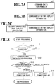
- FIG. 7A is a diagram for illustrating an example of command data for the printer to be transmitted by the information processing device 8 in the first embodiment.
- FIG. 7B is a diagram for illustrating an example of command data for the display apparatus at a time when the display apparatus is directly connected to the information processing device 8 in the first embodiment.
- FIG. 7C is a diagram for illustrating an example of command data for the display apparatus in a case where the display apparatus is connected to the information processing device 8 via the printer 1 in the first embodiment.
- FIG. 7A is a diagram for illustrating an example of the command data for the printer to be transmitted by the information processing device 8.
- the information processing device 8 transmits command data g11 for the printer to the printer 1 as command data as illustrated in FIG. 7A .
- header information for the printer is not assigned to the command data g11 for the printer.
- FIG. 7B is a diagram for illustrating an example of the command data for the display apparatus at a time when the display apparatus is directly connected to the information processing device 8.
- the information processing device 8 transmits command data g21 for the display apparatus to the display apparatus 7 as command data as illustrated in FIG. 7B .
- header information for the display apparatus is not assigned to the command data g21 for the display apparatus.
- FIG. 7C is a diagram for illustrating an example of the command data for the display apparatus in a case where the display apparatus is connected to the information processing device 8 via the printer 1.
- the information processing device 8 assigns header information g31 for the display apparatus to the command data g21 for the display apparatus as illustrated in FIG. 7C , and transmits the resultant data to the display apparatus 7 as command data.
- FIG. 8 is a flowchart for illustrating an example of the processing procedure of the communication initialization processing to be executed by the information processing device 8 in the first embodiment.
- Step S11 The processor 81 checks whether an apparatus (printer 1 or display apparatus 7) is connected to any one of the first driver 83 and the second driver 84. When it is determined that an apparatus is connected (Step S11: "YES"), the processor 81 advances the processing to Step S12. When it is determined that an apparatus is not connected (Step S11: “NO”), the processor 81 repeats the processing of Step S11.
- Step S12 The processor 81 and the connected apparatus execute the communication initialization processing, and the processor 81 acquires identification information on the apparatus.
- Step S13 The processor 81 determines whether the connected apparatus is the printer 1 or the display apparatus 7 based on the acquired identification information. When it is determined that the connected apparatus is the printer 1 (Step S13: “printer”), the processor 81 advances the processing to Step S14. When it is determined that the connected apparatus is the display apparatus 7 (Step S13: “display apparatus”), the processor 81 advances the processing to Step S15.
- Step S14 The processor 81 clears the direct connection flag, that is, sets the direct connection flag to "0", for example, and stores the direct connection flag into the storage 82. After the processing, the processor 81 ends the processing.
- Step S15 The processor 81 sets the direct connection flag to "1", for example, and stores the direct connection flag into the storage 82. After the processing, the processor 81 ends the processing.
- FIG. 9 is a flowchart for illustrating an example of the processing procedure of the communication initialization processing to be executed by the printer 1 according to the first embodiment.
- Step S21 When the communication initializer 11 is connected to the information processing device 8 via the connection cable 101, the communication initializer 11 executes the communication initialization processing.
- Step S22 The communication initializer 11 transmits printer information, which is identification information on the printer 1, to the information processing device 8 via the first communicator 12.
- FIG. 10 is a flowchart for illustrating an example of the processing procedure of the communication initialization processing to be executed by the display apparatus 7 in the first embodiment.
- Step S31 When the communication initializer 71 is connected to the information processing device 8 or the printer 1 via the connection cable 102, the communication initializer 71 executes the communication initialization processing.
- Step S32 When the communication initializer 71 is directly connected to the information processing device 8, the communication initializer 71 transmits display apparatus information, which is identification information on the display apparatus 7, to the information processing device 8 via the communicator 72. Alternatively, when the communication initializer 71 is directly connected to the printer 1, the communication initializer 71 transmits the display apparatus information to the printer 1 via the communicator 72.
- FIG. 11 is a flow chart for illustrating an example of a processing procedure of generating command data to be transmitted by the information processing device 8 to the display apparatus 7 after the communication initialization processing in the first embodiment.
- Step S41 The processor 81 generates command data for the display apparatus.
- Step S42 The processor 81 refers to the storage 82 to determine whether the direct connection flag is set or cleared. When it is determined that the direct connection flag is set (Step S42: “set”), the processor 81 outputs command data for the display apparatus to the display apparatus 7. When it is determined that the direct connection flag is cleared (Step S42: “cleared”), the processor 81 advances the processing to Step S43.
- Step S43 The processor 81 adds header information for the display apparatus to the command data for the display apparatus. After the processing, the processor 81 transmits the command data to the display apparatus 7 via the printer 1.
- FIG. 12 is a flowchart for illustrating an example of the processing procedure of the printer 1 at the time when the command data is received in the first embodiment.
- Step S51 The data analyzer 13 determines whether command data is received. When it is determined that command data is received (Step S51: "YES”), the data analyzer 13 advances the processing to Step S52. When it is determined that command data is not received (Step S51: "NO"), the data analyzer 13 repeats the processing of Step S51.
- Step S52 The data analyzer 13 determines whether header information for the display apparatus is added to the command data. When it is determined that header information for the display apparatus is added to the command data (Step S52: "YES”), the data analyzer 13 advances the processing to Step S53. When it is determined that header information for the display apparatus is not added to the command data (Step S52: "NO”), the data analyzer 13 advances the processing to Step S55.
- Step S53 The data analyzer 13 removes the header information for the display apparatus. After the processing, the data analyzer 13 advances the processing to Step S54.
- Step S54 The data analyzer 13 transmits command data from which the header information for the display apparatus is removed to the display apparatus 7 via the second communicator 16. After the processing, the data analyzer 13 ends the processing.
- Step S55 The data analyzer 13 outputs the command data to the controller 14.
- the controller 14 causes the printing unit 15 to execute printing based on the command data. After the processing, the controller 14 ends the processing.
- the direct connection flag is cleared.
- the information processing device 8 adds header information to command data for the display apparatus 7, and transmits the command data for the display apparatus to which the header information is added to the display apparatus 7 via the printer 1. Further, the information processing device 8 transmits the command data for the printer 1 to the printer 1 without adding header information to the command data. Then, when header information is not added to the received command data, the printer 1 determines that the received command data is command data for the printer, and executes printing processing. Further, when header information is added to the received command data, the printer 1 removes the header information, and transmits command information to the display apparatus 7. Then, the display apparatus 7 displays information on the display 77 ( FIG. 6 ) based on the received command information.
- the direct connection flag is set.
- the information processing device 8 transmits command data for the display apparatus 7 to the printer 1 without adding header information to the command data.
- the information processing device 8 transmits command data for the display apparatus 7 to the display apparatus 7 without adding header information to the command data.
- the printer 1 executes printing processing based on the received command data.
- the display apparatus 7 displays information on the display 77 based on the received command information. That is, the command data received by the display apparatus 7 does not include header information regardless of whether the display apparatus 7 is directly connected to the information processing device 8 or the display apparatus 7 is connected to the information processing device 8 via the printer 1.
- the printer 1 can extract header information for the display apparatus 7 from the command data received from the information processing device 8. Then, the printer 1 transmits to the display apparatus 7 command data from which the header information for the display apparatus 7 is removed, to thereby enable the display apparatus 7 to execute the same analysis processing as that for command data transmitted from the information processing device 8.
- the amount of command data received by the display apparatus 7 is smaller than when header information is added. Therefore, it is possible to manufacture the display apparatus 7 in the first embodiment with a circuit configuration that is less expensive than in an apparatus configuration in which header information is added.
- the apparatus to be connected to the information processing device 8 is not limited thereto.
- the apparatus to be connected to the information processing device 8 may be, for example, an input device (keyboard, touch panel sensor, and mouse) or a sound reproduction device (speaker).
- the sound reproduction device may receive command data including a digital signal from the information processing device 8, and reproduce a sound based on the received command data.
- the information processing device 8 may transmit command data to which header information for the sound generation device is added to the sound reproduction device via the printer 1. Then, the printer 1 can transmit command data from which header information is removed to the sound reproduction device, to thereby obtain an effect similar to that of the display apparatus 7 described above.
- the configurations of the information processing device 8, the printer 1, and the display apparatus 7 are similar to those of the first embodiment. Further, communication initialization processing of each of the printer 1 and the display apparatus 7 is similar to that of the first embodiment.
- FIG. 13 is a flowchart for illustrating an example of the processing procedure of the communication initialization processing to be executed by the information processing device 8 in the second embodiment.
- Step S11 and Step S12 The processor 81 executes the processing of Step S11 and Step S12.
- FIG. 14 is a flowchart for illustrating an example of the processing procedure of generating the command data to be transmitted by the information processing device 8 to the printer 1 after the communication initialization processing in the second embodiment.
- Step S61 The processor 81 generates command data for the printer and command data for the display apparatus.
- Step S62 The processor 81 determines whether the apparatus directly connected to the information processing device 8 is the printer 1 or the display apparatus 7 based on the acquired identification information. When it is determined that the printer 1 is connected (Step S62: “printer”), the processor 81 advances the processing to Step S63. When it is determined that the display apparatus 7 is connected (Step S62: “display apparatus”), the processor 81 advances the processing to Step S64.
- Step S63 The processor 81 adds header information for the printer to command data for the printer, and transmits to the printer 1 the command data for the printer to which the header information is added.
- the processor 81 transmits to the printer 1 the command data for the printer to which the header information is added, and the command data for the display apparatus to which the header information is not added. After the processing, the processor 81 ends the processing.
- Step S64 The processor 81 transmits to the display apparatus 7 command data for the display apparatus to which header information is not added without adding header information for the display apparatus to the command data for the display apparatus. After the processing, the processor 81 ends the processing.
- FIG. 15 is a flowchart for illustrating an example of the processing procedure of the printer 1 at the time when the command data is received in the second embodiment.
- Step S51 The data analyzer 13 executes processing similar to that of Step S51 ( FIG. 12 ). When it is determined that command data is received (Step S51: "YES”), the data analyzer 13 advances the processing to Step S71. When it is determined that command data is not received (Step S51: “NO”), the data analyzer 13 repeats the processing of Step S51.
- Step S71 The data analyzer 13 determines whether header information for the printer is added to the command data. When it is determined that header information for the printer is added to the command data (Step S71: "YES"), the data analyzer 13 advances the processing to Step S72. When it is determined that header information for the printer is not added to the command data (Step S71: "NO”), the data analyzer 13 advances the processing to Step S73.
- Step S72 The data analyzer 13 removes the header information for the printer. After the processing, the data analyzer 13 advances the processing to Step S55.
- Step S55 The data analyzer 13 executes processing similar to that of Step S55 ( FIG. 12 ). After the processing, the controller 14 ends the processing.
- Step S73 The data analyzer 13 transmits command data to which header information is not added to the display apparatus 7 via the second communicator 16. After the processing, the data analyzer 13 ends the processing.
- header information is not added to one apparatus, but added to the other apparatus.
- the information processing device 8 adds header information to command data for the printer 1, and transmits to the printer 1 command data for the printer to which the header information is added. Further, in the second embodiment, when the display apparatus 7 is connected to the information processing device 8 via the printer 1, the information processing device 8 transmits to the printer 1 command data for the printer to which header information is added, and command data for the display apparatus to which header information is not added. In this case, the printer 1 transmits to the display apparatus 7 command data for the display apparatus to which header information is not added. Further, in the second embodiment, when the display apparatus 7 is directly connected to the information processing device 8, the information processing device 8 does not add header information to command data for the display apparatus 7, and transmits to the display apparatus 7 command data for the display apparatus 7 to which header information is not added.
- command data received by the display apparatus 7 does not include header information regardless of whether the display apparatus 7 is directly connected to the information processing device 8 or the display apparatus 7 is connected to the information processing device 8 via the printer 1.
- the second embodiment it is possible to construct the circuit of the display apparatus 7 inexpensively similarly to the first embodiment.
- a program for implementing a part or all of the functions of the information processing device 8 and the printer 1 in at least one embodiment of the present invention may be recorded into a computer-readable recording medium, and the program recorded in this recording medium may be read into a computer system for execution, to thereby execute all or a part of the processing to be executed by the information processing device 8 and the printer 1.
- the "computer system” includes an OS or a piece of hardware, for example, a peripheral device.
- the "computer system” includes a WWW system having a webpage provision environment (or display environment).
- the term "computer-readable recording medium” refers to a portable medium such as a flexible disk, a magnetooptical disk, a ROM, or a CD-ROM, or a storage device, for example, a hard disk drive incorporated in the computer system. Further, it is assumed that the "computer-readable recording medium” includes a medium holding a program for a fixed period of time, for example, a volatile memory (RAM) inside the computer system serving as a server or a client in a case where a program is transmitted via a network, for example, the Internet, or a communication line, for example, a telephone line.
- RAM volatile memory
- the above-mentioned program may be transmitted from a computer system storing the program in a storage device, for example, to another computer system via a transmission medium or by a transmission wave in the transmission medium.
- the term "transmission medium" for transmitting the program refers to a medium having a function of transmitting information such as a network (communication network), for example, the Internet, or a communication line, for example, a telephone line.
- the above-mentioned program may be a program for implementing a part of the above-mentioned function.
- the above-mentioned program may be a so-called difference file (difference program) that can implement the above-mentioned function in cooperation with a program already stored in the computer system.
Landscapes
- Engineering & Computer Science (AREA)
- Theoretical Computer Science (AREA)
- General Engineering & Computer Science (AREA)
- Physics & Mathematics (AREA)
- General Physics & Mathematics (AREA)
- Human Computer Interaction (AREA)
- Computer Security & Cryptography (AREA)
- Computer Networks & Wireless Communication (AREA)
- Signal Processing (AREA)
- Accessory Devices And Overall Control Thereof (AREA)
- Facsimiles In General (AREA)
Abstract
Description
- The present invention relates to a printer system, a printer, a method of controlling a printer system, and a method of controlling a printer.
- In a point-of-sales (POS) system, a printer is connected to a host computer, for example. Further, in some POS systems, a display apparatus is connected to the POS system. The display apparatus is directly connected to the host computer or connected to the host computer via the printer.
- As such a display apparatus, there has been used a vacuum fluorescent display or a single-color liquid crystal display (LCD). In recent years, a display apparatus employing a high-definition color LCD has been required in order to cope with diversification of display content required for a customer display such as advertisement display, barcode display, or two-dimensional code display.
- When the display apparatus is connected via the printer, the printer is required to determine whether data received from the host computer is data addressed to the printer itself or data for the customer display, and transmit only the data for the customer display to the customer display. Thus, when the host computer transmits data to the display apparatus, it is required to add to transmission data header data indicating that the transmission data is data for the customer display.
- Further, when data received from the host computer and data received from the printer have different formats, the display apparatus is required to analyze which of the data formats the received data has, resulting in a loss of the processing capability of the host computer. Thus, in general, a common data format (e.g., format of adding header data indicating data for display apparatus) is employed regardless of whether the host computer directly transmits data or the printer transmits data.
- However, in the related art, when the display apparatus is connected to the host computer via the printer, the host computer transmits data to the printer and the display apparatus in a common data format. As a result, when the high-definition color LCD is employed as the display apparatus, the related art is required to execute high-speed communication because an amount of communication data becomes much larger than that required for a single-color LCD, for example, resulting in a problem in that the cost of the system is increased in order to execute the high-speed communication.
- In view of the above, in the field of this technology, there have been demanded a printer system, a printer, a method of controlling a printer system, and a method of controlling a printer, which are capable of reducing an amount of data addressed to a display apparatus.
- According to one embodiment of the present invention, there is provided a printer system, including: an information processing device; a printer; and a display apparatus, the information processing device being configured to control the printer and the display apparatus, wherein a topology of the information processing device and the display apparatus includes a first topology in which the display apparatus is directly connected to the information processing device and a second topology in which the display apparatus is connected to the information processing device via the printer, and wherein the information processing device includes a processor configured to: transmit, to the display apparatus, instruction data for the display apparatus without adding header information to the instruction data in the first topology; and transmit, to the printer, instruction data for the display apparatus by adding header information to the instruction data in the second topology.
- In the above-mentioned printer system according to the one embodiment, preferably the printer includes: two printer connection portions; and an analysis processor, and preferably the analysis processor of the printer is configured to: determine whether header information is added to instruction data when the information processing device is connected to a first printer connection portion of the two printer connection portions, the display apparatus is connected to a second printer connection portion of the two printer connection portions, and the analysis processor has received the instruction data from the information processing device; determine the instruction data to which the header information is added as the instruction data for the display apparatus; and transmit, to the display apparatus, the instruction data from which the header information is removed.
- According to one embodiment of the present invention, there is provided a printer, including: two printer connection portions; and an analysis processor, wherein the analysis processor is configured to: determine whether header information is added to instruction data when an information processing device configured to control the printer and a display apparatus is connected to a first printer connection portion of the two printer connection portions, the display apparatus is connected to a second printer connection portion of the two printer connection portions, and the analysis processor has received the instruction data from the information processing device; determine the instruction data to which the header information is added as instruction data for the display apparatus; and transmit, to the display apparatus, the instruction data from which the header information is removed.
- According to one embodiment of the present invention, there is provided a printer system, including: an information processing device; a printer; and a display apparatus, the information processing device being configured to control the printer and the display apparatus, wherein the information processing device includes: two connection portions; and a processor, wherein a topology of the printer and the display apparatus includes: a first topology in which the printer is connected to a first connection portion of the two connection portions; a second topology in which the display apparatus is connected to a second connection portion of the two connection portions; and a third connection topology in which the display apparatus is connected to one of the first connection portion and the second connection portion via the printer, and wherein the processor of the information processing device is configured to, in any of the first topology, the second topology, and the third topology: transmit, to the printer, instruction information to which header information is added; and transmit, to the display apparatus, instruction data without adding header information to the instruction data.
- In the above-mentioned printer system according to the one embodiment, preferably the printer includes: two printer connection portions; and an analysis processor, wherein the analysis processor of the printer is configured to: determine whether header information is added to instruction data when the information processing device is connected to a first printer connection portion of the two printer connection portions, the display apparatus is connected to a second printer connection portion of the two printer connection portions, and the analysis processor has received the instruction data from the information processing device; determine the instruction data to which the header information is added as instruction data for the printer, to thereby execute printing based on the instruction data from which the header information is removed; and determine the instruction data to which the header information is not added as instruction data for the display apparatus, to thereby transmit, to the display apparatus, the instruction data to which the header information is not added.
- According to one embodiment of the present invention, there is provided a printer, including: two printer connection portions; and an analysis processor, wherein the analysis processor is configured to: determine whether header information is added to instruction data when the information processing device configured to control the printer and a display apparatus is connected to a first printer connection portion of the two printer connection portions, the display apparatus is connected to a second printer connection portion of the two printer connection portions, and the analysis processor has received the instruction data from the information processing device; determine the instruction data to which the header information is added as instruction data for the printer, to thereby execute printing based on the instruction data from which the header information is removed; and determine the instruction data to which the header information is not added as instruction data for the display apparatus, to thereby transmit, to the display apparatus, the instruction data to which the header information is not added.
- According to one embodiment of the present invention, there is provided a method of controlling a printer system, the printer system including: an information processing device; a printer; and a display apparatus, the information processing device being configured to control the printer and the display apparatus, the information processing device including a processor, the printer including: two printer connection portions; and an analysis processor, a topology of the information processing device and the display apparatus including a first topology in which the display apparatus is directly connected to the information processing device and a second topology in which the display apparatus is connected to the information processing device via the printer, the method including: transmitting, to the display apparatus, by the processor of the information processing device, instruction data for the display apparatus without adding header information to the instruction data in the first topology; transmitting, to the printer, by the processor of the information processing device, instruction data for the display apparatus by adding header information to the instruction data in the second topology; determining, by the analysis processor of the printer, whether header information is added to instruction data when the information processing device is connected to a first printer connection portion of the two printer connection portions, the display apparatus is connected to a second printer connection portion of the two printer connection portions, and the analysis processor has received the instruction data from the information processing device; and determining, by the analysis processor of the printer, the instruction data to which the header information is added as the instruction data for the display apparatus, to thereby transmit, to the display apparatus, the instruction data from which the header information is removed.
- According to one embodiment of the present invention, there is provided a method of controlling a printer, the printer including: two printer connection portions; and an analysis processor, the method including: determining, by the analysis processor, whether header information is added to instruction data when an information processing device configured to control the printer and a display apparatus is connected to a first printer connection portion of the two printer connection portions, the display apparatus is connected to a second printer connection portion of the two printer connection portions, and the analysis processor has received the instruction data from the information processing device; and determining, by the analysis processor, the instruction data to which the header information is added as instruction data for the display apparatus, to thereby transmit, to the display apparatus, the instruction data from which the header information is removed.
- According to one embodiment of the present invention, there is provided a method of controlling a printer system, the printer system including: an information processing device; a printer; and a display apparatus, the information processing device being configured to control the printer and the display apparatus, the information processing device including: two connection portions; and a processor, the printer including: two printer connection portions; and an analysis processor, a topology of the printer and the display apparatus including: a first topology in which the printer is connected to a first connection portion of the two connection portions; a second topology in which the display apparatus is connected to a second connection portion of the two connection portions; and a third connection topology in which the display apparatus is connected to one of the first connection portion and the second connection portion via the printer, and the method including: transmitting, to the printer, by the processor of the information processing device, instruction information to which header information is added in any of the first topology, the second topology, and the third topology; transmitting, to the display apparatus, by the processor of the information processing device, instruction data without adding header information to the instruction data; determining, by the analysis processor of the printer, whether header information is added to instruction data when the information processing device is connected to a first printer connection portion of the two printer connection portions, the display apparatus is connected to a second printer connection portion of the two printer connection portions, and the analysis processor has received the instruction data from the information processing device; determining, by the analysis processor of the printer, the instruction data to which the header information is added as instruction data for the printer, to thereby execute printing based on the instruction data from which the header information is removed; and determining, by the analysis processor of the printer, the instruction data to which the header information is not added as instruction data for the display apparatus, to thereby transmit, to the display apparatus, the instruction data to which the header information is not added.
- According to one embodiment of the present invention, there is provided a method of controlling a printer, the printer including: two printer connection portions; and an analysis processor, the method including: determining, by the analysis processor, whether header information is added to instruction data when an information processing device configured to control the printer and a display apparatus is connected to a first printer connection portion of the two printer connection portions, the display apparatus is connected to a second printer connection portion of the two printer connection portions, and the analysis processor has received the instruction data from the information processing device; and
determining, by the analysis processor, the instruction data to which the header information is added as instruction data for the printer, to thereby execute printing based on the instruction data from which the header information is removed; and determining, by the analysis processor, the instruction data to which the header information is not added as instruction data for the display apparatus, to thereby transmit, to the display apparatus, the instruction data to which the header information is not added. - Embodiments of the present invention will now be described by way of further example only and with reference to the accompanying drawings, in which:
-
FIG. 1 is a perspective view of an appearance of a printer in a state in which a printer cover is closed in a first embodiment of the present invention. -
FIG. 2 is an exploded perspective view of the printer in a case where a display apparatus is connected to the printer according to the first embodiment. -
FIG. 3A is a diagram for illustrating an example of connection among an information processing device, the printer, and the display apparatus in the first embodiment. -
FIG. 3B is a diagram for illustrating an example of the connection among the information processing device, the printer, and the display apparatus according to the first embodiment. -
FIG. 4 is a block diagram for illustrating an exemplary configuration of the information processing device in the first embodiment. -
FIG. 5 is a block diagram for illustrating an exemplary configuration of the printer according to the first embodiment. -
FIG. 6 is a block diagram for illustrating an exemplary configuration of the display apparatus in the first embodiment. -
FIG. 7A is a diagram for illustrating an example of command data for the printer to be transmitted by the information processing device in the first embodiment. -
FIG. 7B is a diagram for illustrating an example of command data for the display apparatus at a time when the display apparatus is directly connected to the information processing device in the first embodiment. -
FIG. 7C is a diagram for illustrating an example of command data for the display apparatus in a case where the display apparatus is connected to the information processing device via the printer in the first embodiment. -
FIG. 8 is a flowchart for illustrating an example of a processing procedure of communication initialization processing to be executed by the information processing device in the first embodiment. -
FIG. 9 is a flowchart for illustrating an example of the processing procedure of the communication initialization processing to be executed by the printer according to the first embodiment. -
FIG. 10 is a flowchart for illustrating an example of the processing procedure of the communication initialization processing to be executed by the display apparatus in the first embodiment. -
FIG. 11 is a flowchart for illustrating an example of a processing procedure of generating command data to be transmitted by the information processing device to the display apparatus after the communication initialization processing in the first embodiment. -
FIG. 12 is a flowchart for illustrating an example of a processing procedure of the printer at a time when the command data is received in the first embodiment. -
FIG. 13 is a flowchart for illustrating an example of the processing procedure of the communication initialization processing to be executed by an information processing device in a second embodiment of the present invention. -
FIG. 14 is a flowchart for illustrating an example of the processing procedure of generating the command data to be transmitted by the information processing device to the printer after the communication initialization processing in the second embodiment. -
FIG. 15 is a flowchart for illustrating an example of the processing procedure of the printer at a time when the command data is received in the second embodiment. - Now, a description is given of at least one embodiment of the present invention with reference to the drawings. In the drawings referred to in the following description, the scale of each component is appropriately changed to set the size of the component recognizable.
-
FIG. 1 is a perspective view of an appearance of a printer in a state in which a printer cover is closed in a first embodiment of the present invention. InFIG. 1 and subsequent figures, an upper side of the drawing sheet is defined as an upward direction (upward direction in a gravity direction), and a lower side of the drawing sheet is defined as a downward direction (downward direction in the gravity direction). Further, a front-and-back direction is denoted by L1. An up-and-down direction is denoted by L2. A direction orthogonal to the front-and-back direction L1 and the up-and-down direction L2 is defined as a right-and-left direction L3. Further, a forward direction is indicated by the arrow FW, and a backward direction is indicated by the arrow BA. - As illustrated in
FIG. 1 , theprinter 1 is a printer of a so-called "forward delivery" type, in which a recording paper P is delivered in the forward direction (on afront surface 22 side of the printer 1). Theprinter 1 is used under a state in which the forward direction thereof is directed to, for example, a clerk, who is a first user, and the backward direction thereof is directed to, for example, a customer, who is a second user. This usage state of theprinter 1 is merely an example, and there is no particular limitation on the usage state. - The
printer 1 includes ahousing 2 and aprinter cover 3. Thehousing 2 is installed on aninstallation surface 110 of a counter of a store. Thehousing 2 has a plurality of outer surfaces including abottom surface 21, thefront surface 22, and aback surface 23. hebottom surface 21 is formed, in a large part, so as to be opposed to theinstallation surface 110 under a state of being separated therefrom. Thefront surface 22 is formed of theprinter cover 3 arranged in theopening 25. Theback surface 23 forms a mountingsurface 23A, on which a display apparatus 7 (seeFIG. 2 ) described later is removably mounted. The mountingsurface 23A is positioned on a side opposite to thefront surface 22. - The
printer cover 3 is coupled to a lower part of thehousing 2 so as to open and close theopening 25 of thehousing 2. A delivery slot 24 (gap) is formed between a distal end part of theprinter cover 3 and thehousing 2. The recording paper P is delivered in the forward direction from an inside of thehousing 2 through thedelivery slot 24. -
FIG. 2 is an exploded perspective view of the printer in a case where the display apparatus is connected to the printer according to the first embodiment. As illustrated inFIG. 2 , thedisplay apparatus 7 is removably mounted on the mountingsurface 23A of thehousing 2, for example. Thedisplay apparatus 7 includes a displaymain body 701 and adisplay mounting portion 702. - The display
main body 701 has a plate shape. One end of aconnection cable 102 is connected to the displaymain body 701. One end of aconnection cable 102 may be removably connected to the displaymain body 701, for example, through a connector (not shown). Adisplay 77 is provided on the displaymain body 701. Data such as payment information sent from theinformation processing device 8 are displayed on thedisplay 77 in the forms of characters and images. - The
display mounting portion 702 has a plate shape. Thedisplay mounting portion 702 is mounted on the mountingsurface 23A of thehousing 2. An upper part of thedisplay mounting portion 702 is pivotably mounted on an upper part of the displaymain body 701 through intermediation ofpivot portions 704 formed of, for example, hinges. With thepivot portions 704, thedisplay 77 of the displaymain body 701 can be changed in angle with respect to the mountingsurface 23A. - A
display arrangement portion 26 is formed so as to be recessed in the mountingsurface 23A of thehousing 2. Thedisplay mounting portion 702 is arranged in thedisplay arrangement portion 26. The movement of a lower part of thedisplay mounting portion 702 is regulated by holding the lower part of thedisplay mounting portion 702 in abutment against astep portion 29 on a lower side of thedisplay arrangement portion 26. - A pair of sandwiching
portions edge portions display arrangement portion 26. The pair of sandwichingportions display mounting portion 702 are sandwiched by the pair of sandwichingportions display mounting portion 702 are sandwiched by the pair of sandwichingportions printer 1 illustrated inFIG. 1 andFIG. 2 is only one example, and the shape of theprinter 1 is not limited to this example. Further, the shape of thedisplay apparatus 7 illustrated inFIG. 2 is only one example, and the shape of thedisplay apparatus 7 is not limited to this example. - Next, a description is given of an example of connection among the
information processing device 8, theprinter 1, and thedisplay apparatus 7.FIG. 3A and FIG. 3B are diagrams for illustrating examples of connection among theinformation processing device 8, theprinter 1, and thedisplay apparatus 7 in the first embodiment. A system including theinformation processing device 8, theprinter 1, and thedisplay apparatus 7 is used for a point-of-sales (POS) system, for example. The POS system is installed at a store such as a retail store or a restaurant. The POS system is a system for notifying a customer of payment information (predetermined information) such as the name and price of a product purchased by the customer. - The
information processing device 8 includes aprocessor 81 configured to execute payment processing for a product, for example. Theinformation processing device 8 is configured to control operations of theprinter 1 and thedisplay apparatus 7. Theinformation processing device 8 is a personal computer, for example. Theprinter 1 is a thermal printer, for example, and is installed at a counter of a store, for example. Thedisplay apparatus 7 is a liquid crystal display apparatus or an organic electroluminescence (EL) display apparatus, for example. -
FIG. 3A is a diagram for illustrating an example of a configuration in which theprinter 1 is connected to theinformation processing device 8 via aconnection cable 101, and thedisplay apparatus 7 is connected to theprinter 1 via theconnection cable 102. In the example illustrated inFIG. 3A , theprinter 1 is directly connected to theinformation processing device 8, and thedisplay apparatus 7 is connected to theinformation processing device 8 via theprinter 1. -
FIG. 3B is a diagram for illustrating an example of a configuration in which theprinter 1 is connected to theinformation processing device 8 via theconnection cable 101, and thedisplay apparatus 7 is connected to theinformation processing device 8 via theconnection cable 102. In the example illustrated inFIG. 3B , theprinter 1 is directly connected to theinformation processing device 8, and thedisplay apparatus 7 is also directly connected to theinformation processing device 8. - Next, a description is given of an exemplary configuration of the
information processing device 8.FIG. 4 is a block diagram for illustrating an exemplary configuration of theinformation processing device 8 in the first embodiment. As illustrated inFIG. 4 , theinformation processing device 8 includes theprocessor 81, astorage 82, a first driver 83 (first connection portion), and a second driver 84 (second connection portion). - The
processor 81 communicates to/from apparatus connected thereto (printer 1 (FIG. 3A and FIG. 3B ) and display apparatus 7 (FIG. 3A and FIG. 3B )) to acquire identification information on each of the apparatus. Theprocessor 81 adds header information to command data (instruction data) to be transmitted depending on the connected apparatus. Theprocessor 81 outputs the command data to one of thefirst driver 83 and thesecond driver 84 to which the apparatus is connected. When an apparatus is connected to thefirst driver 83 or thesecond driver 84, theprocessor 81 executes communication initialization processing to acquire identification information on the apparatus. Theprocessor 81 determines whether the connected apparatus is theprinter 1 or thedisplay apparatus 7 based on the acquired identification information, and sets a direct connection flag. Theprocessor 81 stores the set direct connection flag into thestorage 82. When the connection method is a universal serial bus (USB) standard, the communication initialization processing is negotiation processing to be executed when theprinter 1 or thedisplay apparatus 7 is connected to theinformation processing device 8 via a connection cable (USB cable). - The
storage 82 stores identification information on the apparatus (printer 1 and display apparatus 7). Thestorage 82 stores header information to be added to the command data of thedisplay apparatus 7. Further, thestorage 82 stores the direct connection flag. - The
first driver 83 acquires identification information on an apparatus by communicating to/from the apparatus when the apparatus is connected, in accordance with control by theprocessor 81. Thefirst driver 83 transmits command data output by theprocessor 81 to the connected apparatus. - The
second driver 84 acquires identification information on an apparatus by communicating to/from the apparatus when the apparatus is connected, in accordance with control by theprocessor 81. Thesecond driver 84 transmits command data output by theprocessor 81 to the connected apparatus. - Next, a description is given of an exemplary configuration of the
printer 1.FIG. 5 is a block diagram for illustrating an exemplary configuration of theprinter 1 according to the first embodiment. As illustrated inFIG. 5 , theprinter 1 includes acommunication initializer 11, a first communicator 12 (first printer connection portion), a data analyzer 13 (analysis processor), a controller 14 (analysis processor), a printing unit 15 (analysis processor), and a second communicator 16 (second printer connection portion). - As described with reference to
FIG. 3A and FIG. 3B , theprinter 1 is connected to, for example, thefirst driver 83 of theinformation processing device 8 via the connection cable 101 (FIG. 3A and FIG. 3B ). Further, thedisplay apparatus 7 may be connected to theprinter 1 via the connection cable 102 (FIG. 3A and FIG. 3B ). Theinformation processing device 8 is connected to thefirst communicator 12 via theconnection cable 101. Further, thedisplay apparatus 7 is connected to thesecond communicator 16 via theconnection cable 102. - The
communication initializer 11 executes communication initialization processing to be executed at a time of establishment of connection to theinformation processing device 8. Thecommunication initializer 11 stores identification information (printer information) on theprinter 1. - The
first communicator 12 executes negotiation by acquiring data from and outputting data to theinformation processing device 8 when thefirst communicator 12 is connected to theinformation processing device 8 via the connection cable 101 (FIG. 3A and FIG. 3B ). At the time of negotiation, thefirst communicator 12 transmits printer information to theinformation processing device 8. Further, after the communication initialization processing, thefirst communicator 12 acquires command data from theinformation processing device 8, and outputs the acquired data to thedata analyzer 13. - The data analyzer 13 acquires the command data output by the
first communicator 12, and determines whether header information for thedisplay apparatus 7 is included in the acquired command data. When header information for thedisplay apparatus 7 is not included in the command data, thedata analyzer 13 outputs the command data to thecontroller 14. When thedisplay apparatus 7 is connected to thesecond communicator 16 via theconnection cable 102, thedata analyzer 13 acquires display apparatus information, which is identification information on thedisplay apparatus 7 and is output by thesecond communicator 16. When header information for thedisplay apparatus 7 is included in the command data, thedata analyzer 13 outputs to thesecond communicator 16 command data from which the header information for thedisplay apparatus 7 is removed. - The
controller 14 generates print data based on the command data output by thedata analyzer 13. Thecontroller 14 outputs the generated print data to theprinting unit 15. Theprinting unit 15 prints the print data generated by thecontroller 14. - When the
display apparatus 7 is connected to thesecond communicator 16 via the connection cable 102 (FIG. 3A and FIG. 3B ), thesecond communicator 16 executes negotiation by acquiring data from and outputting data to thedisplay apparatus 7. At the time of negotiation, thesecond communicator 16 acquires display apparatus information, and outputs the acquired display apparatus information to thedata analyzer 13. Further, after the negotiation, thesecond communicator 16 transmits the command data output by thedata analyzer 13 to thedisplay apparatus 7. - Specifically, when the
display apparatus 7 is connected to theprinter 1, theprinter 1 transmits to theinformation processing device 8 the display apparatus information, which is identification information on thedisplay apparatus 7 acquired through negotiation between theprinter 1 and thedisplay apparatus 7. Theinformation processing device 8 determines whether only theprinter 1 is connected or thedisplay apparatus 7 is connected via theprinter 1 based on the information received from theprinter 1 in this manner. - Next, a description is given of an exemplary configuration of the
display apparatus 7.FIG. 6 is a block diagram for illustrating an exemplary configuration of thedisplay apparatus 7 in the first embodiment. As illustrated inFIG. 6 , thedisplay apparatus 7 includes acommunication initializer 71, acommunicator 72, adata analyzer 73, astorage 74, adisplay data generator 75, adisplay controller 76, and adisplay 77. - As described with reference to
FIG. 3A and FIG. 3B , thedisplay apparatus 7 is connected to, for example, thesecond driver 84 of theinformation processing device 8 via the connection cable 102 (FIG. 3A and FIG. 3B ). Alternatively, thedisplay apparatus 7 is connected to thesecond communicator 16 of theprinter 1 via theconnection cable 102. - The
communication initializer 71 executes communication initialization processing to be executed at a time of establishment of connection to theinformation processing device 8 or theprinter 1. Thecommunication initializer 71 stores display apparatus information on theprinter 1. - The
communicator 72 executes negotiation by acquiring data from and outputting data to theinformation processing device 8 when thecommunicator 72 is connected to theinformation processing device 8 via the connection cable 102 (FIG. 3A and FIG. 3B ). At the time of negotiation, thecommunicator 72 transmits display apparatus information to theinformation processing device 8. Further, after the communication initialization processing, thecommunicator 72 acquires command data from theinformation processing device 8, and outputs the acquired data to thedata analyzer 73. When thecommunicator 72 is connected to theprinter 1 via the connection cable 102 (FIG. 3A and FIG. 3B ), thecommunicator 72 executes negotiation by acquiring data from and outputting data to theprinter 1. At the time of negotiation, thecommunicator 72 transmits display apparatus information to theprinter 1. Further, after the communication initialization processing, thecommunicator 72 acquires command data from theprinter 1, and outputs the acquired command data to thedata analyzer 73. - The data analyzer 73 analyzes the command data output by the
communicator 72, and stores the analyzed command data into thestorage 74. The data analyzer 73 divides the command data into setting information, font information, image information, and the other function information, for example, to store the information into thestorage 74. The data analyzer 73 outputs an analysis result obtained by analysis to thedisplay data generator 75. - The
storage 74 includes a plurality of storage regions, for example. For example, thestorage 74 stores the setting information into a first storage region, stores the font information into a second storage region, stores the image information into a third storage region, and stores the other function information into a fourth storage region. - The
display data generator 75 reads the setting information, font information, image information, and other function information stored in thestorage 74, based on the analysis result output by thedata analyzer 73. Thedisplay data generator 75 generates display data based on the read setting information, font information, image information, and other function information, and outputs the generated display data to thedisplay controller 76. - The
display controller 76 displays information on thedisplay 77 based on the display data output by thedisplay data generator 75. - The
display 77 is a color liquid crystal display (LCD), for example. - Next, a description is given of an example of command data to be transmitted by the
information processing device 8.FIG. 7A is a diagram for illustrating an example of command data for the printer to be transmitted by theinformation processing device 8 in the first embodiment.FIG. 7B is a diagram for illustrating an example of command data for the display apparatus at a time when the display apparatus is directly connected to theinformation processing device 8 in the first embodiment.FIG. 7C is a diagram for illustrating an example of command data for the display apparatus in a case where the display apparatus is connected to theinformation processing device 8 via theprinter 1 in the first embodiment. -
FIG. 7A is a diagram for illustrating an example of the command data for the printer to be transmitted by theinformation processing device 8. When theprinter 1 is connected to theinformation processing device 8, theinformation processing device 8 transmits command data g11 for the printer to theprinter 1 as command data as illustrated inFIG. 7A . As illustrated inFIG. 7A , header information for the printer is not assigned to the command data g11 for the printer. -
FIG. 7B is a diagram for illustrating an example of the command data for the display apparatus at a time when the display apparatus is directly connected to theinformation processing device 8. When thedisplay apparatus 7 is directly connected to theinformation processing device 8, theinformation processing device 8 transmits command data g21 for the display apparatus to thedisplay apparatus 7 as command data as illustrated inFIG. 7B . As illustrated inFIG. 7B , header information for the display apparatus is not assigned to the command data g21 for the display apparatus. -
FIG. 7C is a diagram for illustrating an example of the command data for the display apparatus in a case where the display apparatus is connected to theinformation processing device 8 via theprinter 1. When thedisplay apparatus 7 is connected to theinformation processing device 8 via theprinter 1, theinformation processing device 8 assigns header information g31 for the display apparatus to the command data g21 for the display apparatus as illustrated inFIG. 7C , and transmits the resultant data to thedisplay apparatus 7 as command data. - Now, a description is given of an example of a processing procedure of the communication initialization processing to be executed by the
information processing device 8.FIG. 8 is a flowchart for illustrating an example of the processing procedure of the communication initialization processing to be executed by theinformation processing device 8 in the first embodiment. - (Step S11) The
processor 81 checks whether an apparatus (printer 1 or display apparatus 7) is connected to any one of thefirst driver 83 and thesecond driver 84. When it is determined that an apparatus is connected (Step S11: "YES"), theprocessor 81 advances the processing to Step S12. When it is determined that an apparatus is not connected (Step S11: "NO"), theprocessor 81 repeats the processing of Step S11. - (Step S12) The
processor 81 and the connected apparatus execute the communication initialization processing, and theprocessor 81 acquires identification information on the apparatus. - (Step S13) The
processor 81 determines whether the connected apparatus is theprinter 1 or thedisplay apparatus 7 based on the acquired identification information. When it is determined that the connected apparatus is the printer 1 (Step S13: "printer"), theprocessor 81 advances the processing to Step S14. When it is determined that the connected apparatus is the display apparatus 7 (Step S13: "display apparatus"), theprocessor 81 advances the processing to Step S15. - (Step S14) The
processor 81 clears the direct connection flag, that is, sets the direct connection flag to "0", for example, and stores the direct connection flag into thestorage 82. After the processing, theprocessor 81 ends the processing. - (Step S15) The
processor 81 sets the direct connection flag to "1", for example, and stores the direct connection flag into thestorage 82. After the processing, theprocessor 81 ends the processing. - Next, a description is given of an example of the processing procedure to be executed by the
printer 1 at the time of the communication initialization processing.FIG. 9 is a flowchart for illustrating an example of the processing procedure of the communication initialization processing to be executed by theprinter 1 according to the first embodiment. - (Step S21) When the
communication initializer 11 is connected to theinformation processing device 8 via theconnection cable 101, thecommunication initializer 11 executes the communication initialization processing. - (Step S22) The
communication initializer 11 transmits printer information, which is identification information on theprinter 1, to theinformation processing device 8 via thefirst communicator 12. - Next, a description is given of an example of the processing procedure to be executed by the
display apparatus 7 at the time of the communication initialization processing.FIG. 10 is a flowchart for illustrating an example of the processing procedure of the communication initialization processing to be executed by thedisplay apparatus 7 in the first embodiment. - (Step S31) When the
communication initializer 71 is connected to theinformation processing device 8 or theprinter 1 via theconnection cable 102, thecommunication initializer 71 executes the communication initialization processing. - (Step S32) When the
communication initializer 71 is directly connected to theinformation processing device 8, thecommunication initializer 71 transmits display apparatus information, which is identification information on thedisplay apparatus 7, to theinformation processing device 8 via thecommunicator 72. Alternatively, when thecommunication initializer 71 is directly connected to theprinter 1, thecommunication initializer 71 transmits the display apparatus information to theprinter 1 via thecommunicator 72. - Next, a description is given of an example of a processing procedure of generating command data to be transmitted by the
information processing device 8 to thedisplay apparatus 7 after the communication initialization processing.FIG. 11 is a flow chart for illustrating an example of a processing procedure of generating command data to be transmitted by theinformation processing device 8 to thedisplay apparatus 7 after the communication initialization processing in the first embodiment. - (Step S41) The
processor 81 generates command data for the display apparatus. - (Step S42) The
processor 81 refers to thestorage 82 to determine whether the direct connection flag is set or cleared. When it is determined that the direct connection flag is set (Step S42: "set"), theprocessor 81 outputs command data for the display apparatus to thedisplay apparatus 7. When it is determined that the direct connection flag is cleared (Step S42: "cleared"), theprocessor 81 advances the processing to Step S43. - (Step S43) The
processor 81 adds header information for the display apparatus to the command data for the display apparatus. After the processing, theprocessor 81 transmits the command data to thedisplay apparatus 7 via theprinter 1. - Next, a description is given of an example of a processing procedure of the
printer 1 at a time when command data is received.FIG. 12 is a flowchart for illustrating an example of the processing procedure of theprinter 1 at the time when the command data is received in the first embodiment. - (Step S51) The data analyzer 13 determines whether command data is received. When it is determined that command data is received (Step S51: "YES"), the data analyzer 13 advances the processing to Step S52. When it is determined that command data is not received (Step S51: "NO"), the
data analyzer 13 repeats the processing of Step S51. - (Step S52) The data analyzer 13 determines whether header information for the display apparatus is added to the command data. When it is determined that header information for the display apparatus is added to the command data (Step S52: "YES"), the data analyzer 13 advances the processing to Step S53. When it is determined that header information for the display apparatus is not added to the command data (Step S52: "NO"), the data analyzer 13 advances the processing to Step S55.
- (Step S53) The data analyzer 13 removes the header information for the display apparatus. After the processing, the data analyzer 13 advances the processing to Step S54.
- (Step S54) The data analyzer 13 transmits command data from which the header information for the display apparatus is removed to the
display apparatus 7 via thesecond communicator 16. After the processing, thedata analyzer 13 ends the processing. - (Step S55) The data analyzer 13 outputs the command data to the
controller 14. Next, thecontroller 14 causes theprinting unit 15 to execute printing based on the command data. After the processing, thecontroller 14 ends the processing. - As described above, in the first embodiment, when the
display apparatus 7 is connected to theinformation processing device 8 via theprinter 1, the direct connection flag is cleared. As a result, theinformation processing device 8 adds header information to command data for thedisplay apparatus 7, and transmits the command data for the display apparatus to which the header information is added to thedisplay apparatus 7 via theprinter 1. Further, theinformation processing device 8 transmits the command data for theprinter 1 to theprinter 1 without adding header information to the command data. Then, when header information is not added to the received command data, theprinter 1 determines that the received command data is command data for the printer, and executes printing processing. Further, when header information is added to the received command data, theprinter 1 removes the header information, and transmits command information to thedisplay apparatus 7. Then, thedisplay apparatus 7 displays information on the display 77 (FIG. 6 ) based on the received command information. - Further, in the first embodiment, when the
printer 1 is directly connected to theinformation processing device 8 and thedisplay apparatus 7 is directly connected to theinformation processing device 8, the direct connection flag is set. As a result, theinformation processing device 8 transmits command data for thedisplay apparatus 7 to theprinter 1 without adding header information to the command data. Theinformation processing device 8 transmits command data for thedisplay apparatus 7 to thedisplay apparatus 7 without adding header information to the command data. Then, theprinter 1 executes printing processing based on the received command data. Further, thedisplay apparatus 7 displays information on thedisplay 77 based on the received command information. That is, the command data received by thedisplay apparatus 7 does not include header information regardless of whether thedisplay apparatus 7 is directly connected to theinformation processing device 8 or thedisplay apparatus 7 is connected to theinformation processing device 8 via theprinter 1. - As a result, according to the first embodiment, the
printer 1 can extract header information for thedisplay apparatus 7 from the command data received from theinformation processing device 8. Then, theprinter 1 transmits to thedisplay apparatus 7 command data from which the header information for thedisplay apparatus 7 is removed, to thereby enable thedisplay apparatus 7 to execute the same analysis processing as that for command data transmitted from theinformation processing device 8. As a result, according to the first embodiment, the amount of command data received by thedisplay apparatus 7 is smaller than when header information is added. Therefore, it is possible to manufacture thedisplay apparatus 7 in the first embodiment with a circuit configuration that is less expensive than in an apparatus configuration in which header information is added. - In the above-mentioned example and in subsequent examples and embodiments, a description is given of an example of the
printer 1 and thedisplay apparatus 7 as an example of an apparatus to be connected to theinformation processing device 8. However, the apparatus to be connected to theinformation processing device 8 is not limited thereto. The apparatus to be connected to theinformation processing device 8 may be, for example, an input device (keyboard, touch panel sensor, and mouse) or a sound reproduction device (speaker). In this case, the sound reproduction device may receive command data including a digital signal from theinformation processing device 8, and reproduce a sound based on the received command data. Then, when the sound reproduction device is connected via theprinter 1, for example, in this manner, theinformation processing device 8 may transmit command data to which header information for the sound generation device is added to the sound reproduction device via theprinter 1. Then, theprinter 1 can transmit command data from which header information is removed to the sound reproduction device, to thereby obtain an effect similar to that of thedisplay apparatus 7 described above. - In the first embodiment, a description has been given of an example in which the
information processing device 8 adds or does not add header information depending on a topology of thedisplay apparatus 7. In a second embodiment of the present invention, a description is given of an example in which header information is added to command data to be transmitted to theprinter 1 and header information is not added to command data to be transmitted to thedisplay apparatus 7. - The configurations of the
information processing device 8, theprinter 1, and thedisplay apparatus 7 are similar to those of the first embodiment. Further, communication initialization processing of each of theprinter 1 and thedisplay apparatus 7 is similar to that of the first embodiment. - First, a description is given of an example of a processing procedure of communication initialization processing to be executed by the
information processing device 8.FIG. 13 is a flowchart for illustrating an example of the processing procedure of the communication initialization processing to be executed by theinformation processing device 8 in the second embodiment. - (Step S11 and Step S12) The
processor 81 executes the processing of Step S11 and Step S12. - Next, a description is given of an example of a processing procedure of generating command data to be transmitted by the
information processing device 8 to theprinter 1 after the communication initialization processing.FIG. 14 is a flowchart for illustrating an example of the processing procedure of generating the command data to be transmitted by theinformation processing device 8 to theprinter 1 after the communication initialization processing in the second embodiment. - (Step S61) The
processor 81 generates command data for the printer and command data for the display apparatus. - (Step S62) The
processor 81 determines whether the apparatus directly connected to theinformation processing device 8 is theprinter 1 or thedisplay apparatus 7 based on the acquired identification information. When it is determined that theprinter 1 is connected (Step S62: "printer"), theprocessor 81 advances the processing to Step S63. When it is determined that thedisplay apparatus 7 is connected (Step S62: "display apparatus"), theprocessor 81 advances the processing to Step S64. - (Step S63) The
processor 81 adds header information for the printer to command data for the printer, and transmits to theprinter 1 the command data for the printer to which the header information is added. When thedisplay apparatus 7 is connected via theprinter 1, theprocessor 81 transmits to theprinter 1 the command data for the printer to which the header information is added, and the command data for the display apparatus to which the header information is not added. After the processing, theprocessor 81 ends the processing. - (Step S64) The
processor 81 transmits to thedisplay apparatus 7 command data for the display apparatus to which header information is not added without adding header information for the display apparatus to the command data for the display apparatus. After the processing, theprocessor 81 ends the processing. - Next, a description is given of an example of a processing procedure of the
printer 1 at a time when command data is received.FIG. 15 is a flowchart for illustrating an example of the processing procedure of theprinter 1 at the time when the command data is received in the second embodiment. - (Step S51) The data analyzer 13 executes processing similar to that of Step S51 (
FIG. 12 ). When it is determined that command data is received (Step S51: "YES"), the data analyzer 13 advances the processing to Step S71. When it is determined that command data is not received (Step S51: "NO"), thedata analyzer 13 repeats the processing of Step S51. - (Step S71) The data analyzer 13 determines whether header information for the printer is added to the command data. When it is determined that header information for the printer is added to the command data (Step S71: "YES"), the data analyzer 13 advances the processing to Step S72. When it is determined that header information for the printer is not added to the command data (Step S71: "NO"), the data analyzer 13 advances the processing to Step S73.
- (Step S72) The data analyzer 13 removes the header information for the printer. After the processing, the data analyzer 13 advances the processing to Step S55.
- (Step S55) The data analyzer 13 executes processing similar to that of Step S55 (
FIG. 12 ). After the processing, thecontroller 14 ends the processing. - (Step S73) The data analyzer 13 transmits command data to which header information is not added to the
display apparatus 7 via thesecond communicator 16. After the processing, thedata analyzer 13 ends the processing. - In this manner, in the second embodiment, when two apparatus are connected to the
information processing device 8, header information is not added to one apparatus, but added to the other apparatus. - As described above, in the second embodiment, the
information processing device 8 adds header information to command data for theprinter 1, and transmits to theprinter 1 command data for the printer to which the header information is added. Further, in the second embodiment, when thedisplay apparatus 7 is connected to theinformation processing device 8 via theprinter 1, theinformation processing device 8 transmits to theprinter 1 command data for the printer to which header information is added, and command data for the display apparatus to which header information is not added. In this case, theprinter 1 transmits to thedisplay apparatus 7 command data for the display apparatus to which header information is not added. Further, in the second embodiment, when thedisplay apparatus 7 is directly connected to theinformation processing device 8, theinformation processing device 8 does not add header information to command data for thedisplay apparatus 7, and transmits to thedisplay apparatus 7 command data for thedisplay apparatus 7 to which header information is not added. - Also in this case, command data received by the
display apparatus 7 does not include header information regardless of whether thedisplay apparatus 7 is directly connected to theinformation processing device 8 or thedisplay apparatus 7 is connected to theinformation processing device 8 via theprinter 1. As a result, according to the second embodiment as well, it is possible to construct the circuit of thedisplay apparatus 7 inexpensively similarly to the first embodiment. - A program for implementing a part or all of the functions of the
information processing device 8 and theprinter 1 in at least one embodiment of the present invention may be recorded into a computer-readable recording medium, and the program recorded in this recording medium may be read into a computer system for execution, to thereby execute all or a part of the processing to be executed by theinformation processing device 8 and theprinter 1. It is assumed that the "computer system" includes an OS or a piece of hardware, for example, a peripheral device. Further, it is assumed that the "computer system" includes a WWW system having a webpage provision environment (or display environment). Further, the term "computer-readable recording medium" refers to a portable medium such as a flexible disk, a magnetooptical disk, a ROM, or a CD-ROM, or a storage device, for example, a hard disk drive incorporated in the computer system. Further, it is assumed that the "computer-readable recording medium" includes a medium holding a program for a fixed period of time, for example, a volatile memory (RAM) inside the computer system serving as a server or a client in a case where a program is transmitted via a network, for example, the Internet, or a communication line, for example, a telephone line. - Further, the above-mentioned program may be transmitted from a computer system storing the program in a storage device, for example, to another computer system via a transmission medium or by a transmission wave in the transmission medium. The term "transmission medium" for transmitting the program refers to a medium having a function of transmitting information such as a network (communication network), for example, the Internet, or a communication line, for example, a telephone line. Further, the above-mentioned program may be a program for implementing a part of the above-mentioned function. Further, the above-mentioned program may be a so-called difference file (difference program) that can implement the above-mentioned function in cooperation with a program already stored in the computer system.
- This concludes the descriptions of the embodiments as modes for carrying out the present invention. However, the present invention is not limited to the embodiments in any way, and various modifications and substitutions can be made within the scope of the present invention.
Claims (10)
- A printer system, comprising:an information processing device (8);a printer (1); anda display apparatus (7),the information processing device (8) being configured to control the printer (1) and the display apparatus (7),wherein a topology of the information processing device (8) and the display apparatus (7) includes a first topology in which the display apparatus (7) is directly connected to the information processing device (8) and a second topology in which the display apparatus (7) is connected to the information processing device (8) via the printer (1), andwherein the information processing device (8) includes a processor (81) configured to:transmit, to the display apparatus (7), instruction data for the display apparatus (7) without adding header information to the instruction data in the first topology; andtransmit, to the printer (1), instruction data for the display apparatus (7) by adding header information to the instruction data in the second topology.
- The printer system according to claim 1,
wherein the printer (1) includes:two printer connection portions (12, 16); andan analysis processor (13, 14, 15), andwherein the analysis processor (13, 14, 15) of the printer (1) is configured to:determine whether header information is added to instruction data when the information processing device (8) is connected to a first printer connection portion (12) of the two printer connection portions (12, 16), the display apparatus (7) is connected to a second printer connection portion (16) of the two printer connection portions (12, 16), and the analysis processor (13, 14, 15) has received the instruction data from the information processing device (8);determine the instruction data to which the header information is added as the instruction data for the display apparatus (7); andtransmit, to the display apparatus (7), the instruction data from which the header information is removed. - A printer (1), comprising:two printer connection portions (12, 16); andan analysis processor (13, 14, 15),wherein the analysis processor (13, 14, 15) is configured to:determine whether header information is added to instruction data when an information processing device (8) configured to control the printer (1) and a display apparatus (7) is connected to a first printer connection portion (12) of the two printer connection portions (12, 16), the display apparatus (7) is connected to a second printer connection portion (16) of the two printer connection portions (12, 16), and the analysis processor (13, 14, 15) has received the instruction data from the information processing device (8);determine the instruction data to which the header information is added as instruction data for the display apparatus (7); andtransmit, to the display apparatus (7), the instruction data from which the header information is removed.
- A printer system, comprising:an information processing device (8);a printer (1); anda display apparatus (7),the information processing device (8) being configured to control the printer (1) and the display apparatus (7),wherein the information processing device (8) includes:two connection portions (83, 84); anda processor (81),wherein a topology of the printer (1) and the display apparatus (7) includes: a first topology in which the printer (1) is connected to a first connection portion (83) of the two connection portions (83, 84); a second topology in which the display apparatus (7) is connected to a second connection portion (84) of the two connection portions (83, 84); and a third connection topology in which the display apparatus (7) is connected to one of the first connection portion (83) and the second connection portion (84) via the printer (1), andwherein the processor (81) of the information processing device (8) is configured to, in any of the first topology, the second topology, and the third topology:transmit, to the printer (1), instruction information to which header information is added; andtransmit, to the display apparatus (7), instruction data without adding header information to the instruction data.
- The printer system according to claim 4,
wherein the printer (1) includes:two printer connection portions (12, 16); andan analysis processor (13, 14, 15),wherein the analysis processor (13, 14, 15) of the printer (1) is configured to:determine whether header information is added to instruction data when the information processing device (8) is connected to a first printer connection portion (12) of the two printer connection portions (12, 16), the display apparatus (7) is connected to a second printer connection portion (16) of the two printer connection portions (12, 16), and the analysis processor (13, 14, 15) has received the instruction data from the information processing device (8);determine the instruction data to which the header information is added as instruction data for the printer (1), to thereby execute printing based on the instruction data from which the header information is removed; anddetermine the instruction data to which the header information is not added as instruction data for the display apparatus (7), to thereby transmit, to the display apparatus (7), the instruction data to which the header information is not added. - A printer (1), comprising:two printer connection portions (12, 16); andan analysis processor (13, 14, 15),wherein the analysis processor (13, 14, 15) is configured to:determine whether header information is added to instruction data when an information processing device (8) configured to control the printer (1) and a display apparatus (7) is connected to a first printer connection portion (12) of the two printer connection portions (12, 16), the display apparatus (7) is connected to a second printer connection portion (16) of the two printer connection portions (12, 16), and the analysis processor (13, 14, 15) has received the instruction data from the information processing device (8);determine the instruction data to which the header information is added as instruction data for the printer (1), to thereby execute printing based on the instruction data from which the header information is removed; anddetermine the instruction data to which the header information is not added as instruction data for the display apparatus (7), to thereby transmit, to the display apparatus (7), the instruction data to which the header information is not added.
- A method of controlling a printer system,
the printer system including:an information processing device (8);a printer (1); anda display apparatus (7),the information processing device (8) being configured to control the printer (1) and the display apparatus (7),the information processing device (8) including a processor (81),the printer (1) including:a topology of the information processing device (8) and the display apparatus (7) including a first topology in which the display apparatus (7) is directly connected to the information processing device (8) and a second topology in which the display apparatus (7) is connected to the information processing device (8) via the printer (1),two printer connection portions (12, 16); andan analysis processor (13, 14, 15),
the method comprising:transmitting, to the display apparatus (7), by the processor (81) of the information processing device (8), instruction data for the display apparatus (7) without adding header information to the instruction data in the first topology;transmitting, to the printer (1), by the processor (81) of the information processing device (8), instruction data for the display apparatus (7) by adding header information to the instruction data in the second topology;determining, by the analysis processor (13, 14, 15) of the printer (1), whether header information is added to instruction data when the information processing device (8) is connected to a first printer connection portion (12) of the two printer connection portions (12, 16), the display apparatus (7) is connected to a second printer connection portion (16) of the two printer connection portions (12, 16), and the analysis processor (13, 14, 15) has received the instruction data from the information processing device (8); anddetermining, by the analysis processor (13, 14, 15) of the printer (1), the instruction data to which the header information is added as the instruction data for the display apparatus (7), to thereby transmit, to the display apparatus (7), the instruction data from which the header information is removed. - A method of controlling a printer (1),
the printer (1) including:two printer connection portions (12, 16); andan analysis processor (13, 14, 15),the method comprising:determining, by the analysis processor (13, 14, 15), whether header information is added to instruction data when an information processing device (8) configured to control the printer (1) and a display apparatus (7) is connected to a first printer connection portion (12) of the two printer connection portions (12, 16), the display apparatus (7) is connected to a second printer connection portion (16) of the two printer connection portions (12, 16), and the analysis processor (13, 14, 15) has received the instruction data from the information processing device (8); anddetermining, by the analysis processor (13, 14, 15), the instruction data to which the header information is added as instruction data for the display apparatus (7), to thereby transmit, to the display apparatus (7), the instruction data from which the header information is removed. - A method of controlling a printer system,
the printer system including:an information processing device (8);a printer (1); anda display apparatus (7),the information processing device (8) being configured to control the printer (1) and the display apparatus (7),the information processing device (8) including:two connection portions (83, 84); anda processor (81),the printer (1) including:a topology of the printer (1) and the display apparatus (7) including: a first topology in which the printer (1) is connected to a first connection portion (83) of the two connection portions (83, 84); a second topology in which the display apparatus (7) is connected to a second connection portion (84) of the two connection portions (83, 84); and a third connection topology in which the display apparatus (7) is connected to one of the first connection portion (83) and the second connection portion (84) via the printer (1), andtwo printer connection portions (12, 16); andan analysis processor (13, 14, 15),
the method comprising:transmitting, to the printer (1), by the processor (81) of the information processing device (8), instruction information to which header information is added in any of the first topology, the second topology, and the third topology;transmitting, to the display apparatus (7), by the processor (81) of the information processing device (8), instruction data without adding header information to the instruction data;determining, by the analysis processor (13, 14, 15) of the printer (1), whether header information is added to instruction data when the information processing device (8) is connected to a first printer connection portion (12) of the two printer connection portions (12, 16), the display apparatus (7) is connected to a second printer connection portion (16) of the two printer connection portions (12, 16), and the analysis processor (13, 14, 15) has received the instruction data from the information processing device (8);determining, by the analysis processor (13, 14, 15) of the printer (1), the instruction data to which the header information is added as instruction data for the printer (1), to thereby execute printing based on the instruction data from which the header information is removed; anddetermining, by the analysis processor (13, 14, 15) of the printer (1), the instruction data to which the header information is not added as instruction data for the display apparatus (7), to thereby transmit, to the display apparatus (7), the instruction data to which the header information is not added. - A method of controlling a printer (1),
the printer (1) including:two printer connection portions (12, 16); andan analysis processor (13, 14, 15),the method comprising:determining, by the analysis processor (13, 14, 15), whether header information is added to instruction data when an information processing device (8) configured to control the printer (1) and a display apparatus (7) is connected to a first printer connection portion (12) of the two printer connection portions (12, 16), the display apparatus (7) is connected to a second printer connection portion (16) of the two printer connection portions (12, 16), and the analysis processor (13, 14, 15) has received the instruction data from the information processing device (8);determining, by the analysis processor (13, 14, 15), the instruction data to which the header information is added as instruction data for the printer (1), to thereby execute printing based on the instruction data from which the header information is removed; anddetermining, by the analysis processor (13, 14, 15), the instruction data to which the header information is not added as instruction data for the display apparatus (7), to thereby transmit, to the display apparatus (7), the instruction data to which the header information is not added.
Applications Claiming Priority (1)
| Application Number | Priority Date | Filing Date | Title |
|---|---|---|---|
| JP2018203472A JP7232619B2 (en) | 2018-10-30 | 2018-10-30 | Printer system, printer, printer system control method, and printer control method |
Publications (2)
| Publication Number | Publication Date |
|---|---|
| EP3647935A1 true EP3647935A1 (en) | 2020-05-06 |
| EP3647935B1 EP3647935B1 (en) | 2025-02-19 |
Family
ID=68392892
Family Applications (1)
| Application Number | Title | Priority Date | Filing Date |
|---|---|---|---|
| EP19206162.0A Active EP3647935B1 (en) | 2018-10-30 | 2019-10-30 | Printer system, printer, method of controlling printer system, and method of controlling printer |
Country Status (3)
| Country | Link |
|---|---|
| US (1) | US10949721B2 (en) |
| EP (1) | EP3647935B1 (en) |
| JP (1) | JP7232619B2 (en) |
Cited By (1)
| Publication number | Priority date | Publication date | Assignee | Title |
|---|---|---|---|---|
| EP3680109B1 (en) * | 2017-12-08 | 2024-11-20 | Seiko Instruments Inc. | Printer |
Citations (2)
| Publication number | Priority date | Publication date | Assignee | Title |
|---|---|---|---|---|
| JP2005208942A (en) * | 2004-01-22 | 2005-08-04 | Seiko Epson Corp | SYSTEM, ELECTRONIC DEVICE, PROGRAM, AND DATA TRANSMISSION CONTROL METHOD |
| US20050223309A1 (en) * | 2004-03-30 | 2005-10-06 | Dar-Shyang Lee | Multimedia projector-printer |
Family Cites Families (10)
| Publication number | Priority date | Publication date | Assignee | Title |
|---|---|---|---|---|
| JP2005033738A (en) * | 2003-07-11 | 2005-02-03 | Dowango:Kk | Packet generating method, packet transferring/ receiving method, packet receiving method, packet generating program, packet transferring receiving program and packet receiving program |
| JP4710903B2 (en) * | 2005-05-17 | 2011-06-29 | セイコーエプソン株式会社 | PRINT SYSTEM, POS SYSTEM, CONNECTION DEVICE, PRINT SYSTEM CONTROL METHOD AND ITS PROGRAM |
| EP2083404A3 (en) * | 2008-01-24 | 2010-01-06 | Seiko Epson Corporation | Receipt printing processing method, printer and receipt printing processing system |
| JP5045777B2 (en) * | 2010-03-30 | 2012-10-10 | ブラザー工業株式会社 | Batch file transfer method |
| JP2012068783A (en) * | 2010-09-22 | 2012-04-05 | Seiko Epson Corp | Value addition program for print data, value addition apparatus, and value addition method |
| CN103692766B (en) * | 2012-09-27 | 2016-03-09 | 精工爱普生株式会社 | Print system, printing equipment and printing process |
| JP6160289B2 (en) * | 2013-06-21 | 2017-07-12 | セイコーエプソン株式会社 | Control device and control method of control device |
| KR20150113815A (en) * | 2014-03-31 | 2015-10-08 | 세이코 엡슨 가부시키가이샤 | POS system and POS system control method |
| JP2016130937A (en) * | 2015-01-14 | 2016-07-21 | セイコーエプソン株式会社 | Control circuit and printing system |
| JP6569474B2 (en) | 2015-10-29 | 2019-09-04 | セイコーエプソン株式会社 | Printing apparatus, printing apparatus control method, and program |
-
2018
- 2018-10-30 JP JP2018203472A patent/JP7232619B2/en active Active
-
2019
- 2019-10-16 US US16/654,770 patent/US10949721B2/en active Active
- 2019-10-30 EP EP19206162.0A patent/EP3647935B1/en active Active
Patent Citations (2)
| Publication number | Priority date | Publication date | Assignee | Title |
|---|---|---|---|---|
| JP2005208942A (en) * | 2004-01-22 | 2005-08-04 | Seiko Epson Corp | SYSTEM, ELECTRONIC DEVICE, PROGRAM, AND DATA TRANSMISSION CONTROL METHOD |
| US20050223309A1 (en) * | 2004-03-30 | 2005-10-06 | Dar-Shyang Lee | Multimedia projector-printer |
Cited By (1)
| Publication number | Priority date | Publication date | Assignee | Title |
|---|---|---|---|---|
| EP3680109B1 (en) * | 2017-12-08 | 2024-11-20 | Seiko Instruments Inc. | Printer |
Also Published As
| Publication number | Publication date |
|---|---|
| JP2020071557A (en) | 2020-05-07 |
| US20200134406A1 (en) | 2020-04-30 |
| US10949721B2 (en) | 2021-03-16 |
| EP3647935B1 (en) | 2025-02-19 |
| JP7232619B2 (en) | 2023-03-03 |
Similar Documents
| Publication | Publication Date | Title |
|---|---|---|
| TW390992B (en) | Electronic presentation system using portable storage media | |
| US9824345B2 (en) | Receipt generating device, and control method of a receipt generating device | |
| CA3060951A1 (en) | Printing data processing method and apparatus, electronic invoice generating method and server | |
| JP2018055499A (en) | Information processing system, information processing apparatus, program, and report creation method | |
| US20130010418A1 (en) | Modular, all-in-one computing device | |
| EP1830250A2 (en) | Non-postscript printer description file generating tool | |
| JPH04349568A (en) | Apparatus and method for writing input transaction | |
| EP2696261A2 (en) | Image processing apparatus, image processing system, image processing method, and computer program product | |
| US20160316081A1 (en) | Augmented reality operation system, and non-transitory computer-readable recording medium storing augmented reality operation program | |
| US9727852B2 (en) | Control device, control system, and control method of a control device | |
| EP3647935B1 (en) | Printer system, printer, method of controlling printer system, and method of controlling printer | |
| US20170249612A1 (en) | Receipt server, electronic receipt system, and program | |
| US9596364B2 (en) | Information processing apparatus, information processing system, information processing method, and recording medium | |
| TWI238324B (en) | Server system and server apparatus | |
| KR100750117B1 (en) | Method and device for setting class of USB device | |
| CN111290722A (en) | Screen sharing method, device and system, electronic equipment and storage medium | |
| CN104871125B (en) | Receipt printing system, the control method and POS terminal of receipt printing system | |
| KR101573348B1 (en) | Method for printing using messenger and recording-medium recorded program thereof | |
| JP2019144877A (en) | Receipt printer and information processing program | |
| JP6191385B2 (en) | Transmission system, host device, and data transmission method | |
| JP2020064391A (en) | Sales data processing device and program | |
| US20080007769A1 (en) | Method and system to form image using XML data | |
| JP5264803B2 (en) | Product sales data processing device | |
| CN211979786U (en) | Payment device | |
| US9195897B2 (en) | Media processing device, media processing system, and control method of a media processing device |
Legal Events
| Date | Code | Title | Description |
|---|---|---|---|
| PUAI | Public reference made under article 153(3) epc to a published international application that has entered the european phase |
Free format text: ORIGINAL CODE: 0009012 |
|
| STAA | Information on the status of an ep patent application or granted ep patent |
Free format text: STATUS: THE APPLICATION HAS BEEN PUBLISHED |
|
| AK | Designated contracting states |
Kind code of ref document: A1 Designated state(s): AL AT BE BG CH CY CZ DE DK EE ES FI FR GB GR HR HU IE IS IT LI LT LU LV MC MK MT NL NO PL PT RO RS SE SI SK SM TR |
|
| AX | Request for extension of the european patent |
Extension state: BA ME |
|
| STAA | Information on the status of an ep patent application or granted ep patent |
Free format text: STATUS: REQUEST FOR EXAMINATION WAS MADE |
|
| 17P | Request for examination filed |
Effective date: 20201020 |
|
| RBV | Designated contracting states (corrected) |
Designated state(s): AL AT BE BG CH CY CZ DE DK EE ES FI FR GB GR HR HU IE IS IT LI LT LU LV MC MK MT NL NO PL PT RO RS SE SI SK SM TR |
|
| STAA | Information on the status of an ep patent application or granted ep patent |
Free format text: STATUS: EXAMINATION IS IN PROGRESS |
|
| 17Q | First examination report despatched |
Effective date: 20211216 |
|
| REG | Reference to a national code |
Ref country code: DE Ref legal event code: R079 Free format text: PREVIOUS MAIN CLASS: G06F0003120000 Ipc: B41J0029020000 Ref document number: 602019066095 Country of ref document: DE |
|
| GRAP | Despatch of communication of intention to grant a patent |
Free format text: ORIGINAL CODE: EPIDOSNIGR1 |
|
| STAA | Information on the status of an ep patent application or granted ep patent |
Free format text: STATUS: GRANT OF PATENT IS INTENDED |
|
| RIC1 | Information provided on ipc code assigned before grant |
Ipc: B41J 29/02 20060101AFI20240905BHEP |
|
| INTG | Intention to grant announced |
Effective date: 20241004 |
|
| GRAS | Grant fee paid |
Free format text: ORIGINAL CODE: EPIDOSNIGR3 |
|
| P01 | Opt-out of the competence of the unified patent court (upc) registered |
Free format text: CASE NUMBER: APP_64903/2024 Effective date: 20241209 |
|
| GRAA | (expected) grant |
Free format text: ORIGINAL CODE: 0009210 |
|
| STAA | Information on the status of an ep patent application or granted ep patent |
Free format text: STATUS: THE PATENT HAS BEEN GRANTED |
|
| AK | Designated contracting states |
Kind code of ref document: B1 Designated state(s): AL AT BE BG CH CY CZ DE DK EE ES FI FR GB GR HR HU IE IS IT LI LT LU LV MC MK MT NL NO PL PT RO RS SE SI SK SM TR |
|
| REG | Reference to a national code |
Ref country code: GB Ref legal event code: FG4D |
|
| REG | Reference to a national code |
Ref country code: CH Ref legal event code: EP |
|
| REG | Reference to a national code |
Ref country code: IE Ref legal event code: FG4D |
|
| REG | Reference to a national code |
Ref country code: DE Ref legal event code: R096 Ref document number: 602019066095 Country of ref document: DE |
|
| REG | Reference to a national code |
Ref country code: NL Ref legal event code: MP Effective date: 20250219 |
|
| PG25 | Lapsed in a contracting state [announced via postgrant information from national office to epo] |
Ref country code: RS Free format text: LAPSE BECAUSE OF FAILURE TO SUBMIT A TRANSLATION OF THE DESCRIPTION OR TO PAY THE FEE WITHIN THE PRESCRIBED TIME-LIMIT Effective date: 20250519 |
|
| PG25 | Lapsed in a contracting state [announced via postgrant information from national office to epo] |
Ref country code: FI Free format text: LAPSE BECAUSE OF FAILURE TO SUBMIT A TRANSLATION OF THE DESCRIPTION OR TO PAY THE FEE WITHIN THE PRESCRIBED TIME-LIMIT Effective date: 20250219 |
|
| PG25 | Lapsed in a contracting state [announced via postgrant information from national office to epo] |
Ref country code: PL Free format text: LAPSE BECAUSE OF FAILURE TO SUBMIT A TRANSLATION OF THE DESCRIPTION OR TO PAY THE FEE WITHIN THE PRESCRIBED TIME-LIMIT Effective date: 20250219 |
|
| PG25 | Lapsed in a contracting state [announced via postgrant information from national office to epo] |
Ref country code: ES Free format text: LAPSE BECAUSE OF FAILURE TO SUBMIT A TRANSLATION OF THE DESCRIPTION OR TO PAY THE FEE WITHIN THE PRESCRIBED TIME-LIMIT Effective date: 20250219 |
|
| REG | Reference to a national code |
Ref country code: LT Ref legal event code: MG9D |
|
| PG25 | Lapsed in a contracting state [announced via postgrant information from national office to epo] |
Ref country code: NO Free format text: LAPSE BECAUSE OF FAILURE TO SUBMIT A TRANSLATION OF THE DESCRIPTION OR TO PAY THE FEE WITHIN THE PRESCRIBED TIME-LIMIT Effective date: 20250519 Ref country code: IS Free format text: LAPSE BECAUSE OF FAILURE TO SUBMIT A TRANSLATION OF THE DESCRIPTION OR TO PAY THE FEE WITHIN THE PRESCRIBED TIME-LIMIT Effective date: 20250619 |
|
| PG25 | Lapsed in a contracting state [announced via postgrant information from national office to epo] |
Ref country code: NL Free format text: LAPSE BECAUSE OF FAILURE TO SUBMIT A TRANSLATION OF THE DESCRIPTION OR TO PAY THE FEE WITHIN THE PRESCRIBED TIME-LIMIT Effective date: 20250219 |
|
| PG25 | Lapsed in a contracting state [announced via postgrant information from national office to epo] |
Ref country code: HR Free format text: LAPSE BECAUSE OF FAILURE TO SUBMIT A TRANSLATION OF THE DESCRIPTION OR TO PAY THE FEE WITHIN THE PRESCRIBED TIME-LIMIT Effective date: 20250219 |
|
| PG25 | Lapsed in a contracting state [announced via postgrant information from national office to epo] |
Ref country code: LV Free format text: LAPSE BECAUSE OF FAILURE TO SUBMIT A TRANSLATION OF THE DESCRIPTION OR TO PAY THE FEE WITHIN THE PRESCRIBED TIME-LIMIT Effective date: 20250219 Ref country code: PT Free format text: LAPSE BECAUSE OF FAILURE TO SUBMIT A TRANSLATION OF THE DESCRIPTION OR TO PAY THE FEE WITHIN THE PRESCRIBED TIME-LIMIT Effective date: 20250620 |
|
| PG25 | Lapsed in a contracting state [announced via postgrant information from national office to epo] |
Ref country code: BG Free format text: LAPSE BECAUSE OF FAILURE TO SUBMIT A TRANSLATION OF THE DESCRIPTION OR TO PAY THE FEE WITHIN THE PRESCRIBED TIME-LIMIT Effective date: 20250219 Ref country code: GR Free format text: LAPSE BECAUSE OF FAILURE TO SUBMIT A TRANSLATION OF THE DESCRIPTION OR TO PAY THE FEE WITHIN THE PRESCRIBED TIME-LIMIT Effective date: 20250520 |
|
| REG | Reference to a national code |
Ref country code: AT Ref legal event code: MK05 Ref document number: 1767952 Country of ref document: AT Kind code of ref document: T Effective date: 20250219 |
|
| PG25 | Lapsed in a contracting state [announced via postgrant information from national office to epo] |
Ref country code: SE Free format text: LAPSE BECAUSE OF FAILURE TO SUBMIT A TRANSLATION OF THE DESCRIPTION OR TO PAY THE FEE WITHIN THE PRESCRIBED TIME-LIMIT Effective date: 20250219 |
|
| PG25 | Lapsed in a contracting state [announced via postgrant information from national office to epo] |
Ref country code: SM Free format text: LAPSE BECAUSE OF FAILURE TO SUBMIT A TRANSLATION OF THE DESCRIPTION OR TO PAY THE FEE WITHIN THE PRESCRIBED TIME-LIMIT Effective date: 20250219 |
|
| PG25 | Lapsed in a contracting state [announced via postgrant information from national office to epo] |
Ref country code: DK Free format text: LAPSE BECAUSE OF FAILURE TO SUBMIT A TRANSLATION OF THE DESCRIPTION OR TO PAY THE FEE WITHIN THE PRESCRIBED TIME-LIMIT Effective date: 20250219 |
|
| PG25 | Lapsed in a contracting state [announced via postgrant information from national office to epo] |
Ref country code: IT Free format text: LAPSE BECAUSE OF FAILURE TO SUBMIT A TRANSLATION OF THE DESCRIPTION OR TO PAY THE FEE WITHIN THE PRESCRIBED TIME-LIMIT Effective date: 20250219 |
|
| PG25 | Lapsed in a contracting state [announced via postgrant information from national office to epo] |
Ref country code: AT Free format text: LAPSE BECAUSE OF FAILURE TO SUBMIT A TRANSLATION OF THE DESCRIPTION OR TO PAY THE FEE WITHIN THE PRESCRIBED TIME-LIMIT Effective date: 20250219 |
|
| PG25 | Lapsed in a contracting state [announced via postgrant information from national office to epo] |
Ref country code: EE Free format text: LAPSE BECAUSE OF FAILURE TO SUBMIT A TRANSLATION OF THE DESCRIPTION OR TO PAY THE FEE WITHIN THE PRESCRIBED TIME-LIMIT Effective date: 20250219 Ref country code: CZ Free format text: LAPSE BECAUSE OF FAILURE TO SUBMIT A TRANSLATION OF THE DESCRIPTION OR TO PAY THE FEE WITHIN THE PRESCRIBED TIME-LIMIT Effective date: 20250219 |
|
| PG25 | Lapsed in a contracting state [announced via postgrant information from national office to epo] |
Ref country code: RO Free format text: LAPSE BECAUSE OF FAILURE TO SUBMIT A TRANSLATION OF THE DESCRIPTION OR TO PAY THE FEE WITHIN THE PRESCRIBED TIME-LIMIT Effective date: 20250219 |
|
| PG25 | Lapsed in a contracting state [announced via postgrant information from national office to epo] |
Ref country code: SK Free format text: LAPSE BECAUSE OF FAILURE TO SUBMIT A TRANSLATION OF THE DESCRIPTION OR TO PAY THE FEE WITHIN THE PRESCRIBED TIME-LIMIT Effective date: 20250219 |
|
| REG | Reference to a national code |
Ref country code: DE Ref legal event code: R097 Ref document number: 602019066095 Country of ref document: DE |
|
| PLBE | No opposition filed within time limit |
Free format text: ORIGINAL CODE: 0009261 |
|
| STAA | Information on the status of an ep patent application or granted ep patent |
Free format text: STATUS: NO OPPOSITION FILED WITHIN TIME LIMIT |
|
| REG | Reference to a national code |
Ref country code: CH Ref legal event code: L10 Free format text: ST27 STATUS EVENT CODE: U-0-0-L10-L00 (AS PROVIDED BY THE NATIONAL OFFICE) Effective date: 20251231 |
|
| PGFP | Annual fee paid to national office [announced via postgrant information from national office to epo] |
Ref country code: DE Payment date: 20250902 Year of fee payment: 7 |
|
| 26N | No opposition filed |
Effective date: 20251120 |
|
| REG | Reference to a national code |
Ref country code: CH Ref legal event code: H13 Free format text: ST27 STATUS EVENT CODE: U-0-0-H10-H13 (AS PROVIDED BY THE NATIONAL OFFICE) Effective date: 20260527 |
|
| PG25 | Lapsed in a contracting state [announced via postgrant information from national office to epo] |
Ref country code: LU Free format text: LAPSE BECAUSE OF NON-PAYMENT OF DUE FEES Effective date: 20251030 |
|
| REG | Reference to a national code |
Ref country code: BE Ref legal event code: MM Effective date: 20251031 |
|
| GBPC | Gb: european patent ceased through non-payment of renewal fee |
Effective date: 20251030 |
|
| PG25 | Lapsed in a contracting state [announced via postgrant information from national office to epo] |
Ref country code: LT Free format text: LAPSE BECAUSE OF FAILURE TO SUBMIT A TRANSLATION OF THE DESCRIPTION OR TO PAY THE FEE WITHIN THE PRESCRIBED TIME-LIMIT Effective date: 20250219 |
|
| PG25 | Lapsed in a contracting state [announced via postgrant information from national office to epo] |
Ref country code: MC Free format text: LAPSE BECAUSE OF FAILURE TO SUBMIT A TRANSLATION OF THE DESCRIPTION OR TO PAY THE FEE WITHIN THE PRESCRIBED TIME-LIMIT Effective date: 20250219 |
|
| PG25 | Lapsed in a contracting state [announced via postgrant information from national office to epo] |
Ref country code: GB Free format text: LAPSE BECAUSE OF NON-PAYMENT OF DUE FEES Effective date: 20251030 |
|
| PG25 | Lapsed in a contracting state [announced via postgrant information from national office to epo] |
Ref country code: BE Free format text: LAPSE BECAUSE OF NON-PAYMENT OF DUE FEES Effective date: 20251031 Ref country code: CH Free format text: LAPSE BECAUSE OF NON-PAYMENT OF DUE FEES Effective date: 20251031 |
|
| PG25 | Lapsed in a contracting state [announced via postgrant information from national office to epo] |
Ref country code: FR Free format text: LAPSE BECAUSE OF NON-PAYMENT OF DUE FEES Effective date: 20251031 |