EP3647902A1 - Liquid-cooled integrated circuit system - Google Patents
Liquid-cooled integrated circuit system Download PDFInfo
- Publication number
- EP3647902A1 EP3647902A1 EP19201558.4A EP19201558A EP3647902A1 EP 3647902 A1 EP3647902 A1 EP 3647902A1 EP 19201558 A EP19201558 A EP 19201558A EP 3647902 A1 EP3647902 A1 EP 3647902A1
- Authority
- EP
- European Patent Office
- Prior art keywords
- printed circuit
- heat spreader
- circuit board
- side plates
- liquid
- Prior art date
- Legal status (The legal status is an assumption and is not a legal conclusion. Google has not performed a legal analysis and makes no representation as to the accuracy of the status listed.)
- Granted
Links
Images





Classifications
-
- H—ELECTRICITY
- H05—ELECTRIC TECHNIQUES NOT OTHERWISE PROVIDED FOR
- H05K—PRINTED CIRCUITS; CASINGS OR CONSTRUCTIONAL DETAILS OF ELECTRIC APPARATUS; MANUFACTURE OF ASSEMBLAGES OF ELECTRICAL COMPONENTS
- H05K7/00—Constructional details common to different types of electric apparatus
- H05K7/20—Modifications to facilitate cooling, ventilating, or heating
- H05K7/20709—Modifications to facilitate cooling, ventilating, or heating for server racks or cabinets; for data centers, e.g. 19-inch computer racks
- H05K7/20763—Liquid cooling without phase change
- H05K7/20772—Liquid cooling without phase change within server blades for removing heat from heat source
-
- H—ELECTRICITY
- H10—SEMICONDUCTOR DEVICES; ELECTRIC SOLID-STATE DEVICES NOT OTHERWISE PROVIDED FOR
- H10W—GENERIC PACKAGES, INTERCONNECTIONS, CONNECTORS OR OTHER CONSTRUCTIONAL DETAILS OF DEVICES COVERED BY CLASS H10
- H10W40/00—Arrangements for thermal protection or thermal control
- H10W40/60—Securing means for detachable heating or cooling arrangements, e.g. clamps
-
- H—ELECTRICITY
- H05—ELECTRIC TECHNIQUES NOT OTHERWISE PROVIDED FOR
- H05K—PRINTED CIRCUITS; CASINGS OR CONSTRUCTIONAL DETAILS OF ELECTRIC APPARATUS; MANUFACTURE OF ASSEMBLAGES OF ELECTRICAL COMPONENTS
- H05K1/00—Printed circuits
- H05K1/02—Details
- H05K1/0201—Thermal arrangements, e.g. for cooling, heating or preventing overheating
- H05K1/0203—Cooling of mounted components
-
- G—PHYSICS
- G06—COMPUTING OR CALCULATING; COUNTING
- G06F—ELECTRIC DIGITAL DATA PROCESSING
- G06F1/00—Details not covered by groups G06F3/00 - G06F13/00 and G06F21/00
- G06F1/16—Constructional details or arrangements
- G06F1/20—Cooling means
-
- H—ELECTRICITY
- H05—ELECTRIC TECHNIQUES NOT OTHERWISE PROVIDED FOR
- H05K—PRINTED CIRCUITS; CASINGS OR CONSTRUCTIONAL DETAILS OF ELECTRIC APPARATUS; MANUFACTURE OF ASSEMBLAGES OF ELECTRICAL COMPONENTS
- H05K1/00—Printed circuits
- H05K1/02—Details
- H05K1/14—Structural association of two or more printed circuits
- H05K1/144—Stacked arrangements of planar printed circuit boards
-
- H—ELECTRICITY
- H05—ELECTRIC TECHNIQUES NOT OTHERWISE PROVIDED FOR
- H05K—PRINTED CIRCUITS; CASINGS OR CONSTRUCTIONAL DETAILS OF ELECTRIC APPARATUS; MANUFACTURE OF ASSEMBLAGES OF ELECTRICAL COMPONENTS
- H05K1/00—Printed circuits
- H05K1/18—Printed circuits structurally associated with non-printed electric components
- H05K1/181—Printed circuits structurally associated with non-printed electric components associated with surface mounted components
-
- H—ELECTRICITY
- H05—ELECTRIC TECHNIQUES NOT OTHERWISE PROVIDED FOR
- H05K—PRINTED CIRCUITS; CASINGS OR CONSTRUCTIONAL DETAILS OF ELECTRIC APPARATUS; MANUFACTURE OF ASSEMBLAGES OF ELECTRICAL COMPONENTS
- H05K3/00—Apparatus or processes for manufacturing printed circuits
- H05K3/30—Assembling printed circuits with electric components, e.g. with resistors
- H05K3/303—Assembling printed circuits with electric components, e.g. with resistors with surface mounted components
-
- H—ELECTRICITY
- H10—SEMICONDUCTOR DEVICES; ELECTRIC SOLID-STATE DEVICES NOT OTHERWISE PROVIDED FOR
- H10W—GENERIC PACKAGES, INTERCONNECTIONS, CONNECTORS OR OTHER CONSTRUCTIONAL DETAILS OF DEVICES COVERED BY CLASS H10
- H10W40/00—Arrangements for thermal protection or thermal control
- H10W40/20—Arrangements for cooling
- H10W40/22—Arrangements for cooling characterised by their shape, e.g. having conical or cylindrical projections
-
- H—ELECTRICITY
- H10—SEMICONDUCTOR DEVICES; ELECTRIC SOLID-STATE DEVICES NOT OTHERWISE PROVIDED FOR
- H10W—GENERIC PACKAGES, INTERCONNECTIONS, CONNECTORS OR OTHER CONSTRUCTIONAL DETAILS OF DEVICES COVERED BY CLASS H10
- H10W40/00—Arrangements for thermal protection or thermal control
- H10W40/40—Arrangements for thermal protection or thermal control involving heat exchange by flowing fluids
- H10W40/47—Arrangements for thermal protection or thermal control involving heat exchange by flowing fluids by flowing liquids, e.g. forced water cooling
-
- H—ELECTRICITY
- H10—SEMICONDUCTOR DEVICES; ELECTRIC SOLID-STATE DEVICES NOT OTHERWISE PROVIDED FOR
- H10W—GENERIC PACKAGES, INTERCONNECTIONS, CONNECTORS OR OTHER CONSTRUCTIONAL DETAILS OF DEVICES COVERED BY CLASS H10
- H10W40/00—Arrangements for thermal protection or thermal control
- H10W40/60—Securing means for detachable heating or cooling arrangements, e.g. clamps
- H10W40/611—Bolts or screws
- H10W40/613—Bolts or screws for stacked arrangements of a plurality of semiconductor devices
-
- H—ELECTRICITY
- H10—SEMICONDUCTOR DEVICES; ELECTRIC SOLID-STATE DEVICES NOT OTHERWISE PROVIDED FOR
- H10W—GENERIC PACKAGES, INTERCONNECTIONS, CONNECTORS OR OTHER CONSTRUCTIONAL DETAILS OF DEVICES COVERED BY CLASS H10
- H10W40/00—Arrangements for thermal protection or thermal control
- H10W40/70—Fillings or auxiliary members in containers or in encapsulations for thermal protection or control
-
- H—ELECTRICITY
- H01—ELECTRIC ELEMENTS
- H01R—ELECTRICALLY-CONDUCTIVE CONNECTIONS; STRUCTURAL ASSOCIATIONS OF A PLURALITY OF MUTUALLY-INSULATED ELECTRICAL CONNECTING ELEMENTS; COUPLING DEVICES; CURRENT COLLECTORS
- H01R12/00—Structural associations of a plurality of mutually-insulated electrical connecting elements, specially adapted for printed circuits, e.g. printed circuit boards [PCB], flat or ribbon cables, or like generally planar structures, e.g. terminal strips, terminal blocks; Coupling devices specially adapted for printed circuits, flat or ribbon cables, or like generally planar structures; Terminals specially adapted for contact with, or insertion into, printed circuits, flat or ribbon cables, or like generally planar structures
- H01R12/70—Coupling devices
- H01R12/71—Coupling devices for rigid printing circuits or like structures
- H01R12/72—Coupling devices for rigid printing circuits or like structures coupling with the edge of the rigid printed circuits or like structures
- H01R12/73—Coupling devices for rigid printing circuits or like structures coupling with the edge of the rigid printed circuits or like structures connecting to other rigid printed circuits or like structures
- H01R12/735—Printed circuits including an angle between each other
- H01R12/737—Printed circuits being substantially perpendicular to each other
-
- H—ELECTRICITY
- H05—ELECTRIC TECHNIQUES NOT OTHERWISE PROVIDED FOR
- H05K—PRINTED CIRCUITS; CASINGS OR CONSTRUCTIONAL DETAILS OF ELECTRIC APPARATUS; MANUFACTURE OF ASSEMBLAGES OF ELECTRICAL COMPONENTS
- H05K2201/00—Indexing scheme relating to printed circuits covered by H05K1/00
- H05K2201/04—Assemblies of printed circuits
- H05K2201/042—Stacked spaced PCBs; Planar parts of folded flexible circuits having mounted components in between or spaced from each other
-
- H—ELECTRICITY
- H05—ELECTRIC TECHNIQUES NOT OTHERWISE PROVIDED FOR
- H05K—PRINTED CIRCUITS; CASINGS OR CONSTRUCTIONAL DETAILS OF ELECTRIC APPARATUS; MANUFACTURE OF ASSEMBLAGES OF ELECTRICAL COMPONENTS
- H05K2201/00—Indexing scheme relating to printed circuits covered by H05K1/00
- H05K2201/06—Thermal details
- H05K2201/064—Fluid cooling, e.g. by integral pipes
-
- H—ELECTRICITY
- H05—ELECTRIC TECHNIQUES NOT OTHERWISE PROVIDED FOR
- H05K—PRINTED CIRCUITS; CASINGS OR CONSTRUCTIONAL DETAILS OF ELECTRIC APPARATUS; MANUFACTURE OF ASSEMBLAGES OF ELECTRICAL COMPONENTS
- H05K2201/00—Indexing scheme relating to printed circuits covered by H05K1/00
- H05K2201/06—Thermal details
- H05K2201/066—Heatsink mounted on the surface of the printed circuit board [PCB]
-
- H—ELECTRICITY
- H05—ELECTRIC TECHNIQUES NOT OTHERWISE PROVIDED FOR
- H05K—PRINTED CIRCUITS; CASINGS OR CONSTRUCTIONAL DETAILS OF ELECTRIC APPARATUS; MANUFACTURE OF ASSEMBLAGES OF ELECTRICAL COMPONENTS
- H05K2201/00—Indexing scheme relating to printed circuits covered by H05K1/00
- H05K2201/10—Details of components or other objects attached to or integrated in a printed circuit board
- H05K2201/10007—Types of components
- H05K2201/10159—Memory
-
- H—ELECTRICITY
- H05—ELECTRIC TECHNIQUES NOT OTHERWISE PROVIDED FOR
- H05K—PRINTED CIRCUITS; CASINGS OR CONSTRUCTIONAL DETAILS OF ELECTRIC APPARATUS; MANUFACTURE OF ASSEMBLAGES OF ELECTRICAL COMPONENTS
- H05K2201/00—Indexing scheme relating to printed circuits covered by H05K1/00
- H05K2201/10—Details of components or other objects attached to or integrated in a printed circuit board
- H05K2201/10227—Other objects, e.g. metallic pieces
- H05K2201/10325—Sockets, i.e. female type connectors comprising metallic connector elements integrated in, or bonded to a common dielectric support
Definitions
- Modern computer systems generate large quantities of heat. While some of this heat is generated by power supplies and the like, the majority of the heat is generated by integrated circuits such as processors and memory chips. In order to function properly, these computer systems must be kept within a certain temperature range. Therefore, the heat generated by these processors and memory chips must be dissipated or otherwise removed.
- DIMMs Dual Inline Memory Modules
- Air cooling is noisy, and therefore undesirable when deployed near office workers/in a working environment.
- Liquid immersion cooling is messy when maintenance of the DIMMs is required.
- DIMM packages that encapsulate the DIMMs in a heat spreader that is thermally coupled to a cooling pipe that circulates a chilled liquid.
- the disclosed embodiments pair two system boards, each having cooling pipes, interleaved between DIMM modules. When the boards are brought together in opposition, the DIMM modules on each system board are cooled by the cooling pipes on the other system board.
- This approach allows greater densities of DIMMs than previous approaches while still providing the necessary cooling. This approach is also quiet, and so can be located near office personnel. This approach also allows easy maintenance, without the spills associated with liquid immersion cooling systems. While various embodiments are described with reference to DIMMs, it should be appreciated that the disclosed technology can be used to cool any integrated circuit or similar system(s) and element(s)/components therein.
- FIG. 1 is a context diagram of a system 100 in which various embodiments may be implemented.
- System 100 includes a computing component 120 that includes a processor 104 and a memory 106.
- the memory 106 includes a number of DIMM packages 108.
- System 100 also includes a cooling loop 130.
- the cooling loop 130 includes a pump 110, a heat exchanger 112, and a reservoir 114.
- the pump 110 provides cool liquid 130 to the DIMM packages 108.
- the heat generated by the DIMM packages 108 is passed to the liquid, heating it and cooling the DIMM packages 108.
- the pump 110 removes the heated liquid 132 from the DIMM packages 108.
- the heat exchanger 112 cools the heated liquid 132.
- the reservoir 114 accommodates changes in the volume of the liquid.
- FIGS. 2A and 2B show a DIMM package 200 according to one embodiment.
- FIG. 2A is a perspective view of the DIMM package 200 in its assembled state.
- An exploded view of DIMM package 200 is shown in FIG. 2B .
- the DIMM package 200 includes a printed circuit board 202 on which one or more integrated circuits, shown generally at 204, are mounted.
- the printed circuit board 202 is generally double-sided, with integrated circuits 204 mounted upon both sides.
- thermal interface material 206a,b are thermally coupled to the integrated circuits 204.
- One common thermal interface material is a thermal gap pad.
- other thermal interface materials may be used, for example such as thermal grease and the like.
- a removable heat spreader having a pair of side plates 208a,b is brought into physical contact with the layers of thermal interface material 206a,b, and is thereby thermally coupled to the thermal interface material 206 a,b.
- the side plates 208 a,b may be made of aluminum. However, other materials may be used to form the side plates 208 a,b, for example such as stainless steel, or the like.
- the side plates 208 a,b may be identical in order to reduce manufacturing costs.
- One or more removable spring clips 210a,b,c,d may be positioned about the side plates 208 a,b to press them against the thermal interface material 206 a,b to ensure proper thermal coupling.
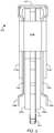
- FIG. 3 shows a view of an edge of the DIMM package 200 of FIG. 2 .
- FIG. 3 shows the printed circuit board 202, the integrated circuits 204a,b , the layers of thermal interface material 206a,b, the heat spreader plates 208a,b, and the spring clips 210a,b,c.
- Features of particular interest for the disclosed technology include the upper surface 302 of the heat spreader plates 208 formed by one or more of the side plates 208 extending across the edge of the printed circuit board 202 opposite the connector edge 304.
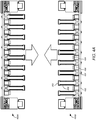
- FIG. 4A shows two identical printed circuit assemblies 400A and 400B according to one embodiment.
- Each of printed circuit assemblies 400A and 400B includes a system board 402, upon which a plurality of printed circuit board sockets, one of which is referenced as 404, are mounted in parallel.
- a cooling pipe 406 is mounted adjacent to, and parallel to each printed circuit board socket 404.
- a layer of thermal interface material 408 is disposed upon, and thermally coupled to, each cooling pipe 406 on the side of the cooling pipe opposite the system board 402.
- a plurality of DIMM packages, one of which is referenced as 200, are electrically coupled to the system board 402.
- the connector edge 304 of each DIMM package 200 is disposed in one of the printed circuit board sockets 404.
- the top surfaces 302 of the heat spreaders 208a,b on each of the printed circuit assemblies 400 contact, and become thermally coupled with, the thermal interface material layers 408 on the other printed circuit assembly 400, as indicated at 410A and 410B.
- the DIMM packages 200 on each printed circuit assembly 400 are cooled by the cooling pipes 406 of the other printed circuit assembly 400.
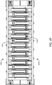
- FIG. 5 is a perspective view of a printed circuit assembly 400 with the DIMM packages 200 removed. Referring to FIG. 5 , the printed circuit board sockets 404, the adjacent and parallel cooling pipes 406, and the layers of thermal interface material 408 disposed upon the parallel cooling pipes 406 may be seen clearly.
- FIG. 6 is a perspective view of a printed circuit assembly 400 with the DIMM packages 200 installed in the printed circuit board sockets 404, and with manifolds attached.
- a first end of each cooling pipe 406 is coupled to an input manifold 606A
- a second end of each cooling pipe 406 is coupled to an output manifold 606B.
- cool liquid enters the cooling pipes through the input manifold 606A
- heated liquid leaves the cooling pipes through the output manifold 606B.
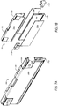
- FIGS. 7A and 7B show a DIMM package featuring an external hinge according to one embodiment.
- FIG. 7B shows an exploded view
- FIG. 7A shows an assembled view.
- the DIMM package 700 includes a printed circuit board 702 upon which are mounted one or more integrated circuits, shown generally at 704.
- the printed circuit board 702 is generally double-sided, with integrated circuits 704 mounted upon both sides.
- thermal interface material 706 is thermally coupled to the integrated circuits 704.
- One common thermal interface material is a thermal gap pad. However, other thermal interface materials may be used.
- a removable heat spreader constituting a pair of side plates 708a,b joined by an external hinge 720 is brought into physical contact with the layers of thermal interface material 706a,b, and is thereby thermally coupled to the thermal interface material 706a,b.
- the side plates 708a,b may be made of aluminum. However, other materials may be used to form the side plates 708a,b.
- One or more removable spring clips 710a,b may be positioned about the side plates 708 to press them against the thermal interface material 706 to ensure proper thermal coupling.
- FIGS. 8A and 8B show a DIMM package featuring an internal hinge according to one embodiment.
- FIG. 8B shows an exploded view
- FIG. 8A shows an assembled view.
- the DIMM package 800 includes a printed circuit board 802 upon which are mounted one or more integrated circuits, shown generally at 804.
- the printed circuit board 802 is generally double-sided, with integrated circuits 804 mounted upon both sides.
- thermal interface material 806 is thermally coupled to the integrated circuits 804.
- One common thermal interface material is a thermal gap pad. However, other thermal interface materials may be used.
- a removable heat spreader constituting a pair of side plates 808 joined by an internal hinge 820 is brought into physical contact with the layers of thermal interface material 806, and is thereby thermally coupled to the thermal interface material 806.
- the side plates 808 may be made of aluminum. However, other materials may be used to form the side plates 808.
- One or more removable spring clips 810 may be positioned about the side plates 808 to press them against the thermal interface material 806 to ensure proper thermal coupling.
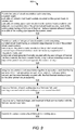
- FIG. 9 shows a process 900 according to one embodiment. Although the steps of the process are shown in a particular sequence, some or all of the steps may be performed in other sequences, in parallel, or combinations thereof. Some of the steps may be omitted.
- two printed circuit assemblies 400 are provided, at 902.
- Each printed circuit assembly 400 includes a system board 402, plurality of printed circuit board sockets 404 mounted on the system board 402 in parallel, a plurality of cooling pipes 406 each mounted on the system board 402 parallel to and adjacent to a respective one of the printed circuit board sockets 404, each of the cooling pipes 406 having a first layer of thermal interface material 408 adhered thereto on a side of the cooling pipe 406 opposite the system board 402.
- the process 900 includes providing a plurality of integrated circuit modules, at 904.
- the integrated circuit modules may include one or more DIMM packages 200.
- Each integrated circuit module includes a printed circuit board 202 having a connector edge 304 disposed in one of the printed circuit board sockets 404, one or more integrated circuits 204 mounted on the printed circuit board 202, a second layer of thermal interface material 206 thermally coupled with the integrated circuits 204, and a removable heat spreader 208 thermally coupled with the second layer of thermal interface material 206, the heat spreader 208 having a top surface 302 extending across an edge of the printed circuit board 202 opposite the connector edge 304.
- the two printed circuit assemblies are brought together in opposition, at 906, such that the top surfaces 302 of the heat spreaders 208 on each of the printed circuit assemblies 400 contact, and become thermally coupled with, the first thermal interface material layers 408 on the other printed circuit assembly 400.
- the process 900 includes coupling a first end of each cooling pipe 406 to a first manifold 606A, and coupling a second end of each cooling pipe 406 to a second manifold 606B, at 908.
- the process 900 includes coupling a pump 110, heat exchanger 112, and reservoir 114 in fluid communication with the first and second manifolds 606A,B, at 910.
- the process 900 includes operating the pump 110 to pass a liquid through the cooling pipes 406.
Landscapes
- Engineering & Computer Science (AREA)
- Microelectronics & Electronic Packaging (AREA)
- Theoretical Computer Science (AREA)
- Physics & Mathematics (AREA)
- General Engineering & Computer Science (AREA)
- Human Computer Interaction (AREA)
- General Physics & Mathematics (AREA)
- Manufacturing & Machinery (AREA)
- Computer Hardware Design (AREA)
- Thermal Sciences (AREA)
- Cooling Or The Like Of Semiconductors Or Solid State Devices (AREA)
- Cooling Or The Like Of Electrical Apparatus (AREA)
Abstract
Description
- Modern computer systems generate large quantities of heat. While some of this heat is generated by power supplies and the like, the majority of the heat is generated by integrated circuits such as processors and memory chips. In order to function properly, these computer systems must be kept within a certain temperature range. Therefore, the heat generated by these processors and memory chips must be dissipated or otherwise removed.
- The present disclosure, in accordance with one or more various embodiments, is described in detail with reference to the following figures. The figures are provided for purposes of illustration only and merely depict typical or example embodiments.
-
FIG. 1 is a context diagram of a system in which various embodiments may be implemented. -
FIGS. 2A and 2B show a DIMM package according to one embodiment. -
FIG. 3 shows a view of an edge of the DIMM package ofFIG. 2 . -
FIG. 4A shows two identical printed circuit assemblies according to one embodiment. -
FIG. 4B shows the two printed circuit assemblies ofFIG. 4A brought together in opposition such that the top surfaces of the heat spreaders on each of the printed circuit assemblies contact, and become thermally coupled with, the thermal interface material layers on the other printed circuit assembly. -
FIG. 5 is a perspective view of a printed circuit assembly with the DIMM packages removed. -
FIG. 6 is a perspective view of a printed circuit assembly with theDIMM packages 200 installed in the printed circuit board sockets, and with manifolds attached. -
FIGS. 7A and 7B show a DIMM package featuring an external hinge according to one embodiment. -
FIGS. 8A and 8B show a DIMM package featuring an internal hinge according to one embodiment. -
FIG. 9 shows a process according to one embodiment. - The figures are not exhaustive and do not limit the present disclosure to the precise form disclosed.
- Integrated circuits such as Dual Inline Memory Modules (DIMMs) generate a lot of heat, especially in high-density configurations. Many techniques exist to cool them, but there are disadvantages associated with these existing techniques. Air cooling is noisy, and therefore undesirable when deployed near office workers/in a working environment. Liquid immersion cooling is messy when maintenance of the DIMMs is required. Another approach uses DIMM packages that encapsulate the DIMMs in a heat spreader that is thermally coupled to a cooling pipe that circulates a chilled liquid.
- The disclosed embodiments pair two system boards, each having cooling pipes, interleaved between DIMM modules. When the boards are brought together in opposition, the DIMM modules on each system board are cooled by the cooling pipes on the other system board. This approach allows greater densities of DIMMs than previous approaches while still providing the necessary cooling. This approach is also quiet, and so can be located near office personnel. This approach also allows easy maintenance, without the spills associated with liquid immersion cooling systems. While various embodiments are described with reference to DIMMs, it should be appreciated that the disclosed technology can be used to cool any integrated circuit or similar system(s) and element(s)/components therein.
-
FIG. 1 is a context diagram of asystem 100 in which various embodiments may be implemented.System 100 includes acomputing component 120 that includes aprocessor 104 and amemory 106. Thememory 106 includes a number ofDIMM packages 108.System 100 also includes acooling loop 130. Thecooling loop 130 includes apump 110, aheat exchanger 112, and areservoir 114. Thepump 110 providescool liquid 130 to the DIMMpackages 108. The heat generated by theDIMM packages 108 is passed to the liquid, heating it and cooling theDIMM packages 108. Thepump 110 removes the heatedliquid 132 from theDIMM packages 108. Theheat exchanger 112 cools the heatedliquid 132. Thereservoir 114 accommodates changes in the volume of the liquid. -
FIGS. 2A and 2B show aDIMM package 200 according to one embodiment.FIG. 2A is a perspective view of the DIMMpackage 200 in its assembled state. An exploded view ofDIMM package 200 is shown inFIG. 2B . The DIMMpackage 200 includes a printedcircuit board 202 on which one or more integrated circuits, shown generally at 204, are mounted. The printedcircuit board 202 is generally double-sided, with integratedcircuits 204 mounted upon both sides. - Layers of
thermal interface material 206a,b are thermally coupled to the integratedcircuits 204. One common thermal interface material is a thermal gap pad. However, other thermal interface materials may be used, for example such as thermal grease and the like. - In the depicted embodiment, a removable heat spreader having a pair of
side plates 208a,b is brought into physical contact with the layers ofthermal interface material 206a,b, and is thereby thermally coupled to thethermal interface material 206 a,b. Theside plates 208 a,b may be made of aluminum. However, other materials may be used to form theside plates 208 a,b, for example such as stainless steel, or the like. Theside plates 208 a,b may be identical in order to reduce manufacturing costs. - One or more
removable spring clips 210a,b,c,d may be positioned about theside plates 208 a,b to press them against thethermal interface material 206 a,b to ensure proper thermal coupling. -
FIG. 3 shows a view of an edge of the DIMMpackage 200 ofFIG. 2 .FIG. 3 shows theprinted circuit board 202, the integratedcircuits 204a,b , the layers ofthermal interface material 206a,b, theheat spreader plates 208a,b, and thespring clips 210a,b,c. Features of particular interest for the disclosed technology include theupper surface 302 of the heat spreader plates 208 formed by one or more of the side plates 208 extending across the edge of the printedcircuit board 202 opposite theconnector edge 304. These features are discussed in more detail below. -
FIG. 4A shows two identical printedcircuit assemblies circuit assemblies system board 402, upon which a plurality of printed circuit board sockets, one of which is referenced as 404, are mounted in parallel. A coolingpipe 406 is mounted adjacent to, and parallel to each printedcircuit board socket 404. A layer ofthermal interface material 408 is disposed upon, and thermally coupled to, each coolingpipe 406 on the side of the cooling pipe opposite thesystem board 402. A plurality of DIMM packages, one of which is referenced as 200, are electrically coupled to thesystem board 402. In particular, theconnector edge 304 of eachDIMM package 200 is disposed in one of the printedcircuit board sockets 404. - When the two printed
circuit assemblies FIG 4B , thetop surfaces 302 of theheat spreaders 208a,b on each of the printedcircuit assemblies 400 contact, and become thermally coupled with, the thermal interface material layers 408 on the other printedcircuit assembly 400, as indicated at 410A and 410B. In this configuration, the DIMM packages 200 on each printedcircuit assembly 400 are cooled by the coolingpipes 406 of the other printedcircuit assembly 400. -
FIG. 5 is a perspective view of a printedcircuit assembly 400 with the DIMM packages 200 removed. Referring toFIG. 5 , the printedcircuit board sockets 404, the adjacent andparallel cooling pipes 406, and the layers ofthermal interface material 408 disposed upon theparallel cooling pipes 406 may be seen clearly. -
FIG. 6 is a perspective view of a printedcircuit assembly 400 with the DIMM packages 200 installed in the printedcircuit board sockets 404, and with manifolds attached. Referring back toFIG. 5 , a first end of each coolingpipe 406 is coupled to aninput manifold 606A, and a second end of each coolingpipe 406 is coupled to anoutput manifold 606B. In operation, cool liquid enters the cooling pipes through theinput manifold 606A, and heated liquid leaves the cooling pipes through theoutput manifold 606B. -
FIGS. 7A and 7B show a DIMM package featuring an external hinge according to one embodiment.FIG. 7B shows an exploded view, whileFIG. 7A shows an assembled view. TheDIMM package 700 includes a printedcircuit board 702 upon which are mounted one or more integrated circuits, shown generally at 704. The printedcircuit board 702 is generally double-sided, withintegrated circuits 704 mounted upon both sides. - Layers of thermal interface material 706 are thermally coupled to the
integrated circuits 704. One common thermal interface material is a thermal gap pad. However, other thermal interface materials may be used. - In the depicted embodiment, a removable heat spreader constituting a pair of
side plates 708a,b joined by anexternal hinge 720 is brought into physical contact with the layers ofthermal interface material 706a,b, and is thereby thermally coupled to thethermal interface material 706a,b. Theside plates 708a,b may be made of aluminum. However, other materials may be used to form theside plates 708a,b. - One or more
removable spring clips 710a,b may be positioned about the side plates 708 to press them against the thermal interface material 706 to ensure proper thermal coupling. -
FIGS. 8A and 8B show a DIMM package featuring an internal hinge according to one embodiment.FIG. 8B shows an exploded view, whileFIG. 8A shows an assembled view. TheDIMM package 800 includes a printedcircuit board 802 upon which are mounted one or more integrated circuits, shown generally at 804. The printedcircuit board 802 is generally double-sided, withintegrated circuits 804 mounted upon both sides. - Layers of thermal interface material 806 are thermally coupled to the
integrated circuits 804. One common thermal interface material is a thermal gap pad. However, other thermal interface materials may be used. - In the depicted embodiment, a removable heat spreader constituting a pair of side plates 808 joined by an
internal hinge 820 is brought into physical contact with the layers of thermal interface material 806, and is thereby thermally coupled to the thermal interface material 806. The side plates 808 may be made of aluminum. However, other materials may be used to form the side plates 808. - One or more removable spring clips 810 may be positioned about the side plates 808 to press them against the thermal interface material 806 to ensure proper thermal coupling.
-
FIG. 9 shows aprocess 900 according to one embodiment. Although the steps of the process are shown in a particular sequence, some or all of the steps may be performed in other sequences, in parallel, or combinations thereof. Some of the steps may be omitted. Referring toFIG. 9 , two printedcircuit assemblies 400 are provided, at 902. Each printedcircuit assembly 400 includes asystem board 402, plurality of printedcircuit board sockets 404 mounted on thesystem board 402 in parallel, a plurality of coolingpipes 406 each mounted on thesystem board 402 parallel to and adjacent to a respective one of the printedcircuit board sockets 404, each of the coolingpipes 406 having a first layer ofthermal interface material 408 adhered thereto on a side of thecooling pipe 406 opposite thesystem board 402. - The
process 900 includes providing a plurality of integrated circuit modules, at 904. For example, the integrated circuit modules may include one or more DIMM packages 200. Each integrated circuit module includes a printedcircuit board 202 having aconnector edge 304 disposed in one of the printedcircuit board sockets 404, one or moreintegrated circuits 204 mounted on the printedcircuit board 202, a second layer of thermal interface material 206 thermally coupled with theintegrated circuits 204, and a removable heat spreader 208 thermally coupled with the second layer of thermal interface material 206, the heat spreader 208 having atop surface 302 extending across an edge of the printedcircuit board 202 opposite theconnector edge 304. - The two printed circuit assemblies are brought together in opposition, at 906, such that the
top surfaces 302 of the heat spreaders 208 on each of the printedcircuit assemblies 400 contact, and become thermally coupled with, the first thermal interface material layers 408 on the other printedcircuit assembly 400. - The
process 900 includes coupling a first end of each coolingpipe 406 to afirst manifold 606A, and coupling a second end of each coolingpipe 406 to asecond manifold 606B, at 908. - The
process 900 includes coupling apump 110,heat exchanger 112, andreservoir 114 in fluid communication with the first andsecond manifolds 606A,B, at 910. - The
process 900 includes operating thepump 110 to pass a liquid through the coolingpipes 406. - As used herein, the term "or" may be construed in either an inclusive or exclusive sense. Moreover, the description of resources, operations, or structures in the singular shall not be read to exclude the plural. Conditional language, such as, among others, "can," "could," "might," or "may," unless specifically stated otherwise, or otherwise understood within the context as used, is generally intended to convey that certain embodiments include, while other embodiments do not include, certain features, elements and/or steps.
- Terms and phrases used in this document, and variations thereof, unless otherwise expressly stated, should be construed as open ended as opposed to limiting. Adjectives such as "conventional," "traditional," "normal," "standard," "known," and terms of similar meaning should not be construed as limiting the item described to a given time period or to an item available as of a given time, but instead should be read to encompass conventional, traditional, normal, or standard technologies that may be available or known now or at any time in the future. The presence of broadening words and phrases such as "one or more," "at least," "but not limited to" or other like phrases in some instances shall not be read to mean that the narrower case is intended or required in instances where such broadening phrases may be absent.
- Further embodiments are set out in the following clauses:
- 1. A liquid-cooled integrated circuit system comprising:
- two printed circuit assemblies each comprising
- a system board,
- a plurality of printed circuit board sockets mounted on the system board in parallel, and
- a plurality of cooling pipes each mounted on the system board parallel to and adjacent to a respective one of the printed circuit board sockets, each of the cooling pipes having a first layer of thermal interface material adhered thereto on a side of the cooling pipe opposite the system board; and
- a plurality of integrated circuit modules each comprising
- a printed circuit board having a connector edge disposed in one of the printed circuit board sockets,
- one or more integrated circuits mounted on the printed circuit board,
- a second layer of thermal interface material thermally coupled with the integrated circuits, and
- a removable heat spreader thermally coupled with the second layer of thermal interface material, the heat spreader having a top surface extending across an edge of the printed circuit board opposite the connector edge;
- wherein the two printed circuit assemblies are placed together in opposition such that the top surfaces of the heat spreaders on each of the printed circuit assemblies contact, and become thermally coupled with, the first thermal interface material layers on the other printed circuit assembly.
- two printed circuit assemblies each comprising
- 2. The liquid-cooled integrated circuit system of clause 1, further comprising:
- a first manifold coupled to a first end of each cooling pipe; and
- a second manifold coupled to a second end of each cooling pipe.
- 3. The liquid-cooled integrated circuit system of clause 1, further comprising:
a removable spring clip positioned about the heat spreader, wherein the removable spring clip presses the heat spreader against the second layer of thermal interface material when positioned about the heat spreader. - 4. The liquid-cooled integrated circuit system of clause 1, wherein the heat spreader comprises:
- two side plates thermally coupled with the second layer of thermal interface material;
- wherein at least one of the side plates defines the top surface of the heat spreader.
- 5. The liquid-cooled integrated circuit system of clause 4, wherein the heat spreader further comprises:
an external hinge pivotably joining the two side plates. - 6. The liquid-cooled integrated circuit system of clause 4, wherein the heat spreader further comprises:
an internal hinge pivotably joining the two side plates. - 7. An apparatus comprising:
- two printed circuit assemblies, each comprising:
- a system board,
- a plurality of printed circuit board sockets on the system board,
- a plurality of liquid cooling pipes each coupled to the system board adjacent to one of the memory module sockets,
- a plurality of integrated circuit modules connected to the printed circuit board sockets, and
- a plurality of heat spreaders, each thermally coupled with one of the integrated circuit modules;
- wherein the printed circuit assemblies are arranged opposite one another such that the integrated circuit modules of the two printed circuit assemblies are interleaved with one another and top surfaces of the heat spreaders of each of the printed circuit assemblies are thermally coupled with the liquid cooling pipes of the other printed circuit assembly.
- two printed circuit assemblies, each comprising:
- 8. The apparatus of clause 7, further comprising:
- a first manifold coupled to a first end of each liquid cooling pipe; and
- a second manifold coupled to a second end of each liquid cooling pipe.
- 9. The apparatus of clause 8, further comprising:
a cooling loop comprising- a pump in fluid communication with the first and second manifolds,
- a heat exchanger in fluid communication with the first and second manifolds, and
- a reservoir in fluid communication with the first and second manifolds.
- 10. The apparatus of clause 7, further comprising:
a removable spring clip positioned about each heat spreader. - 11. The apparatus of clause 7, wherein each heat spreader comprises:
two side plates, wherein at least one of the side plates defines the top surface of the heat spreader. - 12. The apparatus of clause 11, wherein the heat spreader further comprises:
an external hinge pivotably joining the two side plates. - 13. The apparatus of clause 11, wherein the heat spreader further comprises:
an internal hinge pivotably joining the two side plates. - 14. A method comprising:
- providing two printed circuit assemblies, each comprising:
- a system board,
- a plurality of printed circuit board sockets on the system board,
- a plurality of liquid cooling pipes each coupled to the system board adjacent to one of the memory module sockets,
- a plurality of integrated circuit modules connected to the printed circuit board sockets, and
- a plurality of heat spreaders, each thermally coupled with one of the integrated circuit modules; and
- arranging the printed circuit assemblies opposite one another such that the integrated circuit modules of the two printed circuit assemblies are interleaved with one another and top surfaces of the heat spreaders of each of the printed circuit assemblies are thermally coupled with the liquid cooling pipes of the other printed circuit assembly.
- providing two printed circuit assemblies, each comprising:
- 15. The method of clause 14, further comprising:
passing a liquid through the liquid cooling pipes. - 16. The method of clause 15, further comprising:
- coupling a first end of each liquid cooling pipe to a first manifold;
- coupling a second end of each liquid cooling pipe to a second manifold; and
- passing the liquid through the manifolds and the liquid cooling pipes.
- 17. The method of clause 14, further comprising:
for each of the integrated circuit modules, placing a removable spring clip about the heat spreader. - 18. The method of clause 14, wherein the heat spreader comprises:
two side plates, wherein at least one of the side plates defines the top surface of the heat spreader. - 19. The method of clause 19, wherein the heat spreader further comprises:
an external hinge pivotably joining the two side plates. - 20. The method of clause 19, wherein the heat spreader further comprises:
an internal hinge pivotably joining the two side plates.
Claims (15)
- An apparatus comprising:two printed circuit assemblies, each comprising:a system board,a plurality of printed circuit board sockets on the system board,a plurality of liquid cooling pipes each coupled to the system board adjacent to one of the printed circuit board sockets,a plurality of integrated circuit modules connected to the printed circuit board sockets, anda plurality of heat spreaders, each thermally coupled with one of the integrated circuit modules;wherein the printed circuit assemblies are arranged opposite one another such that the integrated circuit modules of the two printed circuit assemblies are interleaved with one another and top surfaces of the heat spreaders of each of the printed circuit assemblies are thermally coupled with the liquid cooling pipes of the other printed circuit assembly.
- The apparatus of claim 1, further comprising:a first manifold coupled to a first end of each liquid cooling pipe; anda second manifold coupled to a second end of each liquid cooling pipe.
- The apparatus of claim 1 or 2, further comprising:
a cooling loop comprisinga pump in fluid communication with the first and second manifolds,a heat exchanger in fluid communication with the first and second manifolds, anda reservoir in fluid communication with the first and second manifolds. - The apparatus of any preceding claim , further comprising:
a removable spring clip positioned about each heat spreader. - The apparatus of any preceding claim , wherein each heat spreader comprises:
two side plates, wherein at least one of the side plates defines the top surface of the heat spreader. - The apparatus of claim 5, wherein the heat spreader further comprises:
an external hinge pivotably joining the two side plates. - The apparatus of claim 5, wherein the heat spreader further comprises:
an internal hinge pivotably joining the two side plates. - A liquid-cooled integrated circuit system comprising the apparatus of any preceding claim, wherein:the plurality of printed circuit board sockets are mounted on the system board in parallel;the plurality of cooling pipes are each mounted on the system board parallel to a respective one of the printed circuit board sockets, each of the cooling pipes having a first layer of thermal interface material adhered thereto on a side of the cooling pipe opposite the system board;the plurality of integrated circuit modules each comprises:a printed circuit board having a connector edge disposed in one of the printed circuit board sockets,one or more integrated circuits mounted on the printed circuit board,a second layer of thermal interface material thermally coupled with the integrated circuits, andthe heat spreaders are removable heat spreaders thermally coupled with the second layer of thermal interface material, the heat spreader having a top surface extending across an edge of the printed circuit board opposite the connector edge;wherein the two printed circuit assemblies are placed together in opposition such that the top surfaces of the heat spreaders on each of the printed circuit assemblies contact, and become thermally coupled with, the first thermal interface material layers on the other printed circuit assembly.
- A method comprising:providing two printed circuit assemblies, each comprising:a system board,a plurality of printed circuit board sockets on the system board,a plurality of liquid cooling pipes each coupled to the system board adjacent to one of the printed circuit board sockets,a plurality of integrated circuit modules connected to the printed circuit board sockets, anda plurality of heat spreaders, each thermally coupled with one of the integrated circuit modules; andarranging the printed circuit assemblies opposite one another such that the integrated circuit modules of the two printed circuit assemblies are interleaved with one another and top surfaces of the heat spreaders of each of the printed circuit assemblies are thermally coupled with the liquid cooling pipes of the other printed circuit assembly.
- The method of claim 9, further comprising:
passing a liquid through the liquid cooling pipes. - The method of claim 10, further comprising:coupling a first end of each liquid cooling pipe to a first manifold;coupling a second end of each liquid cooling pipe to a second manifold; andpassing the liquid through the manifolds and the liquid cooling pipes.
- The method of any of claims 9 to 11, further comprising:
for each of the integrated circuit modules, placing a removable spring clip about the heat spreader. - The method of any of claims 9 to 12, wherein the heat spreader comprises:
two side plates, wherein at least one of the side plates defines the top surface of the heat spreader. - The method of claim 13, wherein the heat spreader further comprises:
an external hinge pivotably joining the two side plates. - The method of claim 13, wherein the heat spreader further comprises:
an internal hinge pivotably joining the two side plates.
Applications Claiming Priority (1)
| Application Number | Priority Date | Filing Date | Title |
|---|---|---|---|
| US16/165,960 US10499488B1 (en) | 2018-10-19 | 2018-10-19 | Liquid-cooled integrated circuit system |
Publications (2)
| Publication Number | Publication Date |
|---|---|
| EP3647902A1 true EP3647902A1 (en) | 2020-05-06 |
| EP3647902B1 EP3647902B1 (en) | 2021-12-01 |
Family
ID=68165479
Family Applications (1)
| Application Number | Title | Priority Date | Filing Date |
|---|---|---|---|
| EP19201558.4A Active EP3647902B1 (en) | 2018-10-19 | 2019-10-04 | Liquid-cooled integrated circuit system |
Country Status (3)
| Country | Link |
|---|---|
| US (1) | US10499488B1 (en) |
| EP (1) | EP3647902B1 (en) |
| CN (1) | CN111083903B (en) |
Families Citing this family (11)
| Publication number | Priority date | Publication date | Assignee | Title |
|---|---|---|---|---|
| US10750639B2 (en) * | 2018-11-20 | 2020-08-18 | Hewlett Packard Enterprise Development Lp | Cooling memory modules |
| JP2020202283A (en) * | 2019-06-10 | 2020-12-17 | 富士通株式会社 | Liquid cooling jackets, liquid cooling systems and electronics |
| CN113748750A (en) * | 2019-08-23 | 2021-12-03 | 慧与发展有限责任合伙企业 | Conformal heat transport device for dual in-line memory module cooling applications |
| CN115513728B (en) * | 2020-01-15 | 2025-05-30 | 莫列斯有限公司 | Connector components |
| CN113823932B (en) * | 2020-06-18 | 2025-07-18 | 莫列斯有限公司 | Connector components |
| US11737237B2 (en) * | 2021-02-03 | 2023-08-22 | Baidu Usa Llc | Liquid cooling design for peripheral electronics |
| CN115902308A (en) | 2021-08-13 | 2023-04-04 | 史密斯互连美洲公司 | Test socket assembly with liquid cooling frame for semiconductor integrated circuits |
| US12543567B2 (en) * | 2021-11-12 | 2026-02-03 | Intel Corporation | Tunable stack-up DIMM form factor cold plate with embedded peltier devices for enhanced cooling capability |
| US12309971B2 (en) * | 2022-01-20 | 2025-05-20 | Super Micro Computer, Inc. | Dual-stacked motherboards for fluid immersion cooling |
| US12317438B2 (en) * | 2022-07-08 | 2025-05-27 | Quanta Computer Inc. | Dust-proof mechanism for memory module |
| US12701682B2 (en) | 2024-04-18 | 2026-08-04 | Caterpillar Inc. | Cooling system for power electronics units |
Citations (3)
| Publication number | Priority date | Publication date | Assignee | Title |
|---|---|---|---|---|
| US20090237883A1 (en) * | 2008-03-24 | 2009-09-24 | Fujitsu Limited | Board unit and electronic apparatus |
| US20120279047A1 (en) * | 2011-05-06 | 2012-11-08 | International Business Machines Corporation | Method of fabricating a cooled electronic system |
| US20130135812A1 (en) * | 2011-11-28 | 2013-05-30 | International Business Machines Corporation | Liquid-cooling memory modules with liquid flow pipes between memory module sockets |
Family Cites Families (8)
| Publication number | Priority date | Publication date | Assignee | Title |
|---|---|---|---|---|
| US20080123297A1 (en) | 2006-05-15 | 2008-05-29 | Isothermal Systems Research, Inc. | Hybrid clamshell blade system |
| CN102414813B (en) * | 2009-04-29 | 2014-04-09 | 惠普开发有限公司 | Printed circuit board cooling assembly |
| US9245820B2 (en) * | 2010-03-08 | 2016-01-26 | International Business Machines Corporation | Liquid DIMM cooling device |
| US8638559B2 (en) * | 2011-11-10 | 2014-01-28 | International Business Machines Corporation | User-serviceable liquid DIMM cooling system |
| US8659897B2 (en) | 2012-01-27 | 2014-02-25 | International Business Machines Corporation | Liquid-cooled memory system having one cooling pipe per pair of DIMMs |
| US9158348B2 (en) * | 2012-06-29 | 2015-10-13 | Asetek Danmark A/S | Server memory cooling apparatus |
| US9577227B2 (en) | 2013-10-17 | 2017-02-21 | Tesla Motors, Inc. | Cell module assemblies |
| US9761919B2 (en) | 2014-02-25 | 2017-09-12 | Tesla, Inc. | Energy storage system with heat pipe thermal management |
-
2018
- 2018-10-19 US US16/165,960 patent/US10499488B1/en active Active
-
2019
- 2019-10-04 EP EP19201558.4A patent/EP3647902B1/en active Active
- 2019-10-18 CN CN201910991438.3A patent/CN111083903B/en active Active
Patent Citations (3)
| Publication number | Priority date | Publication date | Assignee | Title |
|---|---|---|---|---|
| US20090237883A1 (en) * | 2008-03-24 | 2009-09-24 | Fujitsu Limited | Board unit and electronic apparatus |
| US20120279047A1 (en) * | 2011-05-06 | 2012-11-08 | International Business Machines Corporation | Method of fabricating a cooled electronic system |
| US20130135812A1 (en) * | 2011-11-28 | 2013-05-30 | International Business Machines Corporation | Liquid-cooling memory modules with liquid flow pipes between memory module sockets |
Also Published As
| Publication number | Publication date |
|---|---|
| EP3647902B1 (en) | 2021-12-01 |
| CN111083903A (en) | 2020-04-28 |
| CN111083903B (en) | 2021-11-12 |
| US10499488B1 (en) | 2019-12-03 |
Similar Documents
| Publication | Publication Date | Title |
|---|---|---|
| US10499488B1 (en) | Liquid-cooled integrated circuit system | |
| US12274024B2 (en) | Cooling device for cooling components of a circuit board | |
| US10705578B2 (en) | Heat removal from memory modules | |
| US9298231B2 (en) | Methods of fabricating a coolant-cooled electronic assembly | |
| US8432691B2 (en) | Liquid cooling system for an electronic system | |
| US9456527B2 (en) | Fabricating separable and integrated heat sinks facilitating cooling multi-component electronic assembly | |
| US8358505B2 (en) | Integrated liquid cooling system | |
| US8749968B1 (en) | Liquid cooling system for a server | |
| US9265178B2 (en) | Thermal transfer and coolant-cooled structures facilitating cooling of electronics card(s) | |
| US9379039B2 (en) | Heat transfer for electronic equipment | |
| US11612050B2 (en) | Heat dissipation device | |
| US20130058038A1 (en) | Thermal interposer liquid cooling system | |
| US20200163253A1 (en) | Cooling memory modules | |
| US5001601A (en) | Modular cooling fixture for power transistors | |
| CN112823573B (en) | Thermal Interface Device for PCI Express M.2 Printed Circuit Assemblies | |
| WO2012057763A1 (en) | Integrated liquid cooling system | |
| JP3782912B2 (en) | Cooling device and cooling method for processor and companion voltage regulator | |
| EP2633378A1 (en) | Liquid cooling system for an electronic system | |
| JPH05121612A (en) | Conductive cooling structure | |
| JPS58155799A (en) | Electronic device |
Legal Events
| Date | Code | Title | Description |
|---|---|---|---|
| PUAI | Public reference made under article 153(3) epc to a published international application that has entered the european phase |
Free format text: ORIGINAL CODE: 0009012 |
|
| STAA | Information on the status of an ep patent application or granted ep patent |
Free format text: STATUS: THE APPLICATION HAS BEEN PUBLISHED |
|
| AK | Designated contracting states |
Kind code of ref document: A1 Designated state(s): AL AT BE BG CH CY CZ DE DK EE ES FI FR GB GR HR HU IE IS IT LI LT LU LV MC MK MT NL NO PL PT RO RS SE SI SK SM TR |
|
| AX | Request for extension of the european patent |
Extension state: BA ME |
|
| STAA | Information on the status of an ep patent application or granted ep patent |
Free format text: STATUS: REQUEST FOR EXAMINATION WAS MADE |
|
| 17P | Request for examination filed |
Effective date: 20200727 |
|
| RBV | Designated contracting states (corrected) |
Designated state(s): AL AT BE BG CH CY CZ DE DK EE ES FI FR GB GR HR HU IE IS IT LI LT LU LV MC MK MT NL NO PL PT RO RS SE SI SK SM TR |
|
| STAA | Information on the status of an ep patent application or granted ep patent |
Free format text: STATUS: EXAMINATION IS IN PROGRESS |
|
| 17Q | First examination report despatched |
Effective date: 20210324 |
|
| GRAP | Despatch of communication of intention to grant a patent |
Free format text: ORIGINAL CODE: EPIDOSNIGR1 |
|
| STAA | Information on the status of an ep patent application or granted ep patent |
Free format text: STATUS: GRANT OF PATENT IS INTENDED |
|
| RIC1 | Information provided on ipc code assigned before grant |
Ipc: G06F 1/20 20060101AFI20210519BHEP Ipc: H05K 1/02 20060101ALI20210519BHEP Ipc: H01L 23/40 20060101ALI20210519BHEP Ipc: H01L 23/473 20060101ALI20210519BHEP |
|
| INTG | Intention to grant announced |
Effective date: 20210622 |
|
| GRAS | Grant fee paid |
Free format text: ORIGINAL CODE: EPIDOSNIGR3 |
|
| GRAA | (expected) grant |
Free format text: ORIGINAL CODE: 0009210 |
|
| STAA | Information on the status of an ep patent application or granted ep patent |
Free format text: STATUS: THE PATENT HAS BEEN GRANTED |
|
| AK | Designated contracting states |
Kind code of ref document: B1 Designated state(s): AL AT BE BG CH CY CZ DE DK EE ES FI FR GB GR HR HU IE IS IT LI LT LU LV MC MK MT NL NO PL PT RO RS SE SI SK SM TR |
|
| REG | Reference to a national code |
Ref country code: GB Ref legal event code: FG4D |
|
| REG | Reference to a national code |
Ref country code: AT Ref legal event code: REF Ref document number: 1452385 Country of ref document: AT Kind code of ref document: T Effective date: 20211215 Ref country code: CH Ref legal event code: EP |
|
| REG | Reference to a national code |
Ref country code: IE Ref legal event code: FG4D |
|
| REG | Reference to a national code |
Ref country code: DE Ref legal event code: R096 Ref document number: 602019009687 Country of ref document: DE |
|
| REG | Reference to a national code |
Ref country code: LT Ref legal event code: MG9D |
|
| REG | Reference to a national code |
Ref country code: NL Ref legal event code: MP Effective date: 20211201 |
|
| REG | Reference to a national code |
Ref country code: AT Ref legal event code: MK05 Ref document number: 1452385 Country of ref document: AT Kind code of ref document: T Effective date: 20211201 |
|
| PG25 | Lapsed in a contracting state [announced via postgrant information from national office to epo] |
Ref country code: RS Free format text: LAPSE BECAUSE OF FAILURE TO SUBMIT A TRANSLATION OF THE DESCRIPTION OR TO PAY THE FEE WITHIN THE PRESCRIBED TIME-LIMIT Effective date: 20211201 Ref country code: LT Free format text: LAPSE BECAUSE OF FAILURE TO SUBMIT A TRANSLATION OF THE DESCRIPTION OR TO PAY THE FEE WITHIN THE PRESCRIBED TIME-LIMIT Effective date: 20211201 Ref country code: FI Free format text: LAPSE BECAUSE OF FAILURE TO SUBMIT A TRANSLATION OF THE DESCRIPTION OR TO PAY THE FEE WITHIN THE PRESCRIBED TIME-LIMIT Effective date: 20211201 Ref country code: BG Free format text: LAPSE BECAUSE OF FAILURE TO SUBMIT A TRANSLATION OF THE DESCRIPTION OR TO PAY THE FEE WITHIN THE PRESCRIBED TIME-LIMIT Effective date: 20220301 Ref country code: AT Free format text: LAPSE BECAUSE OF FAILURE TO SUBMIT A TRANSLATION OF THE DESCRIPTION OR TO PAY THE FEE WITHIN THE PRESCRIBED TIME-LIMIT Effective date: 20211201 |
|
| PG25 | Lapsed in a contracting state [announced via postgrant information from national office to epo] |
Ref country code: SE Free format text: LAPSE BECAUSE OF FAILURE TO SUBMIT A TRANSLATION OF THE DESCRIPTION OR TO PAY THE FEE WITHIN THE PRESCRIBED TIME-LIMIT Effective date: 20211201 Ref country code: PL Free format text: LAPSE BECAUSE OF FAILURE TO SUBMIT A TRANSLATION OF THE DESCRIPTION OR TO PAY THE FEE WITHIN THE PRESCRIBED TIME-LIMIT Effective date: 20211201 Ref country code: NO Free format text: LAPSE BECAUSE OF FAILURE TO SUBMIT A TRANSLATION OF THE DESCRIPTION OR TO PAY THE FEE WITHIN THE PRESCRIBED TIME-LIMIT Effective date: 20220301 Ref country code: LV Free format text: LAPSE BECAUSE OF FAILURE TO SUBMIT A TRANSLATION OF THE DESCRIPTION OR TO PAY THE FEE WITHIN THE PRESCRIBED TIME-LIMIT Effective date: 20211201 Ref country code: HR Free format text: LAPSE BECAUSE OF FAILURE TO SUBMIT A TRANSLATION OF THE DESCRIPTION OR TO PAY THE FEE WITHIN THE PRESCRIBED TIME-LIMIT Effective date: 20211201 Ref country code: GR Free format text: LAPSE BECAUSE OF FAILURE TO SUBMIT A TRANSLATION OF THE DESCRIPTION OR TO PAY THE FEE WITHIN THE PRESCRIBED TIME-LIMIT Effective date: 20220302 Ref country code: ES Free format text: LAPSE BECAUSE OF FAILURE TO SUBMIT A TRANSLATION OF THE DESCRIPTION OR TO PAY THE FEE WITHIN THE PRESCRIBED TIME-LIMIT Effective date: 20211201 |
|
| PG25 | Lapsed in a contracting state [announced via postgrant information from national office to epo] |
Ref country code: NL Free format text: LAPSE BECAUSE OF FAILURE TO SUBMIT A TRANSLATION OF THE DESCRIPTION OR TO PAY THE FEE WITHIN THE PRESCRIBED TIME-LIMIT Effective date: 20211201 |
|
| PG25 | Lapsed in a contracting state [announced via postgrant information from national office to epo] |
Ref country code: SM Free format text: LAPSE BECAUSE OF FAILURE TO SUBMIT A TRANSLATION OF THE DESCRIPTION OR TO PAY THE FEE WITHIN THE PRESCRIBED TIME-LIMIT Effective date: 20211201 Ref country code: SK Free format text: LAPSE BECAUSE OF FAILURE TO SUBMIT A TRANSLATION OF THE DESCRIPTION OR TO PAY THE FEE WITHIN THE PRESCRIBED TIME-LIMIT Effective date: 20211201 Ref country code: RO Free format text: LAPSE BECAUSE OF FAILURE TO SUBMIT A TRANSLATION OF THE DESCRIPTION OR TO PAY THE FEE WITHIN THE PRESCRIBED TIME-LIMIT Effective date: 20211201 Ref country code: PT Free format text: LAPSE BECAUSE OF FAILURE TO SUBMIT A TRANSLATION OF THE DESCRIPTION OR TO PAY THE FEE WITHIN THE PRESCRIBED TIME-LIMIT Effective date: 20220401 Ref country code: EE Free format text: LAPSE BECAUSE OF FAILURE TO SUBMIT A TRANSLATION OF THE DESCRIPTION OR TO PAY THE FEE WITHIN THE PRESCRIBED TIME-LIMIT Effective date: 20211201 Ref country code: CZ Free format text: LAPSE BECAUSE OF FAILURE TO SUBMIT A TRANSLATION OF THE DESCRIPTION OR TO PAY THE FEE WITHIN THE PRESCRIBED TIME-LIMIT Effective date: 20211201 |
|
| REG | Reference to a national code |
Ref country code: DE Ref legal event code: R097 Ref document number: 602019009687 Country of ref document: DE |
|
| PG25 | Lapsed in a contracting state [announced via postgrant information from national office to epo] |
Ref country code: IS Free format text: LAPSE BECAUSE OF FAILURE TO SUBMIT A TRANSLATION OF THE DESCRIPTION OR TO PAY THE FEE WITHIN THE PRESCRIBED TIME-LIMIT Effective date: 20220401 |
|
| PLBE | No opposition filed within time limit |
Free format text: ORIGINAL CODE: 0009261 |
|
| STAA | Information on the status of an ep patent application or granted ep patent |
Free format text: STATUS: NO OPPOSITION FILED WITHIN TIME LIMIT |
|
| PG25 | Lapsed in a contracting state [announced via postgrant information from national office to epo] |
Ref country code: DK Free format text: LAPSE BECAUSE OF FAILURE TO SUBMIT A TRANSLATION OF THE DESCRIPTION OR TO PAY THE FEE WITHIN THE PRESCRIBED TIME-LIMIT Effective date: 20211201 Ref country code: AL Free format text: LAPSE BECAUSE OF FAILURE TO SUBMIT A TRANSLATION OF THE DESCRIPTION OR TO PAY THE FEE WITHIN THE PRESCRIBED TIME-LIMIT Effective date: 20211201 |
|
| 26N | No opposition filed |
Effective date: 20220902 |
|
| REG | Reference to a national code |
Ref country code: DE Ref legal event code: R081 Ref document number: 602019009687 Country of ref document: DE Owner name: HEWLETT PACKARD ENTERPRISE DEVELOPMENT LP, SPR, US Free format text: FORMER OWNER: HEWLETT PACKARD ENTERPRISE DEVELOPMENT LP, HOUSTON, TX, US Ref country code: DE Ref legal event code: R082 Ref document number: 602019009687 Country of ref document: DE Representative=s name: MARKS & CLERK (LUXEMBOURG) LLP, LU |
|
| PG25 | Lapsed in a contracting state [announced via postgrant information from national office to epo] |
Ref country code: SI Free format text: LAPSE BECAUSE OF FAILURE TO SUBMIT A TRANSLATION OF THE DESCRIPTION OR TO PAY THE FEE WITHIN THE PRESCRIBED TIME-LIMIT Effective date: 20211201 |
|
| PG25 | Lapsed in a contracting state [announced via postgrant information from national office to epo] |
Ref country code: MC Free format text: LAPSE BECAUSE OF FAILURE TO SUBMIT A TRANSLATION OF THE DESCRIPTION OR TO PAY THE FEE WITHIN THE PRESCRIBED TIME-LIMIT Effective date: 20211201 Ref country code: IT Free format text: LAPSE BECAUSE OF FAILURE TO SUBMIT A TRANSLATION OF THE DESCRIPTION OR TO PAY THE FEE WITHIN THE PRESCRIBED TIME-LIMIT Effective date: 20211201 |
|
| REG | Reference to a national code |
Ref country code: CH Ref legal event code: PL |
|
| REG | Reference to a national code |
Ref country code: BE Ref legal event code: MM Effective date: 20221031 |
|
| PG25 | Lapsed in a contracting state [announced via postgrant information from national office to epo] |
Ref country code: LU Free format text: LAPSE BECAUSE OF NON-PAYMENT OF DUE FEES Effective date: 20221004 |
|
| PG25 | Lapsed in a contracting state [announced via postgrant information from national office to epo] |
Ref country code: LI Free format text: LAPSE BECAUSE OF NON-PAYMENT OF DUE FEES Effective date: 20221031 Ref country code: FR Free format text: LAPSE BECAUSE OF NON-PAYMENT OF DUE FEES Effective date: 20221031 Ref country code: CH Free format text: LAPSE BECAUSE OF NON-PAYMENT OF DUE FEES Effective date: 20221031 |
|
| PG25 | Lapsed in a contracting state [announced via postgrant information from national office to epo] |
Ref country code: BE Free format text: LAPSE BECAUSE OF NON-PAYMENT OF DUE FEES Effective date: 20221031 |
|
| PG25 | Lapsed in a contracting state [announced via postgrant information from national office to epo] |
Ref country code: IE Free format text: LAPSE BECAUSE OF NON-PAYMENT OF DUE FEES Effective date: 20221004 |
|
| PG25 | Lapsed in a contracting state [announced via postgrant information from national office to epo] |
Ref country code: HU Free format text: LAPSE BECAUSE OF FAILURE TO SUBMIT A TRANSLATION OF THE DESCRIPTION OR TO PAY THE FEE WITHIN THE PRESCRIBED TIME-LIMIT; INVALID AB INITIO Effective date: 20191004 |
|
| PG25 | Lapsed in a contracting state [announced via postgrant information from national office to epo] |
Ref country code: CY Free format text: LAPSE BECAUSE OF FAILURE TO SUBMIT A TRANSLATION OF THE DESCRIPTION OR TO PAY THE FEE WITHIN THE PRESCRIBED TIME-LIMIT Effective date: 20211201 |
|
| PG25 | Lapsed in a contracting state [announced via postgrant information from national office to epo] |
Ref country code: MK Free format text: LAPSE BECAUSE OF FAILURE TO SUBMIT A TRANSLATION OF THE DESCRIPTION OR TO PAY THE FEE WITHIN THE PRESCRIBED TIME-LIMIT Effective date: 20211201 |
|
| PG25 | Lapsed in a contracting state [announced via postgrant information from national office to epo] |
Ref country code: MT Free format text: LAPSE BECAUSE OF FAILURE TO SUBMIT A TRANSLATION OF THE DESCRIPTION OR TO PAY THE FEE WITHIN THE PRESCRIBED TIME-LIMIT Effective date: 20211201 |
|
| PG25 | Lapsed in a contracting state [announced via postgrant information from national office to epo] |
Ref country code: TR Free format text: LAPSE BECAUSE OF FAILURE TO SUBMIT A TRANSLATION OF THE DESCRIPTION OR TO PAY THE FEE WITHIN THE PRESCRIBED TIME-LIMIT Effective date: 20211201 |
|
| PGFP | Annual fee paid to national office [announced via postgrant information from national office to epo] |
Ref country code: DE Payment date: 20251028 Year of fee payment: 7 |
|
| PGFP | Annual fee paid to national office [announced via postgrant information from national office to epo] |
Ref country code: GB Payment date: 20251023 Year of fee payment: 7 |