EP3647895A1 - Leader movable body, follower movable body, and group travel control system - Google Patents
Leader movable body, follower movable body, and group travel control system Download PDFInfo
- Publication number
- EP3647895A1 EP3647895A1 EP19204924.5A EP19204924A EP3647895A1 EP 3647895 A1 EP3647895 A1 EP 3647895A1 EP 19204924 A EP19204924 A EP 19204924A EP 3647895 A1 EP3647895 A1 EP 3647895A1
- Authority
- EP
- European Patent Office
- Prior art keywords
- movable body
- freedom
- degree
- leader
- vehicle
- Prior art date
- Legal status (The legal status is an assumption and is not a legal conclusion. Google has not performed a legal analysis and makes no representation as to the accuracy of the status listed.)
- Granted
Links
Images





Classifications
-
- G—PHYSICS
- G05—CONTROLLING; REGULATING
- G05D—SYSTEMS FOR CONTROLLING OR REGULATING NON-ELECTRIC VARIABLES
- G05D1/00—Control of position, course, altitude or attitude of land, water, air or space vehicles, e.g. using automatic pilots
- G05D1/02—Control of position or course in two dimensions
- G05D1/021—Control of position or course in two dimensions specially adapted to land vehicles
- G05D1/0287—Control of position or course in two dimensions specially adapted to land vehicles involving a plurality of land vehicles, e.g. fleet or convoy travelling
- G05D1/0291—Fleet control
- G05D1/0295—Fleet control by at least one leading vehicle of the fleet
-
- B—PERFORMING OPERATIONS; TRANSPORTING
- B62—LAND VEHICLES FOR TRAVELLING OTHERWISE THAN ON RAILS
- B62K—CYCLES; CYCLE FRAMES; CYCLE STEERING DEVICES; RIDER-OPERATED TERMINAL CONTROLS SPECIALLY ADAPTED FOR CYCLES; CYCLE AXLE SUSPENSIONS; CYCLE SIDECARS, FORECARS, OR THE LIKE
- B62K5/00—Cycles with handlebars, equipped with three or more main road wheels
- B62K5/003—Cycles with four or more wheels, specially adapted for disabled riders, e.g. personal mobility type vehicles with four wheels
- B62K5/007—Cycles with four or more wheels, specially adapted for disabled riders, e.g. personal mobility type vehicles with four wheels power-driven
-
- B—PERFORMING OPERATIONS; TRANSPORTING
- B60—VEHICLES IN GENERAL
- B60W—CONJOINT CONTROL OF VEHICLE SUB-UNITS OF DIFFERENT TYPE OR DIFFERENT FUNCTION; CONTROL SYSTEMS SPECIALLY ADAPTED FOR HYBRID VEHICLES; ROAD VEHICLE DRIVE CONTROL SYSTEMS FOR PURPOSES NOT RELATED TO THE CONTROL OF A PARTICULAR SUB-UNIT
- B60W30/00—Purposes of road vehicle drive control systems not related to the control of a particular sub-unit, e.g. of systems using conjoint control of vehicle sub-units
- B60W30/14—Adaptive cruise control
- B60W30/16—Control of distance between vehicles, e.g. keeping a distance to preceding vehicle
- B60W30/165—Automatically following the path of a preceding lead vehicle, e.g. "electronic tow-bar"
-
- B—PERFORMING OPERATIONS; TRANSPORTING
- B62—LAND VEHICLES FOR TRAVELLING OTHERWISE THAN ON RAILS
- B62K—CYCLES; CYCLE FRAMES; CYCLE STEERING DEVICES; RIDER-OPERATED TERMINAL CONTROLS SPECIALLY ADAPTED FOR CYCLES; CYCLE AXLE SUSPENSIONS; CYCLE SIDECARS, FORECARS, OR THE LIKE
- B62K11/00—Motorcycles, engine-assisted cycles or motor scooters with one or two wheels
-
- B—PERFORMING OPERATIONS; TRANSPORTING
- B62—LAND VEHICLES FOR TRAVELLING OTHERWISE THAN ON RAILS
- B62K—CYCLES; CYCLE FRAMES; CYCLE STEERING DEVICES; RIDER-OPERATED TERMINAL CONTROLS SPECIALLY ADAPTED FOR CYCLES; CYCLE AXLE SUSPENSIONS; CYCLE SIDECARS, FORECARS, OR THE LIKE
- B62K11/00—Motorcycles, engine-assisted cycles or motor scooters with one or two wheels
- B62K11/007—Automatic balancing machines with single main ground engaging wheel or coaxial wheels supporting a rider
-
- G—PHYSICS
- G05—CONTROLLING; REGULATING
- G05D—SYSTEMS FOR CONTROLLING OR REGULATING NON-ELECTRIC VARIABLES
- G05D1/00—Control of position, course, altitude or attitude of land, water, air or space vehicles, e.g. using automatic pilots
- G05D1/02—Control of position or course in two dimensions
- G05D1/021—Control of position or course in two dimensions specially adapted to land vehicles
- G05D1/0287—Control of position or course in two dimensions specially adapted to land vehicles involving a plurality of land vehicles, e.g. fleet or convoy travelling
- G05D1/0291—Fleet control
-
- G—PHYSICS
- G08—SIGNALLING
- G08G—TRAFFIC CONTROL SYSTEMS
- G08G1/00—Traffic control systems for road vehicles
- G08G1/22—Platooning, i.e. convoy of communicating vehicles
-
- H—ELECTRICITY
- H04—ELECTRIC COMMUNICATION TECHNIQUE
- H04W—WIRELESS COMMUNICATION NETWORKS
- H04W4/00—Services specially adapted for wireless communication networks; Facilities therefor
- H04W4/30—Services specially adapted for particular environments, situations or purposes
- H04W4/40—Services specially adapted for particular environments, situations or purposes for vehicles, e.g. vehicle-to-pedestrians [V2P]
- H04W4/46—Services specially adapted for particular environments, situations or purposes for vehicles, e.g. vehicle-to-pedestrians [V2P] for vehicle-to-vehicle communication [V2V]
Definitions
- the present invention relates to a leader movable body, a follower movable body, and a group travel control system.
- Japanese Patent Application Publication No. 2016-78719 discloses, as an example of the ultra-compact movable body, an inverted mobile object that accommodates a user in a standing position and allows the user to operate the mobile object. The user can control a travel direction of the inverted mobile object by performing operations such as operating a handle, moving a centroid position, and changing the inclination of a step.
- the present invention provides a technique of setting a leader-follower relationship between movable bodies, and allowing a leader movable body to set the degree of freedom relevant to movement of a follower movable body.
- a first aspect of the present invention is a leader movable body.
- the leader movable body includes a degree of freedom setting unit and a transmitter.
- the degree of freedom setting unit is configured to set a degree of freedom relevant to movement of a follower movable body.
- the transmitter is configured to transmit the degree of freedom to the follower movable body.
- the follower movable body is configured to perform group travel with respect to the leader movable body.
- the degree of freedom may include an allowable value of at least one parameter, out of a movement distance, a movement speed, a movement acceleration, and a movement range of the follower movable body.
- the leader movable body may include an input unit configured to allow a user to input an instruction for setting the degree of freedom relevant to movement of the follower movable body.
- the degree of freedom setting unit may be configured to set the degree of freedom in accordance with the instruction for setting the degree of freedom to be input.
- the leader movable body may include a sensor unit configured to detect a surrounding environment of the leader movable body.
- the degree of freedom setting unit may be configured to set the degree of freedom based on a detection result of the sensor unit.
- the leader movable body may include a generation unit configured to generate a forcing command for forcibly controlling movement of the follower movable body, irrespective of the degree of freedom set for the follower movable body.
- the degree of freedom may be used on controlling movement of the follower movable body.
- the follower movable body may be configured to be controlled such that movement of the follower movable body is controlled in accordance with the degree of freedom.
- a second aspect of the present invention is a follower movable body.
- the follower movable body includes a receiver and a movement control unit.
- the receiver is configured to receive a degree of freedom relevant to movement from a leader movable body.
- the movement control unit is configured to control movement of the follower movable body in accordance with the degree of freedom.
- the follower movable body is configured to perform group travel with respect to the leader movable body.
- the follower movable body may include a notification unit configured to notify the degree of freedom.
- a third aspect of the present invention is a group travel control system.
- the group travel control system includes a leader movable body, and a follower movable body.
- the follower movable body is configured to perform group travel with respect to the leader movable body.
- the leader movable body includes a degree of freedom setting unit configured to set a degree of freedom relevant to movement of the follower movable body, and a transmitter configured to transmit the degree of freedom to the follower movable body.
- the follower movable body includes a receiver configured to receive the degree of freedom from the leader movable body, and a movement control unit configured to control movement of the follower movable body in accordance with the degree of freedom.
- the group travel control system may be configured such that a leader-follower relationship is set between the leader movable body and the follower movable body.
- the first aspect, the second aspect, and the third aspect of the present invention it becomes possible to set the leader-follower relationship between movable bodies, and to allow the leader movable body to set the degree of freedom relevant to movement of the follower movable body.
- FIG. 1 is a concept view of a group travel control system 1000 according to the present embodiment.
- FIG. 1 shows the case where one vehicle serves as a leader vehicle Vp (hereinafter, parent vehicle), and other vehicles travel as follower vehicles Vw (hereinafter, worker vehicles).
- the number of the parent vehicles Vp and the worker vehicles Vw may be any number, such as one or more.
- the present embodiment assumes the vehicles as so-called ultra-compact movable bodies (e.g., ultra-compact electric vehicles, that is, inverted mobile objects in FIG. 1 ) for one person. However, it is not intended to limit the vehicles to the ultra-compact movable bodies.
- Examples of the case assumed by the system 1000 include the case where a parent or parents operate the parent vehicles Vp, and a child or children operate the worker vehicles Vw, and the case where, for example, a tour guide operates the parent vehicle Vp and tour participants operate the worker vehicles.
- the system 1000 may be used in any cases.
- a leader-follower relationship can be set between the parent vehicle Vp and the worker vehicle Vw.
- the parent vehicle Vp can set the degree of freedom relevant to movement of the worker vehicle Vw (that is, the movement can be limited) (the details will be described later).
- the worker vehicle Vw can freely move within the range of the set degree of freedom relevant to the movement (hereinafter, simply referred to as "degree of freedom"), while following the parent vehicle Vp.
- degree of freedom refers to a travel of the parent vehicle Vp and the worker vehicles Vw, with a leader-follower relationship being set therebetween and the degree of freedom being set for the worker vehicle Vw.
- FIG. 2 is an appearance view of the parent vehicle Vp and the worker vehicle Vw.
- the vehicles VP and Vw are each called a vehicle V.
- the vehicle V is a coaxial two wheeler that can move while maintaining an inverted state by individually controlling a pair of wheels 140.
- the vehicle V includes a vehicle body 110, a pair of right and left step units 120 on which a user rides on, the step units 120 being attached to the vehicle body 110.
- the vehicle V also includes an operating handle 130 for the user to grip, the operating handle 130 being tiltable and attached to the vehicle body 110, a pair of right and left wheels 140 rotatably attached to the vehicle body 110, and a driving unit 150 that drives the wheels 140.
- the vehicle V can move backward and forward by the user shifting the center of gravity back and forth so as to incline the step units 120 of the vehicle body 110 back and forth.
- the vehicle V can turn right and left by the user shifting the center of gravity right and left so as to incline the step units 120 of the vehicle body 110 right and left.
- FIG. 3 is a block diagram showing the system configuration of the parent vehicle (leader movable body) Vp.
- the vehicle body 110 incorporates the driving unit 150 that includes an electric motor and various gears. Under the control of a controller 210, the driving unit 150 performs inversion control so as to prevent a fall, while enabling the vehicle V to travel.
- the vehicle body 110 incorporates a power source unit 160 that is configured of a lithium ion battery or the like.
- the power source unit 160 supplies electric power to devices that constitute the vehicle V, and other electronic devices.
- a communication unit 170 is provided to establish a wireless car-to-car communication with the worker vehicles Vw.
- the communication unit 170 is configured to include a transmitter, a receiver, and a communication interface in conformity with telecommunications standards for wireless LAN, cellular phones, or the like. It is not intended to limit the wireless communication between the parent vehicle Vp and the worker vehicles Vw to a direct car-to-car communication. Rather, the wireless communication may be an indirect car-to-car communication with another vehicle that functions as a relay station, a road-to-vehicle communication with a fixed station that functions as a relay station, and also a terrestrial-satellite communication with a satellite station that functions as a relay station.
- the user who rides in the parent vehicle Vp is called “parent user”
- the user who rides in the worker vehicle Vw is called “worker user”.
- the user who rides in a vehicle that is not particularly limited is simply called "user.”
- the input unit 180 is provided in the vicinity of the operating handle 130.
- the input unit 180 is configured of an operation button, an operation switch, a touch panel, a sound collector for allowing voice input, and the like.
- Properly operating the input unit 180 enables a parent user to input an instruction for setting the degree of freedom of the worker vehicle Vw, and an instruction for generating a forcing command (described later) for the worker vehicle Vw.
- the parent user properly operates the input unit 180 to set a leader-follower relationship where the vehicle V to be operated by the parent user is defined as a parent vehicle Vp and the vehicles V to be operated by worker users as worker vehicles Vw.
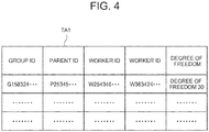
- FIG. 4 illustrates a registration content of the group management database DB1.
- a group management table TA1 that associates a group ID for identifying a group having the leader-follower relationship established, a parent ID for identifying a parent vehicle Vp, worker IDs for identifying worker vehicles Vw, and set degree of freedom of the worker vehicles Vw.
- the ID that identifies the own vehicle is registered as a parent ID.
- the ID that identifies the own vehicle is registered as a worker ID.
- the vehicle body 110 incorporates a sensor unit 190 that is configured of various measuring instruments including an attitude sensor 191, a rotation sensor 192, an inter-vehicle distance sensor 193, and a GPS sensor 194.
- the attitude sensor 191 is provided in the vehicle body 110 to detect and output attitude information regarding the vehicle body 110, the operating handle 130, or the like.
- the attitude sensor 191 is configured to detect attitude information when the vehicle V travels.
- the attitude sensor 191 is configured of a gyro sensor, an acceleration sensor, or the like.
- the attitude sensor 191 detects attitude information (what is called a three-dimensional attitude angle, or the like) corresponding to the inclination.
- the attitude sensor 191 outputs the detected attitude information to the controller 210.
- the rotation sensor 192 is provided in each of the wheels 140.
- the rotation sensor 192 detects rotation information such as a rotation angle, a rotation angular speed, and a rotation angle acceleration of each of the wheels 140.
- Each of the rotation sensors 192 is configured of, for example, a rotary encoder, a resolver, or the like.
- Each of the rotation sensors 192 outputs the detected rotation information to the controller 210.
- the inter-vehicle distance sensor 193 is provided in the vehicle body 110 to detect inter-vehicle distance information indicating an inter-vehicle distance between the own vehicle and other vehicles.
- the inter-vehicle distance sensor 193 detects inter-vehicle distance information by using a radar device, such as a laser radar and a millimeter-wave radar, and outputs the detected inter-vehicle distance information to the controller 210.
- the GPS sensor 194 is a component member of a location information measurement system using satellites.
- the GPS sensor 194 measures the location (longitude, latitude, altitude, or the like) of the own vehicle by receiving electric waves from a large number of GPS Satellites, and outputs the measured location as location information to the controller 210.
- a notification unit 200 is configured of a speaker that outputs sound, a light that turns on and blinks an alarm lamp, and a display that displays a warning, or the like.
- the notification unit 200 notifies the user about various information based on a notification signal from the controller 210.
- the notification unit 200 may be used to notify the set degree of freedom.
- the degree of freedom set at the present time may be displayed on the display as a character message, or the degree of freedom set at the present time may be output from the speaker as a voice message.
- a controller 210 is configured of a processor such as a central processing unit (CPU), and a primary storage including a read only memory (ROM), and a random access memory (RAM) to centrically control the parent vehicle Vp.
- the controller 210 includes a drive control unit 211, a degree of freedom setting unit 212, and a forcing command generation unit 213.
- the controller 210 may have the configuration of an auxiliary storage, such as a hard disk drive and a removable media.
- the auxiliary storage may store an operating system (OS), various programs, and various tables.
- OS operating system
- the programs stored in the auxiliary storage may be loaded to a work area of the primary storage and be executed there. Through execution of the programs, each component unit of the controller 210 may be controlled such that a function matched with a prescribed target may be implemented.
- the drive control unit 211 generates and outputs a control signal for controlling the driving unit 150, based on detection values output from various sensors mounted on the vehicle V.
- the drive control unit 211 executes a prescribed arithmetic process, based on the attitude information output from the attitude sensor 191, the rotation information regarding the wheels 140 output from the rotation sensors 192, or the like.
- the drive control unit 211 generates a control signal necessary for the vehicle to move at a prescribed speed while maintaining an inverted state.
- the drive control unit 211 then outputs the generated control signal to the driving unit 150.
- the degree of freedom setting unit 212 Based on the instruction for setting the degree of freedom input from the input unit 180, the degree of freedom setting unit 212 sets the degree of freedom relevant to movement of the worker vehicle Vw, and registers the set degree of freedom in the group management database DB1. The degree of freedom setting unit 212 transmits the set degree of freedom to the worker vehicle Vw. Once the degree of freedom of the worker vehicle Vw is set, the degree of freedom setting unit 212 monitors whether the worker vehicle Vw follows the set degree of freedom (that is, whether the worker vehicle Vw moves in the range of the degree of freedom).
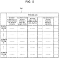
- FIG. 5 illustrates the registration content of a degree of freedom management table TA2 held by the degree of freedom setting unit 212.
- Registered in the degree of freedom management table TA2 are allowable values of parameters relevant to movement for each degree of freedom that can be set.
- the degree of freedom can be set as numerical values in the range of, for example, "0" to "100.”
- a degree of freedom "0” represents a severest restriction, where the free movement of the worker vehicle Vw is not permitted in principle (what is called a complete follower).
- a degree of freedom "100” represents no restriction, where the worker vehicle Vw can freely move in principle.
- the parameters relevant to restricted movement include a movement distance, a movement speed, a movement acceleration, and a movement range.
- a movement range Am may be set in a substantially circular shape as shown by A of FIG. 6 .
- the movement range Am may be set in a substantially fan shape, or the movement range Am may be set in a substantially windmill shape as shown by C of FIG. 6 .
- the forcing command generation unit 213 generates a forcing command for forcibly controlling the movement of the worker vehicle Vw, irrespective of the degree of freedom ("0" to "100") set for the worker vehicle Vw.
- Examples of the forcing command may include an emergency shutdown command that is generated in order to prevent a collision with other vehicles. However, it is not intended to limit the forcing command to the emergency shutdown command.
- the forcing command generation unit 213 When the parent user inputs an instruction for emergency shutdown (for example, a voice input of "simultaneous stop” or the like), the forcing command generation unit 213 generates a forcing command in accordance with the input instruction, and transmits the forcing command to the worker vehicle Vw that is in a leader-follower relationship.
- the forcing command may be transmitted to all the worker vehicles Vw in the leader-follower relationship in principle. It is also possible to transmit the forcing command only to a specific worker vehicle Vw in the leader-follower relationship.
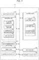
- FIG. 7 is a block diagram showing the system configuration of the worker vehicle (follower movable body) Vw.
- the configurational aspects of the worker vehicle Vw are mostly in common with those of the parent vehicle Vp. Accordingly, corresponding component members are designated by corresponding reference numerals to omit detailed description.
- the controller 210 of the worker vehicle Vw includes a movement control unit 214 instead of the degree of freedom setting unit 212 and the forcing command generation unit 213 shown in FIG. 3 .
- the movement control unit 214 controls the movement of the worker vehicle Vw in accordance with the degree of freedom received from the parent vehicle Vp.
- the degree of freedom management table TA2 shown in previously shown FIG. 5 is registered in the movement control unit 214.
- the movement control unit 214 controls the movement of the worker vehicle Vw such that the parameters such as the movement distance, the movement speed, the movement acceleration, and the movement range become less than the allowable values set for the degree of freedom "60.”
- the movement control unit 214 executes the received forcing command at top priority, irrespective of the degree of freedom set for the vehicle Vw. For example, when receiving the forcing command for emergency shutdown, the movement control unit 214 performs emergency shutdown of the worker vehicle Vw by operating a brake mechanism (illustration omitted) or the like.
- the degree of freedom received from the parent vehicle Vp may be notified by using the notification unit 200 such that the degree of freedom set for the worker vehicle Vw can be confirmed.
- the degree of freedom set at the present time may be displayed on the display as a character message, or the degree of freedom set at the present time may be output from the speaker as a voice message.
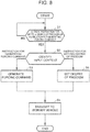
- FIG. 8 is a flowchart showing an operation process of the parent vehicle Vp.
- the controller 210 of the parent vehicle Vp determines whether or not an instruction for setting the degree of freedom or an instruction for generating a forcing command is input through the input unit 180 (step S1). When determining that neither of the instructions is input (step S1; NO), the controller 210 repeatedly executes the process of step S1. When detecting that the instruction for setting the degree of freedom or the instruction for generating a forcing command is input while repeatedly executing the process of step S1 (step S1; YES), the controller 210 identifies an input content as one of the instruction for setting the degree of freedom and the instruction for generating a forcing command (step S2).
- step S3 the controller 210 generates a forcing command for forcibly controlling the movement of the worker vehicle Vw (for example, a forcing command for emergency shutdown), and transmits the generated command to the worker vehicle Vw (step S4). Then, the controller 210 ends the process.
- a forcing command for forcibly controlling the movement of the worker vehicle Vw for example, a forcing command for emergency shutdown
- step S5 the controller 210 sets the degree of freedom (for example, degree of freedom "60") relevant to the movement of the worker vehicle Vw, and registers the set degree of freedom in the group management database DB1.
- the controller 210 then transmits the set degree of freedom to the worker vehicle Vw (step S4), and ends the process.
- FIG. 9 is a flowchart illustrating an operation process of the worker vehicle Vw.
- the controller 210 of the worker vehicle Vw determines whether or not the degree of freedom or the forcing command is received from the parent vehicle Vp through the communication unit 170 (step SA1). When determining that neither of the instructions is received (step SA1; NO), the controller 210 repeatedly executes the process of step SA1. When receiving the degree of freedom or a forcing command while repeatedly executing the process of step SA1 (step SA1; YES), the controller 210 identifies a reception content as one of the degree of freedom and a forcing command (step SA2).
- step SA3 the controller 210 performs operation in accordance with the forcing command (for example, emergency shutdown of the worker vehicle Vw), and ends the process.
- the forcing command for example, emergency shutdown of the worker vehicle Vw
- step SA4 when determining that the reception content is the degree of freedom, the controller 210 shifts to step SA4, where the movement of the worker vehicle Vw is restricted. For example, when the reception content is an instruction to change the degree of freedom from "60" to "30", the controller 210 controls the movement of the worker vehicle Vw such that the parameters become less than the allowable values set for the changed degree of freedom "30.” Then, the controller 210 ends the process.
- the present embodiment enables the parent vehicle Vp that sets the leader-follower relationship with the worker vehicles Vw to set the degree of freedom relevant to the movement of the worker vehicle Vw.
- the worker vehicle Vw with a set degree of freedom can freely move in the range of the set degree of freedom, while following the parent vehicle Vp, instead of being forced to completely follow the parent vehicle Vp. Accordingly, the user who controls the worker vehicle Vw can actively determine a moving route in the range of the degree of freedom, and therefore the user can enjoy the pleasure of moving with the worker vehicle Vw.
- the degree of freedom of the worker vehicle Vw is manually set and changed in accordance with an input operation by the parent user.
- the degree of freedom of the worker vehicle Vw may automatically be set and changed in accordance with the detection result of the sensor unit 190.
- the degree of freedom setting unit 212 of the parent vehicle Vp changes the set degree of freedom from a high value to a low value (for example, "50" to "25”) to impose a more strict movement restriction on the worker vehicle Vw.
- a high value for example, "50” to "25”
- a low value for example, "50" to "25”
- FIG. 10 is an appearance view of a vehicle V according to a modification.
- the vehicle V includes a vehicle body 310, and a seat unit 320 where a user can seat, the seat unit 320 being attached to the vehicle body 310.
- the vehicle V also includes an operating unit 330 that enables the user to grip and drive the vehicle, and four driving wheels 340 rotatably attached to the vehicle body 310.
- the vehicle V according to the modification is a compact vehicle for up to two people, the vehicle V allowing a user himself or herself to operate.
- the vehicle V applied to the present modification is not limited to the ultra-compact movable body. Rather, the vehicle V may include vehicles other than the ultra-compact movable body, such as an ordinary motor vehicle.
- the vehicle V may have any number of wheels.
- application targets of the present invention are not intended to be limited to vehicles such as motorcycles and automobiles.
- the present invention may also be applicable to various types of movable bodies (such as boats and flying bodies) without wheels.
- the present invention is not limited to the embodiment disclosed, but may be performed in other various forms without departing from the scope of the present invention. Therefore, the embodiment disclosed is in all respects illustrative and is not considered as the basis for restrictive interpretation. For example, the order of the process steps described above may optionally be changed or executed in parallel, without producing inconsistency in the contents of the process.
- units do not simply refer to physical component members. Rather, they also refer to the cases where the processes executed by "units” are implemented by software. Moreover, the process to be executed by one "unit” may be implemented by two or more physical component members or devices, and the process to be executed by two or more "units” may be implemented by one physical means or device.
Landscapes
- Engineering & Computer Science (AREA)
- Physics & Mathematics (AREA)
- General Physics & Mathematics (AREA)
- Automation & Control Theory (AREA)
- Mechanical Engineering (AREA)
- Aviation & Aerospace Engineering (AREA)
- Radar, Positioning & Navigation (AREA)
- Remote Sensing (AREA)
- Transportation (AREA)
- Computer Networks & Wireless Communication (AREA)
- Signal Processing (AREA)
- Motorcycle And Bicycle Frame (AREA)
Abstract
Description
- The present invention relates to a leader movable body, a follower movable body, and a group travel control system.
- Various types of vehicles (what is called ultra-compact movable bodies) have been proposed which are smaller than automobiles and easy to maneuver, the vehicles providing user-friendly mobility for up to two people. For example, Japanese Patent Application Publication No.
2016-78719 - Since such an ultra-compact movable body provides new mobility to a wide generation, the introduction of the ultra-compact movable body is positively promoted in such places as tourist resorts. Some of the tourist resorts are providing a trial rental service of the ultra-compact movable bodies to family tourists and group tourists, as means for mobility in sight-seeing tours or archaeological tours. However, in the case where, for example, a parent and a child ride on different ultra-compact movable bodies, the child is given freedom of movement. As a result, the parent needs to pay attention to prevent undesirable situations, such as the child getting lost or going to dangerous places without asking the parent, and this makes it difficult for the parent to sufficiently enjoy sightseeing.
- The present invention provides a technique of setting a leader-follower relationship between movable bodies, and allowing a leader movable body to set the degree of freedom relevant to movement of a follower movable body.
- A first aspect of the present invention is a leader movable body. The leader movable body includes a degree of freedom setting unit and a transmitter. The degree of freedom setting unit is configured to set a degree of freedom relevant to movement of a follower movable body. The transmitter is configured to transmit the degree of freedom to the follower movable body. The follower movable body is configured to perform group travel with respect to the leader movable body.
- In the first aspect, the degree of freedom may include an allowable value of at least one parameter, out of a movement distance, a movement speed, a movement acceleration, and a movement range of the follower movable body.
- In the first aspect, the leader movable body may include an input unit configured to allow a user to input an instruction for setting the degree of freedom relevant to movement of the follower movable body. The degree of freedom setting unit may be configured to set the degree of freedom in accordance with the instruction for setting the degree of freedom to be input.
- In the first aspect, the leader movable body may include a sensor unit configured to detect a surrounding environment of the leader movable body. The degree of freedom setting unit may be configured to set the degree of freedom based on a detection result of the sensor unit.
- In the first aspect, the leader movable body may include a generation unit configured to generate a forcing command for forcibly controlling movement of the follower movable body, irrespective of the degree of freedom set for the follower movable body.
- In the first aspect, the degree of freedom may be used on controlling movement of the follower movable body.
- In the first aspect, the follower movable body may be configured to be controlled such that movement of the follower movable body is controlled in accordance with the degree of freedom.
- A second aspect of the present invention is a follower movable body. The follower movable body includes a receiver and a movement control unit. The receiver is configured to receive a degree of freedom relevant to movement from a leader movable body. The movement control unit is configured to control movement of the follower movable body in accordance with the degree of freedom. The follower movable body is configured to perform group travel with respect to the leader movable body.
- In the second aspect, the follower movable body may include a notification unit configured to notify the degree of freedom.
- A third aspect of the present invention is a group travel control system. The group travel control system includes a leader movable body, and a follower movable body. The follower movable body is configured to perform group travel with respect to the leader movable body. The leader movable body includes a degree of freedom setting unit configured to set a degree of freedom relevant to movement of the follower movable body, and a transmitter configured to transmit the degree of freedom to the follower movable body. The follower movable body includes a receiver configured to receive the degree of freedom from the leader movable body, and a movement control unit configured to control movement of the follower movable body in accordance with the degree of freedom.
- In the third aspect, the group travel control system may be configured such that a leader-follower relationship is set between the leader movable body and the follower movable body.
- According to the first aspect, the second aspect, and the third aspect of the present invention, it becomes possible to set the leader-follower relationship between movable bodies, and to allow the leader movable body to set the degree of freedom relevant to movement of the follower movable body.
- Features, advantages, and technical and industrial significance of exemplary embodiments of the invention will be described below with reference to the accompanying drawings, in which like numerals denote like elements, and wherein:
-
FIG. 1 is a concept view of a group travel control system according to the present embodiment; -
FIG. 2 is an appearance view of a parent vehicle and a worker vehicle; -
FIG. 3 is a block diagram showing the system configuration of the parent vehicle; -
FIG. 4 illustrates a registration content of a group management database; -
FIG. 5 illustrates a registration content of a degree of freedom management table; -
FIG. 6 illustrates a movement range of the worker vehicle; -
FIG. 7 is a block diagram showing the system configuration of the worker vehicle; -
FIG. 8 is a flowchart showing an operation process of the parent vehicle; -
FIG. 9 is a flowchart illustrating an operation process of the worker vehicle; and -
FIG. 10 is an appearance view of a vehicle according to a modification. - Hereinafter, preferable embodiments of the present invention will be described with reference to the accompanying drawings. In the drawings, identical or like component members are designated by identical numerals.
-
FIG. 1 is a concept view of a grouptravel control system 1000 according to the present embodiment.FIG. 1 shows the case where one vehicle serves as a leader vehicle Vp (hereinafter, parent vehicle), and other vehicles travel as follower vehicles Vw (hereinafter, worker vehicles). The number of the parent vehicles Vp and the worker vehicles Vw, may be any number, such as one or more. The present embodiment assumes the vehicles as so-called ultra-compact movable bodies (e.g., ultra-compact electric vehicles, that is, inverted mobile objects inFIG. 1 ) for one person. However, it is not intended to limit the vehicles to the ultra-compact movable bodies. Examples of the case assumed by thesystem 1000 include the case where a parent or parents operate the parent vehicles Vp, and a child or children operate the worker vehicles Vw, and the case where, for example, a tour guide operates the parent vehicle Vp and tour participants operate the worker vehicles. However, thesystem 1000 may be used in any cases. - In the group
travel control system 1000, a leader-follower relationship can be set between the parent vehicle Vp and the worker vehicle Vw. The parent vehicle Vp can set the degree of freedom relevant to movement of the worker vehicle Vw (that is, the movement can be limited) (the details will be described later). Instead of completely following the parent vehicle Vp, the worker vehicle Vw can freely move within the range of the set degree of freedom relevant to the movement (hereinafter, simply referred to as "degree of freedom"), while following the parent vehicle Vp. In the following description, "group travel" refers to a travel of the parent vehicle Vp and the worker vehicles Vw, with a leader-follower relationship being set therebetween and the degree of freedom being set for the worker vehicle Vw. -
FIG. 2 is an appearance view of the parent vehicle Vp and the worker vehicle Vw. When it is not particularly necessary to distinguish between the parent vehicle Vp and the worker vehicle Vw, the vehicles VP and Vw are each called a vehicle V. The vehicle V is a coaxial two wheeler that can move while maintaining an inverted state by individually controlling a pair ofwheels 140. The vehicle V includes avehicle body 110, a pair of right and leftstep units 120 on which a user rides on, thestep units 120 being attached to thevehicle body 110. The vehicle V also includes anoperating handle 130 for the user to grip, the operating handle 130 being tiltable and attached to thevehicle body 110, a pair of right and leftwheels 140 rotatably attached to thevehicle body 110, and adriving unit 150 that drives thewheels 140. - The vehicle V can move backward and forward by the user shifting the center of gravity back and forth so as to incline the
step units 120 of thevehicle body 110 back and forth. The vehicle V can turn right and left by the user shifting the center of gravity right and left so as to incline thestep units 120 of thevehicle body 110 right and left. -
FIG. 3 is a block diagram showing the system configuration of the parent vehicle (leader movable body) Vp. Thevehicle body 110 incorporates the drivingunit 150 that includes an electric motor and various gears. Under the control of acontroller 210, the drivingunit 150 performs inversion control so as to prevent a fall, while enabling the vehicle V to travel. - The
vehicle body 110 incorporates apower source unit 160 that is configured of a lithium ion battery or the like. Thepower source unit 160 supplies electric power to devices that constitute the vehicle V, and other electronic devices. - A
communication unit 170 is provided to establish a wireless car-to-car communication with the worker vehicles Vw. Thecommunication unit 170 is configured to include a transmitter, a receiver, and a communication interface in conformity with telecommunications standards for wireless LAN, cellular phones, or the like. It is not intended to limit the wireless communication between the parent vehicle Vp and the worker vehicles Vw to a direct car-to-car communication. Rather, the wireless communication may be an indirect car-to-car communication with another vehicle that functions as a relay station, a road-to-vehicle communication with a fixed station that functions as a relay station, and also a terrestrial-satellite communication with a satellite station that functions as a relay station. In the following description, for convenience, the user who rides in the parent vehicle Vp is called "parent user", and the user who rides in the worker vehicle Vw is called "worker user". The user who rides in a vehicle that is not particularly limited is simply called "user." - The
input unit 180 is provided in the vicinity of theoperating handle 130. Theinput unit 180 is configured of an operation button, an operation switch, a touch panel, a sound collector for allowing voice input, and the like. Properly operating theinput unit 180 enables a parent user to input an instruction for setting the degree of freedom of the worker vehicle Vw, and an instruction for generating a forcing command (described later) for the worker vehicle Vw. Before using thesystem 1000, the parent user properly operates theinput unit 180 to set a leader-follower relationship where the vehicle V to be operated by the parent user is defined as a parent vehicle Vp and the vehicles V to be operated by worker users as worker vehicles Vw. When such setting is performed, information required for setting the leader-follower relationship is exchanged between the parent vehicle Vp and the worker vehicles Vw. The information indicating the content of the leader-follower relationship, or the like, is stored in a group management database DB1 in each of the vehicles V. -
FIG. 4 illustrates a registration content of the group management database DB1. As shown inFIG. 4 , registered in the group management database DB1 is a group management table TA1 that associates a group ID for identifying a group having the leader-follower relationship established, a parent ID for identifying a parent vehicle Vp, worker IDs for identifying worker vehicles Vw, and set degree of freedom of the worker vehicles Vw. When an own vehicle is set as a parent vehicle Vp, the ID that identifies the own vehicle is registered as a parent ID. When the own vehicle is set as a worker vehicle Vw, the ID that identifies the own vehicle is registered as a worker ID. - The
vehicle body 110 incorporates asensor unit 190 that is configured of various measuring instruments including anattitude sensor 191, arotation sensor 192, aninter-vehicle distance sensor 193, and aGPS sensor 194. Theattitude sensor 191 is provided in thevehicle body 110 to detect and output attitude information regarding thevehicle body 110, theoperating handle 130, or the like. Theattitude sensor 191 is configured to detect attitude information when the vehicle V travels. For example, theattitude sensor 191 is configured of a gyro sensor, an acceleration sensor, or the like. When a user inclines the operating handle 130 forward or backward, thestep units 120 incline in the same direction. Theattitude sensor 191 detects attitude information (what is called a three-dimensional attitude angle, or the like) corresponding to the inclination. Theattitude sensor 191 outputs the detected attitude information to thecontroller 210. - The
rotation sensor 192 is provided in each of thewheels 140. Therotation sensor 192 detects rotation information such as a rotation angle, a rotation angular speed, and a rotation angle acceleration of each of thewheels 140. Each of therotation sensors 192 is configured of, for example, a rotary encoder, a resolver, or the like. Each of therotation sensors 192 outputs the detected rotation information to thecontroller 210. - The
inter-vehicle distance sensor 193 is provided in thevehicle body 110 to detect inter-vehicle distance information indicating an inter-vehicle distance between the own vehicle and other vehicles. Theinter-vehicle distance sensor 193 detects inter-vehicle distance information by using a radar device, such as a laser radar and a millimeter-wave radar, and outputs the detected inter-vehicle distance information to thecontroller 210. - For example, the
GPS sensor 194 is a component member of a location information measurement system using satellites. TheGPS sensor 194 measures the location (longitude, latitude, altitude, or the like) of the own vehicle by receiving electric waves from a large number of GPS Satellites, and outputs the measured location as location information to thecontroller 210. - A
notification unit 200 is configured of a speaker that outputs sound, a light that turns on and blinks an alarm lamp, and a display that displays a warning, or the like. Thenotification unit 200 notifies the user about various information based on a notification signal from thecontroller 210. For example, thenotification unit 200 may be used to notify the set degree of freedom. For example, the degree of freedom set at the present time may be displayed on the display as a character message, or the degree of freedom set at the present time may be output from the speaker as a voice message. - A
controller 210 is configured of a processor such as a central processing unit (CPU), and a primary storage including a read only memory (ROM), and a random access memory (RAM) to centrically control the parent vehicle Vp. Thecontroller 210 includes adrive control unit 211, a degree offreedom setting unit 212, and a forcingcommand generation unit 213. Thecontroller 210 may have the configuration of an auxiliary storage, such as a hard disk drive and a removable media. The auxiliary storage may store an operating system (OS), various programs, and various tables. The programs stored in the auxiliary storage may be loaded to a work area of the primary storage and be executed there. Through execution of the programs, each component unit of thecontroller 210 may be controlled such that a function matched with a prescribed target may be implemented. - The
drive control unit 211 generates and outputs a control signal for controlling thedriving unit 150, based on detection values output from various sensors mounted on the vehicle V. In one example, thedrive control unit 211 executes a prescribed arithmetic process, based on the attitude information output from theattitude sensor 191, the rotation information regarding thewheels 140 output from therotation sensors 192, or the like. As a result, thedrive control unit 211 generates a control signal necessary for the vehicle to move at a prescribed speed while maintaining an inverted state. Thedrive control unit 211 then outputs the generated control signal to thedriving unit 150. - Based on the instruction for setting the degree of freedom input from the
input unit 180, the degree offreedom setting unit 212 sets the degree of freedom relevant to movement of the worker vehicle Vw, and registers the set degree of freedom in the group management database DB1. The degree offreedom setting unit 212 transmits the set degree of freedom to the worker vehicle Vw. Once the degree of freedom of the worker vehicle Vw is set, the degree offreedom setting unit 212 monitors whether the worker vehicle Vw follows the set degree of freedom (that is, whether the worker vehicle Vw moves in the range of the degree of freedom). -
FIG. 5 illustrates the registration content of a degree of freedom management table TA2 held by the degree offreedom setting unit 212. Registered in the degree of freedom management table TA2 are allowable values of parameters relevant to movement for each degree of freedom that can be set. The degree of freedom can be set as numerical values in the range of, for example, "0" to "100." A degree of freedom "0" represents a severest restriction, where the free movement of the worker vehicle Vw is not permitted in principle (what is called a complete follower). A degree of freedom "100" represents no restriction, where the worker vehicle Vw can freely move in principle. InFIG. 5 , the parameters relevant to restricted movement include a movement distance, a movement speed, a movement acceleration, and a movement range. However, the parameters to be used and allowable values to be set for the parameters may optionally be set and changed depending on system design or the like. For example, as for the movement range, a movement range Am may be set in a substantially circular shape as shown by A ofFIG. 6 . In addition, as shown by B ofFIG. 6 , the movement range Am may be set in a substantially fan shape, or the movement range Am may be set in a substantially windmill shape as shown by C ofFIG. 6 . - The forcing
command generation unit 213 generates a forcing command for forcibly controlling the movement of the worker vehicle Vw, irrespective of the degree of freedom ("0" to "100") set for the worker vehicle Vw. Examples of the forcing command may include an emergency shutdown command that is generated in order to prevent a collision with other vehicles. However, it is not intended to limit the forcing command to the emergency shutdown command. When the parent user inputs an instruction for emergency shutdown (for example, a voice input of "simultaneous stop" or the like), the forcingcommand generation unit 213 generates a forcing command in accordance with the input instruction, and transmits the forcing command to the worker vehicle Vw that is in a leader-follower relationship. The forcing command may be transmitted to all the worker vehicles Vw in the leader-follower relationship in principle. It is also possible to transmit the forcing command only to a specific worker vehicle Vw in the leader-follower relationship. -
FIG. 7 is a block diagram showing the system configuration of the worker vehicle (follower movable body) Vw. As is clear from comparison with the parent vehicle Vp shown inFIG. 3 , the configurational aspects of the worker vehicle Vw are mostly in common with those of the parent vehicle Vp. Accordingly, corresponding component members are designated by corresponding reference numerals to omit detailed description. - The
controller 210 of the worker vehicle Vw includes amovement control unit 214 instead of the degree offreedom setting unit 212 and the forcingcommand generation unit 213 shown inFIG. 3 . Themovement control unit 214 controls the movement of the worker vehicle Vw in accordance with the degree of freedom received from the parent vehicle Vp. The degree of freedom management table TA2 shown in previously shownFIG. 5 is registered in themovement control unit 214. In the case where, for example, the degree of freedom is set to "60", themovement control unit 214 controls the movement of the worker vehicle Vw such that the parameters such as the movement distance, the movement speed, the movement acceleration, and the movement range become less than the allowable values set for the degree of freedom "60." Upon reception of a forcing command from the parent vehicle Vp, themovement control unit 214 executes the received forcing command at top priority, irrespective of the degree of freedom set for the vehicle Vw. For example, when receiving the forcing command for emergency shutdown, themovement control unit 214 performs emergency shutdown of the worker vehicle Vw by operating a brake mechanism (illustration omitted) or the like. - The degree of freedom received from the parent vehicle Vp may be notified by using the
notification unit 200 such that the degree of freedom set for the worker vehicle Vw can be confirmed. For example, the degree of freedom set at the present time may be displayed on the display as a character message, or the degree of freedom set at the present time may be output from the speaker as a voice message. - Hereinafter, description is given of the operation relevant to group travel of the parent vehicle Vp and the worker vehicle Vw. As a prerequisite, a leader-follower relationship is set between the parent vehicle Vp and the worker vehicle Vw.
-
FIG. 8 is a flowchart showing an operation process of the parent vehicle Vp. Thecontroller 210 of the parent vehicle Vp determines whether or not an instruction for setting the degree of freedom or an instruction for generating a forcing command is input through the input unit 180 (step S1). When determining that neither of the instructions is input (step S1; NO), thecontroller 210 repeatedly executes the process of step S1. When detecting that the instruction for setting the degree of freedom or the instruction for generating a forcing command is input while repeatedly executing the process of step S1 (step S1; YES), thecontroller 210 identifies an input content as one of the instruction for setting the degree of freedom and the instruction for generating a forcing command (step S2). - When determining that the input content is the instruction for generating a forcing command, the
controller 210 shifts to step S3. In step S3, thecontroller 210 generates a forcing command for forcibly controlling the movement of the worker vehicle Vw (for example, a forcing command for emergency shutdown), and transmits the generated command to the worker vehicle Vw (step S4). Then, thecontroller 210 ends the process. - When determining that the input content is the instruction for setting the degree of freedom, the
controller 210 shifts to step S5. In step S5, thecontroller 210 sets the degree of freedom (for example, degree of freedom "60") relevant to the movement of the worker vehicle Vw, and registers the set degree of freedom in the group management database DB1. Thecontroller 210 then transmits the set degree of freedom to the worker vehicle Vw (step S4), and ends the process. -
FIG. 9 is a flowchart illustrating an operation process of the worker vehicle Vw. Thecontroller 210 of the worker vehicle Vw determines whether or not the degree of freedom or the forcing command is received from the parent vehicle Vp through the communication unit 170 (step SA1). When determining that neither of the instructions is received (step SA1; NO), thecontroller 210 repeatedly executes the process of step SA1. When receiving the degree of freedom or a forcing command while repeatedly executing the process of step SA1 (step SA1; YES), thecontroller 210 identifies a reception content as one of the degree of freedom and a forcing command (step SA2). - When determining that the reception content is the forcing command, the
controller 210 shifts to step SA3. In step SA3, thecontroller 210 performs operation in accordance with the forcing command (for example, emergency shutdown of the worker vehicle Vw), and ends the process. - Meanwhile, when determining that the reception content is the degree of freedom, the
controller 210 shifts to step SA4, where the movement of the worker vehicle Vw is restricted. For example, when the reception content is an instruction to change the degree of freedom from "60" to "30", thecontroller 210 controls the movement of the worker vehicle Vw such that the parameters become less than the allowable values set for the changed degree of freedom "30." Then, thecontroller 210 ends the process. - As described in the foregoing, the present embodiment enables the parent vehicle Vp that sets the leader-follower relationship with the worker vehicles Vw to set the degree of freedom relevant to the movement of the worker vehicle Vw. Meanwhile, the worker vehicle Vw with a set degree of freedom can freely move in the range of the set degree of freedom, while following the parent vehicle Vp, instead of being forced to completely follow the parent vehicle Vp. Accordingly, the user who controls the worker vehicle Vw can actively determine a moving route in the range of the degree of freedom, and therefore the user can enjoy the pleasure of moving with the worker vehicle Vw.
- According to the embodiment disclosed, the degree of freedom of the worker vehicle Vw is manually set and changed in accordance with an input operation by the parent user. Instead of (or in addition to) the above configuration, the degree of freedom of the worker vehicle Vw may automatically be set and changed in accordance with the detection result of the
sensor unit 190. - For example, when it is determined based on the location information detected by the
GPS sensor 194 in thesensor unit 190 that a flat landscape is changed to a landscape with uphills and downhills, the degree offreedom setting unit 212 of the parent vehicle Vp changes the set degree of freedom from a high value to a low value (for example, "50" to "25") to impose a more strict movement restriction on the worker vehicle Vw. Such configuration makes it possible to achieve a safer group travel. - In the embodiment disclosed, an inverted mobile object that is operated by a user who rides in a standing state is illustrated as an example of the vehicle V. However, it is not intended to limit the present invention to the above configuration.
FIG. 10 is an appearance view of a vehicle V according to a modification. The vehicle V includes avehicle body 310, and aseat unit 320 where a user can seat, theseat unit 320 being attached to thevehicle body 310. The vehicle V also includes anoperating unit 330 that enables the user to grip and drive the vehicle, and four drivingwheels 340 rotatably attached to thevehicle body 310. - For example, the vehicle V according to the modification is a compact vehicle for up to two people, the vehicle V allowing a user himself or herself to operate. The vehicle V applied to the present modification is not limited to the ultra-compact movable body. Rather, the vehicle V may include vehicles other than the ultra-compact movable body, such as an ordinary motor vehicle. The vehicle V may have any number of wheels. Furthermore, application targets of the present invention are not intended to be limited to vehicles such as motorcycles and automobiles. The present invention may also be applicable to various types of movable bodies (such as boats and flying bodies) without wheels.
- The present invention is not limited to the embodiment disclosed, but may be performed in other various forms without departing from the scope of the present invention. Therefore, the embodiment disclosed is in all respects illustrative and is not considered as the basis for restrictive interpretation. For example, the order of the process steps described above may optionally be changed or executed in parallel, without producing inconsistency in the contents of the process.
- In the present specification, "units" do not simply refer to physical component members. Rather, they also refer to the cases where the processes executed by "units" are implemented by software. Moreover, the process to be executed by one "unit" may be implemented by two or more physical component members or devices, and the process to be executed by two or more "units" may be implemented by one physical means or device.
Claims (11)
- A leader movable body (Vp) comprising:a degree of freedom setting unit (212) configured to set a degree of freedom relevant to movement of a follower movable body (Vw); anda transmitter (170) configured to transmit the degree of freedom to the follower movable body (Vw), whereinthe follower movable body (Vw) is configured to perform group travel with respect to the leader movable body (Vp).
- The leader movable body (Vp) according to claim 1, wherein the degree of freedom includes an allowable value of at least one parameter, out of a movement distance, a movement speed, a movement acceleration, and a movement range of the follower movable body (Vw).
- The leader movable body (Vp) according to claim 2, further comprising an input unit (180) configured to allow a user to input an instruction for setting the degree of freedom relevant to movement of the follower movable body (Vw), wherein
the degree of freedom setting unit (212) is configured to set the degree of freedom in accordance with the instruction for setting the degree of freedom to be input. - The leader movable body (Vp) according to claim 2, further comprising a sensor unit (190) configured to detect a surrounding environment of the leader movable body (Vp), wherein
the degree of freedom setting unit (212) is configured to set the degree of freedom based on a detection result of the sensor unit (190). - The leader movable body (Vp) according to any one of claims 2 to 4, further comprising a generation unit (213) configured to generate a forcing command for forcibly controlling movement of the follower movable body (Vw), irrespective of the degree of freedom set for the follower movable body (Vw).
- The leader movable body (Vp) according to claim 1, wherein the degree of freedom is used on controlling movement of the follower movable body (Vw).
- The leader movable body (Vp) according to claim 1, wherein the follower movable body (Vw) is configured to be controlled such that movement of the follower movable body (Vw) is controlled in accordance with the degree of freedom.
- A follower movable body (Vw), comprising:a receiver (170) configured to receive a degree of freedom relevant to movement from a leader movable body (Vp); anda movement control unit (214) configured to control movement of the follower movable body (Vw) in accordance with the degree of freedom, whereinthe follower movable body (Vw) is configured to perform group travel with respect to the leader movable body (Vp).
- The follower movable body (Vw) according to claim 8, further comprising a notification unit (200) configured to notify the degree of freedom.
- A group travel control system (1000), comprising:a leader movable body (Vp); anda follower movable body (Vw) configured to perform group travel with respect to the leader movable body (Vp), wherein:the leader movable body (Vp) includesa degree of freedom setting unit (212) configured to set a degree of freedom relevant to movement of the follower movable body (Vw), anda transmitter (170) configured to transmit the degree of freedom to the follower movable body (Vw); andthe follower movable body (Vw) includesa receiver (170) configured to receive the degree of freedom from the leader movable body (Vp); anda movement control unit (214) configured to control movement of the follower movable body (Vw) in accordance with the degree of freedom.
- The group travel control system (1000) according to claim 10, wherein the group travel control system (1000) is configured such that a leader-follower relationship is set between the leader movable body (Vp) and the follower movable body (Vw).
Applications Claiming Priority (1)
| Application Number | Priority Date | Filing Date | Title |
|---|---|---|---|
| JP2018206498A JP7049585B2 (en) | 2018-11-01 | 2018-11-01 | Leading mobility, follow-up mobility, and group driving control systems |
Publications (2)
| Publication Number | Publication Date |
|---|---|
| EP3647895A1 true EP3647895A1 (en) | 2020-05-06 |
| EP3647895B1 EP3647895B1 (en) | 2021-07-21 |
Family
ID=68392709
Family Applications (1)
| Application Number | Title | Priority Date | Filing Date |
|---|---|---|---|
| EP19204924.5A Active EP3647895B1 (en) | 2018-11-01 | 2019-10-23 | Leader movable body, follower movable body, and group travel control system |
Country Status (4)
| Country | Link |
|---|---|
| US (1) | US11216010B2 (en) |
| EP (1) | EP3647895B1 (en) |
| JP (1) | JP7049585B2 (en) |
| CN (1) | CN111137391B (en) |
Families Citing this family (4)
| Publication number | Priority date | Publication date | Assignee | Title |
|---|---|---|---|---|
| JP6815973B2 (en) * | 2017-11-17 | 2021-01-20 | 株式会社日立製作所 | Mobile device system |
| JP7205444B2 (en) | 2019-11-13 | 2023-01-17 | トヨタ自動車株式会社 | Driving support device |
| KR102884763B1 (en) * | 2020-04-08 | 2025-11-11 | 현대자동차주식회사 | Terminal device, personal mobility, method for controlling the personal mobility |
| EP4356161A4 (en) * | 2021-06-14 | 2025-04-02 | Robotic Research Opco, LLC | SYSTEMS AND METHODS FOR AN AUTONOMOUS CONVOY COMPRISING A LEAD VEHICLE |
Citations (3)
| Publication number | Priority date | Publication date | Assignee | Title |
|---|---|---|---|---|
| WO2007143756A2 (en) * | 2006-06-09 | 2007-12-13 | Carnegie Mellon University | System and method for autonomously convoying vehicles |
| EP2878347A1 (en) * | 2013-12-02 | 2015-06-03 | Toyota Jidosha Kabushiki Kaisha | Training system and training method |
| JP2016078719A (en) | 2014-10-20 | 2016-05-16 | トヨタ自動車株式会社 | Inverted moving body |
Family Cites Families (27)
| Publication number | Priority date | Publication date | Assignee | Title |
|---|---|---|---|---|
| JP4671112B2 (en) * | 2005-05-31 | 2011-04-13 | 株式会社エクォス・リサーチ | vehicle |
| KR101463250B1 (en) * | 2008-05-26 | 2014-11-18 | 주식회사 포스코 | How to drive a vehicle in an auto-driving vehicle system |
| US8676466B2 (en) * | 2009-04-06 | 2014-03-18 | GM Global Technology Operations LLC | Fail-safe speed profiles for cooperative autonomous vehicles |
| US9586471B2 (en) * | 2013-04-26 | 2017-03-07 | Carla R. Gillett | Robotic omniwheel |
| EP2390744B1 (en) * | 2010-05-31 | 2012-11-14 | Volvo Car Corporation | Control system for travel in a platoon |
| US9165470B2 (en) * | 2011-07-25 | 2015-10-20 | GM Global Technology Operations LLC | Autonomous convoying technique for vehicles |
| JP5440579B2 (en) * | 2011-09-27 | 2014-03-12 | 株式会社デンソー | Convoy travel device |
| SE537615C2 (en) * | 2012-03-27 | 2015-08-04 | Scania Cv Ab | Device and method for transmitting route information to a vehicle |
| JP6015329B2 (en) * | 2012-10-11 | 2016-10-26 | 株式会社デンソー | Convoy travel system and convoy travel device |
| JP6020328B2 (en) * | 2013-04-18 | 2016-11-02 | トヨタ自動車株式会社 | MOBILE BODY CONTROL DEVICE, MOBILE BODY CONTROL METHOD, AND CONTROL PROGRAM |
| JP6222531B2 (en) * | 2013-11-08 | 2017-11-01 | 本田技研工業株式会社 | Convoy travel control device |
| US9296411B2 (en) * | 2014-08-26 | 2016-03-29 | Cnh Industrial America Llc | Method and system for controlling a vehicle to a moving point |
| US10216196B2 (en) * | 2015-02-01 | 2019-02-26 | Prosper Technology, Llc | Methods to operate autonomous vehicles to pilot vehicles in groups or convoys |
| US9384666B1 (en) * | 2015-02-01 | 2016-07-05 | Thomas Danaher Harvey | Methods to operate autonomous vehicles to pilot vehicles in groups or convoys |
| SE538920C2 (en) * | 2015-03-24 | 2017-02-14 | Scania Cv Ab | Device, method and system for an autonomous vehicle to drivepass a difficult or inappropriate road segment |
| CN107922025B (en) * | 2015-08-10 | 2020-10-16 | 北京凌云智能科技有限公司 | Self-balancing carrier |
| CN105691512A (en) * | 2016-04-01 | 2016-06-22 | 陈新宇 | Following working mode used for multiple electric balance vehicles |
| CN205707061U (en) * | 2016-04-26 | 2016-11-23 | 杭州速控软件有限公司 | Automatically trailing type electrodynamic balance car |
| CN106184517A (en) * | 2016-07-25 | 2016-12-07 | 刘炳瑞 | Intelligence follows comprehensive Self-Balancing vehicle |
| US10068485B2 (en) * | 2016-08-15 | 2018-09-04 | Ford Global Technologies, Llc | Platooning autonomous vehicle navigation sensory exchange |
| CN106323289A (en) * | 2016-08-23 | 2017-01-11 | 北京小米移动软件有限公司 | Method of and devices for balance car control |
| US11726485B2 (en) * | 2016-09-05 | 2023-08-15 | Kubota Corporation | Autonomous work vehicle travel system, travel route managing device, travel route generating device, and travel route determining device |
| CN106354132A (en) * | 2016-09-09 | 2017-01-25 | 北京小米移动软件有限公司 | Balance car control method and balance car control device |
| KR20180047379A (en) * | 2016-10-31 | 2018-05-10 | 한밭대학교 산학협력단 | A following segway |
| EP3316062B1 (en) * | 2016-10-31 | 2019-09-04 | Nxp B.V. | Platoon control |
| SE542763C2 (en) * | 2017-03-14 | 2020-07-07 | Scania Cv Ab | Target arrangement, method, and control unit for following a tar-get vehicle |
| CN207657960U (en) * | 2017-12-15 | 2018-07-27 | 深圳市跃视通科技有限公司 | Automatically mobile phone remote balance car Self-balancing electronic vehicle control is followed |
-
2018
- 2018-11-01 JP JP2018206498A patent/JP7049585B2/en active Active
-
2019
- 2019-10-15 US US16/601,624 patent/US11216010B2/en active Active
- 2019-10-23 EP EP19204924.5A patent/EP3647895B1/en active Active
- 2019-10-25 CN CN201911023825.4A patent/CN111137391B/en active Active
Patent Citations (3)
| Publication number | Priority date | Publication date | Assignee | Title |
|---|---|---|---|---|
| WO2007143756A2 (en) * | 2006-06-09 | 2007-12-13 | Carnegie Mellon University | System and method for autonomously convoying vehicles |
| EP2878347A1 (en) * | 2013-12-02 | 2015-06-03 | Toyota Jidosha Kabushiki Kaisha | Training system and training method |
| JP2016078719A (en) | 2014-10-20 | 2016-05-16 | トヨタ自動車株式会社 | Inverted moving body |
Also Published As
| Publication number | Publication date |
|---|---|
| JP7049585B2 (en) | 2022-04-07 |
| US20200142429A1 (en) | 2020-05-07 |
| US11216010B2 (en) | 2022-01-04 |
| CN111137391A (en) | 2020-05-12 |
| CN111137391B (en) | 2022-03-15 |
| JP2020069952A (en) | 2020-05-07 |
| EP3647895B1 (en) | 2021-07-21 |
Similar Documents
| Publication | Publication Date | Title |
|---|---|---|
| EP3647895B1 (en) | Leader movable body, follower movable body, and group travel control system | |
| US20200023845A1 (en) | Method and apparatus for controlling vehicle driving | |
| CN109496188B (en) | System and method for switching vehicle driving modes | |
| KR101622028B1 (en) | Apparatus and Method for controlling Vehicle using Vehicle Communication | |
| JP6380284B2 (en) | Position detection device and position detection system | |
| US20190041652A1 (en) | Display system, display method, and program | |
| US20220180561A1 (en) | Information processing device, information processing method, and information processing program | |
| US9457861B2 (en) | Inverted pendulum type vehicle | |
| US11215468B2 (en) | Information processing apparatus, vehicle, and storage medium storing program | |
| US20200312282A1 (en) | Information processing apparatus, information processing method, program, display system, and mobile object | |
| CN111093585B (en) | Wheelchair, control method and computer readable storage medium | |
| WO2018087877A1 (en) | Vehicle control system, vehicle control method, and vehicle control program | |
| US10152158B2 (en) | Information processing apparatus and control method of information processing apparatus | |
| WO2020054625A1 (en) | Pedestrian device, vehicle-mounted device, mobile body guidance system, and mobile body guidance method | |
| JP2017109616A (en) | Vehicle control device | |
| KR20190116500A (en) | In-vehicle, Computing Device and Program | |
| JP6638348B2 (en) | Mobile robot system | |
| JPWO2018047604A1 (en) | INFORMATION PRESENTATION DEVICE, STEERING DEVICE, AND INFORMATION PRESENTATION METHOD | |
| CN114148341A (en) | Control device and method for vehicle and vehicle | |
| US12012099B2 (en) | Information processing apparatus, information processing method, movement control apparatus, and movement control method | |
| JP2014127936A (en) | Sound image localization device and program | |
| JP2008017380A (en) | Position detection system and portable terminal used therefor | |
| JP2024073862A (en) | Mobile Control System | |
| US10894549B2 (en) | Vehicle, vehicle control method, and computer-readable recording medium | |
| US20230168690A1 (en) | Moving body control device, moving body control method, and non-transient computer-readable recording medium |
Legal Events
| Date | Code | Title | Description |
|---|---|---|---|
| PUAI | Public reference made under article 153(3) epc to a published international application that has entered the european phase |
Free format text: ORIGINAL CODE: 0009012 |
|
| STAA | Information on the status of an ep patent application or granted ep patent |
Free format text: STATUS: REQUEST FOR EXAMINATION WAS MADE |
|
| 17P | Request for examination filed |
Effective date: 20191023 |
|
| AK | Designated contracting states |
Kind code of ref document: A1 Designated state(s): AL AT BE BG CH CY CZ DE DK EE ES FI FR GB GR HR HU IE IS IT LI LT LU LV MC MK MT NL NO PL PT RO RS SE SI SK SM TR |
|
| AX | Request for extension of the european patent |
Extension state: BA ME |
|
| RAP1 | Party data changed (applicant data changed or rights of an application transferred) |
Owner name: TOYOTA JIDOSHA KABUSHIKI KAISHA |
|
| RIN1 | Information on inventor provided before grant (corrected) |
Inventor name: KAMA, TAKESHI Inventor name: SHIGA, TAKAHIRO Inventor name: HIRAIWA, HIROSHI Inventor name: HARA, YUSUKE |
|
| REG | Reference to a national code |
Ref country code: DE Ref legal event code: R079 Ref document number: 602019006256 Country of ref document: DE Free format text: PREVIOUS MAIN CLASS: G05D0001000000 Ipc: G05D0001020000 |
|
| GRAP | Despatch of communication of intention to grant a patent |
Free format text: ORIGINAL CODE: EPIDOSNIGR1 |
|
| STAA | Information on the status of an ep patent application or granted ep patent |
Free format text: STATUS: GRANT OF PATENT IS INTENDED |
|
| RIC1 | Information provided on ipc code assigned before grant |
Ipc: G05D 1/02 20200101AFI20210416BHEP Ipc: G08G 1/00 20060101ALI20210416BHEP Ipc: B62K 5/007 20130101ALI20210416BHEP Ipc: B62K 11/00 20060101ALI20210416BHEP |
|
| INTG | Intention to grant announced |
Effective date: 20210504 |
|
| RIN1 | Information on inventor provided before grant (corrected) |
Inventor name: KAMA, TAKESHI Inventor name: HARA, YUSUKE Inventor name: HIRAIWA, HIROSHI Inventor name: SHIGA, TAKAHIRO |
|
| GRAS | Grant fee paid |
Free format text: ORIGINAL CODE: EPIDOSNIGR3 |
|
| GRAA | (expected) grant |
Free format text: ORIGINAL CODE: 0009210 |
|
| STAA | Information on the status of an ep patent application or granted ep patent |
Free format text: STATUS: THE PATENT HAS BEEN GRANTED |
|
| AK | Designated contracting states |
Kind code of ref document: B1 Designated state(s): AL AT BE BG CH CY CZ DE DK EE ES FI FR GB GR HR HU IE IS IT LI LT LU LV MC MK MT NL NO PL PT RO RS SE SI SK SM TR |
|
| REG | Reference to a national code |
Ref country code: GB Ref legal event code: FG4D |
|
| REG | Reference to a national code |
Ref country code: CH Ref legal event code: EP |
|
| REG | Reference to a national code |
Ref country code: DE Ref legal event code: R096 Ref document number: 602019006256 Country of ref document: DE |
|
| REG | Reference to a national code |
Ref country code: AT Ref legal event code: REF Ref document number: 1413161 Country of ref document: AT Kind code of ref document: T Effective date: 20210815 |
|
| REG | Reference to a national code |
Ref country code: IE Ref legal event code: FG4D |
|
| REG | Reference to a national code |
Ref country code: LT Ref legal event code: MG9D |
|
| REG | Reference to a national code |
Ref country code: NL Ref legal event code: MP Effective date: 20210721 |
|
| REG | Reference to a national code |
Ref country code: AT Ref legal event code: MK05 Ref document number: 1413161 Country of ref document: AT Kind code of ref document: T Effective date: 20210721 |
|
| PG25 | Lapsed in a contracting state [announced via postgrant information from national office to epo] |
Ref country code: SE Free format text: LAPSE BECAUSE OF FAILURE TO SUBMIT A TRANSLATION OF THE DESCRIPTION OR TO PAY THE FEE WITHIN THE PRESCRIBED TIME-LIMIT Effective date: 20210721 Ref country code: RS Free format text: LAPSE BECAUSE OF FAILURE TO SUBMIT A TRANSLATION OF THE DESCRIPTION OR TO PAY THE FEE WITHIN THE PRESCRIBED TIME-LIMIT Effective date: 20210721 Ref country code: ES Free format text: LAPSE BECAUSE OF FAILURE TO SUBMIT A TRANSLATION OF THE DESCRIPTION OR TO PAY THE FEE WITHIN THE PRESCRIBED TIME-LIMIT Effective date: 20210721 Ref country code: AT Free format text: LAPSE BECAUSE OF FAILURE TO SUBMIT A TRANSLATION OF THE DESCRIPTION OR TO PAY THE FEE WITHIN THE PRESCRIBED TIME-LIMIT Effective date: 20210721 Ref country code: BG Free format text: LAPSE BECAUSE OF FAILURE TO SUBMIT A TRANSLATION OF THE DESCRIPTION OR TO PAY THE FEE WITHIN THE PRESCRIBED TIME-LIMIT Effective date: 20211021 Ref country code: LT Free format text: LAPSE BECAUSE OF FAILURE TO SUBMIT A TRANSLATION OF THE DESCRIPTION OR TO PAY THE FEE WITHIN THE PRESCRIBED TIME-LIMIT Effective date: 20210721 Ref country code: NO Free format text: LAPSE BECAUSE OF FAILURE TO SUBMIT A TRANSLATION OF THE DESCRIPTION OR TO PAY THE FEE WITHIN THE PRESCRIBED TIME-LIMIT Effective date: 20211021 Ref country code: NL Free format text: LAPSE BECAUSE OF FAILURE TO SUBMIT A TRANSLATION OF THE DESCRIPTION OR TO PAY THE FEE WITHIN THE PRESCRIBED TIME-LIMIT Effective date: 20210721 Ref country code: PT Free format text: LAPSE BECAUSE OF FAILURE TO SUBMIT A TRANSLATION OF THE DESCRIPTION OR TO PAY THE FEE WITHIN THE PRESCRIBED TIME-LIMIT Effective date: 20211122 Ref country code: FI Free format text: LAPSE BECAUSE OF FAILURE TO SUBMIT A TRANSLATION OF THE DESCRIPTION OR TO PAY THE FEE WITHIN THE PRESCRIBED TIME-LIMIT Effective date: 20210721 Ref country code: HR Free format text: LAPSE BECAUSE OF FAILURE TO SUBMIT A TRANSLATION OF THE DESCRIPTION OR TO PAY THE FEE WITHIN THE PRESCRIBED TIME-LIMIT Effective date: 20210721 |
|
| PG25 | Lapsed in a contracting state [announced via postgrant information from national office to epo] |
Ref country code: PL Free format text: LAPSE BECAUSE OF FAILURE TO SUBMIT A TRANSLATION OF THE DESCRIPTION OR TO PAY THE FEE WITHIN THE PRESCRIBED TIME-LIMIT Effective date: 20210721 Ref country code: LV Free format text: LAPSE BECAUSE OF FAILURE TO SUBMIT A TRANSLATION OF THE DESCRIPTION OR TO PAY THE FEE WITHIN THE PRESCRIBED TIME-LIMIT Effective date: 20210721 Ref country code: GR Free format text: LAPSE BECAUSE OF FAILURE TO SUBMIT A TRANSLATION OF THE DESCRIPTION OR TO PAY THE FEE WITHIN THE PRESCRIBED TIME-LIMIT Effective date: 20211022 |
|
| REG | Reference to a national code |
Ref country code: DE Ref legal event code: R097 Ref document number: 602019006256 Country of ref document: DE |
|
| PG25 | Lapsed in a contracting state [announced via postgrant information from national office to epo] |
Ref country code: DK Free format text: LAPSE BECAUSE OF FAILURE TO SUBMIT A TRANSLATION OF THE DESCRIPTION OR TO PAY THE FEE WITHIN THE PRESCRIBED TIME-LIMIT Effective date: 20210721 |
|
| PLBE | No opposition filed within time limit |
Free format text: ORIGINAL CODE: 0009261 |
|
| STAA | Information on the status of an ep patent application or granted ep patent |
Free format text: STATUS: NO OPPOSITION FILED WITHIN TIME LIMIT |
|
| PG25 | Lapsed in a contracting state [announced via postgrant information from national office to epo] |
Ref country code: SM Free format text: LAPSE BECAUSE OF FAILURE TO SUBMIT A TRANSLATION OF THE DESCRIPTION OR TO PAY THE FEE WITHIN THE PRESCRIBED TIME-LIMIT Effective date: 20210721 Ref country code: SK Free format text: LAPSE BECAUSE OF FAILURE TO SUBMIT A TRANSLATION OF THE DESCRIPTION OR TO PAY THE FEE WITHIN THE PRESCRIBED TIME-LIMIT Effective date: 20210721 Ref country code: RO Free format text: LAPSE BECAUSE OF FAILURE TO SUBMIT A TRANSLATION OF THE DESCRIPTION OR TO PAY THE FEE WITHIN THE PRESCRIBED TIME-LIMIT Effective date: 20210721 Ref country code: EE Free format text: LAPSE BECAUSE OF FAILURE TO SUBMIT A TRANSLATION OF THE DESCRIPTION OR TO PAY THE FEE WITHIN THE PRESCRIBED TIME-LIMIT Effective date: 20210721 Ref country code: CZ Free format text: LAPSE BECAUSE OF FAILURE TO SUBMIT A TRANSLATION OF THE DESCRIPTION OR TO PAY THE FEE WITHIN THE PRESCRIBED TIME-LIMIT Effective date: 20210721 Ref country code: AL Free format text: LAPSE BECAUSE OF FAILURE TO SUBMIT A TRANSLATION OF THE DESCRIPTION OR TO PAY THE FEE WITHIN THE PRESCRIBED TIME-LIMIT Effective date: 20210721 |
|
| REG | Reference to a national code |
Ref country code: BE Ref legal event code: MM Effective date: 20211031 |
|
| 26N | No opposition filed |
Effective date: 20220422 |
|
| PG25 | Lapsed in a contracting state [announced via postgrant information from national office to epo] |
Ref country code: MC Free format text: LAPSE BECAUSE OF FAILURE TO SUBMIT A TRANSLATION OF THE DESCRIPTION OR TO PAY THE FEE WITHIN THE PRESCRIBED TIME-LIMIT Effective date: 20210721 |
|
| PG25 | Lapsed in a contracting state [announced via postgrant information from national office to epo] |
Ref country code: LU Free format text: LAPSE BECAUSE OF NON-PAYMENT OF DUE FEES Effective date: 20211023 Ref country code: IT Free format text: LAPSE BECAUSE OF FAILURE TO SUBMIT A TRANSLATION OF THE DESCRIPTION OR TO PAY THE FEE WITHIN THE PRESCRIBED TIME-LIMIT Effective date: 20210721 Ref country code: BE Free format text: LAPSE BECAUSE OF NON-PAYMENT OF DUE FEES Effective date: 20211031 |
|
| PG25 | Lapsed in a contracting state [announced via postgrant information from national office to epo] |
Ref country code: IE Free format text: LAPSE BECAUSE OF NON-PAYMENT OF DUE FEES Effective date: 20211023 |
|
| REG | Reference to a national code |
Ref country code: CH Ref legal event code: PL |
|
| P01 | Opt-out of the competence of the unified patent court (upc) registered |
Effective date: 20230427 |
|
| PG25 | Lapsed in a contracting state [announced via postgrant information from national office to epo] |
Ref country code: CY Free format text: LAPSE BECAUSE OF FAILURE TO SUBMIT A TRANSLATION OF THE DESCRIPTION OR TO PAY THE FEE WITHIN THE PRESCRIBED TIME-LIMIT Effective date: 20210721 |
|
| PG25 | Lapsed in a contracting state [announced via postgrant information from national office to epo] |
Ref country code: LI Free format text: LAPSE BECAUSE OF NON-PAYMENT OF DUE FEES Effective date: 20221031 Ref country code: HU Free format text: LAPSE BECAUSE OF FAILURE TO SUBMIT A TRANSLATION OF THE DESCRIPTION OR TO PAY THE FEE WITHIN THE PRESCRIBED TIME-LIMIT; INVALID AB INITIO Effective date: 20191023 Ref country code: CH Free format text: LAPSE BECAUSE OF NON-PAYMENT OF DUE FEES Effective date: 20221031 |
|
| REG | Reference to a national code |
Ref country code: DE Ref legal event code: R084 Ref document number: 602019006256 Country of ref document: DE |
|
| REG | Reference to a national code |
Ref country code: GB Ref legal event code: 746 Effective date: 20230926 |
|
| REG | Reference to a national code |
Ref country code: DE Ref legal event code: R079 Ref document number: 602019006256 Country of ref document: DE Free format text: PREVIOUS MAIN CLASS: G05D0001020000 Ipc: G05D0001430000 |
|
| PG25 | Lapsed in a contracting state [announced via postgrant information from national office to epo] |
Ref country code: MK Free format text: LAPSE BECAUSE OF FAILURE TO SUBMIT A TRANSLATION OF THE DESCRIPTION OR TO PAY THE FEE WITHIN THE PRESCRIBED TIME-LIMIT Effective date: 20210721 |
|
| PG25 | Lapsed in a contracting state [announced via postgrant information from national office to epo] |
Ref country code: MT Free format text: LAPSE BECAUSE OF FAILURE TO SUBMIT A TRANSLATION OF THE DESCRIPTION OR TO PAY THE FEE WITHIN THE PRESCRIBED TIME-LIMIT Effective date: 20210721 |
|
| PGFP | Annual fee paid to national office [announced via postgrant information from national office to epo] |
Ref country code: GB Payment date: 20250904 Year of fee payment: 7 |
|
| PGFP | Annual fee paid to national office [announced via postgrant information from national office to epo] |
Ref country code: FR Payment date: 20250908 Year of fee payment: 7 |
|
| PG25 | Lapsed in a contracting state [announced via postgrant information from national office to epo] |
Ref country code: TR Free format text: LAPSE BECAUSE OF FAILURE TO SUBMIT A TRANSLATION OF THE DESCRIPTION OR TO PAY THE FEE WITHIN THE PRESCRIBED TIME-LIMIT Effective date: 20210721 |
|
| PGFP | Annual fee paid to national office [announced via postgrant information from national office to epo] |
Ref country code: DE Payment date: 20250902 Year of fee payment: 7 |