EP3647832A1 - Lens production method - Google Patents
Lens production method Download PDFInfo
- Publication number
- EP3647832A1 EP3647832A1 EP18824997.3A EP18824997A EP3647832A1 EP 3647832 A1 EP3647832 A1 EP 3647832A1 EP 18824997 A EP18824997 A EP 18824997A EP 3647832 A1 EP3647832 A1 EP 3647832A1
- Authority
- EP
- European Patent Office
- Prior art keywords
- lenses
- lens
- array
- junction
- cutting
- Prior art date
- Legal status (The legal status is an assumption and is not a legal conclusion. Google has not performed a legal analysis and makes no representation as to the accuracy of the status listed.)
- Withdrawn
Links
- 238000004519 manufacturing process Methods 0.000 title claims abstract description 46
- 238000005520 cutting process Methods 0.000 claims abstract description 98
- 238000000034 method Methods 0.000 claims abstract description 34
- 239000000203 mixture Substances 0.000 claims description 48
- 239000000853 adhesive Substances 0.000 claims description 20
- 230000001070 adhesive effect Effects 0.000 claims description 17
- 238000010438 heat treatment Methods 0.000 claims description 8
- 230000003287 optical effect Effects 0.000 abstract description 16
- 150000001875 compounds Chemical class 0.000 description 72
- -1 methyl methylene group Chemical group 0.000 description 29
- 125000002723 alicyclic group Chemical group 0.000 description 23
- 239000004593 Epoxy Substances 0.000 description 20
- 125000003700 epoxy group Chemical group 0.000 description 14
- 230000000052 comparative effect Effects 0.000 description 11
- 239000002390 adhesive tape Substances 0.000 description 9
- 125000004450 alkenylene group Chemical group 0.000 description 9
- 125000002091 cationic group Chemical group 0.000 description 8
- XLYOFNOQVPJJNP-UHFFFAOYSA-N water Substances O XLYOFNOQVPJJNP-UHFFFAOYSA-N 0.000 description 8
- 239000003822 epoxy resin Substances 0.000 description 7
- 229920000647 polyepoxide Polymers 0.000 description 7
- 125000002947 alkylene group Chemical group 0.000 description 6
- 239000003795 chemical substances by application Substances 0.000 description 6
- 239000000758 substrate Substances 0.000 description 6
- 230000015572 biosynthetic process Effects 0.000 description 5
- 239000003999 initiator Substances 0.000 description 5
- 230000002093 peripheral effect Effects 0.000 description 5
- 239000003505 polymerization initiator Substances 0.000 description 5
- 239000012790 adhesive layer Substances 0.000 description 4
- 239000011203 carbon fibre reinforced carbon Substances 0.000 description 4
- 238000000576 coating method Methods 0.000 description 4
- WVIIMZNLDWSIRH-UHFFFAOYSA-N cyclohexylcyclohexane Chemical group C1CCCCC1C1CCCCC1 WVIIMZNLDWSIRH-UHFFFAOYSA-N 0.000 description 4
- KPUWHANPEXNPJT-UHFFFAOYSA-N disiloxane Chemical class [SiH3]O[SiH3] KPUWHANPEXNPJT-UHFFFAOYSA-N 0.000 description 4
- 125000005647 linker group Chemical group 0.000 description 4
- 229920001296 polysiloxane Polymers 0.000 description 4
- 125000004805 propylene group Chemical group [H]C([H])([H])C([H])([*:1])C([H])([H])[*:2] 0.000 description 4
- 230000009467 reduction Effects 0.000 description 4
- RRXFVFZYPPCDAW-UHFFFAOYSA-N 4-(7-oxabicyclo[4.1.0]heptan-4-ylmethoxymethyl)-7-oxabicyclo[4.1.0]heptane Chemical compound C1CC2OC2CC1COCC1CC2OC2CC1 RRXFVFZYPPCDAW-UHFFFAOYSA-N 0.000 description 3
- ZLPMHOSKRYECTK-UHFFFAOYSA-N 4-[2-(7-oxabicyclo[4.1.0]heptan-4-yl)ethyl]-7-oxabicyclo[4.1.0]heptane Chemical compound C1CC2OC2CC1CCC1CC2OC2CC1 ZLPMHOSKRYECTK-UHFFFAOYSA-N 0.000 description 3
- HVMHLMJYHBAOPL-UHFFFAOYSA-N 4-[2-(7-oxabicyclo[4.1.0]heptan-4-yl)propan-2-yl]-7-oxabicyclo[4.1.0]heptane Chemical compound C1CC2OC2CC1C(C)(C)C1CC2OC2CC1 HVMHLMJYHBAOPL-UHFFFAOYSA-N 0.000 description 3
- GPCJIIDPVLEBGD-UHFFFAOYSA-N 4-[3-(7-oxabicyclo[4.1.0]heptan-4-yl)oxiran-2-yl]-7-oxabicyclo[4.1.0]heptane Chemical compound C1CC2OC2CC1C1OC1C1CCC2OC2C1 GPCJIIDPVLEBGD-UHFFFAOYSA-N 0.000 description 3
- RWSOTUBLDIXVET-UHFFFAOYSA-N Dihydrogen sulfide Chemical class S RWSOTUBLDIXVET-UHFFFAOYSA-N 0.000 description 3
- 125000000217 alkyl group Chemical group 0.000 description 3
- IISBACLAFKSPIT-UHFFFAOYSA-N bisphenol A Chemical class C=1C=C(O)C=CC=1C(C)(C)C1=CC=C(O)C=C1 IISBACLAFKSPIT-UHFFFAOYSA-N 0.000 description 3
- 239000011248 coating agent Substances 0.000 description 3
- 230000000694 effects Effects 0.000 description 3
- 125000000816 ethylene group Chemical group [H]C([H])([*:1])C([H])([H])[*:2] 0.000 description 3
- 238000007667 floating Methods 0.000 description 3
- 150000002430 hydrocarbons Chemical group 0.000 description 3
- 239000010410 layer Substances 0.000 description 3
- 125000001570 methylene group Chemical group [H]C([H])([*:1])[*:2] 0.000 description 3
- 238000000465 moulding Methods 0.000 description 3
- 229920003986 novolac Polymers 0.000 description 3
- 125000001997 phenyl group Chemical group [H]C1=C([H])C([H])=C(*)C([H])=C1[H] 0.000 description 3
- 125000001424 substituent group Chemical group 0.000 description 3
- 238000002834 transmittance Methods 0.000 description 3
- 238000005406 washing Methods 0.000 description 3
- VZSRBBMJRBPUNF-UHFFFAOYSA-N 2-(2,3-dihydro-1H-inden-2-ylamino)-N-[3-oxo-3-(2,4,6,7-tetrahydrotriazolo[4,5-c]pyridin-5-yl)propyl]pyrimidine-5-carboxamide Chemical compound C1C(CC2=CC=CC=C12)NC1=NC=C(C=N1)C(=O)NCCC(N1CC2=C(CC1)NN=N2)=O VZSRBBMJRBPUNF-UHFFFAOYSA-N 0.000 description 2
- LFQSCWFLJHTTHZ-UHFFFAOYSA-N Ethanol Chemical compound CCO LFQSCWFLJHTTHZ-UHFFFAOYSA-N 0.000 description 2
- ZJCCRDAZUWHFQH-UHFFFAOYSA-N Trimethylolpropane Chemical compound CCC(CO)(CO)CO ZJCCRDAZUWHFQH-UHFFFAOYSA-N 0.000 description 2
- 239000007983 Tris buffer Substances 0.000 description 2
- 239000002253 acid Substances 0.000 description 2
- 125000000129 anionic group Chemical group 0.000 description 2
- 125000003118 aryl group Chemical group 0.000 description 2
- 238000001816 cooling Methods 0.000 description 2
- 150000001896 cresols Chemical class 0.000 description 2
- 125000004122 cyclic group Chemical group 0.000 description 2
- OWZDULOODZHVCQ-UHFFFAOYSA-N diphenyl-(4-phenylsulfanylphenyl)sulfanium Chemical compound C=1C=C([S+](C=2C=CC=CC=2)C=2C=CC=CC=2)C=CC=1SC1=CC=CC=C1 OWZDULOODZHVCQ-UHFFFAOYSA-N 0.000 description 2
- 125000003055 glycidyl group Chemical group C(C1CO1)* 0.000 description 2
- 125000004435 hydrogen atom Chemical group [H]* 0.000 description 2
- 230000001678 irradiating effect Effects 0.000 description 2
- QSHDDOUJBYECFT-UHFFFAOYSA-N mercury Chemical compound [Hg] QSHDDOUJBYECFT-UHFFFAOYSA-N 0.000 description 2
- 229910052753 mercury Inorganic materials 0.000 description 2
- VNWKTOKETHGBQD-UHFFFAOYSA-N methane Chemical compound C VNWKTOKETHGBQD-UHFFFAOYSA-N 0.000 description 2
- 125000004430 oxygen atom Chemical group O* 0.000 description 2
- 238000003825 pressing Methods 0.000 description 2
- 230000002265 prevention Effects 0.000 description 2
- JFZKOODUSFUFIZ-UHFFFAOYSA-N trifluoro phosphate Chemical compound FOP(=O)(OF)OF JFZKOODUSFUFIZ-UHFFFAOYSA-N 0.000 description 2
- 125000003258 trimethylene group Chemical group [H]C([H])([*:2])C([H])([H])C([H])([H])[*:1] 0.000 description 2
- 125000005654 1,2-cyclohexylene group Chemical group [H]C1([H])C([H])([H])C([H])([H])C([H])([*:2])C([H])([*:1])C1([H])[H] 0.000 description 1
- 125000005837 1,2-cyclopentylene group Chemical group [H]C1([H])C([H])([H])C([H])([*:1])C([H])([*:2])C1([H])[H] 0.000 description 1
- 125000005655 1,3-cyclohexylene group Chemical group [H]C1([H])C([H])([H])C([H])([*:1])C([H])([H])C([H])([*:2])C1([H])[H] 0.000 description 1
- 125000005838 1,3-cyclopentylene group Chemical group [H]C1([H])C([H])([H])C([H])([*:2])C([H])([H])C1([H])[*:1] 0.000 description 1
- 125000004955 1,4-cyclohexylene group Chemical group [H]C1([H])C([H])([H])C([H])([*:1])C([H])([H])C([H])([H])C1([H])[*:2] 0.000 description 1
- OHVLMTFVQDZYHP-UHFFFAOYSA-N 1-(2,4,6,7-tetrahydrotriazolo[4,5-c]pyridin-5-yl)-2-[4-[2-[[3-(trifluoromethoxy)phenyl]methylamino]pyrimidin-5-yl]piperazin-1-yl]ethanone Chemical compound N1N=NC=2CN(CCC=21)C(CN1CCN(CC1)C=1C=NC(=NC=1)NCC1=CC(=CC=C1)OC(F)(F)F)=O OHVLMTFVQDZYHP-UHFFFAOYSA-N 0.000 description 1
- HMUNWXXNJPVALC-UHFFFAOYSA-N 1-[4-[2-(2,3-dihydro-1H-inden-2-ylamino)pyrimidin-5-yl]piperazin-1-yl]-2-(2,4,6,7-tetrahydrotriazolo[4,5-c]pyridin-5-yl)ethanone Chemical compound C1C(CC2=CC=CC=C12)NC1=NC=C(C=N1)N1CCN(CC1)C(CN1CC2=C(CC1)NN=N2)=O HMUNWXXNJPVALC-UHFFFAOYSA-N 0.000 description 1
- RNFJDJUURJAICM-UHFFFAOYSA-N 2,2,4,4,6,6-hexaphenoxy-1,3,5-triaza-2$l^{5},4$l^{5},6$l^{5}-triphosphacyclohexa-1,3,5-triene Chemical compound N=1P(OC=2C=CC=CC=2)(OC=2C=CC=CC=2)=NP(OC=2C=CC=CC=2)(OC=2C=CC=CC=2)=NP=1(OC=1C=CC=CC=1)OC1=CC=CC=C1 RNFJDJUURJAICM-UHFFFAOYSA-N 0.000 description 1
- OVSKIKFHRZPJSS-UHFFFAOYSA-N 2,4-D Chemical compound OC(=O)COC1=CC=C(Cl)C=C1Cl OVSKIKFHRZPJSS-UHFFFAOYSA-N 0.000 description 1
- LDXJRKWFNNFDSA-UHFFFAOYSA-N 2-(2,4,6,7-tetrahydrotriazolo[4,5-c]pyridin-5-yl)-1-[4-[2-[[3-(trifluoromethoxy)phenyl]methylamino]pyrimidin-5-yl]piperazin-1-yl]ethanone Chemical compound C1CN(CC2=NNN=C21)CC(=O)N3CCN(CC3)C4=CN=C(N=C4)NCC5=CC(=CC=C5)OC(F)(F)F LDXJRKWFNNFDSA-UHFFFAOYSA-N 0.000 description 1
- VWVRASTUFJRTHW-UHFFFAOYSA-N 2-[3-(azetidin-3-yloxy)-4-[2-(2,3-dihydro-1H-inden-2-ylamino)pyrimidin-5-yl]pyrazol-1-yl]-1-(2,4,6,7-tetrahydrotriazolo[4,5-c]pyridin-5-yl)ethanone Chemical compound O=C(CN1C=C(C(OC2CNC2)=N1)C1=CN=C(NC2CC3=C(C2)C=CC=C3)N=C1)N1CCC2=C(C1)N=NN2 VWVRASTUFJRTHW-UHFFFAOYSA-N 0.000 description 1
- SXAMGRAIZSSWIH-UHFFFAOYSA-N 2-[3-[2-(2,3-dihydro-1H-inden-2-ylamino)pyrimidin-5-yl]-1,2,4-oxadiazol-5-yl]-1-(2,4,6,7-tetrahydrotriazolo[4,5-c]pyridin-5-yl)ethanone Chemical compound C1C(CC2=CC=CC=C12)NC1=NC=C(C=N1)C1=NOC(=N1)CC(=O)N1CC2=C(CC1)NN=N2 SXAMGRAIZSSWIH-UHFFFAOYSA-N 0.000 description 1
- WZFUQSJFWNHZHM-UHFFFAOYSA-N 2-[4-[2-(2,3-dihydro-1H-inden-2-ylamino)pyrimidin-5-yl]piperazin-1-yl]-1-(2,4,6,7-tetrahydrotriazolo[4,5-c]pyridin-5-yl)ethanone Chemical compound C1C(CC2=CC=CC=C12)NC1=NC=C(C=N1)N1CCN(CC1)CC(=O)N1CC2=C(CC1)NN=N2 WZFUQSJFWNHZHM-UHFFFAOYSA-N 0.000 description 1
- YJLUBHOZZTYQIP-UHFFFAOYSA-N 2-[5-[2-(2,3-dihydro-1H-inden-2-ylamino)pyrimidin-5-yl]-1,3,4-oxadiazol-2-yl]-1-(2,4,6,7-tetrahydrotriazolo[4,5-c]pyridin-5-yl)ethanone Chemical compound C1C(CC2=CC=CC=C12)NC1=NC=C(C=N1)C1=NN=C(O1)CC(=O)N1CC2=C(CC1)NN=N2 YJLUBHOZZTYQIP-UHFFFAOYSA-N 0.000 description 1
- YLZOPXRUQYQQID-UHFFFAOYSA-N 3-(2,4,6,7-tetrahydrotriazolo[4,5-c]pyridin-5-yl)-1-[4-[2-[[3-(trifluoromethoxy)phenyl]methylamino]pyrimidin-5-yl]piperazin-1-yl]propan-1-one Chemical compound N1N=NC=2CN(CCC=21)CCC(=O)N1CCN(CC1)C=1C=NC(=NC=1)NCC1=CC(=CC=C1)OC(F)(F)F YLZOPXRUQYQQID-UHFFFAOYSA-N 0.000 description 1
- OECTYKWYRCHAKR-UHFFFAOYSA-N 4-vinylcyclohexene dioxide Chemical compound C1OC1C1CC2OC2CC1 OECTYKWYRCHAKR-UHFFFAOYSA-N 0.000 description 1
- CONKBQPVFMXDOV-QHCPKHFHSA-N 6-[(5S)-5-[[4-[2-(2,3-dihydro-1H-inden-2-ylamino)pyrimidin-5-yl]piperazin-1-yl]methyl]-2-oxo-1,3-oxazolidin-3-yl]-3H-1,3-benzoxazol-2-one Chemical compound C1C(CC2=CC=CC=C12)NC1=NC=C(C=N1)N1CCN(CC1)C[C@H]1CN(C(O1)=O)C1=CC2=C(NC(O2)=O)C=C1 CONKBQPVFMXDOV-QHCPKHFHSA-N 0.000 description 1
- YXALYBMHAYZKAP-UHFFFAOYSA-N 7-oxabicyclo[4.1.0]heptan-4-ylmethyl 7-oxabicyclo[4.1.0]heptane-4-carboxylate Chemical compound C1CC2OC2CC1C(=O)OCC1CC2OC2CC1 YXALYBMHAYZKAP-UHFFFAOYSA-N 0.000 description 1
- 102100033806 Alpha-protein kinase 3 Human genes 0.000 description 1
- 101710082399 Alpha-protein kinase 3 Proteins 0.000 description 1
- 229910021630 Antimony pentafluoride Inorganic materials 0.000 description 1
- 229910017048 AsF6 Inorganic materials 0.000 description 1
- WKBOTKDWSSQWDR-UHFFFAOYSA-N Bromine atom Chemical class [Br] WKBOTKDWSSQWDR-UHFFFAOYSA-N 0.000 description 1
- LPQBQAXHOAEOAX-UHFFFAOYSA-N C=1C=C(C=2C=CC=CC=2)C=CC=1SC(C=C1)=CC=C1SC(C=C1)=CC=C1C1=CC=CC=C1C1=CC=CC=C1 Chemical compound C=1C=C(C=2C=CC=CC=2)C=CC=1SC(C=C1)=CC=C1SC(C=C1)=CC=C1C1=CC=CC=C1C1=CC=CC=C1 LPQBQAXHOAEOAX-UHFFFAOYSA-N 0.000 description 1
- OKTJSMMVPCPJKN-UHFFFAOYSA-N Carbon Chemical compound [C] OKTJSMMVPCPJKN-UHFFFAOYSA-N 0.000 description 1
- IAYPIBMASNFSPL-UHFFFAOYSA-N Ethylene oxide Chemical group C1CO1 IAYPIBMASNFSPL-UHFFFAOYSA-N 0.000 description 1
- YCKRFDGAMUMZLT-UHFFFAOYSA-N Fluorine atom Chemical compound [F] YCKRFDGAMUMZLT-UHFFFAOYSA-N 0.000 description 1
- 229920001774 Perfluoroether Polymers 0.000 description 1
- 239000004820 Pressure-sensitive adhesive Substances 0.000 description 1
- 238000010521 absorption reaction Methods 0.000 description 1
- 150000001298 alcohols Chemical class 0.000 description 1
- 125000001931 aliphatic group Chemical group 0.000 description 1
- 125000003545 alkoxy group Chemical group 0.000 description 1
- 125000003368 amide group Chemical group 0.000 description 1
- 150000003863 ammonium salts Chemical class 0.000 description 1
- 239000002518 antifoaming agent Substances 0.000 description 1
- 239000003963 antioxidant agent Substances 0.000 description 1
- 230000003078 antioxidant effect Effects 0.000 description 1
- 125000004429 atom Chemical group 0.000 description 1
- PXKLMJQFEQBVLD-UHFFFAOYSA-N bisphenol F Chemical class C1=CC(O)=CC=C1CC1=CC=C(O)C=C1 PXKLMJQFEQBVLD-UHFFFAOYSA-N 0.000 description 1
- 229910052799 carbon Inorganic materials 0.000 description 1
- 125000004432 carbon atom Chemical group C* 0.000 description 1
- 125000005587 carbonate group Chemical group 0.000 description 1
- 125000002915 carbonyl group Chemical group [*:2]C([*:1])=O 0.000 description 1
- 238000006243 chemical reaction Methods 0.000 description 1
- 239000003086 colorant Substances 0.000 description 1
- 239000000470 constituent Substances 0.000 description 1
- 239000007822 coupling agent Substances 0.000 description 1
- 125000002993 cycloalkylene group Chemical group 0.000 description 1
- ZWAJLVLEBYIOTI-UHFFFAOYSA-N cyclohexene oxide Chemical group C1CCCC2OC21 ZWAJLVLEBYIOTI-UHFFFAOYSA-N 0.000 description 1
- 230000007423 decrease Effects 0.000 description 1
- 239000012954 diazonium Substances 0.000 description 1
- 150000001989 diazonium salts Chemical class 0.000 description 1
- GYZLOYUZLJXAJU-UHFFFAOYSA-N diglycidyl ether Chemical compound C1OC1COCC1CO1 GYZLOYUZLJXAJU-UHFFFAOYSA-N 0.000 description 1
- 230000005611 electricity Effects 0.000 description 1
- 230000008030 elimination Effects 0.000 description 1
- 238000003379 elimination reaction Methods 0.000 description 1
- 125000005678 ethenylene group Chemical group [H]C([*:1])=C([H])[*:2] 0.000 description 1
- RTZKZFJDLAIYFH-UHFFFAOYSA-N ether Substances CCOCC RTZKZFJDLAIYFH-UHFFFAOYSA-N 0.000 description 1
- 239000003063 flame retardant Substances 0.000 description 1
- 229910052731 fluorine Inorganic materials 0.000 description 1
- 239000011737 fluorine Substances 0.000 description 1
- 125000001153 fluoro group Chemical group F* 0.000 description 1
- 125000000524 functional group Chemical group 0.000 description 1
- 239000011521 glass Substances 0.000 description 1
- 125000005843 halogen group Chemical group 0.000 description 1
- 125000004836 hexamethylene group Chemical group [H]C([H])([*:2])C([H])([H])C([H])([H])C([H])([H])C([H])([H])C([H])([H])[*:1] 0.000 description 1
- XMBWDFGMSWQBCA-UHFFFAOYSA-N hydrogen iodide Chemical class I XMBWDFGMSWQBCA-UHFFFAOYSA-N 0.000 description 1
- 125000002887 hydroxy group Chemical group [H]O* 0.000 description 1
- 150000002500 ions Chemical class 0.000 description 1
- 239000000463 material Substances 0.000 description 1
- 229910001507 metal halide Inorganic materials 0.000 description 1
- 150000005309 metal halides Chemical class 0.000 description 1
- 238000002156 mixing Methods 0.000 description 1
- 150000002790 naphthalenes Chemical class 0.000 description 1
- 125000000962 organic group Chemical group 0.000 description 1
- 125000004817 pentamethylene group Chemical group [H]C([H])([*:2])C([H])([H])C([H])([H])C([H])([H])C([H])([H])[*:1] 0.000 description 1
- 125000005010 perfluoroalkyl group Chemical group 0.000 description 1
- 150000002989 phenols Chemical class 0.000 description 1
- 150000004714 phosphonium salts Chemical class 0.000 description 1
- 239000003504 photosensitizing agent Substances 0.000 description 1
- 238000011417 postcuring Methods 0.000 description 1
- 125000006410 propenylene group Chemical group 0.000 description 1
- 239000010453 quartz Substances 0.000 description 1
- 230000000717 retained effect Effects 0.000 description 1
- 150000003839 salts Chemical class 0.000 description 1
- 238000007650 screen-printing Methods 0.000 description 1
- 125000003748 selenium group Chemical class *[Se]* 0.000 description 1
- VYPSYNLAJGMNEJ-UHFFFAOYSA-N silicon dioxide Inorganic materials O=[Si]=O VYPSYNLAJGMNEJ-UHFFFAOYSA-N 0.000 description 1
- 239000000243 solution Substances 0.000 description 1
- 239000002904 solvent Substances 0.000 description 1
- 238000004528 spin coating Methods 0.000 description 1
- 239000007921 spray Substances 0.000 description 1
- 230000003068 static effect Effects 0.000 description 1
- 150000005846 sugar alcohols Polymers 0.000 description 1
- 230000001629 suppression Effects 0.000 description 1
- 239000004094 surface-active agent Substances 0.000 description 1
- 125000000383 tetramethylene group Chemical group [H]C([H])([*:1])C([H])([H])C([H])([H])C([H])([H])[*:2] 0.000 description 1
- ZFEAYIKULRXTAR-UHFFFAOYSA-M triphenylsulfanium;chloride Chemical compound [Cl-].C1=CC=CC=C1[S+](C=1C=CC=CC=1)C1=CC=CC=C1 ZFEAYIKULRXTAR-UHFFFAOYSA-M 0.000 description 1
- 239000006097 ultraviolet radiation absorber Substances 0.000 description 1
- 229910052724 xenon Inorganic materials 0.000 description 1
- FHNFHKCVQCLJFQ-UHFFFAOYSA-N xenon atom Chemical compound [Xe] FHNFHKCVQCLJFQ-UHFFFAOYSA-N 0.000 description 1
Images


Classifications
-
- B—PERFORMING OPERATIONS; TRANSPORTING
- B29—WORKING OF PLASTICS; WORKING OF SUBSTANCES IN A PLASTIC STATE IN GENERAL
- B29D—PRODUCING PARTICULAR ARTICLES FROM PLASTICS OR FROM SUBSTANCES IN A PLASTIC STATE
- B29D11/00—Producing optical elements, e.g. lenses or prisms
- B29D11/00009—Production of simple or compound lenses
- B29D11/00269—Fresnel lenses
-
- G—PHYSICS
- G02—OPTICS
- G02B—OPTICAL ELEMENTS, SYSTEMS OR APPARATUS
- G02B3/00—Simple or compound lenses
- G02B3/02—Simple or compound lenses with non-spherical faces
- G02B3/08—Simple or compound lenses with non-spherical faces with discontinuous faces, e.g. Fresnel lens
-
- B—PERFORMING OPERATIONS; TRANSPORTING
- B29—WORKING OF PLASTICS; WORKING OF SUBSTANCES IN A PLASTIC STATE IN GENERAL
- B29D—PRODUCING PARTICULAR ARTICLES FROM PLASTICS OR FROM SUBSTANCES IN A PLASTIC STATE
- B29D11/00—Producing optical elements, e.g. lenses or prisms
- B29D11/00009—Production of simple or compound lenses
- B29D11/00278—Lenticular sheets
- B29D11/00298—Producing lens arrays
-
- B—PERFORMING OPERATIONS; TRANSPORTING
- B29—WORKING OF PLASTICS; WORKING OF SUBSTANCES IN A PLASTIC STATE IN GENERAL
- B29D—PRODUCING PARTICULAR ARTICLES FROM PLASTICS OR FROM SUBSTANCES IN A PLASTIC STATE
- B29D11/00—Producing optical elements, e.g. lenses or prisms
- B29D11/00009—Production of simple or compound lenses
- B29D11/00278—Lenticular sheets
- B29D11/00307—Producing lens wafers
-
- B—PERFORMING OPERATIONS; TRANSPORTING
- B29—WORKING OF PLASTICS; WORKING OF SUBSTANCES IN A PLASTIC STATE IN GENERAL
- B29D—PRODUCING PARTICULAR ARTICLES FROM PLASTICS OR FROM SUBSTANCES IN A PLASTIC STATE
- B29D11/00—Producing optical elements, e.g. lenses or prisms
- B29D11/00009—Production of simple or compound lenses
- B29D11/00365—Production of microlenses
-
- B—PERFORMING OPERATIONS; TRANSPORTING
- B29—WORKING OF PLASTICS; WORKING OF SUBSTANCES IN A PLASTIC STATE IN GENERAL
- B29D—PRODUCING PARTICULAR ARTICLES FROM PLASTICS OR FROM SUBSTANCES IN A PLASTIC STATE
- B29D11/00—Producing optical elements, e.g. lenses or prisms
- B29D11/00932—Combined cutting and grinding thereof
-
- C—CHEMISTRY; METALLURGY
- C08—ORGANIC MACROMOLECULAR COMPOUNDS; THEIR PREPARATION OR CHEMICAL WORKING-UP; COMPOSITIONS BASED THEREON
- C08G—MACROMOLECULAR COMPOUNDS OBTAINED OTHERWISE THAN BY REACTIONS ONLY INVOLVING UNSATURATED CARBON-TO-CARBON BONDS
- C08G59/00—Polycondensates containing more than one epoxy group per molecule; Macromolecules obtained by polymerising compounds containing more than one epoxy group per molecule using curing agents or catalysts which react with the epoxy groups
- C08G59/02—Polycondensates containing more than one epoxy group per molecule
-
- G—PHYSICS
- G02—OPTICS
- G02B—OPTICAL ELEMENTS, SYSTEMS OR APPARATUS
- G02B1/00—Optical elements characterised by the material of which they are made; Optical coatings for optical elements
- G02B1/04—Optical elements characterised by the material of which they are made; Optical coatings for optical elements made of organic materials, e.g. plastics
- G02B1/041—Lenses
-
- G—PHYSICS
- G02—OPTICS
- G02B—OPTICAL ELEMENTS, SYSTEMS OR APPARATUS
- G02B3/00—Simple or compound lenses
- G02B3/0006—Arrays
- G02B3/0012—Arrays characterised by the manufacturing method
- G02B3/0031—Replication or moulding, e.g. hot embossing, UV-casting, injection moulding
-
- G—PHYSICS
- G02—OPTICS
- G02B—OPTICAL ELEMENTS, SYSTEMS OR APPARATUS
- G02B3/00—Simple or compound lenses
- G02B3/0006—Arrays
- G02B3/0037—Arrays characterized by the distribution or form of lenses
- G02B3/0056—Arrays characterized by the distribution or form of lenses arranged along two different directions in a plane, e.g. honeycomb arrangement of lenses
-
- B—PERFORMING OPERATIONS; TRANSPORTING
- B29—WORKING OF PLASTICS; WORKING OF SUBSTANCES IN A PLASTIC STATE IN GENERAL
- B29K—INDEXING SCHEME ASSOCIATED WITH SUBCLASSES B29B, B29C OR B29D, RELATING TO MOULDING MATERIALS OR TO MATERIALS FOR MOULDS, REINFORCEMENTS, FILLERS OR PREFORMED PARTS, e.g. INSERTS
- B29K2063/00—Use of EP, i.e. epoxy resins or derivatives thereof, as moulding material
-
- B—PERFORMING OPERATIONS; TRANSPORTING
- B29—WORKING OF PLASTICS; WORKING OF SUBSTANCES IN A PLASTIC STATE IN GENERAL
- B29K—INDEXING SCHEME ASSOCIATED WITH SUBCLASSES B29B, B29C OR B29D, RELATING TO MOULDING MATERIALS OR TO MATERIALS FOR MOULDS, REINFORCEMENTS, FILLERS OR PREFORMED PARTS, e.g. INSERTS
- B29K2883/00—Use of polymers having silicon, with or without sulfur, nitrogen, oxygen, or carbon only, in the main chain, as mould material
Definitions
- the present invention relates to a method for producing an individualized lens by cutting an array of lenses at a junction in a state that the array of lenses is fixed on a support tape, the array of lenses having a configuration wherein two or more lenses are two-dimensionally arranged, and these lenses are connected each other via the junction.
- a method for efficiently producing a small thin lens wherein the lens is produced by producing an array of lenses having a configuration in which two or more small thin lenses are two-dimensionally arranged, and these lenses are connected each other via a junction; and dicing these lenses.
- cut chips are easily fixed or adhered to the lens because of heat or static electricity generated during dicing, and the cut chips once fixed or adhered thereto are difficult to remove by water washing or the like, causing a problem of reducing optical properties of the lens due to the cut chips.
- Patent Document 1 describes destaticizing and hydrophilizing an array of lenses, and then dicing the lenses while washing them with water, thereby preventing the adhesion of the cut chips to the lenses.
- Patent Document 1 JP 2013-003 541 A
- the lens in a case where the lens is hydrophilized, the lens easily absorbs water, as such the lens absorbs water and expands during the water washing, and this can reduce the accuracy of the shape of the resulting lens and also impair the optical properties thereof.
- an object of the present invention is to provide a method for efficiently producing a lens with high accuracy and excellent optical properties.
- the present inventors found the following. In attempting to cut lenses fixed by adhering them to a support tape without stop using a blade or the like, the thrust force that the blade or the like has upon reaching the support tape is very large, and the support tape is pushed by the thrust force in a direction that the support tape is peeled from the lens. Thereby a gap is formed between the lens and the support, and cut chips tend to enter from the gap and adhere to the lens surface ( FIG. 1A ).
- the thrust force that the blade or the like has had upon reaching the support tape can be reduced to an extremely small level, and this can suppress formation of a gap between the support tape and the lenses when the blade or the like reaches the support tape ( FIG. 1B ).
- This can prevent cut chips from entering and adhering to the lens surface and provides a lens having high optical properties.
- it is not necessary to hydrophilize the lens, and this can prevent expansion of the lens due to water absorption even if the lens is water-cooled or water-washed.
- the present invention has been completed based on these findings.
- the present invention provides a method for producing a lens, the method including cutting an array of lenses at a junction by a method below, the array of lenses fixed on a support tape and having a configuration wherein two or more lenses are two-dimensionally arranged, and these lenses are connected each other via the junction.
- Cutting method advancing a cutting depth from the side opposite to the side adhered to the support tape to a range of 50% or greater and 99.9% or less of a thickness of the junction, temporarily stopping the advance of the cutting depth when the advance reaches the range, and then cutting the junction to a cutting depth of 100%.
- the present invention also provides the method for producing a lens, wherein the array of lenses is cut while being water-cooled.
- the present invention also provides the method for producing a lens, wherein the array of lenses is adhered to the support tape at the junction of the lenses; a diameter of the lens is from 1 to 5 mm; and a width of the junction is 1 mm or less.
- the present invention also provides the method for producing a lens, wherein the support tape has an adhesive force from 3 to 20 N/25 mm, and the adhesive force is reduced or eliminated by applying ultraviolet irradiation or heat treatment.
- the present invention also provides the method for producing a lens, wherein the array of lenses is cut using a blade rotating at high speed.
- the present invention also provides the method for producing a lens, wherein a curable composition is molded using a mold and then cured to provide an array of lenses formed of a cured product of the curable composition, and the resulting array of lenses is fixed on the support tape and cut.
- the present invention also provides the method for producing a lens, wherein a fracture strain (JIS-K7162: 1994) of the array of lenses is from 0.1 to 30%.
- the present invention also provides the method for producing a lens, wherein the lens is a microlens, a Fresnel lens, a molded product formed of a plurality of microlenses or Fresnel lenses bonded via a junction, a lenticular lens, or a prism sheet.
- a lens is produced according to the above method, and thus this can suppress the formation of a gap between the support tape and the lens when a blade or the like reaches the support tape.
- this can suppress the entering and adhering of cut chips to the lens surface and provides a lens having high optical properties.
- the method for producing a lens according to the present invention is suitable as a method for producing a lens for a sensor of a mobile electronic device, such as a mobile phone and a smartphone; and a lens for a camera.
- Cutting method advancing a cutting depth from the side opposite to the side adhered to the support tape to a range from 50% or greater and 99.9% or less of a thickness of the junction, temporarily stopping the advance of the cutting depth when the advance reaches the range, and then cutting the junction to a cutting depth of 100%.
- the cutting in an embodiment of the present invention is for cutting the array of lenses at the junction to individualize the lenses and characterized by cutting the array of lenses by advancing a cutting depth from the side opposite to the side adhered to the support tape to a range from 50% or greater and 99.9% or less of a thickness of the junction, temporarily stopping the advance of the cutting depth when the advance reaches the range, and then cutting the junction to a cutting depth of 100%. Further, in the cutting in an embodiment of the present invention, the operation of stopping the advance of the cutting depth is required to be performed at least once or can be performed twice or more in a range from 50% or greater and 99.9% or less of the thickness of the junction.
- the depth of the cutting start point at the site to be cut (specifically the junction of the array of lenses) is 0%, and the depth at which the cutting is completed is 100%.
- the array of lenses has a configuration wherein two or more lenses are two-dimensionally arranged, and these lenses are connected each other via a junction.
- the diameter of the lens is, for example, from 1 to 5 mm.
- a width of the junction is, for example, 1 mm or less, preferably from 0.05 to 1 mm, and particularly preferably from 0.05 to 0.5 mm, and a thickness of the junction is, for example, from 0.1 to 1.5 mm.
- the lens examples include a microlens, a Fresnel lens, a molded product formed of a plurality of microlenses or Fresnel lenses bonded via a junction, a lenticular lens, and a prism sheet.
- the lens includes a lens for a sensor of a mobile electronic device, such as a mobile phone and a smartphone; and a lens for a camera.
- the fracture strain of the array of lenses is, for example, 0.1% or greater, preferably 0.3% or greater, and particularly preferably 0.5% or greater.
- the upper limit of the fracture strain is, for example, 30%, preferably 20%, particularly preferably 10%, most preferably 5%, and especially preferably 3%.
- the fracture strain can be measured in accordance with JIS-K7162: 1994 using a test piece 5B mold.
- the array of lenses with a fracture strain out of the above range may have difficulty in suppressing formation of a gap between the support tape and the lens when a blade or the like reaches the support tape, and it may be difficult to provide an effect of suppressing reduction in optical properties of the lens.
- the lens with too small fracture strain may become brittle and may be chipped or cracked during handling.
- the array of lenses is adhered to the support tape at the junction of the lenses and fixed thereon.
- the lenses are cut by the above method, and thus even if the adhesive area with the support tape is small, or the lenses are not hydrophilized, the formation of a gap between the support tape and the lens can be suppressed when a blade or the like reaches the support tape, and this can suppress the reduction in optical properties of the lens due to the adhesion of cut chips to the lens surface, the cut chips having entered from the gap.
- the timing to stop the advance of the cutting depth is when the cutting depth is advanced to a range from 50% or greater and 99.9% or less of the thickness of the junction, and the lower limit of the cutting depth is, among them, preferably 60%, more preferably 70%, particularly preferably 80%, most preferably 85%, and especially preferably 90% in that the thrust force that a blade or the like has upon reaching the support tape can be made extremely small.
- the upper limit is preferably 99%.
- the timing to stop the advance of the cutting depth is preferably when the thickness of the uncut portion of the junction reaches any one point in a range of, for example, preferably 1 ⁇ m or greater, more preferably 2 ⁇ m or greater, particularly preferably 3 ⁇ m or greater, and most preferably 5 ⁇ m or greater. Furthermore, the timing to stop the advance of the cutting depth is preferably when the thickness of the uncut portion of the junction reaches any one point in a range of, for example, preferably 50 ⁇ m or less, and among them, more preferably 40 ⁇ m or less, particularly preferably 30 ⁇ m or less, and most preferably 25 ⁇ m or less in that the thrust force that a blade or the like has upon reaching the support tape can be made extremely small.
- the advance of the cutting depth is temporarily stopped at the timing when the cutting depth or the thickness of the uncut portion of the junction is in the above range, and thus the thrust force that a blade or the like has upon reaching the support tape can be reduced to an extremely small level, and the formation of a gap between the support tape and the lens being caused by the thrust force can be suppressed or prevented.
- the timing to resume the advance of the cutting depth is preferably when the thrust force that a blade or the like has is relieved, and the time to stop the advance of the cutting depth is, for example, 1 second or longer, preferably 3 seconds or longer, particularly preferably 5 seconds or longer, and most preferably 10 seconds or longer.
- the upper limit is not particularly limited, but it is not preferred to stop the advance for a long time because it decreases the operating efficiency.
- the cutting means of the array of lenses is not particularly limited, and well-known and commonly used means can be employed, but among others, a blade rotating at high speed is preferably used to perform the cutting.
- the rotation speed of the blade is, for example, approximately from 10000 to 50000 rpm.
- the advance speed of the blade i.e., the advance speed of the cutting depth
- the advance speed of the blade is approximately from 10 to 200 mm/sec.
- the array of lenses when the array of lenses is cut using such as a blade rotating at high speed, frictional heat is generated, and thus it is preferred to cut the array of lenses while cooling in terms of being able to suppress deformation of the lens and reduction in optical properties due to the frictional heat.
- the array of lenses is cut in a fixed state on the support tape. It is preferred to use a re-peelable adhesive tape that can be peeled off when it becomes unnecessary in terms of being able to release the resulting lens from the support tape without damage.
- the re-peelable adhesive tape include pressure-sensitive adhesive tapes and adhesive tapes having moderate adhesive force before heat treatment or ultraviolet irradiation is performed (adhesive force of, for example, 3 N/25 mm or greater, preferably 4 N/25 mm or greater, and particularly preferably 5 N/25 mm, and, for example, 20 N/25 mm or less, preferably 18 N/25 mm or less, and particularly preferably 15 N/25 mm or less) and whose adhesion is rapidly reduced or eliminated by performing heat treatment and/or ultraviolet irradiation (i.e., heat-curable adhesive tapes and UV-curable adhesive tapes).
- a heat-curable adhesive tape or a UV-curable adhesive tape is preferably used in that the lenses can be firmly retained during cutting, the lenses can be readily released by reducing or eliminating the adhesive force when the lenses need to be released, and the damage of the lenses when released can be prevented; and in particular, a UV-curable adhesive tape is preferably used in that the lenses can be swiftly and selectively released (for example, in a case where only a specific lens of a plurality of individualized lenses is desired to be released, the lens can be selectively released by irradiating UV only to the portion of the support tape where the lens to be released is adhered).
- the thickness of the adhesive agent layer of the support tape is, for example, 1 ⁇ m or greater, preferably 3 ⁇ m or greater, particularly preferably 5 ⁇ m or greater, particularly preferably 8 ⁇ m or greater, and, for example, 30 ⁇ m or less, preferably 18 ⁇ m or less, and particularly preferably 15 ⁇ m or less.
- the adhesive agent layer having a thickness less than the above range cannot have sufficient adhesion to fix the lens thereon, and thus the lens may be released during cutting and damaged.
- the adhesive agent layer having the thickness greater than the above range has elasticity, and thus the lens may be shaken by the vibration of a blade or the like during cutting, making it difficult to cut the lens accurately.
- dicing tapes for example, such as "ELEP HOLDER” series available from Nitto Denko Corporation, “ADWILL” series available from Lintec Corporation, and “ELEGRIP” series available from Denka Adtecs Co., Ltd.
- “ELEP HOLDER” series available from Nitto Denko Corporation
- ADWILL available from Lintec Corporation
- ELEGRIP available from Denka Adtecs Co., Ltd.
- a part of the thickness of the support tape may be cut together with the lens, but the support tape is preferably not cut completely. This is because if the support tape is completely cut, for example, the lens may be flown with water when it is cut while being water-cooled and damaged.
- the resulting lens with a cut support tape (or the lenses in array with a support tape) is preferred in that the lens can be released by reducing or eliminating the adhesive force in a manner according to the type of the support tape, and thereby the lens can be released without damage.
- the lens is released preferably by performing heat treatment and/or ultraviolet irradiation to reduce or eliminate the adhesive force.
- the lens released from the cut support tape or the support tape can be suitably used for a lens for a sensor of a mobile electronic device, such as a mobile phone and a smartphone; and a lens for a camera.
- the array of lenses to be subjected to the above cutting is preferably one produced by molding a curable composition using a mold and then curing.
- the method for producing a lens according to an embodiment of the present invention is preferably a method for producing a lens, the method including: molding a curable composition using a mold and then curing to obtain an array of lenses having a configuration wherein two or more lenses are two-dimensionally arranged, and these lenses are connected each other via a junction; fixing the resulting array of lenses on a support tape; and cutting the array of lenses fixed on the support tape at the junction by a method below.
- Cutting method advancing a cutting depth from the side opposite to the side adhered to the support tape to a range from 50% or greater and 99.9% or less of a thickness of the junction, temporarily stopping the advance of the cutting depth when the advance reaches the range, and then cutting the junction to a cutting depth of 100%.
- the curable composition is preferably one that can be cured by performing heat treatment and/or ultraviolet irradiation to form a cured product with excellent optical properties.
- a composition capable of forming a cured product with excellent optical properties i.e., a photocurable composition
- a composition containing a cationic curable compound as a curable compound is particularly preferred in terms of having excellent curability
- a composition containing at least an epoxy resin as the (cationic) curable compound is most preferred in terms of having excellent curability and providing a cured product (i.e., a lens) with optical properties (in particular, transparency), high hardness, and heat resistance in combination.
- the epoxy resin a well-known or commonly used compound having one or more epoxy groups (oxirane ring) in a molecule can be used, and examples thereof include alicyclic epoxy compounds, aromatic epoxy compounds, and aliphatic epoxy compounds.
- a polyfunctional alicyclic epoxy compound having an alicyclic structure and two or more epoxy groups as functional groups in one molecule is preferred.
- polyfunctional alicyclic epoxy compounds specifically include:
- An example of the above compound (i) having an alicyclic epoxy group includes a compound represented by Formula (i) below.
- X represents a single bond or a linking group (a divalent group having one or more atoms).
- the linking group include a divalent hydrocarbon group, an alkenylene group in which some or all of the carbon-carbon double bonds are epoxidized, a carbonyl group, an ether bond, an ester bond, a carbonate group, an amide group, and a group in which a plurality thereof are linked.
- a substituent for example, such as an alkyl group
- Examples of the divalent hydrocarbon group include a linear or branched alkylene group having from 1 to 18 carbons and a divalent alicyclic hydrocarbon group.
- Examples of the linear or branched alkylene group having from 1 to 18 carbons include a methylene group, a methyl methylene group, a dimethyl methylene group, an ethylene group, a propylene group, and a trimethylene group.
- Examples of the divalent alicyclic hydrocarbon group include a cycloalkylene group (including a cycloalkylidene group), such as a 1,2-cyclopentylene group, a 1,3-cyclopentylene group, a cyclopentylidene group, a 1,2-cyclohexylene group, a 1,3-cyclohexylene group, a 1,4-cyclohexylene group, and a cyclohexylidene group.
- a cycloalkylene group including a cycloalkylidene group
- a 1,2-cyclopentylene group such as a 1,3-cyclopentylene group, a cyclopentylidene group, a 1,2-cyclohexylene group, a 1,3-cyclohexylene group, a 1,4-cyclohexylene group, and a cyclohexylidene group.
- alkenylene group in the alkenylene group in which some or all of the carbon-carbon double bonds are epoxidized include a linear or branched alkenylene group having from 2 to 8 carbons, such as a vinylene group, a propenylene group, a 1-butenylene group, a 2-butenylene group, a butadienylene group, a pentenylene group, a hexenylene group, a heptenylene group, and an octenylene group.
- the epoxidized alkenylene group is preferably an alkenylene group in which all of the carbon-carbon double bonds are epoxidized, and more preferably an alkenylene group having from 2 to 4 carbons in which all of the carbon-carbon double bonds are epoxidized.
- the linking group in the above X is, in particular, preferably a linking group containing an oxygen atom, and specifically, examples thereof include -CO-, -O-CO-O-, -COO-, -O-, -CONH-, and an epoxidized alkenylene group; a group in which a plurality of these groups are linked; and a group in which one or two or more of these groups and one or more of the divalent hydrocarbon groups are linked.
- Representative examples of the compound represented by Formula (i) above include (3,4,3',4'-diepoxy)bicyclohexyl, bis(3,4-epoxycyclohexylmethyl)ether, 1,2-epoxy-1,2-bis(3,4-epoxycyclohexane-1-yl)ethane, 2,2-bis(3,4-epoxycyclohexane-1-yl)propane, 1,2-bis(3,4-epoxycyclohexane-1-yl)ethane, and compounds represented by Formulas (i-1) to (i-10) below.
- L in Formula (i-5) below is an alkylene group having from 1 to 8 carbons, and, among them, preferably a linear or branched alkylene group having from 1 to 3 carbons, such as a methylene group, an ethylene group, a propylene group, or an isopropylene group.
- n 1 to n 8 each represent an integer from 1 to 30.
- the above compound (i) having an alicyclic epoxy group also includes an epoxy-modified siloxane.
- epoxy-modified siloxane examples include a chain or cyclic polyorganosiloxane having a constituent unit represented by Formula (i') below.
- R 1 represents a substituent containing an epoxy group represented by Formula (1a) or (1b) below, and R 2 represents an alkyl group or an alkoxy group.
- R 1a and R 1b are the same or different and represent a linear or branched alkylene group, and examples thereof include a linear or branched alkylene group having from 1 to 10 carbons, such as a methylene group, a methyl methylene group, a dimethyl methylene group, an ethylene group, a propylene group, a trimethylene group, a tetramethylene group, a pentamethylene group, a hexamethylene group, and a decamethylene group.
- a linear or branched alkylene group having from 1 to 10 carbons such as a methylene group, a methyl methylene group, a dimethyl methylene group, an ethylene group, a propylene group, a trimethylene group, a tetramethylene group, a pentamethylene group, a hexamethylene group, and a decamethylene group.
- the epoxy equivalent (in accordance with JIS K7236) of the epoxy-modified siloxane is, for example, from 100 to 400 and preferably from 150 to 300.
- epoxy-modified siloxane for example, commercially available products can be used, for example, such as an epoxy-modified cyclic polyorganosiloxane represented by Formula (i'-1) below (trade name "X-40-2670", available from Shin-Etsu Chemical Co., Ltd.).
- Formula (i'-1) an epoxy-modified cyclic polyorganosiloxane represented by Formula (i'-1) below (trade name "X-40-2670", available from Shin-Etsu Chemical Co., Ltd.).
- Examples of the above compound (ii) having an epoxy group directly bonded to an alicyclic ring with a single bond include a compound represented by Formula (ii) below.
- R' is a group resulting from elimination of p hydroxyl groups (-OH) from a structural formula of a p-hydric alcohol (p-valent organic group), wherein p and n 9 each represent a natural number.
- p-hydric alcohol [R'-(OH) p ] include polyhydric alcohols (alcohols having from 1 to 15 carbons), such as 2,2-bis(hydroxymethyl)-1-butanol.
- p is preferably from 1 to 6
- n 9 is preferably from 1 to 30.
- n 9 in each group in square brackets (the outer brackets) may be the same or different.
- Examples of the compound represented by Formula (ii) above specifically include 1,2-epoxy-4-(2-oxiranyl)cyclohexane adduct of 2,2-bis(hydroxymethyl)-1-butanol [for example, such as the trade name "EHPE3150" (available from Daicel Corporation)].
- Examples of the above compound (iii) having an alicyclic ring and a glycidyl group include hydrogenated aromatic glycidyl ether-based epoxy compounds, such as a hydrogenated bisphenol A epoxy compound, a hydrogenated bisphenol F epoxy compound, a hydrogenated biphenol epoxy compound, a hydrogenated phenol novolac epoxy compound, a hydrogenated cresol novolac epoxy compound, a hydrogenated cresol novolac epoxy compound of bisphenol A, a hydrogenated naphthalene epoxy compound, and a hydrogenated epoxy compound of an epoxy compound obtained from trisphenol methane.
- hydrogenated aromatic glycidyl ether-based epoxy compounds such as a hydrogenated bisphenol A epoxy compound, a hydrogenated bisphenol F epoxy compound, a hydrogenated biphenol epoxy compound, a hydrogenated phenol novolac epoxy compound, a hydrogenated cresol novolac epoxy compound, a hydrogenated cresol novolac epoxy compound of bisphenol A, a hydrogenated naphthalene epoxy compound, and a hydrogen
- the polyfunctional alicyclic epoxy compound is preferably the compound (i) having an alicyclic epoxy group and particularly preferably a compound represented by Formula (i) above (in particular, (3,4,3',4'-diepoxy)bicyclohexyl), in terms of providing a cured product having high surface hardness and excellent transparency.
- the curable composition in an embodiment of the present invention may contain an additional curable compound in addition to the epoxy resin as the curable compound and can contain, for example, one type, or two or more types of cationic curable compounds, such as an oxetane compound and a vinyl ether compound.
- a proportion of the epoxy resin in a total amount (100 wt.%) of the curable compound contained in the curable composition is, for example, 50 wt.% or greater, preferably 60 wt.% or greater, particularly preferably 70 wt.% or greater, and most preferably 80 wt.% or greater, and the upper limit is, for example, 100 wt.% and preferably 90 wt.%.
- a proportion of the compound (i) having an alicyclic epoxy group in the total amount (100 wt.%) of the curable compound contained in the curable composition is, for example, 20 wt.% or greater, preferably 30 wt.% or greater, and particularly preferably 40 wt.% or greater, and the upper limit is, for example, 70 wt.% and preferably 60 wt.%.
- a proportion of the compound represented by Formula (i) in the total amount (100 wt.%) of the curable compound contained in the curable composition is, for example, 10 wt.% or greater, preferably 15 wt.% or greater, and particularly preferably 20 wt.% or greater, and the upper limit is, for example, 50 wt.% and preferably 40 wt.%.
- the curable composition preferably contains a photopolymerization initiator along with the curable compound and particularly preferably contains a photocationic polymerization initiator.
- the photocationic polymerization initiator is a compound that initiates curing reaction of the curable compound (in particular, the cationic curable compound) contained in the curable composition by generating an acid with light irradiation and is formed of a cationic moiety that absorbs light and an anionic moiety that serves as a source for generating the acid.
- photocationic polymerization initiator examples include diazonium salt-based compounds, iodonium salt-based compounds, sulfonium salt-based compounds, phosphonium salt-based compounds, selenium salt-based compounds, oxonium salt-based compounds, ammonium salt-based compounds, and bromine salt-based compounds.
- a sulfonium salt-based compound is preferably used in terms of being able to form a cured product with excellent curability.
- the cationic moiety of the sulfonium salt-based compound include arylsulfonium ions (in particular, triarylsulfonium ions), such as a (4-hydroxyphenyl)methylbenzylsulfonium ion, a triphenyl sulfonium ion, a diphenyl[4-(phenylthio)phenyl]sulfonium ion, a 4-(4-biphenylthio)phenyl-4-biphenylylphenylsulfonium ion, and a tri-p-tolylsulfonium ion.
- Examples of the anionic moiety of the photocationic polymerization initiator include [(Y) s B(Phf) 4-s ] - , wherein Y represents a phenyl group or a biphenylyl group, Phf represents a phenyl group in which at least one of hydrogen atoms is substituted with at least one substituent selected from a perfluoroalkyl group, a perfluoroalkoxy group, and a halogen atom, and s is an integer of 0 to 3; BF 4 - ; [(Rf) t PF 6-t ] - , wherein Rf represents an alkyl group in which 80% or more of hydrogen atoms are substituted with fluorine atoms, and t represents an integer of 0 to 5; AsF 6 - ; SbF 6 - ; and SbF 5 OH - .
- photocationic polymerization initiator examples thereof include (4-hydroxyphenyl)methylbenzylsulfonium tetrakis(pentafluorophenyl)borate; 4-(4-biphenylylthio)phenyl-4-biphenylylphenylsulfonium tetrakis(pentafluorophenyl)borate; 4-(phenylthio)phenyldiphenylsulfonium phenyltris(pentafluorophenyl)borate; [4-(4-biphenylylthio)phenyl]-4-biphenylylphenylsulfonium phenyltris(pentafluorophenyl)borate; diphenyl[4-(phenylthio)phenyl]sulfonium tris(pentafluoroethyl)trifluorophosphate;
- the content of the photopolymerization initiator is, for example, in a range from 0.1 to 5.0 parts by weight relative to 100 parts by weight of the curable compound (in particular, the cationic curable compound) contained in the curable composition.
- the content of the photopolymerization initiator less than the above range may cause curing failure.
- the content of the photopolymerization initiator greater than the above range tends to cause coloration of the cured product.
- the curable composition in an embodiment of the present invention can be produced by mixing the curable compound, the photopolymerization initiator, and, as necessary, an additional component (for example, such as a solvent, an antioxidant, a surface conditioner, a photosensitizer, an anti-foaming agent, a leveling agent, a coupling agent, a surfactant, a flame retardant, an ultraviolet absorber, and a colorant).
- an additional component for example, such as a solvent, an antioxidant, a surface conditioner, a photosensitizer, an anti-foaming agent, a leveling agent, a coupling agent, a surfactant, a flame retardant, an ultraviolet absorber, and a colorant.
- the additional component is blended in an amount of, for example, 20 wt.% or less, preferably 10 wt.% or less, and particularly preferably 5 wt.% or less of the total amount of the curable composition.
- a commercially available products can also be used as the curable composition in an embodiment of the present invention, for example, such as trade name "CELVENUS OUH106" (available from Daicel Corporation).
- a silicone mold can be used as the mold.
- the mold preferably has a plurality of inverted shapes (i.e., reversed concavo-convex shapes) of the lens (having, for example, 10 or more, preferably 20 or more, particularly preferably 30 or more, and most preferably 50 or more inverted concavo-convex shapes, and the upper limit of the number of the inverted concavo-convex shapes is, for example, 5000 and preferably 2000).
- the arrangement (two-dimensional arrangement) of the inverted concavo-convex shapes of the lens in the mold is not particularly limited, but, among others, they are preferably arranged two-dimensionally at regular intervals in terms of being able to improve production efficiency.
- a mold having a two-part configuration with an upper mold and a lower mold for example, a two-part configuration with a mold having an inverted shape of the concave surface of the lens and a mold having an inverted shape of the convex surface of the lens, wherein one mold is an upper mold and the other is a lower mold
- a mold having a two-part configuration with an upper mold and a lower mold for example, a two-part configuration with a mold having an inverted shape of the concave surface of the lens and a mold having an inverted shape of the convex surface of the lens, wherein one mold is an upper mold and the other is a lower mold
- a release agent may be coated to the surface of the mold.
- the release agent include fluorine-based release agents, silicone-based release agents, and wax-based release agents. One type alone or two or more types thereof in combination can be used.
- Examples of the method for molding the curable composition using a mold include the methods (1) to (3) below.
- a substrate having a light transmittance at a wavelength of 400 nm of 90% or higher is preferably used as the substrate, and a substrate made of quartz or glass can be suitably used. Further, the light transmittance at the wavelength is determined using a substrate (thickness: 1 mm) as a test piece and using a spectrophotometer to measure the light transmittance at the wavelength irradiated to the test piece.
- Coating methods such as a spray method, a spin coating method, and a screen printing method, can be used to coat the curable composition.
- the curable composition when a photocurable composition is used as the curable composition, the curable composition can be cured by irradiating ultraviolet light thereto.
- the light source used to irradiate ultraviolet light include a high-pressure mercury lamp, an ultra-high-pressure mercury lamp, a carbon arc lamp, a xenon lamp, and a metal halide lamp.
- the irradiation time varies depending on the type of the light source, the distance between the light source and the coated surface, and other conditions, but is several tens of seconds at the longest.
- the illuminance is approximately from 5 to 200 mW.
- the curable composition may be heated (post-curing) as necessary for facilitating curing.
- a curable composition (trade name "CELVENUS OUH 106", available from Daicel Corporation, fracture strain of the cured product (measured using a test piece 5B mold in accordance with JIS-K7162: 1994): 0.8%) was coated on a silicone mold, and the mold was closed with a flat silicone mold from above. After the mold was closed, UV was irradiated (80 mW x 30 seconds), and then the mold was opened. An array of microlenses having a configuration wherein 100 microlenses are arranged in 10 lengthwise rows x 10 crosswise rows, and these microlenses are connected each other via a junction was obtained.
- the resulting array of microlenses was adhered to the support tape described in Table 1 below, and lattice-shaped cuts formed of 11 lengthwise cuts and 11 crosswise cuts, each reaching the support tape, were made at the junction (thickness: 0.3 mm) of the array of microlenses by the cutting method below using a blade. Thereby 100 individualized pieces (including the microlens concave portion and the peripheral portion) with a side length of 4.0 mm were obtained ( FIG. 3 ). The resulting 100 individualized pieces were visually observed for appearance, and the number of pieces without adhesion of dirt was counted for evaluating prevention rate of adhesion of cut chips.
- the cutting was performed in two stages.
- the cutting was finished in a state where an uncut portion (a portion to be cut) was left in the thickness direction of the junction, and in the second stage, the uncut portion (the portion to be cut) was completely cut. Note that the time from the end of the cutting at the specific cutting site in the first stage to the start of the cutting in the second stage was 25 seconds.
- An array of microlenses obtained in the same manner as in the examples was adhered to the support tape described in Table 2 below and was cut at the junction using a blade in one stage under the conditions described in Table 2 below. Thereby 100 individualized pieces (including the microlens concave portion and the peripheral portion) with a side length of 4.0 mm were obtained. The resulting individualized pieces were evaluated in the same manner as in the examples for effect of suppressing the adhesion of cut chips.
- the method for producing a lens according to the present invention is suitable as a method for producing a lens for a sensor of a mobile electronic device, such as a mobile phone and a smartphone; and a lens for a camera.
Landscapes
- Engineering & Computer Science (AREA)
- Physics & Mathematics (AREA)
- Manufacturing & Machinery (AREA)
- Health & Medical Sciences (AREA)
- Ophthalmology & Optometry (AREA)
- Mechanical Engineering (AREA)
- Optics & Photonics (AREA)
- General Physics & Mathematics (AREA)
- Chemical & Material Sciences (AREA)
- Chemical Kinetics & Catalysis (AREA)
- Medicinal Chemistry (AREA)
- Polymers & Plastics (AREA)
- Organic Chemistry (AREA)
- Adhesives Or Adhesive Processes (AREA)
- Casting Or Compression Moulding Of Plastics Or The Like (AREA)
Abstract
Description
- The present invention relates to a method for producing an individualized lens by cutting an array of lenses at a junction in a state that the array of lenses is fixed on a support tape, the array of lenses having a configuration wherein two or more lenses are two-dimensionally arranged, and these lenses are connected each other via the junction. The present application claims priority to
JP 2017-125298 - In recent years, there has been a demand for mobile electronic devices, such as mobile phones and smartphones, to improve product value by mounting an optical component, such as a sensor or a camera. In addition, such products have been reduced in size and thickness year by year, and smaller and thinner components are also required to be used therefor.
- Accordingly, a method for efficiently producing a small thin lens has been employed, wherein the lens is produced by producing an array of lenses having a configuration in which two or more small thin lenses are two-dimensionally arranged, and these lenses are connected each other via a junction; and dicing these lenses. However, cut chips are easily fixed or adhered to the lens because of heat or static electricity generated during dicing, and the cut chips once fixed or adhered thereto are difficult to remove by water washing or the like, causing a problem of reducing optical properties of the lens due to the cut chips.
-
Patent Document 1 describes destaticizing and hydrophilizing an array of lenses, and then dicing the lenses while washing them with water, thereby preventing the adhesion of the cut chips to the lenses. - Patent Document 1:
JP 2013-003 541 A - However, in a case where the lens is hydrophilized, the lens easily absorbs water, as such the lens absorbs water and expands during the water washing, and this can reduce the accuracy of the shape of the resulting lens and also impair the optical properties thereof.
- Accordingly, an object of the present invention is to provide a method for efficiently producing a lens with high accuracy and excellent optical properties.
- As a result of diligent research to solve the above problems, the present inventors found the following. In attempting to cut lenses fixed by adhering them to a support tape without stop using a blade or the like, the thrust force that the blade or the like has upon reaching the support tape is very large, and the support tape is pushed by the thrust force in a direction that the support tape is peeled from the lens. Thereby a gap is formed between the lens and the support, and cut chips tend to enter from the gap and adhere to the lens surface (
FIG. 1A ). On the other hand, instead that the lenses are cut without stop, if the cutting operation is temporarily stopped or advance of a cutting depth is temporarily stopped in a state that a slight uncut portion is left, and the cutting operation is resumed to cut the uncut portion after the thrust force that the blade or the like has had is relieved, the thrust force that the blade or the like has had upon reaching the support tape can be reduced to an extremely small level, and this can suppress formation of a gap between the support tape and the lenses when the blade or the like reaches the support tape (FIG. 1B ). This can prevent cut chips from entering and adhering to the lens surface and provides a lens having high optical properties. In addition, it is not necessary to hydrophilize the lens, and this can prevent expansion of the lens due to water absorption even if the lens is water-cooled or water-washed. The present invention has been completed based on these findings. - That is, the present invention provides a method for producing a lens, the method including cutting an array of lenses at a junction by a method below, the array of lenses fixed on a support tape and having a configuration wherein two or more lenses are two-dimensionally arranged, and these lenses are connected each other via the junction.
- Cutting method: advancing a cutting depth from the side opposite to the side adhered to the support tape to a range of 50% or greater and 99.9% or less of a thickness of the junction, temporarily stopping the advance of the cutting depth when the advance reaches the range, and then cutting the junction to a cutting depth of 100%.
- The present invention also provides the method for producing a lens, wherein the array of lenses is cut while being water-cooled.
- The present invention also provides the method for producing a lens, wherein the array of lenses is adhered to the support tape at the junction of the lenses; a diameter of the lens is from 1 to 5 mm; and a width of the junction is 1 mm or less.
- The present invention also provides the method for producing a lens, wherein the support tape has an adhesive force from 3 to 20 N/25 mm, and the adhesive force is reduced or eliminated by applying ultraviolet irradiation or heat treatment.
- The present invention also provides the method for producing a lens, wherein the array of lenses is cut using a blade rotating at high speed.
- The present invention also provides the method for producing a lens, wherein a curable composition is molded using a mold and then cured to provide an array of lenses formed of a cured product of the curable composition, and the resulting array of lenses is fixed on the support tape and cut.
- The present invention also provides the method for producing a lens, wherein a fracture strain (JIS-K7162: 1994) of the array of lenses is from 0.1 to 30%.
- The present invention also provides the method for producing a lens, wherein the lens is a microlens, a Fresnel lens, a molded product formed of a plurality of microlenses or Fresnel lenses bonded via a junction, a lenticular lens, or a prism sheet.
- In an embodiment of the present invention, a lens is produced according to the above method, and thus this can suppress the formation of a gap between the support tape and the lens when a blade or the like reaches the support tape. Thus, this can suppress the entering and adhering of cut chips to the lens surface and provides a lens having high optical properties. In addition, it is not necessary to hydrophilize the lens, and thus this can suppress the reductions in accuracy and optical properties due to the hydrophilization treatment on the lens.
- Thus, according to the present invention, a small thin lens with excellent optical properties can be produced accurately and efficiently.
- The method for producing a lens according to the present invention is suitable as a method for producing a lens for a sensor of a mobile electronic device, such as a mobile phone and a smartphone; and a lens for a camera.
-
-
FIG. 1A is a schematic view when lenses adhered to a support tape were cut without stop, and thereby floating has occurred. -
FIG. 1B is a schematic view when lenses adhered to a support tape were cut stepwise with a temporary stop, and thereby floating has not occurred. -
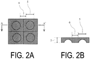
FIG. 2A is a schematic plan view illustrating an example of an array of lenses according to an embodiment of the present invention. -
FIG. 2B is a schematic cross-sectional view illustrating an example of an array of lenses according to an embodiment of the present invention cut at a position A-A' in the plan view ofFIG. 2A . -
FIG. 3 is a schematic view illustrating an array of microlenses fixed on a support tape in the examples. -
FIG. 3A is a schematic plan view illustrating an individualized piece (microlens) obtained by cutting the array of microlenses inFIG. 3 . -
FIG. 3B is a schematic cross-sectional view illustrating an individualized piece (microlens) obtained by cutting the array of microlenses inFIG. 3 . - A method for producing a lens according to an embodiment of the present invention includes cutting an array of lenses at a junction by a method below (= cutting), the array of lenses being fixed on a support tape and having a configuration wherein two or more lenses are two-dimensionally arranged, and these lenses are connected each other via the junction.
- Cutting method: advancing a cutting depth from the side opposite to the side adhered to the support tape to a range from 50% or greater and 99.9% or less of a thickness of the junction, temporarily stopping the advance of the cutting depth when the advance reaches the range, and then cutting the junction to a cutting depth of 100%.
- The cutting in an embodiment of the present invention is for cutting the array of lenses at the junction to individualize the lenses and characterized by cutting the array of lenses by advancing a cutting depth from the side opposite to the side adhered to the support tape to a range from 50% or greater and 99.9% or less of a thickness of the junction, temporarily stopping the advance of the cutting depth when the advance reaches the range, and then cutting the junction to a cutting depth of 100%. Further, in the cutting in an embodiment of the present invention, the operation of stopping the advance of the cutting depth is required to be performed at least once or can be performed twice or more in a range from 50% or greater and 99.9% or less of the thickness of the junction.
- According to the "cutting depth" in the present specification, the depth of the cutting start point at the site to be cut (specifically the junction of the array of lenses) is 0%, and the depth at which the cutting is completed is 100%.
- The array of lenses has a configuration wherein two or more lenses are two-dimensionally arranged, and these lenses are connected each other via a junction. The diameter of the lens is, for example, from 1 to 5 mm. In addition, a width of the junction is, for example, 1 mm or less, preferably from 0.05 to 1 mm, and particularly preferably from 0.05 to 0.5 mm, and a thickness of the junction is, for example, from 0.1 to 1.5 mm.
- Examples of the lens include a microlens, a Fresnel lens, a molded product formed of a plurality of microlenses or Fresnel lenses bonded via a junction, a lenticular lens, and a prism sheet. In addition, the lens includes a lens for a sensor of a mobile electronic device, such as a mobile phone and a smartphone; and a lens for a camera.
- The fracture strain of the array of lenses [more particularly, the fracture strain of the material constituting the array of lenses (for example, a cured product of a curable composition described below)] is, for example, 0.1% or greater, preferably 0.3% or greater, and particularly preferably 0.5% or greater. Further, the upper limit of the fracture strain is, for example, 30%, preferably 20%, particularly preferably 10%, most preferably 5%, and especially preferably 3%. Furthermore, the fracture strain can be measured in accordance with JIS-K7162: 1994 using a test piece 5B mold. The array of lenses with a fracture strain out of the above range, even if the cutting method according to an embodiment of the present invention is applied, may have difficulty in suppressing formation of a gap between the support tape and the lens when a blade or the like reaches the support tape, and it may be difficult to provide an effect of suppressing reduction in optical properties of the lens. In addition, the lens with too small fracture strain may become brittle and may be chipped or cracked during handling.
- The array of lenses is adhered to the support tape at the junction of the lenses and fixed thereon. In addition, in an embodiment of the present invention, the lenses are cut by the above method, and thus even if the adhesive area with the support tape is small, or the lenses are not hydrophilized, the formation of a gap between the support tape and the lens can be suppressed when a blade or the like reaches the support tape, and this can suppress the reduction in optical properties of the lens due to the adhesion of cut chips to the lens surface, the cut chips having entered from the gap.
- The timing to stop the advance of the cutting depth is when the cutting depth is advanced to a range from 50% or greater and 99.9% or less of the thickness of the junction, and the lower limit of the cutting depth is, among them, preferably 60%, more preferably 70%, particularly preferably 80%, most preferably 85%, and especially preferably 90% in that the thrust force that a blade or the like has upon reaching the support tape can be made extremely small. In addition, the upper limit is preferably 99%.
- Further, the timing to stop the advance of the cutting depth is preferably when the thickness of the uncut portion of the junction reaches any one point in a range of, for example, preferably 1 µm or greater, more preferably 2 µm or greater, particularly preferably 3 µm or greater, and most preferably 5 µm or greater. Furthermore, the timing to stop the advance of the cutting depth is preferably when the thickness of the uncut portion of the junction reaches any one point in a range of, for example, preferably 50 µm or less, and among them, more preferably 40 µm or less, particularly preferably 30 µm or less, and most preferably 25 µm or less in that the thrust force that a blade or the like has upon reaching the support tape can be made extremely small.
- In an embodiment of the present invention, the advance of the cutting depth is temporarily stopped at the timing when the cutting depth or the thickness of the uncut portion of the junction is in the above range, and thus the thrust force that a blade or the like has upon reaching the support tape can be reduced to an extremely small level, and the formation of a gap between the support tape and the lens being caused by the thrust force can be suppressed or prevented.
- After the advance of the cutting depth is temporarily stopped, the timing to resume the advance of the cutting depth (or the time to stop the advance of the cutting depth) is preferably when the thrust force that a blade or the like has is relieved, and the time to stop the advance of the cutting depth is, for example, 1 second or longer, preferably 3 seconds or longer, particularly preferably 5 seconds or longer, and most preferably 10 seconds or longer. Further, the upper limit is not particularly limited, but it is not preferred to stop the advance for a long time because it decreases the operating efficiency.
- The cutting means of the array of lenses is not particularly limited, and well-known and commonly used means can be employed, but among others, a blade rotating at high speed is preferably used to perform the cutting.
- In cutting using a blade rotating at high speed, the rotation speed of the blade is, for example, approximately from 10000 to 50000 rpm. In addition, the advance speed of the blade (i.e., the advance speed of the cutting depth) is approximately from 10 to 200 mm/sec.
- Furthermore, when the array of lenses is cut using such as a blade rotating at high speed, frictional heat is generated, and thus it is preferred to cut the array of lenses while cooling in terms of being able to suppress deformation of the lens and reduction in optical properties due to the frictional heat. In an embodiment of the present invention, in particular, it is preferred to perform the array of lenses while water-cooling in terms of being able to remove the frictional heat and concurrently wash away the cut chips, and thereby further reduce the risk of adhesion of cut chips.
- The array of lenses is cut in a fixed state on the support tape. It is preferred to use a re-peelable adhesive tape that can be peeled off when it becomes unnecessary in terms of being able to release the resulting lens from the support tape without damage. Examples of the re-peelable adhesive tape include pressure-sensitive adhesive tapes and adhesive tapes having moderate adhesive force before heat treatment or ultraviolet irradiation is performed (adhesive force of, for example, 3 N/25 mm or greater, preferably 4 N/25 mm or greater, and particularly preferably 5 N/25 mm, and, for example, 20 N/25 mm or less, preferably 18 N/25 mm or less, and particularly preferably 15 N/25 mm or less) and whose adhesion is rapidly reduced or eliminated by performing heat treatment and/or ultraviolet irradiation (i.e., heat-curable adhesive tapes and UV-curable adhesive tapes). In an embodiment of the present invention, among them, a heat-curable adhesive tape or a UV-curable adhesive tape is preferably used in that the lenses can be firmly retained during cutting, the lenses can be readily released by reducing or eliminating the adhesive force when the lenses need to be released, and the damage of the lenses when released can be prevented; and in particular, a UV-curable adhesive tape is preferably used in that the lenses can be swiftly and selectively released (for example, in a case where only a specific lens of a plurality of individualized lenses is desired to be released, the lens can be selectively released by irradiating UV only to the portion of the support tape where the lens to be released is adhered).
- The thickness of the adhesive agent layer of the support tape is, for example, 1 µm or greater, preferably 3 µm or greater, particularly preferably 5 µm or greater, particularly preferably 8 µm or greater, and, for example, 30 µm or less, preferably 18 µm or less, and particularly preferably 15 µm or less. The adhesive agent layer having a thickness less than the above range cannot have sufficient adhesion to fix the lens thereon, and thus the lens may be released during cutting and damaged. In addition, the adhesive agent layer having the thickness greater than the above range has elasticity, and thus the lens may be shaken by the vibration of a blade or the like during cutting, making it difficult to cut the lens accurately.
- In an embodiment of the present invention, for example, commercially available dicing tapes (for example, such as "ELEP HOLDER" series available from Nitto Denko Corporation, "ADWILL" series available from Lintec Corporation, and "ELEGRIP" series available from Denka Adtecs Co., Ltd.) can be suitably used as the support tape.
- When the cutting is advanced to the cutting depth of 100% after the advance of the cutting depth is resumed, a part of the thickness of the support tape may be cut together with the lens, but the support tape is preferably not cut completely. This is because if the support tape is completely cut, for example, the lens may be flown with water when it is cut while being water-cooled and damaged.
- Through the cutting, a lens onto which a support tape cut to the size of the lens is adhered (more particularly, an individualized piece of lens obtained from the array of lenses, the piece including a support tape cut into the size of the lens adhered thereto, wherein the individualized piece obtained from the array of lenses includes a lens concave portion and a peripheral portion thereof) (= a lens with a cut support tape) is obtained. When the lenses are cut at the junction without cutting the support tape completely, lenses in array with a support tape wherein two or more lenses (more particularly, individualized pieces obtained from the array of lenses, the piece being a structure including a lens concave portion and a peripheral portion thereof) in a state of being two-dimensionally arranged are fixed on the support tape are obtained.
- The resulting lens with a cut support tape (or the lenses in array with a support tape) is preferred in that the lens can be released by reducing or eliminating the adhesive force in a manner according to the type of the support tape, and thereby the lens can be released without damage. For example, when an adhesive tape whose adhesive force is rapidly reduced or eliminated by performing heat treatment and/or ultraviolet irradiation is used, the lens is released preferably by performing heat treatment and/or ultraviolet irradiation to reduce or eliminate the adhesive force. The lens released from the cut support tape or the support tape can be suitably used for a lens for a sensor of a mobile electronic device, such as a mobile phone and a smartphone; and a lens for a camera.
- The array of lenses to be subjected to the above cutting is preferably one produced by molding a curable composition using a mold and then curing.
- Accordingly, the method for producing a lens according to an embodiment of the present invention is preferably a method for producing a lens, the method including: molding a curable composition using a mold and then curing to obtain an array of lenses having a configuration wherein two or more lenses are two-dimensionally arranged, and these lenses are connected each other via a junction; fixing the resulting array of lenses on a support tape; and cutting the array of lenses fixed on the support tape at the junction by a method below.
- Cutting method: advancing a cutting depth from the side opposite to the side adhered to the support tape to a range from 50% or greater and 99.9% or less of a thickness of the junction, temporarily stopping the advance of the cutting depth when the advance reaches the range, and then cutting the junction to a cutting depth of 100%.
- The curable composition is preferably one that can be cured by performing heat treatment and/or ultraviolet irradiation to form a cured product with excellent optical properties. In an embodiment of the present invention, among others, a composition capable of forming a cured product with excellent optical properties (i.e., a photocurable composition) is preferred, a composition containing a cationic curable compound as a curable compound is particularly preferred in terms of having excellent curability, and a composition containing at least an epoxy resin as the (cationic) curable compound is most preferred in terms of having excellent curability and providing a cured product (i.e., a lens) with optical properties (in particular, transparency), high hardness, and heat resistance in combination.
- As the epoxy resin, a well-known or commonly used compound having one or more epoxy groups (oxirane ring) in a molecule can be used, and examples thereof include alicyclic epoxy compounds, aromatic epoxy compounds, and aliphatic epoxy compounds. In an embodiment of the present invention, among them, in terms of being able to form a cured product with excellent heat resistance and transparency, a polyfunctional alicyclic epoxy compound having an alicyclic structure and two or more epoxy groups as functional groups in one molecule is preferred.
- Examples of the polyfunctional alicyclic epoxy compounds specifically include:
- (i) a compound having an epoxy group constituted of two adjacent carbon atoms and an oxygen atom that constitute an alicyclic ring (i.e., an alicyclic epoxy group);
- (ii) a compound having an epoxy group directly bonded to an alicyclic ring with a single bond; and
- (iii) a compound having an alicyclic ring and a glycidyl group.
- An example of the above compound (i) having an alicyclic epoxy group includes a compound represented by Formula (i) below.

- In Formula (i) above, X represents a single bond or a linking group (a divalent group having one or more atoms). Examples of the linking group include a divalent hydrocarbon group, an alkenylene group in which some or all of the carbon-carbon double bonds are epoxidized, a carbonyl group, an ether bond, an ester bond, a carbonate group, an amide group, and a group in which a plurality thereof are linked. Note that a substituent (for example, such as an alkyl group) may be bonded to a cyclohexene oxide group in Formula (i).
- Examples of the divalent hydrocarbon group include a linear or branched alkylene group having from 1 to 18 carbons and a divalent alicyclic hydrocarbon group. Examples of the linear or branched alkylene group having from 1 to 18 carbons include a methylene group, a methyl methylene group, a dimethyl methylene group, an ethylene group, a propylene group, and a trimethylene group. Examples of the divalent alicyclic hydrocarbon group include a cycloalkylene group (including a cycloalkylidene group), such as a 1,2-cyclopentylene group, a 1,3-cyclopentylene group, a cyclopentylidene group, a 1,2-cyclohexylene group, a 1,3-cyclohexylene group, a 1,4-cyclohexylene group, and a cyclohexylidene group.
- Examples of the alkenylene group in the alkenylene group in which some or all of the carbon-carbon double bonds are epoxidized (which may be referred to as an "epoxidized alkenylene group") include a linear or branched alkenylene group having from 2 to 8 carbons, such as a vinylene group, a propenylene group, a 1-butenylene group, a 2-butenylene group, a butadienylene group, a pentenylene group, a hexenylene group, a heptenylene group, and an octenylene group. In particular, the epoxidized alkenylene group is preferably an alkenylene group in which all of the carbon-carbon double bonds are epoxidized, and more preferably an alkenylene group having from 2 to 4 carbons in which all of the carbon-carbon double bonds are epoxidized.
- The linking group in the above X is, in particular, preferably a linking group containing an oxygen atom, and specifically, examples thereof include -CO-, -O-CO-O-, -COO-, -O-, -CONH-, and an epoxidized alkenylene group; a group in which a plurality of these groups are linked; and a group in which one or two or more of these groups and one or more of the divalent hydrocarbon groups are linked.
- Representative examples of the compound represented by Formula (i) above include (3,4,3',4'-diepoxy)bicyclohexyl, bis(3,4-epoxycyclohexylmethyl)ether, 1,2-epoxy-1,2-bis(3,4-epoxycyclohexane-1-yl)ethane, 2,2-bis(3,4-epoxycyclohexane-1-yl)propane, 1,2-bis(3,4-epoxycyclohexane-1-yl)ethane, and compounds represented by Formulas (i-1) to (i-10) below. L in Formula (i-5) below is an alkylene group having from 1 to 8 carbons, and, among them, preferably a linear or branched alkylene group having from 1 to 3 carbons, such as a methylene group, an ethylene group, a propylene group, or an isopropylene group. In Formulas (i-5), (i-7), (i-9), and (i-10) below, n1 to n8 each represent an integer from 1 to 30.


- The above compound (i) having an alicyclic epoxy group also includes an epoxy-modified siloxane.
- Examples of the epoxy-modified siloxane include a chain or cyclic polyorganosiloxane having a constituent unit represented by Formula (i') below.

- In Formula (i') above, R1 represents a substituent containing an epoxy group represented by Formula (1a) or (1b) below, and R2 represents an alkyl group or an alkoxy group.


- In the formulas, R1a and R1b are the same or different and represent a linear or branched alkylene group, and examples thereof include a linear or branched alkylene group having from 1 to 10 carbons, such as a methylene group, a methyl methylene group, a dimethyl methylene group, an ethylene group, a propylene group, a trimethylene group, a tetramethylene group, a pentamethylene group, a hexamethylene group, and a decamethylene group.
- The epoxy equivalent (in accordance with JIS K7236) of the epoxy-modified siloxane is, for example, from 100 to 400 and preferably from 150 to 300.
- As the epoxy-modified siloxane, for example, commercially available products can be used, for example, such as an epoxy-modified cyclic polyorganosiloxane represented by Formula (i'-1) below (trade name "X-40-2670", available from Shin-Etsu Chemical Co., Ltd.).

- Examples of the above compound (ii) having an epoxy group directly bonded to an alicyclic ring with a single bond include a compound represented by Formula (ii) below.

- In Formula (ii), R' is a group resulting from elimination of p hydroxyl groups (-OH) from a structural formula of a p-hydric alcohol (p-valent organic group), wherein p and n9 each represent a natural number. Examples of the p-hydric alcohol [R'-(OH)p] include polyhydric alcohols (alcohols having from 1 to 15 carbons), such as 2,2-bis(hydroxymethyl)-1-butanol. Here, p is preferably from 1 to 6, and n9 is preferably from 1 to 30. When p is 2 or greater, n9 in each group in square brackets (the outer brackets) may be the same or different. Examples of the compound represented by Formula (ii) above specifically include 1,2-epoxy-4-(2-oxiranyl)cyclohexane adduct of 2,2-bis(hydroxymethyl)-1-butanol [for example, such as the trade name "EHPE3150" (available from Daicel Corporation)].
- Examples of the above compound (iii) having an alicyclic ring and a glycidyl group include hydrogenated aromatic glycidyl ether-based epoxy compounds, such as a hydrogenated bisphenol A epoxy compound, a hydrogenated bisphenol F epoxy compound, a hydrogenated biphenol epoxy compound, a hydrogenated phenol novolac epoxy compound, a hydrogenated cresol novolac epoxy compound, a hydrogenated cresol novolac epoxy compound of bisphenol A, a hydrogenated naphthalene epoxy compound, and a hydrogenated epoxy compound of an epoxy compound obtained from trisphenol methane.
- The polyfunctional alicyclic epoxy compound is preferably the compound (i) having an alicyclic epoxy group and particularly preferably a compound represented by Formula (i) above (in particular, (3,4,3',4'-diepoxy)bicyclohexyl), in terms of providing a cured product having high surface hardness and excellent transparency.
- The curable composition in an embodiment of the present invention may contain an additional curable compound in addition to the epoxy resin as the curable compound and can contain, for example, one type, or two or more types of cationic curable compounds, such as an oxetane compound and a vinyl ether compound.
- A proportion of the epoxy resin in a total amount (100 wt.%) of the curable compound contained in the curable composition is, for example, 50 wt.% or greater, preferably 60 wt.% or greater, particularly preferably 70 wt.% or greater, and most preferably 80 wt.% or greater, and the upper limit is, for example, 100 wt.% and preferably 90 wt.%.
- In addition, a proportion of the compound (i) having an alicyclic epoxy group in the total amount (100 wt.%) of the curable compound contained in the curable composition is, for example, 20 wt.% or greater, preferably 30 wt.% or greater, and particularly preferably 40 wt.% or greater, and the upper limit is, for example, 70 wt.% and preferably 60 wt.%.
- A proportion of the compound represented by Formula (i) in the total amount (100 wt.%) of the curable compound contained in the curable composition is, for example, 10 wt.% or greater, preferably 15 wt.% or greater, and particularly preferably 20 wt.% or greater, and the upper limit is, for example, 50 wt.% and preferably 40 wt.%.
- The curable composition preferably contains a photopolymerization initiator along with the curable compound and particularly preferably contains a photocationic polymerization initiator. The photocationic polymerization initiator is a compound that initiates curing reaction of the curable compound (in particular, the cationic curable compound) contained in the curable composition by generating an acid with light irradiation and is formed of a cationic moiety that absorbs light and an anionic moiety that serves as a source for generating the acid.
- Examples of the photocationic polymerization initiator include diazonium salt-based compounds, iodonium salt-based compounds, sulfonium salt-based compounds, phosphonium salt-based compounds, selenium salt-based compounds, oxonium salt-based compounds, ammonium salt-based compounds, and bromine salt-based compounds.
- In an embodiment of the present invention, among them, a sulfonium salt-based compound is preferably used in terms of being able to form a cured product with excellent curability. Examples of the cationic moiety of the sulfonium salt-based compound include arylsulfonium ions (in particular, triarylsulfonium ions), such as a (4-hydroxyphenyl)methylbenzylsulfonium ion, a triphenyl sulfonium ion, a diphenyl[4-(phenylthio)phenyl]sulfonium ion, a 4-(4-biphenylthio)phenyl-4-biphenylylphenylsulfonium ion, and a tri-p-tolylsulfonium ion.
- Examples of the anionic moiety of the photocationic polymerization initiator include [(Y)sB(Phf)4-s]-, wherein Y represents a phenyl group or a biphenylyl group, Phf represents a phenyl group in which at least one of hydrogen atoms is substituted with at least one substituent selected from a perfluoroalkyl group, a perfluoroalkoxy group, and a halogen atom, and s is an integer of 0 to 3; BF4 -; [(Rf)tPF6-t]-, wherein Rf represents an alkyl group in which 80% or more of hydrogen atoms are substituted with fluorine atoms, and t represents an integer of 0 to 5; AsF6 -; SbF6 -; and SbF5OH-.
- Commercially available products can be used as the photocationic polymerization initiator in an embodiment of the present invention. Examples thereof include (4-hydroxyphenyl)methylbenzylsulfonium tetrakis(pentafluorophenyl)borate; 4-(4-biphenylylthio)phenyl-4-biphenylylphenylsulfonium tetrakis(pentafluorophenyl)borate; 4-(phenylthio)phenyldiphenylsulfonium phenyltris(pentafluorophenyl)borate; [4-(4-biphenylylthio)phenyl]-4-biphenylylphenylsulfonium phenyltris(pentafluorophenyl)borate; diphenyl[4-(phenylthio)phenyl]sulfonium tris(pentafluoroethyl)trifluorophosphate; diphenyl[4-(phenylthio)phenyl]sulfonium tetrakis(pentafluorophenyl)borate; diphenyl[4-(phenylthio)phenyl]sulfonium hexafluorophosphate; 4-(4-biphenylylthio)phenyl-4-biphenylylphenylsulfonium tris(pentafluoroethyl)trifluorophosphate; bis[4-(diphenylsulfonio)phenyl]sulfide phenyltris(pentafluorophenyl)borate; [4-(2-thioxanthonylthio)phenyl]phenyl-2-thioxanthonylsulfonium phenyltris(pentafluorophenyl)borate; 4-(phenylthio)phenyldiphenylsulfonium hexafluoroantimonate; the trade names "Cyracure UVI-6970", "Cyracure UVI-6974", "Cyracure UVI-6990", and "Cyracure UVI-950" (the above available from Union Carbide Corporation, USA); "Irgacure 250", "Irgacure 261", and "Irgacure 264" (the above available from BASF Corporation); "CG-24-61" (available from Ciba-Geigy Corporation); "Optomer SP-150", "Optomer SP-151", "Optomer SP-170", and "Optomer SP-171" (the above available from ADEKA Corporation); "DAICAT II" (available from Daicel Corporation); "UVAC 1590" and "UVAC 1591" (the above available from Daicel-Cytec Co., Ltd.); "CI-2064", "CI-2639", "CI-2624", "CI-2481", "CI-2734", "CI-2855", "CI-2823", "CI-2758", and "CIT-1682" (the above available from Nippon Soda Co., Ltd.); "PI-2074" (tetrakis(pentafluorophenyl)borate tolylcumyliodonium salt, available from Rhodia Japan Ltd.); "FFC509" (available from 3M Company); "BBI-102", "BBI-101", "BBI-103", "MPI-103", "TPS-103", "MDS-103", "DTS-103", "NAT-103", and "NDS-103" (the above available from Midori Kagaku Co., Ltd.); "CD-1010", "CD-1011", and "CD-1012" (the above available from Sartomer Co., Ltd., USA); and"CPI-100P" and "CPI-101A" (the above available from San-Apro Ltd.).
- The content of the photopolymerization initiator is, for example, in a range from 0.1 to 5.0 parts by weight relative to 100 parts by weight of the curable compound (in particular, the cationic curable compound) contained in the curable composition. The content of the photopolymerization initiator less than the above range may cause curing failure. On the other hand, the content of the photopolymerization initiator greater than the above range tends to cause coloration of the cured product.
- The curable composition in an embodiment of the present invention can be produced by mixing the curable compound, the photopolymerization initiator, and, as necessary, an additional component (for example, such as a solvent, an antioxidant, a surface conditioner, a photosensitizer, an anti-foaming agent, a leveling agent, a coupling agent, a surfactant, a flame retardant, an ultraviolet absorber, and a colorant). The additional component is blended in an amount of, for example, 20 wt.% or less, preferably 10 wt.% or less, and particularly preferably 5 wt.% or less of the total amount of the curable composition.
- A commercially available products can also be used as the curable composition in an embodiment of the present invention, for example, such as trade name "CELVENUS OUH106" (available from Daicel Corporation).
- As the mold, for example, a silicone mold can be used. The mold preferably has a plurality of inverted shapes (i.e., reversed concavo-convex shapes) of the lens (having, for example, 10 or more, preferably 20 or more, particularly preferably 30 or more, and most preferably 50 or more inverted concavo-convex shapes, and the upper limit of the number of the inverted concavo-convex shapes is, for example, 5000 and preferably 2000). Further, the arrangement (two-dimensional arrangement) of the inverted concavo-convex shapes of the lens in the mold is not particularly limited, but, among others, they are preferably arranged two-dimensionally at regular intervals in terms of being able to improve production efficiency. Furthermore, depending on the shape of the lens, a mold having a two-part configuration with an upper mold and a lower mold (for example, a two-part configuration with a mold having an inverted shape of the concave surface of the lens and a mold having an inverted shape of the convex surface of the lens, wherein one mold is an upper mold and the other is a lower mold) can be used.
- A release agent may be coated to the surface of the mold. Examples of the release agent include fluorine-based release agents, silicone-based release agents, and wax-based release agents. One type alone or two or more types thereof in combination can be used.
- Examples of the method for molding the curable composition using a mold include the methods (1) to (3) below.
- (1) A method of coating the curable composition to a substrate, pressing a mold thereon, curing the curable composition, and then detaching the mold;
- (2) A method of coating the curable composition to a mold, pressing a substrate from above, curing the curable composition, and then detaching the mold; and
- (3) A method of coating the curable composition to at least one of an upper mold or a lower mold, combining the upper mold and the lower mold, curing the curable composition, and then detaching the upper mold and the lower mold.
- A substrate having a light transmittance at a wavelength of 400 nm of 90% or higher is preferably used as the substrate, and a substrate made of quartz or glass can be suitably used. Further, the light transmittance at the wavelength is determined using a substrate (thickness: 1 mm) as a test piece and using a spectrophotometer to measure the light transmittance at the wavelength irradiated to the test piece.
- Coating methods, such as a spray method, a spin coating method, and a screen printing method, can be used to coat the curable composition.
- For example, when a photocurable composition is used as the curable composition, the curable composition can be cured by irradiating ultraviolet light thereto. Examples of the light source used to irradiate ultraviolet light include a high-pressure mercury lamp, an ultra-high-pressure mercury lamp, a carbon arc lamp, a xenon lamp, and a metal halide lamp. The irradiation time varies depending on the type of the light source, the distance between the light source and the coated surface, and other conditions, but is several tens of seconds at the longest. The illuminance is approximately from 5 to 200 mW. After the ultraviolet irradiation, the curable composition may be heated (post-curing) as necessary for facilitating curing.
- Hereinafter, the present invention will be described more specifically with reference to examples, but the present invention is not limited by these examples.
- A curable composition (trade name "CELVENUS OUH 106", available from Daicel Corporation, fracture strain of the cured product (measured using a test piece 5B mold in accordance with JIS-K7162: 1994): 0.8%) was coated on a silicone mold, and the mold was closed with a flat silicone mold from above. After the mold was closed, UV was irradiated (80 mW x 30 seconds), and then the mold was opened. An array of microlenses having a configuration wherein 100 microlenses are arranged in 10 lengthwise rows x 10 crosswise rows, and these microlenses are connected each other via a junction was obtained.
- The resulting array of microlenses was adhered to the support tape described in Table 1 below, and lattice-shaped cuts formed of 11 lengthwise cuts and 11 crosswise cuts, each reaching the support tape, were made at the junction (thickness: 0.3 mm) of the array of microlenses by the cutting method below using a blade. Thereby 100 individualized pieces (including the microlens concave portion and the peripheral portion) with a side length of 4.0 mm were obtained (
FIG. 3 ). The resulting 100 individualized pieces were visually observed for appearance, and the number of pieces without adhesion of dirt was counted for evaluating prevention rate of adhesion of cut chips. - The cutting was performed in two stages.
- That is, in the first stage, the cutting was finished in a state where an uncut portion (a portion to be cut) was left in the thickness direction of the junction, and in the second stage, the uncut portion (the portion to be cut) was completely cut. Note that the time from the end of the cutting at the specific cutting site in the first stage to the start of the cutting in the second stage was 25 seconds.
-
Table 1 Cutting (first stage) Cutting (second stage) Prevention rate of adhesion of cut chips (%) Support tape Rotation speed (number of rpm) Cutting speed (mm/s) Thickness of the uncut portion (µm) Cutting depth (%) Rotation speed (number of rpm) Cutting speed (mm/s) Cutting amount in support tape (µm) Example 1 1 12000 50 10 96.7 12000 50 25 84 Example 2 2 12000 50 10 96.7 12000 50 25 61 Example 3 2 30000 100 20 93.3 30000 100 10 88 Example 4 2 30000 100 20 93.3 30000 100 25 87 - An array of microlenses obtained in the same manner as in the examples was adhered to the support tape described in Table 2 below and was cut at the junction using a blade in one stage under the conditions described in Table 2 below. Thereby 100 individualized pieces (including the microlens concave portion and the peripheral portion) with a side length of 4.0 mm were obtained. The resulting individualized pieces were evaluated in the same manner as in the examples for effect of suppressing the adhesion of cut chips.
-
Table 2 Support tape Cutting (in one stage) Suppression rate of adhesion of cut chips (%) Rotation speed (rpm) Cutting speed (mm/s) Cutting depth (%) Cutting amount in support tape (µm) Comparative Example 1 1 12000 50 100 25 6 Comparative Example 2 1 12000 50 100 15 22 Comparative Example 3 1 12000 50 100 55 3 Comparative Example 4 1 30000 50 100 25 2 Comparative Example 5 1 6000 50 100 25 3 Comparative Example 6 1 12000 100 100 25 4 Comparative Example 7 1 12000 20 100 25 0 Comparative Example 8 3 12000 50 100 25 15 Comparative Example 9 4 12000 50 100 25 2 Comparative Example 10 2 12000 50 100 25 26 -
- Tape (1): UV curable dicing tape, available from Lintec Corporation, trade name "ADWILL-D-485 H",
adhesive layer thickness 5 µm, adhesive force 4.9 N/25 mm - Tape (2): UV curable dicing tape, available from Lintec Corporation, trade name "ADWILL-D-611", adhesive layer thickness 15 µm, adhesive force 12.3 N/25 mm
- Tape (3): UV curable dicing tape, available from Denka Adtecs Co., Ltd., trade name "UHP-1515MCE", adhesive layer thickness 15 µm, adhesive force 10.2 N/25 mm
- Tape (4): UV curable dicing tape, available from Denka Adtecs Co., Ltd., trade name "UHP-1510M4",
adhesive layer thickness 10 µm, adhesive force 12.5 N/25 mm - To summarize the above, configurations according to an embodiment of the present invention and variations thereof will be described below.
- (1) A method for producing a lens, the method including cutting an array of lenses at a junction by a method below, the array of lenses being fixed on a support tape and having a configuration wherein two or more lenses are two-dimensionally arranged, and these lenses are connected each other via the junction;
Cutting method: advancing a cutting depth from the side opposite to the side adhered to the support tape to a range of 50% or greater and 99.9% or less of a thickness of the junction, temporarily stopping the advance of the cutting depth when the advance reaches the range, and then cutting the junction to a cutting depth of 100%. - (2) The method for producing a lens according to (1), wherein the array of lenses is cut while being water-cooled.
- (3) The method for producing a lens according to (1) or (2), wherein the array of lenses is adhered to the support tape at the junction of the lenses; a diameter of the lens is from 1 to 5 mm; and a width of the junction is 1 mm or less.
- (4) The method for producing a lens according to any one of (1) to (3), wherein the support tape has an adhesive force of 3 to 20 N/25 mm, and the adhesive force is reduced or eliminated by applying ultraviolet irradiation or heat treatment.
- (5) The method for producing a lens according to any one of (1) to (4), wherein the array of lenses is cut using a blade rotating at high speed.
- (6) The method for producing a lens according to any one of (1) to (5), wherein a curable composition is molded using a mold and then cured to obtain an array of lenses formed of a cured product of the curable composition, and the resulting array of lenses is fixed on the support tape and cut.
- (7) The method for producing a lens according to (6), wherein the curable composition contains a cationic curable compound.
- (8) The method for producing a lens according to (6), wherein the curable composition contains an epoxy resin.
- (9) The method for producing a lens according to (6), wherein the curable composition contains a compound having an alicyclic epoxy group.
- (10) The method for producing a lens according to (6), wherein the curable composition contains a polyfunctional alicyclic epoxy compound.
- (11) The method for producing a lens according to (6), wherein the curable composition contains a compound represented by Formula (i).
- (12) The method for producing a lens according to (6), wherein the curable composition contains at least one compound selected from 3,4-epoxycyclohexylmethyl(3,4-epoxy)cyclohexanecarboxylate, (3,4,3',4'-diepoxy)bicyclohexyl, bis(3,4-epoxycyclohexylmethyl)ether, 1,2-epoxy-1,2-bis(3,4-epoxycyclohexan-1-yl)ethane, 2,2-bis(3,4-epoxycyclohexan-1-yl)propane, and 1,2-bis(3,4-epoxycyclohexan-1-yl)ethane.
- (13) The method for producing a lens according to (6), wherein the curable composition contains at least one type selected from (3,4,3',4'-diepoxy)bicyclohexyl, bis(3,4-epoxycyclohexylmethyl)ether, 1,2-epoxy-1,2-bis(3,4-epoxycyclohexan-1-yl)ethane, 2,2-bis(3,4-epoxycyclohexan-1-yl)propane, and 1,2-bis(3,4-epoxycyclohexan-1-yl)ethane.
- (14) The method for producing a lens according to (6), wherein the curable composition contains an epoxy resin (preferably a compound having an alicyclic epoxy group and particularly preferably a polyfunctional alicyclic epoxy compound), and the proportion of the epoxy resin (preferably a compound having an alicyclic epoxy group and particularly preferably a polyfunctional alicyclic epoxy compound) in a total amount of the curable compound contained in the curable composition is 20 wt.% or greater (preferably 30 wt.% or greater and particularly preferably 40 wt.% or greater, and the upper limit is 70 wt.% and preferably 60 wt.%).
- (15) The method for producing a lens according to (6), wherein the curable composition contains a compound represented by Formula (i), and a proportion of the compound represented by Formula (i) above in the total amount of the curable compound contained in the curable composition is 10 wt.% or greater (preferably 15 wt.% or greater and particularly preferably 20 wt.% or greater).
- (16) The method for producing a lens according to any one of (1) to (15), wherein a fracture strain of the array of lenses according to a method in accordance with JIS-K7162: 1994 is from 0.1 to 30%.
- (17) The method for producing a lens according to any one of (1) to (16), wherein the lens is a microlens, a Fresnel lens, a molded product formed of a plurality of microlenses or Fresnel lenses bonded via a junction, a lenticular lens, or a prism sheet.
- According to the producing method of the present invention, a small thin lens with excellent optical properties can be produced accurately and efficiently. Thus, the method for producing a lens according to the present invention is suitable as a method for producing a lens for a sensor of a mobile electronic device, such as a mobile phone and a smartphone; and a lens for a camera.
-
- 1 Blade rotating at high speed
- 2 Array of lenses
- 3 Support tape
- 3' Support tape cut to size of lens
- 4 Floating between lens and support tape
- 5 Lens concave portion in array of lenses
- 6 Junction of array of lenses
- 7 Thickness of junction of array of lenses
- 8 Array of microlenses fixed on support tape
- 9 Individualized piece obtained from array of lenses
- 10 Lens peripheral portion
- 11 Lens concave portion
- 12 Thickness of junction
Claims (8)
- A method for producing a lens, the method comprising cutting an array of lenses at a junction by a method below, the array of lenses being fixed on a support tape and having a configuration wherein two or more lenses are two-dimensionally arranged, and these lenses are connected each other via the junction;
Cutting method: advancing a cutting depth from the side opposite to the side adhered to the support tape to a range from 50% or greater and 99.9% or less of a thickness of the junction, temporarily stopping the advance of the cutting depth when the advance reaches the range, and then cutting the junction to a cutting depth of 100%. - The method for producing a lens according to claim 1, wherein the array of lenses is cut while being water-cooled.
- The method for producing a lens according to claim 1 or 2, wherein the array of lenses is adhered to the support tape at the junction of the lenses; a diameter of the lens is from 1 to 5 mm; and a width of the junction is 1 mm or less.
- The method for producing a lens according to any one of claims 1 to 3, wherein the support tape has an adhesive force from 3 to 20 N/25 mm, and the adhesive force is reduced or eliminated by applying ultraviolet irradiation or heat treatment.
- The method for producing a lens according to any one of claims 1 to 4, wherein the array of lenses is cut using a blade rotating at high speed.
- The method for producing a lens according to any one of claims 1 to 5, wherein a curable composition is molded using a mold and then cured to obtain an array of lenses formed of a cured product of the curable composition, and the resulting array of lenses is fixed on the support tape and cut.
- The method for producing a lens according to any one of claims 1 to 6, wherein a fracture strain (JIS-K7162: 1994) of the array of lenses is from 0.1 to 30%.
- The method for producing a lens according to any one of claims 1 to 7, wherein the lens is a microlens, a Fresnel lens, a molded product formed of a plurality of microlenses or Fresnel lenses bonded via a junction, a lenticular lens, or a prism sheet.
Applications Claiming Priority (2)
| Application Number | Priority Date | Filing Date | Title |
|---|---|---|---|
| JP2017125298 | 2017-06-27 | ||
| PCT/JP2018/024241 WO2019004227A1 (en) | 2017-06-27 | 2018-06-26 | METHOD FOR PRODUCING LENSES |
Publications (2)
| Publication Number | Publication Date |
|---|---|
| EP3647832A1 true EP3647832A1 (en) | 2020-05-06 |
| EP3647832A4 EP3647832A4 (en) | 2021-04-07 |
Family
ID=64741620
Family Applications (1)
| Application Number | Title | Priority Date | Filing Date |
|---|---|---|---|
| EP18824997.3A Withdrawn EP3647832A4 (en) | 2017-06-27 | 2018-06-26 | Lens production method |
Country Status (6)
| Country | Link |
|---|---|
| US (1) | US20200158920A1 (en) |
| EP (1) | EP3647832A4 (en) |
| JP (1) | JP7071356B2 (en) |
| KR (1) | KR20200018683A (en) |
| CN (1) | CN110799859A (en) |
| WO (1) | WO2019004227A1 (en) |
Family Cites Families (10)
| Publication number | Priority date | Publication date | Assignee | Title |
|---|---|---|---|---|
| JP4347655B2 (en) * | 2003-04-24 | 2009-10-21 | オリンパス株式会社 | Lens array and lens parts |
| JP2006049419A (en) * | 2004-08-02 | 2006-02-16 | Nec Tokin Corp | Dicing method |
| JP2007194469A (en) * | 2006-01-20 | 2007-08-02 | Renesas Technology Corp | Manufacturing method of semiconductor device |
| JP2007273743A (en) * | 2006-03-31 | 2007-10-18 | Kyocera Corp | Semiconductor substrate dicing method and semiconductor substrate |
| CN101772392A (en) * | 2007-08-10 | 2010-07-07 | 柯尼卡美能达精密光学株式会社 | Processing method |
| JP5047243B2 (en) * | 2008-09-26 | 2012-10-10 | シャープ株式会社 | Optical element wafer module, optical element module, optical element module manufacturing method, electronic element wafer module, electronic element module manufacturing method, electronic element module, and electronic information device |
| JP2013003541A (en) * | 2011-06-21 | 2013-01-07 | Konica Minolta Advanced Layers Inc | Compound lens manufacturing method |
| JP5833411B2 (en) * | 2011-11-11 | 2015-12-16 | ルネサスエレクトロニクス株式会社 | Semiconductor device, manufacturing method thereof, and liquid crystal display device |
| WO2013146487A1 (en) * | 2012-03-30 | 2013-10-03 | コニカミノルタ株式会社 | Lens array, lens arrange manufacturing method and optical element manufacturing method |
| JP2017125298A (en) | 2016-01-12 | 2017-07-20 | 株式会社適正地盤設計協会 | Ground improving method and improved ground obtained thereby |
-
2018
- 2018-06-26 JP JP2019526946A patent/JP7071356B2/en active Active
- 2018-06-26 EP EP18824997.3A patent/EP3647832A4/en not_active Withdrawn
- 2018-06-26 US US16/626,685 patent/US20200158920A1/en not_active Abandoned
- 2018-06-26 KR KR1020207001946A patent/KR20200018683A/en not_active Withdrawn
- 2018-06-26 CN CN201880043184.6A patent/CN110799859A/en active Pending
- 2018-06-26 WO PCT/JP2018/024241 patent/WO2019004227A1/en not_active Ceased
Also Published As
| Publication number | Publication date |
|---|---|
| KR20200018683A (en) | 2020-02-19 |
| JPWO2019004227A1 (en) | 2020-04-23 |
| US20200158920A1 (en) | 2020-05-21 |
| EP3647832A4 (en) | 2021-04-07 |
| JP7071356B2 (en) | 2022-05-18 |
| WO2019004227A1 (en) | 2019-01-03 |
| CN110799859A (en) | 2020-02-14 |
Similar Documents
| Publication | Publication Date | Title |
|---|---|---|
| JP7169052B2 (en) | Fresnel lens and manufacturing method thereof | |
| CN104204865B (en) | The manufacture method of lens arra, the manufacture method of lens arra and optical element | |
| US20210001538A1 (en) | Mold-release method for molded article, and mold-release device | |
| US20200158920A1 (en) | Method for producing lens | |
| JP7366215B2 (en) | Mold release method and mold release device for molded products | |
| EP3611544A1 (en) | Optical component array provided with adhesive layer | |
| US11247368B2 (en) | Silicone mold | |
| JP7312806B2 (en) | Optical component and manufacturing method thereof | |
| JP7137325B2 (en) | MOLDING PRODUCT RELEASE METHOD AND MOLD RELEASE DEVICE | |
| JP7201312B2 (en) | Optical component and manufacturing method thereof | |
| JP2023046714A (en) | Lens manufacturing method | |
| JP2021189396A (en) | Manufacturing method of laminated lens structure | |
| JP2021189372A (en) | Manufacturing method of laminated lens structure | |
| JP2021026012A (en) | Light-blocking member | |
| JP2021140055A (en) | Optical member |
Legal Events
| Date | Code | Title | Description |
|---|---|---|---|
| STAA | Information on the status of an ep patent application or granted ep patent |
Free format text: STATUS: THE INTERNATIONAL PUBLICATION HAS BEEN MADE |
|
| PUAI | Public reference made under article 153(3) epc to a published international application that has entered the european phase |
Free format text: ORIGINAL CODE: 0009012 |
|
| STAA | Information on the status of an ep patent application or granted ep patent |
Free format text: STATUS: REQUEST FOR EXAMINATION WAS MADE |
|
| 17P | Request for examination filed |
Effective date: 20200122 |
|
| AK | Designated contracting states |
Kind code of ref document: A1 Designated state(s): AL AT BE BG CH CY CZ DE DK EE ES FI FR GB GR HR HU IE IS IT LI LT LU LV MC MK MT NL NO PL PT RO RS SE SI SK SM TR |
|
| AX | Request for extension of the european patent |
Extension state: BA ME |
|
| DAV | Request for validation of the european patent (deleted) | ||
| DAX | Request for extension of the european patent (deleted) | ||
| A4 | Supplementary search report drawn up and despatched |
Effective date: 20210311 |
|
| RIC1 | Information provided on ipc code assigned before grant |
Ipc: G02B 3/08 20060101ALI20210304BHEP Ipc: B29D 11/00 20060101ALI20210304BHEP Ipc: G02B 3/00 20060101AFI20210304BHEP |
|
| STAA | Information on the status of an ep patent application or granted ep patent |
Free format text: STATUS: THE APPLICATION HAS BEEN WITHDRAWN |
|
| 18W | Application withdrawn |
Effective date: 20210409 |