EP3647742A1 - Power supply circuit and motor control device - Google Patents
Power supply circuit and motor control device Download PDFInfo
- Publication number
- EP3647742A1 EP3647742A1 EP19206193.5A EP19206193A EP3647742A1 EP 3647742 A1 EP3647742 A1 EP 3647742A1 EP 19206193 A EP19206193 A EP 19206193A EP 3647742 A1 EP3647742 A1 EP 3647742A1
- Authority
- EP
- European Patent Office
- Prior art keywords
- voltage
- power supply
- supply circuit
- control device
- sensor
- Prior art date
- Legal status (The legal status is an assumption and is not a legal conclusion. Google has not performed a legal analysis and makes no representation as to the accuracy of the status listed.)
- Granted
Links
Images

Classifications
-
- H—ELECTRICITY
- H02—GENERATION; CONVERSION OR DISTRIBUTION OF ELECTRIC POWER
- H02P—CONTROL OR REGULATION OF ELECTRIC MOTORS, ELECTRIC GENERATORS OR DYNAMO-ELECTRIC CONVERTERS; CONTROLLING TRANSFORMERS, REACTORS OR CHOKE COILS
- H02P27/00—Arrangements or methods for the control of AC motors characterised by the kind of supply voltage
- H02P27/02—Arrangements or methods for the control of AC motors characterised by the kind of supply voltage using supply voltage with constant frequency and variable amplitude
- H02P27/024—Arrangements or methods for the control of AC motors characterised by the kind of supply voltage using supply voltage with constant frequency and variable amplitude using AC supply for only the rotor circuit or only the stator circuit
-
- G—PHYSICS
- G01—MEASURING; TESTING
- G01D—MEASURING NOT SPECIALLY ADAPTED FOR A SPECIFIC VARIABLE; ARRANGEMENTS FOR MEASURING TWO OR MORE VARIABLES NOT COVERED IN A SINGLE OTHER SUBCLASS; TARIFF METERING APPARATUS; MEASURING OR TESTING NOT OTHERWISE PROVIDED FOR
- G01D21/00—Measuring or testing not otherwise provided for
-
- B—PERFORMING OPERATIONS; TRANSPORTING
- B60—VEHICLES IN GENERAL
- B60L—PROPULSION OF ELECTRICALLY-PROPELLED VEHICLES; SUPPLYING ELECTRIC POWER FOR AUXILIARY EQUIPMENT OF ELECTRICALLY-PROPELLED VEHICLES; ELECTRODYNAMIC BRAKE SYSTEMS FOR VEHICLES IN GENERAL; MAGNETIC SUSPENSION OR LEVITATION FOR VEHICLES; MONITORING OPERATING VARIABLES OF ELECTRICALLY-PROPELLED VEHICLES; ELECTRIC SAFETY DEVICES FOR ELECTRICALLY-PROPELLED VEHICLES
- B60L15/00—Methods, circuits, or devices for controlling the traction-motor speed of electrically-propelled vehicles
- B60L15/20—Methods, circuits, or devices for controlling the traction-motor speed of electrically-propelled vehicles for control of the vehicle or its driving motor to achieve a desired performance, e.g. speed, torque, programmed variation of speed
- B60L15/2045—Methods, circuits, or devices for controlling the traction-motor speed of electrically-propelled vehicles for control of the vehicle or its driving motor to achieve a desired performance, e.g. speed, torque, programmed variation of speed for optimising the use of energy
-
- B—PERFORMING OPERATIONS; TRANSPORTING
- B60—VEHICLES IN GENERAL
- B60L—PROPULSION OF ELECTRICALLY-PROPELLED VEHICLES; SUPPLYING ELECTRIC POWER FOR AUXILIARY EQUIPMENT OF ELECTRICALLY-PROPELLED VEHICLES; ELECTRODYNAMIC BRAKE SYSTEMS FOR VEHICLES IN GENERAL; MAGNETIC SUSPENSION OR LEVITATION FOR VEHICLES; MONITORING OPERATING VARIABLES OF ELECTRICALLY-PROPELLED VEHICLES; ELECTRIC SAFETY DEVICES FOR ELECTRICALLY-PROPELLED VEHICLES
- B60L15/00—Methods, circuits, or devices for controlling the traction-motor speed of electrically-propelled vehicles
- B60L15/007—Physical arrangements or structures of drive train converters specially adapted for the propulsion motors of electric vehicles
-
- B—PERFORMING OPERATIONS; TRANSPORTING
- B60—VEHICLES IN GENERAL
- B60L—PROPULSION OF ELECTRICALLY-PROPELLED VEHICLES; SUPPLYING ELECTRIC POWER FOR AUXILIARY EQUIPMENT OF ELECTRICALLY-PROPELLED VEHICLES; ELECTRODYNAMIC BRAKE SYSTEMS FOR VEHICLES IN GENERAL; MAGNETIC SUSPENSION OR LEVITATION FOR VEHICLES; MONITORING OPERATING VARIABLES OF ELECTRICALLY-PROPELLED VEHICLES; ELECTRIC SAFETY DEVICES FOR ELECTRICALLY-PROPELLED VEHICLES
- B60L50/00—Electric propulsion with power supplied within the vehicle
- B60L50/50—Electric propulsion with power supplied within the vehicle using propulsion power supplied by batteries or fuel cells
- B60L50/51—Electric propulsion with power supplied within the vehicle using propulsion power supplied by batteries or fuel cells characterised by AC-motors
-
- B—PERFORMING OPERATIONS; TRANSPORTING
- B62—LAND VEHICLES FOR TRAVELLING OTHERWISE THAN ON RAILS
- B62D—MOTOR VEHICLES; TRAILERS
- B62D5/00—Power-assisted or power-driven steering
- B62D5/04—Power-assisted or power-driven steering electrical, e.g. using an electric servo-motor connected to, or forming part of, the steering gear
- B62D5/0457—Power-assisted or power-driven steering electrical, e.g. using an electric servo-motor connected to, or forming part of, the steering gear characterised by control features of the drive means as such
- B62D5/046—Controlling the motor
-
- B—PERFORMING OPERATIONS; TRANSPORTING
- B62—LAND VEHICLES FOR TRAVELLING OTHERWISE THAN ON RAILS
- B62D—MOTOR VEHICLES; TRAILERS
- B62D5/00—Power-assisted or power-driven steering
- B62D5/04—Power-assisted or power-driven steering electrical, e.g. using an electric servo-motor connected to, or forming part of, the steering gear
- B62D5/0457—Power-assisted or power-driven steering electrical, e.g. using an electric servo-motor connected to, or forming part of, the steering gear characterised by control features of the drive means as such
- B62D5/046—Controlling the motor
- B62D5/0463—Controlling the motor calculating assisting torque from the motor based on driver input
-
- G—PHYSICS
- G05—CONTROLLING; REGULATING
- G05F—SYSTEMS FOR REGULATING ELECTRIC OR MAGNETIC VARIABLES
- G05F1/00—Automatic systems in which deviations of an electric quantity from one or more predetermined values are detected at the output of the system and fed back to a device within the system to restore the detected quantity to its predetermined value or values, i.e. retroactive systems
- G05F1/10—Regulating voltage or current
- G05F1/12—Regulating voltage or current wherein the variable actually regulated by the final control device is AC
- G05F1/24—Regulating voltage or current wherein the variable actually regulated by the final control device is AC using bucking or boosting transformers as final control devices
- G05F1/253—Regulating voltage or current wherein the variable actually regulated by the final control device is AC using bucking or boosting transformers as final control devices the transformers including plural windings in series between source and load
-
- H—ELECTRICITY
- H02—GENERATION; CONVERSION OR DISTRIBUTION OF ELECTRIC POWER
- H02M—APPARATUS FOR CONVERSION BETWEEN AC AND AC, BETWEEN AC AND DC, OR BETWEEN DC AND DC, AND FOR USE WITH MAINS OR SIMILAR POWER SUPPLY SYSTEMS; CONVERSION OF DC OR AC INPUT POWER INTO SURGE OUTPUT POWER; CONTROL OR REGULATION THEREOF
- H02M3/00—Conversion of DC power input into DC power output
- H02M3/02—Conversion of DC power input into DC power output without intermediate conversion into AC
- H02M3/04—Conversion of DC power input into DC power output without intermediate conversion into AC by static converters
- H02M3/10—Conversion of DC power input into DC power output without intermediate conversion into AC by static converters using discharge tubes with control electrode or semiconductor devices with control electrode
- H02M3/145—Conversion of DC power input into DC power output without intermediate conversion into AC by static converters using discharge tubes with control electrode or semiconductor devices with control electrode using devices of a triode or transistor type requiring continuous application of a control signal
- H02M3/155—Conversion of DC power input into DC power output without intermediate conversion into AC by static converters using discharge tubes with control electrode or semiconductor devices with control electrode using devices of a triode or transistor type requiring continuous application of a control signal using semiconductor devices only
- H02M3/156—Conversion of DC power input into DC power output without intermediate conversion into AC by static converters using discharge tubes with control electrode or semiconductor devices with control electrode using devices of a triode or transistor type requiring continuous application of a control signal using semiconductor devices only with automatic control of output voltage or current, e.g. switching regulators
- H02M3/158—Conversion of DC power input into DC power output without intermediate conversion into AC by static converters using discharge tubes with control electrode or semiconductor devices with control electrode using devices of a triode or transistor type requiring continuous application of a control signal using semiconductor devices only with automatic control of output voltage or current, e.g. switching regulators including plural semiconductor devices as final control devices for a single load
- H02M3/1588—Conversion of DC power input into DC power output without intermediate conversion into AC by static converters using discharge tubes with control electrode or semiconductor devices with control electrode using devices of a triode or transistor type requiring continuous application of a control signal using semiconductor devices only with automatic control of output voltage or current, e.g. switching regulators including plural semiconductor devices as final control devices for a single load comprising at least one synchronous rectifier element
-
- Y—GENERAL TAGGING OF NEW TECHNOLOGICAL DEVELOPMENTS; GENERAL TAGGING OF CROSS-SECTIONAL TECHNOLOGIES SPANNING OVER SEVERAL SECTIONS OF THE IPC; TECHNICAL SUBJECTS COVERED BY FORMER USPC CROSS-REFERENCE ART COLLECTIONS [XRACs] AND DIGESTS
- Y02—TECHNOLOGIES OR APPLICATIONS FOR MITIGATION OR ADAPTATION AGAINST CLIMATE CHANGE
- Y02T—CLIMATE CHANGE MITIGATION TECHNOLOGIES RELATED TO TRANSPORTATION
- Y02T10/00—Road transport of goods or passengers
- Y02T10/60—Other road transportation technologies with climate change mitigation effect
- Y02T10/70—Energy storage systems for electromobility, e.g. batteries
-
- Y—GENERAL TAGGING OF NEW TECHNOLOGICAL DEVELOPMENTS; GENERAL TAGGING OF CROSS-SECTIONAL TECHNOLOGIES SPANNING OVER SEVERAL SECTIONS OF THE IPC; TECHNICAL SUBJECTS COVERED BY FORMER USPC CROSS-REFERENCE ART COLLECTIONS [XRACs] AND DIGESTS
- Y02—TECHNOLOGIES OR APPLICATIONS FOR MITIGATION OR ADAPTATION AGAINST CLIMATE CHANGE
- Y02T—CLIMATE CHANGE MITIGATION TECHNOLOGIES RELATED TO TRANSPORTATION
- Y02T10/00—Road transport of goods or passengers
- Y02T10/60—Other road transportation technologies with climate change mitigation effect
- Y02T10/72—Electric energy management in electromobility
Definitions
- the present invention relates to a power supply circuit and a motor control device.
- JP 2009-208504 A discloses a torque sensor that detects steering torque.
- Such a torque sensor is operated by electric power supplied from a battery. Specifically, voltage of the electric power supplied from the battery is lowered to a standard voltage by a standard voltage generation circuit, and an operation voltage for driving the torque sensor is generated from the standard voltage by a sensor power supply circuit.
- the sensor power supply circuit applies the operation voltage to the torque sensor, whereby the torque sensor is operated.
- An object of the present invention is to provide a power supply circuit and a motor control device that can suppress complexity in management of the power supply circuit.
- a power supply circuit includes a voltage application unit configured to apply an operation voltage based on a standard voltage to a sensor that outputs an output value based on a detected state quantity, and a switching unit configured to switch the standard voltage of the voltage application unit so that the standard voltage becomes a voltage required to operate the sensor in accordance with a type of the sensor.
- the standard voltage of the voltage application unit is switched in accordance with the type of the sensor by the switching unit, an appropriate operation voltage corresponding to the type of the sensor can be applied by the voltage application unit. Since the operation voltage can be applied in accordance with the type of the sensor, the number of types of power supply circuits to be prepared can be reduced, and the complexity in management of the power supply circuit can be suppressed.
- the power supply circuit connected to a control device may further include a first standard voltage generation circuit configured to generate a first standard voltage.
- One of the sensors may be a first sensor configured to output a voltage based on the detected state quantity to the control device.
- the switching unit may be configured to select, as the standard voltage of the voltage application unit, the first standard voltage that is generated by the first standard voltage generation circuit and having the same potential as a power supply voltage of the control device that is generated from a battery voltage, when the voltage application unit applies an operation voltage to the first sensor.
- the power supply circuit connected to the control device may further include a second standard voltage generation circuit configured to generate a second standard voltage.
- One of the sensors may be a second sensor configured to output the detected state quantity as a digital value.
- the switching unit may be configured to select, as the standard voltage of the voltage application unit, the second standard voltage generated from the battery voltage generated by the second standard voltage generation circuit, when the voltage application unit applies an operation voltage to the second sensor.
- the operation voltage required to operate a sensor to which power is supplied from a power supply circuit may vary depending on the type of the sensor. Therefore, the switching unit is configured to select an appropriate standard voltage as the standard voltage of the voltage application unit depending on the type of the sensor.
- the voltage application unit can apply to the sensor the operation voltage in accordance with the first standard voltage or the second standard voltage, that is, the operation voltage in accordance with the type of the sensor. For example, when the voltage application unit applies the operation voltage to the first sensor, the switching unit can select the first standard voltage as the standard voltage. For example, when the voltage application unit applies the operation voltage to the second sensor, the switching unit can select the second standard voltage as the standard voltage.
- a second aspect of the present invention relates to a motor control device including the power supply circuit according to the first aspect and a control device connected to the power supply circuit.
- a start switch of a vehicle When a start switch of a vehicle is turned on, power is supplied from a battery to the control device.
- the control device is configured to store identification information corresponding to the type of the sensor and control driving of a motor.
- the control device is configured to output the identification information corresponding to the type of the sensor connected to the power supply circuit to the switching unit when the start switch is turned on.
- the switching unit is configured to switch the standard voltage of the voltage application unit based on the identification information.
- the control device is configured to output to the switching unit identification information in accordance with the type of the sensor connected to the power supply circuit when the start switch of the vehicle is turned on.
- the switching unit can switch the standard voltage of the voltage application unit to the standard voltage corresponding to the type of the sensor based on the identification information, the operation voltage applied to the sensor can be varied in accordance with the type of the sensor. Since the operation voltage can be applied in accordance with the type of the sensor, the number of types of power supply circuits to be prepared can be reduced, and the complexity in management of the power supply circuit can be suppressed.
- a third aspect of the present invention relates to a motor control device including the power supply circuit according to the first aspect and a control device connected to the power supply circuit.
- a start switch of a vehicle When a start switch of a vehicle is turned on, power is supplied from a battery to the control device.
- the control device is configured to store identification information corresponding to the type of the sensor and control driving of a motor.
- the power supply circuit includes a terminal unit configured to output to the switching unit an identification state for identifying the type of the sensor.
- the switching unit is configured to switch the standard voltage of the voltage application unit based on the identification state.
- the switching unit can switch the standard voltage of the voltage application unit based on the identification state corresponding to the type of the sensor. Since the terminal unit for outputting the identification state is provided in the power supply circuit, it is not necessary to provide a configuration for outputting the identification state in the control device. Thus, the configuration of the control device can be simplified.
- FIG. 1 is a diagram schematically showing a motor control device 1.
- FIG. 1 illustration of resistors and the like is omitted for ease of explanation.
- the motor control device 1 includes a microcomputer 10 and a power supply circuit 20.
- the microcomputer 10 is an example of a control device.
- the microcomputer 10 and the power supply circuit 20 are operated by a battery voltage V supplied from a battery 30.
- the microcomputer 10 of the motor control device 1 is connected to a motor 40 and controls operation of the motor 40 based on outputs from various sensors. As one of the various sensors, for example, a torque sensor 50 is employed.
- An ignition switch 31 is provided between the battery 30 and the power supply circuit 20.
- the ignition switch 31 serves as a start switch that switches between application and interruption of power supplied from the battery 30.
- the driver operates a switch provided on a vehicle
- the ignition switch 31 is turned on and turned off.
- the ignition switch 31 is turned on, power is applied between the battery 30 and the power supply circuit 20 through the ignition switch 31.
- the ignition switch 31 is turned off, power is interrupted between the battery 30 and the power supply circuit 20 through the ignition switch 31.
- the microcomputer 10 controls power supplied to the motor 40 when the ignition switch 31 is turned on.
- the microcomputer 10 is composed of, for example, a microprocessing unit.
- the power supply circuit 20 is connected to the microcomputer 10.
- the power supply circuit 20 is composed by packaging a logic circuit combining an electronic circuit, a flip-flop, and the like.
- the power supply circuit 20 is a so-called application specific integrated circuit (ASIC).
- the microcomputer 10 reads a program stored in its storage unit 11 and executes a calculation in accordance with the program.
- the torque sensor 50 is connected to the power supply circuit 20.
- the torque sensor 50 is a sensor that detects a steering torque Th applied to a steering shaft of a steering system, for example.
- power is supplied to the torque sensor 50. That is, when the ignition switch 31 is turned on, power is supplied to the torque sensor 50, whereby the torque sensor 50 is operated.
- no power is supplied to the torque sensor 50. That is, when the ignition switch 31 is turned off, no power is supplied to the torque sensor 50, whereby operation of the torque sensor 50 is stopped.
- the torque sensor 50 is connected to the microcomputer 10.
- the torque sensor 50 outputs an output signal based on the detected steering torque Th to the microcomputer 10.
- torque sensors 50 that require different operation voltages Vt for their operation.
- the motor control device 1 is configured such that different operation voltages Vt can be applied to the torque sensor 50 depending on the type of the torque sensor 50.
- the storage unit 11 of the microcomputer 10 stores identification information I that is information corresponding to the type of the torque sensor 50 connected to the motor control device 1 of the present embodiment.
- the identification information I of the present embodiment is information especially indicating an output mode of the output signal, more specifically, whether the output signal of the torque sensor 50 is an analog signal or a digital signal.
- the microcomputer 10 outputs the identification information I to the power supply circuit 20 at the timing when the ignition switch 31 is turned on.
- the microcomputer 10 grasps the output mode of the output signal of the torque sensor 50 from a communication standard of a connector of the torque sensor 50 connected to a connector of the microcomputer 10.
- the microcomputer 10 When the output mode of the output signal of the torque sensor 50 is an analog value, the microcomputer 10 outputs, for example, "0" as the identification information I for generating the operation voltage Vt corresponding to the torque sensor 50 that outputs an analog value. Further, when the output mode of the output signal of the torque sensor 50 is a digital value, the microcomputer 10 outputs, for example, "1" as the identification information I for generating the operation voltage Vt corresponding to the torque sensor 50 that outputs a digital value.
- An example of a first sensor described in the claims is the torque sensor 50 that outputs an analog value
- an example of a second sensor described in the claims is the torque sensor 50 that outputs a digital value.
- the power supply circuit 20 includes a voltage application unit 60 and a switching unit 70, and is connected to a reference voltage generation unit 80 and a power supply voltage generation unit 90.
- the reference voltage generation unit 80 generates a reference voltage Vref that is a constant voltage from the battery voltage V of the battery 30.
- An example of a second standard voltage generation circuit described in the claims is the reference voltage generation unit 80, and an example of a second standard voltage described in the claims is the reference voltage Vref.
- the power supply voltage generation unit 90 generates a power supply voltage Vcc that is a constant voltage from the reference voltage Vref generated by the reference voltage generation unit 80.
- the microcomputer 10 is operated based on the power supply voltage Vcc generated by the power supply voltage generation unit 90.
- An example of a first standard voltage generation circuit described in the claims is the power supply voltage generation unit 90, and an example of a first standard voltage described in the claims is the power supply voltage Vcc.
- the switching unit 70 is a multiplexer that receives two or more inputs and outputs one signal. Specifically, the switching unit 70 acquires the reference voltage Vref generated by the reference voltage generation unit 80 and the power supply voltage Vcc generated by the power supply voltage generation unit 90. The switching unit 70 acquires the identification information I output from the microcomputer 10. Based on the acquired identification information I, the switching unit 70 outputs either the reference voltage Vref or the power supply voltage Vcc as a standard voltage. Specifically, the switching unit 70 outputs the power supply voltage Vcc when the identification information I is "0", and outputs the reference voltage Vref when the identification information I is "1". Thus, the switching unit 70 outputs either the reference voltage Vref or the power supply voltage Vcc selected in accordance with the type of the torque sensor 50.
- the voltage application unit 60 applies the operation voltage Vt to the torque sensor 50 using the battery voltage V supplied from the battery 30 through the ignition switch 31.
- the voltage application unit 60 lowers the battery voltage V supplied from the battery 30 based on either the reference voltage Vref or the power supply voltage Vcc selected by the switching unit 70, thereby generating the operation voltage Vt of the torque sensor 50.
- the voltage application unit 60 includes an operational amplifier 61 and a transistor 62.
- the transistor 62 is provided on a power supply line L between the ignition switch 31 and the torque sensor 50.
- the transistor 62 is a metal-oxide-semiconductor field-effect transistor (MOSFET).
- a source of the transistor 62 is connected to the ignition switch 31 side, which is a positive side of the battery 30, and a drain of the transistor 62 is connected to the torque sensor 50 side.
- a gate of the transistor 62 is connected to an output terminal of the operational amplifier 61.
- An inverting input terminal of the operational amplifier 61 is connected to the output terminal of the switching unit 70.
- a non-inverting input terminal of the operational amplifier 61 is connected to a node N1 provided on the power supply line L between the transistor 62 and the torque sensor 50.
- the operational amplifier 61 By providing the operational amplifier 61 in this manner, negative feedback of the operational amplifier 61 is performed.
- the operational amplifier 61 outputs a gate voltage Vg from its output terminal.
- the gate voltage Vg is a voltage based on a deviation between a voltage input to the inverting input terminal and a feedback voltage Vr input to the non-inverting input terminal.
- the gate voltage Vg may be larger than, smaller than, or equal to the deviation between the voltage input to the inverting input terminal and the feedback voltage Vr input to the non-inverting input terminal.
- the operation voltage Vt of the torque sensor 50 is generated from the battery voltage V of the battery 30 by switching on/off of the transistor 62 in accordance with the gate voltage Vg applied to the gate of the transistor 62. Specifically, when the gate voltage Vg based on a deviation between the power supply voltage Vcc and the feedback voltage Vr is applied to the gate, the transistor 62 lowers the battery voltage V of the battery 30 to generate the operation voltage Vt of the torque sensor 50 that outputs an analog value. When the gate voltage Vg based on the deviation between the reference voltage Vref and the feedback voltage Vr is applied to the gate, the transistor 62 may lower the battery voltage V of the battery 30 to generate the operation voltage Vt of the torque sensor 50 that outputs a digital value.
- the voltage application unit 60 can apply to the torque sensor 50 the operation voltage Vt in accordance with the type of the torque sensor 50 based on the power supply voltage Vcc or the reference voltage Vref, which is the standard voltage of the voltage application unit 60 applied by the switching unit 70.
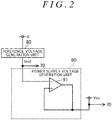
- FIG. 2 schematically shows the reference voltage generation unit 80 and the power supply voltage generation unit 90.
- illustration of resistors and the like is omitted for ease of explanation.
- the power supply voltage generation unit 90 generates the power supply voltage Vcc using the reference voltage Vref generated by the reference voltage generation unit 80.
- the reference voltage generation unit 80 generates the reference voltage Vref that is a constant voltage from the battery voltage V by using a pre-regulator or by resistance division.
- the power supply voltage generation unit 90 includes an operational amplifier 91.
- An inverting input terminal of the operational amplifier 91 is connected to an output terminal of the reference voltage generation unit 80.
- the output terminal of the operational amplifier 91 is connected to the non-inverting input terminal of the operational amplifier 91 so that the output from the output terminal of the operational amplifier 91 serves as the input of the non-inverting input terminal of the operational amplifier 91.
- the operational amplifier 91 By providing the operational amplifier 91 in this manner, negative feedback of the operational amplifier 91 is performed.
- the operational amplifier 91 outputs from the output terminal a voltage based on a deviation between the reference voltage Vref and the voltage input from the non-inverting input terminal of the operational amplifier 91.
- the power supply voltage Vcc that is a constant voltage is acquired. Accordingly, the power supply voltage generation unit 90 generates the power supply voltage Vcc using the reference voltage Vref.
- a motor control device according to a second embodiment will be described. Here, the difference from the first embodiment will be mainly described.
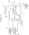
- FIG. 3 shows the power supply circuit 20 of the motor control device 1.
- the power supply circuit 20 has a terminal unit 21.
- the terminal unit 21 is switched to a predetermined identification state S based on an operation of a switch provided in the power supply circuit 20 performed by the operator.
- the operator switches the identification state S of the switch in accordance with the type of the torque sensor 50.
- the terminal unit 21 is switched to, for example, an analog switching position as the identification state S.
- the terminal unit 21 is switched to, for example, a digital switching position as the identification state S.
- the switching unit 70 Based on the identification state S, the switching unit 70 outputs either the reference voltage Vref or the power supply voltage Vcc as the standard voltage. Specifically, the switching unit 70 outputs the power supply voltage Vcc when the identification state S is the analog switching position, and outputs the reference voltage Vref when the identification state S is the digital switching position. Thus, the switching unit 70 outputs either the reference voltage Vref or the power supply voltage Vcc selected in accordance with the type of the torque sensor 50.
- the switching unit 70 can switch the standard voltage of the voltage application unit 60 based on the identification state S corresponding to the type of the torque sensor 50.
- the power supply circuit 20 is provided with the terminal unit 21 for outputting the identification state S.
- the configuration of the microcomputer 10 can be simplified because it is not necessary to provide the microcomputer 10 with a configuration for outputting the identification state S.
- the power supply voltage generation unit 90 generates the power supply voltage Vcc using the reference voltage Vref generated by the reference voltage generation unit 80, but the present invention is not limited thereto.
- the power supply voltage generation unit 90 may generate the power supply voltage Vcc that is a constant voltage from the battery voltage V by using a pre-regulator or by resistance division.
- the reference voltage generation unit 80 may generate the reference voltage Vref using the power supply voltage Vcc generated by the power supply voltage generation unit 90.
- the voltage application unit 60 is composed by the operational amplifier 61 and the transistor 62, but the present invention is not limited thereto.
- the voltage application unit 60 may be composed by resistance division or the like.
- the identification information I and the identification state S are information indicating "0" or "1", but the present invention is not limited thereto.
- the identification information I and the identification state S may be character strings indicating standards of the torque sensor 50. In this case, the switching unit 70 switches the standard voltage by reading the character strings of the identification information I and the identification state S.
- the microcomputer 10 outputs the identification information I to the switching unit 70 at the timing when the ignition switch 31 is turned on.
- the present invention is not limited thereto.
- the microcomputer 10 may intermittently output the identification information I to the switching unit 70 while the ignition switch 31 is turned on.
- the power supply circuit 20 may include the reference voltage generation unit 80 and the power supply voltage generation unit 90.
- the switching unit 70 selects one of the two voltages, that is, the reference voltage Vref and the power supply voltage Vcc, based on the identification information I and the identification state S, and outputs the selected voltage as the standard voltage.
- the present invention is not limited thereto.
- the switching unit 70 may acquire three or more voltages, select any one of the three or more acquired voltages based on the identification information I and the identification state S, and output the selected voltage as the standard voltage.
- the switching unit 70 switches the standard voltage of the voltage application unit 60 based on the identification information I and the identification state S corresponding to the type of the output mode of the output signal of the torque sensor 50.
- the present invention is not limited thereto.
- the operation voltage Vt required for operation of the torque sensor 50 may differ.
- a torque sensor 50 with different specifications and a torque sensor 50 with different measurement targets for measuring the steering torque Th may require different operation voltages Vt for operation of the torque sensor 50 even though the output mode is the same.
- a plurality of standard voltages corresponding to the different specifications and the different measurement targets of the torque sensor 50 may be input to the switching unit 70, and the switching unit 70 may switch the standard voltage of the voltage application unit 60 based on the identification information I and the identification state S.
- torque sensors 50 having different methods of detecting the steering torque Th, such as a magnetostrictive sensor and a piezoelectric sensor.
- the operation voltages Vt required for operation of such torque sensors 50 may differ. Even in such a case, a plurality of standard voltages corresponding to methods of detecting the steering torque Th may be input to the switching unit 70, and the switching unit 70 may switch the standard voltage of the voltage application unit 60 based on the identification information I and the identification state S.
- the operation voltage Vt is applied to the torque sensor 50 by the voltage application unit 60 of the power supply circuit 20, but the present invention is not limited thereto.
- the power supply circuit 20 may apply the operation voltage Vt to a rotation angle sensor or to a vehicle speed sensor.
- the motor control device 1 may control the motor based on the rotation angle sensor.
- a vehicle on which the motor control device 1 of the embodiment is mounted may be a so-called internal combustion engine vehicle that employs an engine as a vehicle drive source, or a so-called electric vehicle that employs a motor as the vehicle drive source.
- the start switch is a switch that starts the motor serving as the vehicle drive source.
Landscapes
- Engineering & Computer Science (AREA)
- Power Engineering (AREA)
- Transportation (AREA)
- Mechanical Engineering (AREA)
- Physics & Mathematics (AREA)
- General Physics & Mathematics (AREA)
- Chemical & Material Sciences (AREA)
- Combustion & Propulsion (AREA)
- Life Sciences & Earth Sciences (AREA)
- Sustainable Development (AREA)
- Sustainable Energy (AREA)
- Electromagnetism (AREA)
- Radar, Positioning & Navigation (AREA)
- Automation & Control Theory (AREA)
- Power Steering Mechanism (AREA)
- Control Of Electric Motors In General (AREA)
- Steering Control In Accordance With Driving Conditions (AREA)
Abstract
Description
- The present invention relates to a power supply circuit and a motor control device.
- Japanese Unexamined Patent Application Publication No.
2009-208504 JP 2009-208504 A - There are various types of torque sensors that require different operation voltages for their operation. Since it is necessary to prepare a plurality of types of sensor power supply circuits in accordance with the types of torque sensors, management of the power supply circuit is complicated.
- An object of the present invention is to provide a power supply circuit and a motor control device that can suppress complexity in management of the power supply circuit.
- A power supply circuit according to a first aspect of the present invention includes a voltage application unit configured to apply an operation voltage based on a standard voltage to a sensor that outputs an output value based on a detected state quantity, and a switching unit configured to switch the standard voltage of the voltage application unit so that the standard voltage becomes a voltage required to operate the sensor in accordance with a type of the sensor.
- According to the above configuration, since the standard voltage of the voltage application unit is switched in accordance with the type of the sensor by the switching unit, an appropriate operation voltage corresponding to the type of the sensor can be applied by the voltage application unit. Since the operation voltage can be applied in accordance with the type of the sensor, the number of types of power supply circuits to be prepared can be reduced, and the complexity in management of the power supply circuit can be suppressed.
- According to the first aspect of the present invention, the power supply circuit connected to a control device may further include a first standard voltage generation circuit configured to generate a first standard voltage. One of the sensors may be a first sensor configured to output a voltage based on the detected state quantity to the control device. The switching unit may be configured to select, as the standard voltage of the voltage application unit, the first standard voltage that is generated by the first standard voltage generation circuit and having the same potential as a power supply voltage of the control device that is generated from a battery voltage, when the voltage application unit applies an operation voltage to the first sensor.
- According to the first aspect of the present invention, the power supply circuit connected to the control device may further include a second standard voltage generation circuit configured to generate a second standard voltage. One of the sensors may be a second sensor configured to output the detected state quantity as a digital value. The switching unit may be configured to select, as the standard voltage of the voltage application unit, the second standard voltage generated from the battery voltage generated by the second standard voltage generation circuit, when the voltage application unit applies an operation voltage to the second sensor.
- The operation voltage required to operate a sensor to which power is supplied from a power supply circuit may vary depending on the type of the sensor. Therefore, the switching unit is configured to select an appropriate standard voltage as the standard voltage of the voltage application unit depending on the type of the sensor. Thereby, the voltage application unit can apply to the sensor the operation voltage in accordance with the first standard voltage or the second standard voltage, that is, the operation voltage in accordance with the type of the sensor. For example, when the voltage application unit applies the operation voltage to the first sensor, the switching unit can select the first standard voltage as the standard voltage. For example, when the voltage application unit applies the operation voltage to the second sensor, the switching unit can select the second standard voltage as the standard voltage.
- A second aspect of the present invention relates to a motor control device including the power supply circuit according to the first aspect and a control device connected to the power supply circuit. When a start switch of a vehicle is turned on, power is supplied from a battery to the control device. The control device is configured to store identification information corresponding to the type of the sensor and control driving of a motor. The control device is configured to output the identification information corresponding to the type of the sensor connected to the power supply circuit to the switching unit when the start switch is turned on. The switching unit is configured to switch the standard voltage of the voltage application unit based on the identification information.
- According to the above configuration, the control device is configured to output to the switching unit identification information in accordance with the type of the sensor connected to the power supply circuit when the start switch of the vehicle is turned on. Thereby, since the switching unit can switch the standard voltage of the voltage application unit to the standard voltage corresponding to the type of the sensor based on the identification information, the operation voltage applied to the sensor can be varied in accordance with the type of the sensor. Since the operation voltage can be applied in accordance with the type of the sensor, the number of types of power supply circuits to be prepared can be reduced, and the complexity in management of the power supply circuit can be suppressed.
- A third aspect of the present invention relates to a motor control device including the power supply circuit according to the first aspect and a control device connected to the power supply circuit. When a start switch of a vehicle is turned on, power is supplied from a battery to the control device. The control device is configured to store identification information corresponding to the type of the sensor and control driving of a motor. The power supply circuit includes a terminal unit configured to output to the switching unit an identification state for identifying the type of the sensor. The switching unit is configured to switch the standard voltage of the voltage application unit based on the identification state.
- According to the above configuration, the switching unit can switch the standard voltage of the voltage application unit based on the identification state corresponding to the type of the sensor. Since the terminal unit for outputting the identification state is provided in the power supply circuit, it is not necessary to provide a configuration for outputting the identification state in the control device. Thus, the configuration of the control device can be simplified.
- The foregoing and further features and advantages of the present invention will become apparent from the following description of example embodiments with reference to the accompanying drawings, wherein like numerals are used to represent like elements and wherein:
-
FIG. 1 is a block diagram showing a schematic configuration of a motor control device according to a first embodiment; -
FIG. 2 is a block diagram showing a schematic configuration of a reference voltage generation unit and a power supply voltage generation unit; and -
FIG. 3 is a block diagram showing a schematic configuration of a power supply circuit according to a second embodiment. - Hereinafter, a motor control device according to a first embodiment of the present invention is described.
FIG. 1 is a diagram schematically showing amotor control device 1. InFIG. 1 , illustration of resistors and the like is omitted for ease of explanation. - As shown in
FIG. 1 , themotor control device 1 includes amicrocomputer 10 and apower supply circuit 20. Themicrocomputer 10 is an example of a control device. Themicrocomputer 10 and thepower supply circuit 20 are operated by a battery voltage V supplied from abattery 30. Themicrocomputer 10 of themotor control device 1 is connected to amotor 40 and controls operation of themotor 40 based on outputs from various sensors. As one of the various sensors, for example, atorque sensor 50 is employed. - An
ignition switch 31 is provided between thebattery 30 and thepower supply circuit 20. Theignition switch 31 serves as a start switch that switches between application and interruption of power supplied from thebattery 30. When the driver operates a switch provided on a vehicle, theignition switch 31 is turned on and turned off. When theignition switch 31 is turned on, power is applied between thebattery 30 and thepower supply circuit 20 through theignition switch 31. When theignition switch 31 is turned off, power is interrupted between thebattery 30 and thepower supply circuit 20 through theignition switch 31. - When power is applied between the
battery 30 and thepower supply circuit 20 through theignition switch 31, power is supplied to themicrocomputer 10. That is, when theignition switch 31 is turned on, power is supplied to themicrocomputer 10, whereby themicrocomputer 10 is operated. Meanwhile, when power is interrupted between thebattery 30 and thepower supply circuit 20 through theignition switch 31, no power is supplied to themicrocomputer 10. That is, when theignition switch 31 is turned off, no power is supplied to themicrocomputer 10, whereby operation of themicrocomputer 10 is stopped. - The
microcomputer 10 controls power supplied to themotor 40 when theignition switch 31 is turned on. Themicrocomputer 10 is composed of, for example, a microprocessing unit. Thepower supply circuit 20 is connected to themicrocomputer 10. Thepower supply circuit 20 is composed by packaging a logic circuit combining an electronic circuit, a flip-flop, and the like. Thepower supply circuit 20 is a so-called application specific integrated circuit (ASIC). Themicrocomputer 10 reads a program stored in itsstorage unit 11 and executes a calculation in accordance with the program. - The
torque sensor 50 is connected to thepower supply circuit 20. Thetorque sensor 50 is a sensor that detects a steering torque Th applied to a steering shaft of a steering system, for example. When power is applied between thebattery 30 and thepower supply circuit 20 through theignition switch 31, power is supplied to thetorque sensor 50. That is, when theignition switch 31 is turned on, power is supplied to thetorque sensor 50, whereby thetorque sensor 50 is operated. Meanwhile, when power is interrupted between thebattery 30 and thepower supply circuit 20 through theignition switch 31, no power is supplied to thetorque sensor 50. That is, when theignition switch 31 is turned off, no power is supplied to thetorque sensor 50, whereby operation of thetorque sensor 50 is stopped. Thetorque sensor 50 is connected to themicrocomputer 10. Thetorque sensor 50 outputs an output signal based on the detected steering torque Th to themicrocomputer 10. There are various types oftorque sensors 50 that require different operation voltages Vt for their operation. For example, there is atorque sensor 50 that outputs the detected steering torque Th as a voltage (that is, an analog value) as well as atorque sensor 50 that outputs the detected steering torque Th as a digital value.
Therefore, in the present embodiment, themotor control device 1 is configured such that different operation voltages Vt can be applied to thetorque sensor 50 depending on the type of thetorque sensor 50. - The
storage unit 11 of themicrocomputer 10 stores identification information I that is information corresponding to the type of thetorque sensor 50 connected to themotor control device 1 of the present embodiment. The identification information I of the present embodiment is information especially indicating an output mode of the output signal, more specifically, whether the output signal of thetorque sensor 50 is an analog signal or a digital signal. Themicrocomputer 10 outputs the identification information I to thepower supply circuit 20 at the timing when theignition switch 31 is turned on. Themicrocomputer 10 grasps the output mode of the output signal of thetorque sensor 50 from a communication standard of a connector of thetorque sensor 50 connected to a connector of themicrocomputer 10. When the output mode of the output signal of thetorque sensor 50 is an analog value, themicrocomputer 10 outputs, for example, "0" as the identification information I for generating the operation voltage Vt corresponding to thetorque sensor 50 that outputs an analog value. Further, when the output mode of the output signal of thetorque sensor 50 is a digital value, themicrocomputer 10 outputs, for example, "1" as the identification information I for generating the operation voltage Vt corresponding to thetorque sensor 50 that outputs a digital value. An example of a first sensor described in the claims is thetorque sensor 50 that outputs an analog value, and an example of a second sensor described in the claims is thetorque sensor 50 that outputs a digital value. - The
power supply circuit 20 includes avoltage application unit 60 and aswitching unit 70, and is connected to a referencevoltage generation unit 80 and a power supplyvoltage generation unit 90. The referencevoltage generation unit 80 generates a reference voltage Vref that is a constant voltage from the battery voltage V of thebattery 30. An example of a second standard voltage generation circuit described in the claims is the referencevoltage generation unit 80, and an example of a second standard voltage described in the claims is the reference voltage Vref. - The power supply
voltage generation unit 90 generates a power supply voltage Vcc that is a constant voltage from the reference voltage Vref generated by the referencevoltage generation unit 80. Themicrocomputer 10 is operated based on the power supply voltage Vcc generated by the power supplyvoltage generation unit 90. An example of a first standard voltage generation circuit described in the claims is the power supplyvoltage generation unit 90, and an example of a first standard voltage described in the claims is the power supply voltage Vcc. - The switching
unit 70 is a multiplexer that receives two or more inputs and outputs one signal. Specifically, the switchingunit 70 acquires the reference voltage Vref generated by the referencevoltage generation unit 80 and the power supply voltage Vcc generated by the power supplyvoltage generation unit 90. The switchingunit 70 acquires the identification information I output from themicrocomputer 10. Based on the acquired identification information I, the switchingunit 70 outputs either the reference voltage Vref or the power supply voltage Vcc as a standard voltage. Specifically, the switchingunit 70 outputs the power supply voltage Vcc when the identification information I is "0", and outputs the reference voltage Vref when the identification information I is "1". Thus, the switchingunit 70 outputs either the reference voltage Vref or the power supply voltage Vcc selected in accordance with the type of thetorque sensor 50. - The
voltage application unit 60 applies the operation voltage Vt to thetorque sensor 50 using the battery voltage V supplied from thebattery 30 through theignition switch 31. Thevoltage application unit 60 lowers the battery voltage V supplied from thebattery 30 based on either the reference voltage Vref or the power supply voltage Vcc selected by the switchingunit 70, thereby generating the operation voltage Vt of thetorque sensor 50. Thevoltage application unit 60 includes anoperational amplifier 61 and atransistor 62. - The
transistor 62 is provided on a power supply line L between theignition switch 31 and thetorque sensor 50. Thetransistor 62 is a metal-oxide-semiconductor field-effect transistor (MOSFET). A source of thetransistor 62 is connected to theignition switch 31 side, which is a positive side of thebattery 30, and a drain of thetransistor 62 is connected to thetorque sensor 50 side. A gate of thetransistor 62 is connected to an output terminal of theoperational amplifier 61. An inverting input terminal of theoperational amplifier 61 is connected to the output terminal of the switchingunit 70. A non-inverting input terminal of theoperational amplifier 61 is connected to a node N1 provided on the power supply line L between thetransistor 62 and thetorque sensor 50. By providing theoperational amplifier 61 in this manner, negative feedback of theoperational amplifier 61 is performed. Theoperational amplifier 61 outputs a gate voltage Vg from its output terminal. The gate voltage Vg is a voltage based on a deviation between a voltage input to the inverting input terminal and a feedback voltage Vr input to the non-inverting input terminal. Depending on a setting of theoperational amplifier 61, the gate voltage Vg may be larger than, smaller than, or equal to the deviation between the voltage input to the inverting input terminal and the feedback voltage Vr input to the non-inverting input terminal. The operation voltage Vt of thetorque sensor 50 is generated from the battery voltage V of thebattery 30 by switching on/off of thetransistor 62 in accordance with the gate voltage Vg applied to the gate of thetransistor 62. Specifically, when the gate voltage Vg based on a deviation between the power supply voltage Vcc and the feedback voltage Vr is applied to the gate, thetransistor 62 lowers the battery voltage V of thebattery 30 to generate the operation voltage Vt of thetorque sensor 50 that outputs an analog value. When the gate voltage Vg based on the deviation between the reference voltage Vref and the feedback voltage Vr is applied to the gate, thetransistor 62 may lower the battery voltage V of thebattery 30 to generate the operation voltage Vt of thetorque sensor 50 that outputs a digital value. Thus, thevoltage application unit 60 can apply to thetorque sensor 50 the operation voltage Vt in accordance with the type of thetorque sensor 50 based on the power supply voltage Vcc or the reference voltage Vref, which is the standard voltage of thevoltage application unit 60 applied by the switchingunit 70. - The reference
voltage generation unit 80 and the power supplyvoltage generation unit 90 will be described with reference toFIG. 2. FIG. 2 schematically shows the referencevoltage generation unit 80 and the power supplyvoltage generation unit 90. InFIG. 2 , illustration of resistors and the like is omitted for ease of explanation. - As shown in
FIG. 2 , the power supplyvoltage generation unit 90 generates the power supply voltage Vcc using the reference voltage Vref generated by the referencevoltage generation unit 80. The referencevoltage generation unit 80 generates the reference voltage Vref that is a constant voltage from the battery voltage V by using a pre-regulator or by resistance division. The power supplyvoltage generation unit 90 includes anoperational amplifier 91. An inverting input terminal of theoperational amplifier 91 is connected to an output terminal of the referencevoltage generation unit 80. The output terminal of theoperational amplifier 91 is connected to the non-inverting input terminal of theoperational amplifier 91 so that the output from the output terminal of theoperational amplifier 91 serves as the input of the non-inverting input terminal of theoperational amplifier 91. By providing theoperational amplifier 91 in this manner, negative feedback of theoperational amplifier 91 is performed. Theoperational amplifier 91 outputs from the output terminal a voltage based on a deviation between the reference voltage Vref and the voltage input from the non-inverting input terminal of theoperational amplifier 91. When the voltage output from the output terminal of theoperational amplifier 91 is stabilized, the power supply voltage Vcc that is a constant voltage is acquired. Accordingly, the power supplyvoltage generation unit 90 generates the power supply voltage Vcc using the reference voltage Vref. - The operation and effect of the first embodiment will be described.
- (1) The standard voltage applied to the
voltage application unit 60 can be switched by the switchingunit 70 in accordance with the type of thetorque sensor 50. That is, the switchingunit 70 selectively outputs the reference voltage Vref or the power supply voltage Vcc to switch the voltage applied to the inverting input terminal of theoperational amplifier 61 of thevoltage application unit 60, and thus the gate voltage Vg applied to thetransistor 62 of thevoltage application unit 60 is switched. Thereby, thetransistor 62 can lower the battery voltage V of thebattery 30 to an appropriate operation voltage Vt in accordance with the type of thetorque sensor 50 based on the gate voltage Vg corresponding to the type of thetorque sensor 50. Therefore, thevoltage application unit 60 can apply to thetorque sensor 50 an appropriate operation voltage Vt in accordance with the type of thetorque sensor 50. Since the operation voltage Vt can be applied in accordance with the type of thetorque sensor 50, the number of types of thepower supply circuit 20 to be prepared can be reduced, and complexity in management of thepower supply circuit 20 can be suppressed. - (2) Since the
power supply circuit 20 of the present embodiment can be used for a plurality of types oftorque sensors 50, versatility of thepower supply circuit 20 can be enhanced. As a result, it is possible to reduce the number of types of thepower supply circuit 20 that had to be prepared individually in accordance with the types oftorque sensors 50. - (3) As a comparative example, in order to increase the versatility of the
power supply circuit 20, it is conceivable to make the circuit configuration of thepower supply circuit 20 redundant. In this case, a first voltage application unit and a second voltage application unit are redundantly arranged in thepower supply circuit 20. In the first voltage application unit, the reference voltage Vref generated by the referencevoltage generation unit 80 is directly input to the inverting input terminal of theoperational amplifier 61. In the second voltage application unit, the power supply voltage Vcc generated by the power supplyvoltage generation unit 90 is directly input to the inverting input terminal of theoperational amplifier 61. Thepower supply circuit 20 is further provided with a selective configuration for selecting which of the first voltage application unit and the second voltage application unit is used. As a result, thepower supply circuit 20 is increased in size. In other words, providing redundancy to thepower supply circuit 20 and suppressing increase in size of thepower supply circuit 20 are in a trade-off relationship. It was thus necessary to maintain balance between enabling thepower supply circuit 20 to be used for a plurality of types of thetorque sensors 50 and reducing the size of thepower supply circuit 20. In this regard, in the present embodiment, the operation voltage Vt of thetorque sensor 50 is made variable by allowing the switchingunit 70 to switch the standard voltage of thevoltage application unit 60. Thevoltage application unit 60 has conventionally been included in thepower supply circuit 20, and only the switchingunit 70 is added to thepower supply circuit 20 as a new configuration. Therefore, it is possible to reduce the size of thepower supply circuit 20 as compared with the case in the comparative example while enabling thepower supply circuit 20 to be used for a plurality of types of thetorque sensors 50. - (4) The
torque sensors 50 may require different operation voltages Vt for their operation. For example, there aretorque sensors 50 that output the steering torque Th as an analog value or output the steering torque Th as a digital value, and the operation voltage Vt for each of thetorque sensors 50 may be different. In this regard, the switchingunit 70 is configured such that an appropriate standard voltage can be selected as the standard voltage of thevoltage application unit 60 in accordance with the output mode of thetorque sensor 50. Thus, thevoltage application unit 60 can apply to thetorque sensor 50 the operation voltage Vt corresponding to the reference voltage Vref or the power supply voltage Vcc, that is, the operation voltage Vt corresponding to the output mode of thetorque sensor 50. For example, the switchingunit 70 can select the power supply voltage Vcc as the standard voltage of thevoltage application unit 60 when applying the operation voltage Vt to thetorque sensor 50 that outputs an analog value. Alternatively, for example, the switchingunit 70 can select the reference voltage Vref as the standard voltage of thevoltage application unit 60 when applying the operation voltage Vt to thetorque sensor 50 that outputs a digital value. - (5) At the timing when the
ignition switch 31 is turned on, themotor control device 1 outputs to theswitching unit 70 the identification information I in accordance with the type of thetorque sensor 50 connected to thepower supply circuit 20. As a result, the switchingunit 70 can switch the standard voltage of thevoltage application unit 60 to a standard voltage corresponding to the type of thetorque sensor 50 based on the identification information I, so that the operation voltage Vt of thetorque sensor 50 can be made variable in accordance with the type of thetorque sensor 50. Since the operation voltage Vt can be applied in accordance with the type of thetorque sensor 50, the number of types of thepower supply circuit 20 to be prepared can be reduced, and complexity in management of thepower supply circuit 20 can be suppressed. Further, since the type of thetorque sensor 50 can be determined using the identification information I acquired by connecting thetorque sensor 50 to thepower supply circuit 20, an appropriate operation voltage Vt can be applied to thetorque sensor 50. - (6) When the operation voltage Vt is applied to the
torque sensor 50 that outputs an analog value, the following effects can be obtained after the power supply voltage Vcc is selected as the standard voltage output from the switchingunit 70 to thevoltage application unit 60. When the switchingunit 70 outputs a voltage other than the power supply voltage Vcc to thevoltage application unit 60, the power supply voltage Vcc and the standard voltage of thevoltage application unit 60 may not be changed in the same manner and may vary individually. In the case of thetorque sensor 50 that outputs the steering torque Th as an analog value, themicrocomputer 10 reads the analog value (voltage) from thetorque sensor 50 with reference to the power supply voltage Vcc that is its own operation voltage. When the power supply voltage Vcc and the operation voltage Vt of thetorque sensor 50 vary individually, a reading standard of the analog value output from thetorque sensor 50 of themicrocomputer 10 varies. Thus, a reading error of the analog value output from thetorque sensor 50 becomes large. In this respect, in the present embodiment, the standard voltage of thevoltage application unit 60 is set to the same potential as that of the power supply voltage Vcc that is the operation voltage of themicrocomputer 10. Thus, a relative error between the voltage detected by thetorque sensor 50 and the power supply voltage Vcc that is the standard for reading the analog value output from thetorque sensor 50 can be reduced. As described above, in the case of thetorque sensor 50 that outputs an analog value, themicrocomputer 10 selects the power supply voltage Vcc as the standard voltage of thevoltage application unit 60. Therefore, themicrocomputer 10 can read the voltage output from thetorque sensor 50 more appropriately than in the case where themicrocomputer 10 selects a voltage other than the power supply voltage Vcc as the standard voltage. - A motor control device according to a second embodiment will be described. Here, the difference from the first embodiment will be mainly described.
-
FIG. 3 shows thepower supply circuit 20 of themotor control device 1. Thepower supply circuit 20 has aterminal unit 21. Theterminal unit 21 is switched to a predetermined identification state S based on an operation of a switch provided in thepower supply circuit 20 performed by the operator. The operator switches the identification state S of the switch in accordance with the type of thetorque sensor 50. When the operation voltage Vt corresponding to thetorque sensor 50 that outputs an analog value is generated, theterminal unit 21 is switched to, for example, an analog switching position as the identification state S. When the operation voltage Vt corresponding to thetorque sensor 50 that outputs a digital value is generated, theterminal unit 21 is switched to, for example, a digital switching position as the identification state S. - Based on the identification state S, the switching
unit 70 outputs either the reference voltage Vref or the power supply voltage Vcc as the standard voltage. Specifically, the switchingunit 70 outputs the power supply voltage Vcc when the identification state S is the analog switching position, and outputs the reference voltage Vref when the identification state S is the digital switching position. Thus, the switchingunit 70 outputs either the reference voltage Vref or the power supply voltage Vcc selected in accordance with the type of thetorque sensor 50. - The operation and effect of the second embodiment will be described.
(7) Theswitching unit 70 can switch the standard voltage of thevoltage application unit 60 based on the identification state S corresponding to the type of thetorque sensor 50. Thepower supply circuit 20 is provided with theterminal unit 21 for outputting the identification state S. Thus, the configuration of themicrocomputer 10 can be simplified because it is not necessary to provide themicrocomputer 10 with a configuration for outputting the identification state S. - Each of the above embodiments may be modified as follows. The following other embodiments can be combined with each other within a technically consistent range. In the embodiments, the power supply
voltage generation unit 90 generates the power supply voltage Vcc using the reference voltage Vref generated by the referencevoltage generation unit 80, but the present invention is not limited thereto. For example, the power supplyvoltage generation unit 90 may generate the power supply voltage Vcc that is a constant voltage from the battery voltage V by using a pre-regulator or by resistance division. In this case, the referencevoltage generation unit 80 may generate the reference voltage Vref using the power supply voltage Vcc generated by the power supplyvoltage generation unit 90. - The
voltage application unit 60 is composed by theoperational amplifier 61 and thetransistor 62, but the present invention is not limited thereto. For example, thevoltage application unit 60 may be composed by resistance division or the like. In the embodiments, the identification information I and the identification state S are information indicating "0" or "1", but the present invention is not limited thereto. For example, the identification information I and the identification state S may be character strings indicating standards of thetorque sensor 50. In this case, the switchingunit 70 switches the standard voltage by reading the character strings of the identification information I and the identification state S. - In the first embodiment, the
microcomputer 10 outputs the identification information I to theswitching unit 70 at the timing when theignition switch 31 is turned on. However, the present invention is not limited thereto. For example, themicrocomputer 10 may intermittently output the identification information I to theswitching unit 70 while theignition switch 31 is turned on. - The
power supply circuit 20 may include the referencevoltage generation unit 80 and the power supplyvoltage generation unit 90. In the embodiments, the switchingunit 70 selects one of the two voltages, that is, the reference voltage Vref and the power supply voltage Vcc, based on the identification information I and the identification state S, and outputs the selected voltage as the standard voltage. However, the present invention is not limited thereto. For example, the switchingunit 70 may acquire three or more voltages, select any one of the three or more acquired voltages based on the identification information I and the identification state S, and output the selected voltage as the standard voltage. - In the embodiments, the switching
unit 70 switches the standard voltage of thevoltage application unit 60 based on the identification information I and the identification state S corresponding to the type of the output mode of the output signal of thetorque sensor 50. However, the present invention is not limited thereto. - Even though the output mode of the output signal based on the detected steering torque Th is the same, the operation voltage Vt required for operation of the
torque sensor 50 may differ. For example, atorque sensor 50 with different specifications and atorque sensor 50 with different measurement targets for measuring the steering torque Th may require different operation voltages Vt for operation of thetorque sensor 50 even though the output mode is the same. Even in such a case, a plurality of standard voltages corresponding to the different specifications and the different measurement targets of thetorque sensor 50 may be input to theswitching unit 70, and the switchingunit 70 may switch the standard voltage of thevoltage application unit 60 based on the identification information I and the identification state S. - There are
torque sensors 50 having different methods of detecting the steering torque Th, such as a magnetostrictive sensor and a piezoelectric sensor. The operation voltages Vt required for operation ofsuch torque sensors 50 may differ. Even in such a case, a plurality of standard voltages corresponding to methods of detecting the steering torque Th may be input to theswitching unit 70, and the switchingunit 70 may switch the standard voltage of thevoltage application unit 60 based on the identification information I and the identification state S. - In the embodiments, the operation voltage Vt is applied to the
torque sensor 50 by thevoltage application unit 60 of thepower supply circuit 20, but the present invention is not limited thereto. For example, thepower supply circuit 20 may apply the operation voltage Vt to a rotation angle sensor or to a vehicle speed sensor. In this case, themotor control device 1 may control the motor based on the rotation angle sensor. - In the embodiments, a vehicle on which the
motor control device 1 of the embodiment is mounted may be a so-called internal combustion engine vehicle that employs an engine as a vehicle drive source, or a so-called electric vehicle that employs a motor as the vehicle drive source. In the case of an electric vehicle, the start switch is a switch that starts the motor serving as the vehicle drive source.
Claims (5)
- A power supply circuit comprising:a voltage application unit configured to apply an operation voltage based on a standard voltage to a sensor that outputs an output value based on a detected state quantity; anda switching unit configured to switch the standard voltage of the voltage application unit so that the standard voltage becomes a voltage required to operate the sensor in accordance with a type of the sensor.
- The power supply circuit according to claim 1, the power supply circuit connected to a control device and further comprising
a first standard voltage generation circuit configured to generate a first standard voltage, wherein:one of the sensors is a first sensor configured to output a voltage based on the
detected state quantity to the control device; andthe switching unit is configured to select, as the standard voltage of the voltage application unit, the first standard voltage that is generated by the first standard voltage generation circuit and having the same potential as a power supply voltage of the control device that is generated from a battery voltage, when the voltage application unit applies an operation voltage to the first sensor. - The power supply circuit according to claim 1 or 2, the power supply circuit connected to the control device and further comprising
a second standard voltage generation circuit configured to generate a second standard voltage, wherein:one of the sensors is a second sensor configured to output the detected state quantity as a digital value; andthe switching unit is configured to select, as the standard voltage of the voltage application unit, the second standard voltage generated from the battery voltage generated by the second standard voltage generation circuit, when the voltage application unit applies an operation voltage to the second sensor. - A motor control device including the power supply circuit according to any one of claims 1 to 3 and a control device connected to the power supply circuit, wherein:when a start switch of a vehicle is turned on, power is supplied from a battery to the control device;the control device is configured to store identification information corresponding to the type of the sensor and control driving of a motor;the control device is configured to output the identification information corresponding to the type of the sensor connected to the power supply circuit to the switching unit when the start switch is turned on; andthe switching unit is configured to switch the standard voltage of the voltage application unit based on the identification information.
- A motor control device including the power supply circuit according to any one of claims 1 to 3 and a control device connected to the power supply circuit, wherein:when a start switch of a vehicle is turned on, power is supplied from a battery to the control device;the control device is configured to store identification information corresponding to the type of the sensor and control driving of a motor;the power supply circuit includes a terminal unit configured to output to the switching unit an identification state for identifying the type of the sensor; andthe switching unit is configured to switch the standard voltage of the voltage application unit based on the identification state.
Applications Claiming Priority (1)
| Application Number | Priority Date | Filing Date | Title |
|---|---|---|---|
| JP2018207657A JP7225686B2 (en) | 2018-11-02 | 2018-11-02 | Power supply circuit and motor controller |
Publications (2)
| Publication Number | Publication Date |
|---|---|
| EP3647742A1 true EP3647742A1 (en) | 2020-05-06 |
| EP3647742B1 EP3647742B1 (en) | 2021-08-25 |
Family
ID=68424597
Family Applications (1)
| Application Number | Title | Priority Date | Filing Date |
|---|---|---|---|
| EP19206193.5A Active EP3647742B1 (en) | 2018-11-02 | 2019-10-30 | Power supply circuit and motor control device |
Country Status (4)
| Country | Link |
|---|---|
| US (1) | US11413971B2 (en) |
| EP (1) | EP3647742B1 (en) |
| JP (1) | JP7225686B2 (en) |
| CN (1) | CN111147001B (en) |
Families Citing this family (1)
| Publication number | Priority date | Publication date | Assignee | Title |
|---|---|---|---|---|
| JP7685422B2 (en) * | 2021-10-26 | 2025-05-29 | 株式会社ジェイテクト | Steering control device, vehicle power supply system and vehicle |
Citations (3)
| Publication number | Priority date | Publication date | Assignee | Title |
|---|---|---|---|---|
| JP2009208504A (en) | 2008-02-29 | 2009-09-17 | Nsk Ltd | Electronic control device and electric power steering device |
| US8311778B2 (en) * | 2009-09-22 | 2012-11-13 | Rosemount Inc. | Industrial process control transmitter with multiple sensors |
| EP3225957A2 (en) * | 2016-04-01 | 2017-10-04 | Jtekt Corporation | Sensor apparatus |
Family Cites Families (8)
| Publication number | Priority date | Publication date | Assignee | Title |
|---|---|---|---|---|
| JP3507310B2 (en) * | 1997-11-07 | 2004-03-15 | 三菱電機株式会社 | Vehicle control system |
| JPH11139327A (en) * | 1997-11-14 | 1999-05-25 | Honda Motor Co Ltd | Electric power steering device |
| JP3386778B2 (en) * | 2000-05-11 | 2003-03-17 | エヌイーシーインフロンティア株式会社 | Notification device |
| JP4400726B2 (en) * | 2004-03-11 | 2010-01-20 | オムロン株式会社 | Sensor device |
| JP4745809B2 (en) * | 2005-12-06 | 2011-08-10 | 株式会社幸大ハイテック | Current / voltage application / measurement device and semiconductor inspection device |
| DE112011105157B4 (en) * | 2011-04-18 | 2018-07-19 | Toyota Jidosha Kabushiki Kaisha | Motor voltage conversion control device |
| JP5825269B2 (en) * | 2013-01-24 | 2015-12-02 | トヨタ自動車株式会社 | Vehicle power supply |
| CN104065367B (en) * | 2013-03-20 | 2017-11-07 | 江苏多维科技有限公司 | A kind of low-watt consumption magnetic resistance switch sensor |
-
2018
- 2018-11-02 JP JP2018207657A patent/JP7225686B2/en active Active
-
2019
- 2019-10-28 US US16/664,999 patent/US11413971B2/en active Active
- 2019-10-30 EP EP19206193.5A patent/EP3647742B1/en active Active
- 2019-10-31 CN CN201911051266.8A patent/CN111147001B/en active Active
Patent Citations (3)
| Publication number | Priority date | Publication date | Assignee | Title |
|---|---|---|---|---|
| JP2009208504A (en) | 2008-02-29 | 2009-09-17 | Nsk Ltd | Electronic control device and electric power steering device |
| US8311778B2 (en) * | 2009-09-22 | 2012-11-13 | Rosemount Inc. | Industrial process control transmitter with multiple sensors |
| EP3225957A2 (en) * | 2016-04-01 | 2017-10-04 | Jtekt Corporation | Sensor apparatus |
Also Published As
| Publication number | Publication date |
|---|---|
| US20200139824A1 (en) | 2020-05-07 |
| CN111147001B (en) | 2025-04-18 |
| US11413971B2 (en) | 2022-08-16 |
| EP3647742B1 (en) | 2021-08-25 |
| CN111147001A (en) | 2020-05-12 |
| JP7225686B2 (en) | 2023-02-21 |
| JP2020072627A (en) | 2020-05-07 |
Similar Documents
| Publication | Publication Date | Title |
|---|---|---|
| JPS63115213A (en) | Constant voltage power circuit | |
| JP4131393B2 (en) | Control device for electric power steering | |
| WO2012056823A1 (en) | Power supply circuit for vehicle | |
| US11413971B2 (en) | Power supply circuit and motor control device | |
| JP4972647B2 (en) | Adaptive input cell circuit | |
| JP3626702B2 (en) | AD converter | |
| US6876180B2 (en) | Power supply circuit having a start up circuit | |
| JPH11139224A (en) | Vehicle control system | |
| JP2002350256A (en) | Trimming circuit for physical quantity sensor | |
| JP2019047173A (en) | Semiconductor device, signal processing system, and signal processing method | |
| JP2009002840A (en) | Detection signal processing circuit | |
| CN108931182B (en) | Sensor for a motor vehicle | |
| JP6793907B2 (en) | Microcomputer input / output circuit | |
| JP5553432B2 (en) | Load control circuit | |
| JP7779210B2 (en) | In-vehicle device | |
| CN115803700A (en) | Device for automatically detecting coupling between electronic devices | |
| CN104251162A (en) | Voltage output circuit and vehicle control system | |
| US11881868B2 (en) | Control system, disconnection detection method, and non-transitory computer-readable medium | |
| JP6264201B2 (en) | Electronic control unit | |
| SE518330C2 (en) | Electronic control device | |
| JP2008059517A (en) | External load interface circuit, electronic control unit, and drive voltage switching method in external load interface circuit | |
| JP2007069741A (en) | In-vehicle electronic control unit | |
| JP2020047092A (en) | Voltage measurement device with self diagnosis function and self diagnosis method for voltage measurement device | |
| JP2018185245A (en) | In-vehicle electronic control unit | |
| JP2006236207A (en) | Electronic control device for vehicle and manufacturing method thereof |
Legal Events
| Date | Code | Title | Description |
|---|---|---|---|
| PUAI | Public reference made under article 153(3) epc to a published international application that has entered the european phase |
Free format text: ORIGINAL CODE: 0009012 |
|
| STAA | Information on the status of an ep patent application or granted ep patent |
Free format text: STATUS: THE APPLICATION HAS BEEN PUBLISHED |
|
| AK | Designated contracting states |
Kind code of ref document: A1 Designated state(s): AL AT BE BG CH CY CZ DE DK EE ES FI FR GB GR HR HU IE IS IT LI LT LU LV MC MK MT NL NO PL PT RO RS SE SI SK SM TR |
|
| AX | Request for extension of the european patent |
Extension state: BA ME |
|
| STAA | Information on the status of an ep patent application or granted ep patent |
Free format text: STATUS: REQUEST FOR EXAMINATION WAS MADE |
|
| 17P | Request for examination filed |
Effective date: 20201026 |
|
| RBV | Designated contracting states (corrected) |
Designated state(s): AL AT BE BG CH CY CZ DE DK EE ES FI FR GB GR HR HU IE IS IT LI LT LU LV MC MK MT NL NO PL PT RO RS SE SI SK SM TR |
|
| GRAP | Despatch of communication of intention to grant a patent |
Free format text: ORIGINAL CODE: EPIDOSNIGR1 |
|
| STAA | Information on the status of an ep patent application or granted ep patent |
Free format text: STATUS: GRANT OF PATENT IS INTENDED |
|
| INTG | Intention to grant announced |
Effective date: 20210305 |
|
| GRAS | Grant fee paid |
Free format text: ORIGINAL CODE: EPIDOSNIGR3 |
|
| GRAA | (expected) grant |
Free format text: ORIGINAL CODE: 0009210 |
|
| STAA | Information on the status of an ep patent application or granted ep patent |
Free format text: STATUS: THE PATENT HAS BEEN GRANTED |
|
| AK | Designated contracting states |
Kind code of ref document: B1 Designated state(s): AL AT BE BG CH CY CZ DE DK EE ES FI FR GB GR HR HU IE IS IT LI LT LU LV MC MK MT NL NO PL PT RO RS SE SI SK SM TR |
|
| RAP3 | Party data changed (applicant data changed or rights of an application transferred) |
Owner name: JTEKT CORPORATION |
|
| REG | Reference to a national code |
Ref country code: CH Ref legal event code: EP |
|
| REG | Reference to a national code |
Ref country code: DE Ref legal event code: R096 Ref document number: 602019007144 Country of ref document: DE |
|
| REG | Reference to a national code |
Ref country code: IE Ref legal event code: FG4D Ref country code: AT Ref legal event code: REF Ref document number: 1424240 Country of ref document: AT Kind code of ref document: T Effective date: 20210915 |
|
| REG | Reference to a national code |
Ref country code: LT Ref legal event code: MG9D |
|
| REG | Reference to a national code |
Ref country code: NL Ref legal event code: MP Effective date: 20210825 |
|
| REG | Reference to a national code |
Ref country code: AT Ref legal event code: MK05 Ref document number: 1424240 Country of ref document: AT Kind code of ref document: T Effective date: 20210825 |
|
| PG25 | Lapsed in a contracting state [announced via postgrant information from national office to epo] |
Ref country code: PT Free format text: LAPSE BECAUSE OF FAILURE TO SUBMIT A TRANSLATION OF THE DESCRIPTION OR TO PAY THE FEE WITHIN THE PRESCRIBED TIME-LIMIT Effective date: 20211227 Ref country code: NO Free format text: LAPSE BECAUSE OF FAILURE TO SUBMIT A TRANSLATION OF THE DESCRIPTION OR TO PAY THE FEE WITHIN THE PRESCRIBED TIME-LIMIT Effective date: 20211125 Ref country code: FI Free format text: LAPSE BECAUSE OF FAILURE TO SUBMIT A TRANSLATION OF THE DESCRIPTION OR TO PAY THE FEE WITHIN THE PRESCRIBED TIME-LIMIT Effective date: 20210825 Ref country code: HR Free format text: LAPSE BECAUSE OF FAILURE TO SUBMIT A TRANSLATION OF THE DESCRIPTION OR TO PAY THE FEE WITHIN THE PRESCRIBED TIME-LIMIT Effective date: 20210825 Ref country code: LT Free format text: LAPSE BECAUSE OF FAILURE TO SUBMIT A TRANSLATION OF THE DESCRIPTION OR TO PAY THE FEE WITHIN THE PRESCRIBED TIME-LIMIT Effective date: 20210825 Ref country code: AT Free format text: LAPSE BECAUSE OF FAILURE TO SUBMIT A TRANSLATION OF THE DESCRIPTION OR TO PAY THE FEE WITHIN THE PRESCRIBED TIME-LIMIT Effective date: 20210825 Ref country code: BG Free format text: LAPSE BECAUSE OF FAILURE TO SUBMIT A TRANSLATION OF THE DESCRIPTION OR TO PAY THE FEE WITHIN THE PRESCRIBED TIME-LIMIT Effective date: 20211125 Ref country code: ES Free format text: LAPSE BECAUSE OF FAILURE TO SUBMIT A TRANSLATION OF THE DESCRIPTION OR TO PAY THE FEE WITHIN THE PRESCRIBED TIME-LIMIT Effective date: 20210825 Ref country code: SE Free format text: LAPSE BECAUSE OF FAILURE TO SUBMIT A TRANSLATION OF THE DESCRIPTION OR TO PAY THE FEE WITHIN THE PRESCRIBED TIME-LIMIT Effective date: 20210825 Ref country code: RS Free format text: LAPSE BECAUSE OF FAILURE TO SUBMIT A TRANSLATION OF THE DESCRIPTION OR TO PAY THE FEE WITHIN THE PRESCRIBED TIME-LIMIT Effective date: 20210825 |
|
| PG25 | Lapsed in a contracting state [announced via postgrant information from national office to epo] |
Ref country code: PL Free format text: LAPSE BECAUSE OF FAILURE TO SUBMIT A TRANSLATION OF THE DESCRIPTION OR TO PAY THE FEE WITHIN THE PRESCRIBED TIME-LIMIT Effective date: 20210825 Ref country code: LV Free format text: LAPSE BECAUSE OF FAILURE TO SUBMIT A TRANSLATION OF THE DESCRIPTION OR TO PAY THE FEE WITHIN THE PRESCRIBED TIME-LIMIT Effective date: 20210825 Ref country code: GR Free format text: LAPSE BECAUSE OF FAILURE TO SUBMIT A TRANSLATION OF THE DESCRIPTION OR TO PAY THE FEE WITHIN THE PRESCRIBED TIME-LIMIT Effective date: 20211126 |
|
| RAP4 | Party data changed (patent owner data changed or rights of a patent transferred) |
Owner name: JTEKT CORPORATION |
|
| PG25 | Lapsed in a contracting state [announced via postgrant information from national office to epo] |
Ref country code: NL Free format text: LAPSE BECAUSE OF FAILURE TO SUBMIT A TRANSLATION OF THE DESCRIPTION OR TO PAY THE FEE WITHIN THE PRESCRIBED TIME-LIMIT Effective date: 20210825 |
|
| PG25 | Lapsed in a contracting state [announced via postgrant information from national office to epo] |
Ref country code: DK Free format text: LAPSE BECAUSE OF FAILURE TO SUBMIT A TRANSLATION OF THE DESCRIPTION OR TO PAY THE FEE WITHIN THE PRESCRIBED TIME-LIMIT Effective date: 20210825 |
|
| REG | Reference to a national code |
Ref country code: DE Ref legal event code: R097 Ref document number: 602019007144 Country of ref document: DE |
|
| PG25 | Lapsed in a contracting state [announced via postgrant information from national office to epo] |
Ref country code: SM Free format text: LAPSE BECAUSE OF FAILURE TO SUBMIT A TRANSLATION OF THE DESCRIPTION OR TO PAY THE FEE WITHIN THE PRESCRIBED TIME-LIMIT Effective date: 20210825 Ref country code: SK Free format text: LAPSE BECAUSE OF FAILURE TO SUBMIT A TRANSLATION OF THE DESCRIPTION OR TO PAY THE FEE WITHIN THE PRESCRIBED TIME-LIMIT Effective date: 20210825 Ref country code: RO Free format text: LAPSE BECAUSE OF FAILURE TO SUBMIT A TRANSLATION OF THE DESCRIPTION OR TO PAY THE FEE WITHIN THE PRESCRIBED TIME-LIMIT Effective date: 20210825 Ref country code: EE Free format text: LAPSE BECAUSE OF FAILURE TO SUBMIT A TRANSLATION OF THE DESCRIPTION OR TO PAY THE FEE WITHIN THE PRESCRIBED TIME-LIMIT Effective date: 20210825 Ref country code: CZ Free format text: LAPSE BECAUSE OF FAILURE TO SUBMIT A TRANSLATION OF THE DESCRIPTION OR TO PAY THE FEE WITHIN THE PRESCRIBED TIME-LIMIT Effective date: 20210825 Ref country code: AL Free format text: LAPSE BECAUSE OF FAILURE TO SUBMIT A TRANSLATION OF THE DESCRIPTION OR TO PAY THE FEE WITHIN THE PRESCRIBED TIME-LIMIT Effective date: 20210825 |
|
| REG | Reference to a national code |
Ref country code: BE Ref legal event code: MM Effective date: 20211031 |
|
| PG25 | Lapsed in a contracting state [announced via postgrant information from national office to epo] |
Ref country code: MC Free format text: LAPSE BECAUSE OF FAILURE TO SUBMIT A TRANSLATION OF THE DESCRIPTION OR TO PAY THE FEE WITHIN THE PRESCRIBED TIME-LIMIT Effective date: 20210825 |
|
| PLBE | No opposition filed within time limit |
Free format text: ORIGINAL CODE: 0009261 |
|
| STAA | Information on the status of an ep patent application or granted ep patent |
Free format text: STATUS: NO OPPOSITION FILED WITHIN TIME LIMIT |
|
| PG25 | Lapsed in a contracting state [announced via postgrant information from national office to epo] |
Ref country code: LU Free format text: LAPSE BECAUSE OF NON-PAYMENT OF DUE FEES Effective date: 20211030 Ref country code: IT Free format text: LAPSE BECAUSE OF FAILURE TO SUBMIT A TRANSLATION OF THE DESCRIPTION OR TO PAY THE FEE WITHIN THE PRESCRIBED TIME-LIMIT Effective date: 20210825 Ref country code: BE Free format text: LAPSE BECAUSE OF NON-PAYMENT OF DUE FEES Effective date: 20211031 |
|
| 26N | No opposition filed |
Effective date: 20220527 |
|
| PG25 | Lapsed in a contracting state [announced via postgrant information from national office to epo] |
Ref country code: SI Free format text: LAPSE BECAUSE OF FAILURE TO SUBMIT A TRANSLATION OF THE DESCRIPTION OR TO PAY THE FEE WITHIN THE PRESCRIBED TIME-LIMIT Effective date: 20210825 |
|
| PG25 | Lapsed in a contracting state [announced via postgrant information from national office to epo] |
Ref country code: IE Free format text: LAPSE BECAUSE OF NON-PAYMENT OF DUE FEES Effective date: 20211030 |
|
| REG | Reference to a national code |
Ref country code: CH Ref legal event code: PL |
|
| PG25 | Lapsed in a contracting state [announced via postgrant information from national office to epo] |
Ref country code: CY Free format text: LAPSE BECAUSE OF FAILURE TO SUBMIT A TRANSLATION OF THE DESCRIPTION OR TO PAY THE FEE WITHIN THE PRESCRIBED TIME-LIMIT Effective date: 20210825 |
|
| PG25 | Lapsed in a contracting state [announced via postgrant information from national office to epo] |
Ref country code: LI Free format text: LAPSE BECAUSE OF NON-PAYMENT OF DUE FEES Effective date: 20221031 Ref country code: HU Free format text: LAPSE BECAUSE OF FAILURE TO SUBMIT A TRANSLATION OF THE DESCRIPTION OR TO PAY THE FEE WITHIN THE PRESCRIBED TIME-LIMIT; INVALID AB INITIO Effective date: 20191030 Ref country code: CH Free format text: LAPSE BECAUSE OF NON-PAYMENT OF DUE FEES Effective date: 20221031 |
|
| PG25 | Lapsed in a contracting state [announced via postgrant information from national office to epo] |
Ref country code: MK Free format text: LAPSE BECAUSE OF FAILURE TO SUBMIT A TRANSLATION OF THE DESCRIPTION OR TO PAY THE FEE WITHIN THE PRESCRIBED TIME-LIMIT Effective date: 20210825 |
|
| GBPC | Gb: european patent ceased through non-payment of renewal fee |
Effective date: 20231030 |
|
| PG25 | Lapsed in a contracting state [announced via postgrant information from national office to epo] |
Ref country code: GB Free format text: LAPSE BECAUSE OF NON-PAYMENT OF DUE FEES Effective date: 20231030 |
|
| PG25 | Lapsed in a contracting state [announced via postgrant information from national office to epo] |
Ref country code: GB Free format text: LAPSE BECAUSE OF NON-PAYMENT OF DUE FEES Effective date: 20231030 |
|
| PG25 | Lapsed in a contracting state [announced via postgrant information from national office to epo] |
Ref country code: MT Free format text: LAPSE BECAUSE OF FAILURE TO SUBMIT A TRANSLATION OF THE DESCRIPTION OR TO PAY THE FEE WITHIN THE PRESCRIBED TIME-LIMIT Effective date: 20210825 |
|
| PGFP | Annual fee paid to national office [announced via postgrant information from national office to epo] |
Ref country code: FR Payment date: 20250908 Year of fee payment: 7 |
|
| PG25 | Lapsed in a contracting state [announced via postgrant information from national office to epo] |
Ref country code: TR Free format text: LAPSE BECAUSE OF FAILURE TO SUBMIT A TRANSLATION OF THE DESCRIPTION OR TO PAY THE FEE WITHIN THE PRESCRIBED TIME-LIMIT Effective date: 20210825 |
|
| PGFP | Annual fee paid to national office [announced via postgrant information from national office to epo] |
Ref country code: DE Payment date: 20250902 Year of fee payment: 7 |