EP3647732A1 - Direction indictor control method and direction indicator control device - Google Patents
Direction indictor control method and direction indicator control device Download PDFInfo
- Publication number
- EP3647732A1 EP3647732A1 EP17915527.0A EP17915527A EP3647732A1 EP 3647732 A1 EP3647732 A1 EP 3647732A1 EP 17915527 A EP17915527 A EP 17915527A EP 3647732 A1 EP3647732 A1 EP 3647732A1
- Authority
- EP
- European Patent Office
- Prior art keywords
- roundabout
- vehicle
- direction indicator
- host vehicle
- directional indication
- Prior art date
- Legal status (The legal status is an assumption and is not a legal conclusion. Google has not performed a legal analysis and makes no representation as to the accuracy of the status listed.)
- Granted
Links
Images



Classifications
-
- G—PHYSICS
- G01—MEASURING; TESTING
- G01C—MEASURING DISTANCES, LEVELS OR BEARINGS; SURVEYING; NAVIGATION; GYROSCOPIC INSTRUMENTS; PHOTOGRAMMETRY OR VIDEOGRAMMETRY
- G01C21/00—Navigation; Navigational instruments not provided for in groups G01C1/00 - G01C19/00
- G01C21/26—Navigation; Navigational instruments not provided for in groups G01C1/00 - G01C19/00 specially adapted for navigation in a road network
- G01C21/34—Route searching; Route guidance
- G01C21/36—Input/output arrangements for on-board computers
- G01C21/3626—Details of the output of route guidance instructions
- G01C21/3632—Guidance using simplified or iconic instructions, e.g. using arrows
-
- B—PERFORMING OPERATIONS; TRANSPORTING
- B60—VEHICLES IN GENERAL
- B60Q—ARRANGEMENT OF SIGNALLING OR LIGHTING DEVICES, THE MOUNTING OR SUPPORTING THEREOF OR CIRCUITS THEREFOR, FOR VEHICLES IN GENERAL
- B60Q1/00—Arrangement of optical signalling or lighting devices, the mounting or supporting thereof or circuits therefor
- B60Q1/26—Arrangement of optical signalling or lighting devices, the mounting or supporting thereof or circuits therefor the devices being primarily intended to indicate the vehicle, or parts thereof, or to give signals, to other traffic
- B60Q1/34—Arrangement of optical signalling or lighting devices, the mounting or supporting thereof or circuits therefor the devices being primarily intended to indicate the vehicle, or parts thereof, or to give signals, to other traffic for indicating change of drive direction
- B60Q1/40—Arrangement of optical signalling or lighting devices, the mounting or supporting thereof or circuits therefor the devices being primarily intended to indicate the vehicle, or parts thereof, or to give signals, to other traffic for indicating change of drive direction having mechanical, electric or electronic automatic return to inoperative position
-
- B—PERFORMING OPERATIONS; TRANSPORTING
- B60—VEHICLES IN GENERAL
- B60Q—ARRANGEMENT OF SIGNALLING OR LIGHTING DEVICES, THE MOUNTING OR SUPPORTING THEREOF OR CIRCUITS THEREFOR, FOR VEHICLES IN GENERAL
- B60Q1/00—Arrangement of optical signalling or lighting devices, the mounting or supporting thereof or circuits therefor
- B60Q1/26—Arrangement of optical signalling or lighting devices, the mounting or supporting thereof or circuits therefor the devices being primarily intended to indicate the vehicle, or parts thereof, or to give signals, to other traffic
- B60Q1/34—Arrangement of optical signalling or lighting devices, the mounting or supporting thereof or circuits therefor the devices being primarily intended to indicate the vehicle, or parts thereof, or to give signals, to other traffic for indicating change of drive direction
- B60Q1/346—Arrangement of optical signalling or lighting devices, the mounting or supporting thereof or circuits therefor the devices being primarily intended to indicate the vehicle, or parts thereof, or to give signals, to other traffic for indicating change of drive direction with automatic actuation
-
- G—PHYSICS
- G01—MEASURING; TESTING
- G01C—MEASURING DISTANCES, LEVELS OR BEARINGS; SURVEYING; NAVIGATION; GYROSCOPIC INSTRUMENTS; PHOTOGRAMMETRY OR VIDEOGRAMMETRY
- G01C21/00—Navigation; Navigational instruments not provided for in groups G01C1/00 - G01C19/00
- G01C21/26—Navigation; Navigational instruments not provided for in groups G01C1/00 - G01C19/00 specially adapted for navigation in a road network
- G01C21/34—Route searching; Route guidance
- G01C21/36—Input/output arrangements for on-board computers
-
- G—PHYSICS
- G01—MEASURING; TESTING
- G01C—MEASURING DISTANCES, LEVELS OR BEARINGS; SURVEYING; NAVIGATION; GYROSCOPIC INSTRUMENTS; PHOTOGRAMMETRY OR VIDEOGRAMMETRY
- G01C21/00—Navigation; Navigational instruments not provided for in groups G01C1/00 - G01C19/00
- G01C21/26—Navigation; Navigational instruments not provided for in groups G01C1/00 - G01C19/00 specially adapted for navigation in a road network
- G01C21/34—Route searching; Route guidance
- G01C21/36—Input/output arrangements for on-board computers
- G01C21/3626—Details of the output of route guidance instructions
- G01C21/3658—Lane guidance
-
- G—PHYSICS
- G08—SIGNALLING
- G08G—TRAFFIC CONTROL SYSTEMS
- G08G1/00—Traffic control systems for road vehicles
- G08G1/09—Arrangements for giving variable traffic instructions
- G08G1/0962—Arrangements for giving variable traffic instructions having an indicator mounted inside the vehicle, e.g. giving voice messages
- G08G1/0968—Systems involving transmission of navigation instructions to the vehicle
- G08G1/0969—Systems involving transmission of navigation instructions to the vehicle having a display in the form of a map
Definitions
- the present invention relates to a direction indicator control method and a direction indicator control device.
- Route guiding technology at a circular intersection is known that displays an arrow indicating a traveling direction toward a road to exit at each point branching into the corresponding connected road.
- Patent Document 1 Japanese Unexamined Patent Application Publication No. 2001-336944
- the above technology relates to the route guidance at the circular intersection referred to as a roundabout.
- the rules at a roundabout typically differ from the rules at other intersections such as a crossroads.
- the above technology may not be applicable to directional indication at a roundabout while following the rules of the roundabout.
- the present invention provides a direction indicator control method and a direction indicator control device enabling directional indication following rules of a corresponding roundabout.
- a direction indicator control unit inhibits a direction indicator of a vehicle from making a directional indication when the vehicle enters a roundabout determined to be present along a presumed traveling route on which the vehicle is presumed to travel.
- the present invention enables the directional indication following rules of a corresponding roundabout.
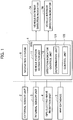
- a vehicle shown in Fig. 1 includes an electronic control unit (ECU) 1, an external sensor unit 2, an internal sensor unit 3, a global positioning system (GPS) electric-wave reception unit 4, a map database 5, a navigation system 6, a vehicle exterior direction indicator 7A, and a vehicle interior direction indicator 7B.
- ECU electronice control unit
- GPS global positioning system
- the vehicle shown in Fig. 1 is referred to as a "host vehicle” as necessary so as not to be confounded with other vehicles.
- the vehicle exterior direction indicator 7A and the vehicle interior direction indicator 7B are also collectively referred to as "direction indicators”.
- the ECU 1 corresponding to a determination unit and a control circuit in a direction indicator control device, can be implemented by a microcomputer including a central processing unit (CPU), a memory, and an input-output unit.
- a computer program for fabricating the ECU is installed on the microcomputer and is executed, so that the microcomputer functions as the ECU 1. While the embodiment is illustrated with the case in which the software is installed to fabricate the ECU 1, dedicated hardware for executing each information processing as described below can be prepared to compose the ECU 1.
- the external sensor unit 2 includes a radar unit or a camera (not shown) for acquiring surrounding information of the host vehicle so as to output the information to the ECU 1 and the navigation system 6.
- the internal sensor unit 3 includes a velocity sensor or a yaw angle sensor (not shown) for acquiring a velocity or a yaw angle of the host vehicle so as to output the velocity and the yaw angle to the ECU 1 and the navigation system 6.
- the GPS electric-wave reception unit 4 receives electric waves from three or more GPS satellites to acquire positional information indicating a position of the host vehicle, so as to output the positional information to the ECU 1 and the navigation system 6.
- the map database 5 stores map information on an area in which the host vehicle is to travel so that the ECU 1 and the navigation system 6 refer to the map information.
- the map information includes information on positions of roads and intersections. Examples of intersections include a crossroads, a T-junction, and a circular intersection referred to as a roundabout.
- roundabout refers to an intersection which is a circular road (loop road) in which three or more roads join up.
- the roundabout refers to a loop road.
- the map information includes information on a roundabout.
- the information on a roundabout includes a traveling direction of the vehicle in the roundabout (clockwise direction or counterclockwise direction), and points in the roundabout at which plural roads join up.
- the navigation system 6 is a device for guiding the host vehicle to a destination set by an occupant such as a driver.
- the navigation system 6 estimates a position of the host vehicle based on each piece of information output from the external sensor unit 2, the internal sensor unit 3, and the GPS electric-wave reception unit 4, calculates a presumed traveling route to a destination, and guides the host vehicle to the destination.
- the navigation system 6 outputs the information on the presumed traveling route to the ECU 1.
- the ECU 1 includes a vehicle position estimation unit 11 and a direction indicator control unit 12.
- the vehicle position estimation unit 11 estimates a position of the host vehicle based on each piece of information output from the external sensor unit 2, the internal sensor unit 3, and the GPS electric-wave reception unit 4.
- the direction indicator control unit 12 includes a determination unit (determination circuit) 121 for determining whether there is any roundabout along the presumed traveling route on which the host vehicle is to travel, and a control unit (control circuit) 122 for inhibiting directional indication made by the direction indicators (7A, 7B) of the host vehicle upon the entrance of the roundabout determined to be present on the presumed traveling route.
- the control unit 122 of the direction indicator control unit 12 controls the vehicle exterior direction indicator 7A and the vehicle interior direction indicator 7B in accordance with the positional information of the host vehicle acquired by the vehicle position estimation unit 11, the map information in the map database 5, and the information on the presumed traveling route generated by the navigation system 6.
- the vehicle exterior direction indicator 7A includes a right-turn signal and a left-turn signal installed in external parts of the host vehicle for indicating a right turn or a left turn of the host vehicle to other vehicles or pedestrians.
- the vehicle interior direction indicator 7B includes a right-turn signal and a left-turn signal installed in the compartment of the host vehicle for indicating the right turn or the left turn to the occupant such as the driver.
- the direction indicator control unit 12 controls the vehicle exterior direction indicator 7A and the vehicle interior direction indicator 7B so as to turn on the respective right-turn signals while the respective left-turn signals are in the OFF state. Similarly, the direction indicator control unit 12 controls the vehicle exterior direction indicator 7A and the vehicle interior direction indicator 7B so as to turn on the respective left-turn signals while the respective right-turn signals are in the OFF state. The vehicle exterior direction indicator 7A and the vehicle interior direction indicator 7B are thus operated synchronously.
- the embodiment is further described below with reference to the flowcharts.
- the following is control processing according to the embodiment in a case in which the direction indicators are presumed to be controlled so as to provide the directional indication toward a direction in which the vehicle is to travel when the vehicle is entering a point at which roads join together.
- the presumed traveling route includes an intersection at which the host vehicle is to turn to the right
- the directional indicators on the right side are automatically operated in front of the intersection.
- a first example of a direction indicator control method executed by the direction indicator control unit 12 is described below with reference to the flowcharts shown in Fig. 2 and Fig. 3 .
- the direction indicator control unit 12 executes the processing shown in Fig. 2 and Fig. 3 successively on the presumed traveling route.
- the first example is illustrated with a case in which the host vehicle is traveling in accordance with the guidance by the navigation system 6 based on the information on the presumed traveling route.
- the first example uses a directional indication execution flag f1 and a directional indication inhibition flag f2, both being switched between the ON and OFF states.
- the control unit 122 of the direction indicator control unit 12 preliminarily acquires, from the map information, locations of points on the presumed traveling route which need to be determined whether the directional indication should be made (hereinafter referred to as "directional indication determination points").
- directional indication determination points For example, a crossroads or a T-junction includes a single directional indication determination point at which the respective roads join with each other.
- a roundabout includes a plurality of directional indication determination points at which the respective roads join up into the roundabout.
- Fig. 4 illustrates a case in which roads R1 to R4 join in a roundabout RA.
- This roundabout RA includes directional indication determination points P at which the respective road R1, R2, R3, and R4 join up.
- the control unit 122 of the direction indicator control unit 12 preliminarily acquires the information on the roundabout on the presumed traveling route from the map information.
- the control unit 122 of the direction indicator control unit 12 obtains locations of an exit road, an exit road joint point, an adjacent road, and an adjacent road joint point described below, based on the information on the roundabout and the information on the presumed traveling route.
- exit road refers to a road to which the host vehicle is to exit from the roundabout
- adjacent road refers to a road adjacent to the exit road in the opposite direction of the traveling direction in the roundabout
- exit road joint point refers to a point at which the exit road joins with the roundabout
- adjacent road joint point refers to a point at which the adjacent road joins with the roundabout.
- the exit road joint point is one of the directional indication determination points which is connected with the exit road.
- adjacent road joint point is one of the directional indication determination points which is connected with the adjacent road.
- the exit road joint point and the adjacent road joint point are typically referred to as nodes which are joint points at which the respective roads (links) join together.
- the exit road joint point and the adjacent road joint point may also be obtained in accordance with the positions of the corresponding exit and adjacent roads designated by the occupant of the host vehicle.
- the direction indicator control unit 12 determines whether the host vehicle is coming close to a directional indication determination point in accordance with the position of the host vehicle estimated by the vehicle position estimation unit 11 and the position of the directional indication determination point (S1). The process ends when the host vehicle is still not close to the directional indication determination point (S1: NO).
- the determination unit 121 of the direction indicator control unit 12 determines whether the directional indication determination point belongs to a roundabout (S3). Namely, the determination unit 121 determines whether a roundabout is present along the presumed traveling route on which the host vehicle is presumed to travel. The process ends when the directional indication determination point does not belong to the roundabout (S3: NO).
- the control unit 122 of the direction indicator control unit 12 acquires the latest position of the host vehicle estimated by the vehicle position estimation unit 11 (S11), and determines whether the host vehicle has passed through the adjacent road joint point without entering the adjacent road, in accordance with the position of the host vehicle, the position of the adjacent road, and the position of the adjacent road joint point (S13). The process returns to step S11 when the host vehicle has not entered the adjacent road or has not passed through the adjacent road joint point (S13: NO).
- the control unit 122 of the direction indicator control unit 12 sets the directional indication inhibition flag f2 to be OFF (S15), and sets the directional indication execution flag f1 to be ON (S17).
- the control unit 122 of the direction indicator control unit 12 acquires the latest position of the host vehicle estimated by the vehicle position estimation unit 11 (S19), and determines whether the host vehicle has exited from the roundabout in accordance with the information on the roundabout and the position of the host vehicle (S21). Namely, the control unit 122 of the direction indicator control unit 12 determines whether the host vehicle has entered any one of the roads belonging to the roundabout or is still traveling in the roundabout (S21).
- the control unit 122 of the direction indicator control unit 12 sets the directional indication execution flag f1 to be OFF (S23) to end the process.
- the control unit 122 of the direction indicator control unit 12 determines whether the host vehicle has passed through the exit road joint point without entering the exit road in accordance with the position of the host vehicle, the position of the exit road, and the position of the exit road joint point (S25). The process returns to step S19 when the host vehicle has not entered the exit road or has not passed through the exit road joint point (S25: NO).
- the control unit 122 of the direction indicator control unit 12 sets the directional indication execution flag f1 to be OFF (S27) and the directional indication inhibition flag f2 to be ON (S29), and the process returns to step 11.
- the direction indicator control unit 12 also controls the vehicle exterior direction indicator 7A and the vehicle interior direction indicator 7B in accordance with the directional indication execution flag f1 and the directional indication inhibition flag f2, as shown in Fig. 3 , instead of the processing shown in Fig. 2 .
- control unit 122 of the direction indicator control unit 12 determines whether the directional indication inhibition flag f2 is set to ON or OFF (S31), and the process ends when set to ON (S31: ON).
- the control unit 122 of the direction indicator control unit 12 determines whether the directional indication execution flag f1 is set to ON or OFF (S33). The process proceeds to step S35 when the directional indication execution flag f1 is set to ON.
- step S35 when the vehicle exterior direction indicator 7A and the vehicle interior direction indicator 7B make no directional indication, the control unit 122 of the direction indicator control unit 12 directs the vehicle exterior direction indicator 7A and the vehicle interior direction indicator 7B to start the directional indication toward the direction to which the host vehicle is to turn when exiting from the roundabout (S35) to end the process.
- the direction to which the vehicle is to turn when exiting from the roundabout is hereinafter referred to as a "turning direction”. Namely, the turning direction is a direction in which the vehicle is to turn to enter the exit road from the roundabout.
- the turning direction is the leftward direction when the traveling direction is the clockwise direction, while the turning direction is the rightward direction when the traveling direction is the counterclockwise direction.
- the vehicle exterior direction indicator 7A and the vehicle interior direction indicator 7B turn on the left-turn signals when the traveling direction is the clockwise direction, or turn on the right-turn signal when the traveling direction is the counterclockwise direction in step S35 when not starting the directional indication yet.
- the control unit 122 of the direction indicator control unit 12 determines whether the host vehicle is coming close to the directional indication determination point (S37), in the same manner as step S1. The process ends when the host vehicle is still not close to the directional indication determination point (S37: NO).
- the control unit 122 of the direction indicator control unit 12 directs the vehicle exterior direction indicator 7A and the vehicle interior direction indicator 7B to start the rightward or leftward directional indication (S41).
- the control unit 122 of the direction indicator control unit 12 directs the respective direction indicators to start the rightward directional indication when turning to the right or start the leftward directional indication when turning to the left at the intersection, in accordance with the information on the presumed traveling route (S41).
- the vehicle exterior direction indicator 7A and the vehicle interior direction indicator 7B turn on the right-turn signals when turning to the right or turn on the left-turn signals when turning to the left at the intersection.
- the control unit 122 of the direction indicator control unit 12 acquires the latest position of the host vehicle estimated by the vehicle position estimation unit 11 (S43), and determines whether the host vehicle has passed through the directional indication determination point (S45). The process returns to step S43 when the host vehicle has not passed through the directional indication determination point yet (S45: NO).
- the control unit 122 of the direction indicator control unit 12 directs the vehicle exterior direction indicator 7A and the vehicle interior direction indicator 7B to stop the directional indication (S47) to end the process.
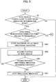
- a second example of a direction indicator control method executed by the direction indicator control unit 12 is described below with reference to the flowcharts shown in Fig. 5 and Fig. 6 .
- the direction indicator control unit 12 executes the processing shown in Fig. 5 and Fig. 6 successively on the presumed traveling route.
- the second example is also illustrated with the case in which the host vehicle is traveling in accordance with the guidance by the navigation system 6 based on the information on the presumed traveling route.
- the second embodiment does not use either the directional indication execution flag f1 or the directional indication inhibition flag f2.
- the vehicle exterior direction indicator 7A and the vehicle interior direction indicator 7B are presumed not to make any directional indication at the beginning.
- the steps with the same control processing as in the first example are indicated by the same reference numerals.
- the direction indicator control unit 12 determines whether the host vehicle is coming close to a directional indication determination point in accordance with the position of the host vehicle estimated by the vehicle position estimation unit 11 and the position of the directional indication determination point (S1). The process ends when the host vehicle is still not close to the directional indication determination point (S1: NO).
- the determination unit 121 of the direction indicator control unit 12 determines whether the directional indication determination point belongs to a roundabout (S3). Namely, the determination unit 121 determines whether a roundabout is present along the presumed traveling route on which the host vehicle is presumed to travel.
- the control unit 122 of the direction indicator control unit 12 directs the vehicle exterior direction indicator 7A and the vehicle interior direction indicator 7B to start the rightward or leftward directional indication (S41).
- the control unit 122 of the direction indicator control unit 12 acquires the latest position of the host vehicle estimated by the vehicle position estimation unit 11 (S43), and determines whether the host vehicle has passed through the directional indication determination point (S45). The process returns to step S43 when the host vehicle has not passed through the directional indication determination point yet (S45: NO).
- the control unit 122 of the direction indicator control unit 12 directs the vehicle exterior direction indicator 7A and the vehicle interior direction indicator 7B to stop the directional indication (S47) to end the process.
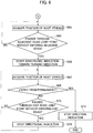
- the control unit 122 of the direction indicator control unit 12 acquires the latest position of the host vehicle estimated by the vehicle position estimation unit 11 (S61), as shown in Fig. 6 .
- the control unit 122 of the direction indicator control unit 12 determines whether the host vehicle has passed through the adjacent road joint point without entering the adjacent road, in accordance with the position of the host vehicle, the position of the adjacent road, and the position of the adjacent road joint point (S63).
- the process returns to step S61 when the host vehicle has not entered the adjacent road or has not passed through the adjacent road joint point (S63: NO).
- the control unit 122 of the direction indicator control unit 12 directs the respective direction indicators to start the directional indication toward the turning direction (S65).
- the control unit 122 of the direction indicator control unit 12 acquires the latest position of the host vehicle estimated by the vehicle position estimation unit 11 (S67), and determines whether the host vehicle has exited from the roundabout in accordance with the information on the roundabout and the position of the host vehicle (S69).
- the control unit 122 of the direction indicator control unit 12 directs the vehicle exterior direction indicator 7A and the vehicle interior direction indicator 7B to stop the directional indication (S71) to end the process.
- the control unit 122 of the direction indicator control unit 12 determines whether the host vehicle has passed through the exit road joint point without entering the exit road in accordance with the position of the host vehicle, the position of the exit road, and the position of the exit road joint point (S73). The process returns to step S67 when the host vehicle has not entered the exit road or has not passed through the exit road joint point (S73: NO).
- the control unit 122 of the direction indicator control unit 12 directs the vehicle exterior direction indicator 7A and the vehicle interior direction indicator 7B to stop the directional indication (S75), and the process returns to step S67.
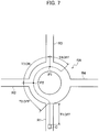
- Fig. 7 illustrates the case in which the roads R1 to R4 join in the roundabout RA.
- the traveling direction in the roundabout is presumed to be the clockwise direction.
- the road R2 is presumed to be the adjacent road, and the road R3 is presumed to be the exit road.
- Reference sign P1 refers to a point at which the exit road joins with the roundabout RA, which is the exit road joint point.
- Reference sign P2 refers to a point at which the adjacent road joins with the roundabout RA, which is the adjacent road joint point.
- the directional indication is not made in a section T1 before the host vehicle C enters the roundabout RA (T1: OFF).
- the directional indication is not made in a section T2 between the point at which the host vehicle C enters the roundabout RA and the adjacent road joint point P2 either (T2: OFF).
- the leftward directional indication is started when the host vehicle C passes through the adjacent road joint point P2 without entering the adjacent road (R2), and is stopped when the host vehicle C passes through the exit road joint point P1.
- the directional indication is made in a section T3 between the adjacent road joint point P2 and the exit road joint point P1 (T3: ON).
- the directional indication is not made when the host vehicle C does not enter the exit road (R3), namely does not exit from the roundabout RA but is still circuiting, for example, during a section T4 after passing through the exit road joint point P1 (T4: OFF).
- the directional indication is started after the host vehicle C again passes through the adjacent road joint point P2 without entering the adjacent road (R2), and is stopped when the host vehicle C again passes through the exit road joint point P1.
- the directional indication is also stopped when the host vehicle C enters the exit road (R3), namely exits from the roundabout RA, since the host vehicle C has passed through the exit road joint point P1.
- the road R1 joining with the roundabout RA is presumed to be the adjacent road
- the road R2 is presumed to be the exit road.
- Reference sign P11 refers to a point at which the exit road joins with the roundabout RA, which is the exit road joint point.
- Reference sign P12 refers to a point at which the adjacent road joins with the roundabout RA, which is the adjacent road joint point.
- the host vehicle C enters the roundabout RA through the adjacent road (R1).
- the directional indication is not made in a section T11 before the host vehicle C enters the roundabout RA (T11: OFF).
- the host vehicle C passes through the adjacent road joint point P12 once entering the roundabout RA.
- the host vehicle C is not in the adjacent road (R1) at this point.
- the leftward directional indication is thus started, and is then stopped when the host vehicle C passes through the exit road joint point P11.
- the directional indication is made in a section T12 between the adjacent road joint point P12 and the exit road joint point P11 (T12: ON).
- the directional indication is not made when the host vehicle C enters the exit road (R2), namely exits the roundabout RA, during a section T13 (T13: OFF).
- the directional indication is stopped when the host vehicle C does not enter the exit road (R2), namely, does not exit from the roundabout RA but is still circuiting, as in the case shown in Fig. 8 , since the host vehicle C has passed through the exit road joint point P11.
- the directional indication is started after the host vehicle C again passes through the adjacent road joint point P12 without entering the adjacent road (R1), and is stopped when the host vehicle C again passes through the exit road joint point P11.
- Fig. 7 and Fig. 8 illustrate the specific examples in which the host vehicle is traveling in the roundabout in the clockwise direction and the directional indication is made in the leftward direction
- the directional indication will be made in the rightward direction when the host vehicle is traveling in the roundabout in the counterclockwise direction.
- the present embodiment has exemplified the case in which the direction indicator control device is mounted on the vehicle as a target for executing the directional indication.
- the direction indicator control device may be mounted on a server capable of communicating with the target vehicle, or mounted on any other vehicle not a target vehicle, so as to communicate necessary information and instructions between the server or any other vehicle and the target vehicle so as to remotely follow the similar direction indicator control method.
- the server and the target vehicle can communicate with each other through radio communication or vehicle-to-infrastructure communication. Any other vehicle and the target vehicle can communicate with each other through vehicle-to-vehicle communication.
- the direction indicators may blink when the control circuit is ON (turned on), and may be switched off when the control circuit is OFF. For example, the control circuit may be set to be turned off or keep the OFF state when the vehicle enters a roundabout.
- the present embodiment described above determines whether there is a roundabout on a presumed traveling route, and inhibits the directional indication by the direction indicators when the vehicle enters the roundabout determined to be present.
- the present embodiment thus enables the directional indication following the rules of the roundabout for making the directional indication after entering the roundabout. Namely, the present embodiment can avoid the entrance to the roundabout while making any directional indication.
- the present embodiment also obtains the position of the adjacent road adjacent to the exit road in the opposite direction of the traveling direction and the position of the adjacent road joint point, determines whether the host vehicle has passed through the adjacent road joint point without entering the adjacent road, and directs the direction indicators to start the directional indication toward the turning direction when the host vehicle is determined to have passed through the point.
- the present embodiment thus enables the respective direction indicators to follow the rules of the roundabout to start the directional indication toward the turning direction when the host vehicle has passed through the adjacent road joint point without entering the adjacent road. Namely, the present embodiment can prevent the host vehicle from passing through the adjacent road joint point and keeping traveling in the roundabout without making any directional indication or while wrongly making the directional indication toward the direction opposite to the turning direction.
- the present embodiment also obtains the position of the exit road and the position of the exit road joint point, determines whether the host vehicle has passed through the exit road joint point without entering the exit road, and directs the direction indicators to stop the directional indication when the host vehicle is determined to have passed through the exit road joint point without entering the exit road.
- the present embodiment thus enables the respective direction indicators to follow the rules of the roundabout to stop the directional indication when the host vehicle has passed through the exit road joint point without entering the exit road. Namely, the present embodiment can prevent the host vehicle from passing through the exit road joint point and keeping traveling in the roundabout while making any directional indication.
Landscapes
- Engineering & Computer Science (AREA)
- Radar, Positioning & Navigation (AREA)
- Remote Sensing (AREA)
- Automation & Control Theory (AREA)
- Physics & Mathematics (AREA)
- General Physics & Mathematics (AREA)
- Mechanical Engineering (AREA)
- Navigation (AREA)
- Traffic Control Systems (AREA)
- Control Of Position, Course, Altitude, Or Attitude Of Moving Bodies (AREA)
Abstract
Description
- The present invention relates to a direction indicator control method and a direction indicator control device.
- Route guiding technology at a circular intersection is known that displays an arrow indicating a traveling direction toward a road to exit at each point branching into the corresponding connected road.
- Patent Document 1: Japanese Unexamined Patent Application Publication No.
2001-336944 - The above technology relates to the route guidance at the circular intersection referred to as a roundabout. The rules at a roundabout typically differ from the rules at other intersections such as a crossroads. The above technology may not be applicable to directional indication at a roundabout while following the rules of the roundabout.
- To solve the above conventional problem, the present invention provides a direction indicator control method and a direction indicator control device enabling directional indication following rules of a corresponding roundabout.
- A direction indicator control unit according to an aspect of the present invention inhibits a direction indicator of a vehicle from making a directional indication when the vehicle enters a roundabout determined to be present along a presumed traveling route on which the vehicle is presumed to travel.
- The present invention enables the directional indication following rules of a corresponding roundabout.
-
- [
Fig. 1] Fig. 1 is a functional block diagram illustrating part of a vehicle equipped with a direction indicator control device according to an embodiment of the present invention. - [
Fig. 2] Fig. 2 is the first flowchart for explaining a direction indicator control method of a first example. - [
Fig. 3] Fig. 3 is the second flowchart for explaining the direction indicator control method of the first example. - [
Fig. 4] Fig. 4 is a diagram illustrating an example of direction indication determination points at a roundabout. - [
Fig. 5] Fig. 5 is the first flowchart for explaining a direction indicator control method of a second example. - [
Fig. 6] Fig. 6 is the second flowchart for explaining the direction indicator control method of the second example. - [
Fig. 7] Fig. 7 is a diagram illustrating a first specific example of directional indication at a roundabout. - [
Fig. 8] Fig. 8 is a diagram illustrating a second specific example of directional indication at a roundabout. - An embodiment of the present invention will be described in detail below with reference to the drawings. The same elements are indicated by the same reference numerals, and overlapping explanations are not repeated below.
- A vehicle shown in
Fig. 1 includes an electronic control unit (ECU) 1, anexternal sensor unit 2, aninternal sensor unit 3, a global positioning system (GPS) electric-wave reception unit 4, amap database 5, anavigation system 6, a vehicleexterior direction indicator 7A, and a vehicleinterior direction indicator 7B. The vehicle shown inFig. 1 is referred to as a "host vehicle" as necessary so as not to be confounded with other vehicles. The vehicleexterior direction indicator 7A and the vehicleinterior direction indicator 7B are also collectively referred to as "direction indicators". - The
ECU 1, corresponding to a determination unit and a control circuit in a direction indicator control device, can be implemented by a microcomputer including a central processing unit (CPU), a memory, and an input-output unit. A computer program for fabricating the ECU is installed on the microcomputer and is executed, so that the microcomputer functions as theECU 1. While the embodiment is illustrated with the case in which the software is installed to fabricate theECU 1, dedicated hardware for executing each information processing as described below can be prepared to compose theECU 1. - The
external sensor unit 2 includes a radar unit or a camera (not shown) for acquiring surrounding information of the host vehicle so as to output the information to theECU 1 and thenavigation system 6. - The
internal sensor unit 3 includes a velocity sensor or a yaw angle sensor (not shown) for acquiring a velocity or a yaw angle of the host vehicle so as to output the velocity and the yaw angle to theECU 1 and thenavigation system 6. - The GPS electric-
wave reception unit 4 receives electric waves from three or more GPS satellites to acquire positional information indicating a position of the host vehicle, so as to output the positional information to theECU 1 and thenavigation system 6. - The
map database 5 stores map information on an area in which the host vehicle is to travel so that theECU 1 and thenavigation system 6 refer to the map information. The map information includes information on positions of roads and intersections. Examples of intersections include a crossroads, a T-junction, and a circular intersection referred to as a roundabout. - The term "roundabout" refers to an intersection which is a circular road (loop road) in which three or more roads join up. Hereinafter, the roundabout refers to a loop road. The map information includes information on a roundabout. The information on a roundabout includes a traveling direction of the vehicle in the roundabout (clockwise direction or counterclockwise direction), and points in the roundabout at which plural roads join up.
- The
navigation system 6 is a device for guiding the host vehicle to a destination set by an occupant such as a driver. Thenavigation system 6 estimates a position of the host vehicle based on each piece of information output from theexternal sensor unit 2, theinternal sensor unit 3, and the GPS electric-wave reception unit 4, calculates a presumed traveling route to a destination, and guides the host vehicle to the destination. Thenavigation system 6 outputs the information on the presumed traveling route to theECU 1. - The ECU 1 includes a vehicle
position estimation unit 11 and a directionindicator control unit 12. - The vehicle
position estimation unit 11 estimates a position of the host vehicle based on each piece of information output from theexternal sensor unit 2, theinternal sensor unit 3, and the GPS electric-wave reception unit 4. The directionindicator control unit 12 includes a determination unit (determination circuit) 121 for determining whether there is any roundabout along the presumed traveling route on which the host vehicle is to travel, and a control unit (control circuit) 122 for inhibiting directional indication made by the direction indicators (7A, 7B) of the host vehicle upon the entrance of the roundabout determined to be present on the presumed traveling route. - The
control unit 122 of the directionindicator control unit 12 controls the vehicleexterior direction indicator 7A and the vehicleinterior direction indicator 7B in accordance with the positional information of the host vehicle acquired by the vehicleposition estimation unit 11, the map information in themap database 5, and the information on the presumed traveling route generated by thenavigation system 6. - The vehicle
exterior direction indicator 7A includes a right-turn signal and a left-turn signal installed in external parts of the host vehicle for indicating a right turn or a left turn of the host vehicle to other vehicles or pedestrians. - The vehicle
interior direction indicator 7B includes a right-turn signal and a left-turn signal installed in the compartment of the host vehicle for indicating the right turn or the left turn to the occupant such as the driver. - The direction
indicator control unit 12 controls the vehicleexterior direction indicator 7A and the vehicleinterior direction indicator 7B so as to turn on the respective right-turn signals while the respective left-turn signals are in the OFF state. Similarly, the directionindicator control unit 12 controls the vehicleexterior direction indicator 7A and the vehicleinterior direction indicator 7B so as to turn on the respective left-turn signals while the respective right-turn signals are in the OFF state. The vehicleexterior direction indicator 7A and the vehicleinterior direction indicator 7B are thus operated synchronously. - The embodiment is further described below with reference to the flowcharts. The following is control processing according to the embodiment in a case in which the direction indicators are presumed to be controlled so as to provide the directional indication toward a direction in which the vehicle is to travel when the vehicle is entering a point at which roads join together. For example, when the presumed traveling route includes an intersection at which the host vehicle is to turn to the right, the directional indicators on the right side are automatically operated in front of the intersection.
- A first example of a direction indicator control method executed by the direction
indicator control unit 12 is described below with reference to the flowcharts shown inFig. 2 andFig. 3 . The directionindicator control unit 12 executes the processing shown inFig. 2 andFig. 3 successively on the presumed traveling route. The first example is illustrated with a case in which the host vehicle is traveling in accordance with the guidance by thenavigation system 6 based on the information on the presumed traveling route. The first example uses a directional indication execution flag f1 and a directional indication inhibition flag f2, both being switched between the ON and OFF states. - The
control unit 122 of the directionindicator control unit 12 preliminarily acquires, from the map information, locations of points on the presumed traveling route which need to be determined whether the directional indication should be made (hereinafter referred to as "directional indication determination points"). For example, a crossroads or a T-junction includes a single directional indication determination point at which the respective roads join with each other. A roundabout includes a plurality of directional indication determination points at which the respective roads join up into the roundabout. -
Fig. 4 illustrates a case in which roads R1 to R4 join in a roundabout RA. This roundabout RA includes directional indication determination points P at which the respective road R1, R2, R3, and R4 join up. - The
control unit 122 of the directionindicator control unit 12 preliminarily acquires the information on the roundabout on the presumed traveling route from the map information. - The
control unit 122 of the directionindicator control unit 12 obtains locations of an exit road, an exit road joint point, an adjacent road, and an adjacent road joint point described below, based on the information on the roundabout and the information on the presumed traveling route. - As used herein, the term "exit road" refers to a road to which the host vehicle is to exit from the roundabout, and the term "adjacent road" refers to a road adjacent to the exit road in the opposite direction of the traveling direction in the roundabout. The term "exit road joint point" refers to a point at which the exit road joins with the roundabout, and the term "adjacent road joint point" refers to a point at which the adjacent road joins with the roundabout. The exit road joint point is one of the directional indication determination points which is connected with the exit road. The adjacent road joint point is one of the directional indication determination points which is connected with the adjacent road.
- The exit road joint point and the adjacent road joint point are typically referred to as nodes which are joint points at which the respective roads (links) join together.
- The exit road joint point and the adjacent road joint point may also be obtained in accordance with the positions of the corresponding exit and adjacent roads designated by the occupant of the host vehicle.
- As shown in
Fig. 2 , first, the directionindicator control unit 12 determines whether the host vehicle is coming close to a directional indication determination point in accordance with the position of the host vehicle estimated by the vehicleposition estimation unit 11 and the position of the directional indication determination point (S1). The process ends when the host vehicle is still not close to the directional indication determination point (S1: NO). - When the host vehicle is coming close to the directional indication determination point (S1: YES), the
determination unit 121 of the directionindicator control unit 12 determines whether the directional indication determination point belongs to a roundabout (S3). Namely, thedetermination unit 121 determines whether a roundabout is present along the presumed traveling route on which the host vehicle is presumed to travel. The process ends when the directional indication determination point does not belong to the roundabout (S3: NO). - When the directional indication determination point belongs to the roundabout (S3: YES), the
control unit 122 of the directionindicator control unit 12 acquires the latest position of the host vehicle estimated by the vehicle position estimation unit 11 (S11), and determines whether the host vehicle has passed through the adjacent road joint point without entering the adjacent road, in accordance with the position of the host vehicle, the position of the adjacent road, and the position of the adjacent road joint point (S13). The process returns to step S11 when the host vehicle has not entered the adjacent road or has not passed through the adjacent road joint point (S13: NO). - When the host vehicle has passed through the adjacent road joint point without entering the adjacent road (S13: YES), the
control unit 122 of the directionindicator control unit 12 sets the directional indication inhibition flag f2 to be OFF (S15), and sets the directional indication execution flag f1 to be ON (S17). - The
control unit 122 of the directionindicator control unit 12 then acquires the latest position of the host vehicle estimated by the vehicle position estimation unit 11 (S19), and determines whether the host vehicle has exited from the roundabout in accordance with the information on the roundabout and the position of the host vehicle (S21). Namely, thecontrol unit 122 of the directionindicator control unit 12 determines whether the host vehicle has entered any one of the roads belonging to the roundabout or is still traveling in the roundabout (S21). - When the host vehicle has entered any one of the roads (S21: YES), the
control unit 122 of the directionindicator control unit 12 sets the directional indication execution flag f1 to be OFF (S23) to end the process. - When the host vehicle has not exited from the roundabout yet (S21: NO), the
control unit 122 of the directionindicator control unit 12 determines whether the host vehicle has passed through the exit road joint point without entering the exit road in accordance with the position of the host vehicle, the position of the exit road, and the position of the exit road joint point (S25). The process returns to step S19 when the host vehicle has not entered the exit road or has not passed through the exit road joint point (S25: NO). - When the host vehicle has passed through the exit road joint point without entering the exit road (S25: YES), the
control unit 122 of the directionindicator control unit 12 sets the directional indication execution flag f1 to be OFF (S27) and the directional indication inhibition flag f2 to be ON (S29), and the process returns to step 11. - The direction
indicator control unit 12 also controls the vehicleexterior direction indicator 7A and the vehicleinterior direction indicator 7B in accordance with the directional indication execution flag f1 and the directional indication inhibition flag f2, as shown inFig. 3 , instead of the processing shown inFig. 2 . - As shown in
Fig. 3 , thecontrol unit 122 of the directionindicator control unit 12 determines whether the directional indication inhibition flag f2 is set to ON or OFF (S31), and the process ends when set to ON (S31: ON). - When the directional indication inhibition flag f2 is set to OFF (S31: OFF), the
control unit 122 of the directionindicator control unit 12 determines whether the directional indication execution flag f1 is set to ON or OFF (S33). The process proceeds to step S35 when the directional indication execution flag f1 is set to ON. - In step S35, when the vehicle
exterior direction indicator 7A and the vehicleinterior direction indicator 7B make no directional indication, thecontrol unit 122 of the directionindicator control unit 12 directs the vehicleexterior direction indicator 7A and the vehicleinterior direction indicator 7B to start the directional indication toward the direction to which the host vehicle is to turn when exiting from the roundabout (S35) to end the process. - The direction to which the vehicle is to turn when exiting from the roundabout is hereinafter referred to as a "turning direction". Namely, the turning direction is a direction in which the vehicle is to turn to enter the exit road from the roundabout.
- The turning direction is the leftward direction when the traveling direction is the clockwise direction, while the turning direction is the rightward direction when the traveling direction is the counterclockwise direction. The vehicle
exterior direction indicator 7A and the vehicleinterior direction indicator 7B turn on the left-turn signals when the traveling direction is the clockwise direction, or turn on the right-turn signal when the traveling direction is the counterclockwise direction in step S35 when not starting the directional indication yet. - When the directional indication execution flag f1 is set to OFF (S33: OFF), the
control unit 122 of the directionindicator control unit 12 determines whether the host vehicle is coming close to the directional indication determination point (S37), in the same manner as step S1. The process ends when the host vehicle is still not close to the directional indication determination point (S37: NO). - When the host vehicle is coming close to the directional indication determination point (S37: YES), the
control unit 122 of the directionindicator control unit 12 directs the vehicleexterior direction indicator 7A and the vehicleinterior direction indicator 7B to start the rightward or leftward directional indication (S41). In particular, thecontrol unit 122 of the directionindicator control unit 12 directs the respective direction indicators to start the rightward directional indication when turning to the right or start the leftward directional indication when turning to the left at the intersection, in accordance with the information on the presumed traveling route (S41). The vehicleexterior direction indicator 7A and the vehicleinterior direction indicator 7B turn on the right-turn signals when turning to the right or turn on the left-turn signals when turning to the left at the intersection. - The
control unit 122 of the directionindicator control unit 12 then acquires the latest position of the host vehicle estimated by the vehicle position estimation unit 11 (S43), and determines whether the host vehicle has passed through the directional indication determination point (S45). The process returns to step S43 when the host vehicle has not passed through the directional indication determination point yet (S45: NO). - When the host vehicle has passed through the directional indication determination point (S45: YES), the
control unit 122 of the directionindicator control unit 12 directs the vehicleexterior direction indicator 7A and the vehicleinterior direction indicator 7B to stop the directional indication (S47) to end the process. - A second example of a direction indicator control method executed by the direction
indicator control unit 12 is described below with reference to the flowcharts shown inFig. 5 andFig. 6 . The directionindicator control unit 12 executes the processing shown inFig. 5 andFig. 6 successively on the presumed traveling route. The second example is also illustrated with the case in which the host vehicle is traveling in accordance with the guidance by thenavigation system 6 based on the information on the presumed traveling route. The second embodiment, however, does not use either the directional indication execution flag f1 or the directional indication inhibition flag f2. The vehicleexterior direction indicator 7A and the vehicleinterior direction indicator 7B are presumed not to make any directional indication at the beginning. The steps with the same control processing as in the first example are indicated by the same reference numerals. - As shown in
Fig. 5 , first, the directionindicator control unit 12 determines whether the host vehicle is coming close to a directional indication determination point in accordance with the position of the host vehicle estimated by the vehicleposition estimation unit 11 and the position of the directional indication determination point (S1). The process ends when the host vehicle is still not close to the directional indication determination point (S1: NO). - When the host vehicle is coming close to the directional indication determination point (S1: YES), the
determination unit 121 of the directionindicator control unit 12 determines whether the directional indication determination point belongs to a roundabout (S3). Namely, thedetermination unit 121 determines whether a roundabout is present along the presumed traveling route on which the host vehicle is presumed to travel. - When the directional indication determination point does not belong to the roundabout (S3: NO), the
control unit 122 of the directionindicator control unit 12 directs the vehicleexterior direction indicator 7A and the vehicleinterior direction indicator 7B to start the rightward or leftward directional indication (S41). - The
control unit 122 of the directionindicator control unit 12 then acquires the latest position of the host vehicle estimated by the vehicle position estimation unit 11 (S43), and determines whether the host vehicle has passed through the directional indication determination point (S45). The process returns to step S43 when the host vehicle has not passed through the directional indication determination point yet (S45: NO). - When the host vehicle has passed through the directional indication determination point (S45: YES), the
control unit 122 of the directionindicator control unit 12 directs the vehicleexterior direction indicator 7A and the vehicleinterior direction indicator 7B to stop the directional indication (S47) to end the process. - When the directional indication determination point belongs to the roundabout (S3: YES), the
control unit 122 of the directionindicator control unit 12 acquires the latest position of the host vehicle estimated by the vehicle position estimation unit 11 (S61), as shown inFig. 6 . Thecontrol unit 122 of the directionindicator control unit 12 then determines whether the host vehicle has passed through the adjacent road joint point without entering the adjacent road, in accordance with the position of the host vehicle, the position of the adjacent road, and the position of the adjacent road joint point (S63). The process returns to step S61 when the host vehicle has not entered the adjacent road or has not passed through the adjacent road joint point (S63: NO). - When the host vehicle has passed through the adjacent road joint point without entering the adjacent road (S63: YES), the
control unit 122 of the directionindicator control unit 12 directs the respective direction indicators to start the directional indication toward the turning direction (S65). - The
control unit 122 of the directionindicator control unit 12 then acquires the latest position of the host vehicle estimated by the vehicle position estimation unit 11 (S67), and determines whether the host vehicle has exited from the roundabout in accordance with the information on the roundabout and the position of the host vehicle (S69). - When the host vehicle has exited from the roundabout (S69: YES), the
control unit 122 of the directionindicator control unit 12 directs the vehicleexterior direction indicator 7A and the vehicleinterior direction indicator 7B to stop the directional indication (S71) to end the process. - When the host vehicle has not exited from the roundabout yet (S69: NO), the
control unit 122 of the directionindicator control unit 12 determines whether the host vehicle has passed through the exit road joint point without entering the exit road in accordance with the position of the host vehicle, the position of the exit road, and the position of the exit road joint point (S73). The process returns to step S67 when the host vehicle has not entered the exit road or has not passed through the exit road joint point (S73: NO). - When the host vehicle has passed through the exit road joint point without entering the exit road (S73: YES), the
control unit 122 of the directionindicator control unit 12 directs the vehicleexterior direction indicator 7A and the vehicleinterior direction indicator 7B to stop the directional indication (S75), and the process returns to step S67. - Specific examples of the directional indication in a roundabout are described below with reference to
Fig. 7 andFig. 8 . -
Fig. 7 illustrates the case in which the roads R1 to R4 join in the roundabout RA. The traveling direction in the roundabout is presumed to be the clockwise direction. The road R2 is presumed to be the adjacent road, and the road R3 is presumed to be the exit road. Reference sign P1 refers to a point at which the exit road joins with the roundabout RA, which is the exit road joint point. Reference sign P2 refers to a point at which the adjacent road joins with the roundabout RA, which is the adjacent road joint point. - The directional indication is not made in a section T1 before the host vehicle C enters the roundabout RA (T1: OFF). The directional indication is not made in a section T2 between the point at which the host vehicle C enters the roundabout RA and the adjacent road joint point P2 either (T2: OFF).
- The leftward directional indication is started when the host vehicle C passes through the adjacent road joint point P2 without entering the adjacent road (R2), and is stopped when the host vehicle C passes through the exit road joint point P1. Namely, the directional indication is made in a section T3 between the adjacent road joint point P2 and the exit road joint point P1 (T3: ON).
- The directional indication is not made when the host vehicle C does not enter the exit road (R3), namely does not exit from the roundabout RA but is still circuiting, for example, during a section T4 after passing through the exit road joint point P1 (T4: OFF).
- Although not shown, the directional indication is started after the host vehicle C again passes through the adjacent road joint point P2 without entering the adjacent road (R2), and is stopped when the host vehicle C again passes through the exit road joint point P1.
- The directional indication is also stopped when the host vehicle C enters the exit road (R3), namely exits from the roundabout RA, since the host vehicle C has passed through the exit road joint point P1.
- As shown in
Fig. 8 , the road R1 joining with the roundabout RA is presumed to be the adjacent road, and the road R2 is presumed to be the exit road. Reference sign P11 refers to a point at which the exit road joins with the roundabout RA, which is the exit road joint point. Reference sign P12 refers to a point at which the adjacent road joins with the roundabout RA, which is the adjacent road joint point. - Differing from the case shown in
Fig. 7 , the host vehicle C enters the roundabout RA through the adjacent road (R1). The directional indication is not made in a section T11 before the host vehicle C enters the roundabout RA (T11: OFF). - The host vehicle C passes through the adjacent road joint point P12 once entering the roundabout RA. The host vehicle C is not in the adjacent road (R1) at this point. The leftward directional indication is thus started, and is then stopped when the host vehicle C passes through the exit road joint point P11. Namely, the directional indication is made in a section T12 between the adjacent road joint point P12 and the exit road joint point P11 (T12: ON).
- The directional indication is not made when the host vehicle C enters the exit road (R2), namely exits the roundabout RA, during a section T13 (T13: OFF).
- The directional indication is stopped when the host vehicle C does not enter the exit road (R2), namely, does not exit from the roundabout RA but is still circuiting, as in the case shown in
Fig. 8 , since the host vehicle C has passed through the exit road joint point P11. The directional indication is started after the host vehicle C again passes through the adjacent road joint point P12 without entering the adjacent road (R1), and is stopped when the host vehicle C again passes through the exit road joint point P11. - While
Fig. 7 andFig. 8 illustrate the specific examples in which the host vehicle is traveling in the roundabout in the clockwise direction and the directional indication is made in the leftward direction, the directional indication will be made in the rightward direction when the host vehicle is traveling in the roundabout in the counterclockwise direction. - The present embodiment has exemplified the case in which the direction indicator control device is mounted on the vehicle as a target for executing the directional indication. Alternatively, the direction indicator control device may be mounted on a server capable of communicating with the target vehicle, or mounted on any other vehicle not a target vehicle, so as to communicate necessary information and instructions between the server or any other vehicle and the target vehicle so as to remotely follow the similar direction indicator control method. The server and the target vehicle can communicate with each other through radio communication or vehicle-to-infrastructure communication. Any other vehicle and the target vehicle can communicate with each other through vehicle-to-vehicle communication. The direction indicators may blink when the control circuit is ON (turned on), and may be switched off when the control circuit is OFF. For example, the control circuit may be set to be turned off or keep the OFF state when the vehicle enters a roundabout.
- The present embodiment described above determines whether there is a roundabout on a presumed traveling route, and inhibits the directional indication by the direction indicators when the vehicle enters the roundabout determined to be present. The present embodiment thus enables the directional indication following the rules of the roundabout for making the directional indication after entering the roundabout. Namely, the present embodiment can avoid the entrance to the roundabout while making any directional indication.
- The present embodiment also obtains the position of the adjacent road adjacent to the exit road in the opposite direction of the traveling direction and the position of the adjacent road joint point, determines whether the host vehicle has passed through the adjacent road joint point without entering the adjacent road, and directs the direction indicators to start the directional indication toward the turning direction when the host vehicle is determined to have passed through the point. The present embodiment thus enables the respective direction indicators to follow the rules of the roundabout to start the directional indication toward the turning direction when the host vehicle has passed through the adjacent road joint point without entering the adjacent road. Namely, the present embodiment can prevent the host vehicle from passing through the adjacent road joint point and keeping traveling in the roundabout without making any directional indication or while wrongly making the directional indication toward the direction opposite to the turning direction.
- The present embodiment also obtains the position of the exit road and the position of the exit road joint point, determines whether the host vehicle has passed through the exit road joint point without entering the exit road, and directs the direction indicators to stop the directional indication when the host vehicle is determined to have passed through the exit road joint point without entering the exit road. The present embodiment thus enables the respective direction indicators to follow the rules of the roundabout to stop the directional indication when the host vehicle has passed through the exit road joint point without entering the exit road. Namely, the present embodiment can prevent the host vehicle from passing through the exit road joint point and keeping traveling in the roundabout while making any directional indication.
- While the embodiment of the present invention has been described above, it should be understood that the present invention is not intended to be limited to the descriptions and the drawings composing part of this disclosure. Various alternative embodiments, examples, and technical applications will be apparent to those skilled in the art according to this disclosure.
-
- 1 ECU
- 2 EXTERNAL SENSOR UNIT
- 3 INTERNAL SENSOR UNIT
- 4 GPS ELECTRIC-WAVE RECEPTION UNIT
- 5 MAP DATABASE
- 6 NAVIGATION SYSTEM
- 7A VEHICLE EXTERIOR DIRECTION INDICATOR (DIRECTION INDICATOR)
- 7B VEHICLE INTERIOR DIRECTION INDICATOR (DIRECTION INDICATOR)
- 11 VEHICLE POSITION ESTIMATION UNIT
- 12 DIRECTION INDICATOR CONTROL UNIT
- 121 DETERMINATION UNIT
- 122 CONTROL UNIT
- C HOST VEHICLE
- f1 DIRECTIONAL INDICATION EXECUTION FLAG
- f2 DIRECTIONAL INDICATION INHIBITION FLAG
- RA ROUNDABOUT
- R1 to R5 ROAD
- P1, P11 EXIT ROAD JOINT POINT
- P2, P12 ADJACENT ROAD JOINT POINT
Claims (4)
- A direction indicator control method comprising:determining whether a roundabout is present along a presumed traveling route on which a vehicle is presumed to travel; andinhibiting a direction indicator of the vehicle from making a directional indication when the vehicle enters the roundabout when the roundabout is determined to be present on the presumed traveling route.
- The direction indicator control method according to claim 1, further comprising:obtaining a position of an adjacent road adjacent to, in an opposite direction of a traveling direction in the roundabout, an exit road through which the vehicle exits from the roundabout, and a position of an adjacent road joint point at which the adjacent road joins with the roundabout, and determining whether the vehicle has passed through the adjacent road joint point without entering the adjacent road; anddirecting the direction indicator to start the directional indication toward a direction in which the vehicle turns to exit from the roundabout when the vehicle is determined to have passed through the adjacent road joint point without entering the adjacent road.
- The direction indicator control method according to claim 2, further comprising:obtaining a position of the exit road and a position of an exit road joint point at which the exit road joins with the roundabout, and determining whether the host vehicle has passed through the exit road joint point without entering the exit road; anddirecting the direction indicator to stop the directional indication when the host vehicle is determined to have passed through the exit road joint point without entering the exit road.
- A direction indicator control device comprising:a direction indicator installed in a vehicle;a determination unit configured to determine whether a roundabout is present along a presumed traveling route on which the vehicle is presumed to travel; anda control circuit configured to inhibit the direction indicator of the vehicle from making a directional indication when the vehicle enters the roundabout when the roundabout is determined to be present on the presumed traveling route.
Applications Claiming Priority (1)
| Application Number | Priority Date | Filing Date | Title |
|---|---|---|---|
| PCT/JP2017/023417 WO2019003277A1 (en) | 2017-06-26 | 2017-06-26 | Direction indictor control method and direction indicator control device |
Publications (3)
| Publication Number | Publication Date |
|---|---|
| EP3647732A1 true EP3647732A1 (en) | 2020-05-06 |
| EP3647732A4 EP3647732A4 (en) | 2020-10-07 |
| EP3647732B1 EP3647732B1 (en) | 2024-02-28 |
Family
ID=64741193
Family Applications (1)
| Application Number | Title | Priority Date | Filing Date |
|---|---|---|---|
| EP17915527.0A Active EP3647732B1 (en) | 2017-06-26 | 2017-06-26 | Direction indicator control method and direction indicator control device |
Country Status (10)
| Country | Link |
|---|---|
| US (1) | US11332068B2 (en) |
| EP (1) | EP3647732B1 (en) |
| JP (1) | JP6870735B2 (en) |
| KR (1) | KR20200010392A (en) |
| CN (1) | CN110799805A (en) |
| BR (1) | BR112019027778A2 (en) |
| CA (1) | CA3068178A1 (en) |
| MX (1) | MX2019015107A (en) |
| RU (1) | RU2743317C1 (en) |
| WO (1) | WO2019003277A1 (en) |
Cited By (2)
| Publication number | Priority date | Publication date | Assignee | Title |
|---|---|---|---|---|
| CN112124191A (en) * | 2020-09-22 | 2020-12-25 | 北京京东乾石科技有限公司 | Unmanned vehicle turn signal control method, device, unmanned vehicle and storage medium |
| EP4206036A4 (en) * | 2020-08-25 | 2023-10-25 | Nissan Motor Co., Ltd. | Vehicle control method and vehicle control device |
Families Citing this family (4)
| Publication number | Priority date | Publication date | Assignee | Title |
|---|---|---|---|---|
| JP2021039007A (en) * | 2019-09-03 | 2021-03-11 | 株式会社デンソー | Display control device, display control method, and display control program |
| CN112732859B (en) * | 2021-01-25 | 2022-05-06 | 腾讯科技(深圳)有限公司 | Prompt information generation method and device, electronic equipment and storage medium |
| CN115235494B (en) * | 2022-07-19 | 2024-08-23 | 南京四维智联科技有限公司 | Method, device, equipment and storage medium for guiding roundabout road section |
| EP4559752A1 (en) | 2023-11-24 | 2025-05-28 | Volvo Truck Corporation | Automatic turn signal cancellation in a vehicle for a roundabout |
Family Cites Families (21)
| Publication number | Priority date | Publication date | Assignee | Title |
|---|---|---|---|---|
| JPH10129342A (en) * | 1996-11-01 | 1998-05-19 | Harness Sogo Gijutsu Kenkyusho:Kk | Vehicle turn signal |
| JP3898872B2 (en) | 2000-05-26 | 2007-03-28 | アルパイン株式会社 | Navigation device |
| CN1328314A (en) * | 2000-06-13 | 2001-12-26 | 同济大学 | Method for increasing traffic throughput at cross of city ring roads |
| JP2003269979A (en) * | 2002-03-19 | 2003-09-25 | Pioneer Electronic Corp | Route guide device and route guide method |
| US20050187710A1 (en) * | 2004-02-20 | 2005-08-25 | Walker James A. | Vehicle navigation system turn indicator |
| EP1580529A1 (en) * | 2004-03-22 | 2005-09-28 | Harman/Becker Automotive Systems GmbH | System for controlling the direction indicator of a vehicle and method therefor |
| JP2006138798A (en) * | 2004-11-15 | 2006-06-01 | Nissan Motor Co Ltd | On-vehicle navigation device and route guidance method |
| JP4548154B2 (en) * | 2005-03-07 | 2010-09-22 | アイシン・エィ・ダブリュ株式会社 | Driving support device and driving support method |
| US7539574B2 (en) * | 2005-03-22 | 2009-05-26 | Denso Corporation | Vehicular navigation system |
| JP4651511B2 (en) * | 2005-11-16 | 2011-03-16 | アルパイン株式会社 | Navigation device and vehicle position determination method |
| JP4948944B2 (en) * | 2006-09-06 | 2012-06-06 | アルパイン株式会社 | Navigation device and method for drawing intersection guide map |
| JP4656439B2 (en) * | 2007-02-07 | 2011-03-23 | 株式会社デンソー | WINKER CONTROL DEVICE FOR VEHICLE |
| FR2913930B1 (en) * | 2007-03-20 | 2009-05-29 | Jean-Pierre Cado | "SYSTEM AND METHOD FOR OPERATING A DIRECTION CHANGE INDICATOR" |
| JP5051046B2 (en) * | 2008-07-31 | 2012-10-17 | アイシン・エィ・ダブリュ株式会社 | Road information guidance device, road information guidance method, and computer program |
| CN102313556B (en) * | 2010-07-01 | 2014-04-02 | 北京四维图新科技股份有限公司 | Method and device for matching paths on round island |
| JP2012149957A (en) * | 2011-01-18 | 2012-08-09 | Clarion Co Ltd | On-vehicle map display device |
| JP2015017949A (en) * | 2013-07-12 | 2015-01-29 | アイシン・エィ・ダブリュ株式会社 | Drive support system, method and program |
| US9528838B2 (en) * | 2014-12-09 | 2016-12-27 | Toyota Motor Engineering & Manufacturing North America, Inc. | Autonomous vehicle detection of and response to intersection priority |
| JP6309467B2 (en) * | 2015-01-29 | 2018-04-11 | 株式会社トヨタマップマスター | NAVIGATION DEVICE, NAVIGATION METHOD, COMPUTER PROGRAM, AND RECORDING MEDIUM CONTAINING THE COMPUTER PROGRAM |
| WO2019003278A1 (en) * | 2017-06-26 | 2019-01-03 | 日産自動車株式会社 | Method for controlling direction indicator and device for controlling direction indicator |
| JP2020083106A (en) * | 2018-11-27 | 2020-06-04 | 本田技研工業株式会社 | Vehicle control device, vehicle control method and program |
-
2017
- 2017-06-26 KR KR1020197037542A patent/KR20200010392A/en not_active Ceased
- 2017-06-26 BR BR112019027778-1A patent/BR112019027778A2/en not_active IP Right Cessation
- 2017-06-26 EP EP17915527.0A patent/EP3647732B1/en active Active
- 2017-06-26 RU RU2020102857A patent/RU2743317C1/en active
- 2017-06-26 US US16/624,641 patent/US11332068B2/en active Active
- 2017-06-26 JP JP2019526412A patent/JP6870735B2/en active Active
- 2017-06-26 CA CA3068178A patent/CA3068178A1/en not_active Abandoned
- 2017-06-26 WO PCT/JP2017/023417 patent/WO2019003277A1/en not_active Ceased
- 2017-06-26 CN CN201780092550.2A patent/CN110799805A/en active Pending
- 2017-06-26 MX MX2019015107A patent/MX2019015107A/en unknown
Cited By (3)
| Publication number | Priority date | Publication date | Assignee | Title |
|---|---|---|---|---|
| EP4206036A4 (en) * | 2020-08-25 | 2023-10-25 | Nissan Motor Co., Ltd. | Vehicle control method and vehicle control device |
| CN112124191A (en) * | 2020-09-22 | 2020-12-25 | 北京京东乾石科技有限公司 | Unmanned vehicle turn signal control method, device, unmanned vehicle and storage medium |
| CN112124191B (en) * | 2020-09-22 | 2021-11-02 | 北京京东乾石科技有限公司 | Unmanned vehicle turn signal control method, device, unmanned vehicle and storage medium |
Also Published As
| Publication number | Publication date |
|---|---|
| EP3647732B1 (en) | 2024-02-28 |
| RU2743317C1 (en) | 2021-02-17 |
| CA3068178A1 (en) | 2019-01-03 |
| MX2019015107A (en) | 2020-02-05 |
| KR20200010392A (en) | 2020-01-30 |
| BR112019027778A2 (en) | 2020-07-07 |
| JP6870735B2 (en) | 2021-05-12 |
| EP3647732A4 (en) | 2020-10-07 |
| WO2019003277A1 (en) | 2019-01-03 |
| CN110799805A (en) | 2020-02-14 |
| JPWO2019003277A1 (en) | 2020-06-25 |
| US20200122632A1 (en) | 2020-04-23 |
| US11332068B2 (en) | 2022-05-17 |
Similar Documents
| Publication | Publication Date | Title |
|---|---|---|
| EP3647732A1 (en) | Direction indictor control method and direction indicator control device | |
| US11414100B2 (en) | Travel assistance method and travel assistance device | |
| US10169997B2 (en) | Vehicle alert apparatus | |
| EP3660455A1 (en) | Travel assistance method and travel assistance device | |
| CN115123213B (en) | Driving support device, vehicle, and driving support method | |
| JP6844707B2 (en) | Driving support method and driving support device | |
| WO2017104209A1 (en) | Driving assistance device | |
| US11493356B2 (en) | Direction indicator control method and direction indicator control device | |
| US20200386571A1 (en) | Vehicle control system and vehicle control program | |
| JPWO2019003992A1 (en) | Information management device | |
| US20180025642A1 (en) | Encounter vehicle determination apparatus | |
| US20240025411A1 (en) | On-board device and server for controlling driving of vehicle within intersection | |
| US20210185497A1 (en) | Control device and vehicle | |
| JP2006242643A (en) | Navigation device | |
| JP5692118B2 (en) | Vehicle communication device and intersection approach path determination system |
Legal Events
| Date | Code | Title | Description |
|---|---|---|---|
| STAA | Information on the status of an ep patent application or granted ep patent |
Free format text: STATUS: THE INTERNATIONAL PUBLICATION HAS BEEN MADE |
|
| PUAI | Public reference made under article 153(3) epc to a published international application that has entered the european phase |
Free format text: ORIGINAL CODE: 0009012 |
|
| STAA | Information on the status of an ep patent application or granted ep patent |
Free format text: STATUS: REQUEST FOR EXAMINATION WAS MADE |
|
| 17P | Request for examination filed |
Effective date: 20200123 |
|
| AK | Designated contracting states |
Kind code of ref document: A1 Designated state(s): AL AT BE BG CH CY CZ DE DK EE ES FI FR GB GR HR HU IE IS IT LI LT LU LV MC MK MT NL NO PL PT RO RS SE SI SK SM TR |
|
| AX | Request for extension of the european patent |
Extension state: BA ME |
|
| DAV | Request for validation of the european patent (deleted) | ||
| DAX | Request for extension of the european patent (deleted) | ||
| A4 | Supplementary search report drawn up and despatched |
Effective date: 20200909 |
|
| RIC1 | Information provided on ipc code assigned before grant |
Ipc: B60Q 1/34 20060101ALI20200903BHEP Ipc: G01C 21/36 20060101AFI20200903BHEP Ipc: B60Q 1/40 20060101ALI20200903BHEP |
|
| STAA | Information on the status of an ep patent application or granted ep patent |
Free format text: STATUS: EXAMINATION IS IN PROGRESS |
|
| 17Q | First examination report despatched |
Effective date: 20210824 |
|
| GRAP | Despatch of communication of intention to grant a patent |
Free format text: ORIGINAL CODE: EPIDOSNIGR1 |
|
| STAA | Information on the status of an ep patent application or granted ep patent |
Free format text: STATUS: GRANT OF PATENT IS INTENDED |
|
| INTG | Intention to grant announced |
Effective date: 20231012 |
|
| GRAS | Grant fee paid |
Free format text: ORIGINAL CODE: EPIDOSNIGR3 |
|
| GRAA | (expected) grant |
Free format text: ORIGINAL CODE: 0009210 |
|
| STAA | Information on the status of an ep patent application or granted ep patent |
Free format text: STATUS: THE PATENT HAS BEEN GRANTED |
|
| AK | Designated contracting states |
Kind code of ref document: B1 Designated state(s): AL AT BE BG CH CY CZ DE DK EE ES FI FR GB GR HR HU IE IS IT LI LT LU LV MC MK MT NL NO PL PT RO RS SE SI SK SM TR |
|
| REG | Reference to a national code |
Ref country code: GB Ref legal event code: FG4D |
|
| REG | Reference to a national code |
Ref country code: CH Ref legal event code: EP |
|
| REG | Reference to a national code |
Ref country code: DE Ref legal event code: R096 Ref document number: 602017079658 Country of ref document: DE |
|
| REG | Reference to a national code |
Ref country code: IE Ref legal event code: FG4D |
|
| REG | Reference to a national code |
Ref country code: LT Ref legal event code: MG9D |
|
| PG25 | Lapsed in a contracting state [announced via postgrant information from national office to epo] |
Ref country code: IS Free format text: LAPSE BECAUSE OF FAILURE TO SUBMIT A TRANSLATION OF THE DESCRIPTION OR TO PAY THE FEE WITHIN THE PRESCRIBED TIME-LIMIT Effective date: 20240628 |
|
| REG | Reference to a national code |
Ref country code: NL Ref legal event code: MP Effective date: 20240228 |
|
| PG25 | Lapsed in a contracting state [announced via postgrant information from national office to epo] |
Ref country code: LT Free format text: LAPSE BECAUSE OF FAILURE TO SUBMIT A TRANSLATION OF THE DESCRIPTION OR TO PAY THE FEE WITHIN THE PRESCRIBED TIME-LIMIT Effective date: 20240228 |
|
| PG25 | Lapsed in a contracting state [announced via postgrant information from national office to epo] |
Ref country code: GR Free format text: LAPSE BECAUSE OF FAILURE TO SUBMIT A TRANSLATION OF THE DESCRIPTION OR TO PAY THE FEE WITHIN THE PRESCRIBED TIME-LIMIT Effective date: 20240529 |
|
| PG25 | Lapsed in a contracting state [announced via postgrant information from national office to epo] |
Ref country code: RS Free format text: LAPSE BECAUSE OF FAILURE TO SUBMIT A TRANSLATION OF THE DESCRIPTION OR TO PAY THE FEE WITHIN THE PRESCRIBED TIME-LIMIT Effective date: 20240528 Ref country code: HR Free format text: LAPSE BECAUSE OF FAILURE TO SUBMIT A TRANSLATION OF THE DESCRIPTION OR TO PAY THE FEE WITHIN THE PRESCRIBED TIME-LIMIT Effective date: 20240228 Ref country code: NL Free format text: LAPSE BECAUSE OF FAILURE TO SUBMIT A TRANSLATION OF THE DESCRIPTION OR TO PAY THE FEE WITHIN THE PRESCRIBED TIME-LIMIT Effective date: 20240228 |
|
| PG25 | Lapsed in a contracting state [announced via postgrant information from national office to epo] |
Ref country code: ES Free format text: LAPSE BECAUSE OF FAILURE TO SUBMIT A TRANSLATION OF THE DESCRIPTION OR TO PAY THE FEE WITHIN THE PRESCRIBED TIME-LIMIT Effective date: 20240228 |
|
| PG25 | Lapsed in a contracting state [announced via postgrant information from national office to epo] |
Ref country code: RS Free format text: LAPSE BECAUSE OF FAILURE TO SUBMIT A TRANSLATION OF THE DESCRIPTION OR TO PAY THE FEE WITHIN THE PRESCRIBED TIME-LIMIT Effective date: 20240528 Ref country code: NO Free format text: LAPSE BECAUSE OF FAILURE TO SUBMIT A TRANSLATION OF THE DESCRIPTION OR TO PAY THE FEE WITHIN THE PRESCRIBED TIME-LIMIT Effective date: 20240528 Ref country code: NL Free format text: LAPSE BECAUSE OF FAILURE TO SUBMIT A TRANSLATION OF THE DESCRIPTION OR TO PAY THE FEE WITHIN THE PRESCRIBED TIME-LIMIT Effective date: 20240228 Ref country code: LT Free format text: LAPSE BECAUSE OF FAILURE TO SUBMIT A TRANSLATION OF THE DESCRIPTION OR TO PAY THE FEE WITHIN THE PRESCRIBED TIME-LIMIT Effective date: 20240228 Ref country code: IS Free format text: LAPSE BECAUSE OF FAILURE TO SUBMIT A TRANSLATION OF THE DESCRIPTION OR TO PAY THE FEE WITHIN THE PRESCRIBED TIME-LIMIT Effective date: 20240628 Ref country code: HR Free format text: LAPSE BECAUSE OF FAILURE TO SUBMIT A TRANSLATION OF THE DESCRIPTION OR TO PAY THE FEE WITHIN THE PRESCRIBED TIME-LIMIT Effective date: 20240228 Ref country code: GR Free format text: LAPSE BECAUSE OF FAILURE TO SUBMIT A TRANSLATION OF THE DESCRIPTION OR TO PAY THE FEE WITHIN THE PRESCRIBED TIME-LIMIT Effective date: 20240529 Ref country code: FI Free format text: LAPSE BECAUSE OF FAILURE TO SUBMIT A TRANSLATION OF THE DESCRIPTION OR TO PAY THE FEE WITHIN THE PRESCRIBED TIME-LIMIT Effective date: 20240228 Ref country code: ES Free format text: LAPSE BECAUSE OF FAILURE TO SUBMIT A TRANSLATION OF THE DESCRIPTION OR TO PAY THE FEE WITHIN THE PRESCRIBED TIME-LIMIT Effective date: 20240228 Ref country code: BG Free format text: LAPSE BECAUSE OF FAILURE TO SUBMIT A TRANSLATION OF THE DESCRIPTION OR TO PAY THE FEE WITHIN THE PRESCRIBED TIME-LIMIT Effective date: 20240228 |
|
| PG25 | Lapsed in a contracting state [announced via postgrant information from national office to epo] |
Ref country code: PL Free format text: LAPSE BECAUSE OF FAILURE TO SUBMIT A TRANSLATION OF THE DESCRIPTION OR TO PAY THE FEE WITHIN THE PRESCRIBED TIME-LIMIT Effective date: 20240228 Ref country code: PT Free format text: LAPSE BECAUSE OF FAILURE TO SUBMIT A TRANSLATION OF THE DESCRIPTION OR TO PAY THE FEE WITHIN THE PRESCRIBED TIME-LIMIT Effective date: 20240628 |
|
| REG | Reference to a national code |
Ref country code: AT Ref legal event code: MK05 Ref document number: 1661630 Country of ref document: AT Kind code of ref document: T Effective date: 20240228 |
|
| PG25 | Lapsed in a contracting state [announced via postgrant information from national office to epo] |
Ref country code: SE Free format text: LAPSE BECAUSE OF FAILURE TO SUBMIT A TRANSLATION OF THE DESCRIPTION OR TO PAY THE FEE WITHIN THE PRESCRIBED TIME-LIMIT Effective date: 20240228 Ref country code: PT Free format text: LAPSE BECAUSE OF FAILURE TO SUBMIT A TRANSLATION OF THE DESCRIPTION OR TO PAY THE FEE WITHIN THE PRESCRIBED TIME-LIMIT Effective date: 20240628 Ref country code: PL Free format text: LAPSE BECAUSE OF FAILURE TO SUBMIT A TRANSLATION OF THE DESCRIPTION OR TO PAY THE FEE WITHIN THE PRESCRIBED TIME-LIMIT Effective date: 20240228 Ref country code: LV Free format text: LAPSE BECAUSE OF FAILURE TO SUBMIT A TRANSLATION OF THE DESCRIPTION OR TO PAY THE FEE WITHIN THE PRESCRIBED TIME-LIMIT Effective date: 20240228 |
|
| PG25 | Lapsed in a contracting state [announced via postgrant information from national office to epo] |
Ref country code: DK Free format text: LAPSE BECAUSE OF FAILURE TO SUBMIT A TRANSLATION OF THE DESCRIPTION OR TO PAY THE FEE WITHIN THE PRESCRIBED TIME-LIMIT Effective date: 20240228 |
|
| PG25 | Lapsed in a contracting state [announced via postgrant information from national office to epo] |
Ref country code: SM Free format text: LAPSE BECAUSE OF FAILURE TO SUBMIT A TRANSLATION OF THE DESCRIPTION OR TO PAY THE FEE WITHIN THE PRESCRIBED TIME-LIMIT Effective date: 20240228 |
|
| PG25 | Lapsed in a contracting state [announced via postgrant information from national office to epo] |
Ref country code: CZ Free format text: LAPSE BECAUSE OF FAILURE TO SUBMIT A TRANSLATION OF THE DESCRIPTION OR TO PAY THE FEE WITHIN THE PRESCRIBED TIME-LIMIT Effective date: 20240228 Ref country code: EE Free format text: LAPSE BECAUSE OF FAILURE TO SUBMIT A TRANSLATION OF THE DESCRIPTION OR TO PAY THE FEE WITHIN THE PRESCRIBED TIME-LIMIT Effective date: 20240228 |
|
| PG25 | Lapsed in a contracting state [announced via postgrant information from national office to epo] |
Ref country code: AT Free format text: LAPSE BECAUSE OF FAILURE TO SUBMIT A TRANSLATION OF THE DESCRIPTION OR TO PAY THE FEE WITHIN THE PRESCRIBED TIME-LIMIT Effective date: 20240228 |
|
| PG25 | Lapsed in a contracting state [announced via postgrant information from national office to epo] |
Ref country code: SK Free format text: LAPSE BECAUSE OF FAILURE TO SUBMIT A TRANSLATION OF THE DESCRIPTION OR TO PAY THE FEE WITHIN THE PRESCRIBED TIME-LIMIT Effective date: 20240228 |
|
| PG25 | Lapsed in a contracting state [announced via postgrant information from national office to epo] |
Ref country code: SM Free format text: LAPSE BECAUSE OF FAILURE TO SUBMIT A TRANSLATION OF THE DESCRIPTION OR TO PAY THE FEE WITHIN THE PRESCRIBED TIME-LIMIT Effective date: 20240228 Ref country code: SK Free format text: LAPSE BECAUSE OF FAILURE TO SUBMIT A TRANSLATION OF THE DESCRIPTION OR TO PAY THE FEE WITHIN THE PRESCRIBED TIME-LIMIT Effective date: 20240228 Ref country code: RO Free format text: LAPSE BECAUSE OF FAILURE TO SUBMIT A TRANSLATION OF THE DESCRIPTION OR TO PAY THE FEE WITHIN THE PRESCRIBED TIME-LIMIT Effective date: 20240228 Ref country code: EE Free format text: LAPSE BECAUSE OF FAILURE TO SUBMIT A TRANSLATION OF THE DESCRIPTION OR TO PAY THE FEE WITHIN THE PRESCRIBED TIME-LIMIT Effective date: 20240228 Ref country code: DK Free format text: LAPSE BECAUSE OF FAILURE TO SUBMIT A TRANSLATION OF THE DESCRIPTION OR TO PAY THE FEE WITHIN THE PRESCRIBED TIME-LIMIT Effective date: 20240228 Ref country code: CZ Free format text: LAPSE BECAUSE OF FAILURE TO SUBMIT A TRANSLATION OF THE DESCRIPTION OR TO PAY THE FEE WITHIN THE PRESCRIBED TIME-LIMIT Effective date: 20240228 Ref country code: AT Free format text: LAPSE BECAUSE OF FAILURE TO SUBMIT A TRANSLATION OF THE DESCRIPTION OR TO PAY THE FEE WITHIN THE PRESCRIBED TIME-LIMIT Effective date: 20240228 |
|
| REG | Reference to a national code |
Ref country code: DE Ref legal event code: R097 Ref document number: 602017079658 Country of ref document: DE |
|
| PG25 | Lapsed in a contracting state [announced via postgrant information from national office to epo] |
Ref country code: IT Free format text: LAPSE BECAUSE OF FAILURE TO SUBMIT A TRANSLATION OF THE DESCRIPTION OR TO PAY THE FEE WITHIN THE PRESCRIBED TIME-LIMIT Effective date: 20240228 |
|
| PG25 | Lapsed in a contracting state [announced via postgrant information from national office to epo] |
Ref country code: IT Free format text: LAPSE BECAUSE OF FAILURE TO SUBMIT A TRANSLATION OF THE DESCRIPTION OR TO PAY THE FEE WITHIN THE PRESCRIBED TIME-LIMIT Effective date: 20240228 |
|
| PLBE | No opposition filed within time limit |
Free format text: ORIGINAL CODE: 0009261 |
|
| STAA | Information on the status of an ep patent application or granted ep patent |
Free format text: STATUS: NO OPPOSITION FILED WITHIN TIME LIMIT |
|
| PG25 | Lapsed in a contracting state [announced via postgrant information from national office to epo] |
Ref country code: MC Free format text: LAPSE BECAUSE OF FAILURE TO SUBMIT A TRANSLATION OF THE DESCRIPTION OR TO PAY THE FEE WITHIN THE PRESCRIBED TIME-LIMIT Effective date: 20240228 |
|
| REG | Reference to a national code |
Ref country code: CH Ref legal event code: PL |
|
| 26N | No opposition filed |
Effective date: 20241129 |
|
| PG25 | Lapsed in a contracting state [announced via postgrant information from national office to epo] |
Ref country code: LU Free format text: LAPSE BECAUSE OF NON-PAYMENT OF DUE FEES Effective date: 20240626 |
|
| PG25 | Lapsed in a contracting state [announced via postgrant information from national office to epo] |
Ref country code: IE Free format text: LAPSE BECAUSE OF NON-PAYMENT OF DUE FEES Effective date: 20240626 |
|
| PG25 | Lapsed in a contracting state [announced via postgrant information from national office to epo] |
Ref country code: BE Free format text: LAPSE BECAUSE OF NON-PAYMENT OF DUE FEES Effective date: 20240630 Ref country code: CH Free format text: LAPSE BECAUSE OF NON-PAYMENT OF DUE FEES Effective date: 20240630 Ref country code: SI Free format text: LAPSE BECAUSE OF FAILURE TO SUBMIT A TRANSLATION OF THE DESCRIPTION OR TO PAY THE FEE WITHIN THE PRESCRIBED TIME-LIMIT Effective date: 20240228 |
|
| REG | Reference to a national code |
Ref country code: BE Ref legal event code: MM Effective date: 20240630 |
|
| PGFP | Annual fee paid to national office [announced via postgrant information from national office to epo] |
Ref country code: DE Payment date: 20250520 Year of fee payment: 9 |
|
| PGFP | Annual fee paid to national office [announced via postgrant information from national office to epo] |
Ref country code: GB Payment date: 20250520 Year of fee payment: 9 |
|
| PGFP | Annual fee paid to national office [announced via postgrant information from national office to epo] |
Ref country code: FR Payment date: 20250520 Year of fee payment: 9 |
|
| PG25 | Lapsed in a contracting state [announced via postgrant information from national office to epo] |
Ref country code: CY Free format text: LAPSE BECAUSE OF FAILURE TO SUBMIT A TRANSLATION OF THE DESCRIPTION OR TO PAY THE FEE WITHIN THE PRESCRIBED TIME-LIMIT; INVALID AB INITIO Effective date: 20170626 |
|
| PG25 | Lapsed in a contracting state [announced via postgrant information from national office to epo] |
Ref country code: HU Free format text: LAPSE BECAUSE OF FAILURE TO SUBMIT A TRANSLATION OF THE DESCRIPTION OR TO PAY THE FEE WITHIN THE PRESCRIBED TIME-LIMIT; INVALID AB INITIO Effective date: 20170626 |