EP3647641A1 - A torque-resisting hose mounting - Google Patents
A torque-resisting hose mounting Download PDFInfo
- Publication number
- EP3647641A1 EP3647641A1 EP18204220.0A EP18204220A EP3647641A1 EP 3647641 A1 EP3647641 A1 EP 3647641A1 EP 18204220 A EP18204220 A EP 18204220A EP 3647641 A1 EP3647641 A1 EP 3647641A1
- Authority
- EP
- European Patent Office
- Prior art keywords
- hose
- clamp
- pipe
- fluid
- torque
- Prior art date
- Legal status (The legal status is an assumption and is not a legal conclusion. Google has not performed a legal analysis and makes no representation as to the accuracy of the status listed.)
- Granted
Links
Images



Classifications
-
- E—FIXED CONSTRUCTIONS
- E02—HYDRAULIC ENGINEERING; FOUNDATIONS; SOIL SHIFTING
- E02F—DREDGING; SOIL-SHIFTING
- E02F9/00—Component parts of dredgers or soil-shifting machines, not restricted to one of the kinds covered by groups E02F3/00 - E02F7/00
- E02F9/20—Drives; Control devices
- E02F9/22—Hydraulic or pneumatic drives
- E02F9/2264—Arrangements or adaptations of elements for hydraulic drives
- E02F9/2275—Hoses and supports therefor and protection therefor
-
- F—MECHANICAL ENGINEERING; LIGHTING; HEATING; WEAPONS; BLASTING
- F16—ENGINEERING ELEMENTS AND UNITS; GENERAL MEASURES FOR PRODUCING AND MAINTAINING EFFECTIVE FUNCTIONING OF MACHINES OR INSTALLATIONS; THERMAL INSULATION IN GENERAL
- F16L—PIPES; JOINTS OR FITTINGS FOR PIPES; SUPPORTS FOR PIPES, CABLES OR PROTECTIVE TUBING; MEANS FOR THERMAL INSULATION IN GENERAL
- F16L39/00—Joints or fittings for double-walled or multi-channel pipes or pipe assemblies
-
- F—MECHANICAL ENGINEERING; LIGHTING; HEATING; WEAPONS; BLASTING
- F16—ENGINEERING ELEMENTS AND UNITS; GENERAL MEASURES FOR PRODUCING AND MAINTAINING EFFECTIVE FUNCTIONING OF MACHINES OR INSTALLATIONS; THERMAL INSULATION IN GENERAL
- F16L—PIPES; JOINTS OR FITTINGS FOR PIPES; SUPPORTS FOR PIPES, CABLES OR PROTECTIVE TUBING; MEANS FOR THERMAL INSULATION IN GENERAL
- F16L3/00—Supports for pipes, cables or protective tubing, e.g. hangers, holders, clamps, cleats, clips, brackets
- F16L3/22—Supports for pipes, cables or protective tubing, e.g. hangers, holders, clamps, cleats, clips, brackets specially adapted for supporting a number of parallel pipes at intervals
- F16L3/221—Supports for pipes, cables or protective tubing, e.g. hangers, holders, clamps, cleats, clips, brackets specially adapted for supporting a number of parallel pipes at intervals having brackets connected together by means of a common support
Definitions
- the invention relates to a torque-resisting hose mounting.
- a fluid power circuit employed in a vehicle includes a number of flexible hoses that are used to convey pressurized fluid in the power circuit.
- the hoses may be described as semi-rigid. Thus they are relatively thick-walled, sometimes armoured, hoses that tolerate the fluid pressures generated in the circuit.
- the pressure of fluid in a vehicle hydraulic circuit may change abruptly. Hydraulic hoses while stiffer than some other designs of hose are nonetheless sufficiently flexible that when a significant change of the pressure of hydraulic fluid occurs the hoses flex, expand or contract diametrically, and/or lengthen or shorten, under the influence of the pressure of the hydraulic fluid.
- a hydraulic circuit used in a vehicle may include measures aimed at avoiding problems caused by such pressure changes.
- a hydraulic hose may be designed to include a bend that accommodates changes in the length of a hose; and parts of the hose that might flex or expand when fluid pressure inside it increases may be routed to avoid fouling or chafing on other parts of the vehicle.
- hose unions or terminations are not fixed to rigid parts of the vehicle and instead are supported essentially by the hoses that are connected to them.
- a pair of hoses may be connected respectively to the ends of a double-acting hydraulic actuator such as a ram or other extensible and retractile element. Operation of the actuator to extend or retract under the influence of the pressurized fluid in the hoses causes the pressure in one hose to increase while the pressure in the other hose decreases. At the ends of the hoses remote from the actuator such differential pressurizing leads to the generation of torques in the components such as unions and terminations. The torques cause the unions or terminations to rotate. This in turn induces leaks and other failures in the connections between the hoses and the unions or terminations.
- An aim of the invention is to reduce or eliminate one or more problems of prior art fluid power hose arrangements as explained.
- a torque-resisting hose mounting for attenuating torque arising when at least first and second flexible, fluid-carrying hoses each connected in a fluid-communicating manner with a pipe fitting are differentially pressurized, the torque-resisting hose mounting comprising:
- Such a mounting advantageously prevents or at least reduces problems of the kinds outlined above, without requiring that any part of the mounting is secured to or otherwise braced by a rigid feature such as a machine frame or vehicle chassis.
- the torque attenuation can arise partly because the connection between the first and second clamps permits oppositely acting torques, generated respectively by the first and second hoses as a double-acting actuator is energised, to cancel one another out, or largely cancel one another out.
- the mounting remains essentially stationary even though it is not braced in any way.
- the mounting also is effective when only one of the pair of flexible, fluid-carrying hoses is pressurized or otherwise subjected to a change in the pressure of the fluid it carries. In such a situation the rigid connection between the first and second clamps reduces or prevents rotation of the clamp that is connected to the hose in question.
- the rigidifying member may be e.g. a metal or other rigid material plate.
- the first extension when present includes a first rigid pipe connecting the first pipe fitting and the first hose in fluid-transferring communication with one another; and the second extension when present includes a second rigid pipe connecting the second pipe fitting and the second hose in fluid-transferring communication with one another.
- the first rigid pipe is of lesser diameter than the first hose and the second rigid pipe is of lesser diameter than the second hose.
- the first clamp includes a first pair of resiliently deformable clamp jaws between which the first rigid pipe is gripped and defining a through-going circular cross-section bore for receiving the first rigid pipe; and the second clamp includes a second pair of resiliently deformable clamp jaws between which the second rigid pipe is gripped and defining a through-going, elongate slot for receiving the second rigid pipe.
- Such features of the clamps permit the hose mounting to accommodate manufacturing and tolerancing variations in the components of a hose or pipe network in which the mounting is used.
- the slot allows to take account of the point at which the second hose or its associated extension passes between the jaws of the second clamp to suit the precise requirements.
- the resulting variability of the part of the second clamp that clamps the second hose or extension also means that the mounting may be used to secure a variety of differing designs of hose or pipe network.
- the rigidifying member is connected to a respective first side of each of the first and second clamps. This is a convenient arrangement that is quick and easy to assemble and dismantle when required.
- each of the first and second clamps includes a respective clamp brace juxtaposed to the clamp on the opposite side to the connection of the rigidifying member; and each of the first and second clamps includes a respective fastener extending from one side of the clamp to another secure the clamp brace and the rigidifying member one to the other against the resilient deformability of the clamp and with the clamp trapped therebetween.
- Such trapping of the clamp in turn traps the flexible fluid-carrying hose or an extension secured thereto on assembly of the parts of the mounting together.
- fastener is a nut and bolt combination the bolt of which passes through apertures in the rigidifying member, the clamp jaws and the clamp brace to be threadedly received in the nut on the exterior of the mounting.
- a fastener that is suitable is a bolt or screw that extends as described above and is threadedly received in a threaded bore formed in or secured to one of the rigidifying member or the clamp brace. Clips, overlocking lever fasteners, screw cramps and various other forms of fastener also are possible.
- At least one said clamp brace includes at least one side wall extending from the clamp brace towards a said rigidifying member externally of the clamp. Such a feature limits the clamping force that can be applied by each clamp, by reason of the side wall limiting the extent to which the clamp jaws may be compressed together. This in turn protects the clamped hose or extension from being crushed on tightening of the clamp.
- a pair of the side walls may be provided.
- first and second pipe fittings may be respective pipe terminations.
- first and second pipe fittings are respective pipe unions.
- the first and second pipe fittings may be e.g. straight (two-pipe) unions, T-form (three-pipe) unions or cruciform (four-pipe) unions. Other types of unions also are possible within the scope of the invention.
- the first and second clamps may be fixedly secured to the rigidifying member when the hose mounting is in an assembled configuration.
- the rigidifying member can also have a disassembled (or partially assembled) configuration, in which the rigidifying member has a structure that allows the position on the rigidifying member at which the clamps are to be fixedly secured to be variable with respect to each other. This structure may include both round and slotted holes through which fasteners can pass to secure the clamps to the rigidifying member.
- first flexible, fluid-carrying hose is connected to provide pressurized fluid to a first end of a double-acting fluid actuator; and the second flexible, fluid-carrying hose is connected to provide pressurized fluid to a second end of the double-acting fluid actuator.
- hoses of the mounting of the invention need not be connected in this manner; and instead can be connected to a wide variety of other parts of a fluid power circuit.
- the invention also resides in a hose or pipe network including any first torque-resisting hose mounting disclosed herein, wherein the first pipe fitting is a pipe union to which is additionally connected a third flexible, fluid-carrying hose; wherein the second pipe fitting is a pipe union to which is additionally connected a fourth flexible, fluid-carrying hose; and wherein the hose or pipe network includes a second torque-resisting hose mounting comprising:
- the invention extends to a hose or pipe network in which a hose mounting according to the invention effectively is duplicated in order to provide connections for four flexible hoses.
- Such an arrangement may reliably provide fluid power to two double-acting actuators.
- the pairs of flexible hoses connected respectively to the two double-acting actuators may each be supplied from a common pair of hose unions as described herein.
- the third and fourth flexible, fluid-carrying hoses are capable of being differentially pressurized.
- a single rigidifying member may interconnect each of the first, second, third and fourth clamps.
- One or more of the first, second, third and fourth clamps may be offset from each other in two dimensions. The two dimensions may be transverse or orthogonal to each other.
- the single rigidifying member may comprise an aperture through which a connection to the first pipe fitting and / or the second pipe fitting can be made.
- the invention resides in a torque-resisting hose mounting as defined herein and/or a hose or pipe network as defined herein, when installed in or forming part of a vehicle and when connected to a source and/or a drain of pressurized fluid, especially hydraulic oil.
- a vehicle non-exclusively is or includes an agricultural vehicle, especially a baling machine.
- a torque-resisting hose mounting 10 includes at least first and second fluid-carrying hoses 11, 12 and, in the illustrated embodiment, optional third and fourth fluid-carrying hoses 13, 14.
- First hose 11 at one end 11a is connected to a first pipe fitting in the form of a first pipe union 16 the arrangement of which is described in more detail below.
- Second hose 12 terminates in a similar manner at a second pipe union 22.
- Third hose 13 is connected in a similar manner to the foregoing to an opposite side of first pipe union 16 to first hose 11; and fourth hose 14 is similarly connected to an opposite side to second hose 12 of second pipe union 22.
- the various hoses 11, 12, 13, 14 are in the preferred embodiment hydraulic hoses, although they could in other embodiments be for example pneumatic hoses.
- the hoses 11, 12, 13, 14 are connected in a fluid power circuit, that in the preferred embodiment is a hydraulic circuit as further described below, in such a way that from time to time (or, conceivably, continuously) the fluid carried by respective pairs 11,12; 13, 14 of the hoses becomes differentially pressurized also as described below.
- the differential pressurizing in the absence of the features of the invention would tend to rotate parts of the fluid power circuit in a manner leading to fluid leaks and other failures as explained above.
- first and second hoses 11, 12 being connected as shown in Figure 2 to respective ends of a first, double-acting hydraulic actuator 17 forming part of a vehicle 100.
- the actuator 17 in a conventional manner includes a cylindrical actuator body 18 and an extensible and retractile actuator rod 19. An otherwise free end of the cylindrical body 18 is secured to e.g. a rigid frame member 21 forming part of the vehicle 100. An otherwise free end of the actuator rod 19 is secured to a moveable part of the vehicle 100 that it is required from time to time to move under the influence of the actuator 17.
- the moveable part is omitted from Figure 2 and may take any of a variety of forms.
- the actuator 17 operates by causing controlled extension and retraction of the actuator rod 19.
- controllable elements in the fluid power circuit cause fluid in the second hose 12 to become pressurized, thereby driving the actuator rod 19 outwardly from the cylindrical body 18.
- Such movement of the actuator rod 19 is accommodated by simultaneous depressurizing or draining of the first hose 11.
- Pressurizing of second hose 12 and depressurizing of first hose 11 are effected through alterations in the pressure of fluid in supply pipes or hoses 23, 24 connected as signified by arrows in Figure 2 to the remainder of the fluid power circuit.
- the precise means through which this can be achieved are known to the person of skill in the art and are not described in detail herein.
- Retraction of the actuator rod 19 is effected by reversing the pressurizing and depressurizing of the flexible first and second hoses 11, 12 such that first hose 11 is pressurized and second hose 12 is depressurized.
- This condition may be achieved through operation of the aforesaid controllable parts of the fluid power circuit and result in fluid in supply hose 23 being pressurized and the pressure of fluid in supply hose 24 reducing.
- first pipe union 16 The tendency of the first pipe union 16 to rotate is beneficially counteracted in the arrangement of the invention through the presence of first and second clamps 31, 32 and a rigidifying member in the form of a plate 33 that interconnects the first and second clamps 31, 32.
- First clamp 31 in the illustrated embodiment includes a first pair of clamp jaws 34, 36 that in the illustrated embodiment are made from a resiliently deformable material such as rubber, a synthetic rubber or a resiliently deformable polymer.
- Each jaw 34, 36 is essentially cuboidal in shape with a substantially rectangular face of the cuboid juxtaposed to a counterpart rectangular face of the other jaw of the pair.
- a respective semicircular cross-section first clamp recess that is not visible in the image of first clamp 31 in Figure 1 , extends along each of the rectangular faces of the jaws 34, 36.
- the semicircular first clamp recesses are in register with one another when the jaws 34, 36 are juxtaposed as shown in Figure 1 and thereby define a through-going circular cross-section bore.
- a first, rigid pipe 37 defines a hose extension extending from the end 11a of flexible hose 11 along the interior of the circular cross-section bore such that it is encircled and gripped by the clamp jaws 34, 36.
- Second clamp 32 is formed somewhat similarly to first clamp 31, in that a second pair of clamp jaws 38, 39, that are formed e.g. from a resiliently deformable material that may be similar or identical to that of the jaws 34, 36, are cuboidal and define further mutually juxtaposed rectangular faces as illustrated.
- Each of the rectangular faces is formed with an ovoid cross-section recess extending along its length.
- a second, rigid pipe 41 defines a hose extension extending from the end 12a of second flexible hose 12 that lies adjacent the second clamp 32 along the interior of the oval cross-section slot such that it is enclosed and gripped by the clamp jaws 38, 39. Gripping of the second rigid pipe 41 is similar to the gripping of first rigid pipe 37 except that the oval cross-section of the slot in which it is gripped accommodates variations in the vertical position of the second rigid pipe 41 relative to the first rigid pipe 37.
- the recesses in the jaws 34, 36, 38 and 39 are dimensioned to receive and grip the rigid pipes 37, 41 that each is of lesser diameter than the flexible hose to which it is secured.
- the rigid pipes in some embodiments of the invention are optional.
- the first and second clamps 31, 32 can be arranged directly to clamp onto and grip the ends 11a, 12a of the flexible hoses 11, 12 or e.g. rigid bushings secured over the ends 11a, 12a.
- the rigid plate 33 is in the illustrated embodiment an elongate rectangle formed from a metal such as a steel, or from another rigid material.
- the rigid plate may take any of a range of forms and is not limited to the plate-like shape illustrated. Numerous variations will occur to the person of skill in the art.
- the rigid plate 33 extends vertically in use of the illustrated embodiment to interconnect the first and second clamps 31, 32 on respective first sides thereof.
- the plate 33 is secured adjacent each of its ends to a respective one of the clamps 31, 32. In the illustrated embodiment this is achieved through use of respective fasteners in the form of threaded first and second bolts 42 (first clamp 31) and 43 (second clamp 32).
- the respective bolts 42, 43 extend through the jaws 34, 36; 38, 39 of the first and second clamps 31, 32 by way of respective bores. These bores extend through the jaws 34, 36; 38, 39 at locations spaced from the bores defined by the recesses that as described above surround the rigid pipes 37, 41 and in directions transverse to (or essentially transverse to) the elongate dimensions of those recesses.
- Each of the bolts 42, 43 is threadedly engaged with a nut, that is not visible in Figure 1 (although corresponding nuts are shown in Figure 3A with reference numbers 9A-D), provided on the side of the rigid plate 33 lying remote from the associated first or second clamp 31, 32.
- the rigid plate 33 is perforated to permit the bolts to extend through it. Screwing of each bolt 41, 42 into the nut as a result compresses the jaws 34, 36; 38, 39 of the associated clamp 31, 32.
- the first bolt 42 is positioned to lie above the adjacent rigid pipe 37 in use of the hose mounting 10 and the second bolt 43 lies below the rigid pipe 41; but this need not be the case.
- the bolts may be provided in any of a variety of positions.
- the perforations of the rigid plate 33 may be provided with internal threads, as the person of skill in the art readiy will be able to envisage.
- weld nuts secured by welding to the face of the rigid plate 33 that lies remote from the clamps 31, 32.
- fastener types could be used. Some non-limiting examples are mentioned herein.
- Each of the first and second clamps 31, 32 includes on its face opposite the rigid plate 33 a respective clamp brace 44, 46.
- Each clamp brace 44, 46 is a plate of a rigid material such as a metal (e.g. a steel) that is perforated to permit one of the bolts 42, 43 to extend therethrough.
- a metal e.g. a steel
- each clamp brace 44, 46 is thereby trapped between the head of the bolt 42, 43 passing through it and the adjacent clamp jaw 36, 39.
- the clamp brace in consequence acts in the manner of a washer to spread the clamping forces provided by the bolts 42, 43.
- Each of the clamp braces 44, 46 is in the preferred embodiment formed as a U-section member as illustrated, with a respective pair of optional side walls 47, 48; 49, 51 extending from the plate defined by the respective clamp brace 44, 46 towards the rigidifying member represented by the rigid plate 33.
- the side walls 47, 48; 49, 51 are engageable with the rigid plate 33 on tightening of the bolts 42, 43 to limit the extent to which the clamp jaws 34, 36, 38, 39 are compressed together in use of the mounting 10.
- the maximum clamping forces conferred on the rigid pipes 37, 41 are limited to values that avoid crushing of them.
- Second double-acting actuator 26 having a cylindrical actuator body 27 and extensible and retractile actuator rod 28 is secured in an identical or similar manner to double-acting actuator 17.
- an end of the cylindrical body 27 is secured to e.g. a further rigid frame member 29.
- the otherwise free end of actuator rod 28 is secured to a further moveable part that also is omitted from Figure 2 .
- the further moveable part may take a variety of forms.
- Third and fourth flexible, fluid carrying hoses 13, 14 are each connected at one end to the second actuator 26 in a similar manner to that of first and second flexible, fluid-carrying hoses 11, 12.
- pressurizing of fourth hose 14 and depressurizing of third hose 13 causes extension of the actuator rod 28; and pressurizing of third hose 13 and depressurizing of fourth hose 14 causes retraction of the actuator rod 28.
- Such pressurizing and depressurizing of fluid in the hoses 13, 14 is effected by reason of connection of the opposite ends of the hoses 13, 14 to those connected to the actuator 26 respectively to the unions 16, 22.
- the unions 16, 22 in the preferred but non-limiting embodiment are cruciform unions that adopt a cross-like shape when viewed in plan.
- the arrangement of conduits in the unions 16, 22 is such that fluid supplied or drained via the supply hoses 23, 24 passes via (in the case of union 16) both the first and third flexible, fluid-carrying hoses 11, 13; and (in the case of union 22) both the second and fourth flexible, fluid-carrying hoses 12, 14.
- the fittings to which the various hoses are connected may take a variety of other forms, and need not be a union as illustrated.
- the third and fourth hoses 13, 14 are connected to the respective unions 16, 22 by arrangements that in effect are mirror images of the arrangements described above in respect of connection of the first and second hoses 11, 12.
- third and fourth clamps 52, 53 for connecting respectively the third hose 13 to the union 16 and the fourth hose 14 to the union 22.
- Third clamp 52 includes fifth and sixth clamp jaws 54, 56 defining mutually juxtaposed faces having semicircular cross section recesses that define a circular cross-section bore that is similar to the counterpart feature of the first clamp 31.
- the clamp jaws 54, 56 by way of a fastener in the form of a nut and bolt combination 57 are compressed in use between a rigid plate 58 and a clamp brace 59.
- Clamp brace 59 includes optional side walls 61, 62 extending towards the rigid plate 58, in like manner to the arrangement of the first clamp.
- a hose extension in the form of a rigid pipe 63 of lesser diameter than the third hose 13 to which it is communicatingly connected is clamped between the fifth and sixth clamp jaws 54, 56.
- Fourth clamp 53 includes seventh and eighth clamp jaws 64, 66 defining mutually juxtaposed faces having ovoid cross section recesses that define an oval cross-section slot that is similar to the counterpart feature of the second clamp 32.
- the clamp jaws 64, 66 by way of a fastener also in the form of a nut and bolt combination 67 are compressed in use between rigid plate 58 and a further clamp brace 68.
- Clamp brace 68 includes optional side walls 69, 71 extending towards the rigid plate 58, in like manner to the arrangement of the second clamp 32.
- a hose extension in the form of a rigid pipe 72 of lesser diameter than the fourth hose 14 to which it is communicatingly connected is clamped between the seventh and eighth clamp jaws 64, 66.
- the oval cross-section of the slot permits tolerancing in the position of the fourth rigid pipe 72 relative to third rigid pipe 63 to be accommodated.
- Rigid plate 58 interconnects the third and fourth clamps 52, 53 in a similar manner to that of the rigid plate 33 interconnecting the first and second clamps 31, 32.
- plate 58 may take a variety of forms that may differ from that shown.
- the rigid pipes 63, 72 may be omitted and instead clamping may occur directly with respect to the third and fourth hoses 13, 14. Modifications of the various components as may be needed to achieve such an arrangement may be similar to the examples mentioned above and would be within the capability of the person of skill in the art.
- third and fourth hoses 13, 14 and the associated components is not mandatory; and it is possible to devise versions of the invention in which only a single pair of hoses such as first and second hoses 11, 12 is connected an appropriately altered pair of unions 16, 22.
- hose terminations such as end caps that close off the hoses 11, 12 or 13, 14.
- Such terminations could be connected in rotation-resisting pairs by arrangements similar to those represented by the clamps and rigid plates of Figure 1 , in accordance with the principles of the invention as explained herein. It would readily be within the ability of the person of skill in the art to devise such arrangements.
- Hose terminating also may be created in an arrangement such as that of Figure 1 when the pressure of fluid in the supply hoses 23, 24 is controlled e.g. using control elements to simulate the effect of capping termination of one or more of the fluid-carrying hoses 11, 12, 13, 14. Such embodiments are within the scope of the invention.
- a baling machine as illustrated schematically in Figure 2 .
- a machine typically is a wheeled vehicle that is towed behind an agricultural tractor and that picks up straw 101 or other material to be baled that is lying in windrows in a field.
- Such a machine forms the straw into bales that are ejected via a bale chute 102 at the rear of the machine.
- the hose mounting 10 of the invention may readily be incorporated into such a machine 100 and operatively connected, as signified by the arrows in the figure, to a fluid power circuit forming part of the vehicle 100.
- the invention however is not limited to installations of the hose mounting in a vehicle such as a baling machine as shown. On the contrary it may be included in a wide variety of vehicular and non-vehicular machines, including tractors and harvesting machines.
- Vehicles as fall within the scope of the invention may include control elements and systems for controlling the pressure of fluid in parts of a fluid power circuit in which the mounting 10 of the invention is installed.
- control elements and systems may include programmable devices such as microprocessors, electronic controllers, hard-wired circuits, hydraulic, electrical and/or electrohydraulic logic circuits, gates and switches and derivatives of such features.
- the fluid power circuit of a vehicle such as vehicle 100 typically but not necessarily would include one or more pumps, regulators, valves and filters. These have been omitted from the figures and would be present in practical embodiments to the extent required for successful achievement of the operational objectives of the vehicle 100.
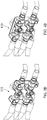
- Figure 3A shows an exploded view of a torque-resisting hose mounting 310 according to an embodiment of the invention, which is similar to the torque-resisting hose mounting of Figure 1 .
- Figure 3B shows the hose mounting of Figure 3A assembled and secured to a vehicle.
- FIG. 3A the sub-components of the torque-resisting hose mounting 310 are labelled with a part number and a letter. Sub-components that have the same number are the same type of part. Different letters are used to uniquely identify parts that are of the same type.
- the torque-resisting hose mounting 310 of Figure 3A includes the following sub-components:
- Rubber clamps correspond to the clamp jaws 36, 39, 53, 56 in Figure 1 , and can be considered as outer clamp jaws in that they are furthest from the flat metal connecting plates 4A, 4B.
- Each of these rubber clamps 5B, 5D, 5F, 5H have a circular cross-section recess in this example.
- each of these inner rubber clamps 5A, 5C, 5E, 5G have a fully enclosed circular cross-section bore for communicating fluid from a hydraulic tube 3A, 3B, 3C, 3D through the rubber clamp 5A, 5C, 5E, 5G to a cross coupling 2A, 2B.
- each of the inner clamps has a circular cross-section protrusion on an outer surface of the clamp ("outer" in that it is furthest from the flat metal connecting plates 4A, 4B).
- the circular cross-section protrusions on the inner rubber clamps 5A, 5C, 5E, 5G align and register with the circular cross-section recesses on the outer rubber clamps 5B, 5D, 5F, 5H when the rubber clamps are secured together.
- the screw-in fittings 1A, 1B can be used to secure the torque-resisting hose mounting 310 to a panel 325, such as a panel of a vehicle.
- Each of the screw-in fittings 1A, 1B has an axial dimension about which the associated cross coupling 2A, 2B could rotate if it were not secured.
- the axial dimension defines a potential horizontal axis of rotation of the cross coupling 2A, 2B. As indicated above, such rotation can lead to undesired leaks.
- the presence of the flat metal connecting plates 4A, 4B can reduce or prevent the rotation of the cross couplings 2A, 2B about this horizontal axis, especially when the hydraulic tubes 3A and 3B (and 3C and 3D) are differentially pressurized.
- Figure 4A shows an exploded view of a torque-resisting hose mounting 410 according to an embodiment of the invention, which is similar to the torque-resisting hose mounting of Figure 3A .
- Figure 4B shows the hose mounting of Figure 4A assembled and secured to a vehicle.
- the two flat metal connecting plates (items 4A and 4B in Figure 3A ), have been replaced with one plate 4A.
- the plate 4A is an example of a rigidifying member.
- the single rigidifying plate 4A interconnects four clamps.
- the four clamps are provided by the items labelled 5A-5H in Figure 4A , as described above with reference to the corresponding components of Figure 3A .
- the plate 4A of Figure 4A can interconnect clamps that are offset from each other in two dimensions.
- the two dimensions are transverse to each other, and can be generally orthogonal to each other.
- the plate 4A has an aperture 415 through which a connection to the cross couplings 2A, 2B can be made.
- the screw-in fittings 1A, 1B (or any other fastening means) can pass through the aperture 415 to secure the hose mounting 410 to a vehicle.
- the connection through the aperture 415 may provide a fluidic connection to or from the hose mounting 410.
- the plate 4A has two round holes and two slotted holes, through which fasteners can pass to secure the clamps 5A-H to the plate 4A.
- the fasteners are provided by nut and bolt combinations 8A-D, 9A-D.
- the slotted holes are elongated in a dimension that is towards a corresponding round hole. In this way, relative spacing of the clamps 5A-H can be adjusted by varying the position of the slotted holes through which the fasteners are located.
- the plate 4A can have other structures / arrangements that allow the position on the rigidifying member at which the clamps 5A-H to be variable with respect to each other.
- the clamps 5A-H are fixedly secured to the connecting plates 4A, 4B when the hose mounting is in an assembled configuration.
- the connecting plates 4A, 4B have a structure that allows the position on the connecting plates 4A, 4B at which the clamps 5A-H are to be fixedly secured to be variable with respect to each other.
- This structure may include both round and slotted holes through which fasteners can pass to secure the clamps 5A-H to the connecting plates 4A, 4B.
- the rigidifying member may comprise a weld nut attached to the rigidifying member at the location of the round hole.
- the weld nut can be used to secure a bolt in a desired position.
- this would mean that the number of lock nuts would reduce to two because lock nuts 9C and 9B would not be required.
- spring washers can be used as part of the fastening means that includes the weld nuts - for instance, instead of the normal washers indicated by 7B and 7C at the head of the bolts 8B, 8C that are to be secured to the weld nuts.
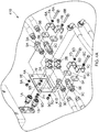
- FIG. 5 shows schematically a baling machine 500 that has a torque-resisting hose mounting 510 according to an embodiment of the invention mounted thereon.
- hoses 511, 512, 513, 514 Shown in Figure 5 are four hoses 511, 512, 513, 514 that are connected to the torque-resisting hose mounting 510 in the same way as described above.
- the hoses 511, 512, 513, 514 are used or provide fluid to actuators (not shown) that are associated with walls of a bale chamber. In this way, the walls can be moved to increase or decrease the volume of the bale chamber.
Landscapes
- Engineering & Computer Science (AREA)
- General Engineering & Computer Science (AREA)
- Mechanical Engineering (AREA)
- Mining & Mineral Resources (AREA)
- Civil Engineering (AREA)
- Structural Engineering (AREA)
- Supports For Pipes And Cables (AREA)
Abstract
Description
- The invention relates to a torque-resisting hose mounting.
- Typically a fluid power circuit employed in a vehicle includes a number of flexible hoses that are used to convey pressurized fluid in the power circuit. In a hydraulic power circuit, as is often employed in vehicle engineering, the hoses may be described as semi-rigid. Thus they are relatively thick-walled, sometimes armoured, hoses that tolerate the fluid pressures generated in the circuit.
- The pressure of fluid in a vehicle hydraulic circuit may change abruptly. Hydraulic hoses while stiffer than some other designs of hose are nonetheless sufficiently flexible that when a significant change of the pressure of hydraulic fluid occurs the hoses flex, expand or contract diametrically, and/or lengthen or shorten, under the influence of the pressure of the hydraulic fluid.
- The design of a hydraulic circuit used in a vehicle may include measures aimed at avoiding problems caused by such pressure changes. Thus for example a hydraulic hose may be designed to include a bend that accommodates changes in the length of a hose; and parts of the hose that might flex or expand when fluid pressure inside it increases may be routed to avoid fouling or chafing on other parts of the vehicle.
- Such steps can be effective over the length of a hose away from its ends; but problems arise at the ends of a hose. This is because each end of a hydraulic hose is connected to another component, such as a hose union or a hose termination or cap.
- Often the hose unions or terminations are not fixed to rigid parts of the vehicle and instead are supported essentially by the hoses that are connected to them.
- A pair of hoses may be connected respectively to the ends of a double-acting hydraulic actuator such as a ram or other extensible and retractile element. Operation of the actuator to extend or retract under the influence of the pressurized fluid in the hoses causes the pressure in one hose to increase while the pressure in the other hose decreases. At the ends of the hoses remote from the actuator such differential pressurizing leads to the generation of torques in the components such as unions and terminations. The torques cause the unions or terminations to rotate. This in turn induces leaks and other failures in the connections between the hoses and the unions or terminations.
- Such modes of failure are significantly problematic, as they can compromise the performance of e.g. a double-acting actuator connected to the hoses. Depending on the nature and purpose of the actuator this could be merely inconvenient, or it may have a seriously deleterious effect on vehicle performance or safety.
- Leaks of hydraulic fluid also necessitate replenishment of the fluid power system; may lead to slip accidents or fires; and create a need for cleaning of the internal parts of a vehicle. Indeed some hydraulic fluids are chemically aggressive and may attack the materials of other parts of a vehicle, so cleaning of leaked hydraulic fluid is important even if this means dismantling part of the vehicle. Also virtually all hydraulic fluids are toxic to humans and animals and should not be allowed to spill outside a vehicle. This is an especially important requirement if the vehicle is intended for use on a farm or in an environmentally sensitive location.
- An aim of the invention is to reduce or eliminate one or more problems of prior art fluid power hose arrangements as explained.
- Prior art solutions to the problems include those disclosed in publications nos
US 5316346 A ,DE8801061 U1 ,US 3999784 B andCN 204547827 U . All these publications describe arrangements for bracing a tube or pipe mounting. The use of bracing or fixing arrangements is costly in terms of engineering complexity, parts inventories and machine servicing time. - According to the invention in a broad aspect there is provided a torque-resisting hose mounting for attenuating torque arising when at least first and second flexible, fluid-carrying hoses each connected in a fluid-communicating manner with a pipe fitting are differentially pressurized, the torque-resisting hose mounting comprising:
- a. a first pipe fitting to which the first flexible, fluid-carrying hose is directly or indirectly connected;
- b. a second pipe fitting to which the second flexible, fluid-carrying hose is directly or indirectly connected;
- c. a first clamp gripping the first, flexible fluid-carrying hose or a first extension member connected thereto;
- d. a second clamp gripping the second rigid pipe flexible fluid-carrying hose or a second extension member connected thereto; and
- e. a rigidifying member interconnecting the first and second clamps.
- Such a mounting advantageously prevents or at least reduces problems of the kinds outlined above, without requiring that any part of the mounting is secured to or otherwise braced by a rigid feature such as a machine frame or vehicle chassis. The torque attenuation can arise partly because the connection between the first and second clamps permits oppositely acting torques, generated respectively by the first and second hoses as a double-acting actuator is energised, to cancel one another out, or largely cancel one another out. As a result the mounting remains essentially stationary even though it is not braced in any way.
- The mounting also is effective when only one of the pair of flexible, fluid-carrying hoses is pressurized or otherwise subjected to a change in the pressure of the fluid it carries. In such a situation the rigid connection between the first and second clamps reduces or prevents rotation of the clamp that is connected to the hose in question.
- The rigidifying member may be e.g. a metal or other rigid material plate.
- Preferably the first extension when present includes a first rigid pipe connecting the first pipe fitting and the first hose in fluid-transferring communication with one another; and the second extension when present includes a second rigid pipe connecting the second pipe fitting and the second hose in fluid-transferring communication with one another.
- In preferred embodiments of the invention the first rigid pipe is of lesser diameter than the first hose and the second rigid pipe is of lesser diameter than the second hose.
- These arrangements permit reliable securing of the clamps. Connections between the flexible hoses and the rigid pipes may as needed be employed in order to accommodate the indicated diameter variations.
- Further preferably the first clamp includes a first pair of resiliently deformable clamp jaws between which the first rigid pipe is gripped and defining a through-going circular cross-section bore for receiving the first rigid pipe; and the second clamp includes a second pair of resiliently deformable clamp jaws between which the second rigid pipe is gripped and defining a through-going, elongate slot for receiving the second rigid pipe.
- Such features of the clamps permit the hose mounting to accommodate manufacturing and tolerancing variations in the components of a hose or pipe network in which the mounting is used. In particular the slot allows to take account of the point at which the second hose or its associated extension passes between the jaws of the second clamp to suit the precise requirements.
- The resulting variability of the part of the second clamp that clamps the second hose or extension also means that the mounting may be used to secure a variety of differing designs of hose or pipe network.
- In embodiments described herein preferably the rigidifying member is connected to a respective first side of each of the first and second clamps. This is a convenient arrangement that is quick and easy to assemble and dismantle when required.
- Further preferably each of the first and second clamps includes a respective clamp brace juxtaposed to the clamp on the opposite side to the connection of the rigidifying member; and each of the first and second clamps includes a respective fastener extending from one side of the clamp to another secure the clamp brace and the rigidifying member one to the other against the resilient deformability of the clamp and with the clamp trapped therebetween. Such trapping of the clamp in turn traps the flexible fluid-carrying hose or an extension secured thereto on assembly of the parts of the mounting together.
- As a result the assembly of the mounting involves a simple series of positive location steps that permit rapid, reliable construction of a hose or pipe network.
- One preferred form of fastener is a nut and bolt combination the bolt of which passes through apertures in the rigidifying member, the clamp jaws and the clamp brace to be threadedly received in the nut on the exterior of the mounting. Another example of a fastener that is suitable is a bolt or screw that extends as described above and is threadedly received in a threaded bore formed in or secured to one of the rigidifying member or the clamp brace. Clips, overlocking lever fasteners, screw cramps and various other forms of fastener also are possible.
- In preferred embodiments at least one said clamp brace includes at least one side wall extending from the clamp brace towards a said rigidifying member externally of the clamp. Such a feature limits the clamping force that can be applied by each clamp, by reason of the side wall limiting the extent to which the clamp jaws may be compressed together. This in turn protects the clamped hose or extension from being crushed on tightening of the clamp.
- In practical embodiments a pair of the side walls may be provided.
- Optionally the first and second pipe fittings may be respective pipe terminations. Alternatively the first and second pipe fittings are respective pipe unions. When configured as pipe unions the first and second pipe fittings may be e.g. straight (two-pipe) unions, T-form (three-pipe) unions or cruciform (four-pipe) unions. Other types of unions also are possible within the scope of the invention.
- The first and second clamps may be fixedly secured to the rigidifying member when the hose mounting is in an assembled configuration. The rigidifying member can also have a disassembled (or partially assembled) configuration, in which the rigidifying member has a structure that allows the position on the rigidifying member at which the clamps are to be fixedly secured to be variable with respect to each other. This structure may include both round and slotted holes through which fasteners can pass to secure the clamps to the rigidifying member.
- Conveniently the first flexible, fluid-carrying hose is connected to provide pressurized fluid to a first end of a double-acting fluid actuator; and the second flexible, fluid-carrying hose is connected to provide pressurized fluid to a second end of the double-acting fluid actuator. However the hoses of the mounting of the invention need not be connected in this manner; and instead can be connected to a wide variety of other parts of a fluid power circuit.
- The invention also resides in a hose or pipe network including any first torque-resisting hose mounting disclosed herein, wherein the first pipe fitting is a pipe union to which is additionally connected a third flexible, fluid-carrying hose; wherein the second pipe fitting is a pipe union to which is additionally connected a fourth flexible, fluid-carrying hose; and wherein the hose or pipe network includes a second torque-resisting hose mounting comprising:
- f. the first pipe fitting;
- g. the second pipe fitting;
- h. a third clamp gripping the third rigid pipe or a third extension connected thereto;
- i. a fourth clamp gripping the fourth rigid pipe or a fourth extension connected thereto; and
- j. a rigidifying member interconnecting the third and fourth clamps.
- Thus the invention extends to a hose or pipe network in which a hose mounting according to the invention effectively is duplicated in order to provide connections for four flexible hoses.
- Such an arrangement may reliably provide fluid power to two double-acting actuators. In embodiments the pairs of flexible hoses connected respectively to the two double-acting actuators may each be supplied from a common pair of hose unions as described herein. To this end preferably the third and fourth flexible, fluid-carrying hoses are capable of being differentially pressurized.
- A single rigidifying member may interconnect each of the first, second, third and fourth clamps. One or more of the first, second, third and fourth clamps may be offset from each other in two dimensions. The two dimensions may be transverse or orthogonal to each other. The single rigidifying member may comprise an aperture through which a connection to the first pipe fitting and / or the second pipe fitting can be made.
- In addition the invention resides in a torque-resisting hose mounting as defined herein and/or a hose or pipe network as defined herein, when installed in or forming part of a vehicle and when connected to a source and/or a drain of pressurized fluid, especially hydraulic oil. Such a vehicle non-exclusively is or includes an agricultural vehicle, especially a baling machine.
- There now follows a description of a preferred embodiment of the invention, by way of non-limiting example, with reference being made to the accompanying drawings in which:
-
Figure 1 that shows a perspective view of part of a fluid power hose/pipe network, according to the invention, including a torque-resisting hose mounting according to the invention; -
Figure 2 shows in schematic, partly broken-away view of a vehicle, in the form of a baling machine, according to the invention; -
Figure 3A shows an exploded view of a torque-resisting hose mounting according to an embodiment of the invention; -
Figure 3B shows the hose mounting ofFigure 3A assembled and secured to a vehicle; -
Figure 4A shows an exploded view of a torque-resisting hose mounting according to another embodiment of the invention; -
Figure 4B shows the hose mounting ofFigure 4A assembled and secured to a vehicle; and -
Figure 5 shows schematically a baling machine that has a torque-resisting hose mounting according to an embodiment of the invention mounted thereon. - Referring to
Figures 1 and2 of the drawings a torque-resisting hose mounting 10 according to the invention includes at least first and second fluid-carryinghoses hoses -
First hose 11 at oneend 11a is connected to a first pipe fitting in the form of afirst pipe union 16 the arrangement of which is described in more detail below.Second hose 12 terminates in a similar manner at asecond pipe union 22. -
Third hose 13 is connected in a similar manner to the foregoing to an opposite side offirst pipe union 16 tofirst hose 11; andfourth hose 14 is similarly connected to an opposite side tosecond hose 12 ofsecond pipe union 22. - The
various hoses hoses respective pairs - One way this may occur is by reason of the first and
second hoses Figure 2 to respective ends of a first, double-actinghydraulic actuator 17 forming part of avehicle 100. - The
actuator 17 in a conventional manner includes acylindrical actuator body 18 and an extensible andretractile actuator rod 19. An otherwise free end of thecylindrical body 18 is secured to e.g. arigid frame member 21 forming part of thevehicle 100. An otherwise free end of theactuator rod 19 is secured to a moveable part of thevehicle 100 that it is required from time to time to move under the influence of theactuator 17. The moveable part is omitted fromFigure 2 and may take any of a variety of forms. - The
actuator 17 as is well known operates by causing controlled extension and retraction of theactuator rod 19. When extension is required controllable elements in the fluid power circuit cause fluid in thesecond hose 12 to become pressurized, thereby driving theactuator rod 19 outwardly from thecylindrical body 18. - Such movement of the
actuator rod 19 is accommodated by simultaneous depressurizing or draining of thefirst hose 11. - Pressurizing of
second hose 12 and depressurizing offirst hose 11 are effected through alterations in the pressure of fluid in supply pipes orhoses Figure 2 to the remainder of the fluid power circuit. The precise means through which this can be achieved are known to the person of skill in the art and are not described in detail herein. - Retraction of the
actuator rod 19 is effected by reversing the pressurizing and depressurizing of the flexible first andsecond hoses first hose 11 is pressurized andsecond hose 12 is depressurized. This condition may be achieved through operation of the aforesaid controllable parts of the fluid power circuit and result in fluid insupply hose 23 being pressurized and the pressure of fluid insupply hose 24 reducing. - The tendency of the
first pipe union 16 to rotate is beneficially counteracted in the arrangement of the invention through the presence of first andsecond clamps plate 33 that interconnects the first andsecond clamps -
First clamp 31 in the illustrated embodiment includes a first pair ofclamp jaws - Each
jaw - A respective semicircular cross-section first clamp recess, that is not visible in the image of
first clamp 31 inFigure 1 , extends along each of the rectangular faces of thejaws - The semicircular first clamp recesses are in register with one another when the
jaws Figure 1 and thereby define a through-going circular cross-section bore. A first,rigid pipe 37 defines a hose extension extending from theend 11a offlexible hose 11 along the interior of the circular cross-section bore such that it is encircled and gripped by theclamp jaws -
Second clamp 32 is formed somewhat similarly tofirst clamp 31, in that a second pair ofclamp jaws jaws - Each of the rectangular faces is formed with an ovoid cross-section recess extending along its length. As a result when the
jaws first clamp 31. - A second,
rigid pipe 41 defines a hose extension extending from theend 12a of secondflexible hose 12 that lies adjacent thesecond clamp 32 along the interior of the oval cross-section slot such that it is enclosed and gripped by theclamp jaws rigid pipe 41 is similar to the gripping of firstrigid pipe 37 except that the oval cross-section of the slot in which it is gripped accommodates variations in the vertical position of the secondrigid pipe 41 relative to the firstrigid pipe 37. - The recesses in the
jaws rigid pipes second clamps ends flexible hoses ends - The
rigid plate 33 is in the illustrated embodiment an elongate rectangle formed from a metal such as a steel, or from another rigid material. The rigid plate may take any of a range of forms and is not limited to the plate-like shape illustrated. Numerous variations will occur to the person of skill in the art. - The
rigid plate 33 extends vertically in use of the illustrated embodiment to interconnect the first andsecond clamps plate 33 is secured adjacent each of its ends to a respective one of theclamps - The
respective bolts 42, 43 extend through thejaws second clamps jaws rigid pipes - Each of the
bolts 42, 43 is threadedly engaged with a nut, that is not visible inFigure 1 (although corresponding nuts are shown inFigure 3A withreference numbers 9A-D), provided on the side of therigid plate 33 lying remote from the associated first orsecond clamp rigid plate 33 is perforated to permit the bolts to extend through it. Screwing of eachbolt 41, 42 into the nut as a result compresses thejaws clamp - In
Figure 2 the first bolt 42 is positioned to lie above the adjacentrigid pipe 37 in use of the hose mounting 10 and thesecond bolt 43 lies below therigid pipe 41; but this need not be the case. On the contrary, the bolts may be provided in any of a variety of positions. - As an alternative to the provision of a separate nut as described, the perforations of the
rigid plate 33 may be provided with internal threads, as the person of skill in the art readiy will be able to envisage. A further possibility, that the person of skill in the art also will readily be able to embody, is to use so-called "weld nuts" secured by welding to the face of therigid plate 33 that lies remote from theclamps - Each of the first and
second clamps respective clamp brace clamp brace bolts 42, 43 to extend therethrough. On assembly of the mounting 10 eachclamp brace bolt 42, 43 passing through it and theadjacent clamp jaw bolts 42, 43. - Each of the clamp braces 44, 46 is in the preferred embodiment formed as a U-section member as illustrated, with a respective pair of
optional side walls respective clamp brace rigid plate 33. Theside walls rigid plate 33 on tightening of thebolts 42, 43 to limit the extent to which theclamp jaws rigid pipes - The provision of a pair of the side walls in each case helps to ensure that the clamping forces are applied evenly to the
clamp jaws - Operation of the hose mounting 10 in the application described herein is as described above, with fluid in the
supply hoses vehicle 100 in which the mounting 10 is used. As explained such operation has tendency to cause rotation of theunions unions unions - The foregoing description relates primarily to the situation arising when a single actuator, such as
actuator 17, is provided. In the embodiment illustrated in the figures however an optional second, double-actingactuator 26 is additionally provided at a location in thevehicle 100 that is spaced from the position ofactuator 17. - Second double-acting
actuator 26, having acylindrical actuator body 27 and extensible andretractile actuator rod 28 is secured in an identical or similar manner to double-actingactuator 17. Thus an end of thecylindrical body 27 is secured to e.g. a furtherrigid frame member 29. The otherwise free end ofactuator rod 28 is secured to a further moveable part that also is omitted fromFigure 2 . The further moveable part may take a variety of forms. - Third and fourth flexible, fluid carrying
hoses second actuator 26 in a similar manner to that of first and second flexible, fluid-carryinghoses fourth hose 14 and depressurizing ofthird hose 13 causes extension of theactuator rod 28; and pressurizing ofthird hose 13 and depressurizing offourth hose 14 causes retraction of theactuator rod 28. - Such pressurizing and depressurizing of fluid in the
hoses hoses actuator 26 respectively to theunions - To this end the
unions unions supply hoses hoses hoses - The third and
fourth hoses respective unions second hoses - Thus there are provided third and
fourth clamps third hose 13 to theunion 16 and thefourth hose 14 to theunion 22. -
Third clamp 52 includes fifth andsixth clamp jaws first clamp 31. Theclamp jaws bolt combination 57 are compressed in use between arigid plate 58 and aclamp brace 59. -
Clamp brace 59 includesoptional side walls 61, 62 extending towards therigid plate 58, in like manner to the arrangement of the first clamp. A hose extension in the form of arigid pipe 63 of lesser diameter than thethird hose 13 to which it is communicatingly connected is clamped between the fifth andsixth clamp jaws -
Fourth clamp 53 includes seventh andeighth clamp jaws second clamp 32. Theclamp jaws bolt combination 67 are compressed in use betweenrigid plate 58 and afurther clamp brace 68. -
Clamp brace 68 includesoptional side walls rigid plate 58, in like manner to the arrangement of thesecond clamp 32. A hose extension in the form of arigid pipe 72 of lesser diameter than thefourth hose 14 to which it is communicatingly connected is clamped between the seventh andeighth clamp jaws rigid pipe 41 the oval cross-section of the slot permits tolerancing in the position of the fourthrigid pipe 72 relative to thirdrigid pipe 63 to be accommodated. -
Rigid plate 58 interconnects the third andfourth clamps rigid plate 33 interconnecting the first andsecond clamps rigid plate 33,plate 58 may take a variety of forms that may differ from that shown. - Also in like manner to the arrangement of the first and
second clamps rigid pipes fourth hoses - Operation of the third and
fourth clamps unions - As mentioned the presence of the third and
fourth hoses second hoses unions - Furthermore the
flexible hoses supply hoses unions 16 and/or 22 could in embodiments of the invention be replaced by hose terminations such as end caps that close off thehoses Figure 1 , in accordance with the principles of the invention as explained herein. It would readily be within the ability of the person of skill in the art to devise such arrangements. Hose terminating also may be created in an arrangement such as that ofFigure 1 when the pressure of fluid in thesupply hoses hoses - One example of a
vehicle 100 in which the hose mounting of the invention may be employed is a baling machine as illustrated schematically inFigure 2 . As is well known such a machine typically is a wheeled vehicle that is towed behind an agricultural tractor and that picks upstraw 101 or other material to be baled that is lying in windrows in a field. Such a machine forms the straw into bales that are ejected via abale chute 102 at the rear of the machine. - As is apparent from the cut-away section of
Figure 2 the hose mounting 10 of the invention may readily be incorporated into such amachine 100 and operatively connected, as signified by the arrows in the figure, to a fluid power circuit forming part of thevehicle 100. - The invention however is not limited to installations of the hose mounting in a vehicle such as a baling machine as shown. On the contrary it may be included in a wide variety of vehicular and non-vehicular machines, including tractors and harvesting machines.
- Vehicles as fall within the scope of the invention may include control elements and systems for controlling the pressure of fluid in parts of a fluid power circuit in which the mounting 10 of the invention is installed. Such control elements and systems may include programmable devices such as microprocessors, electronic controllers, hard-wired circuits, hydraulic, electrical and/or electrohydraulic logic circuits, gates and switches and derivatives of such features.
- The fluid power circuit of a vehicle such as
vehicle 100 typically but not necessarily would include one or more pumps, regulators, valves and filters. These have been omitted from the figures and would be present in practical embodiments to the extent required for successful achievement of the operational objectives of thevehicle 100. -
Figure 3A shows an exploded view of a torque-resisting hose mounting 310 according to an embodiment of the invention, which is similar to the torque-resisting hose mounting ofFigure 1 .Figure 3B shows the hose mounting ofFigure 3A assembled and secured to a vehicle. - In
Figure 3A the sub-components of the torque-resisting hose mounting 310 are labelled with a part number and a letter. Sub-components that have the same number are the same type of part. Different letters are used to uniquely identify parts that are of the same type. - The torque-resisting hose mounting 310 of
Figure 3A includes the following sub-components: - Item 1 - screw-in fitting - quantity 2 - (A and B).
- Item 2 - cross coupling - quantity 2 - (A and B). These parts correspond to the
pipe unions Figure 1 . - Item 3 - hydraulic tube - quantity 4 - (A; B; C and D). These parts correspond to the ends of the
hoses Figure 1 . - Item 4 - flat metal connecting plate - quantity 2 - (A and B). These parts correspond to the
rigid plates Figure 1 , although inFigure 3A eachplate 4A-B has a round hole and a slotted hole as will be discussed below with reference toFigure 4A . - Item 5 - rubber clamp - quantity 8 - (A; B; C; D; E; F; G and H).
- Four of these rubber clamps (5B, 5D, 5F, 5H) correspond to the
clamp jaws Figure 1 , and can be considered as outer clamp jaws in that they are furthest from the flatmetal connecting plates - The other four of these rubber clamps (5A, 5C, 5E, 5G) provide the functionality of the
clamp jaws Figure 1 , and can be considered as providing the functionality of inner clamp jaws because they are closest to the flatmetal connecting plates Figure 1 , each of these inner rubber clamps 5A, 5C, 5E, 5G have a fully enclosed circular cross-section bore for communicating fluid from ahydraulic tube rubber clamp cross coupling metal connecting plates - The circular cross-section protrusions on the inner rubber clamps 5A, 5C, 5E, 5G align and register with the circular cross-section recesses on the outer rubber clamps 5B, 5D, 5F, 5H when the rubber clamps are secured together.
- Item 6 - Metal u-bracket for over the rubber clamp - quantity 4 - (A; B; C and D). These parts correspond to the clamp braces 44, 46, 59, 68 of
Figure 1 . - Item 7 - Washer - quantity 8 - (A; B; C; D; E; F; G and H). These parts are not described with reference to
Figure 1 . As is known in the art, thewashers 8A-H can assist with theadjacent nut 9A-D or head of thebolt 8A-D providing an even distribution of pressure on the respective connectingplate 4A-B or themetal u-bracket 6A-D. - Item 8 - Bolt - quantity 4 - (A; B; C and D). These parts correspond to the
bolts Figure 1 . - Item 9 - Lock nut - quantity 4 - (A, B, C and D). As indicated above, the corresponding nuts that are used in the mounting of
Figure 1 are not visible inFigure 1 . - The screw-in
fittings 1A, 1B can be used to secure the torque-resisting hose mounting 310 to apanel 325, such as a panel of a vehicle. Each of the screw-infittings 1A, 1B has an axial dimension about which the associatedcross coupling cross coupling metal connecting plates cross couplings hydraulic tubes - Provided below in an example of how the sub-components of the torque-resisting hose mounting 310 of
Figure 3A can be assembled: - i. Start with confirm item 1 - screw-in fitting - number 2x.
- ii. Assemble
Item item 2A - Cross coupling. - iii. Assemble
Item item 2B - Cross coupling. - iv. Mounting the
Cross coupling 2A on the screw-in fitting 1A - horizontal. - v. Mounting the
Cross coupling 2B on the screw-infitting 1B - horizontal. - vi. Placing on
bolt 8A -washer 7A -U-bracket 6A - rubberouter clamp jaw 5B (that can be considered as having a half rounding overhydraulic tube 3A) - rubberinner clamp jaw 5A (that can also be considered as having a rounding over thetube 3A) - then the slotted hole of the flatmetal connecting plate 4A - again awasher 7E - and finallylocknut 9A. - vii. Same assembly for
bolt 8B -washer 7B positioning -U-bracket 6B - rubberouter clamp jaw 5D (that can be considered as having a half rounding overhydraulic tube 3B) - rubberinner clamp jaw 5C (that can be considered as having a rounding over thetube 3B) - then the round hole of the flatmetal connecting plate 4A -back washer 7F and finally locknut 9B. - viii. Same assembly for
bolt 8D -washer 7D places -U-bracket 6D - rubberouter clamp jaw 5H (that can eb considered as having a semi-rounding overhydraulic tube 3D) - rubberinner clamp jaw 5G (that can be considered as having a rounding over thetube 3D) - then the slotted hole of the flatmetal connecting plate 4B - again awasher 7H and to place as thelast lock nut 9D. - ix. Same mounting for
bolt 8C -washer 7C places -U-bracket 6C - rubberouter clamp jaw 5F (that can be considered as having a semi-rounding overtube 3C) - rubberinner clamp jaw 5E (that can be considered as having a rounding over thetube 3C) - then the round hole of the flatmetal connecting plate 4B - back awasher 7G - and to place as thelast lock nut 9C. -
Figure 4A shows an exploded view of a torque-resisting hose mounting 410 according to an embodiment of the invention, which is similar to the torque-resisting hose mounting ofFigure 3A .Figure 4B shows the hose mounting ofFigure 4A assembled and secured to a vehicle. - In
Figure 4A the two flat metal connecting plates (items Figure 3A ), have been replaced with oneplate 4A. Theplate 4A is an example of a rigidifying member. In this example, thesingle rigidifying plate 4A interconnects four clamps. The four clamps are provided by the items labelled 5A-5H inFigure 4A , as described above with reference to the corresponding components ofFigure 3A . In this way, theplate 4A ofFigure 4A can interconnect clamps that are offset from each other in two dimensions. InFigure 4A the two dimensions are transverse to each other, and can be generally orthogonal to each other. - In the example of
Figure 4A , theplate 4A has anaperture 415 through which a connection to thecross couplings fittings 1A, 1B (or any other fastening means) can pass through theaperture 415 to secure the hose mounting 410 to a vehicle. In some examples, the connection through theaperture 415 may provide a fluidic connection to or from the hose mounting 410. - The
plate 4A has two round holes and two slotted holes, through which fasteners can pass to secure theclamps 5A-H to theplate 4A. In this example, the fasteners are provided by nut andbolt combinations 8A-D, 9A-D. The slotted holes are elongated in a dimension that is towards a corresponding round hole. In this way, relative spacing of theclamps 5A-H can be adjusted by varying the position of the slotted holes through which the fasteners are located. It will be appreciated that theplate 4A can have other structures / arrangements that allow the position on the rigidifying member at which theclamps 5A-H to be variable with respect to each other. - In this way, the
clamps 5A-H are fixedly secured to the connectingplates plates plates clamps 5A-H are to be fixedly secured to be variable with respect to each other. This structure may include both round and slotted holes through which fasteners can pass to secure theclamps 5A-H to the connectingplates - For any of the examples disclosed herein that include a rigidifying member that has a round hole for receiving a bolt (such as the round holes in the plates shown in
Figures 3A and4A ), the rigidifying member may comprise a weld nut attached to the rigidifying member at the location of the round hole. In this way, the weld nut can be used to secure a bolt in a desired position. For the example ofFigure 4A , this would mean that the number of lock nuts would reduce to two becauselock nuts bolts -
Figure 5 shows schematically a balingmachine 500 that has a torque-resisting hose mounting 510 according to an embodiment of the invention mounted thereon. - Shown in
Figure 5 are fourhoses hoses - The listing or discussion of an apparently prior-published document in this specification should not necessarily be taken as an acknowledgement that the document is part of the state of the art or is common general knowledge.
- Preferences and options for a given aspect, feature or parameter of the invention should, unless the context indicates otherwise, be regarded as having been disclosed in combination with any and all preferences and options for all other aspects, features and parameters of the invention.
Claims (15)
- A torque-resisting hose mounting (10) for attenuating torque arising when at least first and second flexible, fluid-carrying hoses (11,12) each connected in a fluid-communicating manner with a pipe fitting (16,22) are differentially pressurized, the torque-resisting hose mounting (10) comprising:a. a first pipe fitting (16) to which the first flexible, fluid-carrying hose (11) is directly or indirectly connected;b. a second pipe fitting (22) to which the second flexible, fluid-carrying hose (12) is directly or indirectly connected;c. a first clamp (31) gripping the first flexible hose (11) or a first hose extension connected thereto;d. a second clamp (32) gripping the second flexible hose (12) or a second hose extension connected thereto; ande. a rigidifying member (33) interconnecting the first and second clamps (31,32).
- A torque-resisting hose mounting (10) according to Claim 1 wherein:the first hose extension when present includes a first rigid pipe (37) connecting the first pipe fitting (16) and the first hose (11) in fluid-transferring communication with one another; andthe second hose extension when present includes a second rigid pipe (41) connecting the second pipe fitting (22) and the second hose (12) in fluid-transferring communication with one another.
- A torque-resisting hose mounting (10) according to Claim 2 wherein the first rigid pipe (37) is of lesser diameter than the first hose (11) and the second rigid pipe (41) is of lesser diameter than the second hose (12).
- A torque-resisting hose mounting (10) according to Claim 2 or Claim 3 wherein:the first clamp (31) includes a first pair of resiliently deformable clamp jaws (34,36) between which the first rigid pipe (37) is gripped and defining a through-going circular cross-section bore for receiving the first rigid pipe (37); and / orthe second clamp (32) includes a second pair of resiliently deformable clamp jaws (38,39) between which the second rigid pipe (41) is gripped and defining a through-going, elongate slot for receiving the second rigid pipe (41).
- A torque-resisting hose mounting (10) according to any preceding claim wherein the rigidifying member (33) is connected to a respective first side of each of the first and second clamps (31,32).
- A torque-resisting hose mounting (10) according to Claim 5 when dependent from Claim 4 wherein each of the first and second clamps (31,32) includes a respective clamp brace (44,46) juxtaposed to the clamp on the opposite side to the connection of the rigidifying member (33), and wherein each of the first and second clamps (31,32) includes a respective fastener (42,43) extending from one side of the clamp to another to secure the clamp brace (44,46) and the rigidifying member (33) one to the other against the resilient deformability of the clamp (31,32) and with the clamp trapped therebetween.
- A torque-resisting hose mounting (10) according to Claim 6 wherein at least one said clamp brace (44,46) includes at least one side wall (47,48,49,51) extending from the clamp brace towards a said rigidifying member (33) externally of the clamp (31,32).
- A torque-resisting hose mounting (10) according to any preceding claim wherein the first and second pipe fittings (16,22) are respective pipe terminations.
- A torque-resisting hose mounting (10) according to any preceding claim wherein the first and second pipe fittings (16,22) are respective pipe unions.
- A torque-resisting hose mounting (10) according to any preceding claim wherein the first flexible, fluid-carrying hose (11) is connected to provide pressurized fluid to a first end (11a) of a double-acting fluid actuator (17); and the second flexible, fluid-carrying hose (12) is connected to provide pressurized fluid to a second end (12a) of the double-acting fluid actuator (17).
- A hose or pipe network including a first torque-resisting hose mounting (10) according to any of Claims 1 to 7, 9 or 10, wherein the first pipe fitting (16) is a pipe union to which is additionally connected a third flexible, fluid-carrying hose (13); wherein the second pipe fitting (22) is a pipe union to which is additionally connected a fourth flexible, fluid-carrying hose (14); and wherein the hose or pipe network includes a second torque-resisting hose mounting comprising:f. the first pipe fitting (16);g. the second pipe fitting (22);h. a third clamp (52) gripping the third rigid pipe (63) or a third extension connected thereto;i. a fourth clamp (53) gripping the fourth rigid pipe (72) or a fourth extension connected thereto; andj. a rigidifying member (58) interconnecting the third and fourth clamps (52,53).
- A hose or pipe network according to Claim 11, wherein a single rigidifying member interconnects each of the first, second, third and fourth clamps (31, 32, 52, 53).
- A hose or pipe network according to Claim 12, wherein the single rigidifying member comprises an aperture (415) through which a connection to the first pipe fitting (16) and / or the second pipe fitting (22) can be made.
- A hose or pipe network according to any one of Claims 11 to 13 wherein the third and fourth flexible, fluid-carrying hoses (13,14) are capable of being differentially pressurized.
- A vehicle (100) including a torque-resisting hose mounting (10) according to any of Claims 1 to 10 and/or a hose or pipe network according to any one of Claims 11 to 14, and connected to a source and/or a drain of pressurized fluid.
Priority Applications (3)
| Application Number | Priority Date | Filing Date | Title |
|---|---|---|---|
| EP18204220.0A EP3647641B1 (en) | 2018-11-02 | 2018-11-02 | A torque-resisting hose mounting |
| PCT/EP2019/079701 WO2020089315A1 (en) | 2018-11-02 | 2019-10-30 | A torque-resisting hose mounting |
| US17/245,879 US20210246632A1 (en) | 2018-11-02 | 2021-04-30 | Torque-resisting hose mounting |
Applications Claiming Priority (1)
| Application Number | Priority Date | Filing Date | Title |
|---|---|---|---|
| EP18204220.0A EP3647641B1 (en) | 2018-11-02 | 2018-11-02 | A torque-resisting hose mounting |
Publications (2)
| Publication Number | Publication Date |
|---|---|
| EP3647641A1 true EP3647641A1 (en) | 2020-05-06 |
| EP3647641B1 EP3647641B1 (en) | 2023-06-28 |
Family
ID=64172315
Family Applications (1)
| Application Number | Title | Priority Date | Filing Date |
|---|---|---|---|
| EP18204220.0A Active EP3647641B1 (en) | 2018-11-02 | 2018-11-02 | A torque-resisting hose mounting |
Country Status (3)
| Country | Link |
|---|---|
| US (1) | US20210246632A1 (en) |
| EP (1) | EP3647641B1 (en) |
| WO (1) | WO2020089315A1 (en) |
Citations (7)
| Publication number | Priority date | Publication date | Assignee | Title |
|---|---|---|---|---|
| US3999784A (en) | 1975-09-18 | 1976-12-28 | Caterpillar Tractor Co. | Tube clamp mounting |
| DE8801061U1 (en) | 1988-01-29 | 1989-06-01 | Robert Bosch Gmbh, 7000 Stuttgart | Cable assembly with flexible cable harnesses |
| US5316346A (en) | 1992-04-10 | 1994-05-31 | General Electric Company | Anti-rotation bracket for a flanged connection spaced from fixed structure |
| CN204547827U (en) | 2015-04-15 | 2015-08-12 | 陕西万里达铁路电气化器材有限公司 | A kind of bracket and registration arm bracing or strutting arrangement |
| US20150247591A1 (en) * | 2015-05-14 | 2015-09-03 | Caterpillar Inc. | System for retaining mulitple hoses |
| EP3379123A1 (en) * | 2017-03-16 | 2018-09-26 | Deere & Company | Clamp fastening device and work verhicle with such |
| WO2018184105A1 (en) * | 2017-04-04 | 2018-10-11 | Taimi R&D Inc. | Support assembly for swivellably supporting hydraulic lines |
Family Cites Families (9)
| Publication number | Priority date | Publication date | Assignee | Title |
|---|---|---|---|---|
| US3414220A (en) * | 1966-12-30 | 1968-12-03 | Hydro Craft Inc | Clamp means |
| US3592427A (en) * | 1969-01-09 | 1971-07-13 | Louis J Misuraca | Adaptable module, conduit and tube support |
| US3695563A (en) * | 1970-06-01 | 1972-10-03 | Theodore D Evans | Hydraulic line fitting support apparatus |
| US3782881A (en) * | 1971-11-09 | 1974-01-01 | American Standard Inc | Gas burner protective apparatus |
| US3751076A (en) * | 1971-12-10 | 1973-08-07 | Caterpillar Tractor Co | Collet hose bracket |
| US4775286A (en) * | 1988-02-05 | 1988-10-04 | J. I. Case Company | Hydraulic hose routing for tractor-mounted backhoe |
| DE69004287T2 (en) * | 1989-02-16 | 1994-02-24 | Kubota Kk | Hydraulic pipe arrangement for a backhoe. |
| US6561466B1 (en) * | 2002-02-20 | 2003-05-13 | Mitchell W. Myers | Interchangeable hose, cable, and conduit support mechanism |
| GB201202883D0 (en) * | 2012-02-20 | 2012-04-04 | Airbus Operations Ltd | Clamp block assembly |
-
2018
- 2018-11-02 EP EP18204220.0A patent/EP3647641B1/en active Active
-
2019
- 2019-10-30 WO PCT/EP2019/079701 patent/WO2020089315A1/en not_active Ceased
-
2021
- 2021-04-30 US US17/245,879 patent/US20210246632A1/en not_active Abandoned
Patent Citations (7)
| Publication number | Priority date | Publication date | Assignee | Title |
|---|---|---|---|---|
| US3999784A (en) | 1975-09-18 | 1976-12-28 | Caterpillar Tractor Co. | Tube clamp mounting |
| DE8801061U1 (en) | 1988-01-29 | 1989-06-01 | Robert Bosch Gmbh, 7000 Stuttgart | Cable assembly with flexible cable harnesses |
| US5316346A (en) | 1992-04-10 | 1994-05-31 | General Electric Company | Anti-rotation bracket for a flanged connection spaced from fixed structure |
| CN204547827U (en) | 2015-04-15 | 2015-08-12 | 陕西万里达铁路电气化器材有限公司 | A kind of bracket and registration arm bracing or strutting arrangement |
| US20150247591A1 (en) * | 2015-05-14 | 2015-09-03 | Caterpillar Inc. | System for retaining mulitple hoses |
| EP3379123A1 (en) * | 2017-03-16 | 2018-09-26 | Deere & Company | Clamp fastening device and work verhicle with such |
| WO2018184105A1 (en) * | 2017-04-04 | 2018-10-11 | Taimi R&D Inc. | Support assembly for swivellably supporting hydraulic lines |
Also Published As
| Publication number | Publication date |
|---|---|
| EP3647641B1 (en) | 2023-06-28 |
| US20210246632A1 (en) | 2021-08-12 |
| WO2020089315A1 (en) | 2020-05-07 |
Similar Documents
| Publication | Publication Date | Title |
|---|---|---|
| EP0002385B1 (en) | Double-walled fluid pressure line | |
| US9061223B2 (en) | Multi-port valve device with dual directional strainer | |
| CA2585935C (en) | Locking device for hydraulic attachment interface | |
| JP5290953B2 (en) | Semi-manual or fully automatic multi-coupling system and its mounting method | |
| EP3265680B1 (en) | Two-cylinder piston pump | |
| US10538892B2 (en) | Hydraulic impact hammer systems and methods | |
| EP3647641B1 (en) | A torque-resisting hose mounting | |
| DE69603024T2 (en) | COMPENSATOR AND VIBRATION DAMPER IN METAL FOR PIPELINE SYSTEMS | |
| KR200197257Y1 (en) | Tie-rod elastic pipe | |
| DE102013223060A1 (en) | Device for fastening of fluid conduit at flange of housing of hydraulic force-strengthened aggregate i.e. brake device for motor car, has connector is arranged between seal and bracket, which is secured at flange for holding fluid conduit | |
| KR102577182B1 (en) | Device mounting structure | |
| EP3101324B1 (en) | Pipe coupling with a sleeve unit | |
| DE102011007231B4 (en) | Wheel bearing arrangement, in particular wheel bearing arrangement for commercial vehicles | |
| EP2990709A1 (en) | Connection device for a media conveying conduit, and method for connecting a media-conveying conduit | |
| DE10147663B4 (en) | Pipe mount with an amplification arrangement in a motor vehicle | |
| EP1484544A1 (en) | Conduit feed-through for the installation of a sanitary tube through a wall | |
| EP1495231B1 (en) | Hydro damper | |
| DE102005052704A1 (en) | Expandable hydraulic valve stack | |
| EP1686305A1 (en) | Device for compensating the relative movement of two pipes that are to be connected in a pressure-tight way | |
| DE202009018707U1 (en) | Pipe connection system | |
| DE102015217786A1 (en) | Device for producing an axial connection, in particular in a refrigerant circuit of a motor vehicle | |
| KR20160059496A (en) | Hose connecting structure for hydraulic breaker | |
| DE102010061149A1 (en) | Device, particularly mobile structural unit for use with pressure compensating vessel for pressure compensation on part of unit such as on attachment of construction machine, has corresponding coupling element to one of connections | |
| CN210661786U (en) | Heating and ventilating connecting pipe with circumferential-longitudinal combined restoring force | |
| WO2007019989A1 (en) | Device and method for connecting a hydraulic hose to a connecting nipple |
Legal Events
| Date | Code | Title | Description |
|---|---|---|---|
| PUAI | Public reference made under article 153(3) epc to a published international application that has entered the european phase |
Free format text: ORIGINAL CODE: 0009012 |
|
| STAA | Information on the status of an ep patent application or granted ep patent |
Free format text: STATUS: THE APPLICATION HAS BEEN PUBLISHED |
|
| AK | Designated contracting states |
Kind code of ref document: A1 Designated state(s): AL AT BE BG CH CY CZ DE DK EE ES FI FR GB GR HR HU IE IS IT LI LT LU LV MC MK MT NL NO PL PT RO RS SE SI SK SM TR |
|
| AX | Request for extension of the european patent |
Extension state: BA ME |
|
| STAA | Information on the status of an ep patent application or granted ep patent |
Free format text: STATUS: REQUEST FOR EXAMINATION WAS MADE |
|
| 17P | Request for examination filed |
Effective date: 20201106 |
|
| RBV | Designated contracting states (corrected) |
Designated state(s): AL AT BE BG CH CY CZ DE DK EE ES FI FR GB GR HR HU IE IS IT LI LT LU LV MC MK MT NL NO PL PT RO RS SE SI SK SM TR |
|
| STAA | Information on the status of an ep patent application or granted ep patent |
Free format text: STATUS: EXAMINATION IS IN PROGRESS |
|
| 17Q | First examination report despatched |
Effective date: 20210326 |
|
| GRAP | Despatch of communication of intention to grant a patent |
Free format text: ORIGINAL CODE: EPIDOSNIGR1 |
|
| STAA | Information on the status of an ep patent application or granted ep patent |
Free format text: STATUS: GRANT OF PATENT IS INTENDED |
|
| INTG | Intention to grant announced |
Effective date: 20230119 |
|
| GRAS | Grant fee paid |
Free format text: ORIGINAL CODE: EPIDOSNIGR3 |
|
| GRAA | (expected) grant |
Free format text: ORIGINAL CODE: 0009210 |
|
| STAA | Information on the status of an ep patent application or granted ep patent |
Free format text: STATUS: THE PATENT HAS BEEN GRANTED |
|
| AK | Designated contracting states |
Kind code of ref document: B1 Designated state(s): AL AT BE BG CH CY CZ DE DK EE ES FI FR GB GR HR HU IE IS IT LI LT LU LV MC MK MT NL NO PL PT RO RS SE SI SK SM TR |
|
| REG | Reference to a national code |
Ref country code: CH Ref legal event code: EP |
|
| REG | Reference to a national code |
Ref country code: AT Ref legal event code: REF Ref document number: 1582949 Country of ref document: AT Kind code of ref document: T Effective date: 20230715 |
|
| REG | Reference to a national code |
Ref country code: IE Ref legal event code: FG4D |
|
| REG | Reference to a national code |
Ref country code: DE Ref legal event code: R096 Ref document number: 602018052366 Country of ref document: DE |
|
| REG | Reference to a national code |
Ref country code: LT Ref legal event code: MG9D |
|
| PG25 | Lapsed in a contracting state [announced via postgrant information from national office to epo] |
Ref country code: SE Free format text: LAPSE BECAUSE OF FAILURE TO SUBMIT A TRANSLATION OF THE DESCRIPTION OR TO PAY THE FEE WITHIN THE PRESCRIBED TIME-LIMIT Effective date: 20230628 Ref country code: NO Free format text: LAPSE BECAUSE OF FAILURE TO SUBMIT A TRANSLATION OF THE DESCRIPTION OR TO PAY THE FEE WITHIN THE PRESCRIBED TIME-LIMIT Effective date: 20230928 |
|
| REG | Reference to a national code |
Ref country code: NL Ref legal event code: MP Effective date: 20230628 |
|
| REG | Reference to a national code |
Ref country code: AT Ref legal event code: MK05 Ref document number: 1582949 Country of ref document: AT Kind code of ref document: T Effective date: 20230628 |
|
| PG25 | Lapsed in a contracting state [announced via postgrant information from national office to epo] |
Ref country code: RS Free format text: LAPSE BECAUSE OF FAILURE TO SUBMIT A TRANSLATION OF THE DESCRIPTION OR TO PAY THE FEE WITHIN THE PRESCRIBED TIME-LIMIT Effective date: 20230628 Ref country code: NL Free format text: LAPSE BECAUSE OF FAILURE TO SUBMIT A TRANSLATION OF THE DESCRIPTION OR TO PAY THE FEE WITHIN THE PRESCRIBED TIME-LIMIT Effective date: 20230628 Ref country code: LV Free format text: LAPSE BECAUSE OF FAILURE TO SUBMIT A TRANSLATION OF THE DESCRIPTION OR TO PAY THE FEE WITHIN THE PRESCRIBED TIME-LIMIT Effective date: 20230628 Ref country code: LT Free format text: LAPSE BECAUSE OF FAILURE TO SUBMIT A TRANSLATION OF THE DESCRIPTION OR TO PAY THE FEE WITHIN THE PRESCRIBED TIME-LIMIT Effective date: 20230628 Ref country code: HR Free format text: LAPSE BECAUSE OF FAILURE TO SUBMIT A TRANSLATION OF THE DESCRIPTION OR TO PAY THE FEE WITHIN THE PRESCRIBED TIME-LIMIT Effective date: 20230628 Ref country code: GR Free format text: LAPSE BECAUSE OF FAILURE TO SUBMIT A TRANSLATION OF THE DESCRIPTION OR TO PAY THE FEE WITHIN THE PRESCRIBED TIME-LIMIT Effective date: 20230929 |
|
| PG25 | Lapsed in a contracting state [announced via postgrant information from national office to epo] |
Ref country code: FI Free format text: LAPSE BECAUSE OF FAILURE TO SUBMIT A TRANSLATION OF THE DESCRIPTION OR TO PAY THE FEE WITHIN THE PRESCRIBED TIME-LIMIT Effective date: 20230628 |
|
| PG25 | Lapsed in a contracting state [announced via postgrant information from national office to epo] |
Ref country code: SK Free format text: LAPSE BECAUSE OF FAILURE TO SUBMIT A TRANSLATION OF THE DESCRIPTION OR TO PAY THE FEE WITHIN THE PRESCRIBED TIME-LIMIT Effective date: 20230628 |
|
| PG25 | Lapsed in a contracting state [announced via postgrant information from national office to epo] |
Ref country code: ES Free format text: LAPSE BECAUSE OF FAILURE TO SUBMIT A TRANSLATION OF THE DESCRIPTION OR TO PAY THE FEE WITHIN THE PRESCRIBED TIME-LIMIT Effective date: 20230628 |
|
| PG25 | Lapsed in a contracting state [announced via postgrant information from national office to epo] |
Ref country code: IS Free format text: LAPSE BECAUSE OF FAILURE TO SUBMIT A TRANSLATION OF THE DESCRIPTION OR TO PAY THE FEE WITHIN THE PRESCRIBED TIME-LIMIT Effective date: 20231028 |
|
| PG25 | Lapsed in a contracting state [announced via postgrant information from national office to epo] |
Ref country code: SM Free format text: LAPSE BECAUSE OF FAILURE TO SUBMIT A TRANSLATION OF THE DESCRIPTION OR TO PAY THE FEE WITHIN THE PRESCRIBED TIME-LIMIT Effective date: 20230628 Ref country code: SK Free format text: LAPSE BECAUSE OF FAILURE TO SUBMIT A TRANSLATION OF THE DESCRIPTION OR TO PAY THE FEE WITHIN THE PRESCRIBED TIME-LIMIT Effective date: 20230628 Ref country code: RO Free format text: LAPSE BECAUSE OF FAILURE TO SUBMIT A TRANSLATION OF THE DESCRIPTION OR TO PAY THE FEE WITHIN THE PRESCRIBED TIME-LIMIT Effective date: 20230628 Ref country code: PT Free format text: LAPSE BECAUSE OF FAILURE TO SUBMIT A TRANSLATION OF THE DESCRIPTION OR TO PAY THE FEE WITHIN THE PRESCRIBED TIME-LIMIT Effective date: 20231030 Ref country code: IS Free format text: LAPSE BECAUSE OF FAILURE TO SUBMIT A TRANSLATION OF THE DESCRIPTION OR TO PAY THE FEE WITHIN THE PRESCRIBED TIME-LIMIT Effective date: 20231028 Ref country code: ES Free format text: LAPSE BECAUSE OF FAILURE TO SUBMIT A TRANSLATION OF THE DESCRIPTION OR TO PAY THE FEE WITHIN THE PRESCRIBED TIME-LIMIT Effective date: 20230628 Ref country code: EE Free format text: LAPSE BECAUSE OF FAILURE TO SUBMIT A TRANSLATION OF THE DESCRIPTION OR TO PAY THE FEE WITHIN THE PRESCRIBED TIME-LIMIT Effective date: 20230628 Ref country code: CZ Free format text: LAPSE BECAUSE OF FAILURE TO SUBMIT A TRANSLATION OF THE DESCRIPTION OR TO PAY THE FEE WITHIN THE PRESCRIBED TIME-LIMIT Effective date: 20230628 Ref country code: AT Free format text: LAPSE BECAUSE OF FAILURE TO SUBMIT A TRANSLATION OF THE DESCRIPTION OR TO PAY THE FEE WITHIN THE PRESCRIBED TIME-LIMIT Effective date: 20230628 |
|
| PG25 | Lapsed in a contracting state [announced via postgrant information from national office to epo] |
Ref country code: PL Free format text: LAPSE BECAUSE OF FAILURE TO SUBMIT A TRANSLATION OF THE DESCRIPTION OR TO PAY THE FEE WITHIN THE PRESCRIBED TIME-LIMIT Effective date: 20230628 |
|
| REG | Reference to a national code |
Ref country code: DE Ref legal event code: R097 Ref document number: 602018052366 Country of ref document: DE |
|
| PG25 | Lapsed in a contracting state [announced via postgrant information from national office to epo] |
Ref country code: DK Free format text: LAPSE BECAUSE OF FAILURE TO SUBMIT A TRANSLATION OF THE DESCRIPTION OR TO PAY THE FEE WITHIN THE PRESCRIBED TIME-LIMIT Effective date: 20230628 |
|
| PLBE | No opposition filed within time limit |
Free format text: ORIGINAL CODE: 0009261 |
|
| STAA | Information on the status of an ep patent application or granted ep patent |
Free format text: STATUS: NO OPPOSITION FILED WITHIN TIME LIMIT |
|
| 26N | No opposition filed |
Effective date: 20240402 |
|
| REG | Reference to a national code |
Ref country code: CH Ref legal event code: PL |
|
| PG25 | Lapsed in a contracting state [announced via postgrant information from national office to epo] |
Ref country code: MC Free format text: LAPSE BECAUSE OF FAILURE TO SUBMIT A TRANSLATION OF THE DESCRIPTION OR TO PAY THE FEE WITHIN THE PRESCRIBED TIME-LIMIT Effective date: 20230628 |
|
| PG25 | Lapsed in a contracting state [announced via postgrant information from national office to epo] |
Ref country code: LU Free format text: LAPSE BECAUSE OF NON-PAYMENT OF DUE FEES Effective date: 20231102 |
|
| PG25 | Lapsed in a contracting state [announced via postgrant information from national office to epo] |
Ref country code: CH Free format text: LAPSE BECAUSE OF NON-PAYMENT OF DUE FEES Effective date: 20231130 |
|
| PG25 | Lapsed in a contracting state [announced via postgrant information from national office to epo] |
Ref country code: MC Free format text: LAPSE BECAUSE OF FAILURE TO SUBMIT A TRANSLATION OF THE DESCRIPTION OR TO PAY THE FEE WITHIN THE PRESCRIBED TIME-LIMIT Effective date: 20230628 Ref country code: LU Free format text: LAPSE BECAUSE OF NON-PAYMENT OF DUE FEES Effective date: 20231102 Ref country code: CH Free format text: LAPSE BECAUSE OF NON-PAYMENT OF DUE FEES Effective date: 20231130 Ref country code: SI Free format text: LAPSE BECAUSE OF FAILURE TO SUBMIT A TRANSLATION OF THE DESCRIPTION OR TO PAY THE FEE WITHIN THE PRESCRIBED TIME-LIMIT Effective date: 20230628 |
|
| REG | Reference to a national code |
Ref country code: BE Ref legal event code: MM Effective date: 20231130 |
|
| REG | Reference to a national code |
Ref country code: IE Ref legal event code: MM4A |
|
| PG25 | Lapsed in a contracting state [announced via postgrant information from national office to epo] |
Ref country code: IE Free format text: LAPSE BECAUSE OF NON-PAYMENT OF DUE FEES Effective date: 20231102 |
|
| PG25 | Lapsed in a contracting state [announced via postgrant information from national office to epo] |
Ref country code: BE Free format text: LAPSE BECAUSE OF NON-PAYMENT OF DUE FEES Effective date: 20231130 |
|
| PG25 | Lapsed in a contracting state [announced via postgrant information from national office to epo] |
Ref country code: IE Free format text: LAPSE BECAUSE OF NON-PAYMENT OF DUE FEES Effective date: 20231102 Ref country code: BE Free format text: LAPSE BECAUSE OF NON-PAYMENT OF DUE FEES Effective date: 20231130 |
|
| PG25 | Lapsed in a contracting state [announced via postgrant information from national office to epo] |
Ref country code: BG Free format text: LAPSE BECAUSE OF FAILURE TO SUBMIT A TRANSLATION OF THE DESCRIPTION OR TO PAY THE FEE WITHIN THE PRESCRIBED TIME-LIMIT Effective date: 20230628 |
|
| PG25 | Lapsed in a contracting state [announced via postgrant information from national office to epo] |
Ref country code: BG Free format text: LAPSE BECAUSE OF FAILURE TO SUBMIT A TRANSLATION OF THE DESCRIPTION OR TO PAY THE FEE WITHIN THE PRESCRIBED TIME-LIMIT Effective date: 20230628 |
|
| PG25 | Lapsed in a contracting state [announced via postgrant information from national office to epo] |
Ref country code: CY Free format text: LAPSE BECAUSE OF FAILURE TO SUBMIT A TRANSLATION OF THE DESCRIPTION OR TO PAY THE FEE WITHIN THE PRESCRIBED TIME-LIMIT; INVALID AB INITIO Effective date: 20181102 |
|
| PG25 | Lapsed in a contracting state [announced via postgrant information from national office to epo] |
Ref country code: HU Free format text: LAPSE BECAUSE OF FAILURE TO SUBMIT A TRANSLATION OF THE DESCRIPTION OR TO PAY THE FEE WITHIN THE PRESCRIBED TIME-LIMIT; INVALID AB INITIO Effective date: 20181102 |
|
| PG25 | Lapsed in a contracting state [announced via postgrant information from national office to epo] |
Ref country code: TR Free format text: LAPSE BECAUSE OF FAILURE TO SUBMIT A TRANSLATION OF THE DESCRIPTION OR TO PAY THE FEE WITHIN THE PRESCRIBED TIME-LIMIT Effective date: 20230628 |
|
| PGFP | Annual fee paid to national office [announced via postgrant information from national office to epo] |
Ref country code: DE Payment date: 20251126 Year of fee payment: 8 |
|
| PGFP | Annual fee paid to national office [announced via postgrant information from national office to epo] |
Ref country code: GB Payment date: 20251125 Year of fee payment: 8 |
|
| PGFP | Annual fee paid to national office [announced via postgrant information from national office to epo] |
Ref country code: IT Payment date: 20251121 Year of fee payment: 8 |
|
| PGFP | Annual fee paid to national office [announced via postgrant information from national office to epo] |
Ref country code: FR Payment date: 20251124 Year of fee payment: 8 |