EP3647625A1 - Drive force transmission mechanism, image forming apparatus and belt manufacturing method - Google Patents
Drive force transmission mechanism, image forming apparatus and belt manufacturing method Download PDFInfo
- Publication number
- EP3647625A1 EP3647625A1 EP19200699.7A EP19200699A EP3647625A1 EP 3647625 A1 EP3647625 A1 EP 3647625A1 EP 19200699 A EP19200699 A EP 19200699A EP 3647625 A1 EP3647625 A1 EP 3647625A1
- Authority
- EP
- European Patent Office
- Prior art keywords
- belt
- pulley
- circumferential face
- driven pulley
- transmission mechanism
- Prior art date
- Legal status (The legal status is an assumption and is not a legal conclusion. Google has not performed a legal analysis and makes no representation as to the accuracy of the status listed.)
- Granted
Links
Images



Classifications
-
- F—MECHANICAL ENGINEERING; LIGHTING; HEATING; WEAPONS; BLASTING
- F16—ENGINEERING ELEMENTS AND UNITS; GENERAL MEASURES FOR PRODUCING AND MAINTAINING EFFECTIVE FUNCTIONING OF MACHINES OR INSTALLATIONS; THERMAL INSULATION IN GENERAL
- F16H—GEARING
- F16H55/00—Elements with teeth or friction surfaces for conveying motion; Worms, pulleys or sheaves for gearing mechanisms
- F16H55/32—Friction members
- F16H55/36—Pulleys
-
- F—MECHANICAL ENGINEERING; LIGHTING; HEATING; WEAPONS; BLASTING
- F16—ENGINEERING ELEMENTS AND UNITS; GENERAL MEASURES FOR PRODUCING AND MAINTAINING EFFECTIVE FUNCTIONING OF MACHINES OR INSTALLATIONS; THERMAL INSULATION IN GENERAL
- F16G—BELTS, CABLES, OR ROPES, PREDOMINANTLY USED FOR DRIVING PURPOSES; CHAINS; FITTINGS PREDOMINANTLY USED THEREFOR
- F16G1/00—Driving-belts
- F16G1/20—Driving-belts made of a single metal strip
-
- F—MECHANICAL ENGINEERING; LIGHTING; HEATING; WEAPONS; BLASTING
- F16—ENGINEERING ELEMENTS AND UNITS; GENERAL MEASURES FOR PRODUCING AND MAINTAINING EFFECTIVE FUNCTIONING OF MACHINES OR INSTALLATIONS; THERMAL INSULATION IN GENERAL
- F16H—GEARING
- F16H7/00—Gearings for conveying rotary motion by endless flexible members
- F16H7/02—Gearings for conveying rotary motion by endless flexible members with belts; with V-belts
-
- G—PHYSICS
- G03—PHOTOGRAPHY; CINEMATOGRAPHY; ANALOGOUS TECHNIQUES USING WAVES OTHER THAN OPTICAL WAVES; ELECTROGRAPHY; HOLOGRAPHY
- G03G—ELECTROGRAPHY; ELECTROPHOTOGRAPHY; MAGNETOGRAPHY
- G03G15/00—Apparatus for electrographic processes using a charge pattern
- G03G15/75—Details relating to xerographic drum, band or plate, e.g. replacing, testing
- G03G15/757—Drive mechanisms for photosensitive medium, e.g. gears
-
- G—PHYSICS
- G03—PHOTOGRAPHY; CINEMATOGRAPHY; ANALOGOUS TECHNIQUES USING WAVES OTHER THAN OPTICAL WAVES; ELECTROGRAPHY; HOLOGRAPHY
- G03G—ELECTROGRAPHY; ELECTROPHOTOGRAPHY; MAGNETOGRAPHY
- G03G21/00—Arrangements not provided for by groups G03G13/00 - G03G19/00, e.g. cleaning, elimination of residual charge
- G03G21/16—Mechanical means for facilitating the maintenance of the apparatus, e.g. modular arrangements
- G03G21/1642—Mechanical means for facilitating the maintenance of the apparatus, e.g. modular arrangements for connecting the different parts of the apparatus
- G03G21/1647—Mechanical connection means
-
- G—PHYSICS
- G03—PHOTOGRAPHY; CINEMATOGRAPHY; ANALOGOUS TECHNIQUES USING WAVES OTHER THAN OPTICAL WAVES; ELECTROGRAPHY; HOLOGRAPHY
- G03G—ELECTROGRAPHY; ELECTROPHOTOGRAPHY; MAGNETOGRAPHY
- G03G2215/00—Apparatus for electrophotographic processes
- G03G2215/00135—Handling of parts of the apparatus
- G03G2215/00139—Belt
-
- G—PHYSICS
- G03—PHOTOGRAPHY; CINEMATOGRAPHY; ANALOGOUS TECHNIQUES USING WAVES OTHER THAN OPTICAL WAVES; ELECTROGRAPHY; HOLOGRAPHY
- G03G—ELECTROGRAPHY; ELECTROPHOTOGRAPHY; MAGNETOGRAPHY
- G03G2221/00—Processes not provided for by group G03G2215/00, e.g. cleaning or residual charge elimination
- G03G2221/16—Mechanical means for facilitating the maintenance of the apparatus, e.g. modular arrangements and complete machine concepts
- G03G2221/1651—Mechanical means for facilitating the maintenance of the apparatus, e.g. modular arrangements and complete machine concepts for connecting the different parts
Definitions
- the present invention relates to a drive force transmission mechanism which employs a belt to transmit a drive force, an image forming apparatus including the drive force transmission mechanism and a manufacturing method for the belt.
- An image forming apparatus such as a printer and a copying machine, is provided with a photosensitive drum as an image carrier.
- the photosensitive drum is configured to be rotated around a rotational shaft to which a rotational force is transmitted from a motor by a drive force transmission mechanism.
- the drive force transmission mechanism is sometimes configured to include a drive pulley fixed to an output shaft of the motor, a driven pully fixed to the rotational shaft of the photosensitive drum and a belt wound around both the pulleys. A rotational force of the drive pulley rotating by the motor is transmitted to the driven pulley through the belt to rotate the photosensitive drum.
- the belt is made of nonmagnetic metal material, such as SUS.
- the belt in order to rotate the photosensitive drum stably, the belt requires to have sufficient strength and durability.
- Various factors of the belt such as a surface roughness and a rigidity, greatly contribute to the strength and the durability.
- a drive force transmission mechanism includes a drive pulley, a driven pulley and an endless belt.
- the endless belt is wound around the drive pulley and the driven pulley and transmits a rotation of the drive pulley to the driven pulley.
- At least one of the drive pulley and the driven pulley has a protruding part protruding outwardly in a radial direction around an outer circumferential face of the drive pulley or the driven pulley.
- the belt is a nonmagnetic metal belt having an outer circumferential face and an inner circumferential face. The outer circumferential face has a surface roughness smaller than a surface roughness of the inner circumferential face.
- an image forming apparatus includes a photosensitive drum to be rotated by the drive force transmission mechanism.
- a manufacturing method for an endless belt wound around a drive pulley and a driven pulley to transmit a rotation of the drive pulley to the driven pulley includes a step for producing an endless belt body by a spinning processing using a nonmagnetic metal material; a step for low temperature annealing the belt body at a temperature of 420 °C or lower; and a step for film-polishing an outer circumferential face of the low temperature annealed belt body to have an average surface roughness Ra of 0.1 ⁇ m or smaller.
- FIG. 1 is a front view schematically showing an inner structure of the image forming apparatus 1.
- a near side (a front side) of a paper surface of FIG. 1 is defined to be a front side of the image forming apparatus 1
- a left-and-right direction is defined based on a direction in which the image forming apparatus 1 is viewed from the front side.
- L and R respectively show a left side and a right side of the image forming apparatus 1.
- An apparatus main body 3 of the image forming apparatus 1 is provided with a sheet feeding cassette 5 in which a sheet S is stored, a sheet feeding device 7 which feeds the sheet S from the sheet feeding cassette 5, an image forming part 9 which forms a toner image on the sheet S, a fixing device 11 which fixes the toner image on the sheet S, a sheet discharge device 13 which discharges the sheet S and an discharge tray 15 on which the discharged sheet S is stacked.
- a conveyance path 17 for the sheet S is formed from the sheet feeding device 7 through the image forming part 9 and the fixing device 11 to the sheet discharge device 13.
- the image forming part 9 includes a photosensitive drum 19, a charge device 21, an exposure device 23, a development device 25, a transfer roller 27 and a cleaning device 29.
- the photosensitive drum 19 is driven by a drive force transmission mechanism 31 (refer to FIG. 2 ), described later, to be rotated in the clockwise direction in FIG. 1 .
- the charge device 21, the development device 25, the transfer roller 27 and the cleaning device 29 are disposed around the photosensitive drum 19 in the order in the rotational direction of the photosensitive drum 19.
- the sheet S fed by the sheet feeding device 7 from the sheet feeding cassette 5 is conveyed to the image forming part 9 along the conveyance path 17.
- the photosensitive drum 19 is firstly charged to a predetermined surface potential while driven by the drive force transmission mechanism 31 to be rotated. Then, the photosensitive drum 19 is exposed with the exposure device 23, and an electrostatic latent image is formed on the photosensitive drum 19. Next, the electrostatic latent image is developed to a toner image by the development device 25. Then, the toner image is transferred on the conveyed sheet S by the transfer roller 27.
- the sheet S to which the toner image is transferred is conveyed along the conveyance path 17 to the fixing device 11.
- the fixing device 11 fixes the toner image to the sheet S.
- the sheet S to which the toner image is fixed is discharged by the discharge device 13 and then stacked on the discharge tray 15. The toner remaining on the surface of the photosensitive drum 19 is removed by the cleaning device 29.
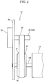
- FIG. 2 is a side view showing the drive force transmission mechanism.
- the drive force transmission mechanism 31 includes a motor 33 as a drive source, a drive pulley 35, a driven pulley 37 and a belt 39 wound around both the drive pulley 35 and the driven pulley 37.
- the motor 33 is fixed to a side plate 3a of the apparatus main body 3.
- An output shaft 33a of the motor 33 is protruded to the inside of the apparatus main body 3 through the side plate 3a.
- the output shaft 33a of the motor 33 serves as the drive pulley 35.
- the drive pulley 35 is made of nonmagnetic material. A diameter of the drive pulley 35 (the output shaft 33a) is 8 mm or larger.
- the drive pulley 35 may be prepared separately from the output shaft 33a, and the prepared drive pulley 35 may be fixed to the output shaft 33a of the motor 33.
- the driven pulley 37 is fixed to an end portion of a rotational shaft 19a of the photosensitive drum 19.
- the driven pulley 37 is made of nonmagnetic material, and has a diameter larger than a diameter of the drive pulley 35 (the output shaft 33a of the motor 33) .
- a protruding part 41 is formed to be protruded outwardly in a radial direction of the driven pulley 37.
- the protruding part 41 has a crown shape in which a center portion in the thickness direction of the driven pulley 37 is protruded more outwardly in the radial direction than end portions in the thickness direction.
- the belt 39 is a seamless endless belt.
- the belt 39 is made of nonmagnetic metal material, such as SUS 304 (austenitic stainless steel) . A manufacturing method of the belt 39 will be described later.
- the belt 39 has a Vickers hardness of 490 Hv or larger, or a tensile strength of 1500 MPa or larger.
- An outer circumferential face of the belt 39 is made to be a mirror face having an average surface roughness Ra of 0.1 ⁇ m or smaller, and an inner circumferential face of the belt 39 has an average surface roughness Ra of 0.3 ⁇ m or smaller.
- the belt 39 is wound around the drive pulley 35 and the driven pulley 37. Because the protruding part 41 is formed around the outer circumferential face of the driven pulley 37, the belt 39 mainly comes into contact with the largest diameter portion of the protruding part 41 when wound around the driven pulley 37.
- an average surface roughness of the outer circumferential face of the belt 39 is smaller than an average surface roughness of the inner circumferential face of the belt 39.
- the outer circumferential face of the belt 39 is a mirror face having an average surface roughness Ra of 0.1 ⁇ m or smaller
- the inner circumferential face of the belt 39 has an average surface roughness Ra of 0.3 ⁇ m or smaller.
- the belt 39 has a Vickers hardness of 490 Hv or larger, it becomes possible to obtain a high rigidity and to prevent a plastic deformation of the belt 39 owing to a load stress at the rotating of the photosensitive drum 19. Therefore, it becomes possible to rotate the photosensitive drum 19 stably for a long period.
- the protruding part 41 is formed around the outer circumferential face of the driven pulley 37, it becomes possible to restrict the belt 39 from being displaced in the thickness direction of the driven pulley 37. That is, the belt 39 mainly comes into contact with the largest diameter portion (the center portion of the outer circumferential face in the thickness direction) of the protruding part 41. Then, a frictional heat is generated between the belt 39 and the largest diameter portion of the protruding part 41, and the largest diameter portion of the protruding part 41 further expands outwardly owing to the generated heat. As a result, a frictional force between the belt 39 and the protruding part 41 is further heightened to prevent the displacement of the belt 39 in the thickness direction of the driven pulley 37.
- the drive pulley 35 may have the same protruding part around the outer circumferential face as that of the driven pulley 37.
- both the pulleys 35 and 37 are made to have the diameter of 8 mm or larger so that it becomes possible to restrict deterioration of a durability of the belt 39.
- a nonmagnetic metal material such as a SUS 304 material
- the metal material is processed into a cylindrical raw pipe.
- the cylindrical raw pipe is subjected to a spinning processing to be plastically deformed to have a thickness of 30 ⁇ m.
- the spinning processing is a processing in which a plurality of rollers is pressed on an outer circumferential face of the raw pipe while rotating the raw pipe to plastically deform the raw pipe so as to have a uniform thickness.
- step S3 the raw pipe after subjected to the spinning processing is cut into a seamless belt body having a predetermined width.
- the belt body is subjected to a low temperature annealing at a temperature of 420 °C or lower.
- the belt body is cured to have a Vickers hardness of 490 Hv or larger.
- a surface of the belt is changed in color to dark brown.
- the low temperature annealing is performed under a nonoxygen environment, the surface of the belt is not always changed in color to dark brown.
- an outer circumferential face of the annealed belt body is polished using a film to be a mirror face having an average surface roughness Ra of 0.1 ⁇ m or smaller.
- step S6 an inner circumferential face of the annealed belt body is processed to have an average surface roughness Ra of 0.3 ⁇ m or smaller.
- the polishing processing using a film is not always required.
- a horizontal axis of the graph shows a number of repeated folding time (number) of a test piece and a vertical axis shows a surface roughness Rz ( ⁇ m) of the test piece. It is shown that as the number of repeated folding time is increased, the durability becomes better.
- a diamond-shaped plot shows the number of repeated folding times at which a break (a break on an end face of the test piece) is observed on the test piece having the corresponding surface roughness Rz.
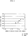
- a horizontal axis of the graph shows a number of repeated folding time (number) of a test piece and a vertical axis shows the tensile strength (MPa) of the test piece.
- a diamond-shaped plot shows the number of repeated folding times at which a break (a break on an end face of the test piece) is not observed on the test piece having the corresponding surface roughness Rz.
- a rectangular plot shows the number of repeated folding times at which a break (a break on an end face of the test piece) is observed on the test piece having the corresponding surface roughness Rz.
- the belt 39 having a Vickers hardness of 490 Hv or larger exhibits a high strength and a high durability. Additionally, the belt 39 having the outer circumferential face formed in a mirror face having an average surface roughness Ra of 0.1 ⁇ m or smaller and the inner circumferential face having an average surface roughness of 0.3 ⁇ m or smaller exhibits a high durability.
Landscapes
- Engineering & Computer Science (AREA)
- General Engineering & Computer Science (AREA)
- Physics & Mathematics (AREA)
- General Physics & Mathematics (AREA)
- Mechanical Engineering (AREA)
- Electrophotography Configuration And Component (AREA)
- Devices For Conveying Motion By Means Of Endless Flexible Members (AREA)
- Discharging, Photosensitive Material Shape In Electrophotography (AREA)
- Pulleys (AREA)
- Shaping Metal By Deep-Drawing, Or The Like (AREA)
Abstract
Description
- The present invention relates to a drive force transmission mechanism which employs a belt to transmit a drive force, an image forming apparatus including the drive force transmission mechanism and a manufacturing method for the belt.
- An image forming apparatus, such as a printer and a copying machine, is provided with a photosensitive drum as an image carrier. The photosensitive drum is configured to be rotated around a rotational shaft to which a rotational force is transmitted from a motor by a drive force transmission mechanism.
- The drive force transmission mechanism is sometimes configured to include a drive pulley fixed to an output shaft of the motor, a driven pully fixed to the rotational shaft of the photosensitive drum and a belt wound around both the pulleys. A rotational force of the drive pulley rotating by the motor is transmitted to the driven pulley through the belt to rotate the photosensitive drum. In many cases, the belt is made of nonmagnetic metal material, such as SUS.
- In the above drive force transmission mechanism, in order to rotate the photosensitive drum stably, the belt requires to have sufficient strength and durability. Various factors of the belt, such as a surface roughness and a rigidity, greatly contribute to the strength and the durability.
- In accordance with an aspect of the present invention, a drive force transmission mechanism includes a drive pulley, a driven pulley and an endless belt. The endless belt is wound around the drive pulley and the driven pulley and transmits a rotation of the drive pulley to the driven pulley. At least one of the drive pulley and the driven pulley has a protruding part protruding outwardly in a radial direction around an outer circumferential face of the drive pulley or the driven pulley. The belt is a nonmagnetic metal belt having an outer circumferential face and an inner circumferential face. The outer circumferential face has a surface roughness smaller than a surface roughness of the inner circumferential face.
- In accordance with an aspect of the present invention, an image forming apparatus includes a photosensitive drum to be rotated by the drive force transmission mechanism.
- In accordance with an aspect of the present invention, a manufacturing method for an endless belt wound around a drive pulley and a driven pulley to transmit a rotation of the drive pulley to the driven pulley includes a step for producing an endless belt body by a spinning processing using a nonmagnetic metal material; a step for low temperature annealing the belt body at a temperature of 420 °C or lower; and a step for film-polishing an outer circumferential face of the low temperature annealed belt body to have an average surface roughness Ra of 0.1 µm or smaller.
- The above and other objects, features, and advantages of the present invention will become more apparent from the following description when taken in conjunction with the accompanying drawings in which a preferred embodiment of the present invention is shown by way of illustrative example.
-
-
FIG. 1 is a front view schematically showing an inner structure of an image forming apparatus according to one embodiment of the present invention. -
FIG. 2 is a side view showing a drive force transmission mechanism according to the embodiment of the present invention. -
FIG. 3 is a flowchart showing a belt manufacturing method according to the embodiment of the present invention. -
FIG. 4 is a graph showing a relationship between a surface roughness and a number of repeated folding times. -
FIG. 5 is a graph showing a relationship between a tensile strength and a number of repeated folding times. - Hereinafter, an image forming apparatus and a drive force transmission mechanism according to an embodiment of the present invention will be described with reference to the drawings.
- Firstly, with reference to
FIG. 1 , an entire structure of the image forming apparatus will be described.FIG. 1 is a front view schematically showing an inner structure of theimage forming apparatus 1. In the following description, a near side (a front side) of a paper surface ofFIG. 1 is defined to be a front side of theimage forming apparatus 1, and a left-and-right direction is defined based on a direction in which theimage forming apparatus 1 is viewed from the front side. In each figure, L and R respectively show a left side and a right side of theimage forming apparatus 1. - An apparatus
main body 3 of theimage forming apparatus 1 is provided with asheet feeding cassette 5 in which a sheet S is stored, a sheet feeding device 7 which feeds the sheet S from thesheet feeding cassette 5, animage forming part 9 which forms a toner image on the sheet S, afixing device 11 which fixes the toner image on the sheet S, asheet discharge device 13 which discharges the sheet S and an discharge tray 15 on which the discharged sheet S is stacked. In the apparatusmain body 3, aconveyance path 17 for the sheet S is formed from the sheet feeding device 7 through theimage forming part 9 and thefixing device 11 to thesheet discharge device 13. - The
image forming part 9 includes aphotosensitive drum 19, acharge device 21, anexposure device 23, adevelopment device 25, atransfer roller 27 and acleaning device 29. Thephotosensitive drum 19 is driven by a drive force transmission mechanism 31 (refer toFIG. 2 ), described later, to be rotated in the clockwise direction inFIG. 1 . Thecharge device 21, thedevelopment device 25, thetransfer roller 27 and thecleaning device 29 are disposed around thephotosensitive drum 19 in the order in the rotational direction of thephotosensitive drum 19. - The sheet S fed by the sheet feeding device 7 from the
sheet feeding cassette 5 is conveyed to theimage forming part 9 along theconveyance path 17. In theimage forming part 9, thephotosensitive drum 19 is firstly charged to a predetermined surface potential while driven by the driveforce transmission mechanism 31 to be rotated. Then, thephotosensitive drum 19 is exposed with theexposure device 23, and an electrostatic latent image is formed on thephotosensitive drum 19. Next, the electrostatic latent image is developed to a toner image by thedevelopment device 25. Then, the toner image is transferred on the conveyed sheet S by thetransfer roller 27. The sheet S to which the toner image is transferred is conveyed along theconveyance path 17 to thefixing device 11. Thefixing device 11 fixes the toner image to the sheet S. The sheet S to which the toner image is fixed is discharged by thedischarge device 13 and then stacked on thedischarge tray 15. The toner remaining on the surface of thephotosensitive drum 19 is removed by thecleaning device 29. - Next, with reference to
FIG. 2 , the driveforce transmission mechanism 31 will be described.FIG. 2 is a side view showing the drive force transmission mechanism. - The drive
force transmission mechanism 31 includes amotor 33 as a drive source, adrive pulley 35, a drivenpulley 37 and abelt 39 wound around both thedrive pulley 35 and the drivenpulley 37. - The
motor 33 is fixed to aside plate 3a of the apparatusmain body 3. Anoutput shaft 33a of themotor 33 is protruded to the inside of the apparatusmain body 3 through theside plate 3a. - In the present embodiment, the
output shaft 33a of themotor 33 serves as thedrive pulley 35. Thedrive pulley 35 is made of nonmagnetic material. A diameter of the drive pulley 35 (theoutput shaft 33a) is 8 mm or larger. Alternatively, thedrive pulley 35 may be prepared separately from theoutput shaft 33a, and the prepareddrive pulley 35 may be fixed to theoutput shaft 33a of themotor 33. - The driven
pulley 37 is fixed to an end portion of arotational shaft 19a of thephotosensitive drum 19. The drivenpulley 37 is made of nonmagnetic material, and has a diameter larger than a diameter of the drive pulley 35 (theoutput shaft 33a of the motor 33) . Around an outer circumferential face of the drivenpulley 37, aprotruding part 41 is formed to be protruded outwardly in a radial direction of the drivenpulley 37. Theprotruding part 41 has a crown shape in which a center portion in the thickness direction of the drivenpulley 37 is protruded more outwardly in the radial direction than end portions in the thickness direction. - The
belt 39 is a seamless endless belt. Thebelt 39 is made of nonmagnetic metal material, such as SUS 304 (austenitic stainless steel) . A manufacturing method of thebelt 39 will be described later. Thebelt 39 has a Vickers hardness of 490 Hv or larger, or a tensile strength of 1500 MPa or larger. An outer circumferential face of thebelt 39 is made to be a mirror face having an average surface roughness Ra of 0.1 µm or smaller, and an inner circumferential face of thebelt 39 has an average surface roughness Ra of 0.3 µm or smaller. - The
belt 39 is wound around thedrive pulley 35 and the drivenpulley 37. Because theprotruding part 41 is formed around the outer circumferential face of the drivenpulley 37, thebelt 39 mainly comes into contact with the largest diameter portion of theprotruding part 41 when wound around the drivenpulley 37. - In the drive
force transmission mechanism 31 having the above described configuration, when themotor 33 is rotated, thedrive pulley 35 is rotated to rotate the drivenpulley 37 through thebelt 39. Then, therotational shaft 19a to which the drivenpulley 37 is fixed is rotated to rotate thephotosensitive drum 19. - As described above, according to the drive
force transmission mechanism 31 of the present invention, an average surface roughness of the outer circumferential face of thebelt 39 is smaller than an average surface roughness of the inner circumferential face of thebelt 39. Specifically, the outer circumferential face of thebelt 39 is a mirror face having an average surface roughness Ra of 0.1 µm or smaller, and the inner circumferential face of thebelt 39 has an average surface roughness Ra of 0.3 µm or smaller. Thereby, when thebelt 39 is wound around both thepulleys belt 39 is easily curled. Accordingly, it becomes possible to travel thebelt 39 stably. Additionally, because thebelt 39 has a Vickers hardness of 490 Hv or larger, it becomes possible to obtain a high rigidity and to prevent a plastic deformation of thebelt 39 owing to a load stress at the rotating of thephotosensitive drum 19. Therefore, it becomes possible to rotate thephotosensitive drum 19 stably for a long period. - Additionally, because the protruding
part 41 is formed around the outer circumferential face of the drivenpulley 37, it becomes possible to restrict thebelt 39 from being displaced in the thickness direction of the drivenpulley 37. That is, thebelt 39 mainly comes into contact with the largest diameter portion (the center portion of the outer circumferential face in the thickness direction) of the protrudingpart 41. Then, a frictional heat is generated between thebelt 39 and the largest diameter portion of the protrudingpart 41, and the largest diameter portion of the protrudingpart 41 further expands outwardly owing to the generated heat. As a result, a frictional force between thebelt 39 and the protrudingpart 41 is further heightened to prevent the displacement of thebelt 39 in the thickness direction of the drivenpulley 37. Thedrive pulley 35 may have the same protruding part around the outer circumferential face as that of the drivenpulley 37. - Additionally, as the diameter of the pulley is small, a tensile strength becomes large and a durability of the belt becomes poor. Then, both the
pulleys belt 39. - Next, a manufacturing method of the
belt 39 will be described with reference to the flowchart shown inFIG. 3 . - Firstly, at step S1, a nonmagnetic metal material, such as a SUS 304 material, is prepared, and the metal material is processed into a cylindrical raw pipe. Next, at step S2, the cylindrical raw pipe is subjected to a spinning processing to be plastically deformed to have a thickness of 30 µm. The spinning processing is a processing in which a plurality of rollers is pressed on an outer circumferential face of the raw pipe while rotating the raw pipe to plastically deform the raw pipe so as to have a uniform thickness.
- Then, at step S3, the raw pipe after subjected to the spinning processing is cut into a seamless belt body having a predetermined width.
- Next, at step S4, the belt body is subjected to a low temperature annealing at a temperature of 420 °C or lower. By the low temperature annealing, the belt body is cured to have a Vickers hardness of 490 Hv or larger. Conventionally, by the low temperature annealing, a surface of the belt is changed in color to dark brown. However, if the low temperature annealing is performed under a nonoxygen environment, the surface of the belt is not always changed in color to dark brown.
- Next, at step S5, an outer circumferential face of the annealed belt body is polished using a film to be a mirror face having an average surface roughness Ra of 0.1 µm or smaller.
- Then, at step S6, an inner circumferential face of the annealed belt body is processed to have an average surface roughness Ra of 0.3 µm or smaller. In this case, the polishing processing using a film is not always required.
- Next, a relationship between a surface roughness and a durability, and a relationship between a rigidity and a durability will be described based on an experimental result. Because it is conventionally known that the rigidity and a tensile strength have a correlation, a relationship between a surface roughness and a durability, and a relationship between a tensile strength and a durability will be described with reference to graphs shown in
FIG. 4 andFIG. 5 . - Firstly, with reference to the graph shown in
FIG. 4 , a relationship between a surface roughness and a durability will be described. A horizontal axis of the graph shows a number of repeated folding time (number) of a test piece and a vertical axis shows a surface roughness Rz (µm) of the test piece. It is shown that as the number of repeated folding time is increased, the durability becomes better. A diamond-shaped plot shows the number of repeated folding times at which a break (a break on an end face of the test piece) is observed on the test piece having the corresponding surface roughness Rz. - As understood by the graph shown in
FIG. 4 , as the surface roughness Rz is small, the number of repeated folding times becomes larger. That is, it is understood that as the surface roughness Rz is small, the durability becomes better. - Next, with reference to the graph shown in
FIG. 5 , a relationship between a tensile strength and a durability will be described. A horizontal axis of the graph shows a number of repeated folding time (number) of a test piece and a vertical axis shows the tensile strength (MPa) of the test piece. A diamond-shaped plot shows the number of repeated folding times at which a break (a break on an end face of the test piece) is not observed on the test piece having the corresponding surface roughness Rz. A rectangular plot shows the number of repeated folding times at which a break (a break on an end face of the test piece) is observed on the test piece having the corresponding surface roughness Rz. - As shown in
FIG. 5 , it is understood that in a case where the tensile strength is high, even if the number of repeated folding times is increased, the break is not observed. That is, it is understood that as the rigidity becomes higher, the durability becomes better. Especially, a tensile strength larger than 1500 MPa shows a good durability. - The above experimental result shows that the
belt 39 having a Vickers hardness of 490 Hv or larger, like the present embodiment, exhibits a high strength and a high durability. Additionally, thebelt 39 having the outer circumferential face formed in a mirror face having an average surface roughness Ra of 0.1 µm or smaller and the inner circumferential face having an average surface roughness of 0.3 µm or smaller exhibits a high durability.
Claims (10)
- A drive force transmission mechanism (31) comprising:a drive pulley (35);a driven pulley (37); andan endless belt (39) wound around the drive pulley (35) and the driven pulley (37) and transmitting a rotation of the drive pulley (35) to the driven pulley (37),wherein at least one of the drive pulley (35) and the driven pulley (37) has a protruding part (41) protruding outwardly in a radial direction around an outer circumferential face of the drive pulley (35) or the driven pulley (37), andthe belt (39) is a nonmagnetic metal belt having an outer circumferential face and an inner circumferential face, the outer circumferential face having a surface roughness smaller than a surface roughness of the inner circumferential face.
- The drive force transmission mechanism (31) according to claim 1,
wherein the outer circumferential face of the belt (39) is a mirror face having an average surface roughness Ra of 0.1 µm or smaller - The drive force transmission mechanism (31) according to claim 1 or claim 2,
wherein the inner circumferential face of the belt (39) has an average surface roughness Ra of 0.3 µm or smaller. - The drive force transmission mechanism (31) according to any one of claims 1 to 3,
wherein the belt (39) has a Vickers hardness of 490 Hv or larger. - The drive force transmission mechanism (31) according to any one of claims 1 to 3,
wherein the belt (39) has a tensile strength of 1500 MPa or larger. - The drive force transmission mechanism (31) according to any one of claims 1 to 5,
wherein the drive pulley (35) or the driven pulley (37) has a diameter of 8 mm or larger. - The drive force transmission mechanism (31) according to any one of claims 1 to 6,
wherein the driven pulley (37) has a diameter larger than a diameter of the drive pulley (35), and
the protruding part (41) is formed around the outer circumferential face of the driven pulley (37). - The drive force transmission mechanism (31) according to any one of claims 1 to 7,
wherein the protruding part (41) has a crown shape where a center portion in a thickness direction of the drive pulley (35) or the driven pulley (37) is protruded more outwardly than end portions in the thickness direction. - An image forming apparatus (1) comprising a photosensitive drum to be rotated by the drive force transmission mechanism according to any one of claims 1 to 8.
- A manufacturing method for an endless belt (39) wound around a drive pulley (35) and a driven pulley (37) to transmit a rotation of the drive pulley (35) to the driven pulley (37), the manufacturing method comprising:a step for producing an endless belt body by a spinning processing using a nonmagnetic metal material;a step for low temperature annealing the belt body at a temperature of 420 °C or lower; anda step for film-polishing an outer circumferential face of the low temperature annealed belt body to have an average surface roughness Ra of 0.1 µm or smaller.
Applications Claiming Priority (1)
| Application Number | Priority Date | Filing Date | Title |
|---|---|---|---|
| JP2018194492A JP7247513B2 (en) | 2018-10-15 | 2018-10-15 | drive transmission device, image forming device |
Publications (2)
| Publication Number | Publication Date |
|---|---|
| EP3647625A1 true EP3647625A1 (en) | 2020-05-06 |
| EP3647625B1 EP3647625B1 (en) | 2021-05-19 |
Family
ID=68109161
Family Applications (1)
| Application Number | Title | Priority Date | Filing Date |
|---|---|---|---|
| EP19200699.7A Active EP3647625B1 (en) | 2018-10-15 | 2019-10-01 | Drive force transmission mechanism, image forming apparatus and belt manufacturing method |
Country Status (4)
| Country | Link |
|---|---|
| US (1) | US11174930B2 (en) |
| EP (1) | EP3647625B1 (en) |
| JP (1) | JP7247513B2 (en) |
| CN (1) | CN111045304A (en) |
Families Citing this family (4)
| Publication number | Priority date | Publication date | Assignee | Title |
|---|---|---|---|---|
| US12395381B2 (en) * | 2022-12-22 | 2025-08-19 | Rakuten Symphony, Inc. | Method, apparatus, and computer readable medium |
| US20240401687A1 (en) * | 2023-01-31 | 2024-12-05 | Belt Technologies, Inc. | Belt Pulley Assembly |
| JP2024169915A (en) | 2023-05-26 | 2024-12-06 | 京セラドキュメントソリューションズ株式会社 | Belt drive mechanism and image forming apparatus |
| JP2025019688A (en) * | 2023-07-28 | 2025-02-07 | 京セラドキュメントソリューションズ株式会社 | Gear coupling structure, drive device and image forming device |
Citations (6)
| Publication number | Priority date | Publication date | Assignee | Title |
|---|---|---|---|---|
| EP0014014A1 (en) * | 1979-01-30 | 1980-08-06 | Van Doorne's Transmissie B.V. | A composite driving belt, endless metal band for a driving belt and a method of processing such a band |
| US20100209647A1 (en) * | 2009-02-19 | 2010-08-19 | Canon Kabushiki Kaisha | Method of manufacturing a belt member and the belt member |
| US20140235392A1 (en) * | 2013-02-21 | 2014-08-21 | Kyocera Document Solutions Inc. | Belt drive mechanism, belt drive apparatus, and pulley |
| US20150043942A1 (en) * | 2013-08-08 | 2015-02-12 | Kyocera Document Solutions Inc. | Driving device for driving endless metal belt and image forming apparatus |
| US20150233445A1 (en) * | 2013-05-28 | 2015-08-20 | Kyocera Document Solutions Inc. | Metal belt and driving mechanism with same metal belt |
| JP2018123844A (en) * | 2017-01-30 | 2018-08-09 | キヤノン株式会社 | Drive transmission device and image formation device including drive transmission device |
Family Cites Families (14)
| Publication number | Priority date | Publication date | Assignee | Title |
|---|---|---|---|---|
| JP2004029757A (en) * | 2002-05-02 | 2004-01-29 | Fuji Xerox Co Ltd | Endless belt, method of manufacturing the same, and image fixing device using the same |
| JP2007177317A (en) * | 2005-11-30 | 2007-07-12 | Jfe Steel Kk | Steel for machine structure excellent in strength, ductility, toughness and wear resistance, method for producing the same, and metal belt using the same |
| JP2010000578A (en) * | 2008-06-20 | 2010-01-07 | Mitsubishi Rayon Eng Co Ltd | Endless belt, method for manufacturing the same, and belt machine |
| JP5371621B2 (en) * | 2009-08-07 | 2013-12-18 | キヤノン株式会社 | Driving device and image forming apparatus |
| US20110193260A1 (en) * | 2010-02-10 | 2011-08-11 | Fujifilm Corporation | Cellulose acetate film and method for producing it, polarizer and liquid crystal display device |
| JP5827506B2 (en) * | 2010-07-16 | 2015-12-02 | キヤノン株式会社 | Manufacturing method of stainless steel seamless belt |
| AT513014A2 (en) * | 2012-05-31 | 2013-12-15 | Berndorf Band Gmbh | Metal strip and method for producing a surface-polished metal strip |
| JP2014159866A (en) * | 2013-02-21 | 2014-09-04 | Kyocera Document Solutions Inc | Belt drive mechanism and belt drive device |
| JP2014159867A (en) * | 2013-02-21 | 2014-09-04 | Kyocera Document Solutions Inc | Belt drive mechanism, belt drive device, and pulley |
| NL1041120B1 (en) * | 2014-12-23 | 2016-10-11 | Bosch Gmbh Robert | An endless metal band with a coated surface, a drive belt provided with the endless metal band and method for shaping the drive belt. |
| EP3059024B1 (en) * | 2015-02-17 | 2023-07-19 | K.K. Endo Seisakusho | Fixing sleeve and manufacturing method thereof |
| CN105290725B (en) * | 2015-08-05 | 2018-08-28 | 上海罗特钢带系统股份有限公司 | A method of preparing high-precision annular abrasion minute surface steel band |
| JP2017227844A (en) * | 2016-06-24 | 2017-12-28 | キヤノン株式会社 | Power transmission device and image forming apparatus having the same |
| CN107442880A (en) * | 2017-08-31 | 2017-12-08 | 阜阳扬宇充电设备有限公司 | A kind of adjustable solder machine of power module |
-
2018
- 2018-10-15 JP JP2018194492A patent/JP7247513B2/en active Active
-
2019
- 2019-10-01 EP EP19200699.7A patent/EP3647625B1/en active Active
- 2019-10-04 US US16/593,481 patent/US11174930B2/en active Active
- 2019-10-09 CN CN201910955075.8A patent/CN111045304A/en active Pending
Patent Citations (6)
| Publication number | Priority date | Publication date | Assignee | Title |
|---|---|---|---|---|
| EP0014014A1 (en) * | 1979-01-30 | 1980-08-06 | Van Doorne's Transmissie B.V. | A composite driving belt, endless metal band for a driving belt and a method of processing such a band |
| US20100209647A1 (en) * | 2009-02-19 | 2010-08-19 | Canon Kabushiki Kaisha | Method of manufacturing a belt member and the belt member |
| US20140235392A1 (en) * | 2013-02-21 | 2014-08-21 | Kyocera Document Solutions Inc. | Belt drive mechanism, belt drive apparatus, and pulley |
| US20150233445A1 (en) * | 2013-05-28 | 2015-08-20 | Kyocera Document Solutions Inc. | Metal belt and driving mechanism with same metal belt |
| US20150043942A1 (en) * | 2013-08-08 | 2015-02-12 | Kyocera Document Solutions Inc. | Driving device for driving endless metal belt and image forming apparatus |
| JP2018123844A (en) * | 2017-01-30 | 2018-08-09 | キヤノン株式会社 | Drive transmission device and image formation device including drive transmission device |
Also Published As
| Publication number | Publication date |
|---|---|
| EP3647625B1 (en) | 2021-05-19 |
| US11174930B2 (en) | 2021-11-16 |
| CN111045304A (en) | 2020-04-21 |
| JP2020064111A (en) | 2020-04-23 |
| US20200116248A1 (en) | 2020-04-16 |
| JP7247513B2 (en) | 2023-03-29 |
Similar Documents
| Publication | Publication Date | Title |
|---|---|---|
| EP3647625B1 (en) | Drive force transmission mechanism, image forming apparatus and belt manufacturing method | |
| US9423002B2 (en) | Metal belt and driving mechanism with same metal belt | |
| JP2019163800A (en) | Driving transmission device and image forming device | |
| EP3722884A1 (en) | Image forming apparatus | |
| US20200063851A1 (en) | Drive transmission device and image forming apparatus incorporating the drive transmission device | |
| US6898400B2 (en) | Drive apparatus for a rotary member, an image forming apparatus, and a method of assembly for a drive apparatus | |
| US9891551B2 (en) | Roller member, roller supporting mechanism, and image forming apparatus | |
| JP6456024B2 (en) | Roller, cartridge, image forming apparatus, and cylindrical shaft manufacturing method | |
| JP6537229B2 (en) | Drive transmission mechanism and image forming apparatus | |
| US10908549B2 (en) | Drive force transmission mechanism and image forming apparatus | |
| JP6376759B2 (en) | Sheet discharging apparatus and image forming apparatus | |
| CN110018627B (en) | Driving force transmission mechanism and image forming apparatus | |
| JP5568520B2 (en) | Photosensitive drum and image forming apparatus having the same | |
| JP6039438B2 (en) | Sheet feeding apparatus and image forming apparatus | |
| USRE48099E1 (en) | Fuser using endless belt and image forming apparatus | |
| JP2005043593A (en) | Image forming apparatus | |
| US20250304388A1 (en) | Medium conveyance device and image forming apparatus | |
| JP2019074119A (en) | One-way clutch and image formation device | |
| JP2001265165A (en) | Image forming apparatus and driving force transmission device | |
| JP4963623B2 (en) | Image forming apparatus | |
| JP2002304031A (en) | Driving unit of image forming apparatus and image forming apparatus including the same | |
| JPH0635362A (en) | Fixing device | |
| JP2019074118A (en) | One-way clutch and image formation device | |
| JP2005173352A (en) | Image forming apparatus |
Legal Events
| Date | Code | Title | Description |
|---|---|---|---|
| PUAI | Public reference made under article 153(3) epc to a published international application that has entered the european phase |
Free format text: ORIGINAL CODE: 0009012 |
|
| STAA | Information on the status of an ep patent application or granted ep patent |
Free format text: STATUS: THE APPLICATION HAS BEEN PUBLISHED |
|
| AK | Designated contracting states |
Kind code of ref document: A1 Designated state(s): AL AT BE BG CH CY CZ DE DK EE ES FI FR GB GR HR HU IE IS IT LI LT LU LV MC MK MT NL NO PL PT RO RS SE SI SK SM TR |
|
| AX | Request for extension of the european patent |
Extension state: BA ME |
|
| STAA | Information on the status of an ep patent application or granted ep patent |
Free format text: STATUS: REQUEST FOR EXAMINATION WAS MADE |
|
| 17P | Request for examination filed |
Effective date: 20201102 |
|
| RBV | Designated contracting states (corrected) |
Designated state(s): AL AT BE BG CH CY CZ DE DK EE ES FI FR GB GR HR HU IE IS IT LI LT LU LV MC MK MT NL NO PL PT RO RS SE SI SK SM TR |
|
| GRAP | Despatch of communication of intention to grant a patent |
Free format text: ORIGINAL CODE: EPIDOSNIGR1 |
|
| STAA | Information on the status of an ep patent application or granted ep patent |
Free format text: STATUS: GRANT OF PATENT IS INTENDED |
|
| INTG | Intention to grant announced |
Effective date: 20201216 |
|
| GRAS | Grant fee paid |
Free format text: ORIGINAL CODE: EPIDOSNIGR3 |
|
| GRAA | (expected) grant |
Free format text: ORIGINAL CODE: 0009210 |
|
| STAA | Information on the status of an ep patent application or granted ep patent |
Free format text: STATUS: THE PATENT HAS BEEN GRANTED |
|
| AK | Designated contracting states |
Kind code of ref document: B1 Designated state(s): AL AT BE BG CH CY CZ DE DK EE ES FI FR GB GR HR HU IE IS IT LI LT LU LV MC MK MT NL NO PL PT RO RS SE SI SK SM TR |
|
| REG | Reference to a national code |
Ref country code: GB Ref legal event code: FG4D |
|
| REG | Reference to a national code |
Ref country code: CH Ref legal event code: EP |
|
| REG | Reference to a national code |
Ref country code: DE Ref legal event code: R096 Ref document number: 602019004708 Country of ref document: DE |
|
| REG | Reference to a national code |
Ref country code: AT Ref legal event code: REF Ref document number: 1394271 Country of ref document: AT Kind code of ref document: T Effective date: 20210615 |
|
| REG | Reference to a national code |
Ref country code: IE Ref legal event code: FG4D |
|
| REG | Reference to a national code |
Ref country code: LT Ref legal event code: MG9D |
|
| REG | Reference to a national code |
Ref country code: AT Ref legal event code: MK05 Ref document number: 1394271 Country of ref document: AT Kind code of ref document: T Effective date: 20210519 |
|
| REG | Reference to a national code |
Ref country code: NL Ref legal event code: MP Effective date: 20210519 |
|
| PG25 | Lapsed in a contracting state [announced via postgrant information from national office to epo] |
Ref country code: FI Free format text: LAPSE BECAUSE OF FAILURE TO SUBMIT A TRANSLATION OF THE DESCRIPTION OR TO PAY THE FEE WITHIN THE PRESCRIBED TIME-LIMIT Effective date: 20210519 Ref country code: HR Free format text: LAPSE BECAUSE OF FAILURE TO SUBMIT A TRANSLATION OF THE DESCRIPTION OR TO PAY THE FEE WITHIN THE PRESCRIBED TIME-LIMIT Effective date: 20210519 Ref country code: LT Free format text: LAPSE BECAUSE OF FAILURE TO SUBMIT A TRANSLATION OF THE DESCRIPTION OR TO PAY THE FEE WITHIN THE PRESCRIBED TIME-LIMIT Effective date: 20210519 Ref country code: BG Free format text: LAPSE BECAUSE OF FAILURE TO SUBMIT A TRANSLATION OF THE DESCRIPTION OR TO PAY THE FEE WITHIN THE PRESCRIBED TIME-LIMIT Effective date: 20210819 Ref country code: AT Free format text: LAPSE BECAUSE OF FAILURE TO SUBMIT A TRANSLATION OF THE DESCRIPTION OR TO PAY THE FEE WITHIN THE PRESCRIBED TIME-LIMIT Effective date: 20210519 |
|
| PG25 | Lapsed in a contracting state [announced via postgrant information from national office to epo] |
Ref country code: GR Free format text: LAPSE BECAUSE OF FAILURE TO SUBMIT A TRANSLATION OF THE DESCRIPTION OR TO PAY THE FEE WITHIN THE PRESCRIBED TIME-LIMIT Effective date: 20210820 Ref country code: IS Free format text: LAPSE BECAUSE OF FAILURE TO SUBMIT A TRANSLATION OF THE DESCRIPTION OR TO PAY THE FEE WITHIN THE PRESCRIBED TIME-LIMIT Effective date: 20210919 Ref country code: NO Free format text: LAPSE BECAUSE OF FAILURE TO SUBMIT A TRANSLATION OF THE DESCRIPTION OR TO PAY THE FEE WITHIN THE PRESCRIBED TIME-LIMIT Effective date: 20210819 Ref country code: LV Free format text: LAPSE BECAUSE OF FAILURE TO SUBMIT A TRANSLATION OF THE DESCRIPTION OR TO PAY THE FEE WITHIN THE PRESCRIBED TIME-LIMIT Effective date: 20210519 Ref country code: PL Free format text: LAPSE BECAUSE OF FAILURE TO SUBMIT A TRANSLATION OF THE DESCRIPTION OR TO PAY THE FEE WITHIN THE PRESCRIBED TIME-LIMIT Effective date: 20210519 Ref country code: SE Free format text: LAPSE BECAUSE OF FAILURE TO SUBMIT A TRANSLATION OF THE DESCRIPTION OR TO PAY THE FEE WITHIN THE PRESCRIBED TIME-LIMIT Effective date: 20210519 Ref country code: RS Free format text: LAPSE BECAUSE OF FAILURE TO SUBMIT A TRANSLATION OF THE DESCRIPTION OR TO PAY THE FEE WITHIN THE PRESCRIBED TIME-LIMIT Effective date: 20210519 Ref country code: PT Free format text: LAPSE BECAUSE OF FAILURE TO SUBMIT A TRANSLATION OF THE DESCRIPTION OR TO PAY THE FEE WITHIN THE PRESCRIBED TIME-LIMIT Effective date: 20210920 |
|
| PG25 | Lapsed in a contracting state [announced via postgrant information from national office to epo] |
Ref country code: NL Free format text: LAPSE BECAUSE OF FAILURE TO SUBMIT A TRANSLATION OF THE DESCRIPTION OR TO PAY THE FEE WITHIN THE PRESCRIBED TIME-LIMIT Effective date: 20210519 |
|
| PG25 | Lapsed in a contracting state [announced via postgrant information from national office to epo] |
Ref country code: ES Free format text: LAPSE BECAUSE OF FAILURE TO SUBMIT A TRANSLATION OF THE DESCRIPTION OR TO PAY THE FEE WITHIN THE PRESCRIBED TIME-LIMIT Effective date: 20210519 Ref country code: EE Free format text: LAPSE BECAUSE OF FAILURE TO SUBMIT A TRANSLATION OF THE DESCRIPTION OR TO PAY THE FEE WITHIN THE PRESCRIBED TIME-LIMIT Effective date: 20210519 Ref country code: SK Free format text: LAPSE BECAUSE OF FAILURE TO SUBMIT A TRANSLATION OF THE DESCRIPTION OR TO PAY THE FEE WITHIN THE PRESCRIBED TIME-LIMIT Effective date: 20210519 Ref country code: DK Free format text: LAPSE BECAUSE OF FAILURE TO SUBMIT A TRANSLATION OF THE DESCRIPTION OR TO PAY THE FEE WITHIN THE PRESCRIBED TIME-LIMIT Effective date: 20210519 Ref country code: CZ Free format text: LAPSE BECAUSE OF FAILURE TO SUBMIT A TRANSLATION OF THE DESCRIPTION OR TO PAY THE FEE WITHIN THE PRESCRIBED TIME-LIMIT Effective date: 20210519 Ref country code: RO Free format text: LAPSE BECAUSE OF FAILURE TO SUBMIT A TRANSLATION OF THE DESCRIPTION OR TO PAY THE FEE WITHIN THE PRESCRIBED TIME-LIMIT Effective date: 20210519 Ref country code: SM Free format text: LAPSE BECAUSE OF FAILURE TO SUBMIT A TRANSLATION OF THE DESCRIPTION OR TO PAY THE FEE WITHIN THE PRESCRIBED TIME-LIMIT Effective date: 20210519 |
|
| REG | Reference to a national code |
Ref country code: DE Ref legal event code: R097 Ref document number: 602019004708 Country of ref document: DE |
|
| PLBE | No opposition filed within time limit |
Free format text: ORIGINAL CODE: 0009261 |
|
| STAA | Information on the status of an ep patent application or granted ep patent |
Free format text: STATUS: NO OPPOSITION FILED WITHIN TIME LIMIT |
|
| 26N | No opposition filed |
Effective date: 20220222 |
|
| PG25 | Lapsed in a contracting state [announced via postgrant information from national office to epo] |
Ref country code: IS Free format text: LAPSE BECAUSE OF FAILURE TO SUBMIT A TRANSLATION OF THE DESCRIPTION OR TO PAY THE FEE WITHIN THE PRESCRIBED TIME-LIMIT Effective date: 20210919 Ref country code: AL Free format text: LAPSE BECAUSE OF FAILURE TO SUBMIT A TRANSLATION OF THE DESCRIPTION OR TO PAY THE FEE WITHIN THE PRESCRIBED TIME-LIMIT Effective date: 20210519 |
|
| REG | Reference to a national code |
Ref country code: BE Ref legal event code: MM Effective date: 20211031 |
|
| PG25 | Lapsed in a contracting state [announced via postgrant information from national office to epo] |
Ref country code: MC Free format text: LAPSE BECAUSE OF FAILURE TO SUBMIT A TRANSLATION OF THE DESCRIPTION OR TO PAY THE FEE WITHIN THE PRESCRIBED TIME-LIMIT Effective date: 20210519 |
|
| PG25 | Lapsed in a contracting state [announced via postgrant information from national office to epo] |
Ref country code: LU Free format text: LAPSE BECAUSE OF NON-PAYMENT OF DUE FEES Effective date: 20211001 Ref country code: IT Free format text: LAPSE BECAUSE OF FAILURE TO SUBMIT A TRANSLATION OF THE DESCRIPTION OR TO PAY THE FEE WITHIN THE PRESCRIBED TIME-LIMIT Effective date: 20210519 Ref country code: BE Free format text: LAPSE BECAUSE OF NON-PAYMENT OF DUE FEES Effective date: 20211031 |
|
| PG25 | Lapsed in a contracting state [announced via postgrant information from national office to epo] |
Ref country code: IE Free format text: LAPSE BECAUSE OF NON-PAYMENT OF DUE FEES Effective date: 20211001 |
|
| REG | Reference to a national code |
Ref country code: CH Ref legal event code: PL |
|
| P01 | Opt-out of the competence of the unified patent court (upc) registered |
Effective date: 20230420 |
|
| PG25 | Lapsed in a contracting state [announced via postgrant information from national office to epo] |
Ref country code: CY Free format text: LAPSE BECAUSE OF FAILURE TO SUBMIT A TRANSLATION OF THE DESCRIPTION OR TO PAY THE FEE WITHIN THE PRESCRIBED TIME-LIMIT Effective date: 20210519 |
|
| PG25 | Lapsed in a contracting state [announced via postgrant information from national office to epo] |
Ref country code: LI Free format text: LAPSE BECAUSE OF NON-PAYMENT OF DUE FEES Effective date: 20221031 Ref country code: HU Free format text: LAPSE BECAUSE OF FAILURE TO SUBMIT A TRANSLATION OF THE DESCRIPTION OR TO PAY THE FEE WITHIN THE PRESCRIBED TIME-LIMIT; INVALID AB INITIO Effective date: 20191001 Ref country code: CH Free format text: LAPSE BECAUSE OF NON-PAYMENT OF DUE FEES Effective date: 20221031 |
|
| PG25 | Lapsed in a contracting state [announced via postgrant information from national office to epo] |
Ref country code: MK Free format text: LAPSE BECAUSE OF FAILURE TO SUBMIT A TRANSLATION OF THE DESCRIPTION OR TO PAY THE FEE WITHIN THE PRESCRIBED TIME-LIMIT Effective date: 20210519 |
|
| PG25 | Lapsed in a contracting state [announced via postgrant information from national office to epo] |
Ref country code: TR Free format text: LAPSE BECAUSE OF FAILURE TO SUBMIT A TRANSLATION OF THE DESCRIPTION OR TO PAY THE FEE WITHIN THE PRESCRIBED TIME-LIMIT Effective date: 20210519 |
|
| PG25 | Lapsed in a contracting state [announced via postgrant information from national office to epo] |
Ref country code: MT Free format text: LAPSE BECAUSE OF FAILURE TO SUBMIT A TRANSLATION OF THE DESCRIPTION OR TO PAY THE FEE WITHIN THE PRESCRIBED TIME-LIMIT Effective date: 20210519 |
|
| PGFP | Annual fee paid to national office [announced via postgrant information from national office to epo] |
Ref country code: GB Payment date: 20250923 Year of fee payment: 7 |
|
| PGFP | Annual fee paid to national office [announced via postgrant information from national office to epo] |
Ref country code: FR Payment date: 20250924 Year of fee payment: 7 |
|
| PGFP | Annual fee paid to national office [announced via postgrant information from national office to epo] |
Ref country code: DE Payment date: 20250923 Year of fee payment: 7 |