EP3647600A1 - Identification d'un périphérique connecté électriquement - Google Patents
Identification d'un périphérique connecté électriquement Download PDFInfo
- Publication number
- EP3647600A1 EP3647600A1 EP19201918.0A EP19201918A EP3647600A1 EP 3647600 A1 EP3647600 A1 EP 3647600A1 EP 19201918 A EP19201918 A EP 19201918A EP 3647600 A1 EP3647600 A1 EP 3647600A1
- Authority
- EP
- European Patent Office
- Prior art keywords
- connection
- accessory unit
- vacuum device
- accessory
- message
- Prior art date
- Legal status (The legal status is an assumption and is not a legal conclusion. Google has not performed a legal analysis and makes no representation as to the accuracy of the status listed.)
- Granted
Links
- 230000002093 peripheral effect Effects 0.000 title 1
- 238000004891 communication Methods 0.000 claims abstract description 82
- 230000004044 response Effects 0.000 claims abstract description 39
- 238000000034 method Methods 0.000 claims abstract description 31
- 238000010438 heat treatment Methods 0.000 claims description 7
- 238000007789 sealing Methods 0.000 claims description 7
- 238000001816 cooling Methods 0.000 claims description 6
- 238000005259 measurement Methods 0.000 claims description 5
- XLYOFNOQVPJJNP-UHFFFAOYSA-N water Substances O XLYOFNOQVPJJNP-UHFFFAOYSA-N 0.000 claims description 4
- 230000005540 biological transmission Effects 0.000 claims description 2
- 238000001514 detection method Methods 0.000 description 19
- 238000010586 diagram Methods 0.000 description 10
- 238000011161 development Methods 0.000 description 4
- 230000001419 dependent effect Effects 0.000 description 3
- 238000005516 engineering process Methods 0.000 description 3
- 230000008569 process Effects 0.000 description 3
- 238000012545 processing Methods 0.000 description 3
- 230000008859 change Effects 0.000 description 2
- 230000008901 benefit Effects 0.000 description 1
- 238000010276 construction Methods 0.000 description 1
- 125000004122 cyclic group Chemical group 0.000 description 1
- 238000009434 installation Methods 0.000 description 1
- 238000012423 maintenance Methods 0.000 description 1
- 238000012986 modification Methods 0.000 description 1
- 230000004048 modification Effects 0.000 description 1
- 238000004886 process control Methods 0.000 description 1
- 230000011664 signaling Effects 0.000 description 1
- 238000012549 training Methods 0.000 description 1
Images


Classifications
-
- F—MECHANICAL ENGINEERING; LIGHTING; HEATING; WEAPONS; BLASTING
- F04—POSITIVE - DISPLACEMENT MACHINES FOR LIQUIDS; PUMPS FOR LIQUIDS OR ELASTIC FLUIDS
- F04D—NON-POSITIVE-DISPLACEMENT PUMPS
- F04D19/00—Axial-flow pumps
- F04D19/02—Multi-stage pumps
- F04D19/04—Multi-stage pumps specially adapted to the production of a high vacuum, e.g. molecular pumps
-
- F—MECHANICAL ENGINEERING; LIGHTING; HEATING; WEAPONS; BLASTING
- F04—POSITIVE - DISPLACEMENT MACHINES FOR LIQUIDS; PUMPS FOR LIQUIDS OR ELASTIC FLUIDS
- F04D—NON-POSITIVE-DISPLACEMENT PUMPS
- F04D27/00—Control, e.g. regulation, of pumps, pumping installations or pumping systems specially adapted for elastic fluids
- F04D27/001—Testing thereof; Determination or simulation of flow characteristics; Stall or surge detection, e.g. condition monitoring
Definitions
- the present invention relates to a method for operating a vacuum device, in particular a vacuum pump system, the vacuum device having a control unit with a connection for an accessory unit.
- the invention also relates to a vacuum device, in particular a vacuum pump system, with a control unit for operating the vacuum device.
- the vacuum device can also be a vacuum device other than a vacuum pump system.
- the vacuum device can be a display device or a pressure measuring device.
- one or more connections are each provided for an accessory unit.
- the accessory unit is operated by a control unit of the vacuum device.
- the vacuum device can contain an input device on which a user can identify the connected accessory unit.
- entering the information manually is tedious and not very flexible.
- a method for operating a vacuum device in particular a vacuum pump system or a display device or a pressure measuring device, the vacuum device having a control unit with a connection for an accessory unit, with the features of claim 1, and in particular in that the method at least comprises the following steps: outputting a message via the connection in accordance with a predetermined communication protocol; Determining whether a response to the message is received over the port; if it is determined that a response to the message is not received, determining whether an electrical resistor is connected to the connector (in other words connected to the connector); and if it is determined that an electrical resistance is connected to the connection, recognizing and / or actuating the accessory unit based on the connected electrical resistance.
- determining whether an electrical resistor is connected to the connection means that it is determined whether an (external) resistor (for example a characteristic resistor in the accessory unit) is connected to the connection (for example via a plug connection on the Connection to which an accessory unit can be connected).
- an electrical resistance for example a characteristic resistor in the accessory unit
- an attempt is made to determine whether an accessory unit is connected to certain connecting lines of a vacuum device, which can communicate with the vacuum device in accordance with a predetermined communication protocol and can thus actively identify itself with the vacuum device, and if it is found that such an accessory unit is not is connected, an attempt is made to determine whether an accessory unit, which can be identified by ascertaining a characteristic resistor installed in the accessory unit, is connected to the specific connecting lines of the vacuum device.
- connection of the accessory unit can be carried out in a particularly simple manner, in particular without a manual or other external configuration, or with a manual or other external configuration adapted to the accessory unit.
- This also makes the operation of the vacuum device particularly flexible, since accessory units can be connected, disconnected and / or replaced without great effort and as required.
- a particularly comfortable operation in the sense of a "plug and play" concept is realized.
- a connected accessory unit advantageously gains its function simply by connecting to the connection.
- Accessories that can communicate with the vacuum device according to the specified communication protocol can also be referred to as “active accessories” or “intelligent accessories” because they can actively communicate with the vacuum device and can thus actively identify themselves with the vacuum device.
- Accessory units that cannot communicate with the vacuum device in accordance with the specified communication protocol can also be referred to as "passive accessory units" because they cannot actively identify themselves with the vacuum device, but rather by determining an electrical one Resistance can be recognized by the vacuum device.
- Passive accessories can preferably only be switched on and off, such as valves, fans or relays.
- the specified communication protocol can be a digital communication protocol.
- the predetermined communication protocol can be set up to transmit digital information.
- the message can be digital information converted into a voltage sequence according to the predetermined communication protocol (in other words: a sequence of logical values, for example a sequence of bits, for example a sequence of logical values 0 and 1).
- a resistor is connected to the connection or not, and / or the value of the resistor can be determined.
- a two-step method is used in which it is first determined whether a resistor is connected to the connection and then, if it is determined that a resistor is connected to the connection, the value of the resistance is determined.
- control unit can operate and / or control it as required.
- control unit can recognize the accessory unit on the basis of a label and call up further information, such as maximum tolerable voltage, from a stored table.
- control unit immediately recognizes the necessary information, in particular on the basis of a signal emitted by the accessory unit in the case of an active accessory unit.
- the connection can have a plurality of communication contacts (in other words: pins; in other words: lines) for communicatively connecting the accessory unit to the control unit.
- the communication contacts can be metallic and / or electrical contacts.
- at least one communication contact is used both for communication in accordance with the predetermined communication protocol (that is to say outputting the message via the connection and / or receiving a response or determining whether a message was received) and also determining whether there is a resistance to the connection connected.
- a pin of the connection can be used either in accordance with the specified communication protocol or as a measuring line for an analog value (for example a voltage which is dependent on the resistance).
- the type of function of the pin (according to the communication protocol or as a measuring line) can be determined, for example, by a microcontroller that is also used to operate the Communication protocol is used, determined and / or carried out.
- the possibility of communication between the control unit and the active accessory unit can not only simplify the detection, but also make the operation considerably more flexible, since data can now be exchanged between the control unit and the accessory unit.
- communication in both directions is possible.
- the communication contact can also be used for communication with other units that are not accessory units, that is, for example, for communication with a configuration and / or diagnostic unit, a further vacuum device and / or a process control system.
- a separate interface such as a diagnostic or configuration interface, can then advantageously be dispensed with.
- several communication contacts, in particular per connection can also be provided.
- the same interface can be used to recognize and / or control the passive accessory unit.
- the following steps can be carried out: outputting a further message via the connection in accordance with the predetermined communication protocol; Determining whether a response to the further message is received via the connection; if it is determined that a response to the further message is received, actuating the accessory unit based on the received message. If no active accessory unit is connected at first, and it is then determined that no passive accessory unit is connected, the detection of the active accessory unit is reduced.
- a message can be output cyclically via the connection in accordance with the predetermined communication protocol and it can be determined whether an electrical resistance is connected to the connection until either a response to the message is received or it is determined that an electrical resistance is present the connection is connected. It is therefore possible to switch between the detection of active accessory units and passive accessory unit until an accessory unit (active or passive) is identified. The accessory unit can then be recognized and / or controlled based on the response received (for an active accessory unit) or the connected electrical resistance (for a passive accessory unit).
- the change between the detection of active accessory units and the detection of passive accessory units can be terminated according to a predetermined rule (for example after a predetermined time has elapsed or after a predetermined number of (unsuccessful) recognition attempts) and a warning message can be issued to the user, for example will.
- a predetermined rule for example after a predetermined time has elapsed or after a predetermined number of (unsuccessful) recognition attempts
- determining whether a response to the message is received via the connection can include: determining whether a response to the message was received within the predetermined response time.
- the predefined response time can be selected in accordance with the predefined communication protocol. The response time can in particular be chosen so that it the communication times between the Vacuum device and the accessory unit as well as the processing time in the accessory unit in response to the message received in the accessory unit. For example, the predefined response time can be in the range from 1 ⁇ s to 500 ms.
- an electrical resistance is connected to the connection (in other words if a passive accessory unit is recognized)
- the predetermined time interval can be selected so that on the one hand the effort of the repeated determination is limited, and on the other hand in time (for example in time to ensure safe operation of the vacuum device even without the accessory unit) if a previously connected accessory unit is no longer is connected to the connector.
- the time interval can be in the range from 1 s to 100 s.
- the following steps can be carried out: output of a further message via the connection in accordance with the predetermined communication protocol; Determining whether a response to the further message is received via the connection; if it is determined that a response to the message is received, address the Accessory unit based on the message received. After it is recognized that a previously connected passive accessory unit is no longer connected to the connector, it can recognize an active accessory unit (by outputting a message via the connector in accordance with the specified communication protocol and determining whether a response is received) or one passive accessory unit (by determining whether an electrical resistor is connected to the connector). This makes it possible to determine immediately after removing a previously connected accessory unit whether an accessory unit is connected again.
- the communication protocol can be a serial protocol.
- the serial protocol can be set up according to RS-232 (or ANSI EIA /) TIA-232-F or EIA-232), RS-422 (or EIA-422 or ITU-T V.11), RS-423 ( or EIA-423) or RS-485 (or EIA-485), LVDS (Low Voltage Differential Signaling) or TTY.
- At least one of the communication contacts that are used for the serial interface can be used to determine whether an electrical resistor is connected to this communication contact. This enables serial and analog detection of accessory units on the same connection.
- Serial detection can mean detection of active accessories.
- Analog detection can mean detection of passive accessories.
- the object of the invention is also achieved by a vacuum device, in particular a vacuum pump system, with a control unit for operating the vacuum device according to the independent claim directed thereon, in particular by a control unit for operating the vacuum device, the control unit being adapted to the method for operating the vacuum device Vacuum device to run at least partially.
- connection has a voltage supply line and a serial interface with a receive line and a transmission line. This means that both the control of active accessory units and the voltage supply of both active and passive accessory units can take place.
- a measuring resistor can be arranged between the receive line and the voltage supply line (or any other node in the vacuum device that provides a voltage supply).
- the control unit can be adapted to determine whether an electrical resistance is connected to the connection based on a measurement of a current through the measurement resistance or a voltage (in other words: a voltage drop) at the measurement resistance.
- the resistance in the accessory unit can be determined, for example, via a voltage drop across the measuring resistor.
- the measuring resistor can have an ohmic resistance in the range of several 100 ohms to several kiloohms.
- control unit can have a circuit board as a vacuum feedthrough.
- vacuum feedthrough can also serve as an electronic component.
- the accessory unit can be a sensor, a piezo sensor, a piezo / Pirani sensor, a flood valve, a sealing gas throttle, a sealing gas valve, a heater (for example a water heater or an air heater), a cooling device (for example a water cooling or an air cooling), a relay and a backing pump contain or be.
- accessory units that can only be switched on and off are preferably passive accessory units.
- More complex accessories that require control based on several parameters are preferably active Accessory units in which the controller is already communicating in accordance with the specified communication protocol.
- connection has at least one supply contact for the electrical supply of the accessory unit.
- the accessory unit therefore does not require an additional power connection, which simplifies the arrangement.
- a driver can be provided for the supply contact or for the connection. This can advantageously be designed in such a way that accessory units from older device generations can also be operated reliably, in particular without means for transmitting identification signals (for example passive accessory units).
- the control unit can be designed to supply the accessory unit with different voltages, in particular via the supply contact.
- these are two different voltages, in particular zero and a general operating voltage for all accessories.
- At least two different voltages different from zero are particularly advantageous.
- the connection of accessory units can be made more flexible, since they can be supplied as required without the need for a transformer on the accessory unit.
- the control unit is designed to apply a first non-zero voltage, for example 5 V, in principle, in particular to the connection or to the supply contact, and, after detection and / or communication with the accessory unit, another voltage suitable for the accessory unit Voltage, for example 24 V, to apply.
- a specific supply voltage is permanently present, for example at the supply contact.
- the accessory unit advantageously controls itself, in particular in Dependency on commands or data specified by the control unit, which are advantageously transmitted via a communication contact of the connection. This simplifies the vacuum device and control unit technically.
- the supply contact can be used, for example, both for supplying energy to the accessory unit and as a mere switching means for actuating a switch, such as a relay, for example in the case of a passive accessory unit.
- a switch such as a relay
- accessories can also be operated for which a power supply via the vacuum device would be impossible or technically very complex.
- the accessory unit can be a backing pump for the vacuum device designed here as a vacuum pump. This backing pump requires a relatively large output, which could only be provided with a special technical effort by the vacuum device. On top of this, this leads to an increased installation space, which is often undesirable. In this example, the energy supply to the accessory unit is thus advantageously outsourced.
- a vacuum device Insofar as a vacuum device is described above as a unit different from the accessory unit, this relates to vacuum devices which are not intended as accessories for the vacuum device according to the invention, but are operated in a subordinate manner.
- the backing pump described here is subordinate to the vacuum pump and dependent.
- the backing pump is also controlled via the supply contact. In principle, however, it can also be controlled via a communication contact or other means of communication.
- the connection according to the invention can be designed and used in a variety of ways. Control and / or communication can be implemented for numerous units, in particular starting from the control unit. In all of this, the automatic recognition of the accessory unit according to the invention ensures both Passive accessories as well as active accessories by the control unit for a completely new flexibility and simplicity.
- the supply contact can be used to determine a voltage drop across the measuring resistor in the vacuum device, and thus the resistance in the accessory unit.
- control unit is designed to control the accessory unit as a function of parameters of the vacuum device.
- the speed is controlled as a function of a temperature in or on the vacuum device. This control can take place, on the one hand, via a supply contact and, on the other hand, via a communication contact, in which case the accessory unit is then prompted to adjust the speed itself.
- the vacuum device and / or accessory unit are even designed such that both are possible.
- a common contact can also be provided as a communication contact and supply contact. Communication and supply are then also possible via the same line. This proves to be particularly advantageous in terms of compatibility. Existing connections do not need to be redesigned. In addition, the construction is and remains simple.
- control unit is designed to recognize the type of accessory unit from a signal emanating from the accessory unit.
- the signal can include, for example, an identifier and / or information that directly parameters the Accessories, such as operating voltage, concern.
- the signal can be a message according to the specified communication protocol.
- the signal can be made available, for example, via a communication contact of the connection of the control unit. This enables particularly simple operation.
- a serial interface for the accessory unit can be provided at the connection. This enables particularly reliable communication to be implemented in a simple manner.
- a bus interface for the accessory unit can be provided at the connection. This enables particularly flexible operation for a large number of accessory units.
- the accessory units can be controlled individually and / or in groups. In particular, the number of accessory units can be expanded.
- control unit can recognize an assignment of the connected accessory units to the respective connection, for example via a topology, that is to say via direct or assigned individual wiring between the control unit and the respective connections. Alternatively, however, an assignment can also be made via a bus system.
- control unit is designed to process useful data provided by the accessory unit.
- data that is different from recognition data are considered as useful data.
- user data include sensor data. So it can Accessory unit include, for example, a sensor and provide its information either analog or digital, in particular via the connection. It is possible with a cost advantage to dispense with a separate converter provided for the sensor. This not only saves a converter, but generally available parts can also be operated with the control unit without major technical adjustments.
- control unit is designed to operate the accessory unit, even if the control unit does not recognize the accessory unit (but only recognizes that an accessory unit is connected, for example in the case of passive accessory units and the determination of only whether a resistor is connected and not a determination of the value of the resistor).
- an input unit for inputting details (for example type or type or model) of the accessory unit to the control unit can be provided.
- input can also be made via an additional connection for an accessory unit, it being possible for an input unit or a communication unit for receiving an input unit to be connected or connected to this connector as an accessory unit.
- control unit can be designed to operate more than one accessory unit connected to the connection at the same time.
- at least one accessory unit directly connected or connectable to the connector can have at least one additional connector for connecting at least one additional accessory unit.
- the additional connection can either be connected directly to the first connection of the accessory unit, or can be connected via a processing unit, for example a microprocessor, it being possible, for example, to decide on the forwarding of data and / or voltage from a primarily connected accessory unit for one or more subsequent accessory units.
- an adapter can also be provided for the parallel connection of at least two accessory units to one connection.
- recognition and / or assignment can take place via address selection switches or preprogrammed addresses.
- an accessory unit can also be connectable via a plurality of connections, for example in order to realize a higher output, in particular on the supply contacts, and / or a higher communication data rate, in particular on a communication contact. The possibility of connecting several accessory units for active accessory units is preferably provided.
- control unit can comprise a motor controller for the vacuum device, in particular a vacuum pump, or can be part of one.
- the control unit can be designed separately from an engine control and / or separately from other control elements.
- One or more separate control units can each be provided for one or more connections.
- a control unit can be provided for a connection, and in particular adjacent to or integrated in it. It is advantageous here that the control unit, in particular via the connection, can also be contacted and read out when the motor control or the other control element is not attached (in other words: not connected). This leads to a further flexibility in the operation and maintenance of the vacuum device or a vacuum system.
- a connection can, for example, be male or female and / or comprise a plug or a socket, other types of connection also being conceivable.
- the accessory unit can comprise, for example, a heating element, a fan, a flood valve, a sealing gas valve, a control relay, for example for a backing pump, a pressure measuring device and / or a, in particular integrated, measuring tube. More generally, the accessory unit can include, for example, at least one actuator and / or sensor. But accessories with other functional elements are also conceivable.
- an accessory unit can also include a storage element for storing data. This can be used, for example, to record data from pump data over a longer period of time.
- an (active) accessory unit comprises both an actuator and a sensor, in particular for a parameter that can be influenced by the actuator.
- the accessory unit is in particular designed to output data, in particular user data, from the sensor via the connection. Examples of parameters that can be influenced by actuators are a temperature on a heating element and a speed on a fan.
- the sensor data can advantageously be used for a functional check of the actuator or also for controlling it depending on the sensor data.
- An (active) accessory unit can, for example, alternatively or additionally itself have an interface for communication with other devices or units.
- the accessory unit includes a wireless interface.
- it can form a radio module, by means of which a wireless connection can be flexibly retrofitted to a vacuum device.
- the wireless interface can, for example, correspond to at least one of the standards for GSM, UMTS, LTE and / or other mobile radio standards, Bluetooth, NFC and / or WLAN can be formed.
- the accessory unit can in this way read, control, recognize, etc. one or more arbitrary other devices, which, for example, themselves represent an accessory unit for a vacuum device, in particular the inventive vacuum device, by radio.
- the accessory unit can advantageously be designed so that it can also be operated by a control unit of the vacuum device if the latter does not fully identify the accessory unit, but rather only recognizes, for example, that an accessory unit is connected (for example in the case of a passive accessory unit in which only it is determined that an electrical resistance is connected to the connection, but the value of the resistance is not determined).
- the accessory unit has at least one second connection for connecting a further accessory unit to the accessory unit and / or to the vacuum device.
- the second connection and its contacts can be connected directly to the first connection, wherein in particular the contacts and the accessory unit can be designed for connection to a bus system.
- a processing unit of the accessory unit can also be connected between the connections.
- the accessory unit can, for example, prevent the information and / or voltages from being forwarded and / or change them.
- connection of the vacuum device and / or the accessory unit can be designed, for example, both for a mechanical connection and for an electrical and / or information technology connection of the accessory unit to the control unit. This enables a particularly flexible connection.
- the accessory interface of the board can contain a UART interface as a vacuum feedthrough for connecting intelligent accessories.
- this interface can also be used to identify other accessories (in other words: other accessory units, such as a flood valve, a sealing gas valve or a heater).
- these accessories cannot have any communication devices and therefore cannot actively identify themselves with a controller (for example the control unit).
- these accessories can also be recognized in order to enable automatic parameterization on the process controller. The effort for the modification of existing accessories is low (for example, only a characteristic resistor has to be provided in the accessory unit).
- the detection of the (passive) accessories is realized according to the invention via a characteristic resistor on the respective accessories.
- the controller switches the function of its pins during the runtime between AD (analog / digital) channel measurement and UART interface. This is done using controller pins that support both functions, and an additional resistor is installed from the UART_Rx line to V +. If a identification resistor is either recognized at this pin at runtime or a reply to a telegram (in other words: a message according to UART communication), the cyclic switching of the pins is deactivated and the recognized method is continued. After removing the recognized accessories, the two detection methods are switched over cyclically in order to ensure that they are identified again (which enables a plug & play function).
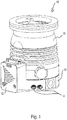
- FIG. 1 A vacuum device 10 designed as a turbomolecular pump is shown with a control unit 12 and two connections 14 for accessory units (not shown).
- Various accessories such as holding elements, fans, flood valves, sealing gas valves, control relays, pressure measuring devices and / or integrated measuring tubes, can each be connected to the connections 14.
- One or, as shown here, two or more connections 14 can be provided.
- the connections 14 are arranged on a lower part 16 of a housing of the vacuum device.
- one or more connections 14 can also be arranged elsewhere, for example on an upper part 18 of the housing and / or on and / or in the control unit 12 or its housing.
- FIG. 2 shown sectional view of the vacuum device 10 of the Fig. 1
- the section plane runs essentially through the lower part 16, the vacuum device 10 being rotated essentially by 180 °, that is to say the vacuum device is viewed from below.
- Electronics 20 is visible, which itself, alternatively or in addition to the control unit 12, can form a control unit for accessory units connected to the connections 14.
- the control unit 12 can comprise, for example, an engine control.
- the electronics 20 can be configured as a control unit for one or more accessory units, for example, in such a way that the accessory unit can also be operated when the control unit 12 is not connected.
- Fig. 3 shows a similar sectional view as Fig. 2 , but here two connections 22 are additionally shown, each of which is connected to a connection 14 of the vacuum device 10. Starting from a respective connection 22, a line 24 runs to a respective accessory unit, which is not shown here.
- the connections 14 are designed as sockets and the connections 22 as plugs.
- the first exemplary connection diagram shown is provided with two accessory units 26 for connection to a vacuum device 10.
- the vacuum device 10 comprises a control unit 12 with two connections 14 for respective connections 22 of the accessory units 26.
- the connections 22 are each connected to the accessory unit 26 via a line 24, however, for example, a configuration of the connector 22 directly on the accessory unit 26 is also conceivable .
- An accessory unit 26 could form a plug-in module.
- a connection 14 can also be connected to the control unit 12 or the vacuum device 10 via a line or otherwise, but be made separately.
- a second connection diagram is in Fig. 5 shown.
- a vacuum device 10 comprises a connection 14 provided on the housing of the vacuum device 10, an accessory unit 26 with a connection 22 being provided for connection to the connection 14 arranged on the vacuum device 10.
- a control unit 12 comprises three connections 14.
- a connection 22 is provided for connection to one of the three connections 14 and connects the control unit 12 to an accessory unit 26 which is attached to and / or in the vacuum device 10.
- This accessory unit 26 can have, for example, a heating element for heating the vacuum device 10 and / or a sensor for detecting a parameter prevailing in or on the vacuum device 10.
- the third connection diagram shown includes a vacuum device 10, a control unit 12 with two connections 14.
- a further connection 14 is provided on a housing part of the vacuum device 10 separately from the control unit 12.
- the connection 14 is connected to the control unit 12 via a line 27.
- the line 27 runs inside and / or in the housing of the vacuum device 10 or the control unit 12.
- the connection 14 can be used, for example, both for a mechanical connection of the accessory unit 26 with the vacuum device 10 and for an electrical and / or information technology connection of the accessory unit 26 be formed on the control unit 12.
- the control unit 12 can generally be designed as a component that is adjacent to the main housing of the vacuum device 10 and / or can also be integrated, that is to say can also be provided elsewhere in the vacuum device 10.
- connection 22 which is connected directly to the control unit 26. No flexible line is therefore provided. However, such an arrangement can alternatively or additionally be provided. Via the connection 22, the accessory unit 26 is connected to the connection 14 of the vacuum device 10 both mechanically and electrically and / or in terms of information technology.
- FIG. 7 A fourth connection diagram is shown, in which a control unit 12 is arranged integrated in a housing of the vacuum device 10.
- the control unit 12 comprises a connection 14.
- the vacuum device 10 comprises a further connection 14, which is connected to the control unit via a line 27.
- Two connection units (not shown) can be connected to the respective connections 14 via connections 22.
- FIG. 8 A vacuum device 10 with a connection 14 is shown.
- an accessory unit 26 can be connected to the connector 14, which has a connector 22 for connecting the accessory unit 26 to the connector 14 of the vacuum device 10.
- the accessory unit 26 also includes a connector 14 for connecting one or more additional accessory units.
- An adapter 28, for example, can be connected to one of the connections 14 via a connection 22 and has a plurality of connections 14 for connecting further accessories.
- connection 14 of a vacuum device not shown here, is shown, which has a supply contact 30 and a communication contact 32.
- An accessory unit 26 also has a supply contact 34 and a communication contact 36 at a connection 22.
- the accessory unit 26 can therefore communicate with a control unit via the communication contacts 36 and 32 of the connections 22 and 14, respectively.
- the communication contacts 36 and 32 can be connected to a UART (Universal Asynchronous Receiver Transmitter; German: universal asynchronous receiver / transmitter), which enables a circuit for realizing serial communication (in other words: communication via a serial interface).
- UART Universal Asynchronous Receiver Transmitter
- German universal asynchronous receiver / transmitter
- FIG. 9 Down in Fig. 9 an accessory unit 26 with only one supply contact 34 is shown.
- This accessory unit 26 can be supplied with electrical energy via the supply contacts 34 and 30.
- This accessory unit 26 illustrates an accessory unit of an older generation than the upper accessory unit 26.
- the vacuum device with the connection 14 can advantageously be designed such that the lower accessory unit 26 even without complete automatic recognition (for example, it is only recognized that an accessory unit 26 is connected, but the type (or type or model) of the accessory unit 26 ) is operable.
- a communication device and / or a communication contact can, for example, also be retrofittable on an accessory unit, for example via a switch connected between the connector 22 of the lower accessory unit 26 and the connector 14 of the vacuum device Detection unit 38.
- the detection unit 38 has a supply contact 30 at the connection 14 for supplying the accessory unit 26. In addition to the supply contact 34, it has a communication contact 36 at the connection 22.
- the detection unit 38 can use this, for example, to output a signal which indicates the type of the connected accessory unit 26.
- the signal or the type can be preprogrammed and / or can be entered, for example.
- Fig. 10 shows a control unit 12 and an accessory unit 26.
- the (control unit side) connection 14 on the control unit 12 can contain a plurality of contacts 40.
- An example is in Fig. 10 the bottom contact with reference number 40.
- the connection 22 on the accessories side can also contain a plurality of contacts 42.
- the number of contacts 40 of the control unit-side connection 14 and the number of contacts 42 of the accessory-side connection 22 can be identical.
- the control unit 12 may be included in or connected to the vacuum device 10 as described above.
- Fig. 11 shows an embodiment of the vacuum device-side connection 14 and the accessory-side connection 22.
- a measuring resistor 48 can be connected to a predetermined communication contact 44 (which can serve, for example, as an Rx line of a serial interface) of the communication contacts 40.
- the measuring resistor 48 can be connected to a further node 50 which, for example, provides a supply voltage.
- the supply voltage can, for example, also be provided to the accessory unit 26 via one of the communication contacts 40.
- the communication contact 44 can also be connected to a microcontroller 56.
- the microcontroller 56 can, for example, provide a UART or be a UART.
- the microcontroller 56 can be set up to either use the predetermined communication contact 44 To provide communication in accordance with the specified communication protocol (for example in accordance with a serial interface), for example for the detection of active accessory units, or the specified communication contact 44 as a measuring line for an analog value, for example a voltage which is, for example, dependent on the measuring resistor 48 and one in one Accessory built-in resistance to be used, for example, in the detection of passive accessories.
- the specified communication contact 44 for example in accordance with a serial interface
- the specified communication contact 44 as a measuring line for an analog value, for example a voltage which is, for example, dependent on the measuring resistor 48 and one in one Accessory built-in resistance to be used, for example, in the detection of passive accessories.
- a identification resistor 52 is connected to a communication contact 46 of the communication contacts 40 at the interface 22 on the accessory side.
- the characteristic resistor 52 can be connected to ground 54.
- the arrangement shown can be determined when connecting the accessory unit 26 with the characteristic resistor 52 to the vacuum device, and a voltage drop across the measuring resistor 48 can be determined, and so can be recognized that an accessory unit 26 is connected to the vacuum device 10.
- the size of the characteristic resistor 52 can be determined by determining the magnitude of the voltage drop, and the accessory unit 26 can thus be recognized (in other words, identified).
- Fig. 12 shows a flow diagram of a method according to the invention.
- the method starts at 1202. Alternatively, the method can also start before step 1226.
- the system switches to digital input and output.
- an attempt is made to identify an active accessory, for example by receiving a response (or waiting for a response) to a message in accordance with the predetermined communication protocol.
- a comparison is made with a list 1208 (or database) of active accessory units, for example it is determined whether an active accessory unit can be identified from the list 1208 of active accessory units with the aid of a received message.
- step 1226 If an active accessory unit was not recognized, the method continues in step 1226. If an active accessory has been detected, the method continues in step 1212. In step 1212, the recognized accessory is entered into a list 1218 (or database) of accessories (connected to the vacuum device). The process then continues with step 1214, in which it is checked whether the recognized accessory unit is still connected. If it is recognized in 1214 that the recognized accessory unit is still connected, the connection to the accessory unit is maintained in 1216 and the check in step 1214 is carried out again after a predetermined timer has expired. In step 1226, a switch is made to analog input. In 1228, an attempt is made to detect a passive accessory, for example, by determining whether an electrical resistor is connected to the control unit connector.
- a comparison is made with a list 1230 (or database) of passive accessory units, for example it is determined whether a passive accessory unit can be identified from the list 1230 of passive accessory units with the aid of a determined resistance.
- 1220 it is determined whether a passive accessory unit has been recognized. If a passive accessory is not recognized, the method continues in step 1204. If a passive accessory has been identified, the identified accessory is registered in the list 1218 of connected accessories in step 1222. In 1224 the expiry of a predetermined timer is monitored. It is then determined in 1228 whether the previously recognized passive accessory unit is still connected.
Landscapes
- Engineering & Computer Science (AREA)
- Mechanical Engineering (AREA)
- General Engineering & Computer Science (AREA)
- Non-Positive Displacement Air Blowers (AREA)
- Compressors, Vaccum Pumps And Other Relevant Systems (AREA)
Priority Applications (2)
| Application Number | Priority Date | Filing Date | Title |
|---|---|---|---|
| EP19201918.0A EP3647600B1 (fr) | 2019-10-08 | 2019-10-08 | Identification d'un périphérique connecté électriquement |
| JP2020159318A JP7005715B2 (ja) | 2019-10-08 | 2020-09-24 | 真空機器及び真空機器を運転する方法 |
Applications Claiming Priority (1)
| Application Number | Priority Date | Filing Date | Title |
|---|---|---|---|
| EP19201918.0A EP3647600B1 (fr) | 2019-10-08 | 2019-10-08 | Identification d'un périphérique connecté électriquement |
Publications (2)
| Publication Number | Publication Date |
|---|---|
| EP3647600A1 true EP3647600A1 (fr) | 2020-05-06 |
| EP3647600B1 EP3647600B1 (fr) | 2022-05-18 |
Family
ID=68242311
Family Applications (1)
| Application Number | Title | Priority Date | Filing Date |
|---|---|---|---|
| EP19201918.0A Active EP3647600B1 (fr) | 2019-10-08 | 2019-10-08 | Identification d'un périphérique connecté électriquement |
Country Status (2)
| Country | Link |
|---|---|
| EP (1) | EP3647600B1 (fr) |
| JP (1) | JP7005715B2 (fr) |
Cited By (1)
| Publication number | Priority date | Publication date | Assignee | Title |
|---|---|---|---|---|
| EP4006350A1 (fr) * | 2021-12-09 | 2022-06-01 | Pfeiffer Vacuum Technology AG | Pompe à vide |
Families Citing this family (2)
| Publication number | Priority date | Publication date | Assignee | Title |
|---|---|---|---|---|
| JP7473498B2 (ja) | 2021-03-31 | 2024-04-23 | 株式会社デンソー | 通信装置、基地局、及び通信方法 |
| EP4071364A1 (fr) * | 2022-06-30 | 2022-10-12 | Pfeiffer Vacuum Technology AG | Appareil sous vide, dispositif d'évaluation, système de communication, ainsi que procédé permettant de faire fonctionner un appareil sous vide et procédé permettant de faire fonctionner un dispositif d'évaluation |
Citations (3)
| Publication number | Priority date | Publication date | Assignee | Title |
|---|---|---|---|---|
| US6606536B1 (en) * | 1999-02-25 | 2003-08-12 | Seiko Instruments Inc. | Magnetic bearing device and magnetic bearing control device |
| EP3096021A1 (fr) * | 2015-05-20 | 2016-11-23 | Pfeiffer Vacuum Gmbh | Télé-diagnostic d'appareils sous vide |
| US20180032350A1 (en) * | 2016-08-01 | 2018-02-01 | Samsung Electronics Co., Ltd. | Method for recognizing external device and electronic device supporting the same |
Family Cites Families (2)
| Publication number | Priority date | Publication date | Assignee | Title |
|---|---|---|---|---|
| US6272400B1 (en) | 1998-07-13 | 2001-08-07 | Helix Technology Corporation | Vacuum network controller |
| DE102014116555A1 (de) * | 2014-11-12 | 2016-05-12 | Pfeiffer Vacuum Gmbh | Vakuumgerät |
-
2019
- 2019-10-08 EP EP19201918.0A patent/EP3647600B1/fr active Active
-
2020
- 2020-09-24 JP JP2020159318A patent/JP7005715B2/ja active Active
Patent Citations (3)
| Publication number | Priority date | Publication date | Assignee | Title |
|---|---|---|---|---|
| US6606536B1 (en) * | 1999-02-25 | 2003-08-12 | Seiko Instruments Inc. | Magnetic bearing device and magnetic bearing control device |
| EP3096021A1 (fr) * | 2015-05-20 | 2016-11-23 | Pfeiffer Vacuum Gmbh | Télé-diagnostic d'appareils sous vide |
| US20180032350A1 (en) * | 2016-08-01 | 2018-02-01 | Samsung Electronics Co., Ltd. | Method for recognizing external device and electronic device supporting the same |
Cited By (1)
| Publication number | Priority date | Publication date | Assignee | Title |
|---|---|---|---|---|
| EP4006350A1 (fr) * | 2021-12-09 | 2022-06-01 | Pfeiffer Vacuum Technology AG | Pompe à vide |
Also Published As
| Publication number | Publication date |
|---|---|
| EP3647600B1 (fr) | 2022-05-18 |
| JP2021060034A (ja) | 2021-04-15 |
| JP7005715B2 (ja) | 2022-01-24 |
Similar Documents
| Publication | Publication Date | Title |
|---|---|---|
| EP3647600B1 (fr) | Identification d'un périphérique connecté électriquement | |
| DE102006030706B4 (de) | System und Verfahren zur Steuerung von busvernetzten Geräten über einen offenen Feldbus | |
| EP1455278B1 (fr) | Méthode pour l'identification d'un dispositif électronique | |
| EP3497524B1 (fr) | Sous-programme d'initialisation automatique dans un systeme d'automatisation | |
| DE3236812A1 (de) | Fernwirksystem | |
| EP2529460B1 (fr) | Module d'alimentation électrique | |
| DE102009038760B3 (de) | Verfahren zur Datenkommunikation zwischen einem Automatisierungsgerät und einem Datenverarbeitungsgerät sowie Schnittstellentreiberprogramm und Schnittstellenumsetzer hierzu | |
| DE102012105483A1 (de) | Verfahren zum Übertragen von Informationen von einem Energiespeichermodul und Energiespeichermodul | |
| EP2605230A2 (fr) | Outil diagnostique pour la connexion sur une douille de diagnostic d'un véhicule automobile | |
| DE102012223530B4 (de) | Dynamische Leitungsterminierung von Kommunikationsbussen in Überwachungsschaltungen für Batteriemodule sowie ein Verfahren zur Durchführung der Leitungsterminierung bei der Initialisierung des Überwachungssystems | |
| EP1649331A1 (fr) | Systeme et procede pour identifier des composants d'automatisation | |
| DE102019127195A1 (de) | Modulares Interfacesystem zum Anschließen einer Steuerungseinrichtung und von Feldgeräte | |
| EP2327135B1 (fr) | Module fonctionnel et module de couplage d'une commande d'appareil de commutation, et système de commande d'appareil de commutation | |
| DE102007043769A1 (de) | Gerät, Verfahren zur Adressierung, Umrichter und Verfahren zur sicheren Datenübertragung | |
| EP3617520B1 (fr) | Appareil sous vide, unité accessoire et système | |
| DE212012000249U1 (de) | Vorrichtung zum eigensicheren Versorgen, Ansteuern und/oder Auswerten von Feldgeräten im explosionsgeschützten Bereich | |
| EP2778811A1 (fr) | Dispositif pour un système d'interface AS | |
| DE102014224642B3 (de) | Feldbuskommunikationsmodul | |
| EP3709108B1 (fr) | Configuration d'une entrée bipolaire | |
| EP2196670B1 (fr) | Appareil pouvant être connecté avec un composant sous vide | |
| BE1026569B1 (de) | Steuer- und Datenübertragungsanlage zur Unterstützung verschiedener Kommunikationsprotokolle und ein Adaptermodul | |
| DE102010038459A1 (de) | Sicherheitssystem | |
| EP1457399B1 (fr) | Procédé d'initialisation pour un bus de données | |
| DE112020001869T5 (de) | Intermittierende aktoren, bestromt durch eine twisted-wire-verbindung | |
| EP3948448A1 (fr) | Procédé de modification d'un logiciel de commande d'un système d'automatisation |
Legal Events
| Date | Code | Title | Description |
|---|---|---|---|
| PUAI | Public reference made under article 153(3) epc to a published international application that has entered the european phase |
Free format text: ORIGINAL CODE: 0009012 |
|
| STAA | Information on the status of an ep patent application or granted ep patent |
Free format text: STATUS: THE APPLICATION HAS BEEN PUBLISHED |
|
| AK | Designated contracting states |
Kind code of ref document: A1 Designated state(s): AL AT BE BG CH CY CZ DE DK EE ES FI FR GB GR HR HU IE IS IT LI LT LU LV MC MK MT NL NO PL PT RO RS SE SI SK SM TR |
|
| AX | Request for extension of the european patent |
Extension state: BA ME |
|
| STAA | Information on the status of an ep patent application or granted ep patent |
Free format text: STATUS: REQUEST FOR EXAMINATION WAS MADE |
|
| 17P | Request for examination filed |
Effective date: 20201106 |
|
| RBV | Designated contracting states (corrected) |
Designated state(s): AL AT BE BG CH CY CZ DE DK EE ES FI FR GB GR HR HU IE IS IT LI LT LU LV MC MK MT NL NO PL PT RO RS SE SI SK SM TR |
|
| GRAP | Despatch of communication of intention to grant a patent |
Free format text: ORIGINAL CODE: EPIDOSNIGR1 |
|
| STAA | Information on the status of an ep patent application or granted ep patent |
Free format text: STATUS: GRANT OF PATENT IS INTENDED |
|
| INTG | Intention to grant announced |
Effective date: 20220207 |
|
| GRAS | Grant fee paid |
Free format text: ORIGINAL CODE: EPIDOSNIGR3 |
|
| GRAA | (expected) grant |
Free format text: ORIGINAL CODE: 0009210 |
|
| STAA | Information on the status of an ep patent application or granted ep patent |
Free format text: STATUS: THE PATENT HAS BEEN GRANTED |
|
| AK | Designated contracting states |
Kind code of ref document: B1 Designated state(s): AL AT BE BG CH CY CZ DE DK EE ES FI FR GB GR HR HU IE IS IT LI LT LU LV MC MK MT NL NO PL PT RO RS SE SI SK SM TR |
|
| REG | Reference to a national code |
Ref country code: GB Ref legal event code: FG4D Free format text: NOT ENGLISH |
|
| REG | Reference to a national code |
Ref country code: CH Ref legal event code: EP |
|
| REG | Reference to a national code |
Ref country code: IE Ref legal event code: FG4D Free format text: LANGUAGE OF EP DOCUMENT: GERMAN |
|
| REG | Reference to a national code |
Ref country code: DE Ref legal event code: R096 Ref document number: 502019004404 Country of ref document: DE |
|
| REG | Reference to a national code |
Ref country code: AT Ref legal event code: REF Ref document number: 1493290 Country of ref document: AT Kind code of ref document: T Effective date: 20220615 |
|
| REG | Reference to a national code |
Ref country code: LT Ref legal event code: MG9D |
|
| REG | Reference to a national code |
Ref country code: NL Ref legal event code: MP Effective date: 20220518 |
|
| PG25 | Lapsed in a contracting state [announced via postgrant information from national office to epo] |
Ref country code: SE Free format text: LAPSE BECAUSE OF FAILURE TO SUBMIT A TRANSLATION OF THE DESCRIPTION OR TO PAY THE FEE WITHIN THE PRESCRIBED TIME-LIMIT Effective date: 20220518 Ref country code: PT Free format text: LAPSE BECAUSE OF FAILURE TO SUBMIT A TRANSLATION OF THE DESCRIPTION OR TO PAY THE FEE WITHIN THE PRESCRIBED TIME-LIMIT Effective date: 20220919 Ref country code: NO Free format text: LAPSE BECAUSE OF FAILURE TO SUBMIT A TRANSLATION OF THE DESCRIPTION OR TO PAY THE FEE WITHIN THE PRESCRIBED TIME-LIMIT Effective date: 20220818 Ref country code: NL Free format text: LAPSE BECAUSE OF FAILURE TO SUBMIT A TRANSLATION OF THE DESCRIPTION OR TO PAY THE FEE WITHIN THE PRESCRIBED TIME-LIMIT Effective date: 20220518 Ref country code: LT Free format text: LAPSE BECAUSE OF FAILURE TO SUBMIT A TRANSLATION OF THE DESCRIPTION OR TO PAY THE FEE WITHIN THE PRESCRIBED TIME-LIMIT Effective date: 20220518 Ref country code: HR Free format text: LAPSE BECAUSE OF FAILURE TO SUBMIT A TRANSLATION OF THE DESCRIPTION OR TO PAY THE FEE WITHIN THE PRESCRIBED TIME-LIMIT Effective date: 20220518 Ref country code: GR Free format text: LAPSE BECAUSE OF FAILURE TO SUBMIT A TRANSLATION OF THE DESCRIPTION OR TO PAY THE FEE WITHIN THE PRESCRIBED TIME-LIMIT Effective date: 20220819 Ref country code: FI Free format text: LAPSE BECAUSE OF FAILURE TO SUBMIT A TRANSLATION OF THE DESCRIPTION OR TO PAY THE FEE WITHIN THE PRESCRIBED TIME-LIMIT Effective date: 20220518 Ref country code: ES Free format text: LAPSE BECAUSE OF FAILURE TO SUBMIT A TRANSLATION OF THE DESCRIPTION OR TO PAY THE FEE WITHIN THE PRESCRIBED TIME-LIMIT Effective date: 20220518 Ref country code: BG Free format text: LAPSE BECAUSE OF FAILURE TO SUBMIT A TRANSLATION OF THE DESCRIPTION OR TO PAY THE FEE WITHIN THE PRESCRIBED TIME-LIMIT Effective date: 20220818 |
|
| PG25 | Lapsed in a contracting state [announced via postgrant information from national office to epo] |
Ref country code: RS Free format text: LAPSE BECAUSE OF FAILURE TO SUBMIT A TRANSLATION OF THE DESCRIPTION OR TO PAY THE FEE WITHIN THE PRESCRIBED TIME-LIMIT Effective date: 20220518 Ref country code: PL Free format text: LAPSE BECAUSE OF FAILURE TO SUBMIT A TRANSLATION OF THE DESCRIPTION OR TO PAY THE FEE WITHIN THE PRESCRIBED TIME-LIMIT Effective date: 20220518 Ref country code: LV Free format text: LAPSE BECAUSE OF FAILURE TO SUBMIT A TRANSLATION OF THE DESCRIPTION OR TO PAY THE FEE WITHIN THE PRESCRIBED TIME-LIMIT Effective date: 20220518 Ref country code: IS Free format text: LAPSE BECAUSE OF FAILURE TO SUBMIT A TRANSLATION OF THE DESCRIPTION OR TO PAY THE FEE WITHIN THE PRESCRIBED TIME-LIMIT Effective date: 20220918 |
|
| PG25 | Lapsed in a contracting state [announced via postgrant information from national office to epo] |
Ref country code: SM Free format text: LAPSE BECAUSE OF FAILURE TO SUBMIT A TRANSLATION OF THE DESCRIPTION OR TO PAY THE FEE WITHIN THE PRESCRIBED TIME-LIMIT Effective date: 20220518 Ref country code: SK Free format text: LAPSE BECAUSE OF FAILURE TO SUBMIT A TRANSLATION OF THE DESCRIPTION OR TO PAY THE FEE WITHIN THE PRESCRIBED TIME-LIMIT Effective date: 20220518 Ref country code: RO Free format text: LAPSE BECAUSE OF FAILURE TO SUBMIT A TRANSLATION OF THE DESCRIPTION OR TO PAY THE FEE WITHIN THE PRESCRIBED TIME-LIMIT Effective date: 20220518 Ref country code: EE Free format text: LAPSE BECAUSE OF FAILURE TO SUBMIT A TRANSLATION OF THE DESCRIPTION OR TO PAY THE FEE WITHIN THE PRESCRIBED TIME-LIMIT Effective date: 20220518 Ref country code: DK Free format text: LAPSE BECAUSE OF FAILURE TO SUBMIT A TRANSLATION OF THE DESCRIPTION OR TO PAY THE FEE WITHIN THE PRESCRIBED TIME-LIMIT Effective date: 20220518 |
|
| REG | Reference to a national code |
Ref country code: DE Ref legal event code: R097 Ref document number: 502019004404 Country of ref document: DE |
|
| PLBE | No opposition filed within time limit |
Free format text: ORIGINAL CODE: 0009261 |
|
| STAA | Information on the status of an ep patent application or granted ep patent |
Free format text: STATUS: NO OPPOSITION FILED WITHIN TIME LIMIT |
|
| PG25 | Lapsed in a contracting state [announced via postgrant information from national office to epo] |
Ref country code: AL Free format text: LAPSE BECAUSE OF FAILURE TO SUBMIT A TRANSLATION OF THE DESCRIPTION OR TO PAY THE FEE WITHIN THE PRESCRIBED TIME-LIMIT Effective date: 20220518 |
|
| 26N | No opposition filed |
Effective date: 20230221 |
|
| PG25 | Lapsed in a contracting state [announced via postgrant information from national office to epo] |
Ref country code: SI Free format text: LAPSE BECAUSE OF FAILURE TO SUBMIT A TRANSLATION OF THE DESCRIPTION OR TO PAY THE FEE WITHIN THE PRESCRIBED TIME-LIMIT Effective date: 20220518 Ref country code: MC Free format text: LAPSE BECAUSE OF FAILURE TO SUBMIT A TRANSLATION OF THE DESCRIPTION OR TO PAY THE FEE WITHIN THE PRESCRIBED TIME-LIMIT Effective date: 20220518 |
|
| REG | Reference to a national code |
Ref country code: CH Ref legal event code: PL |
|
| REG | Reference to a national code |
Ref country code: BE Ref legal event code: MM Effective date: 20221031 |
|
| PG25 | Lapsed in a contracting state [announced via postgrant information from national office to epo] |
Ref country code: LU Free format text: LAPSE BECAUSE OF NON-PAYMENT OF DUE FEES Effective date: 20221008 |
|
| PG25 | Lapsed in a contracting state [announced via postgrant information from national office to epo] |
Ref country code: LI Free format text: LAPSE BECAUSE OF NON-PAYMENT OF DUE FEES Effective date: 20221031 Ref country code: FR Free format text: LAPSE BECAUSE OF NON-PAYMENT OF DUE FEES Effective date: 20221031 Ref country code: CH Free format text: LAPSE BECAUSE OF NON-PAYMENT OF DUE FEES Effective date: 20221031 |
|
| PG25 | Lapsed in a contracting state [announced via postgrant information from national office to epo] |
Ref country code: BE Free format text: LAPSE BECAUSE OF NON-PAYMENT OF DUE FEES Effective date: 20221031 |
|
| PG25 | Lapsed in a contracting state [announced via postgrant information from national office to epo] |
Ref country code: IE Free format text: LAPSE BECAUSE OF NON-PAYMENT OF DUE FEES Effective date: 20221008 |
|
| PGFP | Annual fee paid to national office [announced via postgrant information from national office to epo] |
Ref country code: GB Payment date: 20231020 Year of fee payment: 5 |
|
| PGFP | Annual fee paid to national office [announced via postgrant information from national office to epo] |
Ref country code: IT Payment date: 20231026 Year of fee payment: 5 Ref country code: CZ Payment date: 20231004 Year of fee payment: 5 |
|
| PG25 | Lapsed in a contracting state [announced via postgrant information from national office to epo] |
Ref country code: HU Free format text: LAPSE BECAUSE OF FAILURE TO SUBMIT A TRANSLATION OF THE DESCRIPTION OR TO PAY THE FEE WITHIN THE PRESCRIBED TIME-LIMIT; INVALID AB INITIO Effective date: 20191008 |
|
| PG25 | Lapsed in a contracting state [announced via postgrant information from national office to epo] |
Ref country code: CY Free format text: LAPSE BECAUSE OF FAILURE TO SUBMIT A TRANSLATION OF THE DESCRIPTION OR TO PAY THE FEE WITHIN THE PRESCRIBED TIME-LIMIT Effective date: 20220511 |
|
| PGFP | Annual fee paid to national office [announced via postgrant information from national office to epo] |
Ref country code: DE Payment date: 20231227 Year of fee payment: 5 |
|
| PG25 | Lapsed in a contracting state [announced via postgrant information from national office to epo] |
Ref country code: MK Free format text: LAPSE BECAUSE OF FAILURE TO SUBMIT A TRANSLATION OF THE DESCRIPTION OR TO PAY THE FEE WITHIN THE PRESCRIBED TIME-LIMIT Effective date: 20220511 |
|
| PG25 | Lapsed in a contracting state [announced via postgrant information from national office to epo] |
Ref country code: TR Free format text: LAPSE BECAUSE OF FAILURE TO SUBMIT A TRANSLATION OF THE DESCRIPTION OR TO PAY THE FEE WITHIN THE PRESCRIBED TIME-LIMIT Effective date: 20220511 |