EP3647555A1 - Internal combustion engine and vehicle - Google Patents
Internal combustion engine and vehicle Download PDFInfo
- Publication number
- EP3647555A1 EP3647555A1 EP18824775.3A EP18824775A EP3647555A1 EP 3647555 A1 EP3647555 A1 EP 3647555A1 EP 18824775 A EP18824775 A EP 18824775A EP 3647555 A1 EP3647555 A1 EP 3647555A1
- Authority
- EP
- European Patent Office
- Prior art keywords
- hole
- support member
- internal combustion
- combustion engine
- arm
- Prior art date
- Legal status (The legal status is an assumption and is not a legal conclusion. Google has not performed a legal analysis and makes no representation as to the accuracy of the status listed.)
- Granted
Links
Images




Classifications
-
- F—MECHANICAL ENGINEERING; LIGHTING; HEATING; WEAPONS; BLASTING
- F01—MACHINES OR ENGINES IN GENERAL; ENGINE PLANTS IN GENERAL; STEAM ENGINES
- F01L—CYCLICALLY OPERATING VALVES FOR MACHINES OR ENGINES
- F01L1/00—Valve-gear or valve arrangements, e.g. lift-valve gear
- F01L1/12—Transmitting gear between valve drive and valve
- F01L1/18—Rocking arms or levers
- F01L1/185—Overhead end-pivot rocking arms
-
- F—MECHANICAL ENGINEERING; LIGHTING; HEATING; WEAPONS; BLASTING
- F01—MACHINES OR ENGINES IN GENERAL; ENGINE PLANTS IN GENERAL; STEAM ENGINES
- F01L—CYCLICALLY OPERATING VALVES FOR MACHINES OR ENGINES
- F01L1/00—Valve-gear or valve arrangements, e.g. lift-valve gear
- F01L1/20—Adjusting or compensating clearance
-
- F—MECHANICAL ENGINEERING; LIGHTING; HEATING; WEAPONS; BLASTING
- F01—MACHINES OR ENGINES IN GENERAL; ENGINE PLANTS IN GENERAL; STEAM ENGINES
- F01L—CYCLICALLY OPERATING VALVES FOR MACHINES OR ENGINES
- F01L1/00—Valve-gear or valve arrangements, e.g. lift-valve gear
- F01L1/46—Component parts, details, or accessories, not provided for in preceding subgroups
-
- F—MECHANICAL ENGINEERING; LIGHTING; HEATING; WEAPONS; BLASTING
- F01—MACHINES OR ENGINES IN GENERAL; ENGINE PLANTS IN GENERAL; STEAM ENGINES
- F01L—CYCLICALLY OPERATING VALVES FOR MACHINES OR ENGINES
- F01L13/00—Modifications of valve-gear to facilitate reversing, braking, starting, changing compression ratio, or other specific operations
-
- F—MECHANICAL ENGINEERING; LIGHTING; HEATING; WEAPONS; BLASTING
- F01—MACHINES OR ENGINES IN GENERAL; ENGINE PLANTS IN GENERAL; STEAM ENGINES
- F01L—CYCLICALLY OPERATING VALVES FOR MACHINES OR ENGINES
- F01L1/00—Valve-gear or valve arrangements, e.g. lift-valve gear
- F01L1/12—Transmitting gear between valve drive and valve
- F01L1/18—Rocking arms or levers
- F01L2001/186—Split rocking arms, e.g. rocker arms having two articulated parts and means for varying the relative position of these parts or for selectively connecting the parts to move in unison
-
- F—MECHANICAL ENGINEERING; LIGHTING; HEATING; WEAPONS; BLASTING
- F01—MACHINES OR ENGINES IN GENERAL; ENGINE PLANTS IN GENERAL; STEAM ENGINES
- F01L—CYCLICALLY OPERATING VALVES FOR MACHINES OR ENGINES
- F01L1/00—Valve-gear or valve arrangements, e.g. lift-valve gear
- F01L1/12—Transmitting gear between valve drive and valve
- F01L1/18—Rocking arms or levers
- F01L2001/187—Clips, e.g. for retaining rocker arm on pivot
Definitions
- the present invention relates to an internal combustion engine and a vehicle.
- Patent Document No. 1 discloses a valve mechanism that includes a lash adjuster as the support member.
- Patent Document No. 1 Japanese Laid-Open Patent Publication No. 2009-185753
- the rocker arm is held down by the cam. Therefore, the support member is held down by the cam with the rocker arm therebetween.
- the support member is only inserted into the hole of the cylinder head and is not particularly secured to the cylinder head. While the internal combustion engine is running, a load in the axial direction of the support member is repeatedly generated on the support member. Therefore, the support member may possibly rise from the hole, leading to problems such as fretting wear.
- the support member is secured to the cylinder head using screws in order to prevent the rise, it will detract from the ease of installment of the support member.
- the present invention has been made in view of the above, and an object thereof is to provide an internal combustion engine that allows a support member to be installed easily while preventing fretting wear, or the like, due to rising of the support member, and a vehicle having the same.
- An internal combustion engine includes: a cylinder member formed with a hole; a port formed in the cylinder member; a valve installed in the cylinder member that opens/closes the port; a cam shaft rotatably supported on the cylinder member; a cam provided on the cam shaft; a columnar support member at least a portion of which is inserted into the hole of the cylinder member; a rocker arm that includes a supported portion pivotally supported on the support member, a pressed portion pressed by the cam, and an abutting portion to abut on the valve; and a securing member that secures the support member inside the hole.
- the securing member includes a first contact portion to be in contact with the support member, a second contact portion to be in contact with the cylinder member, and an elastic portion interposed between the first contact portion and the second contact portion.
- the securing member is a plunger mechanism that includes a spring arranged inside the support member, and a presser at least a portion of which is arranged outside the support member and that is connected to the spring.
- the securing member can be configured to be simple and compact.
- the spring constant, etc., of the spring By appropriately setting the spring constant, etc., of the spring, the ease of operation of inserting the support member into the hole and the prevention of rising of the support member can be realized in a well-balanced manner.
- the securing member is a snap ring that is fitted to the support member.
- the securing member can be configured to be simple and compact.
- the securing member is a ring-shaped coil spring that is wound around the support member.
- the securing member can be configured to be simple and compact.
- a groove that engages with the securing member is formed on an inner surface of the hole of the cylinder member.
- the securing member engages with the groove, thus securing the support member inside the hole.
- the support member is even less likely to rise. Therefore, the ease of installment of the support member and the prevention of fretting wear, or the like, due to rising of the support member can be both realized at a high level.
- the groove in a cross-section that passes through a part of the groove and that includes a center line of the hole, has a sloped surface that is inclined relative to the center line of the hole so as to come closer to the center line of the hole while extending toward the rocker arm along a direction of the center line of the hole.
- the support member is even less likely to rise. Therefore, it is possible to even better prevent fretting wear, or the like, due to rising of the support member.
- the groove is a cone-shaped or circular columnar-shaped groove having an axis that is inclined relative to the center line of the hole.
- the groove can be machined by inserting a tool such as a drill or an endmill into the hole of the cylinder member from outside in a direction that is slanted relative to the center line of the hole. Therefore, the groove can be formed in a simple and inexpensive manner.
- the hole and the support member are each formed in a circular columnar shape.
- the groove is a circumferential groove formed on an inner circumferential surface of the hole.
- the groove is formed only at one point in the circumferential direction of the hole, if the position at which the groove is machined is shifted in the circumferential direction, the position at which the support member is attached in the circumferential direction may possibly be shifted.
- the groove since the groove is formed in a circumferential pattern, the position at which the support member is attached in the circumferential direction is prevented from being shifted. Therefore, even if the machining precision of the groove is relatively low, it is possible to properly machine the groove.
- the groove can be formed in a simple and inexpensive manner.
- the securing member is a plunger mechanism that includes a spring arranged inside the cylinder member, and a presser at least a portion of which is arranged inside the hole of the cylinder member and that is connected to the spring.
- the securing member is a snap ring that is fitted to an inner surface of the hole of the cylinder member.
- the securing member can be configured to be simple and compact.
- the securing member is a ring-shaped coil spring that is fitted to an inner surface of the hole of the cylinder member.
- the securing member can be configured to be simple and compact.
- the securing member is a leaf spring that is secured to an edge of the hole of the cylinder member.
- the securing member can be configured to be simple.
- the rocker arm includes a first arm that includes the supported portion and the abutting portion, and a second arm that includes the pressed portion and is pivotally supported on the first arm.
- the internal combustion engine includes a connecting mechanism that removably connects the first arm and the second arm.
- the support member is configured to be unable to expand/contract in an axial direction of the support member.
- the rocker arm includes the second arm that is pivotally supported on the first arm
- the support member is a member that can contract/expand in the axial direction, such as a lash adjuster
- the relative position between the first arm and the second arm may possibly be shifted following the expansion/contraction of the support member when the connection between the first arm and the second arm is disconnected.
- the second arm may be shifted from the intended position relative to the first arm, and the connecting mechanism may fail to properly connect the first arm and the second arm.
- the support member is unable to expand/contract in the axial direction, it is possible to prevent the lowering of the connection function.
- a vehicle according to the present invention includes the internal combustion engine described above.
- an internal combustion engine that allows easy installment of a support member that supports a rocker arm while preventing fretting wear, or the like, due to rising of the support member, and a vehicle having the same.
- An internal combustion engine according to the present embodiment is installed in a vehicle and used as the drive source of the vehicle.
- a vehicle which may be a straddled vehicle such as a motorcycle, an auto tricycle or an ATV (All Terrain Vehicle) or may be an automobile.
- an internal combustion engine 10 may be arranged in the engine room of an automobile 5 as shown in FIG. 1 .
- the internal combustion engine 10 is a multi-cylinder engine having a plurality of cylinders.
- the internal combustion engine 10 is a 4-stroke engine that goes through the intake stroke, the compression stroke, the combustion stroke and the exhaust stroke.
- FIG. 2 is a partial cross-sectional view of the internal combustion engine 10.
- the internal combustion engine 10 includes a crankcase (not shown), a cylinder body 7 connected to the crankcase, and a cylinder head 12 connected to the cylinder body 7.
- a crankshaft (not shown) is arranged inside the crankcase.
- a plurality of cylinders 6 are provided inside the cylinder body 7.
- a piston 8 is arranged inside each cylinder 6. The piston 8 and the crankshaft are connected by a connecting rod (not shown).
- An intake cam shaft 23 and an exhaust cam shaft 21 are rotatably supported on the cylinder head 12.
- Intake cams 23A are provided on the intake cam shaft 23, and exhaust cams 21A are provided on the exhaust cam shaft 21.
- Intake ports 16 and exhaust ports 14 are formed in the cylinder head 12.
- An intake opening 18 is formed at one end of the intake port 16.
- An exhaust opening 17 is formed on one end of the exhaust port 14.
- the intake port 16 communicates with a combustion chamber 15 through the intake opening 18.
- the exhaust port 14 communicates with the combustion chamber 15 through the exhaust opening 17.
- the intake port 16 serves to guide the mixed gas of the air and the fuel into the combustion chamber 15.
- the exhaust port 14 serves to guide the exhaust gas discharged from the combustion chamber 15 to the outside.
- Intake valves 22 and exhaust valves 20 are installed in the cylinder head 12.
- the intake valve 22 opens/closes the intake opening 18 of the intake port 16.
- the exhaust valve 20 opens/closes the exhaust opening 17 of the exhaust port 14.
- the intake valve 22 and the exhaust valve 20 are so-called poppet valves.
- the intake valve 22 has a shaft portion 22a and an umbrella portion 22b
- the exhaust valve 20 has a shaft portion 20a and an umbrella portion 20b.
- the configuration of the intake valve 22 and the configuration of the exhaust valve 20 are similar to each other, and the configuration of the intake valve 22 will be described below while omitting the description of the configuration of the exhaust valve 20.
- the shaft portion 22a of the intake valve 22 is slidably supported on the cylinder head 12 with a cylinder-shaped sleeve 24 therebetween.
- a valve stem seal 25 is attached to one end of the sleeve 24 and the shaft portion 22a of the intake valve 22.
- the shaft portion 22a of the intake valve 22 extends through the sleeve 24 and the valve stem seal 25.
- a tappet 26 is fitted to the tip of the shaft portion 22a.
- a cotter 28 is attached to the shaft portion 22a of the intake valve 22.
- the cotter 28 is fitted to a valve spring retainer 30.
- the valve spring retainer 30 is secured to the intake valve 22 with the cotter 28 therebetween.
- the valve spring retainer 30 can move, together with the intake valve 22 , in an axial direction of the intake valve 22.
- the intake valve 22 extends through the valve spring retainer 30.
- the internal combustion engine 10 includes a valve spring 32 that provides the intake valve 22 with a force in the direction of closing the intake opening 18 (the upward direction in FIG. 3 ).
- the valve spring 32 is a compression coil spring, and includes a first spring end portion 32a supported on the valve spring retainer 30 and a second spring end portion 32b supported on the cylinder head 12.
- the internal combustion engine 10 includes a rocker arm 40 that receives a force from the intake cam 23A to open/close the intake valve 22.
- the rocker arm 40 is pivotally supported on the cylinder head 12 with a support member 35 therebetween.
- FIG. 4 is a side view of the rocker arm 40 and the support member 35
- FIG. 5 is a plan view of the rocker arm 40 and the support member 35.
- the rocker arm 40 includes a first arm 41 and a second arm 42 including a roller 43.
- FIG. 6 is an exploded perspective view of the first arm 41 and the second arm 42.
- the first arm 41 includes a plate 41A , a plate 41B , an abutting plate 41C and a connecting plate 41D.
- the plate 41A and the plate 41B are arranged parallel to each other.
- the abutting plate 41C and the connecting plate 41D cross the plate 41A and the plate 41B.
- the abutting plate 41C and the connecting plate 41D connect together the plate 41A and the plate 41B.
- the plate 41A is formed with a hole 46A and a hole 48.
- the plate 41B is formed with a hole 46B (see FIG. 7 ) and the hole 48.
- the holes 46A , 46B and 48 extend in the direction parallel to the axial line direction of the intake cam shaft 23 (see FIG. 3 ).
- FIG. 7 is a cross-sectional view taken along line VII-VII of FIG. 4 .
- a cylinder-shaped boss portion 49A is provided around the hole 46A of the plate 41A.
- a connecting pin 60A is slidably inserted inside the hole 46A.
- a bottomed cylinder-shaped cover portion 49B is provided around the hole 46B of the plate 41B.
- the cover portion 49B is provided with a hole 47 having a smaller diameter than the hole 46B , but the hole 47 may be omitted.
- a connecting pin 60B is slidably inserted inside the hole 46B .
- a spring 64 is arranged inside the hole 46B. The spring 64 is present between the cover portion 49B and the connecting pin 60B , and urges the connecting pin 60B toward the plate 41A.
- the second arm 42 is arranged on the inner side of the first arm 41. That is, the second arm 42 is arranged between the plate 41A and the plate 41B.
- the second arm 42 includes a plate 42A , a plate 42B , an abutting plate 42C and a connecting plate 42D.
- the plate 42A and the plate 42B are arranged parallel to each other.
- the abutting plate 42C and the connecting plate 42D cross the plate 42A and the plate 42B.
- the abutting plate 42C and the connecting plate 42D connect together the plate 42A and the plate 42B.
- the plate 42A and the plate 42B are formed with a hole 50 and a hole 52 , respectively.
- the cylinder-shaped roller 43 is rotatably supported on the hole 50 of the plate 42A and the hole 50 of the plate 42B.
- a cylinder-shaped collar 54 is inserted through the holes 50 of the plate 42A and the plate 42B.
- the roller 43 is rotatably supported on the collar 54.
- a connecting pin 62 is slidably inserted inside the collar 54. Since the collar 54 is arranged inside the holes 50 , the connecting pin 62 is slidably inserted inside the holes 50. Note that the collar 54 is not always necessary.
- the connecting pin 62 may rotatably support the roller 43.
- An outer diameter of the connecting pin 60B is less than or equal to an inner diameter of the collar 54.
- the connecting pin 60B is formed so that it can be inserted inside the collar 54.
- An outer diameter of the connecting pin 62 is less than or equal to an inner diameter of the hole 46A.
- the connecting pin 62 is formed so that it can be inserted inside the hole 46A.
- the inner diameter of the collar 54 and the inner diameter of the hole 46A are equal to each other.
- the outer diameter of the connecting pin 60B , the outer diameter of the connecting pin 62 and an outer diameter of the connecting pin 60A are equal to each other.
- the support member 35 , the first arm 41 and the second arm 42 are connected together by a support pin 56.
- the support pin 56 is inserted through the hole 48 of the plate 41A and the hole 48 of the plate 41B of the first arm 41 , and the hole 52 of the plate 42A and the hole 52 of the plate 42B of the second arm 42.
- the first arm 41 and the second arm 42 are pivotally supported on the support member 35 by the support pin 56.
- the second arm 42 is pivotally supported on the first arm 41 by the support pin 56.
- connection switch pin 66 is arranged on the side of the rocker arm 40.
- the connection switch pin 66 is configured to be movable in the direction toward the connecting pin 60A and in the direction away from the connecting pin 60A.
- the connecting pin 60B is located inside the hole 46B and inside the hole 50 (specifically, inside the collar 54 ), and the connecting pin 62 is located inside the hole 50 (specifically, inside the collar 54 ) and inside the hole 46A.
- This state will hereinafter be referred to as the connected state.
- the first arm 41 and the second arm 42 are connected together by the connecting pin 60B and the connecting pin 62.
- the first arm 41 and the second arm 42 are, as a single unit, pivotable about the axis of the support pin 9.
- connection switch pin 66 moves toward the connecting pin 60A , the connecting pins 60A , 62 and 60B are pushed by the connection switch pin 66 and slide rightward in FIG. 7 .
- the connecting pin 60B is located inside the hole 46B and not located inside the hole 50
- the connecting pin 62 is located inside the hole 50 and not located inside the hole 46A.
- This state will hereinafter be referred to as the non-connected state.
- the connecting pin 62 is slidable relative to the connecting pin 60A and the connecting pin 60B.
- the second arm 42 is pivotable about the axis of the support pin 56 relative to the first arm 41. Therefore, the second arm 42 pivots about the axis of the support pin 56 while the first arm 41 does not pivot.
- the portion of the first arm 41 that is supported by the support pin 56 forms a supported portion 41S that is pivotally supported on the cylinder head 12.
- the abutting plate 41C forms an "abutting portion” that is to abut on the intake valve 22 with the tappet 26 therebetween.
- the roller 43 forms a "pressed portion” that is in contact with the intake cam 23A and is pressed by the intake cam 23A.
- the support member 35 that pivotally supports the rocker arm 40 is inserted into a hole 37 formed in the cylinder head 12.
- the cylinder head 12 corresponds to the "cylinder member”.
- a cam carrier (not shown) may be attached to the cylinder head 12 , and the hole 37 , through which the support member 35 is inserted, may be formed in the cam carrier.
- the cylinder head 12 and the cam carrier, combined together correspond to the "cylinder member”.
- another member may be attached to the cylinder head 12 , and the hole 37 may be formed in that member.
- the cylinder head 12 and the other member, combined together correspond to the "cylinder member".
- the support member 35 is formed in a circular columnar shape. Note however that the support member 35 is not limited to a circular columnar shape, but may be a polygonal columnar shape, for example, or any other columnar shape.
- the hole 37 preferably has a cross-sectional shape that corresponds to the cross-sectional shape of the support member 35.
- FIG. 12A is a side view of the support member 35.
- FIG. 12B is a cross-sectional view taken along line XIIb-XIIb of FIG. 12A .
- the support member 35 includes a shaft portion 35A at least a portion of which is inserted into the hole 37 , and a ring portion 35B formed with a hole 35C through which the support pin 56 (see FIG. 3 ) is inserted.
- a ball plunger 39 is provided inside the shaft portion 35A as a securing member that secures the support member 35 in the hole 37.
- the shaft portion 35A of the support member 35 is formed with a hole 35D extending in the radial direction.
- the ball plunger 39 is fitted in the hole 35D.
- the ball plunger 39 includes a spring 39A that is a compression coil spring, a spring seat 39B that is connected to one end of the spring 39A , and a ball 39C that is connected to the other end of the spring 39A. While the ball 39C is an example of a presser of a plunger mechanism, the presser is not limited to the ball 39C but may be a pin, etc. A portion of the ball 39C is exposed on the outside of the hole 35D.
- the inner circumferential surface of the hole 37 of the cylinder head 12 is formed with a groove 37a that engages with the ball 39C.
- the groove 37a has a sloped surface 37b as shown in FIG. 13 in the present embodiment.
- the sloped surface 37b is inclined relative to the center line 37c so as to come closer to the center line 37c while extending toward the rocker arm 40 along the direction of the center line 37c of the hole 37 (i.e., upward in FIG. 13 ).
- the groove 37a is a cone-shaped or circular columnar-shaped groove having an axis 13c that is inclined relative to the center line 37c of the hole 37.
- the groove 37a according to the present embodiment can be easily machined by inserting a tool 13 such as a drill or an endmill into the hole 37 in a direction that is slanted relative to the center line 37c.
- the support member 35 is not screwed onto the cylinder head 12.
- the support member 35 can be easily attached to the cylinder head 12 by inserting the support member 35 into the hole 37. Specifically, by positioning the shaft portion 35A of the support member 35 above the hole 37 and inserting the shaft portion 35A into the hole 37 , the ball 39C is pushed by the inner circumferential surface of the hole 37 , thus compressing the spring 39A. When the shaft portion 35A is inserted to a predetermined position, the ball 39C engages with the groove 37a. Then, the operator feels a clicking sensation and thus easily knows that the shaft portion 35A has been inserted to a predetermined position.
- the support member 35 can be easily positioned, and the support member 35 is unlikely to come out of the hole 37.
- the ball 39C With the elastic force generated by the compression of the spring 39A , the ball 39C is pressed against the inner circumferential surface of the hole 37. The pressure with which the ball 39C presses the inner circumferential surface of the hole 37 secures the support member 35 inside the hole 37.
- the spring seat 39B is an example of the first contact portion in contact with the support member 35.
- the ball 39C is an example of the second contact portion in contact with the cylinder head 12.
- the spring 39A is present between the spring seat 39B and the ball 39C, and is an example of the elastic portion.
- the internal combustion engine 10 includes a compression coil spring 68 , as a lost motion spring, that urges the rocker arm 40 toward the intake cam 23A.
- a shaft 70 that extends along a winding axis 68d of the compression coil spring 68 is arranged inside the compression coil spring 68.
- the shaft 70 has a first end portion 70a , and a second end portion 70b that is arranged on the second arm 42 side relative to the first end portion 70a.
- a spring seat 72 that receives the compression coil spring 68 is provided at the first end portion 70a.
- the compression coil spring 68 has a first end portion 68a , and a second end portion 68b that is arranged on the second arm 42 side relative to the first end portion 68a.
- a retainer 74 is supported at the second end portion 68b.
- the retainer 74 includes a disc-shaped top plate portion 74a and a cylinder-shaped tube portion 74b.
- the tube portion 74b extends from the top plate portion 74a along the axial direction of the shaft 70 toward the compression coil spring 68.
- the top plate portion 74a is supported on the second end portion 68b of the compression coil spring 68.
- the top plate portion 74a is in contact with the abutting plate 42C of the second arm 42 of the rocker arm 40.
- the spring seat 72 , at least a portion of the shaft 70 , at least a portion of the compression coil spring 68 and at least a portion of the tube portion 74b of the retainer 74 are arranged inside a hole 76 formed in the cylinder head 12.
- the intake valve 22 , the valve spring 32 , the shaft 70 , the retainer 74 , the compression coil spring 68 and the support member 35 are arranged parallel to each other.
- the retainer 74 is arranged between the valve spring 32 and the support member 35.
- the shaft 70 is arranged between the valve spring 32 and the support member 35.
- valve spring 32 As shown in FIG. 2 , as with the intake valve 22 , the valve spring 32 , the valve spring retainer 30 , the rocker arm 40 , the support member 35 , the compression coil spring 68 , etc., are provided also for the exhaust valve 20. These elements are similar to those described above, and will not be described in detail below.
- the first arm 41 and the second arm 42 of the rocker arm 40 are connected together by the connecting pin 60B and the connecting pin 62 (see FIG. 8 ).
- the intake cam 23A pushes the roller 43 of the rocker arm 40 following the rotation of the intake cam shaft 23
- the first arm 41 and the second arm 42 pivot about the axis of the support pin 56 (see FIG. 9 ).
- the abutting plate 41C of the first arm 41 pushes the intake valve 22 , thus opening the intake opening 18 of the intake port 16.
- connection switch pin 66 When the connection switch pin 66 is switched to the non-connected state, the connection between the first arm 41 and the second arm 42 by the connecting pin 60B and the connecting pin 62 is disconnected (see FIG. 7 ).
- the second arm 42 becomes pivotable relative to the first arm 41 (see FIG. 10 ).
- the intake cam 23A pushes the roller 43 following the rotation of the intake cam shaft 23
- the second arm 42 pivots about the axis of the support pin 56 while the first arm 41 does not pivot (see FIG. 11 ). Therefore, the abutting plate 41C of the first arm 41 will not push the intake valve 22 , and the intake opening 18 remains closed by the intake valve 22.
- one or more of a plurality of cylinders can be brought to the inoperative state by switching the connection switch pin 66 to the non-connected state. For example, by making one or more cylinders inoperative while the load is small, it is possible to improve the fuel efficiency.
- the support member 35 that pivotally supports the rocker arm 40 is not only inserted into the hole 37 of the cylinder head 12 but is also secured inside the hole 37 by the ball plunger 39. While the internal combustion engine 10 is running, the cam 21A , 23A repeatedly presses the rocker arm 40 , and a load in the axial direction is repeatedly generated on the support member 35. However, since the support member 35 is secured inside the hole 37 by the ball plunger 39 , it is possible to prevent the support member 35 from rising from the hole 37. Therefore, it is possible to prevent fretting wear, or the like, due to rising of the support member 35.
- the support member 35 is a member that can contract/expand in the axial direction, such as a lash adjuster
- the position of the rocker arm 40 changes following the contraction/expansion of the support member 35.
- the rocker arm 40 moves toward the cam 21A , 23A (upward in FIG. 3 ).
- the position of the pivot center of the second arm 42 moves toward the cam 21A , 23A.
- the contact position between the roller 43 and the cam 21A , 23A does not change.
- the second arm 42 may not be able to return to the position where the hole 50 and the hole 46A , 46B are aligned with each other (the position shown in FIG. 7 ). Then, it is possible that the first arm 41 and the second arm 42 may not be properly connected together by the connecting pin 60B and the connecting pin 62 , and the connecting function of the rocker arm 40 may possibly lower.
- the support member 35 as opposed to a lash adjuster, cannot expand/contract in the axial direction. The rocker arm 40 does not move toward the cam 21A , 23A. Therefore, it is possible to prevent the lowering of the connecting function of the first arm 41 and the second arm 42 of the rocker arm 40.
- the present embodiment comprises the ball plunger 39, which includes the spring 39A arranged inside the support member 35 , and the ball 39C at least a portion of which is arranged outside the support member 35. Therefore, the securing member can be configured to be simple and compact. By appropriately setting the spring constant, etc., of the spring 39A , the ease of operation of inserting the support member 35 into the hole 37 and the prevention of the rise of the support member 35 can be realized in a well-balanced manner.
- the groove 37a that engages with the ball 39C of the ball plunger 39 is formed on the inner circumferential surface of the hole 37 of the cylinder head 12.
- the groove 37a has the sloped surface 37b (see FIG. 13 ). Since the groove 37a has the sloped surface 37b , the ball 39C of the ball plunger 39 is unlikely to come out of the groove 37a , and the support member 35 is even less likely to rise. Therefore, it is possible to even better prevent fretting wear, or the like, due to rising of the support member 35.
- the groove 37a is a cone-shaped or circular columnar-shaped groove having the axis 13c that is inclined relative to the center line 37c of the hole 37. According to the present embodiment, the groove 37a can be machined by inserting the tool 13 such as a drill or an endmill into the hole 37 from outside the hole 37. Therefore, the groove 37a can be formed in a simple and inexpensive manner.
- the groove 37a may be formed only at one point in the circumferential direction of the hole 37 , it may be formed in a circumferential pattern (see the phantom line in FIG. 13 ). Where the groove 37a is formed only at one point in the circumferential direction of the hole 37 , if the position at which the groove 37a is machined is shifted in the circumferential direction, the position at which the support member 35 is attached in the circumferential direction may possibly be shifted. However, where the groove 37a is formed in a circumferential pattern, the position at which the support member 35 is attached in the circumferential direction is prevented from being shifted. Therefore, even if the machining precision of the groove 37a is relatively low, it is possible to properly machine the groove 37a. Thus, the groove 37a can be formed in a simple and inexpensive manner.
- the securing member is the ball plunger 39 including the spring 39A and the spring seat 39B that are arranged inside the cylinder head 12 , and the ball 39C at least a portion of which is arranged inside the hole 37.
- the spring 39A is a compression coil spring, wherein one end of the spring 39A is connected to the spring seat 39B and the other end thereof is connected to the ball 39C.
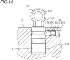
- a groove 35a that engages with the ball 39C is formed on the outer circumferential surface of the shaft portion 35A of the support member 35. Note however that the groove 35a is not always necessary and may be omitted.
- the ball 39C , the spring seat 39B and the spring 39A correspond to the "first contact portion", the "second contact portion” and the "elastic portion", respectively.
- the support member 35 can be secured inside the hole 37 by the ball plunger 39 simply by inserting the support member 35 into the hole 37. It is possible to prevent fretting wear, or the like, due to rising of the support member 35 while maintaining the ease of installment of the support member 35. It is possible to prevent the lowering of the connecting function of the rocker arm 40.
- the spring constant, etc., of the spring 39A By appropriately setting the spring constant, etc., of the spring 39A , the ease of operation of inserting the support member 35 into the hole 37 and the prevention of the rising of the support member 35 can be realized in a well-balanced manner. According to the present embodiment, there is no need to install the ball plunger 39 inside the support member 35 , and it is possible to increase the degree of freedom in the position of installment of the securing member.
- the securing member is a snap ring 139 fitted to the support member 35.
- a groove 35F is formed on the outer circumferential surface of the shaft portion 35A of the support member 35
- the snap ring 139 is fitted to the groove 35F.
- the groove 37a that engages with the snap ring 139 is formed on the inner circumferential surface of the hole 37 of the cylinder head 12. Note, however, that the groove 37a is not always necessary and may be omitted.
- the snap ring 139 When the shaft portion 35A of the support member 35 is inserted into the hole 37 of the cylinder head 12 , the snap ring 139 is pressed by the inner circumferential surface of the hole 37 so as to elastically deform radially inward. In other words, the radius of the snap ring 139 decreases.
- the support member 35 is pressed against the inner circumferential surface of the hole 37 with the snap ring 139 therebetween.
- the support member 35 is secured inside the hole 37.
- the securing member is the snap ring 139 , and therefore the securing member can be configured to be simple and compact.
- the snap ring 139 may be fitted to the inner circumferential surface of the hole 37 of the cylinder head 12 so that the snap ring 139 serves as the securing member for securing the support member 35.
- a groove 37F is formed on the inner circumferential surface of the hole 37
- the securing member is the snap ring 139 fitted into the groove 37F.
- the groove 35F that engages with the snap ring 139 is formed on the outer circumferential surface of the support member 35. Note, however, that the groove 35F is not always necessary and may be omitted.
- the snap ring 139 elastically deforms radially outward by being pressed by the outer circumferential surface of the support member 35. In other words, the radius of the snap ring 139 increases.
- the support member 35 is pressed against the inner circumferential surface of the hole 37 with the snap ring 139 therebetween.
- the support member 35 is secured inside the hole 37.
- the securing member is the snap ring 139 , and therefore the securing member can be configured to be simple and compact.
- the securing member is a ring-shaped coil spring 239 wound around the support member 35.
- the groove 35F is formed on the outer circumferential surface of the shaft portion 35A of the support member 35 , and the ring-shaped coil spring 239 is fitted to the groove 35F.
- the groove 37a that engages with the coil spring 239 is formed on the inner circumferential surface of the hole 37 of the cylinder head 12. Note, however, that the groove 37a is not always necessary and may be omitted.
- the ring-shaped coil spring 239 elastically deforms radially inward by being pressed by the inner circumferential surface of the hole 37.
- the support member 35 is pressed against the inner circumferential surface of the hole 37 with the coil spring 239 therebetween.
- the support member 35 is secured inside the hole 37.
- the securing member is the ring-shaped coil spring 239 , and therefore the securing member can be configured to be simple and compact.
- the ring-shaped coil spring 239 may be fitted to the inner circumferential surface of the hole 37 so that the coil spring 239 serves as the securing member for securing the support member 35.
- the groove 37F is formed on the inner circumferential surface of the hole 37
- the securing member is the ring-shaped coil spring 239 fitted to the groove 37F.
- the groove 35F that engages with the coil spring 239 is formed on the outer circumferential surface of the support member 35. Note, however, that the groove 35F is not always necessary and may be omitted.
- the ring-shaped coil spring 239 elastically deforms radially outward by being pressed by the outer circumferential surface of the support member 35.
- the support member 35 is pressed against the inner circumferential surface of the hole 37 with the coil spring 239 therebetween.
- the support member 35 is secured inside the hole 37.
- the securing member is the ring-shaped coil spring 239 , and therefore the securing member can be configured to be simple and compact.
- the securing member may be a leaf spring 339 secured to the edge of the hole 37 of the cylinder head 12.
- the leaf spring 339 is secured to the cylinder head 12 by a pin 340.
- the leaf spring 339 is formed with a hole 339d through which the support member 35 passes.
- the edge of the hole 339d of the leaf spring 339 is a first contact portion 339a that contacts the support member 35.
- a portion of the leaf spring 339 that is supported by the pin 340 is a second contact portion 339b that contacts the cylinder head 12 with the pin 340 therebetween.
- a portion between the first contact portion 339a and the second contact portion 339b is an elastic portion 339c.
- the securing member is the leaf spring 339 , and therefore the securing member can be configured to be simple.
- the first arm 41 is configured so as not to be in contact with the cam 21A , 23A.
- the valve 20 , 22 is brought to the inoperative state by switching the first arm 41 and the second arm 42 of the rocker arm 40 to the non-connected state.
- the first arm 41 may have a contact portion that contacts the cam 21A , 23A after the second arm 42 starts pivoting as the roller 43 is pushed by the cam 21A , 23A.
- it is possible to change the period in which the valve 20 , 22 is open For example, by elongating the period in which the valve 20 , 22 is open when the speed of the internal combustion engine 10 is high, it is possible to improve the performance at a high engine speed.
- the internal combustion engine 10 is a multi-cylinder engine.
- the internal combustion engine 10 may be a single-cylinder engine with which it is possible to change the timing with which the valve 20 , 22 is opened/closed.
- the internal combustion engine 10 includes a variable valve mechanism. That is, the rocker arm 40 includes the first arm 41 , and the second arm 42 pivotally supported on the first arm 41.
- the internal combustion engine 10 includes the connection switch pin 66 as a connecting mechanism that removably connects the first arm 41 and the second arm 42.
- the internal combustion engine 10 may not include a variable valve mechanism.
- the connecting mechanism may be omitted.
- the second arm 42 may be formed integral with the first arm 41 , and the rocker arm 40 may be a single-piece member.
- the internal combustion engine 10 may be unable to bring the valve 20 , 22 to the inoperative state, and may be configured unable to change the timing with which the valve 20 , 22 is opened/closed.
- the present invention includes any and all preferred embodiments including equivalent elements, modifications, omissions, combinations, adaptations and/or alterations as would be appreciated by those skilled in the art on the basis of the present disclosure.
- the limitations in the claims are to be interpreted broadly based on the language included in the claims and not limited to examples described in the present specification or during the prosecution of the application.
Landscapes
- Engineering & Computer Science (AREA)
- Mechanical Engineering (AREA)
- General Engineering & Computer Science (AREA)
- Valve-Gear Or Valve Arrangements (AREA)
- Valve Device For Special Equipments (AREA)
Abstract
Description
- The present invention relates to an internal combustion engine and a vehicle.
- There are conventional internal combustion engines that have a valve mechanism including: a circular columnar-shaped support member that is inserted into a hole formed in a cylinder head; a rocker arm that is pivotally supported on the support member; and a cam that is provided on a cam shaft and is in contact with the rocker arm. Patent Document No. 1 discloses a valve mechanism that includes a lash adjuster as the support member.
- Patent Document No. 1: Japanese Laid-Open Patent Publication No.
2009-185753 - In the valve mechanism, the rocker arm is held down by the cam. Therefore, the support member is held down by the cam with the rocker arm therebetween. However, the support member is only inserted into the hole of the cylinder head and is not particularly secured to the cylinder head. While the internal combustion engine is running, a load in the axial direction of the support member is repeatedly generated on the support member. Therefore, the support member may possibly rise from the hole, leading to problems such as fretting wear. On the other hand, if the support member is secured to the cylinder head using screws in order to prevent the rise, it will detract from the ease of installment of the support member.
- The present invention has been made in view of the above, and an object thereof is to provide an internal combustion engine that allows a support member to be installed easily while preventing fretting wear, or the like, due to rising of the support member, and a vehicle having the same.
- An internal combustion engine according to the present invention includes: a cylinder member formed with a hole; a port formed in the cylinder member; a valve installed in the cylinder member that opens/closes the port; a cam shaft rotatably supported on the cylinder member; a cam provided on the cam shaft; a columnar support member at least a portion of which is inserted into the hole of the cylinder member; a rocker arm that includes a supported portion pivotally supported on the support member, a pressed portion pressed by the cam, and an abutting portion to abut on the valve; and a securing member that secures the support member inside the hole. The securing member includes a first contact portion to be in contact with the support member, a second contact portion to be in contact with the cylinder member, and an elastic portion interposed between the first contact portion and the second contact portion.
- With the internal combustion engine described above, when the support member is pushed into the hole of the cylinder member, the support member is inserted into the hole. The support member is inserted into the hole and is then secured inside the hole by the elastic force of the elastic portion of the securing member. With the internal combustion engine described above, there is no need for an operation of securing the support member to the cylinder member by using screws. This makes the installment of the support member easy. Since the support member is secured by the elastic force of the elastic portion of the securing member, it is possible to prevent the support member from rising from the hole. Therefore, with the internal combustion engine described above, it is possible to prevent fretting wear, or the like, due to rising of the support member while maintaining the ease of installment of the support member.
- According to one preferred embodiment of the present invention, the securing member is a plunger mechanism that includes a spring arranged inside the support member, and a presser at least a portion of which is arranged outside the support member and that is connected to the spring.
- According to the embodiment described above, the securing member can be configured to be simple and compact. By appropriately setting the spring constant, etc., of the spring, the ease of operation of inserting the support member into the hole and the prevention of rising of the support member can be realized in a well-balanced manner.
- According to one preferred embodiment of the present invention, the securing member is a snap ring that is fitted to the support member.
- According to the embodiment described above, the securing member can be configured to be simple and compact.
- According to one preferred embodiment of the present invention, the securing member is a ring-shaped coil spring that is wound around the support member.
- According to the embodiment described above, the securing member can be configured to be simple and compact.
- According to one preferred embodiment of the present invention, a groove that engages with the securing member is formed on an inner surface of the hole of the cylinder member.
- According to the embodiment described above, when the support member is inserted into the hole of the cylinder member, the securing member engages with the groove, thus securing the support member inside the hole. As the securing member engages with the groove, the support member is even less likely to rise. Therefore, the ease of installment of the support member and the prevention of fretting wear, or the like, due to rising of the support member can be both realized at a high level.
- According to one preferred embodiment of the present invention, in a cross-section that passes through a part of the groove and that includes a center line of the hole, the groove has a sloped surface that is inclined relative to the center line of the hole so as to come closer to the center line of the hole while extending toward the rocker arm along a direction of the center line of the hole.
- According to the embodiment described above, the support member is even less likely to rise. Therefore, it is possible to even better prevent fretting wear, or the like, due to rising of the support member.
- According to one preferred embodiment of the present invention, the groove is a cone-shaped or circular columnar-shaped groove having an axis that is inclined relative to the center line of the hole.
- According to the embodiment described above, the groove can be machined by inserting a tool such as a drill or an endmill into the hole of the cylinder member from outside in a direction that is slanted relative to the center line of the hole. Therefore, the groove can be formed in a simple and inexpensive manner.
- According to one preferred embodiment of the present invention, the hole and the support member are each formed in a circular columnar shape. The groove is a circumferential groove formed on an inner circumferential surface of the hole.
- Where the groove is formed only at one point in the circumferential direction of the hole, if the position at which the groove is machined is shifted in the circumferential direction, the position at which the support member is attached in the circumferential direction may possibly be shifted. However, according to the embodiment described above, since the groove is formed in a circumferential pattern, the position at which the support member is attached in the circumferential direction is prevented from being shifted. Therefore, even if the machining precision of the groove is relatively low, it is possible to properly machine the groove. Thus, the groove can be formed in a simple and inexpensive manner.
- According to one preferred embodiment of the present invention, the securing member is a plunger mechanism that includes a spring arranged inside the cylinder member, and a presser at least a portion of which is arranged inside the hole of the cylinder member and that is connected to the spring.
- According to the embodiment described above, it is possible to increase the degree of freedom in the position of installing of the securing member. By appropriately setting the spring constant, etc., of the spring, the ease of operation of inserting the support member into the hole and the prevention of rising of the support member can be realized in a well-balanced manner.
- According to one preferred embodiment of the present invention, the securing member is a snap ring that is fitted to an inner surface of the hole of the cylinder member.
- According to the embodiment described above, the securing member can be configured to be simple and compact.
- According to one preferred embodiment of the present invention, the securing member is a ring-shaped coil spring that is fitted to an inner surface of the hole of the cylinder member.
- According to the embodiment described above, the securing member can be configured to be simple and compact.
- According to one preferred embodiment of the present invention, the securing member is a leaf spring that is secured to an edge of the hole of the cylinder member.
- According to the embodiment described above, the securing member can be configured to be simple.
- According to one preferred embodiment of the present invention, the rocker arm includes a first arm that includes the supported portion and the abutting portion, and a second arm that includes the pressed portion and is pivotally supported on the first arm. The internal combustion engine includes a connecting mechanism that removably connects the first arm and the second arm. The support member is configured to be unable to expand/contract in an axial direction of the support member.
- Where the rocker arm includes the second arm that is pivotally supported on the first arm, and the support member is a member that can contract/expand in the axial direction, such as a lash adjuster, the relative position between the first arm and the second arm may possibly be shifted following the expansion/contraction of the support member when the connection between the first arm and the second arm is disconnected. As a result, the second arm may be shifted from the intended position relative to the first arm, and the connecting mechanism may fail to properly connect the first arm and the second arm. However, according to the embodiment described above, since the support member is unable to expand/contract in the axial direction, it is possible to prevent the lowering of the connection function.
- A vehicle according to the present invention includes the internal combustion engine described above.
- Thus, it is possible to obtain a vehicle that realizes the advantageous effects described above.
- According to the present invention, it is possible to provide an internal combustion engine that allows easy installment of a support member that supports a rocker arm while preventing fretting wear, or the like, due to rising of the support member, and a vehicle having the same.
-
-
FIG. 1 is a view showing an example of an internal combustion engine according to one embodiment of the present invention installed in an automobile. -
FIG. 2 is a partial cross-sectional view of the internal combustion engine. -
FIG. 3 is a partial enlarged cross-sectional view of the internal combustion engine. -
FIG. 4 is a side view of a rocker arm and a support member. -
FIG. 5 is a plan view of the rocker arm and the support member. -
FIG. 6 is an exploded perspective view of a first arm and a second arm of the rocker arm. -
FIG. 7 is a cross-sectional view taken along line VII-VII ofFIG. 4 . -
FIG. 8 is equivalent toFIG. 7 , showing the rocker arm in the connected state. -
FIG. 9 is a side view showing the rocker arm in the connected state that has pivoted relative to the support member. -
FIG. 10 is equivalent toFIG. 7 , showing the rocker arm when the second arm pivots relative to the first arm. -
FIG. 11 is a side view showing the rocker arm and the support member when the second arm pivots relative to the first arm. -
FIG. 12A is a side view of a support member. -
FIG. 12B is a cross-sectional view taken along line XIIb-XIIb ofFIG. 12A . -
FIG. 13 is a cross-sectional view of a hole of a cylinder head. -
FIG. 14 is a side view of a support member according to an alternative embodiment. -
FIG. 15A is a cross-sectional view of a support member according to an alternative embodiment. -
FIG. 15B is a cross-sectional view taken along line XVb-XVb ofFIG. 15A . -
FIG. 16 is a cross-sectional view of a support member according to an alternative embodiment. -
FIG. 17A is a cross-sectional view of a support member according to an alternative embodiment. -
FIG. 17B is a cross-sectional view taken along line XVIIb-XVIIb ofFIG. 17A . -
FIG. 18 is a cross-sectional view of a support member according to an alternative embodiment. -
FIG. 19 is a side view of a support member according to an alternative embodiment. - An embodiment of the present invention will now be described with reference to the drawings. An internal combustion engine according to the present embodiment is installed in a vehicle and used as the drive source of the vehicle. There is no limitation on the type of the vehicle, which may be a straddled vehicle such as a motorcycle, an auto tricycle or an ATV (All Terrain Vehicle) or may be an automobile. For example, an
internal combustion engine 10 may be arranged in the engine room of anautomobile 5 as shown inFIG. 1 . - The
internal combustion engine 10 according to the present embodiment is a multi-cylinder engine having a plurality of cylinders. Theinternal combustion engine 10 is a 4-stroke engine that goes through the intake stroke, the compression stroke, the combustion stroke and the exhaust stroke.FIG. 2 is a partial cross-sectional view of theinternal combustion engine 10. As shown inFIG. 2 , theinternal combustion engine 10 includes a crankcase (not shown), acylinder body 7 connected to the crankcase, and acylinder head 12 connected to thecylinder body 7. A crankshaft (not shown) is arranged inside the crankcase. A plurality ofcylinders 6 are provided inside thecylinder body 7. Apiston 8 is arranged inside eachcylinder 6. Thepiston 8 and the crankshaft are connected by a connecting rod (not shown). - An
intake cam shaft 23 and anexhaust cam shaft 21 are rotatably supported on thecylinder head 12.Intake cams 23A are provided on theintake cam shaft 23, andexhaust cams 21A are provided on theexhaust cam shaft 21. -
Intake ports 16 andexhaust ports 14 are formed in thecylinder head 12. Anintake opening 18 is formed at one end of theintake port 16. Anexhaust opening 17 is formed on one end of theexhaust port 14. Theintake port 16 communicates with acombustion chamber 15 through theintake opening 18. Theexhaust port 14 communicates with thecombustion chamber 15 through theexhaust opening 17. Theintake port 16 serves to guide the mixed gas of the air and the fuel into thecombustion chamber 15. Theexhaust port 14 serves to guide the exhaust gas discharged from thecombustion chamber 15 to the outside. -
Intake valves 22 andexhaust valves 20 are installed in thecylinder head 12. Theintake valve 22 opens/closes theintake opening 18 of theintake port 16. Theexhaust valve 20 opens/closes theexhaust opening 17 of theexhaust port 14. Theintake valve 22 and theexhaust valve 20 are so-called poppet valves. Theintake valve 22 has ashaft portion 22a and anumbrella portion 22b, and theexhaust valve 20 has ashaft portion 20a and anumbrella portion 20b. The configuration of theintake valve 22 and the configuration of theexhaust valve 20 are similar to each other, and the configuration of theintake valve 22 will be described below while omitting the description of the configuration of theexhaust valve 20. Theshaft portion 22a of theintake valve 22 is slidably supported on thecylinder head 12 with a cylinder-shapedsleeve 24 therebetween. Avalve stem seal 25 is attached to one end of thesleeve 24 and theshaft portion 22a of theintake valve 22. Theshaft portion 22a of theintake valve 22 extends through thesleeve 24 and thevalve stem seal 25. Atappet 26 is fitted to the tip of theshaft portion 22a. - As shown in
FIG. 3 , acotter 28 is attached to theshaft portion 22a of theintake valve 22. Thecotter 28 is fitted to avalve spring retainer 30. Thevalve spring retainer 30 is secured to theintake valve 22 with thecotter 28 therebetween. Thevalve spring retainer 30 can move, together with theintake valve 22, in an axial direction of theintake valve 22. Theintake valve 22 extends through thevalve spring retainer 30. - The
internal combustion engine 10 includes avalve spring 32 that provides theintake valve 22 with a force in the direction of closing the intake opening 18 (the upward direction inFIG. 3 ). Thevalve spring 32 is a compression coil spring, and includes a firstspring end portion 32a supported on thevalve spring retainer 30 and a secondspring end portion 32b supported on thecylinder head 12. - The
internal combustion engine 10 includes arocker arm 40 that receives a force from theintake cam 23A to open/close theintake valve 22. Therocker arm 40 is pivotally supported on thecylinder head 12 with asupport member 35 therebetween.FIG. 4 is a side view of therocker arm 40 and thesupport member 35, andFIG. 5 is a plan view of therocker arm 40 and thesupport member 35. Therocker arm 40 includes afirst arm 41 and asecond arm 42 including aroller 43. -
FIG. 6 is an exploded perspective view of thefirst arm 41 and thesecond arm 42. Thefirst arm 41 includes aplate 41A, aplate 41B, anabutting plate 41C and a connectingplate 41D. Theplate 41A and theplate 41B are arranged parallel to each other. Theabutting plate 41C and the connectingplate 41D cross theplate 41A and theplate 41B. Theabutting plate 41C and the connectingplate 41D connect together theplate 41A and theplate 41B. Theplate 41A is formed with ahole 46A and ahole 48. Theplate 41B is formed with ahole 46B (seeFIG. 7 ) and thehole 48. Theholes FIG. 3 ). -
FIG. 7 is a cross-sectional view taken along line VII-VII ofFIG. 4 . As shown inFIG. 7 , a cylinder-shapedboss portion 49A is provided around thehole 46A of theplate 41A. A connectingpin 60A is slidably inserted inside thehole 46A. A bottomed cylinder-shapedcover portion 49B is provided around thehole 46B of theplate 41B. Thecover portion 49B is provided with ahole 47 having a smaller diameter than thehole 46B, but thehole 47 may be omitted. A connectingpin 60B is slidably inserted inside thehole 46B. Aspring 64 is arranged inside thehole 46B. Thespring 64 is present between thecover portion 49B and the connectingpin 60B, and urges the connectingpin 60B toward theplate 41A. - The
second arm 42 is arranged on the inner side of thefirst arm 41. That is, thesecond arm 42 is arranged between theplate 41A and theplate 41B. As shown inFIG. 6 thesecond arm 42 includes aplate 42A, aplate 42B, anabutting plate 42C and a connectingplate 42D. Theplate 42A and theplate 42B are arranged parallel to each other. Theabutting plate 42C and the connectingplate 42D cross theplate 42A and theplate 42B. Theabutting plate 42C and the connectingplate 42D connect together theplate 42A and theplate 42B. Theplate 42A and theplate 42B are formed with ahole 50 and ahole 52, respectively. - As shown in
FIG. 7 , the cylinder-shapedroller 43 is rotatably supported on thehole 50 of theplate 42A and thehole 50 of theplate 42B. Specifically, a cylinder-shapedcollar 54 is inserted through theholes 50 of theplate 42A and theplate 42B. Theroller 43 is rotatably supported on thecollar 54. A connectingpin 62 is slidably inserted inside thecollar 54. Since thecollar 54 is arranged inside theholes 50, the connectingpin 62 is slidably inserted inside theholes 50. Note that thecollar 54 is not always necessary. The connectingpin 62 may rotatably support theroller 43. - An outer diameter of the connecting
pin 60B is less than or equal to an inner diameter of thecollar 54. The connectingpin 60B is formed so that it can be inserted inside thecollar 54. An outer diameter of the connectingpin 62 is less than or equal to an inner diameter of thehole 46A. The connectingpin 62 is formed so that it can be inserted inside thehole 46A. In the present embodiment, the inner diameter of thecollar 54 and the inner diameter of thehole 46A are equal to each other. The outer diameter of the connectingpin 60B, the outer diameter of the connectingpin 62 and an outer diameter of the connectingpin 60A are equal to each other. - As shown in
FIG. 4 , thesupport member 35, thefirst arm 41 and thesecond arm 42 are connected together by asupport pin 56. Thesupport pin 56 is inserted through thehole 48 of theplate 41A and thehole 48 of theplate 41B of thefirst arm 41, and thehole 52 of theplate 42A and thehole 52 of theplate 42B of thesecond arm 42. Thefirst arm 41 and thesecond arm 42 are pivotally supported on thesupport member 35 by thesupport pin 56. Thesecond arm 42 is pivotally supported on thefirst arm 41 by thesupport pin 56. - As shown in
FIG. 7 , aconnection switch pin 66 is arranged on the side of therocker arm 40. Theconnection switch pin 66 is configured to be movable in the direction toward the connectingpin 60A and in the direction away from the connectingpin 60A. - As shown in
FIG. 8 , when theconnection switch pin 66 moves in the direction away from the connectingpin 60A, the connectingpins FIG. 8 due to the force of thespring 64. Thus, the connectingpin 60B is located inside thehole 46B and inside the hole 50 (specifically, inside the collar 54), and the connectingpin 62 is located inside the hole 50 (specifically, inside the collar 54) and inside thehole 46A. This state will hereinafter be referred to as the connected state. In the connected state, thefirst arm 41 and thesecond arm 42 are connected together by the connectingpin 60B and the connectingpin 62. As a result, as shown inFIG. 9 , thefirst arm 41 and thesecond arm 42 are, as a single unit, pivotable about the axis of the support pin 9. - As shown in
FIG. 7 , theconnection switch pin 66 moves toward the connectingpin 60A, the connectingpins connection switch pin 66 and slide rightward inFIG. 7 . Thus, the connectingpin 60B is located inside thehole 46B and not located inside thehole 50, and the connectingpin 62 is located inside thehole 50 and not located inside thehole 46A. This state will hereinafter be referred to as the non-connected state. In the non-connected state, as shown inFIG. 10 , the connectingpin 62 is slidable relative to the connectingpin 60A and the connectingpin 60B. As a result, as shown inFIG. 11 , thesecond arm 42 is pivotable about the axis of thesupport pin 56 relative to thefirst arm 41. Therefore, thesecond arm 42 pivots about the axis of thesupport pin 56 while thefirst arm 41 does not pivot. - As shown in
FIG. 3 , the portion of thefirst arm 41 that is supported by the support pin 56 (specifically, the portion of theplate 41A around thehole 48 and the portion of theplate 41B around the hole 48) forms a supportedportion 41S that is pivotally supported on thecylinder head 12. Theabutting plate 41C forms an "abutting portion" that is to abut on theintake valve 22 with thetappet 26 therebetween. Theroller 43 forms a "pressed portion" that is in contact with theintake cam 23A and is pressed by theintake cam 23A. - As shown in
FIG. 3 , thesupport member 35 that pivotally supports therocker arm 40 is inserted into ahole 37 formed in thecylinder head 12. In the present embodiment, thecylinder head 12 corresponds to the "cylinder member". Note, however, that a cam carrier (not shown) may be attached to thecylinder head 12, and thehole 37, through which thesupport member 35 is inserted, may be formed in the cam carrier. In such a case, thecylinder head 12 and the cam carrier, combined together, correspond to the "cylinder member". Thus, another member may be attached to thecylinder head 12, and thehole 37 may be formed in that member. In such a case, thecylinder head 12 and the other member, combined together, correspond to the "cylinder member". In the present embodiment, thesupport member 35 is formed in a circular columnar shape. Note however that thesupport member 35 is not limited to a circular columnar shape, but may be a polygonal columnar shape, for example, or any other columnar shape. Thehole 37 preferably has a cross-sectional shape that corresponds to the cross-sectional shape of thesupport member 35. -
FIG. 12A is a side view of thesupport member 35.FIG. 12B is a cross-sectional view taken along line XIIb-XIIb ofFIG. 12A . As shown inFIG. 12A , thesupport member 35 includes ashaft portion 35A at least a portion of which is inserted into thehole 37, and aring portion 35B formed with ahole 35C through which the support pin 56 (seeFIG. 3 ) is inserted. Aball plunger 39 is provided inside theshaft portion 35A as a securing member that secures thesupport member 35 in thehole 37. - As shown in
FIG. 12B , theshaft portion 35A of thesupport member 35 is formed with ahole 35D extending in the radial direction. Theball plunger 39 is fitted in thehole 35D. Theball plunger 39 includes aspring 39A that is a compression coil spring, aspring seat 39B that is connected to one end of thespring 39A, and aball 39C that is connected to the other end of thespring 39A. While theball 39C is an example of a presser of a plunger mechanism, the presser is not limited to theball 39C but may be a pin, etc. A portion of theball 39C is exposed on the outside of thehole 35D. The inner circumferential surface of thehole 37 of thecylinder head 12 is formed with agroove 37a that engages with theball 39C. - Although there is no limitation on the shape of the
groove 37a, thegroove 37a has a slopedsurface 37b as shown inFIG. 13 in the present embodiment. As shown inFIG. 13 , in a cross-section that passes through a part of thegroove 37a and that includes acenter line 37c of thehole 37, thesloped surface 37b is inclined relative to thecenter line 37c so as to come closer to thecenter line 37c while extending toward therocker arm 40 along the direction of thecenter line 37c of the hole 37 (i.e., upward inFIG. 13 ). - The
groove 37a is a cone-shaped or circular columnar-shaped groove having anaxis 13c that is inclined relative to thecenter line 37c of thehole 37. Thegroove 37a according to the present embodiment can be easily machined by inserting atool 13 such as a drill or an endmill into thehole 37 in a direction that is slanted relative to thecenter line 37c. - With the
internal combustion engine 10 according to the present embodiment, thesupport member 35 is not screwed onto thecylinder head 12. Thesupport member 35 can be easily attached to thecylinder head 12 by inserting thesupport member 35 into thehole 37. Specifically, by positioning theshaft portion 35A of thesupport member 35 above thehole 37 and inserting theshaft portion 35A into thehole 37, theball 39C is pushed by the inner circumferential surface of thehole 37, thus compressing thespring 39A. When theshaft portion 35A is inserted to a predetermined position, theball 39C engages with thegroove 37a. Then, the operator feels a clicking sensation and thus easily knows that theshaft portion 35A has been inserted to a predetermined position. Therefore, thesupport member 35 can be easily positioned, and thesupport member 35 is unlikely to come out of thehole 37. With the elastic force generated by the compression of thespring 39A, theball 39C is pressed against the inner circumferential surface of thehole 37. The pressure with which theball 39C presses the inner circumferential surface of thehole 37 secures thesupport member 35 inside thehole 37. - Note that in the present embodiment, the
spring seat 39B is an example of the first contact portion in contact with thesupport member 35. Theball 39C is an example of the second contact portion in contact with thecylinder head 12. Thespring 39A is present between thespring seat 39B and theball 39C, and is an example of the elastic portion. - As shown in
FIG. 3 , theinternal combustion engine 10 includes acompression coil spring 68, as a lost motion spring, that urges therocker arm 40 toward theintake cam 23A. Ashaft 70 that extends along a windingaxis 68d of thecompression coil spring 68 is arranged inside thecompression coil spring 68. Theshaft 70 has afirst end portion 70a, and asecond end portion 70b that is arranged on thesecond arm 42 side relative to thefirst end portion 70a. Aspring seat 72 that receives thecompression coil spring 68 is provided at thefirst end portion 70a. - The
compression coil spring 68 has afirst end portion 68a, and asecond end portion 68b that is arranged on thesecond arm 42 side relative to thefirst end portion 68a. Aretainer 74 is supported at thesecond end portion 68b. Theretainer 74 includes a disc-shapedtop plate portion 74a and a cylinder-shapedtube portion 74b. Thetube portion 74b extends from thetop plate portion 74a along the axial direction of theshaft 70 toward thecompression coil spring 68. Thetop plate portion 74a is supported on thesecond end portion 68b of thecompression coil spring 68. Thetop plate portion 74a is in contact with theabutting plate 42C of thesecond arm 42 of therocker arm 40. - The
spring seat 72, at least a portion of theshaft 70, at least a portion of thecompression coil spring 68 and at least a portion of thetube portion 74b of theretainer 74 are arranged inside ahole 76 formed in thecylinder head 12. - The
intake valve 22, thevalve spring 32, theshaft 70, theretainer 74, thecompression coil spring 68 and thesupport member 35 are arranged parallel to each other. Theretainer 74 is arranged between thevalve spring 32 and thesupport member 35. Theshaft 70 is arranged between thevalve spring 32 and thesupport member 35. - As shown in
FIG. 2 , as with theintake valve 22, thevalve spring 32, thevalve spring retainer 30, therocker arm 40, thesupport member 35, thecompression coil spring 68, etc., are provided also for theexhaust valve 20. These elements are similar to those described above, and will not be described in detail below. - With the
internal combustion engine 10 according to the present embodiment, it is possible to switch the operation state of theintake valve 22 and theexhaust valve 20 by switching the state of theconnection switch pin 66. - That is, when the
connection switch pin 66 is switched to the connected state, thefirst arm 41 and thesecond arm 42 of therocker arm 40 are connected together by the connectingpin 60B and the connecting pin 62 (seeFIG. 8 ). When theintake cam 23A pushes theroller 43 of therocker arm 40 following the rotation of theintake cam shaft 23, thefirst arm 41 and thesecond arm 42, as a single unit, pivot about the axis of the support pin 56 (seeFIG. 9 ). As a result, the abuttingplate 41C of thefirst arm 41 pushes theintake valve 22, thus opening theintake opening 18 of theintake port 16. Similarly, when theexhaust cam 21A pushes theroller 43 of therocker arm 40 following the rotation of theexhaust cam shaft 21, thefirst arm 41 and thesecond arm 42, as a single unit, pivot about the axis of thesupport pin 56. As a result, the abuttingplate 41C of thefirst arm 41 pushes theexhaust valve 20, thus opening theexhaust opening 17 of theexhaust port 14. - When the
connection switch pin 66 is switched to the non-connected state, the connection between thefirst arm 41 and thesecond arm 42 by the connectingpin 60B and the connectingpin 62 is disconnected (seeFIG. 7 ). Thesecond arm 42 becomes pivotable relative to the first arm 41 (seeFIG. 10 ). When theintake cam 23A pushes theroller 43 following the rotation of theintake cam shaft 23, thesecond arm 42 pivots about the axis of thesupport pin 56 while thefirst arm 41 does not pivot (seeFIG. 11 ). Therefore, the abuttingplate 41C of thefirst arm 41 will not push theintake valve 22, and theintake opening 18 remains closed by theintake valve 22. Similarly, when theexhaust cam 21A pushes theroller 43 following the rotation of theexhaust cam shaft 21, thesecond arm 42 pivots about the axis of thesupport pin 56 while thefirst arm 41 does not pivot. Therefore, the abuttingplate 41C of thefirst arm 41 will not push theexhaust valve 20, and theexhaust opening 17 remains closed by theexhaust valve 20. Thus, in the present embodiment, one or more of a plurality of cylinders can be brought to the inoperative state by switching theconnection switch pin 66 to the non-connected state. For example, by making one or more cylinders inoperative while the load is small, it is possible to improve the fuel efficiency. - As described above, with the
internal combustion engine 10 according to the present embodiment, thesupport member 35 that pivotally supports therocker arm 40 is not only inserted into thehole 37 of thecylinder head 12 but is also secured inside thehole 37 by theball plunger 39. While theinternal combustion engine 10 is running, thecam rocker arm 40, and a load in the axial direction is repeatedly generated on thesupport member 35. However, since thesupport member 35 is secured inside thehole 37 by theball plunger 39, it is possible to prevent thesupport member 35 from rising from thehole 37. Therefore, it is possible to prevent fretting wear, or the like, due to rising of thesupport member 35. - With the
internal combustion engine 10, when thesupport member 35 is pushed into thehole 37, thesupport member 35 is inserted into thehole 37 and is then secured inside thehole 37 by the elastic force of thespring 39A of theball plunger 39. With theinternal combustion engine 10 according to the present embodiment, there is no need for an operation of securing thesupport member 35 to thecylinder head 12 by using screws, bolts, or the like. This makes the installment of thesupport member 35 easy. - Thus, with the
internal combustion engine 10 according to the present embodiment, it is possible to prevent fretting wear, or the like, due to rising of thesupport member 35 while maintaining the ease of installment of thesupport member 35. - Now, where the
support member 35 is a member that can contract/expand in the axial direction, such as a lash adjuster, the position of therocker arm 40 changes following the contraction/expansion of thesupport member 35. For example, when thesupport member 35 expands, therocker arm 40 moves toward thecam FIG. 3 ). As a result, the position of the pivot center of thesecond arm 42 moves toward thecam cam roller 43 and thecam support member 35 expands when therocker arm 40 is in the non-connected state, thesecond arm 42 may not be able to return to the position where thehole 50 and thehole FIG. 7 ). Then, it is possible that thefirst arm 41 and thesecond arm 42 may not be properly connected together by the connectingpin 60B and the connectingpin 62, and the connecting function of therocker arm 40 may possibly lower. However, in the present embodiment, thesupport member 35, as opposed to a lash adjuster, cannot expand/contract in the axial direction. Therocker arm 40 does not move toward thecam first arm 41 and thesecond arm 42 of therocker arm 40. - Although there is no limitation on the securing member for securing the
support member 35 inside thehole 37 of thecylinder head 12, the present embodiment comprises theball plunger 39, which includes thespring 39A arranged inside thesupport member 35, and theball 39C at least a portion of which is arranged outside thesupport member 35. Therefore, the securing member can be configured to be simple and compact. By appropriately setting the spring constant, etc., of thespring 39A, the ease of operation of inserting thesupport member 35 into thehole 37 and the prevention of the rise of thesupport member 35 can be realized in a well-balanced manner. - With the
internal combustion engine 10 according to the present embodiment, thegroove 37a that engages with theball 39C of theball plunger 39 is formed on the inner circumferential surface of thehole 37 of thecylinder head 12. Thus, when thesupport member 35 is inserted into thehole 37, theball 39C engages with thegroove 37a, and thesupport member 35 is even less likely to rise. Therefore, the ease of installment of thesupport member 35 and the prevention of fretting wear, or the like, due to rising of thesupport member 35 can be both realized at a high level. - In the present embodiment, the
groove 37a has the slopedsurface 37b (seeFIG. 13 ). Since thegroove 37a has the slopedsurface 37b, theball 39C of theball plunger 39 is unlikely to come out of thegroove 37a, and thesupport member 35 is even less likely to rise. Therefore, it is possible to even better prevent fretting wear, or the like, due to rising of thesupport member 35. - In the present embodiment, the
groove 37a is a cone-shaped or circular columnar-shaped groove having theaxis 13c that is inclined relative to thecenter line 37c of thehole 37. According to the present embodiment, thegroove 37a can be machined by inserting thetool 13 such as a drill or an endmill into thehole 37 from outside thehole 37. Therefore, thegroove 37a can be formed in a simple and inexpensive manner. - Note that while the
groove 37a may be formed only at one point in the circumferential direction of thehole 37, it may be formed in a circumferential pattern (see the phantom line inFIG. 13 ). Where thegroove 37a is formed only at one point in the circumferential direction of thehole 37, if the position at which thegroove 37a is machined is shifted in the circumferential direction, the position at which thesupport member 35 is attached in the circumferential direction may possibly be shifted. However, where thegroove 37a is formed in a circumferential pattern, the position at which thesupport member 35 is attached in the circumferential direction is prevented from being shifted. Therefore, even if the machining precision of thegroove 37a is relatively low, it is possible to properly machine thegroove 37a. Thus, thegroove 37a can be formed in a simple and inexpensive manner. - While one embodiment of the present invention has been described above, it is needless to say that the present invention is not limited to this embodiment. Next, examples of alternative embodiments will be described. First, an example of an alternative embodiment employing a different configuration of the securing member will be described.
- With the
internal combustion engine 10 according to an alternative embodiment shown inFIG. 14 , the securing member is theball plunger 39 including thespring 39A and thespring seat 39B that are arranged inside thecylinder head 12, and theball 39C at least a portion of which is arranged inside thehole 37. Thespring 39A is a compression coil spring, wherein one end of thespring 39A is connected to thespring seat 39B and the other end thereof is connected to theball 39C. Agroove 35a that engages with theball 39C is formed on the outer circumferential surface of theshaft portion 35A of thesupport member 35. Note however that thegroove 35a is not always necessary and may be omitted. In the present embodiment, theball 39C, thespring seat 39B and thespring 39A correspond to the "first contact portion", the "second contact portion" and the "elastic portion", respectively. - Also in the present embodiment, the
support member 35 can be secured inside thehole 37 by theball plunger 39 simply by inserting thesupport member 35 into thehole 37. It is possible to prevent fretting wear, or the like, due to rising of thesupport member 35 while maintaining the ease of installment of thesupport member 35. It is possible to prevent the lowering of the connecting function of therocker arm 40. By appropriately setting the spring constant, etc., of thespring 39A, the ease of operation of inserting thesupport member 35 into thehole 37 and the prevention of the rising of thesupport member 35 can be realized in a well-balanced manner. According to the present embodiment, there is no need to install theball plunger 39 inside thesupport member 35, and it is possible to increase the degree of freedom in the position of installment of the securing member. - As shown in
FIG. 15A and FIG. 15B , with theinternal combustion engine 10 according to an alternative embodiment, the securing member is asnap ring 139 fitted to thesupport member 35. In the present embodiment, agroove 35F is formed on the outer circumferential surface of theshaft portion 35A of thesupport member 35, and thesnap ring 139 is fitted to thegroove 35F. Thegroove 37a that engages with thesnap ring 139 is formed on the inner circumferential surface of thehole 37 of thecylinder head 12. Note, however, that thegroove 37a is not always necessary and may be omitted. When theshaft portion 35A of thesupport member 35 is inserted into thehole 37 of thecylinder head 12, thesnap ring 139 is pressed by the inner circumferential surface of thehole 37 so as to elastically deform radially inward. In other words, the radius of thesnap ring 139 decreases. By the elastic force generated following the deformation of thesnap ring 139, thesupport member 35 is pressed against the inner circumferential surface of thehole 37 with thesnap ring 139 therebetween. Thus, thesupport member 35 is secured inside thehole 37. According to the present embodiment, the securing member is thesnap ring 139, and therefore the securing member can be configured to be simple and compact. - As shown in
FIG. 16 , thesnap ring 139 may be fitted to the inner circumferential surface of thehole 37 of thecylinder head 12 so that thesnap ring 139 serves as the securing member for securing thesupport member 35. In the present embodiment, agroove 37F is formed on the inner circumferential surface of thehole 37, and the securing member is thesnap ring 139 fitted into thegroove 37F. Thegroove 35F that engages with thesnap ring 139 is formed on the outer circumferential surface of thesupport member 35. Note, however, that thegroove 35F is not always necessary and may be omitted. In the present embodiment, when theshaft portion 35A of thesupport member 35 is inserted into thehole 37, thesnap ring 139 elastically deforms radially outward by being pressed by the outer circumferential surface of thesupport member 35. In other words, the radius of thesnap ring 139 increases. By the elastic force generated following the deformation of thesnap ring 139, thesupport member 35 is pressed against the inner circumferential surface of thehole 37 with thesnap ring 139 therebetween. Thus, thesupport member 35 is secured inside thehole 37. Also in the present embodiment, the securing member is thesnap ring 139, and therefore the securing member can be configured to be simple and compact. - As shown in
FIG. 17A and FIG. 17B , with theinternal combustion engine 10 according to an alternative embodiment, the securing member is a ring-shapedcoil spring 239 wound around thesupport member 35. In the present embodiment, thegroove 35F is formed on the outer circumferential surface of theshaft portion 35A of thesupport member 35, and the ring-shapedcoil spring 239 is fitted to thegroove 35F. Thegroove 37a that engages with thecoil spring 239 is formed on the inner circumferential surface of thehole 37 of thecylinder head 12. Note, however, that thegroove 37a is not always necessary and may be omitted. When theshaft portion 35A of thesupport member 35 is inserted into thehole 37, the ring-shapedcoil spring 239 elastically deforms radially inward by being pressed by the inner circumferential surface of thehole 37. By the elastic force generated following the deformation of thecoil spring 239, thesupport member 35 is pressed against the inner circumferential surface of thehole 37 with thecoil spring 239 therebetween. Thus, thesupport member 35 is secured inside thehole 37. According to the present embodiment, the securing member is the ring-shapedcoil spring 239, and therefore the securing member can be configured to be simple and compact. - As shown in
FIG. 18 , the ring-shapedcoil spring 239 may be fitted to the inner circumferential surface of thehole 37 so that thecoil spring 239 serves as the securing member for securing thesupport member 35. In the present embodiment, thegroove 37F is formed on the inner circumferential surface of thehole 37, and the securing member is the ring-shapedcoil spring 239 fitted to thegroove 37F. Thegroove 35F that engages with thecoil spring 239 is formed on the outer circumferential surface of thesupport member 35. Note, however, that thegroove 35F is not always necessary and may be omitted. In the present embodiment, when theshaft portion 35A of thesupport member 35 is inserted into thehole 37, the ring-shapedcoil spring 239 elastically deforms radially outward by being pressed by the outer circumferential surface of thesupport member 35. By the elastic force generated following the deformation of thecoil spring 239, thesupport member 35 is pressed against the inner circumferential surface of thehole 37 with thecoil spring 239 therebetween. Thus, thesupport member 35 is secured inside thehole 37. Also in the present embodiment, the securing member is the ring-shapedcoil spring 239, and therefore the securing member can be configured to be simple and compact. - As shown in
FIG. 19 , the securing member may be aleaf spring 339 secured to the edge of thehole 37 of thecylinder head 12. Herein, theleaf spring 339 is secured to thecylinder head 12 by apin 340. Theleaf spring 339 is formed with ahole 339d through which thesupport member 35 passes. The edge of thehole 339d of theleaf spring 339 is afirst contact portion 339a that contacts thesupport member 35. A portion of theleaf spring 339 that is supported by thepin 340 is a second contact portion 339b that contacts thecylinder head 12 with thepin 340 therebetween. A portion between thefirst contact portion 339a and the second contact portion 339b is an elastic portion 339c. According to the present embodiment, the securing member is theleaf spring 339, and therefore the securing member can be configured to be simple. - In the embodiment described above, the
first arm 41 is configured so as not to be in contact with thecam valve first arm 41 and thesecond arm 42 of therocker arm 40 to the non-connected state. However, thefirst arm 41 may have a contact portion that contacts thecam second arm 42 starts pivoting as theroller 43 is pushed by thecam valve first arm 41 and thesecond arm 42 to the non-connected state. Thus, it is possible to change the period in which thevalve valve internal combustion engine 10 is high, it is possible to improve the performance at a high engine speed. - In the embodiment described above, the
internal combustion engine 10 is a multi-cylinder engine. However, theinternal combustion engine 10 may be a single-cylinder engine with which it is possible to change the timing with which thevalve - In the embodiment described above, the
internal combustion engine 10 includes a variable valve mechanism. That is, therocker arm 40 includes thefirst arm 41, and thesecond arm 42 pivotally supported on thefirst arm 41. Theinternal combustion engine 10 includes theconnection switch pin 66 as a connecting mechanism that removably connects thefirst arm 41 and thesecond arm 42. However, theinternal combustion engine 10 may not include a variable valve mechanism. The connecting mechanism may be omitted. Thesecond arm 42 may be formed integral with thefirst arm 41, and therocker arm 40 may be a single-piece member. Theinternal combustion engine 10 may be unable to bring thevalve valve - The terms and expressions used herein are used for explanation purposes and should not be construed as being restrictive. It should be appreciated that the terms and expressions used herein do not eliminate any equivalents of features illustrated and mentioned herein, but include various modifications falling within the claimed scope of the present invention. The present invention may be embodied in many different forms. The present disclosure is to be considered as providing examples of the principles of the invention. These examples are described herein with the understanding that such examples are not intended to limit the present invention to preferred embodiments described herein and/or illustrated herein. Hence, the present invention is not limited to the preferred embodiments described herein. The present invention includes any and all preferred embodiments including equivalent elements, modifications, omissions, combinations, adaptations and/or alterations as would be appreciated by those skilled in the art on the basis of the present disclosure. The limitations in the claims are to be interpreted broadly based on the language included in the claims and not limited to examples described in the present specification or during the prosecution of the application.
- 5: Automobile (vehicle), 10: Internal combustion engine, 12: Cylinder head (cylinder member), 14: Exhaust port, 16: Intake port, 20: Exhaust valve, 21: Exhaust cam shaft, 21A: Exhaust cam, 22: Intake valve, 23: Intake cam shaft, 23A: Intake cam, 35: Support member, 37: Hole, 37a: Groove, 37b: Sloped surface, 39: Ball plunger (plunger mechanism), 39A: Spring, 39C: Ball (presser), 40: Rocker arm, 41: First arm, 41C: Abutting plate (abutting portion), 41S: Supported portion, 42: Second arm, 43: Roller (pressed portion), 66: Connection switch pin (connecting mechanism), 139: Snap ring, 239: Coil spring, 339: Leaf spring
Claims (14)
- An internal combustion engine comprising:a cylinder member formed with a hole;a port formed in the cylinder member;a valve that is installed in the cylinder member and that opens/closes the port;a cam shaft rotatably supported on the cylinder member;a cam provided on the cam shaft;a columnar support member at least a portion of which is inserted into the hole of the cylinder member;a rocker arm that includes a supported portion pivotally supported on the support member, a pressed portion pressed by the cam, and an abutting portion that abuts on the valve; anda securing member that includes a first contact portion that contacts the support member, a second contact portion that contacts the cylinder member, and an elastic portion interposed between the first contact portion and the second contact portion, wherein the securing member secures the support member inside the hole.
- The internal combustion engine according to claim 1, wherein the securing member is a plunger mechanism that includes a spring arranged inside the support member, and a presser at least a portion of which is arranged outside the support member and that is connected to the spring.
- The internal combustion engine according to claim 1, wherein the securing member is a snap ring that is fitted to the support member.
- The internal combustion engine according to claim 1, wherein the securing member is a ring-shaped coil spring that is wound around the support member.
- The internal combustion engine according to any one of claims 2 to 4, wherein a groove that engages with the securing member is formed on an inner surface of the hole of the cylinder member.
- The internal combustion engine according to claim 5, wherein in a cross-section that passes through a part of the groove and that includes a center line of the hole, the groove has a sloped surface that is inclined relative to the center line of the hole so as to come closer to the center line of the hole while extending toward the rocker arm along a direction of the center line of the hole.
- The internal combustion engine according to claim 5 or 6, wherein the groove is a cone-shaped or circular columnar-shaped groove having an axis that is inclined relative to the center line of the hole.
- The internal combustion engine according to any one of claims 5 to 7, wherein:the hole and the support member are each formed in a circular columnar shape; andthe groove is a circumferential groove formed on an inner circumferential surface of the hole.
- The internal combustion engine according to claim 1, wherein the securing member is a plunger mechanism that includes a spring arranged inside the cylinder member, and a presser at least a portion of which is arranged inside the hole of the cylinder member and that is connected to the spring.
- The internal combustion engine according to claim 1, wherein the securing member is a snap ring that is fitted to an inner surface of the hole of the cylinder member.
- The internal combustion engine according to claim 1, wherein the securing member is a ring-shaped coil spring that is fitted to an inner surface of the hole of the cylinder member.
- The internal combustion engine according to claim 1, wherein the securing member is a leaf spring that is secured to an edge of the hole of the cylinder member.
- The internal combustion engine according to any one of claims 1 to 12, wherein:the rocker arm includes a first arm that includes the supported portion and the abutting portion, and a second arm that includes the pressed portion and is pivotally connected to the first arm; anda connecting mechanism that removably connects the first arm and the second arm; andthe support member is configured to be unable to expand/contract in an axial direction of the support member.
- A vehicle comprising the internal combustion engine according to any one of claims 1 to 13.
Applications Claiming Priority (2)
| Application Number | Priority Date | Filing Date | Title |
|---|---|---|---|
| JP2017128790A JP6564817B2 (en) | 2017-06-30 | 2017-06-30 | Internal combustion engine and vehicle |
| PCT/JP2018/017283 WO2019003629A1 (en) | 2017-06-30 | 2018-04-27 | Internal combustion engine and vehicle |
Publications (3)
| Publication Number | Publication Date |
|---|---|
| EP3647555A1 true EP3647555A1 (en) | 2020-05-06 |
| EP3647555A4 EP3647555A4 (en) | 2020-06-24 |
| EP3647555B1 EP3647555B1 (en) | 2021-10-20 |
Family
ID=64742012
Family Applications (1)
| Application Number | Title | Priority Date | Filing Date |
|---|---|---|---|
| EP18824775.3A Active EP3647555B1 (en) | 2017-06-30 | 2018-04-27 | Internal combustion engine and vehicle |
Country Status (4)
| Country | Link |
|---|---|
| US (1) | US10851680B2 (en) |
| EP (1) | EP3647555B1 (en) |
| JP (1) | JP6564817B2 (en) |
| WO (1) | WO2019003629A1 (en) |
Family Cites Families (13)
| Publication number | Priority date | Publication date | Assignee | Title |
|---|---|---|---|---|
| FR1249387A (en) * | 1959-11-13 | 1960-12-30 | Renault | Improvements to the valve control of an overhead camshaft engine |
| US3217699A (en) * | 1964-04-20 | 1965-11-16 | Dolza John | Valve actuation mechanism |
| US4768467A (en) * | 1986-01-23 | 1988-09-06 | Fuji Jukogyo Kabushiki Kaisha | Valve operating system for an automotive engine |
| US5806477A (en) * | 1997-03-25 | 1998-09-15 | Chrysler Corporation | Quiet connector between rocker arm and valve stem |
| DE102007025182A1 (en) | 2007-05-30 | 2008-12-04 | Schaeffler Kg | Switchable cam follower for valve train of internal combustion engine, has two levers, which are mounted together in hinge bearing around axis of rotation in pivotably moving manner |
| JP5069140B2 (en) * | 2008-02-08 | 2012-11-07 | 株式会社オティックス | Variable valve mechanism |
| JP5757914B2 (en) * | 2012-05-21 | 2015-08-05 | 株式会社オティックス | Rocker arm with lash adjuster |
| JP2014005756A (en) | 2012-06-22 | 2014-01-16 | Hitachi Automotive Systems Ltd | Variable valve device of internal combustion engine |
| JP5951513B2 (en) * | 2013-01-21 | 2016-07-13 | 日立オートモティブシステムズ株式会社 | Variable valve operating device for multi-cylinder internal combustion engine and control device for the variable valve operating device |
| JP6258766B2 (en) * | 2014-04-23 | 2018-01-10 | 日立オートモティブシステムズ株式会社 | Variable valve operating device for internal combustion engine |
| US9624794B2 (en) | 2014-08-06 | 2017-04-18 | Schaeffler Technologies AG & Co. KG | Hydraulic lash adjuster anti-rotation clip |
| DE102015203049A1 (en) | 2015-02-20 | 2016-08-25 | Schaeffler Technologies AG & Co. KG | A clearance compensation device for a valve or tensioning device for a belt or chain drive |
| JP2017048734A (en) * | 2015-09-02 | 2017-03-09 | いすゞ自動車株式会社 | cylinder head |
-
2017
- 2017-06-30 JP JP2017128790A patent/JP6564817B2/en active Active
-
2018
- 2018-04-27 WO PCT/JP2018/017283 patent/WO2019003629A1/en not_active Ceased
- 2018-04-27 EP EP18824775.3A patent/EP3647555B1/en active Active
- 2018-04-27 US US16/627,138 patent/US10851680B2/en active Active
Also Published As
| Publication number | Publication date |
|---|---|
| WO2019003629A1 (en) | 2019-01-03 |
| EP3647555A4 (en) | 2020-06-24 |
| US20200182099A1 (en) | 2020-06-11 |
| US10851680B2 (en) | 2020-12-01 |
| JP2019011713A (en) | 2019-01-24 |
| JP6564817B2 (en) | 2019-08-21 |
| EP3647555B1 (en) | 2021-10-20 |
Similar Documents
| Publication | Publication Date | Title |
|---|---|---|
| EP2213849B1 (en) | Rocker arm retention | |
| US7980211B2 (en) | Cam follower for the variable actuation of a gas-exchange valve of an internal combustion engine | |
| EP0265191A1 (en) | Valve operating mechanism in an internal combustion engine | |
| US5239952A (en) | Valve actuating apparatus | |
| EP3647557B1 (en) | Internal combustion engine and vehicle | |
| US10066518B2 (en) | Variable valve mechanism for internal combustion engine | |
| EP3647555B1 (en) | Internal combustion engine and vehicle | |
| US9133766B2 (en) | Internal combustion engine | |
| JP2009138742A (en) | Valve operating system of variable displacement engine | |
| US6729282B2 (en) | Variable valve lift device | |
| US10519817B1 (en) | Switchable rocker arm with lash adjustment and travel stop | |
| US6880507B2 (en) | Internal combustion engine with switchable cam follower | |
| EP3647556B1 (en) | Valve spring retainer and internal combustion engine | |
| US11193401B2 (en) | Lost motion mechanism, valve gear and engine | |
| US7341034B2 (en) | Hydraulic tappet | |
| JP2002188418A (en) | Variable valve train for internal combustion engines | |
| US7467610B2 (en) | Valve-operating system for internal combustion engine | |
| JP3908952B2 (en) | Valve operating device for SOHC type internal combustion engine | |
| JP2006299880A (en) | Variable lift valve operating system for internal combustion engine | |
| JP2007231768A (en) | Oil passage for variable valve mechanism |
Legal Events
| Date | Code | Title | Description |
|---|---|---|---|
| STAA | Information on the status of an ep patent application or granted ep patent |
Free format text: STATUS: THE INTERNATIONAL PUBLICATION HAS BEEN MADE |
|
| PUAI | Public reference made under article 153(3) epc to a published international application that has entered the european phase |
Free format text: ORIGINAL CODE: 0009012 |
|
| STAA | Information on the status of an ep patent application or granted ep patent |
Free format text: STATUS: REQUEST FOR EXAMINATION WAS MADE |
|
| 17P | Request for examination filed |
Effective date: 20191223 |
|
| AK | Designated contracting states |
Kind code of ref document: A1 Designated state(s): AL AT BE BG CH CY CZ DE DK EE ES FI FR GB GR HR HU IE IS IT LI LT LU LV MC MK MT NL NO PL PT RO RS SE SI SK SM TR |
|
| A4 | Supplementary search report drawn up and despatched |
Effective date: 20200526 |
|
| RIC1 | Information provided on ipc code assigned before grant |
Ipc: F01L 1/18 20060101ALI20200519BHEP Ipc: F01L 1/46 20060101ALI20200519BHEP Ipc: F01L 1/20 20060101AFI20200519BHEP Ipc: F01L 13/00 20060101ALI20200519BHEP |
|
| GRAP | Despatch of communication of intention to grant a patent |
Free format text: ORIGINAL CODE: EPIDOSNIGR1 |
|
| STAA | Information on the status of an ep patent application or granted ep patent |
Free format text: STATUS: GRANT OF PATENT IS INTENDED |
|
| INTG | Intention to grant announced |
Effective date: 20210507 |
|
| GRAS | Grant fee paid |
Free format text: ORIGINAL CODE: EPIDOSNIGR3 |
|
| GRAA | (expected) grant |
Free format text: ORIGINAL CODE: 0009210 |
|
| STAA | Information on the status of an ep patent application or granted ep patent |
Free format text: STATUS: THE PATENT HAS BEEN GRANTED |
|
| AK | Designated contracting states |
Kind code of ref document: B1 Designated state(s): AL AT BE BG CH CY CZ DE DK EE ES FI FR GB GR HR HU IE IS IT LI LT LU LV MC MK MT NL NO PL PT RO RS SE SI SK SM TR |
|
| REG | Reference to a national code |
Ref country code: GB Ref legal event code: FG4D |
|
| REG | Reference to a national code |
Ref country code: CH Ref legal event code: EP |
|
| REG | Reference to a national code |
Ref country code: IE Ref legal event code: FG4D |
|
| REG | Reference to a national code |
Ref country code: DE Ref legal event code: R096 Ref document number: 602018025463 Country of ref document: DE |
|
| REG | Reference to a national code |
Ref country code: AT Ref legal event code: REF Ref document number: 1440128 Country of ref document: AT Kind code of ref document: T Effective date: 20211115 |
|
| REG | Reference to a national code |
Ref country code: LT Ref legal event code: MG9D |
|
| REG | Reference to a national code |
Ref country code: NL Ref legal event code: MP Effective date: 20211020 |
|
| REG | Reference to a national code |
Ref country code: AT Ref legal event code: MK05 Ref document number: 1440128 Country of ref document: AT Kind code of ref document: T Effective date: 20211020 |
|
| PG25 | Lapsed in a contracting state [announced via postgrant information from national office to epo] |
Ref country code: RS Free format text: LAPSE BECAUSE OF FAILURE TO SUBMIT A TRANSLATION OF THE DESCRIPTION OR TO PAY THE FEE WITHIN THE PRESCRIBED TIME-LIMIT Effective date: 20211020 Ref country code: LT Free format text: LAPSE BECAUSE OF FAILURE TO SUBMIT A TRANSLATION OF THE DESCRIPTION OR TO PAY THE FEE WITHIN THE PRESCRIBED TIME-LIMIT Effective date: 20211020 Ref country code: FI Free format text: LAPSE BECAUSE OF FAILURE TO SUBMIT A TRANSLATION OF THE DESCRIPTION OR TO PAY THE FEE WITHIN THE PRESCRIBED TIME-LIMIT Effective date: 20211020 Ref country code: BG Free format text: LAPSE BECAUSE OF FAILURE TO SUBMIT A TRANSLATION OF THE DESCRIPTION OR TO PAY THE FEE WITHIN THE PRESCRIBED TIME-LIMIT Effective date: 20220120 Ref country code: AT Free format text: LAPSE BECAUSE OF FAILURE TO SUBMIT A TRANSLATION OF THE DESCRIPTION OR TO PAY THE FEE WITHIN THE PRESCRIBED TIME-LIMIT Effective date: 20211020 |
|
| PG25 | Lapsed in a contracting state [announced via postgrant information from national office to epo] |
Ref country code: IS Free format text: LAPSE BECAUSE OF FAILURE TO SUBMIT A TRANSLATION OF THE DESCRIPTION OR TO PAY THE FEE WITHIN THE PRESCRIBED TIME-LIMIT Effective date: 20220220 Ref country code: SE Free format text: LAPSE BECAUSE OF FAILURE TO SUBMIT A TRANSLATION OF THE DESCRIPTION OR TO PAY THE FEE WITHIN THE PRESCRIBED TIME-LIMIT Effective date: 20211020 Ref country code: PT Free format text: LAPSE BECAUSE OF FAILURE TO SUBMIT A TRANSLATION OF THE DESCRIPTION OR TO PAY THE FEE WITHIN THE PRESCRIBED TIME-LIMIT Effective date: 20220221 Ref country code: PL Free format text: LAPSE BECAUSE OF FAILURE TO SUBMIT A TRANSLATION OF THE DESCRIPTION OR TO PAY THE FEE WITHIN THE PRESCRIBED TIME-LIMIT Effective date: 20211020 Ref country code: NO Free format text: LAPSE BECAUSE OF FAILURE TO SUBMIT A TRANSLATION OF THE DESCRIPTION OR TO PAY THE FEE WITHIN THE PRESCRIBED TIME-LIMIT Effective date: 20220120 Ref country code: NL Free format text: LAPSE BECAUSE OF FAILURE TO SUBMIT A TRANSLATION OF THE DESCRIPTION OR TO PAY THE FEE WITHIN THE PRESCRIBED TIME-LIMIT Effective date: 20211020 Ref country code: LV Free format text: LAPSE BECAUSE OF FAILURE TO SUBMIT A TRANSLATION OF THE DESCRIPTION OR TO PAY THE FEE WITHIN THE PRESCRIBED TIME-LIMIT Effective date: 20211020 Ref country code: HR Free format text: LAPSE BECAUSE OF FAILURE TO SUBMIT A TRANSLATION OF THE DESCRIPTION OR TO PAY THE FEE WITHIN THE PRESCRIBED TIME-LIMIT Effective date: 20211020 Ref country code: GR Free format text: LAPSE BECAUSE OF FAILURE TO SUBMIT A TRANSLATION OF THE DESCRIPTION OR TO PAY THE FEE WITHIN THE PRESCRIBED TIME-LIMIT Effective date: 20220121 Ref country code: ES Free format text: LAPSE BECAUSE OF FAILURE TO SUBMIT A TRANSLATION OF THE DESCRIPTION OR TO PAY THE FEE WITHIN THE PRESCRIBED TIME-LIMIT Effective date: 20211020 |
|
| REG | Reference to a national code |
Ref country code: DE Ref legal event code: R097 Ref document number: 602018025463 Country of ref document: DE |
|
| PG25 | Lapsed in a contracting state [announced via postgrant information from national office to epo] |
Ref country code: SM Free format text: LAPSE BECAUSE OF FAILURE TO SUBMIT A TRANSLATION OF THE DESCRIPTION OR TO PAY THE FEE WITHIN THE PRESCRIBED TIME-LIMIT Effective date: 20211020 Ref country code: SK Free format text: LAPSE BECAUSE OF FAILURE TO SUBMIT A TRANSLATION OF THE DESCRIPTION OR TO PAY THE FEE WITHIN THE PRESCRIBED TIME-LIMIT Effective date: 20211020 Ref country code: RO Free format text: LAPSE BECAUSE OF FAILURE TO SUBMIT A TRANSLATION OF THE DESCRIPTION OR TO PAY THE FEE WITHIN THE PRESCRIBED TIME-LIMIT Effective date: 20211020 Ref country code: EE Free format text: LAPSE BECAUSE OF FAILURE TO SUBMIT A TRANSLATION OF THE DESCRIPTION OR TO PAY THE FEE WITHIN THE PRESCRIBED TIME-LIMIT Effective date: 20211020 Ref country code: DK Free format text: LAPSE BECAUSE OF FAILURE TO SUBMIT A TRANSLATION OF THE DESCRIPTION OR TO PAY THE FEE WITHIN THE PRESCRIBED TIME-LIMIT Effective date: 20211020 Ref country code: CZ Free format text: LAPSE BECAUSE OF FAILURE TO SUBMIT A TRANSLATION OF THE DESCRIPTION OR TO PAY THE FEE WITHIN THE PRESCRIBED TIME-LIMIT Effective date: 20211020 |
|
| PLBE | No opposition filed within time limit |
Free format text: ORIGINAL CODE: 0009261 |
|
| STAA | Information on the status of an ep patent application or granted ep patent |
Free format text: STATUS: NO OPPOSITION FILED WITHIN TIME LIMIT |
|
| 26N | No opposition filed |
Effective date: 20220721 |
|
| PG25 | Lapsed in a contracting state [announced via postgrant information from national office to epo] |
Ref country code: AL Free format text: LAPSE BECAUSE OF FAILURE TO SUBMIT A TRANSLATION OF THE DESCRIPTION OR TO PAY THE FEE WITHIN THE PRESCRIBED TIME-LIMIT Effective date: 20211020 |
|
| PG25 | Lapsed in a contracting state [announced via postgrant information from national office to epo] |
Ref country code: SI Free format text: LAPSE BECAUSE OF FAILURE TO SUBMIT A TRANSLATION OF THE DESCRIPTION OR TO PAY THE FEE WITHIN THE PRESCRIBED TIME-LIMIT Effective date: 20211020 |
|
| REG | Reference to a national code |
Ref country code: CH Ref legal event code: PL |
|
| REG | Reference to a national code |
Ref country code: BE Ref legal event code: MM Effective date: 20220430 |
|
| PG25 | Lapsed in a contracting state [announced via postgrant information from national office to epo] |
Ref country code: MC Free format text: LAPSE BECAUSE OF FAILURE TO SUBMIT A TRANSLATION OF THE DESCRIPTION OR TO PAY THE FEE WITHIN THE PRESCRIBED TIME-LIMIT Effective date: 20211020 Ref country code: LU Free format text: LAPSE BECAUSE OF NON-PAYMENT OF DUE FEES Effective date: 20220427 Ref country code: LI Free format text: LAPSE BECAUSE OF NON-PAYMENT OF DUE FEES Effective date: 20220430 Ref country code: CH Free format text: LAPSE BECAUSE OF NON-PAYMENT OF DUE FEES Effective date: 20220430 |
|
| PG25 | Lapsed in a contracting state [announced via postgrant information from national office to epo] |
Ref country code: BE Free format text: LAPSE BECAUSE OF NON-PAYMENT OF DUE FEES Effective date: 20220430 |
|
| PG25 | Lapsed in a contracting state [announced via postgrant information from national office to epo] |
Ref country code: IE Free format text: LAPSE BECAUSE OF NON-PAYMENT OF DUE FEES Effective date: 20220427 |
|
| P01 | Opt-out of the competence of the unified patent court (upc) registered |
Effective date: 20230527 |
|
| PG25 | Lapsed in a contracting state [announced via postgrant information from national office to epo] |
Ref country code: MK Free format text: LAPSE BECAUSE OF FAILURE TO SUBMIT A TRANSLATION OF THE DESCRIPTION OR TO PAY THE FEE WITHIN THE PRESCRIBED TIME-LIMIT Effective date: 20211020 Ref country code: CY Free format text: LAPSE BECAUSE OF FAILURE TO SUBMIT A TRANSLATION OF THE DESCRIPTION OR TO PAY THE FEE WITHIN THE PRESCRIBED TIME-LIMIT Effective date: 20211020 |
|
| PG25 | Lapsed in a contracting state [announced via postgrant information from national office to epo] |
Ref country code: HU Free format text: LAPSE BECAUSE OF FAILURE TO SUBMIT A TRANSLATION OF THE DESCRIPTION OR TO PAY THE FEE WITHIN THE PRESCRIBED TIME-LIMIT; INVALID AB INITIO Effective date: 20180427 |
|
| PG25 | Lapsed in a contracting state [announced via postgrant information from national office to epo] |
Ref country code: MT Free format text: LAPSE BECAUSE OF FAILURE TO SUBMIT A TRANSLATION OF THE DESCRIPTION OR TO PAY THE FEE WITHIN THE PRESCRIBED TIME-LIMIT Effective date: 20211020 |
|
| PGFP | Annual fee paid to national office [announced via postgrant information from national office to epo] |
Ref country code: DE Payment date: 20250422 Year of fee payment: 8 |
|
| PGFP | Annual fee paid to national office [announced via postgrant information from national office to epo] |
Ref country code: IT Payment date: 20250424 Year of fee payment: 8 |
|
| PGFP | Annual fee paid to national office [announced via postgrant information from national office to epo] |
Ref country code: FR Payment date: 20250425 Year of fee payment: 8 |
|
| PG25 | Lapsed in a contracting state [announced via postgrant information from national office to epo] |
Ref country code: TR Free format text: LAPSE BECAUSE OF FAILURE TO SUBMIT A TRANSLATION OF THE DESCRIPTION OR TO PAY THE FEE WITHIN THE PRESCRIBED TIME-LIMIT Effective date: 20211020 |
|
| PGFP | Annual fee paid to national office [announced via postgrant information from national office to epo] |
Ref country code: GB Payment date: 20260306 Year of fee payment: 9 |