EP3647543B1 - Procédé de conception d'un moteur à turbine à gaz et moteur à turbine à gaz associé - Google Patents
Procédé de conception d'un moteur à turbine à gaz et moteur à turbine à gaz associé Download PDFInfo
- Publication number
- EP3647543B1 EP3647543B1 EP19205990.5A EP19205990A EP3647543B1 EP 3647543 B1 EP3647543 B1 EP 3647543B1 EP 19205990 A EP19205990 A EP 19205990A EP 3647543 B1 EP3647543 B1 EP 3647543B1
- Authority
- EP
- European Patent Office
- Prior art keywords
- aft
- purge openings
- cavity
- stage
- purge
- Prior art date
- Legal status (The legal status is an assumption and is not a legal conclusion. Google has not performed a legal analysis and makes no representation as to the accuracy of the status listed.)
- Active
Links
- 238000000034 method Methods 0.000 title claims description 13
- 238000010926 purge Methods 0.000 claims description 73
- 239000007789 gas Substances 0.000 claims description 55
- 238000004891 communication Methods 0.000 claims description 10
- 239000012530 fluid Substances 0.000 claims description 9
- 230000004888 barrier function Effects 0.000 claims description 6
- 238000001816 cooling Methods 0.000 claims description 6
- 230000003068 static effect Effects 0.000 claims description 6
- 238000007789 sealing Methods 0.000 description 19
- 230000037406 food intake Effects 0.000 description 8
- 239000000446 fuel Substances 0.000 description 7
- 230000009467 reduction Effects 0.000 description 4
- 230000008901 benefit Effects 0.000 description 3
- 230000007797 corrosion Effects 0.000 description 3
- 238000005260 corrosion Methods 0.000 description 3
- 238000013459 approach Methods 0.000 description 2
- 238000002485 combustion reaction Methods 0.000 description 2
- 230000008859 change Effects 0.000 description 1
- 230000006835 compression Effects 0.000 description 1
- 238000007906 compression Methods 0.000 description 1
- 238000012937 correction Methods 0.000 description 1
- 230000001419 dependent effect Effects 0.000 description 1
- 238000013461 design Methods 0.000 description 1
- 239000003112 inhibitor Substances 0.000 description 1
- 230000007246 mechanism Effects 0.000 description 1
- 230000004044 response Effects 0.000 description 1
- 230000035945 sensitivity Effects 0.000 description 1
- 230000007704 transition Effects 0.000 description 1
- 238000011144 upstream manufacturing Methods 0.000 description 1
Images


Classifications
-
- F—MECHANICAL ENGINEERING; LIGHTING; HEATING; WEAPONS; BLASTING
- F02—COMBUSTION ENGINES; HOT-GAS OR COMBUSTION-PRODUCT ENGINE PLANTS
- F02C—GAS-TURBINE PLANTS; AIR INTAKES FOR JET-PROPULSION PLANTS; CONTROLLING FUEL SUPPLY IN AIR-BREATHING JET-PROPULSION PLANTS
- F02C7/00—Features, components parts, details or accessories, not provided for in, or of interest apart form groups F02C1/00 - F02C6/00; Air intakes for jet-propulsion plants
- F02C7/12—Cooling of plants
- F02C7/16—Cooling of plants characterised by cooling medium
- F02C7/18—Cooling of plants characterised by cooling medium the medium being gaseous, e.g. air
-
- F—MECHANICAL ENGINEERING; LIGHTING; HEATING; WEAPONS; BLASTING
- F01—MACHINES OR ENGINES IN GENERAL; ENGINE PLANTS IN GENERAL; STEAM ENGINES
- F01D—NON-POSITIVE DISPLACEMENT MACHINES OR ENGINES, e.g. STEAM TURBINES
- F01D5/00—Blades; Blade-carrying members; Heating, heat-insulating, cooling or antivibration means on the blades or the members
- F01D5/02—Blade-carrying members, e.g. rotors
- F01D5/08—Heating, heat-insulating or cooling means
- F01D5/081—Cooling fluid being directed on the side of the rotor disc or at the roots of the blades
- F01D5/082—Cooling fluid being directed on the side of the rotor disc or at the roots of the blades on the side of the rotor disc
-
- F—MECHANICAL ENGINEERING; LIGHTING; HEATING; WEAPONS; BLASTING
- F01—MACHINES OR ENGINES IN GENERAL; ENGINE PLANTS IN GENERAL; STEAM ENGINES
- F01D—NON-POSITIVE DISPLACEMENT MACHINES OR ENGINES, e.g. STEAM TURBINES
- F01D11/00—Preventing or minimising internal leakage of working-fluid, e.g. between stages
- F01D11/001—Preventing or minimising internal leakage of working-fluid, e.g. between stages for sealing space between stator blade and rotor
-
- F—MECHANICAL ENGINEERING; LIGHTING; HEATING; WEAPONS; BLASTING
- F01—MACHINES OR ENGINES IN GENERAL; ENGINE PLANTS IN GENERAL; STEAM ENGINES
- F01D—NON-POSITIVE DISPLACEMENT MACHINES OR ENGINES, e.g. STEAM TURBINES
- F01D11/00—Preventing or minimising internal leakage of working-fluid, e.g. between stages
- F01D11/02—Preventing or minimising internal leakage of working-fluid, e.g. between stages by non-contact sealings, e.g. of labyrinth type
- F01D11/04—Preventing or minimising internal leakage of working-fluid, e.g. between stages by non-contact sealings, e.g. of labyrinth type using sealing fluid, e.g. steam
-
- F—MECHANICAL ENGINEERING; LIGHTING; HEATING; WEAPONS; BLASTING
- F05—INDEXING SCHEMES RELATING TO ENGINES OR PUMPS IN VARIOUS SUBCLASSES OF CLASSES F01-F04
- F05D—INDEXING SCHEME FOR ASPECTS RELATING TO NON-POSITIVE-DISPLACEMENT MACHINES OR ENGINES, GAS-TURBINES OR JET-PROPULSION PLANTS
- F05D2220/00—Application
- F05D2220/30—Application in turbines
- F05D2220/32—Application in turbines in gas turbines
- F05D2220/321—Application in turbines in gas turbines for a special turbine stage
- F05D2220/3212—Application in turbines in gas turbines for a special turbine stage the first stage of a turbine
-
- F—MECHANICAL ENGINEERING; LIGHTING; HEATING; WEAPONS; BLASTING
- F05—INDEXING SCHEMES RELATING TO ENGINES OR PUMPS IN VARIOUS SUBCLASSES OF CLASSES F01-F04
- F05D—INDEXING SCHEME FOR ASPECTS RELATING TO NON-POSITIVE-DISPLACEMENT MACHINES OR ENGINES, GAS-TURBINES OR JET-PROPULSION PLANTS
- F05D2260/00—Function
- F05D2260/20—Heat transfer, e.g. cooling
- F05D2260/201—Heat transfer, e.g. cooling by impingement of a fluid
-
- Y—GENERAL TAGGING OF NEW TECHNOLOGICAL DEVELOPMENTS; GENERAL TAGGING OF CROSS-SECTIONAL TECHNOLOGIES SPANNING OVER SEVERAL SECTIONS OF THE IPC; TECHNICAL SUBJECTS COVERED BY FORMER USPC CROSS-REFERENCE ART COLLECTIONS [XRACs] AND DIGESTS
- Y02—TECHNOLOGIES OR APPLICATIONS FOR MITIGATION OR ADAPTATION AGAINST CLIMATE CHANGE
- Y02T—CLIMATE CHANGE MITIGATION TECHNOLOGIES RELATED TO TRANSPORTATION
- Y02T50/00—Aeronautics or air transport
- Y02T50/60—Efficient propulsion technologies, e.g. for aircraft
Definitions
- the present invention relates to a method of designing a gas turbine engine as well as to a corresponding gas turbine engine.
- a gas turbine engine typically includes a fan section, a compressor section, a combustor section, and a turbine section. Air entering the compressor section is compressed and delivered into the combustion section where it is mixed with fuel and ignited to generate a high-speed exhaust gas flow. The high-speed exhaust gas flow expands through the turbine section to drive the compressor and the fan section.
- Hot gases in the area of the turbine can move radially inward into an inner cavity.
- the occurrence of hot gases entering the inner cavity is generally referred to as ingestion and is undesirable.
- Ingestion of hot gases into the inner cavity can lead to increased corrosion of components in the inner cavity.
- Purge air is directed into the inner cavity at an interface between the turbine rotor and an associated transition housing to resist this flow of hot gas. Utilizing large amounts of purge air can lead to lower component efficiencies and higher thrust specific fuel consumption. This leads to higher fuel consumption for any given flight condition.
- uncaptured purge air can result in higher combustion exit temperatures and potentially reduce turbine component life. Therefore, it is desirable to reduce the amount of purge air needed to resist the ingestion of hot gases into the inner cavity.
- US 6 481 959 B1 discloses a gas turbine engine disk cavity ingestion inhibitor
- US 5 157 914 A discloses modulated gas turbine engine cooling air
- US 6 065 928 A discloses a turbine nozzle having a purged air circuit
- EP 2 474 708 A2 discloses an interstage seal for a gas turbine engine
- US 2016/312631 A1 discloses multiple injector holes for a gas turbine engine vane.
- FIG. 1 schematically illustrates a gas turbine engine 20.
- the gas turbine engine 20 is disclosed herein as a two-spool turbofan that generally incorporates a fan section 22, a compressor section 24, a combustor section 26 and a turbine section 28.
- the fan section 22 drives air along a bypass flow path B in a bypass duct defined within a fan case 15 or nacelle, and also drives air along a core flow path C for compression and communication into the combustor section 26 then expansion through the turbine section 28.
- FIG. 1 schematically illustrates a gas turbine engine 20.
- the gas turbine engine 20 is disclosed herein as a two-spool turbofan that generally incorporates a fan section 22, a compressor section 24, a combustor section 26 and a turbine section 28.
- the fan section 22 drives air along a bypass flow path B in a bypass duct defined within a fan case 15 or nacelle, and also drives air along a core flow path C for compression and communication into the combustor section 26 then expansion through the turbine section
- the exemplary engine 20 generally includes a low speed spool 30 and a high speed spool 32 mounted for rotation about an engine central longitudinal axis A relative to an engine static structure 36 via several bearing systems 38. It should be understood that various bearing systems 38 at various locations may alternatively or additionally be provided, and the location of bearing systems 38 may be varied as appropriate to the application.
- the low speed spool 30 generally includes an inner shaft 40 that interconnects, a first (or low) pressure compressor 44 and a first (or low) pressure turbine 46.
- the inner shaft 40 is connected to the fan 42 through a speed change mechanism, which in exemplary gas turbine engine 20 is illustrated as a geared architecture 48 to drive a fan 42 at a lower speed than the low speed spool 30.
- the high speed spool 32 includes an outer shaft 50 that interconnects a second (or high) pressure compressor 52 and a second (or high) pressure turbine 54.
- a combustor 56 is arranged in exemplary gas turbine 20 between the high pressure compressor 52 and the high pressure turbine 54.
- a mid-turbine frame 57 of the engine static structure 36 may be arranged generally between the high pressure turbine 54 and the low pressure turbine 46.
- the mid-turbine frame 57 further supports bearing systems 38 in the turbine section 28.
- the inner shaft 40 and the outer shaft 50 are concentric and rotate via bearing systems 38 about the engine central longitudinal axis A which is colline
- the core airflow is compressed by the low pressure compressor 44 then the high pressure compressor 52, mixed and burned with fuel in the combustor 56, then expanded over the high pressure turbine 54 and low pressure turbine 46.
- the mid-turbine frame 57 includes airfoils 59 which are in the core airflow path C.
- the turbines 46, 54 rotationally drive the respective low speed spool 30 and high speed spool 32 in response to the expansion.
- gear system 48 may be located aft of the low pressure compressor, or aft of the combustor section 26 or even aft of turbine section 28, and fan 42 may be positioned forward or aft of the location of gear system 48.
- the engine 20 in one example is a high-bypass geared aircraft engine.
- the engine 20 bypass ratio is greater than about six (6), with an example embodiment being greater than about ten (10)
- the geared architecture 48 is an epicyclic gear train, such as a planetary gear system or other gear system, with a gear reduction ratio of greater than about 2.3
- the low pressure turbine 46 has a pressure ratio that is greater than about five.
- the engine 20 bypass ratio is greater than about ten (10:1)
- the fan diameter is significantly larger than that of the low pressure compressor 44
- the low pressure turbine 46 has a pressure ratio that is greater than about five 5:1.
- Low pressure turbine 46 pressure ratio is pressure measured prior to inlet of low pressure turbine 46 as related to the pressure at the outlet of the low pressure turbine 46 prior to an exhaust nozzle.
- the geared architecture 48 may be an epicycle gear train, such as a planetary gear system or other gear system, with a gear reduction ratio of greater than about 2.3:1 and less than about 5:1. It should be understood, however, that the above parameters are only exemplary of one embodiment of a geared architecture engine and that the present invention is applicable to other gas turbine engines including direct drive turbofans.
- the fan section 22 of the engine 20 is designed for a particular flight condition - - typically cruise at about 0.8 Mach and about 35,000 feet (10,668 meters).
- the flight condition of 0.8 Mach and 35,000 ft (10,668 meters), with the engine at its best fuel consumption - also known as "bucket cruise Thrust Specific Fuel Consumption ('TSFC')" - is the industry standard parameter of lbm of fuel being burned divided by lbf of thrust the engine produces at that minimum point.
- "Low fan pressure ratio” is the pressure ratio across the fan blade alone, without a Fan Exit Guide Vane (“FEGV”) system.
- the low fan pressure ratio as disclosed herein according to one non-limiting embodiment is less than about 1.45.
- Low corrected fan tip speed is the actual fan tip speed in ft/sec divided by an industry standard temperature correction of [(Tram °R) / (518.7 °R)] 0.5 .
- the "Low corrected fan tip speed” as disclosed herein according to one non-limiting embodiment is less than about 1150 ft / second (350.5 meters/second).
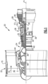
- FIG. 2 illustrates an enlarged schematic view of the high pressure turbine 54, however, other sections of the gas turbine engine 20 could benefit from this disclosure, such as the low pressure turbine 46 or the compressor section 24.
- the high pressure turbine 54 is a two-stage turbine with a first rotor assembly 60 and a second rotor assembly 62.
- this disclosure also applies to high pressure turbines 54 with only a one-stage turbine or low pressure turbines 46 with a turbine having more than two stages.
- the first rotor assembly 60 includes first rotor blades 64 that form an array of circumferentially spaced blades around a first disk 68 and the second rotor assembly 62 includes second rotor blades 66 that form an array of circumferentially spaced blades around a second disk 70.
- the first and second rotor blades 64, 66 include a respective first root portion 72 and a second root portion 74, a first platform 76 and a second platform 78, and a first airfoil 80 and a second airfoil 82.
- Each of the first and second root portions 72, 74 is received within respective first and second rims 84, 86 of the first and second disks 68, 70.
- the first airfoil 80 and the second airfoil 82 extend radially outward toward a first and second blade outer air seal (BOAS) assembly 81, 83, respectively.
- BOAS blade outer air seal
- the first and second rotor blades 64, 66 are disposed in the core airflow path C that is pressurized in the compressor section 24 then heated to a working temperature in the combustor section 26.
- the first and second platforms 76, 78 separate a gas path side inclusive of the first and second airfoils 80, 82 and a non-gas path side inclusive of the respective first and second root portions 72, 74.
- a first vane assembly 90 is located axially upstream of the first rotor assembly 60 and is fixed relative to the engine static structure 36.
- the first vane assembly 90 includes vanes 92 that form a circumferential array.
- the vanes 92 each include an airfoil 94 that extends between a respective inner vane platform 96 and an outer vane platform 98.
- the outer vane platform 98 may at least partially engage the first BOAS 81 and the inner vane platform 96 cooperates with the first platform 76 to direct the hot exhaust gases along the core airflow path C.
- a second vane assembly 100 is also located secured to the engine case structure 36 and located between the first rotor assembly 60 and the second rotor assembly 62.
- the second vane assembly 100 directs the hot exhaust gases along the core airflow path C from the first rotor blades 64 to the second rotor blades 66.
- the second vane assembly 100 includes vanes 102 that from a circumferential array.
- the vanes 102 include an airfoil 104 that extends between a respective inner vane platform 106 and an outer vane platform 108.
- the outer vane platform 108 may at least partially engage the first BOAS 81 and the second BOAS 83 while the inner vane platform 106 cooperates with the first platform 76 and the second platform 78 to direct the hot exhaust gases along the core airflow path C.
- This disclose also applies to ingestion in other downstream forward and aft cavities for other stages in a similar manner as described with respect to the first stage forward cavity 110 and first stage aft cavity 112.
- the first stage forward cavity 110 is located downstream of the first vane assembly 90 and is bounded by the first vane assembly 90, first rotor assembly 60, and a first stage forward cover plate 114.
- the first stage aft cavity 112 is located downstream of the first rotor assembly 60 and is bounded by the first rotor assembly 60, a first stage aft cover plate 116, and the second vane assembly 100.
- the hot exhaust gases can enter the first stage forward cavity 110 as indicated above.
- bleed air A from the compressor section 24 is directed into the first stage forward cavity 110 through a plurality of purge openings 118.
- the purge openings 118 are circumferentially spaced around the static structure 36 in order to direct the bleed air A into the first stage forward cavity 110.
- the purge opening 118 could be located in the first vane assembly 90 and be in fluid communication with the first stage forward cavity 110.
- the number and/or cross-sectional area of the purge openings 118 can be varied in order to achieve a desired mass flow rate of bleed air A into the first stage forward cavity 110.
- the purge openings 118 could be circular or slotted.
- the purge openings 118 could extend in a direction that is transverse to the engine axis A and include a first set of purge openings 118 extending towards the engine axis A and a second set of purge openings 118 extending away from the engine axis A.
- the purge openings 118 could also extend in a direction having a component directed in a circumferential direction, such as with or against the direction of rotation of the first rotor assembly 60.
- a radial location of the purge openings 118 contributes to adequately cooling specific components adjacent the first stage forward cavity 110 as described further below.
- Figure 3 is an enlarged view of the first stage forward cavity 110.
- the radial position of the purge openings 118 is measured to a center line CL of each of the purge opening 118.
- the purge openings 118 could be non-circular in cross section and another identifying location on the purge openings 118 could be used as long as the position measured is consistent between purge openings 118.
- the center line CL of the purge openings 118 creates a division in the first stage forward cavity 110 between a radially inner portion 110A and a radially outer portion 110B.
- the purge openings 118 create an air barrier that separates the radially inner portion 110A with low ingestion from the radially outer portion 110B with higher ingestion.
- the purge openings 118 are aligned with the top of the first disk 68 to create an air barrier that is radially aligned with the top of the first disk 68.
- the radial location of purge openings 118 contributes to a variation in sealing effectiveness of the first stage forward cavity 110 between the radially inner portion 110A and the radially outer portion 110B.
- the sealing effectiveness in the first stage forward cavity 110 is a ratio of the hot exhaust gases from the core airflow path C compared to bleed air A that enters the first stage forward cavity 110.
- a sealing effectiveness of zero indicates that the rim cavity is entirely fill with air ingested from the gas path and a sealing effectiveness of 1 indicates that the rim cavity is entirely filled with air from a secondary source, such as purge air.
- the radially inner portion 110A requires a lower mass flow rate of bleed air A compared to the sealing effectives of the radially outer portion 110B at the same mass flow rate of bleed air A through the purge openings 118.
- the variation of sealing effectiveness is represented graphically in Figures 4 and 5 .
- Figure 4 illustrates the sealing effectiveness of the radially inner portion 110A on the vertical axis and a non-dimensionalized flow rate of bleed air A on the horizontal axis.
- a margin of error for sealing effectiveness is shown in dashed lines above and below the solid line representing the sealing effectiveness within the margin of error.
- the non-dimensionalized flow rate is calculated by dividing the mass flow rate of bleed air A ( ⁇ purge) entering the first stage forward cavity 110 through the purge openings 118 by the minimum mass flow rate of bleed air A ( ⁇ min) needed to achieve a complete sealing effectiveness (equal to 1) across the entire first stage forward cavity 110.
- Figure 5 illustrates the same relationship described above in Figure 4 , but with respect to the radially outer portion 110B of the first stage forward cavity 110.
- the sealing effectiveness achieved at lower non-dimensionalized flow rates is greater in the radially inner portion 110A than compared to the radially outer portion 110B.
- the radially inner portion 110A includes a sealing effectiveness of approximately 0.70 to 0.80 while the radially outer portion 110B includes a sealing effectiveness of approximately 0.40 to 0.50.
- the sealing effectiveness also approaches 1.
- the variation in sealing effectiveness between the radially inner portion 110A and the radially outer portion 110B, allows for reductions in bleed air A needed to purge the first stage forward cavity 110.
- the reduction in bleed air A results in greater efficiency of the gas turbine engine 20 by allowing a greater percentage of air compressed in the compressor section 24 to be directed to the combustor section 26.
- certain portions of the first vane assembly 90 and the first rotor assembly 60 have a greater sensitivity to hot exhaust gases and therefore require more bleed air A to purge the first stage forward cavity 110.
- the bleed air A needed to cool these components can be reduced.
- the first disk 68 and the cover plate 114 are more susceptible to damage and/or corrosion from the hot exhaust gases in the core airflow path C than the root portion 72 of the blade 64. Therefore, selecting a radial location for the purge openings 118 that is radially outward or at least radially aligned with the more sensitive components can reduce the amount of bleed air A needed for purging the first stage forward cavity 110.
- bleed air A is directed radially inward through the vanes 102 and reaches aft purge openings 120 in the vanes 102 ( Figure 2 ).
- a radially inner portion 112A ( Figure 2 ) of the first stage aft cavity 112 includes the aft cover plate 116 and the first disk 68, which are more susceptible to damage and/or corrosion by the hot exhaust gases from the core airflow path C.
- a radially outer portion 112B ( Figure 2 ) of the first stage aft cavity 112 includes the root portion 72 of the blade 64, which can sustain greater exposure to the hot exhaust gases from the core airflow path C.
Landscapes
- Engineering & Computer Science (AREA)
- Mechanical Engineering (AREA)
- General Engineering & Computer Science (AREA)
- Chemical & Material Sciences (AREA)
- Combustion & Propulsion (AREA)
- Turbine Rotor Nozzle Sealing (AREA)
Claims (15)
- Procédé de conception d'un moteur à turbine à gaz (20), comprenant :le placement d'ouvertures de purge (118) en communication fluidique avec une cavité de premier étage (110) ;le positionnement d'un disque de rotor (68) adjacent à la cavité de premier étage (110) et radialement vers l'intérieur à partir des ouvertures de purge (118) ;le positionnement d'une partie d'une pale de rotor (64) radialement vers l'extérieur à partir des ouvertures de purge (118) ; etla sélection d'un débit massique d'air de refroidissement à travers les ouvertures de purge (118) sur la base d'un emplacement radial des ouvertures de purge (118) pour créer une barrière d'air entre un côté radialement intérieur des ouvertures de purge (118) et un côté radialement extérieur des ouvertures de purge (118), où la cavité de premier étage (110) est une cavité avant de premier étage (110) et les ouvertures de purge (118) s'étendent à travers une structure statique (36) en avant de la cavité avant de premier étage (110) et sont en communication fluidique avec une section de compresseur (24), et les ouvertures de purge (118) sont alignées avec une partie supérieure du disque de rotor (68) pour créer une barrière d'air qui est alignée radialement avec la partie supérieure du disque de rotor (68), l'alignement étant basé sur une ligne centrale (CL) des ouvertures de purge (118).
- Procédé selon la revendication 1, dans lequel le débit massique d'air de refroidissement à travers les ouvertures de purge (118) est inférieur au débit massique nécessaire pour purger la cavité de premier étage (110) des gaz d'échappement.
- Procédé selon une quelconque revendication précédente, comprenant en outre le placement d'ouvertures de purge arrière (120) en communication fluidique avec une cavité arrière de premier étage (112), dans lequel les ouvertures de purge arrière (120) sont en communication fluidique avec la section de compresseur (24) à travers au moins un passage s'étendant à travers au moins l'une d'une pluralité d'aubes (102).
- Procédé selon la revendication 3, comprenant en outre le positionnement d'au moins l'un parmi une plaque de couverture arrière (116) ou le disque de rotor (68) adjacent(e) à la cavité arrière de premier étage (112) et radialement vers l'intérieur à partir des ouvertures de purge arrière (120) et le positionnement d'une partie de la pale de rotor (64) radialement vers l'extérieur à partir des ouvertures de purge arrière (120) pour créer une barrière d'air entre un côté radialement intérieur des ouvertures de purge arrière (120) et un côté radialement extérieur des ouvertures de purge arrière (120).
- Procédé selon la revendication 3 ou 4, comprenant en outre la sélection d'un débit massique d'air de refroidissement à travers les ouvertures de purge arrière (120) sur la base d'un emplacement radial des ouvertures de purge arrière (120).
- Procédé selon la revendication 5, dans lequel le débit massique d'air de refroidissement à travers les ouvertures de purge arrière (120) est inférieur au débit massique nécessaire pour purger la cavité arrière de premier étage (112) des gaz d'échappement.
- Procédé selon une quelconque revendication précédente, comprenant en outre le positionnement d'une plaque de couverture (114) adjacente à la cavité de premier étage (110) et radialement vers l'intérieur à partir des ouvertures de purge (118) ;
- Moteur à turbine à gaz (20) comprenant :un premier ensemble d'aubes (90) ;un premier ensemble de rotor (60) situé axialement à l'arrière du premier ensemble d'aubes (90) ;une plaque de couverture (114) venant en prise avec le premier ensemble d'aubes (90) et le premier ensemble de rotor (60), où le premier ensemble d'aubes (90), le premier ensemble de rotor (60) et la plaque de couverture (114) définissent au moins partiellement une cavité de premier étage (110) ;une pluralité d'ouvertures de purge (118) en communication fluidique avec la cavité de premier étage (110) et situées radialement vers l'extérieur à partir de la plaque de couverture (114), où la cavité de premier étage (110) est une cavité avant de premier étage (110) et les ouvertures de purge (118) s'étendent à travers une structure statique (36) en avant de la cavité avant de premier étage (110) et sont en communication fluidique avec une section de compresseur (24) ; etun disque de rotor (68) adjacent à la cavité de premier étage (110), caractérisé en ce que les ouvertures de purge (118) sont alignées avec une partie supérieure du disque de rotor (68) pour créer une barrière d'air qui est alignée radialement avec la partie supérieure du disque de rotor (68), l'alignement étant basé sur une ligne médiane (CL) des ouvertures de purge (118).
- Moteur à turbine à gaz selon la revendication 8, comprenant en outre une cavité arrière de premier étage (112) et des ouvertures de purge arrière (120) en communication fluidique avec la cavité arrière de premier étage (112) et en communication fluidique avec la section de compresseur (24) à travers au moins un passage s'étendant à travers au moins l'une d'une pluralité d'aubes (102) d'un second ensemble d'aubes (100).
- Moteur à turbine à gaz selon la revendication 9, comprenant en outre au moins l'un parmi une plaque de couverture arrière (116) ou un disque de rotor arrière (70) adjacent(e) à la cavité arrière de premier étage (112) et radialement vers l'intérieur à partir des ouvertures de purge arrière (120) et une partie d'une seconde pale de rotor (66) est située radialement vers l'extérieur à partir des ouvertures de purge arrière (120).
- Moteur à turbine à gaz selon la revendication 9 ou 10, dans lequel les ouvertures de purge arrière (120) s'étendent dans une direction transversale à un axe de rotation (A-A) du moteur à turbine à gaz (20).
- Moteur à turbine à gaz selon la revendication 9, 10 ou 11, dans lequel les ouvertures de purge arrière (120) comportent une première pluralité d'ouvertures de purge arrière s'étendant dans une direction avec un composant dans une direction radialement vers l'intérieur et une seconde pluralité d'ouvertures de purge arrière s'étendant dans une direction avec un composant dans une direction radialement vers l'extérieur.
- Procédé ou moteur à turbine à gaz selon une quelconque revendication précédente, dans lequel les ouvertures de purge (118) s'étendent dans une direction ayant un composant dans une direction circonférentielle.
- Procédé ou moteur à turbine à gaz selon une quelconque revendication précédente, dans lequel les ouvertures de purge (118) s'étendent dans une direction transversale à un axe de rotation (A-A) du moteur à turbine à gaz (20).
- Procédé ou moteur à turbine à gaz selon une quelconque revendication précédente, dans lequel les ouvertures de purge (118) comportent une première pluralité d'ouvertures de purge s'étendant dans une direction avec un composant dans une direction radialement vers l'intérieur et une seconde pluralité d'ouvertures de purge s'étendant dans une direction avec un composant dans une direction radialement vers l'extérieur.
Applications Claiming Priority (2)
| Application Number | Priority Date | Filing Date | Title |
|---|---|---|---|
| US201862753582P | 2018-10-31 | 2018-10-31 | |
| US16/386,527 US11255267B2 (en) | 2018-10-31 | 2019-04-17 | Method of cooling a gas turbine and apparatus |
Publications (2)
| Publication Number | Publication Date |
|---|---|
| EP3647543A1 EP3647543A1 (fr) | 2020-05-06 |
| EP3647543B1 true EP3647543B1 (fr) | 2023-07-05 |
Family
ID=68392801
Family Applications (1)
| Application Number | Title | Priority Date | Filing Date |
|---|---|---|---|
| EP19205990.5A Active EP3647543B1 (fr) | 2018-10-31 | 2019-10-29 | Procédé de conception d'un moteur à turbine à gaz et moteur à turbine à gaz associé |
Country Status (2)
| Country | Link |
|---|---|
| US (1) | US11255267B2 (fr) |
| EP (1) | EP3647543B1 (fr) |
Family Cites Families (19)
| Publication number | Priority date | Publication date | Assignee | Title |
|---|---|---|---|---|
| GB2081392B (en) * | 1980-08-06 | 1983-09-21 | Rolls Royce | Turbomachine seal |
| US5157914A (en) * | 1990-12-27 | 1992-10-27 | United Technologies Corporation | Modulated gas turbine cooling air |
| US6065928A (en) | 1998-07-22 | 2000-05-23 | General Electric Company | Turbine nozzle having purge air circuit |
| US6398488B1 (en) * | 2000-09-13 | 2002-06-04 | General Electric Company | Interstage seal cooling |
| US6481959B1 (en) | 2001-04-26 | 2002-11-19 | Honeywell International, Inc. | Gas turbine disk cavity ingestion inhibitor |
| GB0405679D0 (en) * | 2004-03-13 | 2004-04-21 | Rolls Royce Plc | A mounting arrangement for turbine blades |
| US8152436B2 (en) | 2008-01-08 | 2012-04-10 | Pratt & Whitney Canada Corp. | Blade under platform pocket cooling |
| US8262342B2 (en) | 2008-07-10 | 2012-09-11 | Honeywell International Inc. | Gas turbine engine assemblies with recirculated hot gas ingestion |
| US8038399B1 (en) * | 2008-11-22 | 2011-10-18 | Florida Turbine Technologies, Inc. | Turbine rim cavity sealing |
| US8740554B2 (en) | 2011-01-11 | 2014-06-03 | United Technologies Corporation | Cover plate with interstage seal for a gas turbine engine |
| US9453427B2 (en) * | 2013-10-30 | 2016-09-27 | General Electric Company | Systems and methods for purging an aft joint of a last stage wheel |
| EP3068996B1 (fr) * | 2013-12-12 | 2019-01-02 | United Technologies Corporation | Multiples trous d'injection pour ailette de moteur à turbine à gaz |
| US9765699B2 (en) * | 2014-12-30 | 2017-09-19 | General Electric Company | Gas turbine sealing |
| US10393023B2 (en) * | 2015-09-21 | 2019-08-27 | United Technologies Corporation | Tangential on-board injectors for gas turbine engines |
| US10280762B2 (en) * | 2015-11-19 | 2019-05-07 | United Technologies Corporation | Multi-chamber platform cooling structures |
| US10066485B2 (en) * | 2015-12-04 | 2018-09-04 | General Electric Company | Turbomachine blade cover plate having radial cooling groove |
| US11286809B2 (en) * | 2017-04-25 | 2022-03-29 | Raytheon Technologies Corporation | Airfoil platform cooling channels |
| US10697307B2 (en) * | 2018-01-19 | 2020-06-30 | Raytheon Technologies Corporation | Hybrid cooling schemes for airfoils of gas turbine engines |
| US11371360B2 (en) * | 2019-06-05 | 2022-06-28 | Raytheon Technologies Corporation | Components for gas turbine engines |
-
2019
- 2019-04-17 US US16/386,527 patent/US11255267B2/en active Active
- 2019-10-29 EP EP19205990.5A patent/EP3647543B1/fr active Active
Also Published As
| Publication number | Publication date |
|---|---|
| US11255267B2 (en) | 2022-02-22 |
| US20200131992A1 (en) | 2020-04-30 |
| EP3647543A1 (fr) | 2020-05-06 |
Similar Documents
| Publication | Publication Date | Title |
|---|---|---|
| US9863259B2 (en) | Chordal seal | |
| EP3112606B1 (fr) | Joint pour moteur de turbine à gaz | |
| US20160032778A1 (en) | Rotatable full ring fairing for a turbine engine | |
| EP3061910B1 (fr) | Surface portante de moteur à turbine à gaz et procédé de fabrication correspondant | |
| US11015464B2 (en) | Conformal seal and vane bow wave cooling | |
| EP3628818A1 (fr) | Refroidissement par impact pour composant de moteur à turbine à gaz | |
| EP3450692B1 (fr) | Ensemble de joint d'etanceite pour l'interface entre la chambre de combustion et l'aube de stator | |
| EP3450685A1 (fr) | Composant de moteur à turbine à gaz | |
| EP3043030B1 (fr) | Aube anti-rotation | |
| EP2995778B1 (fr) | Procédé et ensemble permettant de réduire la chaleur secondaire dans un moteur à turbine à gaz | |
| EP3095971B1 (fr) | Ensemble support pour moteur à turbine à gaz | |
| EP3647543B1 (fr) | Procédé de conception d'un moteur à turbine à gaz et moteur à turbine à gaz associé | |
| EP3730744A1 (fr) | Joint pour le rail d'une plateforme d'une aube de redresseur de turbine | |
| EP3495614B1 (fr) | Composant refroidi de turbine à gaz | |
| EP3109403B1 (fr) | Joint de rotor à lame réversible avec des saillies | |
| EP3734018B1 (fr) | Joint d'étanchéité pour un composant d'un moteur à turbine à gaz et procédé associé | |
| EP3550105B1 (fr) | Disque de rotor de moteur à turbine à gaz | |
| EP3392472B1 (fr) | Section de compresseur pour un moteur à turbine à gaz, moteur à turbine à gaz et procédé de fonctionnement d'une section de compresseur dans un moteur à turbine à gaz, associés |
Legal Events
| Date | Code | Title | Description |
|---|---|---|---|
| PUAI | Public reference made under article 153(3) epc to a published international application that has entered the european phase |
Free format text: ORIGINAL CODE: 0009012 |
|
| STAA | Information on the status of an ep patent application or granted ep patent |
Free format text: STATUS: THE APPLICATION HAS BEEN PUBLISHED |
|
| AK | Designated contracting states |
Kind code of ref document: A1 Designated state(s): AL AT BE BG CH CY CZ DE DK EE ES FI FR GB GR HR HU IE IS IT LI LT LU LV MC MK MT NL NO PL PT RO RS SE SI SK SM TR |
|
| AX | Request for extension of the european patent |
Extension state: BA ME |
|
| STAA | Information on the status of an ep patent application or granted ep patent |
Free format text: STATUS: REQUEST FOR EXAMINATION WAS MADE |
|
| 17P | Request for examination filed |
Effective date: 20201106 |
|
| RBV | Designated contracting states (corrected) |
Designated state(s): AL AT BE BG CH CY CZ DE DK EE ES FI FR GB GR HR HU IE IS IT LI LT LU LV MC MK MT NL NO PL PT RO RS SE SI SK SM TR |
|
| RAP1 | Party data changed (applicant data changed or rights of an application transferred) |
Owner name: RAYTHEON TECHNOLOGIES CORPORATION |
|
| STAA | Information on the status of an ep patent application or granted ep patent |
Free format text: STATUS: EXAMINATION IS IN PROGRESS |
|
| 17Q | First examination report despatched |
Effective date: 20210331 |
|
| GRAP | Despatch of communication of intention to grant a patent |
Free format text: ORIGINAL CODE: EPIDOSNIGR1 |
|
| STAA | Information on the status of an ep patent application or granted ep patent |
Free format text: STATUS: GRANT OF PATENT IS INTENDED |
|
| INTG | Intention to grant announced |
Effective date: 20230116 |
|
| RIN1 | Information on inventor provided before grant (corrected) |
Inventor name: ROBAK, CHRISTOPHER W. |
|
| GRAS | Grant fee paid |
Free format text: ORIGINAL CODE: EPIDOSNIGR3 |
|
| GRAA | (expected) grant |
Free format text: ORIGINAL CODE: 0009210 |
|
| STAA | Information on the status of an ep patent application or granted ep patent |
Free format text: STATUS: THE PATENT HAS BEEN GRANTED |
|
| AK | Designated contracting states |
Kind code of ref document: B1 Designated state(s): AL AT BE BG CH CY CZ DE DK EE ES FI FR GB GR HR HU IE IS IT LI LT LU LV MC MK MT NL NO PL PT RO RS SE SI SK SM TR |
|
| REG | Reference to a national code |
Ref country code: CH Ref legal event code: EP |
|
| REG | Reference to a national code |
Ref country code: AT Ref legal event code: REF Ref document number: 1585034 Country of ref document: AT Kind code of ref document: T Effective date: 20230715 |
|
| REG | Reference to a national code |
Ref country code: DE Ref legal event code: R096 Ref document number: 602019032049 Country of ref document: DE |
|
| REG | Reference to a national code |
Ref country code: IE Ref legal event code: FG4D |
|
| REG | Reference to a national code |
Ref country code: LT Ref legal event code: MG9D |
|
| RAP4 | Party data changed (patent owner data changed or rights of a patent transferred) |
Owner name: RTX CORPORATION |
|
| REG | Reference to a national code |
Ref country code: NL Ref legal event code: MP Effective date: 20230705 |
|
| REG | Reference to a national code |
Ref country code: AT Ref legal event code: MK05 Ref document number: 1585034 Country of ref document: AT Kind code of ref document: T Effective date: 20230705 |
|
| PG25 | Lapsed in a contracting state [announced via postgrant information from national office to epo] |
Ref country code: NL Free format text: LAPSE BECAUSE OF FAILURE TO SUBMIT A TRANSLATION OF THE DESCRIPTION OR TO PAY THE FEE WITHIN THE PRESCRIBED TIME-LIMIT Effective date: 20230705 |
|
| PG25 | Lapsed in a contracting state [announced via postgrant information from national office to epo] |
Ref country code: GR Free format text: LAPSE BECAUSE OF FAILURE TO SUBMIT A TRANSLATION OF THE DESCRIPTION OR TO PAY THE FEE WITHIN THE PRESCRIBED TIME-LIMIT Effective date: 20231006 |
|
| PG25 | Lapsed in a contracting state [announced via postgrant information from national office to epo] |
Ref country code: ES Free format text: LAPSE BECAUSE OF FAILURE TO SUBMIT A TRANSLATION OF THE DESCRIPTION OR TO PAY THE FEE WITHIN THE PRESCRIBED TIME-LIMIT Effective date: 20230705 |
|
| PG25 | Lapsed in a contracting state [announced via postgrant information from national office to epo] |
Ref country code: IS Free format text: LAPSE BECAUSE OF FAILURE TO SUBMIT A TRANSLATION OF THE DESCRIPTION OR TO PAY THE FEE WITHIN THE PRESCRIBED TIME-LIMIT Effective date: 20231105 |
|
| PG25 | Lapsed in a contracting state [announced via postgrant information from national office to epo] |
Ref country code: SE Free format text: LAPSE BECAUSE OF FAILURE TO SUBMIT A TRANSLATION OF THE DESCRIPTION OR TO PAY THE FEE WITHIN THE PRESCRIBED TIME-LIMIT Effective date: 20230705 Ref country code: RS Free format text: LAPSE BECAUSE OF FAILURE TO SUBMIT A TRANSLATION OF THE DESCRIPTION OR TO PAY THE FEE WITHIN THE PRESCRIBED TIME-LIMIT Effective date: 20230705 Ref country code: PT Free format text: LAPSE BECAUSE OF FAILURE TO SUBMIT A TRANSLATION OF THE DESCRIPTION OR TO PAY THE FEE WITHIN THE PRESCRIBED TIME-LIMIT Effective date: 20231106 Ref country code: NO Free format text: LAPSE BECAUSE OF FAILURE TO SUBMIT A TRANSLATION OF THE DESCRIPTION OR TO PAY THE FEE WITHIN THE PRESCRIBED TIME-LIMIT Effective date: 20231005 Ref country code: LV Free format text: LAPSE BECAUSE OF FAILURE TO SUBMIT A TRANSLATION OF THE DESCRIPTION OR TO PAY THE FEE WITHIN THE PRESCRIBED TIME-LIMIT Effective date: 20230705 Ref country code: LT Free format text: LAPSE BECAUSE OF FAILURE TO SUBMIT A TRANSLATION OF THE DESCRIPTION OR TO PAY THE FEE WITHIN THE PRESCRIBED TIME-LIMIT Effective date: 20230705 Ref country code: IS Free format text: LAPSE BECAUSE OF FAILURE TO SUBMIT A TRANSLATION OF THE DESCRIPTION OR TO PAY THE FEE WITHIN THE PRESCRIBED TIME-LIMIT Effective date: 20231105 Ref country code: HR Free format text: LAPSE BECAUSE OF FAILURE TO SUBMIT A TRANSLATION OF THE DESCRIPTION OR TO PAY THE FEE WITHIN THE PRESCRIBED TIME-LIMIT Effective date: 20230705 Ref country code: GR Free format text: LAPSE BECAUSE OF FAILURE TO SUBMIT A TRANSLATION OF THE DESCRIPTION OR TO PAY THE FEE WITHIN THE PRESCRIBED TIME-LIMIT Effective date: 20231006 Ref country code: FI Free format text: LAPSE BECAUSE OF FAILURE TO SUBMIT A TRANSLATION OF THE DESCRIPTION OR TO PAY THE FEE WITHIN THE PRESCRIBED TIME-LIMIT Effective date: 20230705 Ref country code: ES Free format text: LAPSE BECAUSE OF FAILURE TO SUBMIT A TRANSLATION OF THE DESCRIPTION OR TO PAY THE FEE WITHIN THE PRESCRIBED TIME-LIMIT Effective date: 20230705 Ref country code: AT Free format text: LAPSE BECAUSE OF FAILURE TO SUBMIT A TRANSLATION OF THE DESCRIPTION OR TO PAY THE FEE WITHIN THE PRESCRIBED TIME-LIMIT Effective date: 20230705 |
|
| PGFP | Annual fee paid to national office [announced via postgrant information from national office to epo] |
Ref country code: DE Payment date: 20230920 Year of fee payment: 5 |
|
| PG25 | Lapsed in a contracting state [announced via postgrant information from national office to epo] |
Ref country code: PL Free format text: LAPSE BECAUSE OF FAILURE TO SUBMIT A TRANSLATION OF THE DESCRIPTION OR TO PAY THE FEE WITHIN THE PRESCRIBED TIME-LIMIT Effective date: 20230705 |
|
| REG | Reference to a national code |
Ref country code: DE Ref legal event code: R097 Ref document number: 602019032049 Country of ref document: DE |
|
| PG25 | Lapsed in a contracting state [announced via postgrant information from national office to epo] |
Ref country code: SM Free format text: LAPSE BECAUSE OF FAILURE TO SUBMIT A TRANSLATION OF THE DESCRIPTION OR TO PAY THE FEE WITHIN THE PRESCRIBED TIME-LIMIT Effective date: 20230705 Ref country code: RO Free format text: LAPSE BECAUSE OF FAILURE TO SUBMIT A TRANSLATION OF THE DESCRIPTION OR TO PAY THE FEE WITHIN THE PRESCRIBED TIME-LIMIT Effective date: 20230705 Ref country code: EE Free format text: LAPSE BECAUSE OF FAILURE TO SUBMIT A TRANSLATION OF THE DESCRIPTION OR TO PAY THE FEE WITHIN THE PRESCRIBED TIME-LIMIT Effective date: 20230705 Ref country code: DK Free format text: LAPSE BECAUSE OF FAILURE TO SUBMIT A TRANSLATION OF THE DESCRIPTION OR TO PAY THE FEE WITHIN THE PRESCRIBED TIME-LIMIT Effective date: 20230705 Ref country code: CZ Free format text: LAPSE BECAUSE OF FAILURE TO SUBMIT A TRANSLATION OF THE DESCRIPTION OR TO PAY THE FEE WITHIN THE PRESCRIBED TIME-LIMIT Effective date: 20230705 Ref country code: SK Free format text: LAPSE BECAUSE OF FAILURE TO SUBMIT A TRANSLATION OF THE DESCRIPTION OR TO PAY THE FEE WITHIN THE PRESCRIBED TIME-LIMIT Effective date: 20230705 |
|
| PLBE | No opposition filed within time limit |
Free format text: ORIGINAL CODE: 0009261 |
|
| STAA | Information on the status of an ep patent application or granted ep patent |
Free format text: STATUS: NO OPPOSITION FILED WITHIN TIME LIMIT |
|
| PG25 | Lapsed in a contracting state [announced via postgrant information from national office to epo] |
Ref country code: IT Free format text: LAPSE BECAUSE OF FAILURE TO SUBMIT A TRANSLATION OF THE DESCRIPTION OR TO PAY THE FEE WITHIN THE PRESCRIBED TIME-LIMIT Effective date: 20230705 Ref country code: MC Free format text: LAPSE BECAUSE OF FAILURE TO SUBMIT A TRANSLATION OF THE DESCRIPTION OR TO PAY THE FEE WITHIN THE PRESCRIBED TIME-LIMIT Effective date: 20230705 |
|
| REG | Reference to a national code |
Ref country code: CH Ref legal event code: PL |
|
| 26N | No opposition filed |
Effective date: 20240408 |
|
| REG | Reference to a national code |
Ref country code: BE Ref legal event code: MM Effective date: 20231031 |
|
| PG25 | Lapsed in a contracting state [announced via postgrant information from national office to epo] |
Ref country code: LU Free format text: LAPSE BECAUSE OF NON-PAYMENT OF DUE FEES Effective date: 20231029 |
|
| PG25 | Lapsed in a contracting state [announced via postgrant information from national office to epo] |
Ref country code: LU Free format text: LAPSE BECAUSE OF NON-PAYMENT OF DUE FEES Effective date: 20231029 |
|
| PG25 | Lapsed in a contracting state [announced via postgrant information from national office to epo] |
Ref country code: CH Free format text: LAPSE BECAUSE OF NON-PAYMENT OF DUE FEES Effective date: 20231031 |
|
| PG25 | Lapsed in a contracting state [announced via postgrant information from national office to epo] |
Ref country code: CH Free format text: LAPSE BECAUSE OF NON-PAYMENT OF DUE FEES Effective date: 20231031 Ref country code: SI Free format text: LAPSE BECAUSE OF FAILURE TO SUBMIT A TRANSLATION OF THE DESCRIPTION OR TO PAY THE FEE WITHIN THE PRESCRIBED TIME-LIMIT Effective date: 20230705 |
|
| PG25 | Lapsed in a contracting state [announced via postgrant information from national office to epo] |
Ref country code: BE Free format text: LAPSE BECAUSE OF NON-PAYMENT OF DUE FEES Effective date: 20231031 |
|
| PG25 | Lapsed in a contracting state [announced via postgrant information from national office to epo] |
Ref country code: IE Free format text: LAPSE BECAUSE OF NON-PAYMENT OF DUE FEES Effective date: 20231029 |
|
| PGFP | Annual fee paid to national office [announced via postgrant information from national office to epo] |
Ref country code: GB Payment date: 20240919 Year of fee payment: 6 |
|
| PGFP | Annual fee paid to national office [announced via postgrant information from national office to epo] |
Ref country code: FR Payment date: 20240919 Year of fee payment: 6 |