EP3646973A1 - Tool rest for machine tool - Google Patents
Tool rest for machine tool Download PDFInfo
- Publication number
- EP3646973A1 EP3646973A1 EP18823113.8A EP18823113A EP3646973A1 EP 3646973 A1 EP3646973 A1 EP 3646973A1 EP 18823113 A EP18823113 A EP 18823113A EP 3646973 A1 EP3646973 A1 EP 3646973A1
- Authority
- EP
- European Patent Office
- Prior art keywords
- tool
- drive shaft
- rotating drive
- portions
- rotary
- Prior art date
- Legal status (The legal status is an assumption and is not a legal conclusion. Google has not performed a legal analysis and makes no representation as to the accuracy of the status listed.)
- Granted
Links
Images


Classifications
-
- B—PERFORMING OPERATIONS; TRANSPORTING
- B23—MACHINE TOOLS; METAL-WORKING NOT OTHERWISE PROVIDED FOR
- B23Q—DETAILS, COMPONENTS, OR ACCESSORIES FOR MACHINE TOOLS, e.g. ARRANGEMENTS FOR COPYING OR CONTROLLING; MACHINE TOOLS IN GENERAL CHARACTERISED BY THE CONSTRUCTION OF PARTICULAR DETAILS OR COMPONENTS; COMBINATIONS OR ASSOCIATIONS OF METAL-WORKING MACHINES, NOT DIRECTED TO A PARTICULAR RESULT
- B23Q39/00—Metal-working machines incorporating a plurality of sub-assemblies, each capable of performing a metal-working operation
-
- B—PERFORMING OPERATIONS; TRANSPORTING
- B23—MACHINE TOOLS; METAL-WORKING NOT OTHERWISE PROVIDED FOR
- B23B—TURNING; BORING
- B23B29/00—Holders for non-rotary cutting tools; Boring bars or boring heads; Accessories for tool holders
- B23B29/24—Tool holders for a plurality of cutting tools, e.g. turrets
- B23B29/248—Tool holders for a plurality of cutting tools, e.g. turrets with individually adjustable toolholders
-
- B—PERFORMING OPERATIONS; TRANSPORTING
- B23—MACHINE TOOLS; METAL-WORKING NOT OTHERWISE PROVIDED FOR
- B23B—TURNING; BORING
- B23B29/00—Holders for non-rotary cutting tools; Boring bars or boring heads; Accessories for tool holders
- B23B29/24—Tool holders for a plurality of cutting tools, e.g. turrets
-
- B—PERFORMING OPERATIONS; TRANSPORTING
- B23—MACHINE TOOLS; METAL-WORKING NOT OTHERWISE PROVIDED FOR
- B23B—TURNING; BORING
- B23B29/00—Holders for non-rotary cutting tools; Boring bars or boring heads; Accessories for tool holders
- B23B29/24—Tool holders for a plurality of cutting tools, e.g. turrets
- B23B29/242—Turrets, without description of the angular positioning device
-
- B—PERFORMING OPERATIONS; TRANSPORTING
- B23—MACHINE TOOLS; METAL-WORKING NOT OTHERWISE PROVIDED FOR
- B23B—TURNING; BORING
- B23B29/00—Holders for non-rotary cutting tools; Boring bars or boring heads; Accessories for tool holders
- B23B29/24—Tool holders for a plurality of cutting tools, e.g. turrets
- B23B29/28—Turrets manually adjustable about a vertical or horizontal pivot
-
- B—PERFORMING OPERATIONS; TRANSPORTING
- B23—MACHINE TOOLS; METAL-WORKING NOT OTHERWISE PROVIDED FOR
- B23B—TURNING; BORING
- B23B29/00—Holders for non-rotary cutting tools; Boring bars or boring heads; Accessories for tool holders
- B23B29/24—Tool holders for a plurality of cutting tools, e.g. turrets
- B23B29/32—Turrets adjustable by power drive, i.e. turret heads
- B23B29/323—Turrets with power operated angular positioning devices
-
- B—PERFORMING OPERATIONS; TRANSPORTING
- B23—MACHINE TOOLS; METAL-WORKING NOT OTHERWISE PROVIDED FOR
- B23Q—DETAILS, COMPONENTS, OR ACCESSORIES FOR MACHINE TOOLS, e.g. ARRANGEMENTS FOR COPYING OR CONTROLLING; MACHINE TOOLS IN GENERAL CHARACTERISED BY THE CONSTRUCTION OF PARTICULAR DETAILS OR COMPONENTS; COMBINATIONS OR ASSOCIATIONS OF METAL-WORKING MACHINES, NOT DIRECTED TO A PARTICULAR RESULT
- B23Q5/00—Driving or feeding mechanisms; Control arrangements therefor
- B23Q5/02—Driving main working members
- B23Q5/04—Driving main working members rotary shafts, e.g. working-spindles
-
- B—PERFORMING OPERATIONS; TRANSPORTING
- B23—MACHINE TOOLS; METAL-WORKING NOT OTHERWISE PROVIDED FOR
- B23Q—DETAILS, COMPONENTS, OR ACCESSORIES FOR MACHINE TOOLS, e.g. ARRANGEMENTS FOR COPYING OR CONTROLLING; MACHINE TOOLS IN GENERAL CHARACTERISED BY THE CONSTRUCTION OF PARTICULAR DETAILS OR COMPONENTS; COMBINATIONS OR ASSOCIATIONS OF METAL-WORKING MACHINES, NOT DIRECTED TO A PARTICULAR RESULT
- B23Q5/00—Driving or feeding mechanisms; Control arrangements therefor
- B23Q5/54—Arrangements or details not restricted to group B23Q5/02 or group B23Q5/22 respectively, e.g. control handles
- B23Q5/56—Preventing backlash
-
- B—PERFORMING OPERATIONS; TRANSPORTING
- B23—MACHINE TOOLS; METAL-WORKING NOT OTHERWISE PROVIDED FOR
- B23B—TURNING; BORING
- B23B29/00—Holders for non-rotary cutting tools; Boring bars or boring heads; Accessories for tool holders
- B23B29/24—Tool holders for a plurality of cutting tools, e.g. turrets
- B23B29/32—Turrets adjustable by power drive, i.e. turret heads
-
- B—PERFORMING OPERATIONS; TRANSPORTING
- B23—MACHINE TOOLS; METAL-WORKING NOT OTHERWISE PROVIDED FOR
- B23Q—DETAILS, COMPONENTS, OR ACCESSORIES FOR MACHINE TOOLS, e.g. ARRANGEMENTS FOR COPYING OR CONTROLLING; MACHINE TOOLS IN GENERAL CHARACTERISED BY THE CONSTRUCTION OF PARTICULAR DETAILS OR COMPONENTS; COMBINATIONS OR ASSOCIATIONS OF METAL-WORKING MACHINES, NOT DIRECTED TO A PARTICULAR RESULT
- B23Q2220/00—Machine tool components
- B23Q2220/002—Tool turrets
-
- Y—GENERAL TAGGING OF NEW TECHNOLOGICAL DEVELOPMENTS; GENERAL TAGGING OF CROSS-SECTIONAL TECHNOLOGIES SPANNING OVER SEVERAL SECTIONS OF THE IPC; TECHNICAL SUBJECTS COVERED BY FORMER USPC CROSS-REFERENCE ART COLLECTIONS [XRACs] AND DIGESTS
- Y10—TECHNICAL SUBJECTS COVERED BY FORMER USPC
- Y10T—TECHNICAL SUBJECTS COVERED BY FORMER US CLASSIFICATION
- Y10T29/00—Metal working
- Y10T29/51—Plural diverse manufacturing apparatus including means for metal shaping or assembling
- Y10T29/5152—Plural diverse manufacturing apparatus including means for metal shaping or assembling with turret mechanism
- Y10T29/5154—Plural diverse manufacturing apparatus including means for metal shaping or assembling with turret mechanism tool turret
- Y10T29/5155—Rotary tool holder
-
- Y—GENERAL TAGGING OF NEW TECHNOLOGICAL DEVELOPMENTS; GENERAL TAGGING OF CROSS-SECTIONAL TECHNOLOGIES SPANNING OVER SEVERAL SECTIONS OF THE IPC; TECHNICAL SUBJECTS COVERED BY FORMER USPC CROSS-REFERENCE ART COLLECTIONS [XRACs] AND DIGESTS
- Y10—TECHNICAL SUBJECTS COVERED BY FORMER USPC
- Y10T—TECHNICAL SUBJECTS COVERED BY FORMER US CLASSIFICATION
- Y10T408/00—Cutting by use of rotating axially moving tool
- Y10T408/36—Machine including plural tools
- Y10T408/37—Turret of tools
-
- Y—GENERAL TAGGING OF NEW TECHNOLOGICAL DEVELOPMENTS; GENERAL TAGGING OF CROSS-SECTIONAL TECHNOLOGIES SPANNING OVER SEVERAL SECTIONS OF THE IPC; TECHNICAL SUBJECTS COVERED BY FORMER USPC CROSS-REFERENCE ART COLLECTIONS [XRACs] AND DIGESTS
- Y10—TECHNICAL SUBJECTS COVERED BY FORMER USPC
- Y10T—TECHNICAL SUBJECTS COVERED BY FORMER US CLASSIFICATION
- Y10T82/00—Turning
- Y10T82/25—Lathe
- Y10T82/2585—Tool rest
- Y10T82/2587—Turret type holder [e.g., multiple tools, etc.]
Definitions
- This disclosure relates to a tool rest for a machine tool.
- Patent Literature PTL 2 JP 2889426 B discloses another tool rest in the form of a turret tool rest wherein the power transmission mechanism for transmitting rotation of the tool-rotating drive shaft to the rotary tool includes an input portion (bevel gear) fixedly secured to the tool-rotating drive shaft, as well as a clutch mechanism driven into rotation by the input portion and having an engaging portion engageable with the engaged portion of the rotary tool for transmitting power when a predetermined rotation phase is reached.
- the power transmission mechanism for transmitting rotation of the tool-rotating drive shaft to the rotary tool includes an input portion (bevel gear) fixedly secured to the tool-rotating drive shaft, as well as a clutch mechanism driven into rotation by the input portion and having an engaging portion engageable with the engaged portion of the rotary tool for transmitting power when a predetermined rotation phase is reached.
- the present disclosure has been achieved in view of the above-mentioned problem, and its object is to provide a tool rest of a machine tool, which is capable of easily achieving a simultaneous engagement of the respective engaging portions with the respectively corresponding engaged portions.
- a tool rest for a machine tool, with a plurality of rotary tools, and a rotatably supported tool-rotating drive shaft whose rotation is transmitted to each rotary tool.
- the tool rest comprises: a plurality of input portions fixed to the tool-rotating drive shaft; and engaging portions corresponding to the respective input portions, rotatably supported and adapted to be driven in rotation by the input portion for engaging with the respective engaged portions of the rotary tool when a prescribed angular phase is reached.
- Adjusting means is provided between a prescribed input portion and the engaging portion, for adjusting the phase of the engaging portion relative to the tool-rotating drive shaft such that the engaging portions and the corresponding engaged portions are engaged simultaneously.
- the tool rest according to the present disclosure may be further provided a fixing means for fixing the input portions to the tool-rotating drive shaft, the fixing means being comprised of the adjusting means.
- the input portion may be comprised of a gear wheel, wherein the phase of the engaging portion is adjusted relative to the tool-rotating drive shaft, by shifting the fixing position of the gear wheel to the tool-rotating drive shaft, in a rotating direction relative to the tool-rotating drive shaft.
- the tool rest according to the present disclosure may be further provided with a rotatable tool-mounting portion for mounting the rotary tool thereon, wherein two rotary tools are mounted along a turning axis, and wherein the two rotary tools are adapted to be simultaneously indexed and driven for rotation by a prescribed indexing turning of the tool-mounting portion.
- the engaging portion and the engaged portion may comprise a tenon and a mortise, respectively, wherein the tenon and the mortise are engageable by a turning of the tool-mounting portion.
- the present disclosure makes it possible to provide a tool rest of a machine tool, which is capable of easily achieving a simultaneous engagement of the respective engaging portions with the respectively corresponding engaged portions.
- FIG. 1 a turret tool rest (tool rest for a machine tool) 1, which is used, for example, in a machine tool, such as an NC lathe.
- the turret tool rest 1 includes a turret 4 turnably (i.e., rotatably) supported by a support stand 2 by means of a turret-turning shaft 3.
- the turret 4 which is comprised, for example, of a steel material, is polygonal in shape having a plurality of turret faces 4a and fixed on one side coaxially to the turret-turning shaft 3.
- the turret 4 has a hollow interior, with a tip end opening on the other side, which is closed by a cover 5.
- the turret-turning shaft 3 is connected to an indexing motor, not shown, through a gear 3a that is fixed on the proximal end side, such that the turning shaft 3 can be driven in rotation by means of the indexing motor.
- a plurality of tool-mounting portions 6 on which the rotary tools may be mounted there are provided a plurality of tool-mounting portions 6 on which the rotary tools may be mounted.
- twelve (12) turret faces 14 are each provided with two tool-mounting portions 6, i.e., twenty four (24) tool mounting portions 6 in total, which are arranged side by side in the axial direction (the direction along the turning axis) of the turret-turning shaft 3, in two stages arranged side by side in the axial direction of the turret-turning shaft 3.
- the twelve tool-mounting portions 6 arranged equidistantly in the circumferential direction on one side (right side in the figure) in the axial direction of the turret-turning shaft 3 are the tool mounting portions on the upper stage, while the twelve tool-mounting portions 6 arranged equidistantly in the circumferential direction on the other side (left side in the figure) in the axial direction of the turret turning shaft 3 are the tool mounting portions on the lower stage.
- Each tool-mounting portion 6 is configured to have a through-hole extending radially through the turret 4.
- the tool-mounting portion 6 is adopted to mount thereon a rotary tool 8, such as a drill or an end mill, by means of a holder 7.
- the rotary tool 8 mounted on the tool-mounting portion 6 is rotatably supported by the holder 7, through a bearing, and can be rotated with the radial direction of the turret 4 as its rotary axis.
- thee As the rotary tool 8 to be mounted on the tool-mounting portion 6, thee is used a tool including a tool main body 8a provided with cutting blades, as well as a shank 8b that is coaxial with the tool main body 8a, having a lower end surface integrally provided with an engaged portion in the form of a tenon 8c (see, FIG. 2 ) that extends in the radial direction.
- FIG. 1 shows a state in which one rotary tool 8 is mounted on an upper stage tool-mounting portion 6, the other tool-mounting portions 6, whether in the upper stage or the lower stage, may be mounted with rotary tools as necessary, such that the turret 4 is equipped with a plurality of rotary tools 8.
- the tool-mounting portion 6 may also be mounted with a non-rotating tool, such as a bite.
- a coupling mechanism 9 is provided between the turret 4 and the support stand 2.
- the turret 4 can be locked by the coupling mechanism 9 and thereby positioned in a prescribed index position corresponding to each tool-mounting portion 6.
- the turret turning shaft 3 can be driven in the axial direction by means of a drive mechanism, not shown, to move the turret 4 in a direction away from the support stand 2 so as to disengage the coupling by the coupling mechanism.
- the turret-turning shaft 3 is then driven by an indexing motor, not shown, in rotation by a prescribed angle, before the coupling mechanism 9 is reengaged such that any tool-mounting portion 6 can be positioned selectively in a prescribed index position.
- two rotary tools 8, which are mounted on two tool-mounting portions 6 in a juxtaposed relation along the turning axis, may be simultaneously indexed at the respective positions that can be driven in rotation, by means of a prescribed indexing turning.
- the machine tool is adapted to perform machining of a workpiece clamped by the main spindle, by means of a tool, such as a rotary tool 8 mounted on a tool-mounting portion 6 that has been positioned in the indexed position.
- the coupling mechanism 9 is not limited to an arrangement wherein the engagement and disengagement is achieved by the drive mechanism for moving the turret 4 in the axial direction away from the support stand 2; there may also be used a mechanism (e.g., a three-piece coupling) wherein the engagement and disengagement can be achieved within the turret 4 without moving the turret 4 in the axial direction relative to the support stand 2
- a tool-rotating drive shaft 10 is arranged on the axis of the turret-turning shaft 3.
- the tool-rotating drive shaft 10 is adapted to be driven in rotation by means of a tool-rotating motor, not shown.
- a tool-rotating motor there is used a motor with of a constitution that allows for a phase control of the stopping position (i.e., the angular position upon stopping) of the tool-rotating shaft 10, such as a servomotor, whereby the tool-rotating shaft 10 is stopped at a stopping position always with a prescribed stopping phase.
- a cylindrical stationary shaft 11 is arranged between the turret-turning shaft 3 and the tool-rotating drive shaft 10 and is non-rotatably supported by the support stand 2, while a casing-like stationary body 12 is fixed to the tip end of the stationary shaft 11.
- the stationary body 12 is supported by the support stand 2 through the stationary shaft 11 and is non-rotatably arranged inside the turret 4 regardless of the turning of the turret 4.
- the cover 5 fixed to the turret 4 is rotatably supported on the fixed body 12 by a bearing.
- the turret 4 is provided with a lower stage power transmission mechanism 20 for transmitting the rotation of the tool-rotating drive shaft 10 to the rotary tool 8 mounted on the lower stage tool mounting portion 6, as well as an upper stage power transmission mechanism 30 for transmitting the rotation of the tool-rotating drive shaft to the rotary tool 8 mounted on the upper stage tool-mounting portion 6.
- the lower stage power transmission mechanism 20 has a bevel gear 21 as an input portion fixed to the tool-rotating drive shaft 10.
- the bevel gear 21 has a key 22c disposed in a shaft-side key groove 22a formed on the outer peripheral surface of the tool-rotating drive shaft 10 and a gear-side key groove 22b provided in the bevel gear 21, so that the bevel gear is fixed relative to the tool-rotating drive shaft 10 and is rotated together with the tool-rotating drive shaft 10.
- the bevel gear 21 is not limited to the configuration described above.
- the power transmission mechanism 20 includes a lower-stage tool-rotating transmission shaft 23 that is rotatably supported on the fixed body 12 by a bearing.
- the tool-rotating transmission shaft 23 has a base end that protrudes into the fixed body 12, and a bevel gear 24 is fixed to the base end.
- the bevel gear 24 is meshed with the bevel gear 21 fixed to the tool-rotating drive shaft 10, and the tool-rotating transmission shaft 23 is adapted to be driven in rotation by the bevel gear 21 that rotates together with the tool-rotating drive shaft 10.
- the tool-rotating transmission shaft 23 is arranged coaxially with the rotary tool 8 mounted on the lower-tool mounting portion 6 at the index position.
- a mortise 23a is provided at the tip end of the tool-rotating transmission shaft 23 facing the tool mounting portion 6, as an engaging portion extending along the radial direction.
- the mortise 23a is directed in a direction along the turning direction of the turret 4 when the tool-rotating transmission shaft 23 is stopped at a position where the predetermined rotation phase is achieved by a tool-rotating motor capable of phase control of the stop position.
- the tenon 8c of the rotary tool 8 mounted on the lower stage tool-mounting portion 6, which has moved toward the index position can be slidably engaged with the mortise 23a.
- the rotation of the tool-rotating transmission shaft 23 can be transmitted to the rotary tool 8.
- the tenon 8c does not engage with the mortise 23a, and the rotation of the tool-rotating transmission shaft 23 is not transmitted to the rotary tool 8.
- a clutch mechanism for interrupting power transmission between the rotary tool 8 and the tool-rotating transmission shaft 23 is constituted by the tenon 8c and the mortise 23a.
- the upper stage power transmission mechanism 30 has a bevel gear 31 as an input portion fixed to the tool-rotating drive shaft 10.
- the bevel gear 31 is fixed to the tool-rotating drive shaft 10 with a fixing means 40 that is comprised of an adjustment means and rotates together with the tool-rotating drive shaft 10.
- the details of the structure for fixing the bevel gear 31 to the tool-rotating drive shaft 10 with the fixing means 40 will be described later.
- the power transmission mechanism 30 includes an upper stage tool rotating transmission shaft 33 that is disposed in parallel with the lower stage tool rotating transmission shaft 23 that, in turn, is rotatably supported by the fixed body 12 by bearings.
- the base end of the tool-rotating transmission shaft 33 protrudes into the stationary body 12, and a bevel gear 34 is fixed to the base end.
- the bevel gear 34 is meshed with the bevel gear 31 fixed to the tool-rotating drive shaft 10, and the tool-rotating transmission shaft 33 is adapted to be driven in rotation by the bevel gear 31 that rotates together with the tool-rotating drive shaft 10.
- the tool-rotating transmission shaft 33 is arranged coaxially with the rotary tool 8 mounted on the upper stage tool-mounting portion 6 at the index position.
- a mortise 33a is provided at the tip end of the tool-rotating transmission shaft 33 facing the tool mounting portion 6, as an engaging portion extending along the radial direction.
- the mortise 33a is directed in a direction along the turning direction of the turret 4 when the tool-rotating transmission shaft 33 is stopped at a position where a predetermined rotation phase is achieved by a tool-rotating motor capable of phase control of the stop position.
- the tenon 8c of the upper stage rotary tool 8 moved toward the index position ca be slidingly engaged into the mortise 33a.
- the rotation of the tool-rotating transmission shaft 33 can be transmitted to the rotary tool 8 by the engagement of the tenon 8c of the rotary tool 8 moved to the indexing position with the mortise 33a.
- the tenon 8c does not engage with the mortise 33a and the rotary tool 8 is in a state where the rotation of the tool-rotating transmission shaft 33 is not transmitted.
- a clutch mechanism for interrupting power transmission between the rotary tool 8 and the tool-rotating transmission shaft 33 is comprised of the tenon 8c and the mortise 33a.
- the tenon 8c in a position other than the index position may be engaged with the circumferential groove, such that the tenon 8c ca be positively maintained also in a posture along the turning direction of the turret 4 and moved to the index position with that posture to positively engage the tenon 8 c into the mortises 23a and 33a of the tool-rotating transmission shafts 23 and 33.
- the fixing means 40 for fixing the upper stage bevel gear 31 to the tool-rotating drive shaft 10 is adapted to fix the bevel gear 31 to the tool-rotating drive shaft 10 at an arbitrary circumferential position.
- the fixing means 40 for example, there may be used the one with a constitution as illustrated in FIG. 3 .
- the fixing means 40 illustrated in FIG. 3 includes an inner ring 41 that is formed of a substantially cylindrical steel material having a C-shaped cross section when viewed in the axial direction of the tool-rotating drive shaft 10, and an outer ring 42 which is formed of a substantially cylindrical steel material that can be deformed to expand its diameter.
- the inner ring 41 is provided with a plurality of through-holes 41a arranged at equal intervals in the circumferential direction, and bolts 43 inserted through these through-holes 41a are screw-connected to threaded holes 42a provided in the outer ring 42.
- the inner ring 41 has a tapered cylindrical portion 41b with a tapered outer peripheral surface, and a tapered surface 42b provided on the inner peripheral surface of the outer ring 42 is in contact with the outer peripheral surface of the tapered cylindrical portion 41b.
- the portions other than the tapered surface 42b of the outer ring 42 are spaced apart from the inner ring 41 in the axial direction.
- the fixing means 40 with the constitution as described above is arranged inside the bevel gear 31 and attached to the tool-rotating drive shaft 10.
- the part of the tool-rotating drive shaft 10 to which the bevel gear 31 is fixed may be a part having a circular outer periphery without a keyway or the like.
- the inner peripheral surface of the inner ring 41 has a slight gap with respect to the outer peripheral surface of the tool-rotating drive shaft 10, such that the bevel gear 31 may be rotated relative to the tool-rotating drive shaft 10, thereby allowing an adjustment to an arbitrary circumferential position.
- the inner ring 41 may be deformed in a reduced diameter between the tool-rotating drive shaft 10 and the bevel gear 31, with the bevel gear 31 at a desired circumferential position with respect to the tool-rotating drive shaft 10, while deforming and expanding the outer ring 42 such that the bevel gear 31 is fixed at this position in a state where it is prevented from rotation with respect to the tool-rotating drive shaft 10.
- the bevel gear 31 can be rotated relative to the tool-rotating drive shaft 10 to return to an adjustable state in any circumferential position.
- the bevel gear 31 is fixed to the tool-rotating drive shaft 10 by the fixing means 40 after shifting the fixing position of the bevel gear 31 with respect to the tool-rotating drive shaft 10 in the rotation direction with respect to the tool-rotating drive shaft 10. thereby allowing the phase of the engaging portion 23a to be adjusted with respect to the tool-rotating drive shaft 10.
- the axial position of the bevel gear 31 is defined by a spacer 44 that is engaged with the tool-rotating drive shaft 10.
- the lower stage power transmission mechanism 20 including the bevel gear 21 fixed to the tool-rotating drive shaft 10 by means of the shaft side key groove 22a, the gear side key groove 22b and the key 22c is used as a reference, and the bevel gear 31 of the upper stage power transmission mechanism 30 is fixed to the tool-rotating drive shaft 10 by means of the fixing means 40 comprised of the adjusting means that can be fixed to the tool-rotating drive shaft 10 at an arbitrary circumferential position.
- the rotation position of the tool-rotating transmission shaft 33 of the upper stage power transmission mechanism 30 or the mortise 33a has been adjusted so that the rotational phase is matched with that of the tool-rotating transmission shaft 23 of the lower stage power transmission mechanism 20 as a reference, and the rotation position of the fixing means 40 is subsequently adjusted so that the bevel gear 31 is fixed to the tool-rotating drive shaft 10 by tightening the bolts 43 of the fixing means 40, thereby making it possible readily and positively match the phase of the mortices 23a and 33a of each stage.
- the engaging portions provided in the tool-rotating transmission shafts 23 and 33 are formed as mortises 23a, 33a extending along the radial direction, and the engaged portion provided in the rotary tool 8 is formed as a tenon 8c extending along the radial direction.
- the engaging portions provided in the tool-rotating transmission shafts 23 and 33 may be formed as tenons extending along the radial direction, and the engaged portion provided in the rotary tool 8 may be formed as a mortise extending along the radial direction.
- only the bevel gear 31 of the upper stage power transmission mechanism 30 is fixed to the tool-rotating drive shaft 10 by the fixing means 40.
- only the bevel gear 21 of the lower stage power transmission mechanism 20 may be fixed to the tool-rotating drive shaft 10 by the fixing means 40 comprised of the adjustment means, or the bevel gear 21 of the lower stage power transmission mechanism 20 and the bevel gear 31 of the upper stage power transmission mechanism 30 may both be fixed to the tool-rotating drive shaft 10 by the fixing means 40 comprised of the adjusting means.
- the turret 4 is provided with a plurality of tool mounting portions 6 divided into two stages, the upper stage and the lower stage.
- a plurality of tool mounting parts 6 may be provided in three or more stages.
- all the stage bevel gears other than the reference stage bevel gear may be fixed to the tool-rotating drive shaft 10 by the fixing means 40 comprised of the adjusting means.
- the input portions of the respective stages are comprised of the bevel gears 21 and 31, but this is not mandatory.
- Various configurations can be adopted as long as the tool-rotating drive shaft 10 is fixed to the tool-rotating drive shaft 10 for transmitting the rotation of the tool-rotating drive shaft to the tool-rotating transmission shafts 23, 33.
- the fixing means 40 comprised of the adjusting means is not limited to the one having the configuration described above, and other configurations may be adopted as long as and the bevel gear 31 can be fixed at an arbitrary circumferential position with respect to the tool-rotating drive shaft 10 and the phase of the upper tool-rotating transmission shaft 33 or the mortise 33a in the rotation direction can be adjusted relative to the phase of the lower stage tool-rotating transmission shaft 23 or the mortise 23a in the rotation direction as the reference.
- the adjusting means is not limited to the one constituting the fixing means 40, and a constitution different from the fixing means 40 may be adopted as long as the tenon 8c can be adjusted in phase relative to the tool-rotating drive shaft 10 to thereby engage the mortises 23a, 33a on the upper and lower stages simultaneously with the tenon 8c.
Landscapes
- Engineering & Computer Science (AREA)
- Mechanical Engineering (AREA)
- Cutting Tools, Boring Holders, And Turrets (AREA)
- Machine Tool Units (AREA)
Abstract
Description
- This disclosure relates to a tool rest for a machine tool.
- As a tool rest for a machine tool, such as a turret lathe disclosed for example in Patent Literature PTL 1 (JPH 07227704 A), there is known a tool rest provided with a plurality of rotary tools wherein the rotation of a tool-rotating drive shaft is transmitted to each rotary tool.
- Patent Literature PTL 2 (
JP 2889426 B -
- PTL 1: JPH 07227704 A
- PTL 2:
JP 2889426 B - When, as disclosed in
Patent Literature PTL 2, each rotary tool is transmitted with driving power via a power transmission mechanism having a clutch mechanism, there is a problem that simultaneous engagement of each engaging portion with each engaged portion is not easy. - The present disclosure has been achieved in view of the above-mentioned problem, and its object is to provide a tool rest of a machine tool, which is capable of easily achieving a simultaneous engagement of the respective engaging portions with the respectively corresponding engaged portions.
- According to the present disclosure, there is provided a tool rest for a machine tool, with a plurality of rotary tools, and a rotatably supported tool-rotating drive shaft whose rotation is transmitted to each rotary tool. The tool rest comprises: a plurality of input portions fixed to the tool-rotating drive shaft; and engaging portions corresponding to the respective input portions, rotatably supported and adapted to be driven in rotation by the input portion for engaging with the respective engaged portions of the rotary tool when a prescribed angular phase is reached. Adjusting means is provided between a prescribed input portion and the engaging portion, for adjusting the phase of the engaging portion relative to the tool-rotating drive shaft such that the engaging portions and the corresponding engaged portions are engaged simultaneously.
- The tool rest according to the present disclosure, with the constitution as described above, may be further provided a fixing means for fixing the input portions to the tool-rotating drive shaft, the fixing means being comprised of the adjusting means.
- In the tool rest according to the present disclosure, with the constitution as described above, the input portion may be comprised of a gear wheel, wherein the phase of the engaging portion is adjusted relative to the tool-rotating drive shaft, by shifting the fixing position of the gear wheel to the tool-rotating drive shaft, in a rotating direction relative to the tool-rotating drive shaft.
- The tool rest according to the present disclosure, with the constitution as described above, may be further provided with a rotatable tool-mounting portion for mounting the rotary tool thereon, wherein two rotary tools are mounted along a turning axis, and wherein the two rotary tools are adapted to be simultaneously indexed and driven for rotation by a prescribed indexing turning of the tool-mounting portion.
- In the tool rest according to the present disclosure, with the constitution as described above, the engaging portion and the engaged portion may comprise a tenon and a mortise, respectively, wherein the tenon and the mortise are engageable by a turning of the tool-mounting portion.
- The present disclosure makes it possible to provide a tool rest of a machine tool, which is capable of easily achieving a simultaneous engagement of the respective engaging portions with the respectively corresponding engaged portions.
-
-
FIG. 1 is a sectional view illustrating the outline of a turret tool rest according to one embodiment of the present disclosure; -
FIG. 2 is a view for explaining the engaging structure of the clutch mechanism illustrated inFIG. 1 ; and -
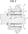
FIG. 3 is a sectional view illustrating the detail of the fixing means illustrated inFIG. 1 . - There is illustrated in
FIG. 1 a turret tool rest (tool rest for a machine tool) 1, which is used, for example, in a machine tool, such as an NC lathe. - The turret tool rest 1 includes a
turret 4 turnably (i.e., rotatably) supported by asupport stand 2 by means of a turret-turningshaft 3. Theturret 4, which is comprised, for example, of a steel material, is polygonal in shape having a plurality ofturret faces 4a and fixed on one side coaxially to the turret-turningshaft 3. Theturret 4 has a hollow interior, with a tip end opening on the other side, which is closed by acover 5. - The turret-turning
shaft 3 is connected to an indexing motor, not shown, through agear 3a that is fixed on the proximal end side, such that the turningshaft 3 can be driven in rotation by means of the indexing motor. - Around the
turret 4, there are provided a plurality of tool-mountingportions 6 on which the rotary tools may be mounted. In the illustrated embodiment, around theturret 4, twelve (12) turret faces 14 are each provided with two tool-mountingportions 6, i.e., twenty four (24)tool mounting portions 6 in total, which are arranged side by side in the axial direction (the direction along the turning axis) of the turret-turningshaft 3, in two stages arranged side by side in the axial direction of the turret-turningshaft 3. The twelve tool-mountingportions 6 arranged equidistantly in the circumferential direction on one side (right side in the figure) in the axial direction of the turret-turningshaft 3 are the tool mounting portions on the upper stage, while the twelve tool-mountingportions 6 arranged equidistantly in the circumferential direction on the other side (left side in the figure) in the axial direction of theturret turning shaft 3 are the tool mounting portions on the lower stage. - Each tool-
mounting portion 6 is configured to have a through-hole extending radially through theturret 4. The tool-mounting portion 6 is adopted to mount thereon arotary tool 8, such as a drill or an end mill, by means of aholder 7. Therotary tool 8 mounted on the tool-mounting portion 6 is rotatably supported by theholder 7, through a bearing, and can be rotated with the radial direction of theturret 4 as its rotary axis. - As the
rotary tool 8 to be mounted on the tool-mounting portion 6, thee is used a tool including a toolmain body 8a provided with cutting blades, as well as ashank 8b that is coaxial with the toolmain body 8a, having a lower end surface integrally provided with an engaged portion in the form of atenon 8c (see,FIG. 2 ) that extends in the radial direction. - While
FIG. 1 shows a state in which onerotary tool 8 is mounted on an upper stage tool-mounting portion 6, the other tool-mountingportions 6, whether in the upper stage or the lower stage, may be mounted with rotary tools as necessary, such that theturret 4 is equipped with a plurality ofrotary tools 8. The tool-mounting portion 6 may also be mounted with a non-rotating tool, such as a bite. - A
coupling mechanism 9 is provided between theturret 4 and the support stand 2. Theturret 4 can be locked by thecoupling mechanism 9 and thereby positioned in a prescribed index position corresponding to each tool-mounting portion 6. Theturret turning shaft 3 can be driven in the axial direction by means of a drive mechanism, not shown, to move theturret 4 in a direction away from the support stand 2 so as to disengage the coupling by the coupling mechanism. The turret-turningshaft 3 is then driven by an indexing motor, not shown, in rotation by a prescribed angle, before thecoupling mechanism 9 is reengaged such that any tool-mounting portion 6 can be positioned selectively in a prescribed index position. For example, tworotary tools 8, which are mounted on two tool-mountingportions 6 in a juxtaposed relation along the turning axis, may be simultaneously indexed at the respective positions that can be driven in rotation, by means of a prescribed indexing turning. The machine tool is adapted to perform machining of a workpiece clamped by the main spindle, by means of a tool, such as arotary tool 8 mounted on a tool-mounting portion 6 that has been positioned in the indexed position. - The
coupling mechanism 9 is not limited to an arrangement wherein the engagement and disengagement is achieved by the drive mechanism for moving theturret 4 in the axial direction away from thesupport stand 2; there may also be used a mechanism (e.g., a three-piece coupling) wherein the engagement and disengagement can be achieved within theturret 4 without moving theturret 4 in the axial direction relative to thesupport stand 2 - A tool-rotating
drive shaft 10 is arranged on the axis of the turret-turningshaft 3. The tool-rotatingdrive shaft 10 is adapted to be driven in rotation by means of a tool-rotating motor, not shown. As the tool-rotating motor, there is used a motor with of a constitution that allows for a phase control of the stopping position (i.e., the angular position upon stopping) of the tool-rotatingshaft 10, such as a servomotor, whereby the tool-rotatingshaft 10 is stopped at a stopping position always with a prescribed stopping phase. - A cylindrical
stationary shaft 11 is arranged between the turret-turningshaft 3 and the tool-rotatingdrive shaft 10 and is non-rotatably supported by thesupport stand 2, while a casing-likestationary body 12 is fixed to the tip end of thestationary shaft 11. Thestationary body 12 is supported by the support stand 2 through thestationary shaft 11 and is non-rotatably arranged inside theturret 4 regardless of the turning of theturret 4. Thecover 5 fixed to theturret 4 is rotatably supported on thefixed body 12 by a bearing. - The
turret 4 is provided with a lower stagepower transmission mechanism 20 for transmitting the rotation of the tool-rotatingdrive shaft 10 to therotary tool 8 mounted on the lower stagetool mounting portion 6, as well as an upper stagepower transmission mechanism 30 for transmitting the rotation of the tool-rotating drive shaft to therotary tool 8 mounted on the upper stage tool-mounting portion 6. - The lower stage
power transmission mechanism 20 has abevel gear 21 as an input portion fixed to the tool-rotatingdrive shaft 10. Thebevel gear 21 has a key 22c disposed in a shaft-side key groove 22a formed on the outer peripheral surface of the tool-rotatingdrive shaft 10 and a gear-side key groove 22b provided in thebevel gear 21, so that the bevel gear is fixed relative to the tool-rotatingdrive shaft 10 and is rotated together with the tool-rotatingdrive shaft 10. Thebevel gear 21 is not limited to the configuration described above. Various configurations may be adopted as long as thebevel gear 21 can be fixed in a state where it is prevented from rotation relative to the tool rotatingdrive shaft 10, such as, a configuration where thebevel gear 21 is prevented from rotation relative to the tool rotatingdrive shaft 10 by a spline engagement of the inner peripheral surface of thebevel gear 21 with a spline provided on the outer peripheral surface of the tool-rotatingdrive shaft 10. - The
power transmission mechanism 20 includes a lower-stage tool-rotatingtransmission shaft 23 that is rotatably supported on thefixed body 12 by a bearing. The tool-rotatingtransmission shaft 23 has a base end that protrudes into thefixed body 12, and abevel gear 24 is fixed to the base end. Thebevel gear 24 is meshed with thebevel gear 21 fixed to the tool-rotatingdrive shaft 10, and the tool-rotatingtransmission shaft 23 is adapted to be driven in rotation by thebevel gear 21 that rotates together with the tool-rotatingdrive shaft 10. - The tool-rotating
transmission shaft 23 is arranged coaxially with therotary tool 8 mounted on the lower-tool mounting portion 6 at the index position. At the tip end of the tool-rotatingtransmission shaft 23 facing thetool mounting portion 6, there is provided amortise 23a as an engaging portion extending along the radial direction. Themortise 23a is directed in a direction along the turning direction of theturret 4 when the tool-rotatingtransmission shaft 23 is stopped at a position where the predetermined rotation phase is achieved by a tool-rotating motor capable of phase control of the stop position. By rotating theturret 4 with theridge groove 23a directed in the direction along the turning direction of theturret 4, thetenon 8c of therotary tool 8 mounted on the lower stage tool-mounting portion 6, which has moved toward the index position, can be slidably engaged with themortise 23a. By causing thetenon 8c of therotary tool 8, which has moved to the index position, to engage with themortise 23a, the rotation of the tool-rotatingtransmission shaft 23 can be transmitted to therotary tool 8. When the lowerstage rotary tool 8 is at a position other than the index position, thetenon 8c does not engage with themortise 23a, and the rotation of the tool-rotatingtransmission shaft 23 is not transmitted to therotary tool 8. A clutch mechanism for interrupting power transmission between therotary tool 8 and the tool-rotatingtransmission shaft 23 is constituted by thetenon 8c and themortise 23a. - The upper stage
power transmission mechanism 30 has abevel gear 31 as an input portion fixed to the tool-rotatingdrive shaft 10. Thebevel gear 31 is fixed to the tool-rotatingdrive shaft 10 with a fixing means 40 that is comprised of an adjustment means and rotates together with the tool-rotatingdrive shaft 10. The details of the structure for fixing thebevel gear 31 to the tool-rotatingdrive shaft 10 with the fixing means 40 will be described later. - The
power transmission mechanism 30 includes an upper stage tool rotatingtransmission shaft 33 that is disposed in parallel with the lower stage tool rotatingtransmission shaft 23 that, in turn, is rotatably supported by the fixedbody 12 by bearings. The base end of the tool-rotatingtransmission shaft 33 protrudes into thestationary body 12, and abevel gear 34 is fixed to the base end. Thebevel gear 34 is meshed with thebevel gear 31 fixed to the tool-rotatingdrive shaft 10, and the tool-rotatingtransmission shaft 33 is adapted to be driven in rotation by thebevel gear 31 that rotates together with the tool-rotatingdrive shaft 10. - The tool-rotating
transmission shaft 33 is arranged coaxially with therotary tool 8 mounted on the upper stage tool-mountingportion 6 at the index position. At the tip end of the tool-rotatingtransmission shaft 33 facing thetool mounting portion 6, there is provided amortise 33a as an engaging portion extending along the radial direction. Themortise 33a is directed in a direction along the turning direction of theturret 4 when the tool-rotatingtransmission shaft 33 is stopped at a position where a predetermined rotation phase is achieved by a tool-rotating motor capable of phase control of the stop position. By rotating theturret 4 with themortise 33a directed in the direction along the turning direction of theturret 4, thetenon 8c of the upperstage rotary tool 8 moved toward the index position ca be slidingly engaged into themortise 33a. The rotation of the tool-rotatingtransmission shaft 33 can be transmitted to therotary tool 8 by the engagement of thetenon 8c of therotary tool 8 moved to the indexing position with themortise 33a. When the upperstage rotary tool 8 is at a position other than the index position, thetenon 8c does not engage with themortise 33a and therotary tool 8 is in a state where the rotation of the tool-rotatingtransmission shaft 33 is not transmitted. A clutch mechanism for interrupting power transmission between therotary tool 8 and the tool-rotatingtransmission shaft 33 is comprised of thetenon 8c and themortise 33a. - Although not shown in detail, in a portion of the outer peripheral surface of the fixed
body 12 corresponding to the lower stage tool-mountingportion 6 and the upper stage tool-mountingportion 6, there may be provided with a circumferential groove that is contiguous with themortises turret 4. When a circumferential groove is provided on the outer peripheral surface of thestationary body 12, thetenon 8c in a position other than the index position may be engaged with the circumferential groove, such that thetenon 8c ca be positively maintained also in a posture along the turning direction of theturret 4 and moved to the index position with that posture to positively engage thetenon 8 c into themortises transmission shafts - The fixing means 40 for fixing the upper
stage bevel gear 31 to the tool-rotatingdrive shaft 10 is adapted to fix thebevel gear 31 to the tool-rotatingdrive shaft 10 at an arbitrary circumferential position. As the fixing means 40, for example, there may be used the one with a constitution as illustrated inFIG. 3 . - The fixing means 40 illustrated in
FIG. 3 includes aninner ring 41 that is formed of a substantially cylindrical steel material having a C-shaped cross section when viewed in the axial direction of the tool-rotatingdrive shaft 10, and anouter ring 42 which is formed of a substantially cylindrical steel material that can be deformed to expand its diameter. Theinner ring 41 is provided with a plurality of through-holes 41a arranged at equal intervals in the circumferential direction, andbolts 43 inserted through these through-holes 41a are screw-connected to threadedholes 42a provided in theouter ring 42. Theinner ring 41 has a taperedcylindrical portion 41b with a tapered outer peripheral surface, and atapered surface 42b provided on the inner peripheral surface of theouter ring 42 is in contact with the outer peripheral surface of the taperedcylindrical portion 41b. The portions other than the taperedsurface 42b of theouter ring 42 are spaced apart from theinner ring 41 in the axial direction. Thus, when thebolt 43 is tightened, the outer peripheral surface of the taperedcylindrical portion 41b and thetapered surface 42b are more deeply engaged, thereby deforming theinner ring 41 to contract and also deforming theouter ring 42 to expand. - The fixing means 40 with the constitution as described above is arranged inside the
bevel gear 31 and attached to the tool-rotatingdrive shaft 10. The part of the tool-rotatingdrive shaft 10 to which thebevel gear 31 is fixed may be a part having a circular outer periphery without a keyway or the like. Before thebolt 43 is tightened, the inner peripheral surface of theinner ring 41 has a slight gap with respect to the outer peripheral surface of the tool-rotatingdrive shaft 10, such that thebevel gear 31 may be rotated relative to the tool-rotatingdrive shaft 10, thereby allowing an adjustment to an arbitrary circumferential position. By tightening eachbolt 43, theinner ring 41 may be deformed in a reduced diameter between the tool-rotatingdrive shaft 10 and thebevel gear 31, with thebevel gear 31 at a desired circumferential position with respect to the tool-rotatingdrive shaft 10, while deforming and expanding theouter ring 42 such that thebevel gear 31 is fixed at this position in a state where it is prevented from rotation with respect to the tool-rotatingdrive shaft 10. By loosening eachbolt 43 again, thebevel gear 31 can be rotated relative to the tool-rotatingdrive shaft 10 to return to an adjustable state in any circumferential position. Thus, thebevel gear 31 is fixed to the tool-rotatingdrive shaft 10 by the fixing means 40 after shifting the fixing position of thebevel gear 31 with respect to the tool-rotatingdrive shaft 10 in the rotation direction with respect to the tool-rotatingdrive shaft 10. thereby allowing the phase of the engagingportion 23a to be adjusted with respect to the tool-rotatingdrive shaft 10. - The axial position of the
bevel gear 31 is defined by aspacer 44 that is engaged with the tool-rotatingdrive shaft 10. - When a plurality of tool-mounting
portions 6 are provided around theturret 4 separately in a lower stage and an upper stage arranged side by side in the axial direction of the turret-turningshaft 3, and a lower stagepower transmission mechanism 20 with the above-described clutch mechanism and the upper stagepower transmission mechanism 30 are provided corresponding to thetool mounting section 6 of each stage, in order that themortises corresponding tenon 8c, it would be necessary to ensure that the rotation phase of the tool-rotatingtransmission shaft 23 of the lower stagepower transmission mechanism 20 and the rotation phase of the tool-rotatingtransmission shaft 33 of the upper-stagepower transmission mechanism 30 are matched with each other so that, when theturret 4 is turned, themortises turret 4. When there is adopted a structure in which thebevel gear 21 of the lower stagepower transmission mechanism 20 and thebevel gear 31 of the upper stagepower transmission mechanism 30 are both fixed to the tool-rotatingdrive shaft 10 by means of the shaft sidekey groove 22a, the gear sidekey groove 22b and the key 22c, there may be a case due to problems such as machining accuracy, where the phases of therespective ridge grooves mortises - In the present embodiment, the lower stage
power transmission mechanism 20 including thebevel gear 21 fixed to the tool-rotatingdrive shaft 10 by means of the shaft sidekey groove 22a, the gear sidekey groove 22b and the key 22c is used as a reference, and thebevel gear 31 of the upper stagepower transmission mechanism 30 is fixed to the tool-rotatingdrive shaft 10 by means of the fixing means 40 comprised of the adjusting means that can be fixed to the tool-rotatingdrive shaft 10 at an arbitrary circumferential position. Therefore, the rotation position of the tool-rotatingtransmission shaft 33 of the upper stagepower transmission mechanism 30 or themortise 33a has been adjusted so that the rotational phase is matched with that of the tool-rotatingtransmission shaft 23 of the lower stagepower transmission mechanism 20 as a reference, and the rotation position of the fixing means 40 is subsequently adjusted so that thebevel gear 31 is fixed to the tool-rotatingdrive shaft 10 by tightening thebolts 43 of the fixing means 40, thereby making it possible readily and positively match the phase of themortices mortises bolt 43 of the fixing means 40 is loosened, and the rotation position of the upperstage bevel gear 31 is adjusted relative to the tool-rotatingdrive shaft 10 such that the phases of themortices bevel gear 31 is fixed to the tool-rotatingdrive shaft 10 again by the fixing means 40, thereby allowing the phases of themortises - The present disclosure is not limited to the embodiment described above and various modifications may be made without departing from the scope of the invention.
- In the embodiment described above, the engaging portions provided in the tool-rotating
transmission shafts mortises rotary tool 8 is formed as atenon 8c extending along the radial direction. However, the engaging portions provided in the tool-rotatingtransmission shafts rotary tool 8 may be formed as a mortise extending along the radial direction. - In the embodiment described above, only the
bevel gear 31 of the upper stagepower transmission mechanism 30 is fixed to the tool-rotatingdrive shaft 10 by the fixing means 40. However, only thebevel gear 21 of the lower stagepower transmission mechanism 20 may be fixed to the tool-rotatingdrive shaft 10 by the fixing means 40 comprised of the adjustment means, or thebevel gear 21 of the lower stagepower transmission mechanism 20 and thebevel gear 31 of the upper stagepower transmission mechanism 30 may both be fixed to the tool-rotatingdrive shaft 10 by the fixing means 40 comprised of the adjusting means. - In the embodiment described above, the
turret 4 is provided with a plurality oftool mounting portions 6 divided into two stages, the upper stage and the lower stage. However, a plurality oftool mounting parts 6 may be provided in three or more stages. In this case, all the stage bevel gears other than the reference stage bevel gear may be fixed to the tool-rotatingdrive shaft 10 by the fixing means 40 comprised of the adjusting means. - In the embodiment described above, the input portions of the respective stages are comprised of the bevel gears 21 and 31, but this is not mandatory. Various configurations can be adopted as long as the tool-rotating
drive shaft 10 is fixed to the tool-rotatingdrive shaft 10 for transmitting the rotation of the tool-rotating drive shaft to the tool-rotatingtransmission shafts - The fixing means 40 comprised of the adjusting means is not limited to the one having the configuration described above, and other configurations may be adopted as long as and the
bevel gear 31 can be fixed at an arbitrary circumferential position with respect to the tool-rotatingdrive shaft 10 and the phase of the upper tool-rotatingtransmission shaft 33 or themortise 33a in the rotation direction can be adjusted relative to the phase of the lower stage tool-rotatingtransmission shaft 23 or themortise 23a in the rotation direction as the reference. - The adjusting means is not limited to the one constituting the fixing means 40, and a constitution different from the fixing means 40 may be adopted as long as the
tenon 8c can be adjusted in phase relative to the tool-rotatingdrive shaft 10 to thereby engage themortises tenon 8c. -
- 1
- Turret tool rest (tool rest for machine tool)
- 2
- Support stand
- 3
- Turret-turning shaft
- 3a
- Gear wheel
- 4
- Turret
- 4a
- Turret face
- 5
- Cover
- 6
- Tool-mounting portion
- 7
- Holder
- 8
- Rotary tool
- 8a
- Tool main body
- 8b
- Shank
- 8c
- Tenon (engaged portion)
- 9
- Coupling mechanism
- 10
- Tool-rotating drive shaft
- 11
- Stationary shaft
- 12
- Stationary body
- 20
- Lower stage power transmission mechanism
- 21
- Bevel gear (input portion)
- 22a
- Shaft side key groove
- 22b
- Gear wheel side key groove
- 22c
- Key
- 23
- Tool-rotating transmission shaft
- 23a
- Mortise (engaging portion)
- 24
- Bevel gear
- 30
- Upper stage power transmission mechanism
- 31
- Bevel gear (input portion)
- 33
- Tool-rotating transmission shaft
- 33a
- Mortise (engaging portion)
- 34
- Bevel gear
- 40
- Fixing means (adjusting means)
- 41
- Inner ring
- 41a
- Through-hole
- 41b
- Tapered cylinder portion
- 42
- Outer ring
- 42a
- Threaded hole
- 42b
- Tapered face
- 43
- Bolt
- 44
- Spacer
Claims (5)
- A tool rest for a machine tool, with a plurality of rotary tools, and a rotatably supported tool-rotating drive shaft whose rotation is transmitted to each rotary tool, the tool rest comprising:a plurality of input portions fixed to the tool-rotating drive shaft; andengaging portions corresponding to the respective input portions, rotatably supported and adapted to be driven in rotation by the input portion for engaging with the respective engaged portions of the rotary tool when a prescribed angular phase is reached;wherein an adjusting means is provided between a prescribed input portion and the engaging portion, for adjusting the phase of the engaging portion relative to the tool-rotating drive shaft such that the engaging portions and the corresponding engaged portions are engaged simultaneously.
- A tool rest according to claim 1, further provided with a fixing means for fixing the input portions to the tool-rotating drive shaft, the fixing means being comprised of the adjusting means.
- A tool rest according to any one of claims 1 and 2, wherein the input portion is comprised of a gear wheel, and wherein the phase of the engaging portion is adjusted relative to the tool-rotating drive shaft, by shifting the fixing position of the gear wheel to the tool-rotating drive shaft, in a rotating direction relative to the tool-rotating drive shaft.
- A tool rest according to any one of claims 1 to 3, further provided with a rotatable tool-mounting portion for mounting the rotary tool thereon, wherein two rotary tools are mounted along a turning axis, and wherein the two rotary tools are adapted to be simultaneously indexed and driven for rotation by a prescribed indexing turning of the tool-mounting portion.
- A tool rest according to claim 4, wherein the engaging portion and the engaged portion are comprised of a tenon and a mortise, respectively, wherein the tenon and the mortise are engageable by a turning of the tool-mounting portion.
Applications Claiming Priority (2)
| Application Number | Priority Date | Filing Date | Title |
|---|---|---|---|
| JP2017127788A JP7066341B2 (en) | 2017-06-29 | 2017-06-29 | Machine tool tool post |
| PCT/JP2018/021276 WO2019003803A1 (en) | 2017-06-29 | 2018-06-01 | MACHINE TOOL TOOL HOLDER |
Publications (3)
| Publication Number | Publication Date |
|---|---|
| EP3646973A1 true EP3646973A1 (en) | 2020-05-06 |
| EP3646973A4 EP3646973A4 (en) | 2021-05-05 |
| EP3646973B1 EP3646973B1 (en) | 2022-02-09 |
Family
ID=64740576
Family Applications (1)
| Application Number | Title | Priority Date | Filing Date |
|---|---|---|---|
| EP18823113.8A Active EP3646973B1 (en) | 2017-06-29 | 2018-06-01 | Tool rest for machine tool |
Country Status (8)
| Country | Link |
|---|---|
| US (1) | US11020806B2 (en) |
| EP (1) | EP3646973B1 (en) |
| JP (1) | JP7066341B2 (en) |
| KR (1) | KR102448895B1 (en) |
| CN (1) | CN110636917B (en) |
| ES (1) | ES2907823T3 (en) |
| TW (1) | TWI732124B (en) |
| WO (1) | WO2019003803A1 (en) |
Families Citing this family (1)
| Publication number | Priority date | Publication date | Assignee | Title |
|---|---|---|---|---|
| JP2026078618A (en) * | 2024-10-29 | 2026-05-15 | シチズンマシナリー株式会社 | Rotary tools and turret tool posts equipped with rotary tools |
Family Cites Families (25)
| Publication number | Priority date | Publication date | Assignee | Title |
|---|---|---|---|---|
| US4087890A (en) * | 1974-09-10 | 1978-05-09 | Citizen Watch Company Limited | Compound lathe |
| US4656708A (en) * | 1985-10-29 | 1987-04-14 | Hardinge Brothers, Inc. | Live tooling turret |
| JPH0722843B2 (en) | 1988-10-04 | 1995-03-15 | シチズン時計株式会社 | Turret for combined machining lathe |
| JPH0773804B2 (en) * | 1989-05-22 | 1995-08-09 | 大昭和精機株式会社 | Selective drive device for rotary tools in turret lathe |
| JP2889426B2 (en) | 1992-02-20 | 1999-05-10 | 中村留精密工業株式会社 | Turret tool axis drive |
| DE4235095C2 (en) * | 1992-10-17 | 1997-04-30 | Gildemeister Ag | Tool turret |
| JPH07227704A (en) | 1994-02-16 | 1995-08-29 | Star Micronics Co Ltd | Turret type turret for automatic lathe |
| JPH10291104A (en) | 1997-04-15 | 1998-11-04 | Nakamura Tome Precision Ind Co Ltd | Rotary tool turret |
| JP2003071615A (en) * | 2001-08-30 | 2003-03-12 | Mori Seiki Co Ltd | Turret turret |
| JP2003311501A (en) * | 2002-04-17 | 2003-11-05 | Nakamura Tome Precision Ind Co Ltd | Simultaneous machining method of opposed work of two-spindle opposed lathe |
| JP4316850B2 (en) * | 2002-09-26 | 2009-08-19 | 森精機興産株式会社 | Machining method in complex machine tool |
| JP4379877B2 (en) * | 2004-09-29 | 2009-12-09 | 株式会社森精機製作所 | Machine tool turret |
| JP2006150574A (en) | 2004-12-01 | 2006-06-15 | Tong-Tai Machine & Tool Co Ltd | Turning machine tool |
| JP2007154930A (en) | 2005-12-01 | 2007-06-21 | Seisa Gear Ltd | Biaxial output gearing |
| KR100653511B1 (en) * | 2006-01-16 | 2006-12-05 | 두산메카텍 주식회사 | Lathe turret tool stand with adjustable forward and backward position on the rotating tool drive shaft |
| JP4599623B2 (en) * | 2006-01-30 | 2010-12-15 | 株式会社セイキテクノデザイン | Turret type tool post |
| EP1992435B1 (en) * | 2007-05-16 | 2009-11-18 | Alps Tool Co., Ltd. | Tool holder positioning device |
| JP5093805B2 (en) * | 2008-02-01 | 2012-12-12 | 津田駒工業株式会社 | Strengthening device for index table clamping device |
| JP2010023207A (en) * | 2008-07-23 | 2010-02-04 | Miyano:Kk | Turret dividing device |
| CN201483011U (en) * | 2009-08-04 | 2010-05-26 | 山东鲁南机床有限公司 | Power cutter tower |
| JP5831349B2 (en) * | 2012-04-24 | 2015-12-09 | スター精密株式会社 | Machine tools that can be fitted with rotating tool units |
| DE202013101913U1 (en) * | 2013-05-02 | 2013-05-16 | Apex Dynamics Inc. | Single-engine turret device |
| ES2775437T3 (en) * | 2014-03-31 | 2020-07-27 | Citizen Watch Co Ltd | Turret tool post and machine tool equipped with turret tool post |
| JP6425601B2 (en) * | 2015-03-31 | 2018-11-21 | シチズン時計株式会社 | Tool post of machine tool |
| JP6659232B2 (en) * | 2015-04-14 | 2020-03-04 | ナブテスコ株式会社 | Gear transmission |
-
2017
- 2017-06-29 JP JP2017127788A patent/JP7066341B2/en active Active
-
2018
- 2018-06-01 KR KR1020197034020A patent/KR102448895B1/en active Active
- 2018-06-01 EP EP18823113.8A patent/EP3646973B1/en active Active
- 2018-06-01 ES ES18823113T patent/ES2907823T3/en active Active
- 2018-06-01 US US16/613,121 patent/US11020806B2/en active Active
- 2018-06-01 WO PCT/JP2018/021276 patent/WO2019003803A1/en not_active Ceased
- 2018-06-01 CN CN201880032338.1A patent/CN110636917B/en active Active
- 2018-06-07 TW TW107119712A patent/TWI732124B/en active
Also Published As
| Publication number | Publication date |
|---|---|
| EP3646973B1 (en) | 2022-02-09 |
| US20200108450A1 (en) | 2020-04-09 |
| CN110636917A (en) | 2019-12-31 |
| JP7066341B2 (en) | 2022-05-13 |
| TW201904706A (en) | 2019-02-01 |
| KR102448895B1 (en) | 2022-09-30 |
| ES2907823T3 (en) | 2022-04-26 |
| EP3646973A4 (en) | 2021-05-05 |
| TWI732124B (en) | 2021-07-01 |
| CN110636917B (en) | 2021-12-28 |
| WO2019003803A1 (en) | 2019-01-03 |
| US11020806B2 (en) | 2021-06-01 |
| KR20200021923A (en) | 2020-03-02 |
| JP2019010696A (en) | 2019-01-24 |
Similar Documents
| Publication | Publication Date | Title |
|---|---|---|
| EP2961564B1 (en) | Positive feed tool with a slip clutch and a method to prevent jamming | |
| EP1967321B1 (en) | Index table | |
| US20100003096A1 (en) | Ring-rolling bearing with axial displacement and shaping tooling equipped with such a bearing | |
| CN102672218A (en) | Tool rest | |
| US20140260840A1 (en) | Machining apparatus | |
| US9089940B2 (en) | Drive device | |
| EP3646973B1 (en) | Tool rest for machine tool | |
| JP5410234B2 (en) | Multi-axis head | |
| EP3319746B1 (en) | Pipe end machining device | |
| EP3156160B1 (en) | Machine tool | |
| KR100655923B1 (en) | Turret tool bench with gearbox | |
| CN102528470A (en) | A double-sided right-angle milling head | |
| US5271134A (en) | Tool turret with axial reactive force | |
| JP6472697B2 (en) | Rotary table with switchable reduction ratio | |
| US3237487A (en) | Drilling machine, especially for drilling turbine housings | |
| EP3677366B1 (en) | Turret tool post | |
| RU2340428C2 (en) | Cutting head for processing of multithread grooves in billet openings | |
| US10940543B2 (en) | Drilling tool and method of operating a drilling tool | |
| JP2019508278A (en) | Tool spindle | |
| KR101670122B1 (en) | Attachment, door-shape machining center including attachment, and processing method using door-shape machining center | |
| US12539570B2 (en) | Cam mechanism, cam mechanism manufacturing method, camshaft manufacturing method, NC rotary table | |
| KR20240168739A (en) | Tool post device for lathe | |
| KR101679431B1 (en) | Back-Lash reducing double pinion gear structure using eccentricity key | |
| KR20090093316A (en) | Portable turning machine for processing rotor axis of atomic reactor turbine | |
| KR20170077999A (en) | Sprocket assembly for switchable motor fix |
Legal Events
| Date | Code | Title | Description |
|---|---|---|---|
| STAA | Information on the status of an ep patent application or granted ep patent |
Free format text: STATUS: THE INTERNATIONAL PUBLICATION HAS BEEN MADE |
|
| PUAI | Public reference made under article 153(3) epc to a published international application that has entered the european phase |
Free format text: ORIGINAL CODE: 0009012 |
|
| STAA | Information on the status of an ep patent application or granted ep patent |
Free format text: STATUS: REQUEST FOR EXAMINATION WAS MADE |
|
| 17P | Request for examination filed |
Effective date: 20191112 |
|
| AK | Designated contracting states |
Kind code of ref document: A1 Designated state(s): AL AT BE BG CH CY CZ DE DK EE ES FI FR GB GR HR HU IE IS IT LI LT LU LV MC MK MT NL NO PL PT RO RS SE SI SK SM TR |
|
| AX | Request for extension of the european patent |
Extension state: BA ME |
|
| DAV | Request for validation of the european patent (deleted) | ||
| DAX | Request for extension of the european patent (deleted) | ||
| A4 | Supplementary search report drawn up and despatched |
Effective date: 20210401 |
|
| RIC1 | Information provided on ipc code assigned before grant |
Ipc: B23B 29/24 20060101AFI20210326BHEP Ipc: B23Q 5/04 20060101ALI20210326BHEP Ipc: B23B 29/32 20060101ALI20210326BHEP Ipc: B23Q 39/00 20060101ALI20210326BHEP |
|
| GRAP | Despatch of communication of intention to grant a patent |
Free format text: ORIGINAL CODE: EPIDOSNIGR1 |
|
| STAA | Information on the status of an ep patent application or granted ep patent |
Free format text: STATUS: GRANT OF PATENT IS INTENDED |
|
| INTG | Intention to grant announced |
Effective date: 20211124 |
|
| GRAS | Grant fee paid |
Free format text: ORIGINAL CODE: EPIDOSNIGR3 |
|
| GRAA | (expected) grant |
Free format text: ORIGINAL CODE: 0009210 |
|
| STAA | Information on the status of an ep patent application or granted ep patent |
Free format text: STATUS: THE PATENT HAS BEEN GRANTED |
|
| AK | Designated contracting states |
Kind code of ref document: B1 Designated state(s): AL AT BE BG CH CY CZ DE DK EE ES FI FR GB GR HR HU IE IS IT LI LT LU LV MC MK MT NL NO PL PT RO RS SE SI SK SM TR |
|
| REG | Reference to a national code |
Ref country code: GB Ref legal event code: FG4D |
|
| REG | Reference to a national code |
Ref country code: CH Ref legal event code: EP Ref country code: AT Ref legal event code: REF Ref document number: 1467196 Country of ref document: AT Kind code of ref document: T Effective date: 20220215 |
|
| REG | Reference to a national code |
Ref country code: IE Ref legal event code: FG4D |
|
| REG | Reference to a national code |
Ref country code: DE Ref legal event code: R096 Ref document number: 602018030687 Country of ref document: DE |
|
| REG | Reference to a national code |
Ref country code: ES Ref legal event code: FG2A Ref document number: 2907823 Country of ref document: ES Kind code of ref document: T3 Effective date: 20220426 |
|
| REG | Reference to a national code |
Ref country code: LT Ref legal event code: MG9D |
|
| REG | Reference to a national code |
Ref country code: NL Ref legal event code: MP Effective date: 20220209 |
|
| REG | Reference to a national code |
Ref country code: AT Ref legal event code: MK05 Ref document number: 1467196 Country of ref document: AT Kind code of ref document: T Effective date: 20220209 |
|
| PG25 | Lapsed in a contracting state [announced via postgrant information from national office to epo] |
Ref country code: SE Free format text: LAPSE BECAUSE OF FAILURE TO SUBMIT A TRANSLATION OF THE DESCRIPTION OR TO PAY THE FEE WITHIN THE PRESCRIBED TIME-LIMIT Effective date: 20220209 Ref country code: RS Free format text: LAPSE BECAUSE OF FAILURE TO SUBMIT A TRANSLATION OF THE DESCRIPTION OR TO PAY THE FEE WITHIN THE PRESCRIBED TIME-LIMIT Effective date: 20220209 Ref country code: PT Free format text: LAPSE BECAUSE OF FAILURE TO SUBMIT A TRANSLATION OF THE DESCRIPTION OR TO PAY THE FEE WITHIN THE PRESCRIBED TIME-LIMIT Effective date: 20220609 Ref country code: NO Free format text: LAPSE BECAUSE OF FAILURE TO SUBMIT A TRANSLATION OF THE DESCRIPTION OR TO PAY THE FEE WITHIN THE PRESCRIBED TIME-LIMIT Effective date: 20220509 Ref country code: NL Free format text: LAPSE BECAUSE OF FAILURE TO SUBMIT A TRANSLATION OF THE DESCRIPTION OR TO PAY THE FEE WITHIN THE PRESCRIBED TIME-LIMIT Effective date: 20220209 Ref country code: LT Free format text: LAPSE BECAUSE OF FAILURE TO SUBMIT A TRANSLATION OF THE DESCRIPTION OR TO PAY THE FEE WITHIN THE PRESCRIBED TIME-LIMIT Effective date: 20220209 Ref country code: HR Free format text: LAPSE BECAUSE OF FAILURE TO SUBMIT A TRANSLATION OF THE DESCRIPTION OR TO PAY THE FEE WITHIN THE PRESCRIBED TIME-LIMIT Effective date: 20220209 Ref country code: BG Free format text: LAPSE BECAUSE OF FAILURE TO SUBMIT A TRANSLATION OF THE DESCRIPTION OR TO PAY THE FEE WITHIN THE PRESCRIBED TIME-LIMIT Effective date: 20220509 |
|
| PG25 | Lapsed in a contracting state [announced via postgrant information from national office to epo] |
Ref country code: PL Free format text: LAPSE BECAUSE OF FAILURE TO SUBMIT A TRANSLATION OF THE DESCRIPTION OR TO PAY THE FEE WITHIN THE PRESCRIBED TIME-LIMIT Effective date: 20220209 Ref country code: LV Free format text: LAPSE BECAUSE OF FAILURE TO SUBMIT A TRANSLATION OF THE DESCRIPTION OR TO PAY THE FEE WITHIN THE PRESCRIBED TIME-LIMIT Effective date: 20220209 Ref country code: GR Free format text: LAPSE BECAUSE OF FAILURE TO SUBMIT A TRANSLATION OF THE DESCRIPTION OR TO PAY THE FEE WITHIN THE PRESCRIBED TIME-LIMIT Effective date: 20220510 Ref country code: FI Free format text: LAPSE BECAUSE OF FAILURE TO SUBMIT A TRANSLATION OF THE DESCRIPTION OR TO PAY THE FEE WITHIN THE PRESCRIBED TIME-LIMIT Effective date: 20220209 Ref country code: AT Free format text: LAPSE BECAUSE OF FAILURE TO SUBMIT A TRANSLATION OF THE DESCRIPTION OR TO PAY THE FEE WITHIN THE PRESCRIBED TIME-LIMIT Effective date: 20220209 |
|
| PG25 | Lapsed in a contracting state [announced via postgrant information from national office to epo] |
Ref country code: IS Free format text: LAPSE BECAUSE OF FAILURE TO SUBMIT A TRANSLATION OF THE DESCRIPTION OR TO PAY THE FEE WITHIN THE PRESCRIBED TIME-LIMIT Effective date: 20220609 |
|
| PG25 | Lapsed in a contracting state [announced via postgrant information from national office to epo] |
Ref country code: SM Free format text: LAPSE BECAUSE OF FAILURE TO SUBMIT A TRANSLATION OF THE DESCRIPTION OR TO PAY THE FEE WITHIN THE PRESCRIBED TIME-LIMIT Effective date: 20220209 Ref country code: SK Free format text: LAPSE BECAUSE OF FAILURE TO SUBMIT A TRANSLATION OF THE DESCRIPTION OR TO PAY THE FEE WITHIN THE PRESCRIBED TIME-LIMIT Effective date: 20220209 Ref country code: RO Free format text: LAPSE BECAUSE OF FAILURE TO SUBMIT A TRANSLATION OF THE DESCRIPTION OR TO PAY THE FEE WITHIN THE PRESCRIBED TIME-LIMIT Effective date: 20220209 Ref country code: EE Free format text: LAPSE BECAUSE OF FAILURE TO SUBMIT A TRANSLATION OF THE DESCRIPTION OR TO PAY THE FEE WITHIN THE PRESCRIBED TIME-LIMIT Effective date: 20220209 Ref country code: DK Free format text: LAPSE BECAUSE OF FAILURE TO SUBMIT A TRANSLATION OF THE DESCRIPTION OR TO PAY THE FEE WITHIN THE PRESCRIBED TIME-LIMIT Effective date: 20220209 Ref country code: CZ Free format text: LAPSE BECAUSE OF FAILURE TO SUBMIT A TRANSLATION OF THE DESCRIPTION OR TO PAY THE FEE WITHIN THE PRESCRIBED TIME-LIMIT Effective date: 20220209 |
|
| REG | Reference to a national code |
Ref country code: DE Ref legal event code: R097 Ref document number: 602018030687 Country of ref document: DE |
|
| PG25 | Lapsed in a contracting state [announced via postgrant information from national office to epo] |
Ref country code: AL Free format text: LAPSE BECAUSE OF FAILURE TO SUBMIT A TRANSLATION OF THE DESCRIPTION OR TO PAY THE FEE WITHIN THE PRESCRIBED TIME-LIMIT Effective date: 20220209 |
|
| PLBE | No opposition filed within time limit |
Free format text: ORIGINAL CODE: 0009261 |
|
| STAA | Information on the status of an ep patent application or granted ep patent |
Free format text: STATUS: NO OPPOSITION FILED WITHIN TIME LIMIT |
|
| 26N | No opposition filed |
Effective date: 20221110 |
|
| PG25 | Lapsed in a contracting state [announced via postgrant information from national office to epo] |
Ref country code: MC Free format text: LAPSE BECAUSE OF FAILURE TO SUBMIT A TRANSLATION OF THE DESCRIPTION OR TO PAY THE FEE WITHIN THE PRESCRIBED TIME-LIMIT Effective date: 20220209 |
|
| REG | Reference to a national code |
Ref country code: BE Ref legal event code: MM Effective date: 20220630 |
|
| PG25 | Lapsed in a contracting state [announced via postgrant information from national office to epo] |
Ref country code: SI Free format text: LAPSE BECAUSE OF FAILURE TO SUBMIT A TRANSLATION OF THE DESCRIPTION OR TO PAY THE FEE WITHIN THE PRESCRIBED TIME-LIMIT Effective date: 20220209 |
|
| GBPC | Gb: european patent ceased through non-payment of renewal fee |
Effective date: 20220601 |
|
| PG25 | Lapsed in a contracting state [announced via postgrant information from national office to epo] |
Ref country code: LU Free format text: LAPSE BECAUSE OF NON-PAYMENT OF DUE FEES Effective date: 20220601 Ref country code: FR Free format text: LAPSE BECAUSE OF NON-PAYMENT OF DUE FEES Effective date: 20220630 Ref country code: IE Free format text: LAPSE BECAUSE OF NON-PAYMENT OF DUE FEES Effective date: 20220601 |
|
| PG25 | Lapsed in a contracting state [announced via postgrant information from national office to epo] |
Ref country code: GB Free format text: LAPSE BECAUSE OF NON-PAYMENT OF DUE FEES Effective date: 20220601 Ref country code: BE Free format text: LAPSE BECAUSE OF NON-PAYMENT OF DUE FEES Effective date: 20220630 |
|
| PG25 | Lapsed in a contracting state [announced via postgrant information from national office to epo] |
Ref country code: MK Free format text: LAPSE BECAUSE OF FAILURE TO SUBMIT A TRANSLATION OF THE DESCRIPTION OR TO PAY THE FEE WITHIN THE PRESCRIBED TIME-LIMIT Effective date: 20220209 Ref country code: CY Free format text: LAPSE BECAUSE OF FAILURE TO SUBMIT A TRANSLATION OF THE DESCRIPTION OR TO PAY THE FEE WITHIN THE PRESCRIBED TIME-LIMIT Effective date: 20220209 |
|
| PG25 | Lapsed in a contracting state [announced via postgrant information from national office to epo] |
Ref country code: HU Free format text: LAPSE BECAUSE OF FAILURE TO SUBMIT A TRANSLATION OF THE DESCRIPTION OR TO PAY THE FEE WITHIN THE PRESCRIBED TIME-LIMIT; INVALID AB INITIO Effective date: 20180601 |
|
| PG25 | Lapsed in a contracting state [announced via postgrant information from national office to epo] |
Ref country code: MT Free format text: LAPSE BECAUSE OF FAILURE TO SUBMIT A TRANSLATION OF THE DESCRIPTION OR TO PAY THE FEE WITHIN THE PRESCRIBED TIME-LIMIT Effective date: 20220209 |
|
| PGFP | Annual fee paid to national office [announced via postgrant information from national office to epo] |
Ref country code: ES Payment date: 20250701 Year of fee payment: 8 |
|
| PGFP | Annual fee paid to national office [announced via postgrant information from national office to epo] |
Ref country code: CH Payment date: 20250701 Year of fee payment: 8 |
|
| PG25 | Lapsed in a contracting state [announced via postgrant information from national office to epo] |
Ref country code: TR Free format text: LAPSE BECAUSE OF FAILURE TO SUBMIT A TRANSLATION OF THE DESCRIPTION OR TO PAY THE FEE WITHIN THE PRESCRIBED TIME-LIMIT Effective date: 20220209 |
|
| REG | Reference to a national code |
Ref country code: CH Ref legal event code: U11 Free format text: ST27 STATUS EVENT CODE: U-0-0-U10-U11 (AS PROVIDED BY THE NATIONAL OFFICE) Effective date: 20260701 |
|
| PGFP | Annual fee paid to national office [announced via postgrant information from national office to epo] |
Ref country code: IT Payment date: 20260522 Year of fee payment: 9 |
|
| PGFP | Annual fee paid to national office [announced via postgrant information from national office to epo] |
Ref country code: DE Payment date: 20260430 Year of fee payment: 9 |