EP3646928A1 - Hose adapter and drain assembly for a housing of a filter assembly - Google Patents
Hose adapter and drain assembly for a housing of a filter assembly Download PDFInfo
- Publication number
- EP3646928A1 EP3646928A1 EP19203712.5A EP19203712A EP3646928A1 EP 3646928 A1 EP3646928 A1 EP 3646928A1 EP 19203712 A EP19203712 A EP 19203712A EP 3646928 A1 EP3646928 A1 EP 3646928A1
- Authority
- EP
- European Patent Office
- Prior art keywords
- central axis
- disposed
- drain
- hose
- retaining cap
- Prior art date
- Legal status (The legal status is an assumption and is not a legal conclusion. Google has not performed a legal analysis and makes no representation as to the accuracy of the status listed.)
- Withdrawn
Links
- 230000008878 coupling Effects 0.000 claims abstract description 12
- 238000010168 coupling process Methods 0.000 claims abstract description 12
- 238000005859 coupling reaction Methods 0.000 claims abstract description 12
- 239000002184 metal Substances 0.000 claims description 4
- 229910052751 metal Inorganic materials 0.000 claims description 4
- 229920001169 thermoplastic Polymers 0.000 claims description 4
- 239000004416 thermosoftening plastic Substances 0.000 claims description 4
- 239000000356 contaminant Substances 0.000 description 6
- 230000000712 assembly Effects 0.000 description 5
- 238000000429 assembly Methods 0.000 description 5
- 239000012530 fluid Substances 0.000 description 5
- -1 but not limited to Substances 0.000 description 3
- 229920001903 high density polyethylene Polymers 0.000 description 2
- 239000004700 high-density polyethylene Substances 0.000 description 2
- 239000007788 liquid Substances 0.000 description 2
- 229920001684 low density polyethylene Polymers 0.000 description 2
- 239000004702 low-density polyethylene Substances 0.000 description 2
- 229910001369 Brass Inorganic materials 0.000 description 1
- 238000005452 bending Methods 0.000 description 1
- 239000010951 brass Substances 0.000 description 1
- 238000011109 contamination Methods 0.000 description 1
- 239000002283 diesel fuel Substances 0.000 description 1
- 230000000694 effects Effects 0.000 description 1
- 239000000446 fuel Substances 0.000 description 1
- 238000009434 installation Methods 0.000 description 1
- 238000012423 maintenance Methods 0.000 description 1
- 230000013011 mating Effects 0.000 description 1
- 150000002739 metals Chemical class 0.000 description 1
- 230000000116 mitigating effect Effects 0.000 description 1
- 238000012986 modification Methods 0.000 description 1
- 230000004048 modification Effects 0.000 description 1
- 239000003921 oil Substances 0.000 description 1
- 239000004800 polyvinyl chloride Substances 0.000 description 1
- 229910001220 stainless steel Inorganic materials 0.000 description 1
- 239000010935 stainless steel Substances 0.000 description 1
Images



Classifications
-
- B—PERFORMING OPERATIONS; TRANSPORTING
- B01—PHYSICAL OR CHEMICAL PROCESSES OR APPARATUS IN GENERAL
- B01D—SEPARATION
- B01D35/00—Filtering devices having features not specifically covered by groups B01D24/00 - B01D33/00, or for applications not specifically covered by groups B01D24/00 - B01D33/00; Auxiliary devices for filtration; Filter housing constructions
- B01D35/14—Safety devices specially adapted for filtration; Devices for indicating clogging
- B01D35/153—Anti-leakage or anti-return valves
-
- F—MECHANICAL ENGINEERING; LIGHTING; HEATING; WEAPONS; BLASTING
- F16—ENGINEERING ELEMENTS AND UNITS; GENERAL MEASURES FOR PRODUCING AND MAINTAINING EFFECTIVE FUNCTIONING OF MACHINES OR INSTALLATIONS; THERMAL INSULATION IN GENERAL
- F16L—PIPES; JOINTS OR FITTINGS FOR PIPES; SUPPORTS FOR PIPES, CABLES OR PROTECTIVE TUBING; MEANS FOR THERMAL INSULATION IN GENERAL
- F16L27/00—Adjustable joints; Joints allowing movement
- F16L27/08—Adjustable joints; Joints allowing movement allowing adjustment or movement only about the axis of one pipe
- F16L27/0804—Adjustable joints; Joints allowing movement allowing adjustment or movement only about the axis of one pipe the fluid passing axially from one joint element to another
- F16L27/0808—Adjustable joints; Joints allowing movement allowing adjustment or movement only about the axis of one pipe the fluid passing axially from one joint element to another the joint elements extending coaxially for some distance from their point of separation
- F16L27/0812—Adjustable joints; Joints allowing movement allowing adjustment or movement only about the axis of one pipe the fluid passing axially from one joint element to another the joint elements extending coaxially for some distance from their point of separation with slide bearings
-
- B—PERFORMING OPERATIONS; TRANSPORTING
- B01—PHYSICAL OR CHEMICAL PROCESSES OR APPARATUS IN GENERAL
- B01D—SEPARATION
- B01D24/00—Filters comprising loose filtering material, i.e. filtering material without any binder between the individual particles or fibres thereof
- B01D24/38—Feed or discharge devices
-
- B—PERFORMING OPERATIONS; TRANSPORTING
- B01—PHYSICAL OR CHEMICAL PROCESSES OR APPARATUS IN GENERAL
- B01D—SEPARATION
- B01D24/00—Filters comprising loose filtering material, i.e. filtering material without any binder between the individual particles or fibres thereof
- B01D24/38—Feed or discharge devices
- B01D24/42—Feed or discharge devices for discharging filtrate
-
- B—PERFORMING OPERATIONS; TRANSPORTING
- B01—PHYSICAL OR CHEMICAL PROCESSES OR APPARATUS IN GENERAL
- B01D—SEPARATION
- B01D29/00—Filters with filtering elements stationary during filtration, e.g. pressure or suction filters, not covered by groups B01D24/00 - B01D27/00; Filtering elements therefor
- B01D29/88—Filters with filtering elements stationary during filtration, e.g. pressure or suction filters, not covered by groups B01D24/00 - B01D27/00; Filtering elements therefor having feed or discharge devices
-
- B—PERFORMING OPERATIONS; TRANSPORTING
- B01—PHYSICAL OR CHEMICAL PROCESSES OR APPARATUS IN GENERAL
- B01D—SEPARATION
- B01D29/00—Filters with filtering elements stationary during filtration, e.g. pressure or suction filters, not covered by groups B01D24/00 - B01D27/00; Filtering elements therefor
- B01D29/88—Filters with filtering elements stationary during filtration, e.g. pressure or suction filters, not covered by groups B01D24/00 - B01D27/00; Filtering elements therefor having feed or discharge devices
- B01D29/92—Filters with filtering elements stationary during filtration, e.g. pressure or suction filters, not covered by groups B01D24/00 - B01D27/00; Filtering elements therefor having feed or discharge devices for discharging filtrate
-
- B—PERFORMING OPERATIONS; TRANSPORTING
- B01—PHYSICAL OR CHEMICAL PROCESSES OR APPARATUS IN GENERAL
- B01D—SEPARATION
- B01D35/00—Filtering devices having features not specifically covered by groups B01D24/00 - B01D33/00, or for applications not specifically covered by groups B01D24/00 - B01D33/00; Auxiliary devices for filtration; Filter housing constructions
- B01D35/14—Safety devices specially adapted for filtration; Devices for indicating clogging
- B01D35/157—Flow control valves: Damping or calibrated passages
- B01D35/1573—Flow control valves
-
- B—PERFORMING OPERATIONS; TRANSPORTING
- B01—PHYSICAL OR CHEMICAL PROCESSES OR APPARATUS IN GENERAL
- B01D—SEPARATION
- B01D35/00—Filtering devices having features not specifically covered by groups B01D24/00 - B01D33/00, or for applications not specifically covered by groups B01D24/00 - B01D33/00; Auxiliary devices for filtration; Filter housing constructions
- B01D35/30—Filter housing constructions
-
- B—PERFORMING OPERATIONS; TRANSPORTING
- B01—PHYSICAL OR CHEMICAL PROCESSES OR APPARATUS IN GENERAL
- B01D—SEPARATION
- B01D36/00—Filter circuits or combinations of filters with other separating devices
- B01D36/003—Filters in combination with devices for the removal of liquids
- B01D36/006—Purge means
-
- F—MECHANICAL ENGINEERING; LIGHTING; HEATING; WEAPONS; BLASTING
- F16—ENGINEERING ELEMENTS AND UNITS; GENERAL MEASURES FOR PRODUCING AND MAINTAINING EFFECTIVE FUNCTIONING OF MACHINES OR INSTALLATIONS; THERMAL INSULATION IN GENERAL
- F16L—PIPES; JOINTS OR FITTINGS FOR PIPES; SUPPORTS FOR PIPES, CABLES OR PROTECTIVE TUBING; MEANS FOR THERMAL INSULATION IN GENERAL
- F16L29/00—Joints with fluid cut-off means
- F16L29/002—Joints with fluid cut-off means joints with taps
-
- F—MECHANICAL ENGINEERING; LIGHTING; HEATING; WEAPONS; BLASTING
- F16—ENGINEERING ELEMENTS AND UNITS; GENERAL MEASURES FOR PRODUCING AND MAINTAINING EFFECTIVE FUNCTIONING OF MACHINES OR INSTALLATIONS; THERMAL INSULATION IN GENERAL
- F16L—PIPES; JOINTS OR FITTINGS FOR PIPES; SUPPORTS FOR PIPES, CABLES OR PROTECTIVE TUBING; MEANS FOR THERMAL INSULATION IN GENERAL
- F16L37/00—Couplings of the quick-acting type
- F16L37/08—Couplings of the quick-acting type in which the connection between abutting or axially overlapping ends is maintained by locking members
- F16L37/084—Couplings of the quick-acting type in which the connection between abutting or axially overlapping ends is maintained by locking members combined with automatic locking
- F16L37/098—Couplings of the quick-acting type in which the connection between abutting or axially overlapping ends is maintained by locking members combined with automatic locking by means of flexible hooks
- F16L37/0985—Couplings of the quick-acting type in which the connection between abutting or axially overlapping ends is maintained by locking members combined with automatic locking by means of flexible hooks the flexible hook extending radially inwardly from an outer part and engaging a bead, recess or the like on an inner part
-
- F—MECHANICAL ENGINEERING; LIGHTING; HEATING; WEAPONS; BLASTING
- F16—ENGINEERING ELEMENTS AND UNITS; GENERAL MEASURES FOR PRODUCING AND MAINTAINING EFFECTIVE FUNCTIONING OF MACHINES OR INSTALLATIONS; THERMAL INSULATION IN GENERAL
- F16L—PIPES; JOINTS OR FITTINGS FOR PIPES; SUPPORTS FOR PIPES, CABLES OR PROTECTIVE TUBING; MEANS FOR THERMAL INSULATION IN GENERAL
- F16L37/00—Couplings of the quick-acting type
- F16L37/08—Couplings of the quick-acting type in which the connection between abutting or axially overlapping ends is maintained by locking members
- F16L37/12—Couplings of the quick-acting type in which the connection between abutting or axially overlapping ends is maintained by locking members using hooks, pawls, or other movable or insertable locking members
- F16L37/138—Couplings of the quick-acting type in which the connection between abutting or axially overlapping ends is maintained by locking members using hooks, pawls, or other movable or insertable locking members using an axially movable sleeve
-
- F—MECHANICAL ENGINEERING; LIGHTING; HEATING; WEAPONS; BLASTING
- F16—ENGINEERING ELEMENTS AND UNITS; GENERAL MEASURES FOR PRODUCING AND MAINTAINING EFFECTIVE FUNCTIONING OF MACHINES OR INSTALLATIONS; THERMAL INSULATION IN GENERAL
- F16L—PIPES; JOINTS OR FITTINGS FOR PIPES; SUPPORTS FOR PIPES, CABLES OR PROTECTIVE TUBING; MEANS FOR THERMAL INSULATION IN GENERAL
- F16L5/00—Devices for use where pipes, cables or protective tubing pass through walls or partitions
- F16L5/02—Sealing
- F16L5/12—Sealing the pipe being cut in two pieces
-
- F—MECHANICAL ENGINEERING; LIGHTING; HEATING; WEAPONS; BLASTING
- F16—ENGINEERING ELEMENTS AND UNITS; GENERAL MEASURES FOR PRODUCING AND MAINTAINING EFFECTIVE FUNCTIONING OF MACHINES OR INSTALLATIONS; THERMAL INSULATION IN GENERAL
- F16L—PIPES; JOINTS OR FITTINGS FOR PIPES; SUPPORTS FOR PIPES, CABLES OR PROTECTIVE TUBING; MEANS FOR THERMAL INSULATION IN GENERAL
- F16L55/00—Devices or appurtenances for use in, or in connection with, pipes or pipe systems
- F16L55/07—Arrangement or mounting of devices, e.g. valves, for venting or aerating or draining
-
- B—PERFORMING OPERATIONS; TRANSPORTING
- B01—PHYSICAL OR CHEMICAL PROCESSES OR APPARATUS IN GENERAL
- B01D—SEPARATION
- B01D17/00—Separation of liquids, not provided for elsewhere, e.g. by thermal diffusion
- B01D17/02—Separation of non-miscible liquids
- B01D17/0208—Separation of non-miscible liquids by sedimentation
- B01D17/0214—Separation of non-miscible liquids by sedimentation with removal of one of the phases
-
- B—PERFORMING OPERATIONS; TRANSPORTING
- B01—PHYSICAL OR CHEMICAL PROCESSES OR APPARATUS IN GENERAL
- B01D—SEPARATION
- B01D2201/00—Details relating to filtering apparatus
- B01D2201/29—Filter cartridge constructions
- B01D2201/291—End caps
-
- B—PERFORMING OPERATIONS; TRANSPORTING
- B01—PHYSICAL OR CHEMICAL PROCESSES OR APPARATUS IN GENERAL
- B01D—SEPARATION
- B01D2201/00—Details relating to filtering apparatus
- B01D2201/30—Filter housing constructions
- B01D2201/301—Details of removable closures, lids, caps, filter heads
- B01D2201/302—Details of removable closures, lids, caps, filter heads having inlet or outlet ports
-
- B—PERFORMING OPERATIONS; TRANSPORTING
- B01—PHYSICAL OR CHEMICAL PROCESSES OR APPARATUS IN GENERAL
- B01D—SEPARATION
- B01D27/00—Cartridge filters of the throw-away type
- B01D27/08—Construction of the casing
-
- B—PERFORMING OPERATIONS; TRANSPORTING
- B01—PHYSICAL OR CHEMICAL PROCESSES OR APPARATUS IN GENERAL
- B01D—SEPARATION
- B01D35/00—Filtering devices having features not specifically covered by groups B01D24/00 - B01D33/00, or for applications not specifically covered by groups B01D24/00 - B01D33/00; Auxiliary devices for filtration; Filter housing constructions
- B01D35/14—Safety devices specially adapted for filtration; Devices for indicating clogging
- B01D35/147—Bypass or safety valves
-
- B—PERFORMING OPERATIONS; TRANSPORTING
- B01—PHYSICAL OR CHEMICAL PROCESSES OR APPARATUS IN GENERAL
- B01D—SEPARATION
- B01D35/00—Filtering devices having features not specifically covered by groups B01D24/00 - B01D33/00, or for applications not specifically covered by groups B01D24/00 - B01D33/00; Auxiliary devices for filtration; Filter housing constructions
- B01D35/16—Cleaning-out devices, e.g. for removing the cake from the filter casing or for evacuating the last remnants of liquid
-
- B—PERFORMING OPERATIONS; TRANSPORTING
- B01—PHYSICAL OR CHEMICAL PROCESSES OR APPARATUS IN GENERAL
- B01D—SEPARATION
- B01D36/00—Filter circuits or combinations of filters with other separating devices
- B01D36/001—Filters in combination with devices for the removal of gas, air purge systems
-
- C—CHEMISTRY; METALLURGY
- C02—TREATMENT OF WATER, WASTE WATER, SEWAGE, OR SLUDGE
- C02F—TREATMENT OF WATER, WASTE WATER, SEWAGE, OR SLUDGE
- C02F2201/00—Apparatus for treatment of water, waste water or sewage
- C02F2201/002—Construction details of the apparatus
- C02F2201/005—Valves
-
- F—MECHANICAL ENGINEERING; LIGHTING; HEATING; WEAPONS; BLASTING
- F16—ENGINEERING ELEMENTS AND UNITS; GENERAL MEASURES FOR PRODUCING AND MAINTAINING EFFECTIVE FUNCTIONING OF MACHINES OR INSTALLATIONS; THERMAL INSULATION IN GENERAL
- F16K—VALVES; TAPS; COCKS; ACTUATING-FLOATS; DEVICES FOR VENTING OR AERATING
- F16K27/00—Construction of housing; Use of materials therefor
- F16K27/06—Construction of housing; Use of materials therefor of taps or cocks
- F16K27/062—Construction of housing; Use of materials therefor of taps or cocks with conical plugs
-
- F—MECHANICAL ENGINEERING; LIGHTING; HEATING; WEAPONS; BLASTING
- F16—ENGINEERING ELEMENTS AND UNITS; GENERAL MEASURES FOR PRODUCING AND MAINTAINING EFFECTIVE FUNCTIONING OF MACHINES OR INSTALLATIONS; THERMAL INSULATION IN GENERAL
- F16K—VALVES; TAPS; COCKS; ACTUATING-FLOATS; DEVICES FOR VENTING OR AERATING
- F16K27/00—Construction of housing; Use of materials therefor
- F16K27/12—Covers for housings
-
- F—MECHANICAL ENGINEERING; LIGHTING; HEATING; WEAPONS; BLASTING
- F16—ENGINEERING ELEMENTS AND UNITS; GENERAL MEASURES FOR PRODUCING AND MAINTAINING EFFECTIVE FUNCTIONING OF MACHINES OR INSTALLATIONS; THERMAL INSULATION IN GENERAL
- F16L—PIPES; JOINTS OR FITTINGS FOR PIPES; SUPPORTS FOR PIPES, CABLES OR PROTECTIVE TUBING; MEANS FOR THERMAL INSULATION IN GENERAL
- F16L27/00—Adjustable joints; Joints allowing movement
- F16L27/08—Adjustable joints; Joints allowing movement allowing adjustment or movement only about the axis of one pipe
- F16L27/0804—Adjustable joints; Joints allowing movement allowing adjustment or movement only about the axis of one pipe the fluid passing axially from one joint element to another
- F16L27/0837—Adjustable joints; Joints allowing movement allowing adjustment or movement only about the axis of one pipe the fluid passing axially from one joint element to another the joint elements being bends
- F16L27/0841—Adjustable joints; Joints allowing movement allowing adjustment or movement only about the axis of one pipe the fluid passing axially from one joint element to another the joint elements being bends forming an angle of less than 90 degrees
-
- F—MECHANICAL ENGINEERING; LIGHTING; HEATING; WEAPONS; BLASTING
- F16—ENGINEERING ELEMENTS AND UNITS; GENERAL MEASURES FOR PRODUCING AND MAINTAINING EFFECTIVE FUNCTIONING OF MACHINES OR INSTALLATIONS; THERMAL INSULATION IN GENERAL
- F16L—PIPES; JOINTS OR FITTINGS FOR PIPES; SUPPORTS FOR PIPES, CABLES OR PROTECTIVE TUBING; MEANS FOR THERMAL INSULATION IN GENERAL
- F16L27/00—Adjustable joints; Joints allowing movement
- F16L27/08—Adjustable joints; Joints allowing movement allowing adjustment or movement only about the axis of one pipe
- F16L27/0804—Adjustable joints; Joints allowing movement allowing adjustment or movement only about the axis of one pipe the fluid passing axially from one joint element to another
- F16L27/0837—Adjustable joints; Joints allowing movement allowing adjustment or movement only about the axis of one pipe the fluid passing axially from one joint element to another the joint elements being bends
- F16L27/0845—Adjustable joints; Joints allowing movement allowing adjustment or movement only about the axis of one pipe the fluid passing axially from one joint element to another the joint elements being bends forming an angle of 90 degrees
-
- F—MECHANICAL ENGINEERING; LIGHTING; HEATING; WEAPONS; BLASTING
- F16—ENGINEERING ELEMENTS AND UNITS; GENERAL MEASURES FOR PRODUCING AND MAINTAINING EFFECTIVE FUNCTIONING OF MACHINES OR INSTALLATIONS; THERMAL INSULATION IN GENERAL
- F16L—PIPES; JOINTS OR FITTINGS FOR PIPES; SUPPORTS FOR PIPES, CABLES OR PROTECTIVE TUBING; MEANS FOR THERMAL INSULATION IN GENERAL
- F16L33/00—Arrangements for connecting hoses to rigid members; Rigid hose-connectors, i.e. single members engaging both hoses
-
- F—MECHANICAL ENGINEERING; LIGHTING; HEATING; WEAPONS; BLASTING
- F16—ENGINEERING ELEMENTS AND UNITS; GENERAL MEASURES FOR PRODUCING AND MAINTAINING EFFECTIVE FUNCTIONING OF MACHINES OR INSTALLATIONS; THERMAL INSULATION IN GENERAL
- F16L—PIPES; JOINTS OR FITTINGS FOR PIPES; SUPPORTS FOR PIPES, CABLES OR PROTECTIVE TUBING; MEANS FOR THERMAL INSULATION IN GENERAL
- F16L5/00—Devices for use where pipes, cables or protective tubing pass through walls or partitions
- F16L5/02—Sealing
- F16L5/10—Sealing by using sealing rings or sleeves only
Definitions
- the present disclosure relates to a filter assembly, and more particularly, to a drain assembly for a housing of a filter assembly.
- drain port it is well known in the art to provide a drain port to a housing of the filter assembly for fluids, and any contaminants, that may be present in the housing to flow out of the filter assembly via the drain port.
- Current designs of drain ports may be structured and arranged for permitting a connection of a hose thereon.
- the hose may kink if the hose is bent while draining out the fluids and/or any contaminants from within the housing of the filter assembly. If kinked, the hose may have a restricted flow of fluid and contaminants therethrough.
- WO Publication 2016/149739 discloses a filter that includes a filter housing having an inlet at one end and an outlet at an opposite end.
- the inlet and outlet are provided with respective inlet and outlet pipe sections each of which bear a swivel connector thereon.
- This swivel connector is L-shaped and forms one of the many components of an elbow section that is used to couple with the inlet or the outlet.
- the L-shape of the swivel connector would inherently impede the flow of fluids and any contamination out of the filter housing.
- an adapter for fluidly coupling a hose to a housing of a filter assembly having a drain body that is connected to a drain port of the housing.
- the adapter includes a retaining cap that is disposed about a central axis and is configured to couple with the drain body.
- the retaining cap has an inner wall and an outer wall that is disposed about the inner wall and located in a spaced-apart relation to the inner wall.
- the inner wall defines multiple resilient fingers that are intermittently spaced from one another and disposed about the central axis. The resilient fingers have ends that extend laterally towards the central axis for capturing therebetween a plurality of protrusions that are located on an outer circumference of the drain body.
- the outer wall defines a plurality of apertures that are disposed laterally with respect to the central axis.
- the adapter also includes a hose barb body that is disposed rotatably about the central axis.
- This hose barb body has a tapered portion that is configured to receive at least a portion of the drain body therein.
- the tapered portion defines a lip at an end thereof. The lip is disposed proximal to the ends of the resilient fingers of the retaining cap.
- the hose barb body also has a cylindrical portion that extends from the tapered portion.
- the cylindrical portion has an outer circumference that is configured to allow selective coupling of a hose thereon.
- the adapter also includes a retaining collar that is disposed about the central axis.
- the retaining collar has a shoulder that is disposed proximal to an underside of the lip of the hose barb body.
- the shoulder is configured to bear the hose barb body thereon.
- the retaining collar also has multiple resilient tabs that are upstanding from the shoulder. These resilient tabs have ends that laterally extend away from the central axis for engaging with the plurality of apertures defined in the outer wall of the retaining cap.
- a drain assembly for a housing of a filter assembly includes a drain body, a retaining cap, a hose barb body, and a retaining collar.
- the drain body defines an elongated passageway that is located along a central axis of the drain body.
- the drain body has a first portion that is disposed about the central axis and configured to couple with the housing.
- the drain body also has a second portion that extends away from the first portion.
- the second portion has an outer circumference disposed about the central axis and a plurality of protrusions that extend laterally away from the outer circumference.
- the retaining cap is coupled to the second portion of the drain body.
- the retaining cap has an inner wall and an outer wall that is disposed about the inner wall and located in a spaced-apart relation to the inner wall.
- the inner wall defines a plurality of intermittently spaced resilient fingers that are disposed about the central axis.
- the plurality of resilient fingers have ends that extend laterally towards the central axis for capturing therebetween the plurality of protrusions located on the outer circumference of the second portion of the drain body.
- the outer wall defines a plurality of apertures that are disposed laterally with respect to the central axis.
- the hose barb body is disposed about the central axis and has a tapered portion that is configured to receive the second end of the drain body.
- the tapered portion defines a lip at an end thereof.
- the lip is disposed proximal to the ends of the resilient fingers of the retaining cap.
- the hose barb body also has a cylindrical portion that extends from the tapered portion.
- the cylindrical portion has an outer circumference that is configured to allow selective coupling of a hose thereon.
- the retaining collar is disposed about the central axis and has a shoulder that is disposed proximal to an underside of the lip of the hose barb body.
- the shoulder is configured to bear the hose barb body thereon.
- the retaining collar also has a plurality of resilient tabs upstanding from the shoulder. These resilient tabs have ends that laterally extend away from the central axis for engaging with the plurality of apertures defined in the outer wall of the retaining cap.
- embodiments disclosed herein have also been directed to a filter assembly that includes a housing and employs the drain assembly of the present disclosure.
- FIG. 1 illustrates a filter assembly 100 that can be used to filter contaminants present in a liquid.
- the filter assembly 100 disclosed herein is embodied as a diesel fuel filter.
- the filter assembly 100 may be embodied as a gasoline fuel filter or may be used to filter contaminants from other types of liquids including, but not limited to, oils depending on specific requirements of an application.
- the filter assembly 100 includes a housing 102 and a drain assembly 104.
- the housing 102 includes an end plate 106 that is positioned within the housing 102.
- the end plate 106 has a drain port 109 and a threaded receptacle 108 defined about the drain port 109.
- the drain assembly 104 includes a drain body 110, and an adapter 105 having a retaining cap 124, a hose barb body 136, and a retaining collar 150.
- the drain body 110 defines an elongated passageway 112 that is located along a central axis AA' of the drain body 110.
- the drain body 110 has a first portion 114 that is disposed about the central axis AA' and configured to couple with the housing 102.
- the first portion 114 of the drain body 110 defines a threaded region 116 that is structured to engage with the threaded receptacle 108 of the end plate 106.
- the drain body 110 also has a second portion 118 that extends away from the first portion 114.
- the second portion 118 has an outer circumference 120 disposed about the central axis AA' and multiple protrusions 122 that extend laterally away from the outer circumference 120.
- the retaining cap 124 is configured to couple with the second portion 118 of the drain body 110.
- the retaining cap 124 has an inner wall 126 and an outer wall 132 that is disposed about the inner wall 126 and located in a spaced-apart relation to the inner wall 126.
- the inner wall 126 defines multiple resilient fingers 128 that are intermittently spaced and disposed about the central axis AA'.
- these resilient fingers 128 have ends 130 that extend laterally towards the central axis AA' for capturing therebetween the protrusions 122 that are located on the outer circumference 120 of the second portion 118 of the drain body 110.
- the outer wall 132 of the retainer cap defines multiple apertures 134 that are disposed laterally with respect to the central axis AA'.
- an outer surface 133 of the outer wall 132 of the retaining cap 124 has multiple recesses 135 defined thereon. These recesses 135 are arranged radially about the central axis AA' and are configured to allow a user to grip the retaining cap 124, for example, to allow ease in handling of the retaining cap 124 during an installation onto, or removal from, the drain body 110 of the drain assembly 104.
- the hose barb body 136 is rotatably disposed about the central axis AA' and has a tapered portion 138.
- the tapered portion 138 of the hose barb body 136 has a frustoconical shape.
- the tapered portion 138 may be configured to exhibit a frustum of a polyhedron, for example, a frustum of a pentagon or a frustum of a hexagon.
- the tapered portion 138 is configured to receive at least a portion i.e., the second portion 118 of the drain body 110.
- the tapered portion 138 also defines a lip 142 at an end 140 thereof. As shown best in the views of FIGs. 4-7 , this lip 142 is disposed proximal to the ends 130 of the resilient fingers 128 of the retaining cap 124. In an exemplary embodiment, the lip 142 of the hose barb body 136 is located in the range of, for example, 0.1-2.0 millimeters away from the ends 130 of the resilient fingers 128 of the retaining cap 124.
- the hose barb body 136 also has a cylindrical portion 144 that extends from the tapered portion 138.
- the cylindrical portion 144 has an outer circumference 146 that is configured to allow selective coupling of a hose 148 thereon.
- the outer circumference 146 of the cylindrical portion 144 of the hose barb body 136 defines barbs 147 that are configured to allow coupling of the hose 148 thereon.
- the retaining collar 150 is disposed about the central axis AA', and as best shown in the views of FIGs. 4 , 5 , and 7 respectively, the retaining collar 150 has a shoulder 154 that is disposed proximal to an underside 156 of the lip 142 of the hose barb body 136.
- the shoulder 154 is configured to bear the hose barb body 136 thereon.
- the retaining collar 150 also has multiple resilient tabs 158 that are upstanding from the shoulder 154. These resilient tabs 158 have ends 160 that laterally extend away from the central axis AA' for engaging with the apertures 134 that are defined in the outer wall 132 of the retaining cap 124.
- the drain assembly 104 may further include a seal (not shown). This seal may be disposed between the lip 142 of the hose barb body 136 and the ends 130 of the resilient fingers associated with the retaining cap 124. This seal would be configured to prevent leakage between mating surfaces of the drain assembly 104.
- the cylindrical portion 144 of the hose barb body 136 may be disposed at a pre-determined angle ⁇ relative to the tapered portion 138 of the hose barb body 136.
- this pre-determined angle ⁇ may be 135 degrees while in the exemplary view of FIG. 9 , the pre-determined angle ⁇ may be 90 degrees.
- any suitable angle may be implemented for disposing the cylindrical portion 144 relative to the tapered portion 138 and facilitating the connection of the hose 148 to the hose barb body 136 depending on specific requirements of an application.
- each of the drain body 110, the retaining cap 124, the hose barb body 136, and the retaining collar 150 may be made of a thermoplastic, for example, Polyvinyl Chloride (PVC), Low-density polyethylene (LDPE), or a High-density polyethylene (HDPE).
- a thermoplastic for example, Polyvinyl Chloride (PVC), Low-density polyethylene (LDPE), or a High-density polyethylene (HDPE).
- PVC Polyvinyl Chloride
- LDPE Low-density polyethylene
- HDPE High-density polyethylene
- each of the drain body 110, the retaining cap 124, the hose barb body 136, and the retaining collar 150 may be made of a metal, for example, brass, stainless steel, or other metals commonly known to persons skilled in the art.
- joinder references e.g., associated, provided, connected, coupled and the like
- joinder references are only used to aid the reader's understanding of the present disclosure, and may not create limitations, particularly as to the position, orientation, or use of the assemblies disclosed herein. Therefore, joinder references, if any, are to be construed broadly. Moreover, such joinder references do not necessarily infer that two elements are directly connected to each other.
- the present disclosure has applicability for use and implementation in providing a drain assembly for a housing of a filter assembly.
- manufacturers of filter assemblies can provide aftermarket drain assemblies that can be retrofit onto housings of existing filter assemblies.
- the adapter 105 disclosed herein includes the hose barb body 136 that is axially secured between the retaining cap 124 and the retaining collar 150 while the hose barb body 136 is capable of rotating about the central axis AA'. This rotatable movement of the hose barb body 136 allows maintenance personnel to rotate the hose 148 that is coupled to the second portion 118 of the hose barb body 136 during service routines.
- a possibility of kinks in the hose 148 may be reduced as the hose barb body 136 now rotates together with the hose 148 and a separate bending of the hose 148 relative to the hose barb body 136 may no longer be required.
- the substantially axial configuration of the drain body 110, the retaining cap 124, the hose barb body 136, and the retaining collar 150 shown in FIGs. 3 through 7 provides an uninterrupted flow passage to the fluid and any contaminants draining out of the housing 102.
- the drain body 110, the retaining cap 124, the hose barb body 136, and the retaining collar 150 are made of a thermoplastic, these components can be manufactured in a relatively inexpensive manner while also mitigating the possibility of failure from thermal effects.
Landscapes
- Engineering & Computer Science (AREA)
- General Engineering & Computer Science (AREA)
- Chemical & Material Sciences (AREA)
- Chemical Kinetics & Catalysis (AREA)
- Mechanical Engineering (AREA)
- Sink And Installation For Waste Water (AREA)
Abstract
Description
- The present disclosure relates to a filter assembly, and more particularly, to a drain assembly for a housing of a filter assembly.
- It is well known in the art to provide a drain port to a housing of the filter assembly for fluids, and any contaminants, that may be present in the housing to flow out of the filter assembly via the drain port. Current designs of drain ports may be structured and arranged for permitting a connection of a hose thereon. However, when the hose is in use, there exists a possibility that the hose may kink if the hose is bent while draining out the fluids and/or any contaminants from within the housing of the filter assembly. If kinked, the hose may have a restricted flow of fluid and contaminants therethrough.
- To mitigate the possibility of kinking the hose,
WO Publication 2016/149739 (hereinafter referred to as "the '739 publication") discloses a filter that includes a filter housing having an inlet at one end and an outlet at an opposite end. The inlet and outlet are provided with respective inlet and outlet pipe sections each of which bear a swivel connector thereon. This swivel connector is L-shaped and forms one of the many components of an elbow section that is used to couple with the inlet or the outlet. However, owing to system design limitations, it is envisioned that the L-shape of the swivel connector would inherently impede the flow of fluids and any contamination out of the filter housing. - Hence, there is a need for an improved drain assembly that prevents kinking of a hose while overcoming the aforementioned drawbacks of system design that are disclosed in conjunction with the '739 publication.
- In an aspect of the present disclosure, an adapter is provided for fluidly coupling a hose to a housing of a filter assembly having a drain body that is connected to a drain port of the housing. The adapter includes a retaining cap that is disposed about a central axis and is configured to couple with the drain body. The retaining cap has an inner wall and an outer wall that is disposed about the inner wall and located in a spaced-apart relation to the inner wall. The inner wall defines multiple resilient fingers that are intermittently spaced from one another and disposed about the central axis. The resilient fingers have ends that extend laterally towards the central axis for capturing therebetween a plurality of protrusions that are located on an outer circumference of the drain body. The outer wall defines a plurality of apertures that are disposed laterally with respect to the central axis. The adapter also includes a hose barb body that is disposed rotatably about the central axis. This hose barb body has a tapered portion that is configured to receive at least a portion of the drain body therein. The tapered portion defines a lip at an end thereof. The lip is disposed proximal to the ends of the resilient fingers of the retaining cap. The hose barb body also has a cylindrical portion that extends from the tapered portion. The cylindrical portion has an outer circumference that is configured to allow selective coupling of a hose thereon. The adapter also includes a retaining collar that is disposed about the central axis. The retaining collar has a shoulder that is disposed proximal to an underside of the lip of the hose barb body. The shoulder is configured to bear the hose barb body thereon. The retaining collar also has multiple resilient tabs that are upstanding from the shoulder. These resilient tabs have ends that laterally extend away from the central axis for engaging with the plurality of apertures defined in the outer wall of the retaining cap.
- In another aspect of the present disclosure, a drain assembly for a housing of a filter assembly includes a drain body, a retaining cap, a hose barb body, and a retaining collar. The drain body defines an elongated passageway that is located along a central axis of the drain body. The drain body has a first portion that is disposed about the central axis and configured to couple with the housing. The drain body also has a second portion that extends away from the first portion. The second portion has an outer circumference disposed about the central axis and a plurality of protrusions that extend laterally away from the outer circumference. The retaining cap is coupled to the second portion of the drain body. The retaining cap has an inner wall and an outer wall that is disposed about the inner wall and located in a spaced-apart relation to the inner wall. The inner wall defines a plurality of intermittently spaced resilient fingers that are disposed about the central axis. The plurality of resilient fingers have ends that extend laterally towards the central axis for capturing therebetween the plurality of protrusions located on the outer circumference of the second portion of the drain body. The outer wall defines a plurality of apertures that are disposed laterally with respect to the central axis. The hose barb body is disposed about the central axis and has a tapered portion that is configured to receive the second end of the drain body. The tapered portion defines a lip at an end thereof. The lip is disposed proximal to the ends of the resilient fingers of the retaining cap. The hose barb body also has a cylindrical portion that extends from the tapered portion. The cylindrical portion has an outer circumference that is configured to allow selective coupling of a hose thereon. The retaining collar is disposed about the central axis and has a shoulder that is disposed proximal to an underside of the lip of the hose barb body. The shoulder is configured to bear the hose barb body thereon. The retaining collar also has a plurality of resilient tabs upstanding from the shoulder. These resilient tabs have ends that laterally extend away from the central axis for engaging with the plurality of apertures defined in the outer wall of the retaining cap.
- In another aspect, embodiments disclosed herein have also been directed to a filter assembly that includes a housing and employs the drain assembly of the present disclosure.
- Other features and aspects of this disclosure will be apparent from the following description and the accompanying drawings.
-
-
FIG. 1 is a bottom perspective view of a filter assembly showing a housing and a drain assembly in accordance with embodiments of the present disclosure; -
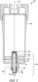
FIG. 2 is a front cross-sectional view of the filter assembly taken along section plane XX' of the view depicted inFIG. 1 , in accordance with embodiments of the present disclosure; -
FIG. 3 is an exploded view of the drain assembly showing a drain body, a retaining cap, a hose barb body and a retaining collar, in accordance with embodiments of the present disclosure; -
FIG. 4 is a front cross-sectional view of the drain assembly taken along section plane YY' ofFIG. 3 , in accordance with embodiments of the present disclosure; -
FIG. 5 is a side cross-sectional view of the drain assembly taken along section plane ZZ' ofFIG. 3 , in accordance with embodiments of the present disclosure; -
FIG. 6 is a top perspective view of the drain assembly without the drain body, in accordance with embodiments of the present disclosure; -
FIG. 7 is a cross-sectional view of the drain assembly without the drain body taken along section plane PP' ofFIG. 6 , in accordance with embodiments of the present disclosure; and -
FIGs. 8 and 9 are different configurations of the hose barb body that can be implemented in the drain assembly, in accordance with embodiments of the present disclosure. - Reference numerals appearing in more than one figure indicate the same or corresponding parts in each of them. References to elements in the singular may also be construed to relate to the plural and vice-versa without limiting the scope of the disclosure to the exact number or type of such elements unless set forth explicitly in the appended claims.
-
FIG. 1 illustrates afilter assembly 100 that can be used to filter contaminants present in a liquid. In an embodiment, thefilter assembly 100 disclosed herein is embodied as a diesel fuel filter. However, in other embodiments, thefilter assembly 100 may be embodied as a gasoline fuel filter or may be used to filter contaminants from other types of liquids including, but not limited to, oils depending on specific requirements of an application. - As shown in
FIGs. 1 and2 , thefilter assembly 100 includes ahousing 102 and adrain assembly 104. Thehousing 102 includes anend plate 106 that is positioned within thehousing 102. Theend plate 106 has adrain port 109 and a threadedreceptacle 108 defined about thedrain port 109. Explanation to thedrain assembly 104 and an inter-relative positioning of its components will now be made in conjunction withFIGs. 2 to 7 . Referring toFIG. 2 , and as best shown in the view ofFIG. 3 , thedrain assembly 104 includes adrain body 110, and anadapter 105 having a retainingcap 124, ahose barb body 136, and aretaining collar 150. - The
drain body 110 defines anelongated passageway 112 that is located along a central axis AA' of thedrain body 110. Thedrain body 110 has afirst portion 114 that is disposed about the central axis AA' and configured to couple with thehousing 102. In an embodiment as shown best in the views ofFIGs. 2 and3 respectively, thefirst portion 114 of thedrain body 110 defines a threadedregion 116 that is structured to engage with the threadedreceptacle 108 of theend plate 106. Thedrain body 110 also has asecond portion 118 that extends away from thefirst portion 114. Thesecond portion 118 has an outer circumference 120 disposed about the central axis AA' andmultiple protrusions 122 that extend laterally away from the outer circumference 120. - Referring to
FIGs. 3 ,4 , and5 , the retainingcap 124 is configured to couple with thesecond portion 118 of thedrain body 110. The retainingcap 124 has aninner wall 126 and anouter wall 132 that is disposed about theinner wall 126 and located in a spaced-apart relation to theinner wall 126. As best shown in the view ofFIGs. 6 and7 , theinner wall 126 defines multipleresilient fingers 128 that are intermittently spaced and disposed about the central axis AA'. With continued reference toFIGs. 6 and7 and as best shown in the views ofFIGs. 4 and5 respectively, theseresilient fingers 128 have ends 130 that extend laterally towards the central axis AA' for capturing therebetween theprotrusions 122 that are located on the outer circumference 120 of thesecond portion 118 of thedrain body 110. - Further, as shown in the views of
FIGs. 5 ,6 , and7 respectively, theouter wall 132 of the retainer cap definesmultiple apertures 134 that are disposed laterally with respect to the central axis AA'. Moreover, anouter surface 133 of theouter wall 132 of the retainingcap 124 hasmultiple recesses 135 defined thereon. Theserecesses 135 are arranged radially about the central axis AA' and are configured to allow a user to grip the retainingcap 124, for example, to allow ease in handling of the retainingcap 124 during an installation onto, or removal from, thedrain body 110 of thedrain assembly 104. - Referring to
FIGs. 3-7 , thehose barb body 136 is rotatably disposed about the central axis AA' and has a taperedportion 138. In an embodiment herein, the taperedportion 138 of thehose barb body 136 has a frustoconical shape. However, in other embodiments, the taperedportion 138 may be configured to exhibit a frustum of a polyhedron, for example, a frustum of a pentagon or a frustum of a hexagon. As shown in the view ofFIGs. 3-5 , the taperedportion 138 is configured to receive at least a portion i.e., thesecond portion 118 of thedrain body 110. - The tapered
portion 138 also defines alip 142 at anend 140 thereof. As shown best in the views ofFIGs. 4-7 , thislip 142 is disposed proximal to theends 130 of theresilient fingers 128 of the retainingcap 124. In an exemplary embodiment, thelip 142 of thehose barb body 136 is located in the range of, for example, 0.1-2.0 millimeters away from theends 130 of theresilient fingers 128 of the retainingcap 124. - The
hose barb body 136 also has acylindrical portion 144 that extends from the taperedportion 138. Referring toFIG. 3 , thecylindrical portion 144 has anouter circumference 146 that is configured to allow selective coupling of ahose 148 thereon. In an embodiment as shown in the views ofFIGs. 3-7 respectively, theouter circumference 146 of thecylindrical portion 144 of thehose barb body 136 definesbarbs 147 that are configured to allow coupling of thehose 148 thereon. - With continued reference to
FIGs. 3-7 , the retainingcollar 150 is disposed about the central axis AA', and as best shown in the views ofFIGs. 4 ,5 , and7 respectively, the retainingcollar 150 has ashoulder 154 that is disposed proximal to anunderside 156 of thelip 142 of thehose barb body 136. Theshoulder 154 is configured to bear thehose barb body 136 thereon. The retainingcollar 150 also has multipleresilient tabs 158 that are upstanding from theshoulder 154. Theseresilient tabs 158 have ends 160 that laterally extend away from the central axis AA' for engaging with theapertures 134 that are defined in theouter wall 132 of the retainingcap 124. - In an additional embodiment herein, the
drain assembly 104 may further include a seal (not shown). This seal may be disposed between thelip 142 of thehose barb body 136 and theends 130 of the resilient fingers associated with the retainingcap 124. This seal would be configured to prevent leakage between mating surfaces of thedrain assembly 104. - In an embodiment as shown in
FIGs. 8 and 9 , thecylindrical portion 144 of thehose barb body 136 may be disposed at a pre-determined angle α relative to the taperedportion 138 of thehose barb body 136. For instance, in the exemplary view ofFIG. 8 , this pre-determined angle α may be 135 degrees while in the exemplary view ofFIG. 9 , the pre-determined angle α may be 90 degrees. Although 135 degrees and 90 degrees have been disclosed herein, any suitable angle may be implemented for disposing thecylindrical portion 144 relative to the taperedportion 138 and facilitating the connection of thehose 148 to thehose barb body 136 depending on specific requirements of an application. - In an embodiment herein, each of the
drain body 110, the retainingcap 124, thehose barb body 136, and the retainingcollar 150 may be made of a thermoplastic, for example, Polyvinyl Chloride (PVC), Low-density polyethylene (LDPE), or a High-density polyethylene (HDPE). Alternatively, each of thedrain body 110, the retainingcap 124, thehose barb body 136, and the retainingcollar 150 may be made of a metal, for example, brass, stainless steel, or other metals commonly known to persons skilled in the art. - Various embodiments disclosed herein are to be taken in the illustrative and explanatory sense, and should in no way be construed as limiting of the present disclosure. All joinder references (e.g., associated, provided, connected, coupled and the like) are only used to aid the reader's understanding of the present disclosure, and may not create limitations, particularly as to the position, orientation, or use of the assemblies disclosed herein. Therefore, joinder references, if any, are to be construed broadly. Moreover, such joinder references do not necessarily infer that two elements are directly connected to each other.
- Additionally, all numerical terms, such as, but not limited to, "first", "second", or any other ordinary and/or numerical terms, should also be taken only as identifiers, to assist the reader's understanding of the various elements of the present disclosure, and may not create any limitations, particularly as to the order, or preference, of any element relative to or over another element. The above described implementation does not in any way limit the scope of the present disclosure. Therefore, it is to be understood although some features are shown or described to illustrate the use of the present disclosure in the context of functional segments, such features may be omitted from the scope of the present disclosure without departing from the spirit of the present disclosure as defined in the appended claims.
- The present disclosure has applicability for use and implementation in providing a drain assembly for a housing of a filter assembly. With use of the present disclosure, manufacturers of filter assemblies can provide aftermarket drain assemblies that can be retrofit onto housings of existing filter assemblies. The
adapter 105 disclosed herein includes thehose barb body 136 that is axially secured between the retainingcap 124 and the retainingcollar 150 while thehose barb body 136 is capable of rotating about the central axis AA'. This rotatable movement of thehose barb body 136 allows maintenance personnel to rotate thehose 148 that is coupled to thesecond portion 118 of thehose barb body 136 during service routines. - Further, it is hereby envisioned that by providing the rotatable
hose barb body 136, a possibility of kinks in thehose 148 may be reduced as thehose barb body 136 now rotates together with thehose 148 and a separate bending of thehose 148 relative to thehose barb body 136 may no longer be required. Furthermore, it is hereby also envisioned that the substantially axial configuration of thedrain body 110, the retainingcap 124, thehose barb body 136, and the retainingcollar 150 shown inFIGs. 3 through 7 provides an uninterrupted flow passage to the fluid and any contaminants draining out of thehousing 102. Moreover, in embodiments where thedrain body 110, the retainingcap 124, thehose barb body 136, and the retainingcollar 150 are made of a thermoplastic, these components can be manufactured in a relatively inexpensive manner while also mitigating the possibility of failure from thermal effects. - While aspects of the present disclosure have been particularly shown and described with reference to the embodiments above, it will be understood by those skilled in the art that various additional embodiments may be contemplated by the modification of the disclosed assemblies without departing from the spirit and scope of what is disclosed. Such embodiments should be understood to fall within the scope of the present disclosure as determined based upon the claims and any equivalents thereof.
Claims (15)
- An adapter (105) for fluidly coupling a hose (148) to a housing (102) of a filter assembly (100) having a drain body (110) connected to a drain port (109) of the housing (102), the adapter (105) comprising:a retaining cap (124) disposed about a central axis (AA') and configured to couple with the drain body (110), the retaining cap (124) having:an inner wall (126) defining a plurality of intermittently spaced resilient fingers (128) disposed about the central axis (AA'), the plurality of resilient fingers (128) having ends (130) extending laterally towards the central axis (AA') for capturing therebetween a plurality of protrusions (122) located on an outer circumference (120) of the drain body (110), andan outer wall (132) disposed about the inner wall (126) and located in a spaced-apart relation to the inner wall (126), the outer wall (132) defining a plurality of apertures (134) disposed laterally with respect to the central axis (AA');a hose barb body (136) disposed rotatably about the central axis (AA'), the hose barb body (136) having:a tapered portion (138) configured to receive at least a portion of the drain body (110) therein, the tapered portion (138) defining a lip (142) at an end (140) thereof, the lip (142) disposed proximal to the ends (130) of the resilient fingers (128) of the retaining cap (124), anda cylindrical portion (144) extending from the tapered portion (138), the cylindrical portion (144) having an outer circumference (146) configured to allow selective coupling of a hose (148) thereon; anda retaining collar (150) disposed about the central axis (AA'), the retaining collar (150) having:a shoulder (154) disposed proximal to an underside (156) of the lip (142) of the hose barb body (136), the shoulder (154) configured to bear the hose barb body (136) thereon, anda plurality of resilient tabs (158) upstanding from the shoulder (154), the plurality of resilient tabs (158) having ends (160) laterally extending away from the central axis (AA') for engaging with the plurality of apertures (134) defined in the outer wall (132) of the retaining cap (124).
- The adapter (105) of claim 1, wherein the lip (142) of the hose barb body (136) is positioned in the range of 0.1-2.0 millimeters away from the ends (130) of the resilient fingers (128) of the retaining cap (124).
- The adapter (105) of claim 1, wherein the outer wall (132) of the retaining cap (124) has an outer surface (133) defining a plurality of recesses (135) arranged radially about the central axis (AA'), the plurality of recesses (135) configured to allow a user to grip the retaining cap (124).
- The adapter (105) of claim 1, wherein the tapered portion (138) of the hose barb body (136) has a frustoconical shape.
- The adapter (105) of claim 1, wherein each of the retaining cap (124), the hose barb body (136), and the retaining collar (150) are made from one of a thermoplastic and a metal.
- The adapter (105) of claim 1, wherein the outer circumference (146) of the cylindrical portion (144) of the hose barb body (136) defines barbs (147) that are configured to allow coupling of the hose (148) thereon.
- The adapter (105) of claim 1 further comprising a seal (162) disposed between the lip (142) of the hose barb body (136) and the ends (130) of the resilient fingers (128) associated with the retaining cap (124).
- A drain assembly (104) for a housing (102) of a filter assembly (100), the drain assembly (104) comprising:a drain body (110) defining an elongated passageway (112) along a central axis (AA') of the drain body (110), the drain body (110) having:a first portion (114) disposed about the central axis (AA') and configured to couple with the housing (102), anda second portion (118) extending away from the first portion (114), the second portion (118) having an outer circumference (120) disposed about the central axis (AA') and a plurality of protrusions (122) extending laterally away from the outer circumference (120);a retaining cap (124) coupled to the second portion (118) of the drain body (110), the retaining cap (124) having:an inner wall (126) defining a plurality of intermittently spaced resilient fingers (128) disposed about the central axis (AA'), the plurality of resilient fingers (128) having ends (130) extending laterally towards the central axis (AA') for capturing therebetween the plurality of protrusions (122) located on the outer circumference (120) of the second portion (118) of the drain body (110), andan outer wall (132) disposed about the inner wall (126) and located in a spaced-apart relation to the inner wall (126), the outer wall (132) defining a plurality of apertures (134) disposed laterally with respect to the central axis (AA');a hose barb body (136) rotatably disposed about the central axis (AA'), the hose barb body (136) having:a tapered portion (138) configured to receive the second portion (118) of the drain body (110), the tapered portion (138) defining a lip (142) at an end (140) thereof, the lip (142) disposed proximal to the ends (130) of the resilient fingers (128) of the retaining cap (124), anda cylindrical portion (144) extending from the tapered portion (138), the cylindrical portion (144) having an outer circumference (146) configured to allow selective coupling of a hose (148) thereon; anda retaining collar (150) disposed about the central axis (AA'), the retaining collar (150) having:a shoulder (154) disposed proximal to an underside (156) of the lip (142) of the hose barb body (136), the shoulder (154) configured to bear the hose barb body (136) thereon, anda plurality of resilient tabs (158) upstanding from the shoulder (154), the plurality of resilient tabs (158) having ends (160) laterally extending away from the central axis (AA') for engaging with the plurality of apertures (134) defined in the outer wall (132) of the retaining cap (124).
- The drain assembly (104) of claim 8, wherein the lip (142) of the hose barb body (136) is positioned in the range of 0.1-2.0 millimeters away from the ends (130) of the resilient fingers (128) of the retaining cap (124).
- The drain assembly (104) of claim 8, wherein the first portion (114) of the drain body (110) defines a threaded region (116) structured to engage with a threaded receptacle (108) defined in an end plate (106) positioned within the housing (102).
- The drain assembly (104) of claim 8, wherein the outer wall (132) of the retaining cap (124) has an outer surface (133) defining a plurality of recesses (135) arranged radially about the central axis (AA'), the plurality of recesses (135) configured to allow a user to grip the retaining cap (124).
- The drain assembly (104) of claim 8, wherein the tapered portion (138) of the hose barb body (136) has a frustoconical shape.
- The drain assembly (104) of claim 8, wherein each of the drain body (110), the retaining cap (124), the hose barb body (136), and the retaining collar (150) are made from one of a thermoplastic and a metal.
- The drain assembly (104) of claim 8, wherein the outer circumference (146) of the cylindrical portion (144) of the hose barb body (136) defines barbs (147) that are configured to allow coupling of the hose (148) thereon.
- The drain assembly (104) of claim 8 further comprising a seal (162) disposed between the lip (142) of the hose barb body (136) and the ends (130) of the resilient fingers (128) associated with the retaining cap (124).
Applications Claiming Priority (1)
| Application Number | Priority Date | Filing Date | Title |
|---|---|---|---|
| US16/177,580 US10729996B2 (en) | 2018-11-01 | 2018-11-01 | Drain assembly for a housing of a filter assembly |
Publications (1)
| Publication Number | Publication Date |
|---|---|
| EP3646928A1 true EP3646928A1 (en) | 2020-05-06 |
Family
ID=68281255
Family Applications (1)
| Application Number | Title | Priority Date | Filing Date |
|---|---|---|---|
| EP19203712.5A Withdrawn EP3646928A1 (en) | 2018-11-01 | 2019-10-16 | Hose adapter and drain assembly for a housing of a filter assembly |
Country Status (2)
| Country | Link |
|---|---|
| US (1) | US10729996B2 (en) |
| EP (1) | EP3646928A1 (en) |
Families Citing this family (3)
| Publication number | Priority date | Publication date | Assignee | Title |
|---|---|---|---|---|
| US20220016584A1 (en) * | 2020-07-17 | 2022-01-20 | Delaware Capital Formation, Inc. | Air gap eductor and method of making same |
| US12331857B2 (en) | 2022-08-15 | 2025-06-17 | Caterpillar Inc. | Apparatus with interlocking surfaces to secure angle of hydraulic coupling connections |
| WO2024168263A1 (en) * | 2023-02-10 | 2024-08-15 | Ohnoh2O, Llc | Drain funnel adapter |
Citations (5)
| Publication number | Priority date | Publication date | Assignee | Title |
|---|---|---|---|---|
| EP0289188A2 (en) * | 1987-04-24 | 1988-11-02 | Parker Hannifin Corporation | Fluid filter drain assembly |
| DE9311759U1 (en) * | 1993-08-06 | 1993-11-11 | W. Kottmann Nachf. Gebr. Gosla GmbH, 58642 Iserlohn | Nipple for the rotatable connection of a hose |
| US20130093180A1 (en) * | 2011-10-18 | 2013-04-18 | Neoperl Gmbh | Detachable plug connection |
| US20150202552A1 (en) * | 2014-01-23 | 2015-07-23 | Caterpillar Inc. | Liquid filter drain with integral air vent |
| WO2016149739A1 (en) | 2015-03-25 | 2016-09-29 | Filter Pod Pty Ltd | A filter for the filtration of liquids |
Family Cites Families (9)
| Publication number | Priority date | Publication date | Assignee | Title |
|---|---|---|---|---|
| US3849806A (en) | 1973-08-17 | 1974-11-26 | B Strickland | Shampoo bowl assembly |
| US4655398A (en) | 1983-12-19 | 1987-04-07 | Goodyear Aerospace Corporation | Spraying apparatus for in situ formation of vehicle fuel tanks |
| JPS6472916A (en) | 1987-09-11 | 1989-03-17 | Nittetsu Mining Co Ltd | Production of baddeleyite type calcium carbonate |
| US8157997B2 (en) * | 2007-10-17 | 2012-04-17 | Caterpillar Inc. | Canister filter system with drain that cooperates with filter element |
| AU2010358557B2 (en) | 2010-08-06 | 2014-12-18 | General Ecology, Inc. | Apparatus for filtering and/or conditioning and/or purifying a fluid such as water |
| US8877055B2 (en) * | 2010-10-13 | 2014-11-04 | Baldwin Filters, Inc. | Filter having drain valve with mechanical lock |
| JP5992230B2 (en) | 2012-06-30 | 2016-09-14 | 株式会社環境施設 | Swivel joint |
| US9151424B2 (en) * | 2013-10-24 | 2015-10-06 | Caterpillar Inc. | Connector for connecting hose coupler to drain knob |
| CN206159734U (en) | 2016-10-26 | 2017-05-10 | 江苏必得科技股份有限公司 | Prevent wind husky comdenstion water drainage joint |
-
2018
- 2018-11-01 US US16/177,580 patent/US10729996B2/en not_active Expired - Fee Related
-
2019
- 2019-10-16 EP EP19203712.5A patent/EP3646928A1/en not_active Withdrawn
Patent Citations (5)
| Publication number | Priority date | Publication date | Assignee | Title |
|---|---|---|---|---|
| EP0289188A2 (en) * | 1987-04-24 | 1988-11-02 | Parker Hannifin Corporation | Fluid filter drain assembly |
| DE9311759U1 (en) * | 1993-08-06 | 1993-11-11 | W. Kottmann Nachf. Gebr. Gosla GmbH, 58642 Iserlohn | Nipple for the rotatable connection of a hose |
| US20130093180A1 (en) * | 2011-10-18 | 2013-04-18 | Neoperl Gmbh | Detachable plug connection |
| US20150202552A1 (en) * | 2014-01-23 | 2015-07-23 | Caterpillar Inc. | Liquid filter drain with integral air vent |
| WO2016149739A1 (en) | 2015-03-25 | 2016-09-29 | Filter Pod Pty Ltd | A filter for the filtration of liquids |
Also Published As
| Publication number | Publication date |
|---|---|
| US10729996B2 (en) | 2020-08-04 |
| US20200139277A1 (en) | 2020-05-07 |
Similar Documents
| Publication | Publication Date | Title |
|---|---|---|
| EP3646928A1 (en) | Hose adapter and drain assembly for a housing of a filter assembly | |
| EP3467367B1 (en) | Anti-tamper permanent quick connect coupling device | |
| CN104955512B (en) | For controlling the device of flow of fluid | |
| EP3604883B1 (en) | Resinous pipe joint | |
| CA2928872C (en) | Self-locking push-to-connect insert | |
| WO2015130600A1 (en) | Clam shell push-to-connect assembly | |
| US9638360B2 (en) | Leak detection O-ring | |
| KR20090056148A (en) | Quick connectors | |
| EP2542812B1 (en) | Flanged fitting for use with tubing containment system | |
| US20150130184A1 (en) | Barbed hose end fitting apparatus for ptfe core hose | |
| US20080079258A1 (en) | Irrigation sprinkler adapter | |
| US20070126232A1 (en) | Fluid coupling with non-protective coated endform tip | |
| EP4279788B1 (en) | Push-fitting | |
| US20220288512A1 (en) | Filter element with biplanar o-ring | |
| CN112984251B (en) | Connection arrangement for fluid transfer interface | |
| CN103574195B (en) | Hydraulic suction line | |
| US10865915B2 (en) | Fire hydrant nozzle | |
| US20090058082A1 (en) | Two-part quick connect retention attachment for flexible tubing in a water supply system | |
| JP5566668B2 (en) | Pipe fitting | |
| EP4425026A1 (en) | A pipe part and a connection between two pipe parts | |
| JP6913541B2 (en) | Connection structure of fluid equipment | |
| EP3051151B1 (en) | Retrofittable flow-through connector assembly for an expansion tank apparatus | |
| JP2020094621A (en) | Medium tool | |
| WO2014153186A1 (en) | Apparatuses and methods for providing quick-connections with retaining features | |
| HK1180385B (en) | Flanged fitting for use with tubing containment system |
Legal Events
| Date | Code | Title | Description |
|---|---|---|---|
| PUAI | Public reference made under article 153(3) epc to a published international application that has entered the european phase |
Free format text: ORIGINAL CODE: 0009012 |
|
| STAA | Information on the status of an ep patent application or granted ep patent |
Free format text: STATUS: THE APPLICATION HAS BEEN PUBLISHED |
|
| AK | Designated contracting states |
Kind code of ref document: A1 Designated state(s): AL AT BE BG CH CY CZ DE DK EE ES FI FR GB GR HR HU IE IS IT LI LT LU LV MC MK MT NL NO PL PT RO RS SE SI SK SM TR |
|
| AX | Request for extension of the european patent |
Extension state: BA ME |
|
| RIN1 | Information on inventor provided before grant (corrected) |
Inventor name: MOREHOUSE, DARRELL Inventor name: RODRIGUEZ, JAVIER |
|
| STAA | Information on the status of an ep patent application or granted ep patent |
Free format text: STATUS: REQUEST FOR EXAMINATION WAS MADE |
|
| 17P | Request for examination filed |
Effective date: 20201028 |
|
| RBV | Designated contracting states (corrected) |
Designated state(s): AL AT BE BG CH CY CZ DE DK EE ES FI FR GB GR HR HU IE IS IT LI LT LU LV MC MK MT NL NO PL PT RO RS SE SI SK SM TR |
|
| STAA | Information on the status of an ep patent application or granted ep patent |
Free format text: STATUS: EXAMINATION IS IN PROGRESS |
|
| 17Q | First examination report despatched |
Effective date: 20220119 |
|
| REG | Reference to a national code |
Ref country code: DE Ref legal event code: R079 Free format text: PREVIOUS MAIN CLASS: B01D0036000000 Ipc: F16L0027080000 |
|
| GRAP | Despatch of communication of intention to grant a patent |
Free format text: ORIGINAL CODE: EPIDOSNIGR1 |
|
| STAA | Information on the status of an ep patent application or granted ep patent |
Free format text: STATUS: GRANT OF PATENT IS INTENDED |
|
| RIC1 | Information provided on ipc code assigned before grant |
Ipc: F16L 33/00 20060101ALN20230217BHEP Ipc: B01D 35/16 20060101ALI20230217BHEP Ipc: B01D 35/153 20060101ALI20230217BHEP Ipc: F16L 37/098 20060101ALI20230217BHEP Ipc: F16L 27/08 20060101AFI20230217BHEP |
|
| RIC1 | Information provided on ipc code assigned before grant |
Ipc: F16L 33/00 20060101ALN20230309BHEP Ipc: B01D 35/16 20060101ALI20230309BHEP Ipc: B01D 35/153 20060101ALI20230309BHEP Ipc: F16L 37/098 20060101ALI20230309BHEP Ipc: F16L 27/08 20060101AFI20230309BHEP |
|
| INTG | Intention to grant announced |
Effective date: 20230321 |
|
| STAA | Information on the status of an ep patent application or granted ep patent |
Free format text: STATUS: THE APPLICATION IS DEEMED TO BE WITHDRAWN |
|
| 18D | Application deemed to be withdrawn |
Effective date: 20230601 |