EP3646740A1 - Inspection device for rod-shaped smoking article, production machine for rod-shaped smoking article, and inspection method for rod-shaped smoking article - Google Patents
Inspection device for rod-shaped smoking article, production machine for rod-shaped smoking article, and inspection method for rod-shaped smoking article Download PDFInfo
- Publication number
- EP3646740A1 EP3646740A1 EP17929422.8A EP17929422A EP3646740A1 EP 3646740 A1 EP3646740 A1 EP 3646740A1 EP 17929422 A EP17929422 A EP 17929422A EP 3646740 A1 EP3646740 A1 EP 3646740A1
- Authority
- EP
- European Patent Office
- Prior art keywords
- rod
- smoking article
- inspection
- shaped smoking
- color
- Prior art date
- Legal status (The legal status is an assumption and is not a legal conclusion. Google has not performed a legal analysis and makes no representation as to the accuracy of the status listed.)
- Granted
Links
Images




Classifications
-
- A—HUMAN NECESSITIES
- A24—TOBACCO; CIGARS; CIGARETTES; SIMULATED SMOKING DEVICES; SMOKERS' REQUISITES
- A24C—MACHINES FOR MAKING CIGARS OR CIGARETTES
- A24C5/00—Making cigarettes; Making tipping materials for, or attaching filters or mouthpieces to, cigars or cigarettes
- A24C5/32—Separating, ordering, counting or examining cigarettes; Regulating the feeding of tobacco according to rod or cigarette condition
- A24C5/34—Examining cigarettes or the rod, e.g. for regulating the feeding of tobacco; Removing defective cigarettes
- A24C5/3412—Examining cigarettes or the rod, e.g. for regulating the feeding of tobacco; Removing defective cigarettes by means of light, radiation or electrostatic fields
-
- A—HUMAN NECESSITIES
- A24—TOBACCO; CIGARS; CIGARETTES; SIMULATED SMOKING DEVICES; SMOKERS' REQUISITES
- A24C—MACHINES FOR MAKING CIGARS OR CIGARETTES
- A24C5/00—Making cigarettes; Making tipping materials for, or attaching filters or mouthpieces to, cigars or cigarettes
- A24C5/32—Separating, ordering, counting or examining cigarettes; Regulating the feeding of tobacco according to rod or cigarette condition
- A24C5/34—Examining cigarettes or the rod, e.g. for regulating the feeding of tobacco; Removing defective cigarettes
-
- G—PHYSICS
- G01—MEASURING; TESTING
- G01N—INVESTIGATING OR ANALYSING MATERIALS BY DETERMINING THEIR CHEMICAL OR PHYSICAL PROPERTIES
- G01N21/00—Investigating or analysing materials by the use of optical means, i.e. using sub-millimetre waves, infrared, visible or ultraviolet light
- G01N21/84—Systems specially adapted for particular applications
- G01N21/88—Investigating the presence of flaws or contamination
- G01N21/89—Investigating the presence of flaws or contamination in moving material, e.g. running paper or textiles
- G01N21/892—Investigating the presence of flaws or contamination in moving material, e.g. running paper or textiles characterised by the flaw, defect or object feature examined
-
- G—PHYSICS
- G01—MEASURING; TESTING
- G01N—INVESTIGATING OR ANALYSING MATERIALS BY DETERMINING THEIR CHEMICAL OR PHYSICAL PROPERTIES
- G01N21/00—Investigating or analysing materials by the use of optical means, i.e. using sub-millimetre waves, infrared, visible or ultraviolet light
- G01N21/84—Systems specially adapted for particular applications
- G01N21/88—Investigating the presence of flaws or contamination
- G01N21/95—Investigating the presence of flaws or contamination characterised by the material or shape of the object to be examined
- G01N21/952—Inspecting the exterior surface of cylindrical bodies or wires
Definitions
- the present invention relates to an inspection device for a rod-shaped smoking article, a production machine for the rod-shaped smoking article, and an inspection method for the rod-shaped smoking article.
- a filter used in a smoking article such as a cigarette is diversified.
- a filter that is divided into a plurality of segments and includes a charcoal, a capsule, a center hole, and a sweetener in the respective segments has been well-known.
- a length of each of the segments is variously set to 5 mm to 50 mm.
- Such a filter including the plurality of segments is generally formed from a filter rod including cutout segments that have been aligned, arranged with predetermined intervals, and integrated by a combiner.
- erroneous arrangement of the segments may occur, or a defect may occur on each of the segments as the segment structure becomes more complicated. Accordingly, it is necessary to inspect quality of the segment arrangement in the filter rod and quality of the segments themselves.
- a filter inspection device using a plurality of wavelengths has been well-known.
- Patent Document 1 discloses an inspection device that inspects segment arrangement of a multi-segment filter, and the like.
- the inspection device determines quality of the segment arrangement from reflection characteristics of a laser beam, and the like.
- Patent Document 2 discloses an inspection device that causes an infrared ray to pass through a filter and determines quality of a capsule from difference of transmission characteristics of the filter.
- the infrared ray of a long wavelength range is dispersed after the infrared ray passes through an inspection target, and a plurality of light reception units individually receive the dispersed infrared rays to determine the quality of the capsule.
- the capsule is diversified, and colors of the capsules are changed for respective brands of cigarettes in terms of traceability. Therefore, not only content liquid used in the capsules but also coloring matters thereof are diversified, and the optical characteristics of the capsules are varied for each of the capsules.
- threshold setting of the optical characteristics used in the inspection is different depending on the type of the capsule, and complicated threshold setting is necessary depending on the capsule. Furthermore, an appropriate inspection may not be performed depending on the type of the capsule.
- an inspection device that can perform excellent inspection without requiring the complicated threshold setting and the complicated device configuration for spectroscopy and the like irrespective of the type, in particular, the color of inspection targets when a cigarette and a rod-shaped smoking article including a tobacco rod are widely handled as inspection targets in addition to a filter of the cigarette and the filter rod obtained in the manufacturing process thereof.
- the present invention is made in consideration of such issues, and an object of the present invention is to provide an inspection device for a rod-shaped smoking article, a production machine for the rod-shaped smoking article, and an inspection method for the rod-shaped smoking article that each can perform excellent inspection without requiring the complicated threshold setting and the complicated device configuration for spectroscopy and the like irrespective of the type, in particular, the color of inspection target.
- an aspect of the present invention is directed to an inspection device for a rod-shaped smoking article, including: a plurality of light sources configured to generate light beams with different wavelength distributions; an adjuster configured to form an inspection beam from the light beams generated by the respective light sources; an irradiation unit configured to irradiate the rod-shaped smoking article with the inspection beam formed by the adjuster; a light receiver configured to receive a measurement beam that is obtained when the inspection beam applied from the irradiation unit acts on the rod-shaped smoking article; and a determination unit configured to determine quality of the rod-shaped smoking article based on the measurement beam received by the light receiver.
- the adjuster adjusts a color of the inspection beam by mixing the light beams generated by the respective light sources.
- An aspect of the present invention is directed to a production machine for a rod-shaped smoking article including the above-described inspection device, and the production machine includes a conveyance drum configured to convey the rod-shaped smoking article.
- the conveyance drum includes a cylindrical core that internally includes a suction source and the irradiation unit, and a drum shell that covers the cylindrical core and is disposed to be rotatable with respect to the cylindrical core.
- the cylindrical core includes a communication port that makes the suction source and the drum shell communicate with each other in a circumferential direction, and a first irradiation port at which the irradiation unit is positioned.
- the drum shell includes a plurality of holding grooves that are arranged with intervals in the circumferential direction and are each configured to hold the rod-shaped smoking article, a suction hole that is opened on a bottom wall of each of the holding grooves and communicates with the communication port along with rotation of the drum shell, and a second irradiation port that is opened on the bottom wall of each of the holding grooves.
- the irradiation unit irradiates the rod-shaped smoking article held by the corresponding holding groove with the inspection beam.
- An aspect of the present invention is directed to an inspection method for a rod-shaped smoking article, including: a light generation step of generating a plurality of light beams with different wavelength distributions; an adjustment step of forming an inspection beam from the plurality of light beams; an irradiation step of irradiating the rod-shaped smoking article with the inspection beam; a light reception step of receiving a measurement beam obtained when the applied inspection beam acts on the rod-shaped article; and a determination step of determining quality of the rod-shaped article based on the measurement beam.
- the adjustment step includes a color adjustment process of adjusting a color of the inspection beam by mixing the light beams generated in the light generation step.
- the inspection device for the rod-shaped smoking article the production machine for the rod-shaped smoking article, and the inspection method for the rod-shaped smoking article of the present invention, it is possible to perform excellent inspection of the rod-shaped smoking article without requiring the complicated threshold setting and the complicated device configuration for spectroscopy and the like irrespective of the type, in particular, the color of the inspection target.
- FIG. 1 is a block diagram illustrating an outline of a production machine for a multi-segment filter rod for a cigarette that is an example of the rod-shaped smoking article.
- a production machine 1 includes a combiner 2 on an upstream side.
- the combiner 2 aligns material rods (segments) cut out from a plurality of types of filter materials, in one line based on a predetermined arrangement, to form a large number of continuous bodies arranged with predetermined intervals, and sequentially supplies these continuous bodies to a winding section 4 on a subsequent stage.
- the continuous bodies according to the present embodiment include two material rods (segments) R1 and R2 that are alternately arranged, and two capsules C are separately embedded in each of the material rods R2.
- a plane material rod, a charcoal material rod, a hydrotalcite material rod, or the like is used as the material rods R1 and R2.
- the plane material rod is formed by wrapping filter fiber bundle of cellulose diacetate with wrapping paper.
- the charcoal material rod is obtained by adding activated charcoal particles to the plane material rod.
- the hydrotalcite material rod is obtained by adding hydrotalcite compound particles to the plane material rod.
- Each of the capsules C is a destroyable shell filled with content liquid.
- the content liquid includes, for example, a flavoring ingredient and edible oil (e.g., fatty acid triglyceride) as a solvent in which the flavoring ingredient is dissolved.
- the wrapping paper used for the material rods R1 and R2 may be made different in opacity (optical transparency) by changing, for example, an addition amount of a filler (e.g., calcium carbonate).
- the winding section 4 includes a configuration similar to a configuration of a winding section of a cigarette production machine.
- the winding section 4 continuously wraps the above-described supplied continuous bodies by a forming paper in a process in which the above-described supplied continuous bodies are traveled by a garniture tape together with the forming paper, thereby forming a rod-shaped intermediate product I.
- the intermediate product I is sent out from the winding section 4 to a cutting section 6 on the subsequent stage.
- the intermediate product I is cut to individual multi-segment filter rods MF (hereinafter, also simply referred to as filter rods MF) each having a predetermined length when passing through the cutting section 6.
- the filter rods MF are sent out from the cutting section 6 to an unillustrated kicker.
- the cutting section 6 internally includes a rotary knife, and intermittently cuts the material rods R1 arranged in the intermediate product I, every other rod R1, at a center as a cut position (illustrated by dashed line).
- half bodies R1h of the material rod R1 are positioned at respective ends of each of the filter rod MF, and the material rod R2, the material rod R1, and the material rod R2 are sequentially positioned between the half bodies R1h.
- the filter rods MF each formed in the above-described manner are sequentially sent from the kicker to a conveyance section 8.
- the conveyance section 8 includes a conveyance drum line 10.
- the conveyance drum line 10 conveys the filter rods MF in a direction intersecting with a traveling direction of the intermediate product I, and supplies the filter rods MF to an unillustrated belt conveyer disposed on the subsequent stage of the conveyance drum line 10. Thereafter, the filter rods MF on the belt conveyer are supplied to a filter attachment 12 on the subsequent stage.
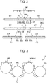
- FIG. 2 is a diagram illustrating an outline of a production process of a filter and a filter cigarette performed by the filter attachment 12.
- the filter attachment 12 cuts one filter rod MF illustrated by a dashed line at the center, to form a filter plug MP.
- the half bodies R1h are positioned at respective ends of the filter plug MP, and the material rod R2 is positioned between the half bodies R1h.
- the filter attachment 12 provides cigarettes CT on the respective ends of the individually-formed filter plug MP, and connects them by winding of a tip paper TP, thereby forming a double filter cigarette DFC.
- the double filter cigarette DFC is cut at a center of the filter plug MP illustrated by a dashed line, namely, at the center of the material rod R2, to form individual filter cigarette FC.
- the filter of the filter cigarette FC is formed as a double filter in which the material half body R1h is adjacent to the material half body R2h of the material rod R2 as a mouthpiece end.
- One capsule C is embedded in the material half body R2h as the mouthpiece end.
- FIG. 3 is a schematic diagram illustrating an example of the conveyance drum line 10 of the conveyance section 8.
- the conveyance drum line 10 includes, for example, four connected conveyance drums 10A to 10D.
- the filter rods MF are sequentially conveyed while being transferred to the adjacent conveyance drums 10A to 10D.
- the conveyance drum 10A that is located at a start end of the conveyance drum line 10 is configured as a catch drum.
- the catch drum receives the filter rods MF that are intermittently sent out through the kicker, and conveys the received filter rods MF to the next conveyance drum 10B, during rotation.
- the filter rods MF are sequentially conveyed from the conveyance drum 10A as the catch drum to the adjacent conveyance drums 10B to 10D while being transferred to the adjacent conveyance drums 10B to 10D.
- the filter rods MF are supplied to the filter attachment 12.
- the conveyance drum 10C in the conveyance drum line 10 is configured as a removal drum. A defective filter rod MF is removed by the removal drum in the conveyance process by the conveyance drum line 10.
- an inspection device 14 for a rod-shaped smoking article is provided on the conveyance drum line 10 of the conveyance section 8. More specifically, the conveyance drum 10B in the conveyance drum line 10 is also used as a part of the inspection device 14, and the inspection device 14 inspects the filter rods MF.
- FIG. 4 is a configuration diagram of the inspection device 14 provided on the conveyance drum 10B.
- the inspection device 14 includes three light sources 16, an adjuster 18, an irradiation unit 20, a detector (light receiver) 22, and a determination unit 24.
- the light sources 16, the detector 22, and the determination unit 24 are disposed outside the conveyance drum 10B.
- the three light sources 16 are devices generating LED (light-emitting diode) light beams of, for example, red R, green G, and blue B.
- the red R, the green G, and the blue B are three primary colors of light.
- Wavelength peaks of the LED light beams of the red R, the green G, and the blue B generated from the light sources 16 are 630 nm, 525 nm, and 450 nm, respectively, and the LED light beams of the red R, the green G, and the blue B have different wavelength distributions.
- each of the light sources 16 is configured so as to independently adjust intensity of the corresponding light beam.
- the adjuster 18 forms inspection beam Li from the light beams generated from the light sources 16.
- the irradiation unit 20 irradiates each filter rod MF with the inspection beam Li formed by the adjuster 18.
- the detector 22 receives measurement beam Lm that is obtained when the inspection beam Li applied from the irradiation unit 20 acts on the filter rod MF.
- the detector 22 according to the present embodiment is, for example, a stroboscopic camera that can perform monochromatic imaging, and receives, as the measurement beam Lm, a light beam transmitted through the filter rod MF.
- the determination unit 24 determines quality of the filter rod MF based on the measurement beam Lm received by the detector 22.
- the determination unit 24 is, for example, an image recognition device, and determines the quality of the filter rod MF based on contrast (brightness difference) of a monochrome image captured by the detector 22.
- the adjuster 18 adjusts a color of the inspection beam Li by mixing the light beams generated from the respective light sources 16. More specifically, the adjuster 18 adjusts the color of the inspection beam Li by causing the respective light sources 16 to adjust the intensity of the light beams generated from the respective light sources 16.
- the conveyance drum 10B includes a fixed cylindrical core 26, and a cylindrical drum shell 28 that is disposed so as to be rotatable with respect to the cylindrical core 26 and covers the cylindrical core 26 on the outside of the cylindrical core 26.
- a suction source 30 and the above-described irradiation unit 20 are disposed inside the cylindrical core 26.
- the cylindrical core 26 includes a communication port 32 that makes the suction source 30 and the drum shell 28 communicate with each other in a circumferential direction, and a first irradiation port 34 at which the irradiation unit 20 is positioned. As illustrated by an alternate long and two short dashes line in FIG. 4 , the communication port 32 is provided over a predetermined range in the circumferential direction.
- the drum shell 28 includes a plurality of holding grooves 36 that are arranged with intervals in the circumferential direction, and a suction hole 38 is opened on a bottom wall of each of the holding grooves 36. Each of the holding grooves 36 is positioned in a formation range of the communication port 32 along with rotation of the drum shell 28.
- the communication port 32 communicates with the suction hole 38.
- the filter rod MF is sucked to and held by each of the holding grooves 36 by suction of air by the suction source 30 through the suction hole 38, and the filter rod MF is transferred from the conveyance drum 10A to the conveyance drum 10B.
- the communication port 32 and the suction hole 38 are put into a non-communication state.
- the irradiation unit 20 irradiates the filter rod MF held by the corresponding holding groove 36, with the inspection beam L1 at this timing, and the filter rod MF is inspected.
- FIG. 5 is a diagram illustrating a part of the conveyance drum 10B as viewed from the detector 22 side.
- FIG. 5 illustrates a state where the filter rod MF is sucked to and held by each of the holding grooves 36.
- Each of the holding grooves 36 has a long groove shape extending in a height direction of the cylindrical drum shell 28, and each of the suction holes 38 has a long hole shape extending in the height direction of the drum shell 28 on the bottom wall of each of the holding grooves 36.
- the suction hole 38 of the drum shell 28 is positioned so as to be overlapped with the first irradiation port 34 of the cylindrical core 26, along with rotation of the drum shell 28 in an arrow direction, and the irradiation unit 20 irradiates the filter rod MF held by the holding groove 36 at the upper most part, with the inspection beam Li.
- the suction holes 38 of the respective holding grooves 36 are sequentially overlapped with the first irradiation port 34.
- the filter rods MF held by the respective holding grooves 36 are sequentially irradiated with the inspection beam Li, and the filter rods MF are sequentially inspected.
- each of the suction holes 38 according to the present embodiment also has a function as a second irradiation port 40 through which the inspection beam Li applied from the first irradiation port 34 passes, and the second irradiation port 40 is formed as a long hole having an opening length that is longer than or equal to a length of the rod-shaped article. Accordingly, the entire length of the filter rod MF can be irradiated with the inspection beam Li.
- FIG. 6 is a configuration diagram of the adjuster 18.
- the adjuster 18 includes a coupler unit 42, an alignment unit 44, and a propagation section 46 in order in a beam propagation direction.
- the coupler unit 42 includes an optical fiber bundle 48, and the fiber bundle 48 includes three branched bundles 48a connected to the respective light sources 16, and one coupled bundle 48b connected to the alignment unit 44.
- the coupled bundle 48b is disposed so as to uniformize distribution of the optical fibers in each of the branched bundles 48a.
- the coupled bundle 48b is branched into a plurality of bundles and connected to the alignment unit 44.
- the coupled bundle 48b is branched so as to uniformize distribution of the optical fibers in each of the branched bundles 48a.
- the light beam coupled by the coupler unit 42 is aligned and branched into the plurality of light beams without color deviation, and the plurality of light beams is propagated to the alignment unit 44.
- the propagation section 46 propagates the light beams branched by the alignment unit 44 to the irradiation unit 20. More specifically, the propagation section 46 includes a space propagation unit 50, a plurality of irradiation fibers 52, and an irradiation source 54 in order in the beam propagation direction.
- the space propagation unit 50 extends between the alignment unit 44 and the irradiation fibers 52 in a direction intersecting with the beam propagation direction.
- the space propagation unit 50 includes a space 50a and a coupling unit 50b, and propagates light beams by coupling through the space 50a.
- the light beams applied from the alignment unit 44 to the space 50a are received by the coupling unit 50b once, and are then propagated to the irradiation fibers 52.
- the irradiation fibers 52 propagates the light beams branched by the alignment unit 44 to the irradiation unit 20 through the space propagation unit 50.
- FIG. 7 is a diagram illustrating the irradiation unit 20 as viewed from the detector 22 side.
- Terminal ends 52a of the respective irradiation fibers 52 are positioned at the irradiation unit 20, and an assembly of the terminal ends 52a functions as the irradiation source 54 disposed on the irradiation unit 20. More specifically, the respective terminal ends 52a are arranged along a longitudinal direction of the first irradiation port 34, and can be handled as one irradiation source 54 extending in the longitudinal direction.
- the light beams generated from the respective light sources 16 are applied from the irradiation unit 20 in a state where the light beams are mixed by the adjuster 18 having the above-described configuration, without color deviation.
- FIG. 8 is a diagram illustrating a case where dimming plates 56 are used in the adjuster 18 illustrated in FIG. 6 .
- the dimming plates 56 are disposed at the respective ends of the space 50a of the space propagation unit 50 so as to be slidable in the direction intersecting with the beam propagation direction.
- Providing the two dimming plates 56 in the space propagation unit 50 as illustrated in FIG. 8 makes it possible to dim the light beams propagated from the alignment unit 44 to the coupling unit 50b through the space propagation unit 50.
- FIG. 9 is an image when the inspection device 14 inspects the filter rod MF that includes the material rods R1 and R2 wrapped with the wrapping paper different in opacity (optical transparency).
- the image is obtained by imaging the measurement beam Lm by the detector 22, for example, when a red capsule C is used and the inspection beam Li of blue-green color opposite to the red color passes through the filter rod MF.
- the capsule C appears black and has a blurred outline because the capsule C and the inspection beam Li have relationship close to opposite colors.
- a segment boundary B between the material rod R1 and the material rod R2 is unclear and is difficult to be recognized because of the black appearance of the capsule C as well as difference of the opacity (optical transparency) of the wrapping paper used for the material rods R1 and R2. Further, contrast between the material rod R1 and the capsule C is small, and the outline of the capsule C is blurred and expanded. Accordingly, when the inspection device 14 inspects the segment boundary B, the determination unit 24 may erroneously recognize the segment boundary B as the outline of the capsule C in the image recognition, and may determine a good filter rod MF as a defective filter rod.
- FIG. 10 is an image when the inspection device 14 inspects the filter rod MF with the inspection beam Li of a color that is similar to the color of the capsule C.
- the image is obtained by imaging the measurement beam Lm by the detector 22 when the red capsule C is used as with the case in FIG. 9 but the inspection beam Li of the red color passes through the filter rod MF.
- the capsule C appears bright gray because the capsule C and the inspection beam Li have the similar color.
- the determination unit 24 can easily recognize the segment boundary B in the image recognition, and can surely determine quality of the filter rod MF.
- the adjuster 18 adjusts the color of the inspection beam Li by mixing the light beams generated from the respective light sources 16.
- the measurement beam Lm acting on the filter rod MF it is possible to easily adjust the measurement beam Lm acting on the filter rod MF to a color that facilitates determination of the quality of the filter rod MF, by adjusting the color of the inspection beam Li.
- the color of the inspection beam Li More specifically, it is possible to surely recognize the inspection target by adjusting the color of the inspection beam Li based on the inspection target, for example, the position of the segment boundary B, namely, the quality of arrangement of the segments such as the material rods R1 and R2 in the filter rod MF, the quality of each of the segments, and layout and the color of the capsule C.
- the color adjustment of the inspection beam Li can be easily visually performed, it is unnecessary to determine the difference of the optical characteristics of the inspection target with respect to the respective wavelengths of the measurement beam Lm through threshold setting, and it is also unnecessary to analyze signals obtained from the dispersed measurement beams Lm for respective wavelengths. Accordingly, it is possible to perform excellent inspection of the filter rod MF without requiring the complicated threshold setting and a complicated device configuration for spectroscopy and the like, irrespective of the type, in particular, the color of the inspection target.
- the adjuster 18 includes the coupler unit 42 that couples the light beams generated from the respective light sources 16, the alignment unit 44 that branches the light beam coupled by the coupler unit 42 into the plurality of light beams, and the propagation section 46 that propagates the light beams branched by the alignment unit 44 to the irradiation unit 20.
- the propagation section 46 includes the plurality of irradiation fibers 52 that propagate the light beams branched by the alignment unit 44 to the irradiation unit 20, and the irradiation source 54 that includes the terminal ends 52a of the respective irradiation fibers 52 positioned at the irradiation unit 20. Since the adjuster 18 includes such a configuration, it is possible to surely adjust the color of the inspection beam Li, furthermore, the measurement beam Lm.
- the dimming plates 56 are provided on the space propagation unit 50 in the propagation section 46, it is possible to irradiate the filter rod MF with the inspection beam Li having the irradiation width matched to the length of the filter rod MF. This makes it possible to suppress saturation (halation) caused when the detector 22 receives the measurement beam Lm from an unnecessary range where the filter rod MF is not present, for example, in inspection of a short filter rod MF. Accordingly, it is possible to further enhance inspection accuracy of the filter rod MF.
- the irradiation unit 20 irradiates the filter rod MF held by the holding groove 36 of the drum shell 28, with the inspection beam Li.
- the filter rod MF can be inspected with the simpler configuration with use of the conveyance drum 10B provided on the production machine 1 for the filter rod MF.
- suction hole 38 also functions as the second irradiation port 40 through which the inspection beam Li applied from the first irradiation port 34 passes. This makes it possible to inspect the filter rod MF with the simpler configuration without requiring drastic remodeling of the existing conveyance drum 10B.
- the second irradiation port 40 is provided as a long hole having an opening length longer than or equal to the length of the filter rod MF. Therefore, it is possible to irradiate the entire length of the filter rod MF with the inspection beam Li, which makes it possible to further enhance the inspection accuracy of the filter rod MF.
- the inspection device 14 can be easily installed later on the existing production machine 1 for the filter rod MF. This makes it possible to inspect the filter rod MF with the simpler configuration.
- the inspection beam Li is adjusted to the color that allows for recognition of the boundary B between the segments such as the material rods R1 and R2, in the inspection device 14. This makes it possible to easily and surely determine the arrangement quality of the segments such as the material rods R1 and R2.
- the inspection device 14 can reduce influence of the capsule C on the measurement beam Lm by adjusting the inspection beam Li to the color similar to the color of the capsule C. Accordingly, it is possible to more clearly recognize the boundary B between the segments such as the material rods R1 and R2, to recognize the type of each of the segments, and to further enhance the inspection accuracy of the filter rod MF.
- the light sources 16 are devices to generate LED light beams of the three primary colors of light.
- the light sources 16 are not limited thereto, and may generate light beams of different wavelength distributions, more specifically, visible light beams of colors other than the three primary colors.
- two or four or more light sources 16 may be used, or the light sources 16 may be devices each generating, for example, a laser beam other than LED light beam.
- visible light beam is desirable because of easiness of the color adjustment; however, invisible light beams such as ultraviolet rays and infrared rays may be mixed, or only invisible light beam may be used.
- the intensity of the inspection beam Li has been adjusted by each of the light sources 16.
- the intensity of the inspection beam Li may be adjusted by the adjuster 18.
- the detector 22 is a stroboscopic camera that can perform monochromatic imaging; however, the detector 22 may be a camera that can perform color imaging or may be a sensor or the like including the other light receiving function.
- the detector 22 receives the light beam transmitted through the filter rod MF as the measurement beam Lm; however, the measurement beam is not limited thereto.
- the measurement beam Lm may be used as the measurement beam Lm as long as the measurement beam Lm is a light beam obtained when the inspection beam Li acts on the filter rod MF.
- the suction hole 38 provided on the drum shell 28 is also used as the second irradiation port 40; however, the second irradiation port 40 is not limited thereto.
- the second irradiation port 40 may be provided on the bottom wall of each of the holding grooves 36 separately from the suction hole 38. Also in this case, it is possible to achieve the basic performance of the inspection device 14 according to the present embodiment.
- the inspection device 14 inspects the multi-segment filter rod MF for a cigarette.
- the inspection device 14 can recognize not only the position of the boundary B between the segments configuring the filter rod MF but also presence/absence of an object disposed inside the filter rod MF other than the capsule C and the type of the segments themselves.
- the multi-segment filter rod MF may include two or more types of, for example, three or four types of material rods or cavities without being limited to the two types of material rods.
- the inspection device 14 can similarly inspect such a multi-segment filter rod MF.
- the inspection device 14 is widely applicable to inspection of a filter rod other than the multi-segment filter rod, a cigarette, and a rod-shaped smoking article including a tobacco rod.
- the inspection device 14 is provided on the conveyance drum 10B in the conveyance section 8 of the production machine 1 for the filter rod MF.
- the configuration is not limited thereto, and the inspection device 14 may be provided on a conveyance drum configuring the conveyance drum line 10 other than the conveyance drum 10B on the downstream side of the catcher drum.
- the inspection device 14 illustrated in FIG. 4 may be provided on a section other than the conveyance section 8 of the production machine 1 or a production machine for a smoking article other than the production machine 1. Further, the inspection device 14 may be provided as the inspection device 14 for the rod-shaped smoking article, independently of the production machine 1.
- the inspection device 14 can be provided on the conveyance drum line 10 of the production machine 1 or can be independently provided as the inspection device 14 separately from the production machine 1.
- the present invention is widely applicable to inspection of the rod-shaped smoking article by an inspection method described below irrespective of use/disuse of the conveyance drum.
- FIG. 12 is a flowchart illustrating a procedure of the inspection method.
- a plurality of light beams with different wavelength distributions, namely, difference in color are first generated in step S1 (light generation step).
- the inspection beam Li is formed from the plurality of light beams (adjustment step).
- a color adjustment process of adjusting the color of the inspection beam Li by mixing the light beams generated in the light generation step is performed.
- the rod-shaped article is irradiated with the inspection beam Li (irradiation step).
- subsequent step S4 the measurement beam Lm that is obtained when the irradiated inspection beam Li acts on the rod-shaped article is received (light reception step).
- subsequent step S5 quality of the rod-shaped article is determined based on the measurement beam Lm (determination step). The inspection procedure then ends. Note that the rod-shaped article determined as defective in the inspection is appropriately removed. Using such an inspection method can achieve effects similar to the effects achieved when the above-described inspection device 14 is used.
- the color of the inspection beam Li is adjusted by adjusting intensity of each of the light beams generated in the light generation step. Further, in a case where the rod-shaped article is divided into a plurality of segments, quality of the arrangement of the segments can be easily determined by adjusting the color of the inspection beam Li to the color allowing for recognition of the boundary B between the segments in the color adjustment process.
- influence of the capsule C on the measurement beam Lm can be reduced by adjusting the color of the inspection beam Li to the color similar to the object in the color adjustment process. This allows for clear recognition of the boundary B between the segments and further allows for recognition of the type of each of the segments. As a result, it is possible to further enhance the inspection accuracy of the rod-shaped article.
Landscapes
- General Health & Medical Sciences (AREA)
- Health & Medical Sciences (AREA)
- Chemical & Material Sciences (AREA)
- Physics & Mathematics (AREA)
- Analytical Chemistry (AREA)
- Biochemistry (AREA)
- Life Sciences & Earth Sciences (AREA)
- General Physics & Mathematics (AREA)
- Immunology (AREA)
- Pathology (AREA)
- Engineering & Computer Science (AREA)
- Textile Engineering (AREA)
- Toxicology (AREA)
- Investigating Materials By The Use Of Optical Means Adapted For Particular Applications (AREA)
- Investigating Or Analysing Materials By Optical Means (AREA)
Abstract
Description
- The present invention relates to an inspection device for a rod-shaped smoking article, a production machine for the rod-shaped smoking article, and an inspection method for the rod-shaped smoking article.
- In recent years, a filter used in a smoking article such as a cigarette is diversified. For example, a filter that is divided into a plurality of segments and includes a charcoal, a capsule, a center hole, and a sweetener in the respective segments has been well-known. A length of each of the segments is variously set to 5 mm to 50 mm. Such a filter including the plurality of segments is generally formed from a filter rod including cutout segments that have been aligned, arranged with predetermined intervals, and integrated by a combiner.
- In the formed filter rod, erroneous arrangement of the segments may occur, or a defect may occur on each of the segments as the segment structure becomes more complicated. Accordingly, it is necessary to inspect quality of the segment arrangement in the filter rod and quality of the segments themselves. As a device used for the inspection, a filter inspection device using a plurality of wavelengths has been well-known.
-
Patent Document 1 discloses an inspection device that inspects segment arrangement of a multi-segment filter, and the like. The inspection device determines quality of the segment arrangement from reflection characteristics of a laser beam, and the like. - Patent Document 2 discloses an inspection device that causes an infrared ray to pass through a filter and determines quality of a capsule from difference of transmission characteristics of the filter. In the inspection device, the infrared ray of a long wavelength range is dispersed after the infrared ray passes through an inspection target, and a plurality of light reception units individually receive the dispersed infrared rays to determine the quality of the capsule.
-
- Patent Document 1: Japanese Patent Laid-Open No.
2007-89583 - Patent Document 2: Japanese Patent Laid-Open No.
2014-178117 - Most of the existing inspection devices as disclosed in
Patent Documents 1 and 2 each inspects the segment arrangement in the filter rod, and presence/absence and quality of an object such as a capsule and a charcoal in each of the segments based on combination of a plurality of wavelengths in the long wavelength range and difference of optical characteristics of the inspection target to each of the wavelengths. Further, some of the existing inspection devices disperse a measurement beam that has applied to the inspection target and has transmitted through or reflected by the inspection target, by a spectroscope or the like, makes the light beams into signals by different detectors, and analyzes the signals obtained for respective wavelengths, thereby determining quality of the inspection target. Such a configuration requiring the spectroscopy complicates the inspection device, which inevitably leads to an expensive device configuration. - In particular, in recent years, the capsule is diversified, and colors of the capsules are changed for respective brands of cigarettes in terms of traceability. Therefore, not only content liquid used in the capsules but also coloring matters thereof are diversified, and the optical characteristics of the capsules are varied for each of the capsules. Thus, threshold setting of the optical characteristics used in the inspection is different depending on the type of the capsule, and complicated threshold setting is necessary depending on the capsule. Furthermore, an appropriate inspection may not be performed depending on the type of the capsule.
- Accordingly, it is desirable to provide an inspection device that can perform excellent inspection without requiring the complicated threshold setting and the complicated device configuration for spectroscopy and the like irrespective of the type, in particular, the color of inspection targets when a cigarette and a rod-shaped smoking article including a tobacco rod are widely handled as inspection targets in addition to a filter of the cigarette and the filter rod obtained in the manufacturing process thereof.
- The present invention is made in consideration of such issues, and an object of the present invention is to provide an inspection device for a rod-shaped smoking article, a production machine for the rod-shaped smoking article, and an inspection method for the rod-shaped smoking article that each can perform excellent inspection without requiring the complicated threshold setting and the complicated device configuration for spectroscopy and the like irrespective of the type, in particular, the color of inspection target.
- In order to achieve the above object, an aspect of the present invention is directed to an inspection device for a rod-shaped smoking article, including: a plurality of light sources configured to generate light beams with different wavelength distributions; an adjuster configured to form an inspection beam from the light beams generated by the respective light sources; an irradiation unit configured to irradiate the rod-shaped smoking article with the inspection beam formed by the adjuster; a light receiver configured to receive a measurement beam that is obtained when the inspection beam applied from the irradiation unit acts on the rod-shaped smoking article; and a determination unit configured to determine quality of the rod-shaped smoking article based on the measurement beam received by the light receiver. The adjuster adjusts a color of the inspection beam by mixing the light beams generated by the respective light sources.
- An aspect of the present invention is directed to a production machine for a rod-shaped smoking article including the above-described inspection device, and the production machine includes a conveyance drum configured to convey the rod-shaped smoking article. The conveyance drum includes a cylindrical core that internally includes a suction source and the irradiation unit, and a drum shell that covers the cylindrical core and is disposed to be rotatable with respect to the cylindrical core. The cylindrical core includes a communication port that makes the suction source and the drum shell communicate with each other in a circumferential direction, and a first irradiation port at which the irradiation unit is positioned. The drum shell includes a plurality of holding grooves that are arranged with intervals in the circumferential direction and are each configured to hold the rod-shaped smoking article, a suction hole that is opened on a bottom wall of each of the holding grooves and communicates with the communication port along with rotation of the drum shell, and a second irradiation port that is opened on the bottom wall of each of the holding grooves. When the second irradiation port is positioned to be overlapped with the first irradiation port along with the rotation of the drum shell, the irradiation unit irradiates the rod-shaped smoking article held by the corresponding holding groove with the inspection beam.
- An aspect of the present invention is directed to an inspection method for a rod-shaped smoking article, including: a light generation step of generating a plurality of light beams with different wavelength distributions; an adjustment step of forming an inspection beam from the plurality of light beams; an irradiation step of irradiating the rod-shaped smoking article with the inspection beam; a light reception step of receiving a measurement beam obtained when the applied inspection beam acts on the rod-shaped article; and a determination step of determining quality of the rod-shaped article based on the measurement beam. The adjustment step includes a color adjustment process of adjusting a color of the inspection beam by mixing the light beams generated in the light generation step.
- According to the inspection device for the rod-shaped smoking article, the production machine for the rod-shaped smoking article, and the inspection method for the rod-shaped smoking article of the present invention, it is possible to perform excellent inspection of the rod-shaped smoking article without requiring the complicated threshold setting and the complicated device configuration for spectroscopy and the like irrespective of the type, in particular, the color of the inspection target.
-
-
FIG. 1 is a block diagram illustrating an outline of a production machine for a multi-segment filter rod including an inspection device according to an embodiment of the present invention. -
FIG. 2 is a diagram illustrating an outline of a production process of a filter and a filter cigarette performed by a filter attachment inFIG. 1 . -
FIG. 3 is a schematic diagram illustrating an example of a conveyance drum line of a conveyance section inFIG. 1 . -
FIG. 4 is a configuration diagram of an inspection device provided on a conveyance drum inFIG. 3 . -
FIG. 5 is a diagram illustrating a part of the conveyance drum inFIG. 4 as viewed from a detector side. -
FIG. 6 is a configuration diagram of an adjuster inFIG. 4 . -
FIG. 7 is a diagram illustrating an irradiation unit inFIG. 6 as viewed from the detector side. -
FIG. 8 is a diagram illustrating a case where dimming plates are used in the adjuster inFIG. 6 . -
FIG. 9 is an image when the inspection device according to the present embodiment inspects a filter rod MF with an inspection beam of a color similar to a color of a material rod R1. -
FIG. 10 is an image when the inspection device according to the present embodiment inspects the filter rod MF with an inspection beam of a color similar to a color of a capsule C. -
FIG. 11 is a configuration diagram of an inspection device according to a modification of the present invention. -
FIG. 12 is a flowchart to explain a procedure of an inspection method according to the present invention. - An inspection device for a rod-shaped smoking article according to an embodiment of the present invention is described below with reference to drawings.
-
FIG. 1 is a block diagram illustrating an outline of a production machine for a multi-segment filter rod for a cigarette that is an example of the rod-shaped smoking article. Aproduction machine 1 includes a combiner 2 on an upstream side. The combiner 2 aligns material rods (segments) cut out from a plurality of types of filter materials, in one line based on a predetermined arrangement, to form a large number of continuous bodies arranged with predetermined intervals, and sequentially supplies these continuous bodies to a windingsection 4 on a subsequent stage. - The continuous bodies according to the present embodiment include two material rods (segments) R1 and R2 that are alternately arranged, and two capsules C are separately embedded in each of the material rods R2. As the material rods R1 and R2, a plane material rod, a charcoal material rod, a hydrotalcite material rod, or the like is used. The plane material rod is formed by wrapping filter fiber bundle of cellulose diacetate with wrapping paper.
- Further, the charcoal material rod is obtained by adding activated charcoal particles to the plane material rod. The hydrotalcite material rod is obtained by adding hydrotalcite compound particles to the plane material rod. Each of the capsules C is a destroyable shell filled with content liquid. The content liquid includes, for example, a flavoring ingredient and edible oil (e.g., fatty acid triglyceride) as a solvent in which the flavoring ingredient is dissolved. Note that the wrapping paper used for the material rods R1 and R2 may be made different in opacity (optical transparency) by changing, for example, an addition amount of a filler (e.g., calcium carbonate).
- The winding
section 4 includes a configuration similar to a configuration of a winding section of a cigarette production machine. The windingsection 4 continuously wraps the above-described supplied continuous bodies by a forming paper in a process in which the above-described supplied continuous bodies are traveled by a garniture tape together with the forming paper, thereby forming a rod-shaped intermediate product I. The intermediate product I is sent out from the windingsection 4 to acutting section 6 on the subsequent stage. The intermediate product I is cut to individual multi-segment filter rods MF (hereinafter, also simply referred to as filter rods MF) each having a predetermined length when passing through thecutting section 6. The filter rods MF are sent out from thecutting section 6 to an unillustrated kicker. - The
cutting section 6 internally includes a rotary knife, and intermittently cuts the material rods R1 arranged in the intermediate product I, every other rod R1, at a center as a cut position (illustrated by dashed line). As a result, half bodies R1h of the material rod R1 are positioned at respective ends of each of the filter rod MF, and the material rod R2, the material rod R1, and the material rod R2 are sequentially positioned between the half bodies R1h. The filter rods MF each formed in the above-described manner are sequentially sent from the kicker to aconveyance section 8. - The
conveyance section 8 includes aconveyance drum line 10. Theconveyance drum line 10 conveys the filter rods MF in a direction intersecting with a traveling direction of the intermediate product I, and supplies the filter rods MF to an unillustrated belt conveyer disposed on the subsequent stage of theconveyance drum line 10. Thereafter, the filter rods MF on the belt conveyer are supplied to afilter attachment 12 on the subsequent stage. -
FIG. 2 is a diagram illustrating an outline of a production process of a filter and a filter cigarette performed by thefilter attachment 12. Thefilter attachment 12 cuts one filter rod MF illustrated by a dashed line at the center, to form a filter plug MP. The half bodies R1h are positioned at respective ends of the filter plug MP, and the material rod R2 is positioned between the half bodies R1h. Next, thefilter attachment 12 provides cigarettes CT on the respective ends of the individually-formed filter plug MP, and connects them by winding of a tip paper TP, thereby forming a double filter cigarette DFC. - Thereafter, the double filter cigarette DFC is cut at a center of the filter plug MP illustrated by a dashed line, namely, at the center of the material rod R2, to form individual filter cigarette FC. As a result, the filter of the filter cigarette FC is formed as a double filter in which the material half body R1h is adjacent to the material half body R2h of the material rod R2 as a mouthpiece end. One capsule C is embedded in the material half body R2h as the mouthpiece end.
-
FIG. 3 is a schematic diagram illustrating an example of theconveyance drum line 10 of theconveyance section 8. Theconveyance drum line 10 includes, for example, fourconnected conveyance drums 10A to 10D. The filter rods MF are sequentially conveyed while being transferred to theadjacent conveyance drums 10A to 10D. Theconveyance drum 10A that is located at a start end of theconveyance drum line 10 is configured as a catch drum. The catch drum receives the filter rods MF that are intermittently sent out through the kicker, and conveys the received filter rods MF to thenext conveyance drum 10B, during rotation. - Thereafter, the filter rods MF are sequentially conveyed from the
conveyance drum 10A as the catch drum to the adjacent conveyance drums 10B to 10D while being transferred to the adjacent conveyance drums 10B to 10D. As described above, after the filter rods MF are supplied to the belt conveyer, the filter rods MF are supplied to thefilter attachment 12. Further, theconveyance drum 10C in theconveyance drum line 10 is configured as a removal drum. A defective filter rod MF is removed by the removal drum in the conveyance process by theconveyance drum line 10. - In the
production machine 1 according to the present embodiment, aninspection device 14 for a rod-shaped smoking article is provided on theconveyance drum line 10 of theconveyance section 8. More specifically, theconveyance drum 10B in theconveyance drum line 10 is also used as a part of theinspection device 14, and theinspection device 14 inspects the filter rods MF. -
FIG. 4 is a configuration diagram of theinspection device 14 provided on theconveyance drum 10B. Theinspection device 14 includes threelight sources 16, anadjuster 18, anirradiation unit 20, a detector (light receiver) 22, and adetermination unit 24. Thelight sources 16, thedetector 22, and thedetermination unit 24 are disposed outside theconveyance drum 10B. - The three
light sources 16 are devices generating LED (light-emitting diode) light beams of, for example, red R, green G, and blue B. The red R, the green G, and the blue B are three primary colors of light. Wavelength peaks of the LED light beams of the red R, the green G, and the blue B generated from thelight sources 16 are 630 nm, 525 nm, and 450 nm, respectively, and the LED light beams of the red R, the green G, and the blue B have different wavelength distributions. Further, each of thelight sources 16 is configured so as to independently adjust intensity of the corresponding light beam. - The
adjuster 18 forms inspection beam Li from the light beams generated from thelight sources 16. Theirradiation unit 20 irradiates each filter rod MF with the inspection beam Li formed by theadjuster 18. Thedetector 22 receives measurement beam Lm that is obtained when the inspection beam Li applied from theirradiation unit 20 acts on the filter rod MF. Thedetector 22 according to the present embodiment is, for example, a stroboscopic camera that can perform monochromatic imaging, and receives, as the measurement beam Lm, a light beam transmitted through the filter rod MF. - The
determination unit 24 determines quality of the filter rod MF based on the measurement beam Lm received by thedetector 22. Thedetermination unit 24 is, for example, an image recognition device, and determines the quality of the filter rod MF based on contrast (brightness difference) of a monochrome image captured by thedetector 22. - The
adjuster 18 according to the present embodiment adjusts a color of the inspection beam Li by mixing the light beams generated from the respectivelight sources 16. More specifically, theadjuster 18 adjusts the color of the inspection beam Li by causing the respectivelight sources 16 to adjust the intensity of the light beams generated from the respectivelight sources 16. - On the other hand, the
conveyance drum 10B includes a fixedcylindrical core 26, and acylindrical drum shell 28 that is disposed so as to be rotatable with respect to thecylindrical core 26 and covers thecylindrical core 26 on the outside of thecylindrical core 26. Asuction source 30 and the above-describedirradiation unit 20 are disposed inside thecylindrical core 26. - The
cylindrical core 26 includes acommunication port 32 that makes thesuction source 30 and thedrum shell 28 communicate with each other in a circumferential direction, and afirst irradiation port 34 at which theirradiation unit 20 is positioned. As illustrated by an alternate long and two short dashes line inFIG. 4 , thecommunication port 32 is provided over a predetermined range in the circumferential direction. Thedrum shell 28 includes a plurality of holdinggrooves 36 that are arranged with intervals in the circumferential direction, and asuction hole 38 is opened on a bottom wall of each of the holdinggrooves 36. Each of the holdinggrooves 36 is positioned in a formation range of thecommunication port 32 along with rotation of thedrum shell 28. - When each of the holding
grooves 36 is positioned in the formation range of thecommunication port 32, thecommunication port 32 communicates with thesuction hole 38. The filter rod MF is sucked to and held by each of the holdinggrooves 36 by suction of air by thesuction source 30 through thesuction hole 38, and the filter rod MF is transferred from theconveyance drum 10A to theconveyance drum 10B. In contrast, when each of the holdinggrooves 36 holding the filter rod MF deviates from the formation range of thecommunication port 32 along with further rotation of thedrum shell 28, thecommunication port 32 and thesuction hole 38 are put into a non-communication state. - When the
communication port 32 and thesuction hole 38 are in the non-communication state, suction of air by thesuction source 30 through thesuction hole 38 is not performed. Therefore, holding of the filter rod MF by each of the holdinggrooves 36 is canceled, and the filter rod MF is transferred from theconveyance drum 10B to theconveyance drum 10C. - In the
inspection device 14 provided on theconveyance drum 10B, when thesuction hole 38 is positioned so as to be overlapped with thefirst irradiation port 34 along with rotation of thedrum shell 28, theirradiation unit 20 irradiates the filter rod MF held by the corresponding holdinggroove 36, with the inspection beam L1 at this timing, and the filter rod MF is inspected. -
FIG. 5 is a diagram illustrating a part of theconveyance drum 10B as viewed from thedetector 22 side.FIG. 5 illustrates a state where the filter rod MF is sucked to and held by each of the holdinggrooves 36. Each of the holdinggrooves 36 has a long groove shape extending in a height direction of thecylindrical drum shell 28, and each of the suction holes 38 has a long hole shape extending in the height direction of thedrum shell 28 on the bottom wall of each of the holdinggrooves 36. - In
FIG. 5 , in the holdinggroove 36 at the uppermost part, thesuction hole 38 of thedrum shell 28 is positioned so as to be overlapped with thefirst irradiation port 34 of thecylindrical core 26, along with rotation of thedrum shell 28 in an arrow direction, and theirradiation unit 20 irradiates the filter rod MF held by the holdinggroove 36 at the upper most part, with the inspection beam Li. Along with further rotation of thedrum shell 28, the suction holes 38 of the respective holdinggrooves 36 are sequentially overlapped with thefirst irradiation port 34. As a result, the filter rods MF held by the respective holdinggrooves 36 are sequentially irradiated with the inspection beam Li, and the filter rods MF are sequentially inspected. - As described above, each of the suction holes 38 according to the present embodiment also has a function as a
second irradiation port 40 through which the inspection beam Li applied from thefirst irradiation port 34 passes, and thesecond irradiation port 40 is formed as a long hole having an opening length that is longer than or equal to a length of the rod-shaped article. Accordingly, the entire length of the filter rod MF can be irradiated with the inspection beam Li. -
FIG. 6 is a configuration diagram of theadjuster 18. Theadjuster 18 includes acoupler unit 42, analignment unit 44, and apropagation section 46 in order in a beam propagation direction. Thecoupler unit 42 includes anoptical fiber bundle 48, and thefiber bundle 48 includes three branchedbundles 48a connected to the respectivelight sources 16, and one coupledbundle 48b connected to thealignment unit 44. The coupledbundle 48b is disposed so as to uniformize distribution of the optical fibers in each of thebranched bundles 48a. - The coupled
bundle 48b is branched into a plurality of bundles and connected to thealignment unit 44. The coupledbundle 48b is branched so as to uniformize distribution of the optical fibers in each of thebranched bundles 48a. As a result, the light beam coupled by thecoupler unit 42 is aligned and branched into the plurality of light beams without color deviation, and the plurality of light beams is propagated to thealignment unit 44. Thepropagation section 46 propagates the light beams branched by thealignment unit 44 to theirradiation unit 20. More specifically, thepropagation section 46 includes aspace propagation unit 50, a plurality ofirradiation fibers 52, and anirradiation source 54 in order in the beam propagation direction. - The
space propagation unit 50 extends between thealignment unit 44 and theirradiation fibers 52 in a direction intersecting with the beam propagation direction. Thespace propagation unit 50 includes aspace 50a and acoupling unit 50b, and propagates light beams by coupling through thespace 50a. The light beams applied from thealignment unit 44 to thespace 50a are received by thecoupling unit 50b once, and are then propagated to theirradiation fibers 52. In other words, theirradiation fibers 52 propagates the light beams branched by thealignment unit 44 to theirradiation unit 20 through thespace propagation unit 50. -
FIG. 7 is a diagram illustrating theirradiation unit 20 as viewed from thedetector 22 side. Terminal ends 52a of therespective irradiation fibers 52 are positioned at theirradiation unit 20, and an assembly of the terminal ends 52a functions as theirradiation source 54 disposed on theirradiation unit 20. More specifically, the respective terminal ends 52a are arranged along a longitudinal direction of thefirst irradiation port 34, and can be handled as oneirradiation source 54 extending in the longitudinal direction. The light beams generated from the respectivelight sources 16 are applied from theirradiation unit 20 in a state where the light beams are mixed by theadjuster 18 having the above-described configuration, without color deviation. -
FIG. 8 is a diagram illustrating a case where dimmingplates 56 are used in theadjuster 18 illustrated inFIG. 6 . The dimmingplates 56 are disposed at the respective ends of thespace 50a of thespace propagation unit 50 so as to be slidable in the direction intersecting with the beam propagation direction. Providing the two dimmingplates 56 in thespace propagation unit 50 as illustrated inFIG. 8 makes it possible to dim the light beams propagated from thealignment unit 44 to thecoupling unit 50b through thespace propagation unit 50. As a result, it is possible to adjust the irradiation range of the inspection beam Li applied from theirradiation source 54 based on the length of the filter rod MF. -
FIG. 9 is an image when theinspection device 14 inspects the filter rod MF that includes the material rods R1 and R2 wrapped with the wrapping paper different in opacity (optical transparency). The image is obtained by imaging the measurement beam Lm by thedetector 22, for example, when a red capsule C is used and the inspection beam Li of blue-green color opposite to the red color passes through the filter rod MF. In the imaging result at this time, the capsule C appears black and has a blurred outline because the capsule C and the inspection beam Li have relationship close to opposite colors. - In other words, in this case, a segment boundary B between the material rod R1 and the material rod R2 is unclear and is difficult to be recognized because of the black appearance of the capsule C as well as difference of the opacity (optical transparency) of the wrapping paper used for the material rods R1 and R2. Further, contrast between the material rod R1 and the capsule C is small, and the outline of the capsule C is blurred and expanded. Accordingly, when the
inspection device 14 inspects the segment boundary B, thedetermination unit 24 may erroneously recognize the segment boundary B as the outline of the capsule C in the image recognition, and may determine a good filter rod MF as a defective filter rod. - On the other hand,
FIG. 10 is an image when theinspection device 14 inspects the filter rod MF with the inspection beam Li of a color that is similar to the color of the capsule C. The image is obtained by imaging the measurement beam Lm by thedetector 22 when the red capsule C is used as with the case inFIG. 9 but the inspection beam Li of the red color passes through the filter rod MF. In the imaging result at this time, the capsule C appears bright gray because the capsule C and the inspection beam Li have the similar color. - In this case, the capsule C disposed inside the material rod R2 cannot be recognized due to saturation (halation); however, the contrast between the material rod R1 and the capsule C becomes large, and the segment boundary B is clearly recognizable. Accordingly, the
determination unit 24 can easily recognize the segment boundary B in the image recognition, and can surely determine quality of the filter rod MF. - As described above, in the
inspection device 14 according to the present embodiment, theadjuster 18 adjusts the color of the inspection beam Li by mixing the light beams generated from the respectivelight sources 16. As a result, it is possible to easily adjust the measurement beam Lm acting on the filter rod MF to a color that facilitates determination of the quality of the filter rod MF, by adjusting the color of the inspection beam Li. More specifically, it is possible to surely recognize the inspection target by adjusting the color of the inspection beam Li based on the inspection target, for example, the position of the segment boundary B, namely, the quality of arrangement of the segments such as the material rods R1 and R2 in the filter rod MF, the quality of each of the segments, and layout and the color of the capsule C. - Further, since the color adjustment of the inspection beam Li can be easily visually performed, it is unnecessary to determine the difference of the optical characteristics of the inspection target with respect to the respective wavelengths of the measurement beam Lm through threshold setting, and it is also unnecessary to analyze signals obtained from the dispersed measurement beams Lm for respective wavelengths. Accordingly, it is possible to perform excellent inspection of the filter rod MF without requiring the complicated threshold setting and a complicated device configuration for spectroscopy and the like, irrespective of the type, in particular, the color of the inspection target.
- Further, it is possible to adjust the color of the inspection beam Li, furthermore, the measurement beam Lm only by simple operation to adjust the intensity of the light beams generated from the respective
light sources 16. - Further, more specifically, the
adjuster 18 includes thecoupler unit 42 that couples the light beams generated from the respectivelight sources 16, thealignment unit 44 that branches the light beam coupled by thecoupler unit 42 into the plurality of light beams, and thepropagation section 46 that propagates the light beams branched by thealignment unit 44 to theirradiation unit 20. - Further, the
propagation section 46 includes the plurality ofirradiation fibers 52 that propagate the light beams branched by thealignment unit 44 to theirradiation unit 20, and theirradiation source 54 that includes the terminal ends 52a of therespective irradiation fibers 52 positioned at theirradiation unit 20. Since theadjuster 18 includes such a configuration, it is possible to surely adjust the color of the inspection beam Li, furthermore, the measurement beam Lm. - Moreover, since the dimming
plates 56 are provided on thespace propagation unit 50 in thepropagation section 46, it is possible to irradiate the filter rod MF with the inspection beam Li having the irradiation width matched to the length of the filter rod MF. This makes it possible to suppress saturation (halation) caused when thedetector 22 receives the measurement beam Lm from an unnecessary range where the filter rod MF is not present, for example, in inspection of a short filter rod MF. Accordingly, it is possible to further enhance inspection accuracy of the filter rod MF. - Further, when the
suction hole 38 is positioned so as to be overlapped with thefirst irradiation port 34 of thecylindrical core 26 along with rotation of thedrum shell 28, theirradiation unit 20 irradiates the filter rod MF held by the holdinggroove 36 of thedrum shell 28, with the inspection beam Li. As a result, the filter rod MF can be inspected with the simpler configuration with use of theconveyance drum 10B provided on theproduction machine 1 for the filter rod MF. - Further, the
suction hole 38 also functions as thesecond irradiation port 40 through which the inspection beam Li applied from thefirst irradiation port 34 passes. This makes it possible to inspect the filter rod MF with the simpler configuration without requiring drastic remodeling of the existingconveyance drum 10B. - Moreover, the
second irradiation port 40 is provided as a long hole having an opening length longer than or equal to the length of the filter rod MF. Therefore, it is possible to irradiate the entire length of the filter rod MF with the inspection beam Li, which makes it possible to further enhance the inspection accuracy of the filter rod MF. - Since the
light sources 16, thedetector 22, and thedetermination unit 24 are provided outside theconveyance drum 10B, theinspection device 14 can be easily installed later on the existingproduction machine 1 for the filter rod MF. This makes it possible to inspect the filter rod MF with the simpler configuration. - As described with reference to
FIG. 9 and FIG. 10 , in the case where the filter rod MF as the inspection target is divided into the plurality of segments like the material rods R1 and R2, the inspection beam Li is adjusted to the color that allows for recognition of the boundary B between the segments such as the material rods R1 and R2, in theinspection device 14. This makes it possible to easily and surely determine the arrangement quality of the segments such as the material rods R1 and R2. - Further, in the case where the capsule C is disposed inside the filter rod MF, the
inspection device 14 can reduce influence of the capsule C on the measurement beam Lm by adjusting the inspection beam Li to the color similar to the color of the capsule C. Accordingly, it is possible to more clearly recognize the boundary B between the segments such as the material rods R1 and R2, to recognize the type of each of the segments, and to further enhance the inspection accuracy of the filter rod MF. - Although the embodiment of the present invention has been described above, the present invention is not limited to the embodiment, and various modifications can be made without departing from the scope of the present invention.
- For example, in the above-described embodiment, the
light sources 16 are devices to generate LED light beams of the three primary colors of light. However, thelight sources 16 are not limited thereto, and may generate light beams of different wavelength distributions, more specifically, visible light beams of colors other than the three primary colors. Alternatively, two or four or morelight sources 16 may be used, or thelight sources 16 may be devices each generating, for example, a laser beam other than LED light beam. - Further, as the light beam in the embodiment of the present invention, visible light beam is desirable because of easiness of the color adjustment; however, invisible light beams such as ultraviolet rays and infrared rays may be mixed, or only invisible light beam may be used.
- Further, the intensity of the inspection beam Li has been adjusted by each of the
light sources 16. Alternatively, the intensity of the inspection beam Li may be adjusted by theadjuster 18. Further, thedetector 22 is a stroboscopic camera that can perform monochromatic imaging; however, thedetector 22 may be a camera that can perform color imaging or may be a sensor or the like including the other light receiving function. - Further, in the above-described embodiment, the
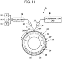
detector 22 receives the light beam transmitted through the filter rod MF as the measurement beam Lm; however, the measurement beam is not limited thereto. For example, as illustrated inFIG. 11 , reflected light beam reflected by the filter rod MF may be used as the measurement beam Lm as long as the measurement beam Lm is a light beam obtained when the inspection beam Li acts on the filter rod MF. - Further, in the above-described embodiment, the
suction hole 38 provided on thedrum shell 28 is also used as thesecond irradiation port 40; however, thesecond irradiation port 40 is not limited thereto. Thesecond irradiation port 40 may be provided on the bottom wall of each of the holdinggrooves 36 separately from thesuction hole 38. Also in this case, it is possible to achieve the basic performance of theinspection device 14 according to the present embodiment. - Further, in the above-described embodiment, the
inspection device 14 inspects the multi-segment filter rod MF for a cigarette. Theinspection device 14, however, can recognize not only the position of the boundary B between the segments configuring the filter rod MF but also presence/absence of an object disposed inside the filter rod MF other than the capsule C and the type of the segments themselves. In addition, the multi-segment filter rod MF may include two or more types of, for example, three or four types of material rods or cavities without being limited to the two types of material rods. Theinspection device 14 can similarly inspect such a multi-segment filter rod MF. Moreover, theinspection device 14 is widely applicable to inspection of a filter rod other than the multi-segment filter rod, a cigarette, and a rod-shaped smoking article including a tobacco rod. - Further, in the above-described embodiment, the
inspection device 14 is provided on theconveyance drum 10B in theconveyance section 8 of theproduction machine 1 for the filter rod MF. However, the configuration is not limited thereto, and theinspection device 14 may be provided on a conveyance drum configuring theconveyance drum line 10 other than theconveyance drum 10B on the downstream side of the catcher drum. - The
inspection device 14 illustrated inFIG. 4 may be provided on a section other than theconveyance section 8 of theproduction machine 1 or a production machine for a smoking article other than theproduction machine 1. Further, theinspection device 14 may be provided as theinspection device 14 for the rod-shaped smoking article, independently of theproduction machine 1. - As described above, the
inspection device 14 can be provided on theconveyance drum line 10 of theproduction machine 1 or can be independently provided as theinspection device 14 separately from theproduction machine 1. In addition, the present invention is widely applicable to inspection of the rod-shaped smoking article by an inspection method described below irrespective of use/disuse of the conveyance drum. -
FIG. 12 is a flowchart illustrating a procedure of the inspection method. When the inspection of the rod-shaped smoking article is started, a plurality of light beams with different wavelength distributions, namely, difference in color are first generated in step S1 (light generation step). In subsequent step S2, the inspection beam Li is formed from the plurality of light beams (adjustment step). In the adjustment step, a color adjustment process of adjusting the color of the inspection beam Li by mixing the light beams generated in the light generation step is performed. In subsequent step S3, the rod-shaped article is irradiated with the inspection beam Li (irradiation step). - In subsequent step S4, the measurement beam Lm that is obtained when the irradiated inspection beam Li acts on the rod-shaped article is received (light reception step). In subsequent step S5, quality of the rod-shaped article is determined based on the measurement beam Lm (determination step). The inspection procedure then ends. Note that the rod-shaped article determined as defective in the inspection is appropriately removed. Using such an inspection method can achieve effects similar to the effects achieved when the above-described
inspection device 14 is used. - More specifically, in the color adjustment process, the color of the inspection beam Li is adjusted by adjusting intensity of each of the light beams generated in the light generation step. Further, in a case where the rod-shaped article is divided into a plurality of segments, quality of the arrangement of the segments can be easily determined by adjusting the color of the inspection beam Li to the color allowing for recognition of the boundary B between the segments in the color adjustment process.
- In a case where an object such as the capsule C is included inside the rod-shaped article, influence of the capsule C on the measurement beam Lm can be reduced by adjusting the color of the inspection beam Li to the color similar to the object in the color adjustment process. This allows for clear recognition of the boundary B between the segments and further allows for recognition of the type of each of the segments. As a result, it is possible to further enhance the inspection accuracy of the rod-shaped article.
-
- 1 Production machine for cigarette multi-segment filter rod (production machine for rod-shaped smoking article)
- 10B Conveyance drum
- 14 Inspection device
- 16 Light source
- 18 Adjuster
- 20 Irradiation unit
- 22 Light receiver
- 24 Determination unit
- 26 Cylindrical core
- 28 Drum shell
- 30 Suction source
- 32 Communication port
- 34 First irradiation port
- 36 Holding groove
- 38 Suction hole
- 40 Second irradiation port
- 44 Alignment unit
- 46 Propagation section
- 42 Coupler unit
- 50 Space propagation unit
- 50a Space
- 52 Irradiation fiber
- 52a Terminal end
- 54 Irradiation source
- 56 Dimming plate
- MF Multi-segment filter rod (rod-shaped smoking article)
- R1, R2 Material rod (segment)
- B Boundary
- C Capsule (object)
- Li Inspection beam
- Lm Measurement beam
Claims (17)
- An inspection device for a rod-shaped smoking article, comprising:a plurality of light sources configured to generate light beams with different wavelength distributions;an adjuster configured to form an inspection beam from the light beams generated by the respective light sources;an irradiation unit configured to irradiate the rod-shaped smoking article with the inspection beam formed by the adjuster;a light receiver configured to receive a measurement beam that is obtained when the inspection beam applied from the irradiation unit acts on the rod-shaped smoking article; anda determination unit configured to determine quality of the rod-shaped smoking article based on the measurement beam received by the light receiver, whereinthe adjuster adjusts a color of the inspection beam by mixing the light beams generated by the respective light sources.
- The inspection device for the rod-shaped smoking article according to claim 1, wherein the adjuster adjusts the color of the inspection beam by adjusting intensity of each of the light beams generated by the respective light sources.
- The inspection device for the rod-shaped smoking article according to claim 2, wherein the adjuster includes a coupler unit configured to couple the light beams generated by the respective light sources, an alignment unit configured to branch the light beam coupled by the coupler unit into a plurality of light beams, and a propagation section configured to propagate the light beams branched by the alignment unit to the irradiation unit.
- The inspection device for the rod-shaped smoking article according to claim 3, wherein the propagation section includes a plurality of irradiation fibers configured to propagate the light beams branched by the alignment unit to the irradiation unit, and an irradiation source including terminal ends of the respective irradiation fibers positioned at the irradiation unit.
- The inspection device for the rod-shaped smoking article according to claim 4, wherein the propagation section includes a space propagation unit that is provided between the alignment unit and the irradiation fibers and is configured to propagate the light beams by coupling through a space, and a dimming plate that is disposed in the space of the space propagation unit and is configured to dim the light beams coupled to the irradiation fibers from the alignment unit.
- The inspection device for the rod-shaped smoking article according to any one of claims 1 to 5, wherein the light receiver receives, as the measurement beam, transmitted light beam transmitted through the rod-shaped smoking article.
- The inspection device for the rod-shaped smoking article according to any one of claims 1 to 6, wherein
the rod-shaped smoking article is divided into a plurality of segments, and
the adjuster adjusts the color of the inspection beam to a color allowing for recognition of a boundary between the segments. - The inspection device for the rod-shaped smoking article according to claim 7, wherein
the rod-shaped smoking article internally includes an object, and
the adjuster adjusts the color of the inspection beam to a color similar to a color of the object. - The inspection device for the rod-shaped smoking article according to any one of claims 1 to 8, wherein the rod-shaped smoking article is a multi-segment filter rod for a cigarette.
- A production machine for a rod-shaped smoking article, the production machine including the inspection device according to any one of claims 1 to 9, the production machine comprising a conveyance drum configured to convey the rod-shaped smoking article, wherein
the conveyance drum includes a cylindrical core that internally includes a suction source and the irradiation unit, and a drum shell that covers the cylindrical core and is disposed to be rotatable with respect to the cylindrical core,
the cylindrical core includes a communication port that makes the suction source and the drum shell side communicate with each other in a circumferential direction, and a first irradiation port at which the irradiation unit is positioned,
the drum shell includes a plurality of holding grooves that are arranged with intervals in the circumferential direction and are each configured to hold the rod-shaped smoking article, a suction hole that is opened on a bottom wall of each of the holding grooves and communicates with the communication port along with rotation of the drum shell, and a second irradiation port that is opened on the bottom wall of each of the holding grooves, and
when the second irradiation port is positioned to be overlapped with the first irradiation port along with the rotation of the drum shell, the irradiation unit irradiates the rod-shaped smoking article held by the corresponding holding groove with the inspection beam. - The production machine for the rod-shaped smoking article according to claim 10, wherein the suction hole is the second irradiation port.
- The production machine for the rod-shaped smoking article according to claim 10 or 11, wherein the second irradiation port is provided as a long hole having a length longer than or equal to a length of the rod-shaped article.
- The production machine for the rod-shaped smoking article according to any one of claims 10 to 12, wherein the light sources, the light receiver, and the determination unit are disposed outside the conveyance drum.
- An inspection method for a rod-shaped smoking article, comprising:a light generation step of generating a plurality of light beams with different wavelength distributions;an adjustment step of forming an inspection beam from the plurality of light beams;an irradiation step of irradiating the rod-shaped smoking article with the inspection beam;a light reception step of receiving a measurement beam obtained when the applied inspection beam acts on the rod-shaped article; anda determination step of determining quality of the rod-shaped article based on the measurement beam, whereinthe adjustment step includes a color adjustment process of adjusting a color of the inspection beam by mixing the light beams generated in the light generation step.
- The inspection method for the rod-shaped smoking article according to claim 14, wherein, in the color adjustment process, the color of the inspection beam is adjusted by adjusting intensity of each of the light beams generated in the light generation step.
- The inspection method for the rod-shaped smoking article according to claim 14 or 15, wherein
the rod-shaped article is divided into a plurality of segments, and
in the color adjustment process, the color of the inspection beam is adjusted to a color allowing for recognition of a boundary between the segments. - The inspection method for the rod-shaped smoking article according to claim 16, wherein
the rod-shaped article internally includes an object, and
in the color adjustment process, the color of the inspection beam is adjusted to a color similar to a color of the object.
Applications Claiming Priority (1)
| Application Number | Priority Date | Filing Date | Title |
|---|---|---|---|
| PCT/JP2017/037426 WO2019077665A1 (en) | 2017-10-16 | 2017-10-16 | Inspection device for rod-shaped smoking article, production machine for rod-shaped smoking article, and inspection method for rod-shaped smoking article |
Publications (3)
| Publication Number | Publication Date |
|---|---|
| EP3646740A1 true EP3646740A1 (en) | 2020-05-06 |
| EP3646740A4 EP3646740A4 (en) | 2021-02-24 |
| EP3646740B1 EP3646740B1 (en) | 2024-05-22 |
Family
ID=66173209
Family Applications (1)
| Application Number | Title | Priority Date | Filing Date |
|---|---|---|---|
| EP17929422.8A Active EP3646740B1 (en) | 2017-10-16 | 2017-10-16 | Inspection device for rod-shaped smoking article, production machine for rod-shaped smoking article, and inspection method for rod-shaped smoking article |
Country Status (3)
| Country | Link |
|---|---|
| EP (1) | EP3646740B1 (en) |
| PL (1) | PL3646740T3 (en) |
| WO (1) | WO2019077665A1 (en) |
Cited By (4)
| Publication number | Priority date | Publication date | Assignee | Title |
|---|---|---|---|---|
| IT202000021271A1 (en) * | 2020-09-09 | 2022-03-09 | Gd Spa | SMOKE ITEMS CONTROL DEVICE |
| CN118265465A (en) * | 2021-11-25 | 2024-06-28 | 日本烟草产业株式会社 | Filter inspection device and inspection method |
| EP4445754A4 (en) * | 2021-12-08 | 2025-11-05 | Japan Tobacco Inc | INSPECTION DEVICE AND INSPECTION PROCEDURES FOR FILTER ROD |
| EP4778406A1 (en) * | 2025-01-15 | 2026-07-22 | Körber Technologies GmbH | Measuring arrangement and method for measuring segments of a rod-shaped article in the tobacco industry |
Family Cites Families (9)
| Publication number | Priority date | Publication date | Assignee | Title |
|---|---|---|---|---|
| JP3424706B2 (en) * | 1995-04-12 | 2003-07-07 | 住友電気工業株式会社 | Column shape abnormality detection method and detection device |
| AU2000279568A1 (en) * | 2000-10-25 | 2002-05-06 | Japan Tobacco Inc. | Density detection device for tasting article or component thereof |
| AU2004203168A1 (en) * | 2003-07-17 | 2005-02-03 | Hauni Maschinenbau Ag | Method for detecting foreign bodies within a continuously guided product stream and apparatus for carrying out the method |
| JP2006133052A (en) * | 2004-11-05 | 2006-05-25 | Ishizuka Glass Co Ltd | Foreign object inspection method and apparatus |
| JP2006211951A (en) * | 2005-02-03 | 2006-08-17 | Japan Tobacco Inc | Double track type filter rod-producing machine |
| DE102005046581A1 (en) | 2005-09-28 | 2007-03-29 | Hauni Maschinenbau Ag | Multi-segmented filters properties measuring device for tobacco processing industry, has laser light source forming line of electromagnetic radiation on filters, where extension of line is smaller than diameter of filters |
| WO2012080686A1 (en) * | 2010-12-15 | 2012-06-21 | Molins Plc | Apparatus for imaging features of a rod |
| JP2014178117A (en) | 2011-07-06 | 2014-09-25 | Japan Tobacco Inc | Capsule inspection device and capsule inspection method |
| GB201316689D0 (en) * | 2013-09-20 | 2013-11-06 | British American Tobacco Co | Apparatus for detecting a substance in a rod shaped article of the tobacco industry |
-
2017
- 2017-10-16 WO PCT/JP2017/037426 patent/WO2019077665A1/en not_active Ceased
- 2017-10-16 EP EP17929422.8A patent/EP3646740B1/en active Active
- 2017-10-16 PL PL17929422.8T patent/PL3646740T3/en unknown
Cited By (4)
| Publication number | Priority date | Publication date | Assignee | Title |
|---|---|---|---|---|
| IT202000021271A1 (en) * | 2020-09-09 | 2022-03-09 | Gd Spa | SMOKE ITEMS CONTROL DEVICE |
| CN118265465A (en) * | 2021-11-25 | 2024-06-28 | 日本烟草产业株式会社 | Filter inspection device and inspection method |
| EP4445754A4 (en) * | 2021-12-08 | 2025-11-05 | Japan Tobacco Inc | INSPECTION DEVICE AND INSPECTION PROCEDURES FOR FILTER ROD |
| EP4778406A1 (en) * | 2025-01-15 | 2026-07-22 | Körber Technologies GmbH | Measuring arrangement and method for measuring segments of a rod-shaped article in the tobacco industry |
Also Published As
| Publication number | Publication date |
|---|---|
| EP3646740A4 (en) | 2021-02-24 |
| PL3646740T3 (en) | 2024-09-16 |
| WO2019077665A1 (en) | 2019-04-25 |
| EP3646740B1 (en) | 2024-05-22 |
Similar Documents
| Publication | Publication Date | Title |
|---|---|---|
| EP3646740B1 (en) | Inspection device for rod-shaped smoking article, production machine for rod-shaped smoking article, and inspection method for rod-shaped smoking article | |
| JP5717648B2 (en) | Method and apparatus for inspecting an object to be inspected at the time of tobacco manufacture and / or packaging | |
| JP2008131856A (en) | Apparatus for inspecting multiple filter rod | |
| US4011950A (en) | Cigarette monitoring apparatus | |
| US9788570B2 (en) | Filtered smoking article inspection system, and associated method | |
| US20150264319A1 (en) | Smoking Article Package Inspection System and Associated Method | |
| US20140131579A1 (en) | System for Analyzing a Smoking Article Filter Associated with a Smoking Article, and Associated Method | |
| JPH068129B2 (en) | Equipment for inspecting cigarettes for defects in tobacco or filters | |
| JP2006308562A (en) | Identification of heterogeneous part in filter continuous body | |
| US20010001390A1 (en) | Apparatus and method for making and inspecting multi-component wrapped article | |
| JP2014178117A (en) | Capsule inspection device and capsule inspection method | |
| CN102015461B (en) | Method and device for testing cigarette packages wrapped with film | |
| US5264700A (en) | Method for telecamera-checking products wrapped with transparent material | |
| JP2010239966A (en) | Method for optical checking of wrapping paper tape for tobacco processing industry | |
| US10524498B2 (en) | Apparatus for detecting a substance in a rod shaped article of the tobacco industry | |
| JP2017527296A (en) | Measuring device and measuring method for multi-segment rod-shaped article in tobacco industry | |
| JPH06197746A (en) | Method and device for inspection to identify loose end of cigaret | |
| ITBO20150180A1 (en) | APPARATUS AND METHOD OF OPTICAL INSPECTION OF OBJECTS, IN PARTICULAR METALLIC LIDS. | |
| JP4424537B2 (en) | Foreign matter inspection device | |
| US20230073296A1 (en) | Method and device for examining rod-shaped products of the cigarette industry | |
| JP7065755B2 (en) | Goods inspection equipment | |
| KR20200090224A (en) | Multi-filter segment, smoking article with multi-filter segment, and inspection method of multi-filter segment | |
| WO2016116967A1 (en) | Lighting system for endoscope | |
| JP2002014050A (en) | Cigarette inspection device | |
| ITBZ970019A1 (en) | DENSITOMETRIC AND SPECTROMETRIC DETECTION SYSTEM. |
Legal Events
| Date | Code | Title | Description |
|---|---|---|---|
| STAA | Information on the status of an ep patent application or granted ep patent |
Free format text: STATUS: THE INTERNATIONAL PUBLICATION HAS BEEN MADE |
|
| PUAI | Public reference made under article 153(3) epc to a published international application that has entered the european phase |
Free format text: ORIGINAL CODE: 0009012 |
|
| STAA | Information on the status of an ep patent application or granted ep patent |
Free format text: STATUS: REQUEST FOR EXAMINATION WAS MADE |
|
| 17P | Request for examination filed |
Effective date: 20200131 |
|
| AK | Designated contracting states |
Kind code of ref document: A1 Designated state(s): AL AT BE BG CH CY CZ DE DK EE ES FI FR GB GR HR HU IE IS IT LI LT LU LV MC MK MT NL NO PL PT RO RS SE SI SK SM TR |
|
| AX | Request for extension of the european patent |
Extension state: BA ME |
|
| DAV | Request for validation of the european patent (deleted) | ||
| DAX | Request for extension of the european patent (deleted) | ||
| A4 | Supplementary search report drawn up and despatched |
Effective date: 20210125 |
|
| RIC1 | Information provided on ipc code assigned before grant |
Ipc: G01N 21/952 20060101ALI20210119BHEP Ipc: G01N 21/892 20060101ALI20210119BHEP Ipc: A24C 5/34 20060101ALI20210119BHEP Ipc: A24D 3/02 20060101AFI20210119BHEP |
|
| RAP3 | Party data changed (applicant data changed or rights of an application transferred) |
Owner name: JAPAN TOBACCO INC. |
|
| STAA | Information on the status of an ep patent application or granted ep patent |
Free format text: STATUS: EXAMINATION IS IN PROGRESS |
|
| 17Q | First examination report despatched |
Effective date: 20220926 |
|
| GRAP | Despatch of communication of intention to grant a patent |
Free format text: ORIGINAL CODE: EPIDOSNIGR1 |
|
| STAA | Information on the status of an ep patent application or granted ep patent |
Free format text: STATUS: GRANT OF PATENT IS INTENDED |
|
| INTG | Intention to grant announced |
Effective date: 20231213 |
|
| GRAS | Grant fee paid |
Free format text: ORIGINAL CODE: EPIDOSNIGR3 |
|
| GRAA | (expected) grant |
Free format text: ORIGINAL CODE: 0009210 |
|
| STAA | Information on the status of an ep patent application or granted ep patent |
Free format text: STATUS: THE PATENT HAS BEEN GRANTED |
|
| AK | Designated contracting states |
Kind code of ref document: B1 Designated state(s): AL AT BE BG CH CY CZ DE DK EE ES FI FR GB GR HR HU IE IS IT LI LT LU LV MC MK MT NL NO PL PT RO RS SE SI SK SM TR |
|
| REG | Reference to a national code |
Ref country code: GB Ref legal event code: FG4D |
|
| REG | Reference to a national code |
Ref country code: CH Ref legal event code: EP |
|
| REG | Reference to a national code |
Ref country code: DE Ref legal event code: R096 Ref document number: 602017082207 Country of ref document: DE |
|
| REG | Reference to a national code |
Ref country code: IE Ref legal event code: FG4D |
|
| REG | Reference to a national code |
Ref country code: LT Ref legal event code: MG9D |
|
| REG | Reference to a national code |
Ref country code: NL Ref legal event code: MP Effective date: 20240522 |
|
| PG25 | Lapsed in a contracting state [announced via postgrant information from national office to epo] |
Ref country code: IS Free format text: LAPSE BECAUSE OF FAILURE TO SUBMIT A TRANSLATION OF THE DESCRIPTION OR TO PAY THE FEE WITHIN THE PRESCRIBED TIME-LIMIT Effective date: 20240922 |
|
| PG25 | Lapsed in a contracting state [announced via postgrant information from national office to epo] |
Ref country code: BG Free format text: LAPSE BECAUSE OF FAILURE TO SUBMIT A TRANSLATION OF THE DESCRIPTION OR TO PAY THE FEE WITHIN THE PRESCRIBED TIME-LIMIT Effective date: 20240522 |
|
| PG25 | Lapsed in a contracting state [announced via postgrant information from national office to epo] |
Ref country code: HR Free format text: LAPSE BECAUSE OF FAILURE TO SUBMIT A TRANSLATION OF THE DESCRIPTION OR TO PAY THE FEE WITHIN THE PRESCRIBED TIME-LIMIT Effective date: 20240522 Ref country code: FI Free format text: LAPSE BECAUSE OF FAILURE TO SUBMIT A TRANSLATION OF THE DESCRIPTION OR TO PAY THE FEE WITHIN THE PRESCRIBED TIME-LIMIT Effective date: 20240522 |
|
| PG25 | Lapsed in a contracting state [announced via postgrant information from national office to epo] |
Ref country code: GR Free format text: LAPSE BECAUSE OF FAILURE TO SUBMIT A TRANSLATION OF THE DESCRIPTION OR TO PAY THE FEE WITHIN THE PRESCRIBED TIME-LIMIT Effective date: 20240823 |
|
| PG25 | Lapsed in a contracting state [announced via postgrant information from national office to epo] |
Ref country code: PT Free format text: LAPSE BECAUSE OF FAILURE TO SUBMIT A TRANSLATION OF THE DESCRIPTION OR TO PAY THE FEE WITHIN THE PRESCRIBED TIME-LIMIT Effective date: 20240923 |
|
| REG | Reference to a national code |
Ref country code: AT Ref legal event code: MK05 Ref document number: 1688018 Country of ref document: AT Kind code of ref document: T Effective date: 20240522 |
|
| PG25 | Lapsed in a contracting state [announced via postgrant information from national office to epo] |
Ref country code: NL Free format text: LAPSE BECAUSE OF FAILURE TO SUBMIT A TRANSLATION OF THE DESCRIPTION OR TO PAY THE FEE WITHIN THE PRESCRIBED TIME-LIMIT Effective date: 20240522 |
|
| PG25 | Lapsed in a contracting state [announced via postgrant information from national office to epo] |
Ref country code: ES Free format text: LAPSE BECAUSE OF FAILURE TO SUBMIT A TRANSLATION OF THE DESCRIPTION OR TO PAY THE FEE WITHIN THE PRESCRIBED TIME-LIMIT Effective date: 20240522 |
|
| PG25 | Lapsed in a contracting state [announced via postgrant information from national office to epo] |
Ref country code: AT Free format text: LAPSE BECAUSE OF FAILURE TO SUBMIT A TRANSLATION OF THE DESCRIPTION OR TO PAY THE FEE WITHIN THE PRESCRIBED TIME-LIMIT Effective date: 20240522 |
|
| PG25 | Lapsed in a contracting state [announced via postgrant information from national office to epo] |
Ref country code: LV Free format text: LAPSE BECAUSE OF FAILURE TO SUBMIT A TRANSLATION OF THE DESCRIPTION OR TO PAY THE FEE WITHIN THE PRESCRIBED TIME-LIMIT Effective date: 20240522 |
|
| PG25 | Lapsed in a contracting state [announced via postgrant information from national office to epo] |
Ref country code: PT Free format text: LAPSE BECAUSE OF FAILURE TO SUBMIT A TRANSLATION OF THE DESCRIPTION OR TO PAY THE FEE WITHIN THE PRESCRIBED TIME-LIMIT Effective date: 20240923 Ref country code: NO Free format text: LAPSE BECAUSE OF FAILURE TO SUBMIT A TRANSLATION OF THE DESCRIPTION OR TO PAY THE FEE WITHIN THE PRESCRIBED TIME-LIMIT Effective date: 20240822 Ref country code: NL Free format text: LAPSE BECAUSE OF FAILURE TO SUBMIT A TRANSLATION OF THE DESCRIPTION OR TO PAY THE FEE WITHIN THE PRESCRIBED TIME-LIMIT Effective date: 20240522 Ref country code: LV Free format text: LAPSE BECAUSE OF FAILURE TO SUBMIT A TRANSLATION OF THE DESCRIPTION OR TO PAY THE FEE WITHIN THE PRESCRIBED TIME-LIMIT Effective date: 20240522 Ref country code: IS Free format text: LAPSE BECAUSE OF FAILURE TO SUBMIT A TRANSLATION OF THE DESCRIPTION OR TO PAY THE FEE WITHIN THE PRESCRIBED TIME-LIMIT Effective date: 20240922 Ref country code: HR Free format text: LAPSE BECAUSE OF FAILURE TO SUBMIT A TRANSLATION OF THE DESCRIPTION OR TO PAY THE FEE WITHIN THE PRESCRIBED TIME-LIMIT Effective date: 20240522 Ref country code: GR Free format text: LAPSE BECAUSE OF FAILURE TO SUBMIT A TRANSLATION OF THE DESCRIPTION OR TO PAY THE FEE WITHIN THE PRESCRIBED TIME-LIMIT Effective date: 20240823 Ref country code: FI Free format text: LAPSE BECAUSE OF FAILURE TO SUBMIT A TRANSLATION OF THE DESCRIPTION OR TO PAY THE FEE WITHIN THE PRESCRIBED TIME-LIMIT Effective date: 20240522 Ref country code: ES Free format text: LAPSE BECAUSE OF FAILURE TO SUBMIT A TRANSLATION OF THE DESCRIPTION OR TO PAY THE FEE WITHIN THE PRESCRIBED TIME-LIMIT Effective date: 20240522 Ref country code: BG Free format text: LAPSE BECAUSE OF FAILURE TO SUBMIT A TRANSLATION OF THE DESCRIPTION OR TO PAY THE FEE WITHIN THE PRESCRIBED TIME-LIMIT Effective date: 20240522 Ref country code: AT Free format text: LAPSE BECAUSE OF FAILURE TO SUBMIT A TRANSLATION OF THE DESCRIPTION OR TO PAY THE FEE WITHIN THE PRESCRIBED TIME-LIMIT Effective date: 20240522 Ref country code: RS Free format text: LAPSE BECAUSE OF FAILURE TO SUBMIT A TRANSLATION OF THE DESCRIPTION OR TO PAY THE FEE WITHIN THE PRESCRIBED TIME-LIMIT Effective date: 20240822 |
|
| PG25 | Lapsed in a contracting state [announced via postgrant information from national office to epo] |
Ref country code: DK Free format text: LAPSE BECAUSE OF FAILURE TO SUBMIT A TRANSLATION OF THE DESCRIPTION OR TO PAY THE FEE WITHIN THE PRESCRIBED TIME-LIMIT Effective date: 20240522 |
|
| PGFP | Annual fee paid to national office [announced via postgrant information from national office to epo] |
Ref country code: PL Payment date: 20241011 Year of fee payment: 8 |
|
| PG25 | Lapsed in a contracting state [announced via postgrant information from national office to epo] |
Ref country code: EE Free format text: LAPSE BECAUSE OF FAILURE TO SUBMIT A TRANSLATION OF THE DESCRIPTION OR TO PAY THE FEE WITHIN THE PRESCRIBED TIME-LIMIT Effective date: 20240522 |
|
| PG25 | Lapsed in a contracting state [announced via postgrant information from national office to epo] |
Ref country code: CZ Free format text: LAPSE BECAUSE OF FAILURE TO SUBMIT A TRANSLATION OF THE DESCRIPTION OR TO PAY THE FEE WITHIN THE PRESCRIBED TIME-LIMIT Effective date: 20240522 |
|
| PG25 | Lapsed in a contracting state [announced via postgrant information from national office to epo] |
Ref country code: SK Free format text: LAPSE BECAUSE OF FAILURE TO SUBMIT A TRANSLATION OF THE DESCRIPTION OR TO PAY THE FEE WITHIN THE PRESCRIBED TIME-LIMIT Effective date: 20240522 Ref country code: RO Free format text: LAPSE BECAUSE OF FAILURE TO SUBMIT A TRANSLATION OF THE DESCRIPTION OR TO PAY THE FEE WITHIN THE PRESCRIBED TIME-LIMIT Effective date: 20240522 |
|
| PG25 | Lapsed in a contracting state [announced via postgrant information from national office to epo] |
Ref country code: SM Free format text: LAPSE BECAUSE OF FAILURE TO SUBMIT A TRANSLATION OF THE DESCRIPTION OR TO PAY THE FEE WITHIN THE PRESCRIBED TIME-LIMIT Effective date: 20240522 |
|
| PG25 | Lapsed in a contracting state [announced via postgrant information from national office to epo] |
Ref country code: SM Free format text: LAPSE BECAUSE OF FAILURE TO SUBMIT A TRANSLATION OF THE DESCRIPTION OR TO PAY THE FEE WITHIN THE PRESCRIBED TIME-LIMIT Effective date: 20240522 Ref country code: SK Free format text: LAPSE BECAUSE OF FAILURE TO SUBMIT A TRANSLATION OF THE DESCRIPTION OR TO PAY THE FEE WITHIN THE PRESCRIBED TIME-LIMIT Effective date: 20240522 Ref country code: RO Free format text: LAPSE BECAUSE OF FAILURE TO SUBMIT A TRANSLATION OF THE DESCRIPTION OR TO PAY THE FEE WITHIN THE PRESCRIBED TIME-LIMIT Effective date: 20240522 Ref country code: EE Free format text: LAPSE BECAUSE OF FAILURE TO SUBMIT A TRANSLATION OF THE DESCRIPTION OR TO PAY THE FEE WITHIN THE PRESCRIBED TIME-LIMIT Effective date: 20240522 Ref country code: DK Free format text: LAPSE BECAUSE OF FAILURE TO SUBMIT A TRANSLATION OF THE DESCRIPTION OR TO PAY THE FEE WITHIN THE PRESCRIBED TIME-LIMIT Effective date: 20240522 Ref country code: CZ Free format text: LAPSE BECAUSE OF FAILURE TO SUBMIT A TRANSLATION OF THE DESCRIPTION OR TO PAY THE FEE WITHIN THE PRESCRIBED TIME-LIMIT Effective date: 20240522 |
|
| REG | Reference to a national code |
Ref country code: DE Ref legal event code: R097 Ref document number: 602017082207 Country of ref document: DE |
|
| PLBE | No opposition filed within time limit |
Free format text: ORIGINAL CODE: 0009261 |
|
| STAA | Information on the status of an ep patent application or granted ep patent |
Free format text: STATUS: NO OPPOSITION FILED WITHIN TIME LIMIT |
|
| PG25 | Lapsed in a contracting state [announced via postgrant information from national office to epo] |
Ref country code: SI Free format text: LAPSE BECAUSE OF FAILURE TO SUBMIT A TRANSLATION OF THE DESCRIPTION OR TO PAY THE FEE WITHIN THE PRESCRIBED TIME-LIMIT Effective date: 20240522 |
|
| 26N | No opposition filed |
Effective date: 20250225 |
|
| GBPC | Gb: european patent ceased through non-payment of renewal fee |
Effective date: 20241016 |
|
| PG25 | Lapsed in a contracting state [announced via postgrant information from national office to epo] |
Ref country code: MC Free format text: LAPSE BECAUSE OF FAILURE TO SUBMIT A TRANSLATION OF THE DESCRIPTION OR TO PAY THE FEE WITHIN THE PRESCRIBED TIME-LIMIT Effective date: 20240522 |
|
| PG25 | Lapsed in a contracting state [announced via postgrant information from national office to epo] |
Ref country code: GB Free format text: LAPSE BECAUSE OF NON-PAYMENT OF DUE FEES Effective date: 20241016 |
|
| PG25 | Lapsed in a contracting state [announced via postgrant information from national office to epo] |
Ref country code: LU Free format text: LAPSE BECAUSE OF NON-PAYMENT OF DUE FEES Effective date: 20241016 Ref country code: BE Free format text: LAPSE BECAUSE OF NON-PAYMENT OF DUE FEES Effective date: 20241031 |
|
| PG25 | Lapsed in a contracting state [announced via postgrant information from national office to epo] |
Ref country code: FR Free format text: LAPSE BECAUSE OF NON-PAYMENT OF DUE FEES Effective date: 20241031 |
|
| REG | Reference to a national code |
Ref country code: BE Ref legal event code: MM Effective date: 20241031 |
|
| PG25 | Lapsed in a contracting state [announced via postgrant information from national office to epo] |
Ref country code: SE Free format text: LAPSE BECAUSE OF FAILURE TO SUBMIT A TRANSLATION OF THE DESCRIPTION OR TO PAY THE FEE WITHIN THE PRESCRIBED TIME-LIMIT Effective date: 20240522 |
|
| PG25 | Lapsed in a contracting state [announced via postgrant information from national office to epo] |
Ref country code: IE Free format text: LAPSE BECAUSE OF NON-PAYMENT OF DUE FEES Effective date: 20241016 |
|
| REG | Reference to a national code |
Ref country code: CH Ref legal event code: U11 Free format text: ST27 STATUS EVENT CODE: U-0-0-U10-U11 (AS PROVIDED BY THE NATIONAL OFFICE) Effective date: 20251101 |
|
| PGFP | Annual fee paid to national office [announced via postgrant information from national office to epo] |
Ref country code: DE Payment date: 20251021 Year of fee payment: 9 |
|
| PGFP | Annual fee paid to national office [announced via postgrant information from national office to epo] |
Ref country code: IT Payment date: 20251024 Year of fee payment: 9 |
|
| PGFP | Annual fee paid to national office [announced via postgrant information from national office to epo] |
Ref country code: CH Payment date: 20251101 Year of fee payment: 9 |
|
| PG25 | Lapsed in a contracting state [announced via postgrant information from national office to epo] |
Ref country code: CY Free format text: LAPSE BECAUSE OF FAILURE TO SUBMIT A TRANSLATION OF THE DESCRIPTION OR TO PAY THE FEE WITHIN THE PRESCRIBED TIME-LIMIT; INVALID AB INITIO Effective date: 20171016 |
|
| PG25 | Lapsed in a contracting state [announced via postgrant information from national office to epo] |
Ref country code: HU Free format text: LAPSE BECAUSE OF FAILURE TO SUBMIT A TRANSLATION OF THE DESCRIPTION OR TO PAY THE FEE WITHIN THE PRESCRIBED TIME-LIMIT; INVALID AB INITIO Effective date: 20171016 |
|
| PG25 | Lapsed in a contracting state [announced via postgrant information from national office to epo] |
Ref country code: TR Free format text: LAPSE BECAUSE OF FAILURE TO SUBMIT A TRANSLATION OF THE DESCRIPTION OR TO PAY THE FEE WITHIN THE PRESCRIBED TIME-LIMIT Effective date: 20240522 |
|
| PG25 | Lapsed in a contracting state [announced via postgrant information from national office to epo] |
Ref country code: LT Free format text: LAPSE BECAUSE OF FAILURE TO SUBMIT A TRANSLATION OF THE DESCRIPTION OR TO PAY THE FEE WITHIN THE PRESCRIBED TIME-LIMIT Effective date: 20240522 |