EP3646701A1 - Anordnung zur steuerung des betriebs eines bandschneidwerks - Google Patents
Anordnung zur steuerung des betriebs eines bandschneidwerks Download PDFInfo
- Publication number
- EP3646701A1 EP3646701A1 EP19203866.9A EP19203866A EP3646701A1 EP 3646701 A1 EP3646701 A1 EP 3646701A1 EP 19203866 A EP19203866 A EP 19203866A EP 3646701 A1 EP3646701 A1 EP 3646701A1
- Authority
- EP
- European Patent Office
- Prior art keywords
- conveyor
- drive
- belt
- belt conveyor
- control unit
- Prior art date
- Legal status (The legal status is an assumption and is not a legal conclusion. Google has not performed a legal analysis and makes no representation as to the accuracy of the status listed.)
- Granted
Links
Images

Classifications
-
- A—HUMAN NECESSITIES
- A01—AGRICULTURE; FORESTRY; ANIMAL HUSBANDRY; HUNTING; TRAPPING; FISHING
- A01D—HARVESTING; MOWING
- A01D41/00—Combines, i.e. harvesters or mowers combined with threshing devices
- A01D41/12—Details of combines
- A01D41/14—Mowing tables
- A01D41/141—Automatic header control
-
- A—HUMAN NECESSITIES
- A01—AGRICULTURE; FORESTRY; ANIMAL HUSBANDRY; HUNTING; TRAPPING; FISHING
- A01D—HARVESTING; MOWING
- A01D61/00—Elevators or conveyors for binders or combines
- A01D61/002—Elevators or conveyors for binders or combines transversal conveying devices
- A01D61/006—Elevators or conveyors for binders or combines transversal conveying devices with rollers, e.g. adjustable
-
- A—HUMAN NECESSITIES
- A01—AGRICULTURE; FORESTRY; ANIMAL HUSBANDRY; HUNTING; TRAPPING; FISHING
- A01D—HARVESTING; MOWING
- A01D57/00—Delivering mechanisms for harvesters or mowers
- A01D57/20—Delivering mechanisms for harvesters or mowers with conveyor belts
-
- A—HUMAN NECESSITIES
- A01—AGRICULTURE; FORESTRY; ANIMAL HUSBANDRY; HUNTING; TRAPPING; FISHING
- A01D—HARVESTING; MOWING
- A01D61/00—Elevators or conveyors for binders or combines
- A01D61/008—Elevators or conveyors for binders or combines for longitudinal conveying, especially for combines
-
- A—HUMAN NECESSITIES
- A01—AGRICULTURE; FORESTRY; ANIMAL HUSBANDRY; HUNTING; TRAPPING; FISHING
- A01D—HARVESTING; MOWING
- A01D61/00—Elevators or conveyors for binders or combines
- A01D61/02—Endless belts
-
- A—HUMAN NECESSITIES
- A01—AGRICULTURE; FORESTRY; ANIMAL HUSBANDRY; HUNTING; TRAPPING; FISHING
- A01D—HARVESTING; MOWING
- A01D41/00—Combines, i.e. harvesters or mowers combined with threshing devices
- A01D41/02—Self-propelled combines
-
- A—HUMAN NECESSITIES
- A01—AGRICULTURE; FORESTRY; ANIMAL HUSBANDRY; HUNTING; TRAPPING; FISHING
- A01D—HARVESTING; MOWING
- A01D41/00—Combines, i.e. harvesters or mowers combined with threshing devices
- A01D41/12—Details of combines
- A01D41/127—Control or measuring arrangements specially adapted for combines
-
- A—HUMAN NECESSITIES
- A01—AGRICULTURE; FORESTRY; ANIMAL HUSBANDRY; HUNTING; TRAPPING; FISHING
- A01D—HARVESTING; MOWING
- A01D61/00—Elevators or conveyors for binders or combines
- A01D61/002—Elevators or conveyors for binders or combines transversal conveying devices
-
- A—HUMAN NECESSITIES
- A01—AGRICULTURE; FORESTRY; ANIMAL HUSBANDRY; HUNTING; TRAPPING; FISHING
- A01D—HARVESTING; MOWING
- A01D75/00—Accessories for harvesters or mowers
- A01D75/28—Control mechanisms for harvesters or mowers when moving on slopes; Devices preventing lateral pull
- A01D75/287—Control mechanisms for harvesters or mowers when moving on slopes; Devices preventing lateral pull acting on the mowing table
-
- B—PERFORMING OPERATIONS; TRANSPORTING
- B65—CONVEYING; PACKING; STORING; HANDLING THIN OR FILAMENTARY MATERIAL
- B65G—TRANSPORT OR STORAGE DEVICES, e.g. CONVEYORS FOR LOADING OR TIPPING, SHOP CONVEYOR SYSTEMS OR PNEUMATIC TUBE CONVEYORS
- B65G2203/00—Indexing code relating to control or detection of the articles or the load carriers during conveying
- B65G2203/02—Control or detection
- B65G2203/0266—Control or detection relating to the load carrier(s)
- B65G2203/0291—Speed of the load carrier
-
- B—PERFORMING OPERATIONS; TRANSPORTING
- B65—CONVEYING; PACKING; STORING; HANDLING THIN OR FILAMENTARY MATERIAL
- B65G—TRANSPORT OR STORAGE DEVICES, e.g. CONVEYORS FOR LOADING OR TIPPING, SHOP CONVEYOR SYSTEMS OR PNEUMATIC TUBE CONVEYORS
- B65G43/00—Control devices, e.g. for safety, warning or fault-correcting
Definitions
- the invention relates to an arrangement for controlling the operation of a belt cutting device of a combine harvester, the belt cutting device being equipped with a central belt conveyor and two outer belt conveyors and being attached to an inclined conveyor of the combine harvester which can be raised and lifted by means of an actuator.
- cutters When harvesting grain, cutters are usually used, in which the crop is picked up by a reel and conveyed backwards so that it can be cut off from the roots remaining in the ground by a knife bar.
- the cross-conveying process of the cut crop takes place in a type of cutting device by means of a cross-conveyor screw, in the middle area of which discharge conveyors in the form of controlled fingers are provided in order to transfer the crop into the inclined conveyor of a combine harvester.
- the cross conveyor screw is replaced by external conveyor belts, which convey the cut crop roughly to the center of the cutting device, where it is moved backwards by a central conveyor belt is conveyed to the discharge opening of the cutting unit and reaches the feeder there.
- a conveyor drum equipped with fingers can be arranged above the discharge opening (cf. DE 10 2013 206 515 A1 ).
- the middle belt conveyor also works roughly.
- a trough is arranged on its underside, which is intended to prevent crop material falling into the interior of the belt conveyor and onto its underside from falling onto the field.
- quantities of crop material which also contain considerable quantities of grain, gradually accumulate in this tub.
- the middle belt conveyor continuously delivers this crop to the front during harvesting.
- This crop which is delivered to the front by the central belt conveyor, is taken along by the incoming crop from the front as long as the crop is still coming in from the front and returns to the central belt conveyor and is finally drawn into the inclined conveyor.
- the material arriving from the front is omitted, which means that the central belt conveyor releases part of the collected crop to the front and falls to the ground. This creates undesirable grain losses on the one hand, and undesirable grain emergence at the end of the field on the other.
- a known reversal of all belt conveyors of a belt cutting unit to one Operator input ( US 8 186 136 B2 , US 2018/0104937 A1 ) is known per se, but is cumbersome for an operator and, since no further operation of the inclined conveyor in the normal conveying direction (but also reversing) is provided, can at most lead to the material accumulated below the middle conveyor belt being ejected onto the field , which does not solve the problem described.
- the EP 1 419 688 A1 describes a maize header for whole plant harvesting for use with a forage harvester, which is automatically reversed when it is lifted in order to drop corn leaves hanging from the outward-pointing conveying and guiding elements of an endless conveyor, which are used for cutting and conveying the crop. It is therefore a question here of reversing the cutting and conveying elements of the endless conveyor, on which the plant parts get caught, from the leaves.
- the WO 2012/166947 A1 describes an automatic clearing procedure for a combine harvester, in which, in the event of a reversal of the combine harvester processing unit, all the conveyor belts of the belt cutting unit are first stopped. If the reversing process of the crop processing unit takes longer than a certain time, the middle belt conveyor of the belt cutting unit is also reversed. After the reversing of the crop processing unit has ended, the middle belt conveyor is first driven again in the normal direction and, after a predetermined time has elapsed, the outer belt conveyors are finally also started. Even this procedure cannot solve the problem described.
- the object on which the invention is based is seen in providing an arrangement for controlling the operation of a band cutting unit which is improved compared to the prior art and which is user-friendly on the one hand and on the other hand avoids or reduces the losses during lifting.
- An arrangement for controlling the operation of a belt cutting device of a combine harvester which is equipped with a central belt conveyor and two outer belt conveyors and is attached to an inclined conveyor of the combine harvester which can be height-controlled and lifted out by means of an actuator, comprises a control unit which can be operated, a drive of the central belt conveyor in In the event that the feeder is lifted out, stop or go into reverse operation.
- the actuator of the inclined conveyor can in particular be operated to lift the inclined conveyor from a working position into a headland position, wherein the control unit can react to the lifting into the headland position by stopping or reversing the middle belt conveyor.
- the middle belt conveyor is stopped or reversed when the inclined conveyor is raised to a height (below a headland position) which is so high that it can be assumed that no more crop is to be picked up.
- the control unit can be operable to control the drive depending on an in particular manually entered adjustment command to the actuator and / or depending on a position of the inclined conveyor detected by a sensor and / or depending on the output of a headland management.
- the headland management can be done in a manner known per se, on operator input or an automatic detection of the relative position of the combine in relation to the headland, for example on the basis of a stored map and a satellite-based position determination system or with an electro-optical device which optically (e.g. with a camera or a Laser range finder detects), carry out a headland sequence in which various actuators are automatically actuated one after the other in order to make it easier for the operator to turn the headlands, if necessary including the steering of the combine.
- the headland management issues an adjustment command to the actuator of the inclined conveyor at a suitable point in the field in order to lift the latter, and, in a temporal or local context, gives an instruction to the control unit with this adjustment command, which causes the control unit to stop or reverse the drive of the central belt conveyor .
- the headland management can be part of the control device or vice versa.
- the outer belt conveyors can each be provided with a drive which sets them in motion in the direction of the central belt conveyor in the harvesting operation, while the drive of the middle belt conveyor sets the middle belt conveyor in motion in the backward direction in the direction of the inclined conveyor.
- the control unit can be operable to stop or reverse the drive of the middle belt conveyor after the inclined conveyor has been lifted out after a first time delay which allows the crop still on the outer belt conveyors to be conveyed into the inclined conveyor, and / or to drive the middle one To instruct the belt conveyor to end the reversing process of the middle belt conveyor after a second time delay, which allows the removal of crop that has accumulated below the middle belt conveyor.
- the inclined conveyor can be connected to a drive which is operable to remain in conveying operation for at least a time after lifting, which is sufficient to convey crops conveyed in from the outer belt conveyors into the combine harvester. Switching off the feeder in the headlands is conceivable, but not necessary.
- the drives of the outer belt conveyors can be connected to the control unit and the control unit can be operable to switch off the drives of the outer belt conveyors after the inclined conveyor has been lifted out for a period of time which allows the crop located on the outer belt conveyors to be conveyed away to the middle belt conveyor.
- the outer belt conveyors can also remain in their normal harvesting operation on the headlands.
- the control unit can be operable to put the drive of the central belt conveyor back into a harvesting operation if the inclined conveyor is lowered.
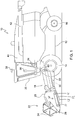
- FIG. 1 shows a side view of a combine 10 in a schematic representation.
- Combine 10 comprises a supporting structure 12 which is supported on driven, front wheels 14 and steerable, rear wheels 16 on the ground and is movable over a field. Instead of the wheels 14, 16, caterpillar drives could also occur.
- An inclined conveyor 18 is attached to the front of the supporting structure 12, on the front of which in turn a belt cutter 22 is removably attached, which comprises a reel 24, a cutter bar 26 and a supporting frame 28.
- the inclined conveyor 18 comprises a conveyor 30 and can be pivoted by an actuator 32 relative to the supporting structure 12 of the combine 10 about a horizontal and transverse to the forward direction axis, which usually coincides with the axis of rotation of the upper deflection roller of the conveyor 30, around the height of the Belt cutter 22 (or any other, instead of the belt cutter 22 attached to the inclined conveyor 18 header) change above the ground to adjust the working height of the belt cutter 22 and the latter at the end of the field (in the headlands).
- the actuator 32 is connected to a control unit 34, which in turn is coupled to an operator interface 36 and a position determination device 38.
- a threshing and separating device and a cleaning device are arranged in the interior of the supporting structure in a manner known per se.
- the cleaned grain is in a grain tank 40 is temporarily stored and can be transferred to a transport vehicle via an unloading conveyor 42.
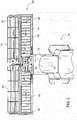
- the belt cutter 22 comprises two outer belt conveyors 44, each of which is connected to a drive 46, which drives them during harvesting operation in such a way that their upper sides move inwards, as shown by the arrows, around the one which is gripped by the reel 24 and by the cutter bar 26 to convey cut crop to the center of the belt cutter 22, where it is taken over by a central belt conveyor 48, which is driven by a drive 50 assigned to it, and is transported backwards into the inclined conveyor 18.
- the central belt conveyor 48 comprises a conveyor belt 58 which rotates around two deflection rollers 54, 56, one of which is coupled to the drive 50. Instead of the front deflection roller 54, the drive 50 could also drive the rear deflection roller 56. Below the lower, returning run of the conveyor belt 58 there is a trough 52, in which crops accumulate during harvesting, of which certain quantities are continuously released to the front by the central belt conveyor 48, but are carried back again by the incoming crop and therefore not get lost. However, these quantities of crop can fall on the field if no or very little crop arrives from the front in the headlands or crop gaps.
- the drives 46 and 50 are connected to the control unit 34, which in harvesting operation according to the flow diagram of FIG Figure 4 is working.
- a query is made as to whether the combine harvester 10 is in a headland mode in which the belt cutter 22 has been moved from a lowered harvesting position to a raised headland position (or has been raised for other reasons, for example to avoid weed pick-up). .
- the position of the combine harvester 10 can be detected on the basis of the signals from the satellite-based position determining device 38 and a map of the field that is stored before the harvesting process or during the harvesting process, or it is recognized from the inputs into the operator interface 36 whether the operator is lifting the band cutting unit 22 via the actuator 32, or the position of the actuator 32 or an element moved by it is detected with a suitable sensor 60, or the control unit 34 receives from an automatic headland management system, which automatically performs a headland sequence on the headland Combine 10 causes a corresponding information. If the belt cutter 22 is not in a headland mode, step 114 follows, in which the drive 50 of the central belt conveyor 48 is switched on.
- the drives 46 of the outer belt conveyors 44, the conveyor 30 of the inclined conveyor 18 and the threshing and separating device and the cleaning device of the combine harvester 10 are also in operation. In the headlands, they can remain switched on or after corresponding (possibly different) times sufficient to process the entire crop (and that which is brought in in step 106) picked up by the belt cutter 22 before the start of headland operation, in the combine 10, switched off or slowed down. Step 114 is followed again by step 102.
- step 104 follows in which a time t1 is waited and during which drive 50 drives belt conveyor 50 at the previous speed, which also applies analogously to drives 46 , which drive the outer belt conveyors 44 at the speed used in the harvesting operation, and for the drive of the inclined conveyor 18.
- This time t1 is chosen such that the entire crop picked up by the belt cutter 22 before the start of headland operation (that on the middle belt conveyor 48 and the outer belt conveyors 44) is discharged into the inclined conveyor 18 by the middle belt conveyor 48 and no freshly picked crop is lying on the belt conveyors 44, 48.
- the control unit 34 causes the drive 50 to reverse, i.e.
- step 106 is carried out in accordance with step 108 for a time t2 which is sufficient to remove the crop from the pan 52.
- control unit 34 instructs the drive 50 in step 106 to merely stop the middle belt conveyor 48. This also prevents the crop that has accumulated under the central belt conveyor 48 from being released to the front. It would also be conceivable to first stop the middle belt conveyor 48 for a certain time in step 106 and only then to reverse it.
- step 110 the drive 50 is stopped and in step 112 it is queried whether the harvesting operation has been started again. If this is the case, step 114 follows again (in which the drives 46, which may be switched off and the inclined conveyor 18 and the threshing and separating and cleaning device of the combine harvester 10 are also switched on again) and otherwise step 110.
Landscapes
- Life Sciences & Earth Sciences (AREA)
- Environmental Sciences (AREA)
- Harvester Elements (AREA)
- Combines (AREA)
Abstract
Description
- Die Erfindung betrifft eine Anordnung zur Steuerung des Betriebs eines Bandschneidwerks eines Mähdreschers, wobei das Bandschneidwerk mit einem mittleren Bandförderer und zwei äußeren Bandförderern ausgestattet und an einem mittels eines Aktors höhensteuerbaren und aushebbaren Schrägförderer des Mähdreschers angebracht ist.
- Bei der Getreideernte werden üblicherweise Schneidwerke verwendet, bei denen das Erntegut durch eine Haspel erfasst und nach hinten gefördert wird, damit es durch einen Messerbalken von den im Boden verbleibenden Wurzeln abgeschnitten werden kann. Der Querfördervorgang des abgeschnittenen Ernteguts erfolgt bei einer Art von Schneidwerken durch eine Querförderschnecke, in deren Mittelbereich Abgabeförderer in Form von gesteuerten Fingern vorgesehen sind, um das Erntegut in den Schrägförderer eines Mähdreschers zu transferieren. Die Querförderschnecke wird bei einer anderen Art von Schneidwerken, die als Bandschneidwerke (engl.: "draper belt header") bezeichnet werden, durch äußere Förderbänder ersetzt, die das abgeschnittene Erntegut oberschlächtig zur Mitte des Schneidwerks fördern, wo es durch ein mittleres Förderband nach hinten zur Abgabeöffnung des Schneidwerks gefördert wird und dort in den Schrägförderer gelangt. Oberhalb der Abgabeöffnung kann eine mit Fingern ausgestattete Fördertrommel angeordnet sein (vgl.
DE 10 2013 206 515 A1 ). - Der mittlere Bandförderer arbeitet ebenfalls oberschlächtig. An seiner Unterseite ist eine Wanne angeordnet, die verhindern soll, dass in den Innenraum des Bandförderers und an seine Unterseite gelangendes Erntegut auf das Feld fällt. In dieser Wanne sammeln sich beim Erntevorgang somit nach und nach Mengen an Erntegut an, die auch beträchtliche Mengen an Korn enthalten. Der mittlere Bandförderer gibt dieses Erntegut im Erntebetrieb kontinuierlich nach vorn ab. Dieses vom mittleren Bandförderer nach vorn abgegebene Erntegut wird, solange noch Erntegut von vorn einläuft, durch das von vorn einlaufende Erntegut mitgenommen und gelangt wieder auf den mittleren Bandförderer und wird schließlich in den Schrägförderer eingezogen. Wird das Schneidwerk am Vorgewende jedoch ausgehoben, entfällt das von vorn einlaufende Material, was dazu führt, dass der mittlere Bandförderer ein Teil des angesammelten Ernteguts nach vorn abgibt und es auf den Erdboden fällt. Dadurch entstehen einerseits unerwünschte Kornverluste, andererseits hat man unerwünschten Kornaufgang am Feldende.
- Ein an sich bekanntes Reversieren aller Bandförderer eines Bandschneidwerks auf eine Bedienereingabe hin (
US 8 186 136 B2 ,US 2018/0104937 A1 ) ist zwar an sich bekannt, für einen Bediener aber umständlich und kann, da kein Weiterbetrieb des Schrägförderers in der normalen Förderrichtung (sondern ebenfalls ein Reversieren) vorgesehen ist, allenfalls dazu führen, dass das unterhalb des mittleren Förderbands angesammelte Material auf das Feld ausgeworfen wird, was das beschriebene Problem nicht löst. - Die
EP 1 419 688 A1 beschreibt ein Maisgebiss zur Ganzpflanzenernte zur Verwendung mit einem Feldhäcksler, das beim Ausheben selbsttätig reversiert wird, um an den auswärts weisenden, zum Abschneiden und Abfördern des Ernteguts dienenden Förder- und Führungselementen eines Endlosförderers hängende Maisblätter abzuwerfen. Hier geht es somit darum, die Schneid- und Förderelemente des Endlosförderers, an denen die Pflanzenteile hängenbleiben, durch Reversieren von den Blättern zu befreien. - In der
EP 1 576 870 A1 wird vorgeschlagen, einen Erntevorsatz und einen Einzugsförderer einer Erntemaschine im Vorgewende selbsttätig gegenüber dem Erntebetrieb langsamer anzutreiben, um Kraftstoff zu sparen. Das Verlangsamen des Einzugsförderers erfolgt gegenüber dem Verlangsamen des Erntevorsatzes zeitverzögert, um das gesamte aufgenommene Material noch mit derselben Geschwindigkeit in die Erntemaschine zu verbringen. Ein Anhalten oder gar Reversieren des Erntevorsatzes ist nicht vorgesehen. - Die
WO 2012/166947 A1 beschreibt eine automatische Entstopfungsprozedur für einen Mähdrescher, bei welcher im Falle eines Reversierens der Erntegutbearbeitungseinheit des Mähdreschers zunächst alle Förderbänder des Bandschneidwerks angehalten werden. Wenn der Reversiervorgang der Erntegutbearbeitungseinheit länger als eine bestimmte Zeit dauert, wird auch der mittlere Bandförderer des Bandschneidwerks reversiert. Nach dem Beenden des Reversierens der Erntegutbearbeitungseinheit wird zunächst der mittlere Bandförderer wieder in der normalen Richtung angetrieben und nach dem Verstreichen einer vorbestimmten Zeit werden schließlich auch die äußeren Bandförderer in Gang gesetzt. Auch diese Vorgehensweise kann das beschriebene Problem nicht lösen. - Die der Erfindung zu Grunde liegende Aufgabe wird darin gesehen, eine gegenüber dem Stand der Technik verbesserte Anordnung zur Steuerung des Betriebs eines Bandschneidwerks bereitzustellen, welche einerseits bedienerfreundlich ist und andererseits die Verluste beim Ausheben vermeidet oder vermindert.
- Die vorliegende Erfindung wird durch die Patentansprüche definiert.
- Eine Anordnung zur Steuerung des Betriebs eines Bandschneidwerks eines Mähdreschers, welches mit einem mittleren Bandförderer und zwei äußeren Bandförderern ausgestattet und an einem mittels eines Aktors höhensteuerbaren und aushebbaren Schrägförderer des Mähdreschers angebracht ist, umfasst eine Steuereinheit, die betreibbar ist, einen Antrieb des mittleren Bandförderers im Falle eines Aushebens des Schrägförderers anzuhalten oder in einen Reversierbetrieb zu verbringen.
- Mit anderen Worten wird vorgeschlagen, ein Anhalten oder ein Reversieren des mittleren Bandförderers automatisch mit dem Ausheben des Schrägförderers zu koppeln. Auf diese Weise vermeidet man die ansonsten auftretenden Erntegutverluste durch das unterhalb des mittleren Bandförderers angesammelte Erntegut beim Ausheben, denn es bleibt nach dem Anhalten an der Unterseite des mittleren Bandförderers oder es wird durch den reversierenden mittleren Bandförderer nach hinten in den Schrägförderer und von diesem in den Mähdrescher verbracht. Ein Eingreifen des Bedieners ist nicht erforderlich.
- Der Aktor des Schrägförderers ist insbesondere betreibbar, den Schrägförderer aus einer Arbeitsposition in eine Vorgewendeposition auszuheben, wobei die Steuereinheit auf das Ausheben in die Vorgewendeposition mit dem Anhalten oder Reversiervorgang des mittleren Bandförderers reagieren kann. Bei einer anderen Ausführungsform erfolgt das Anhalten oder der Reversiervorgang des mittleren Bandförderers bereits auf ein Anheben des Schrägförderers auf eine (unterhalb einer Vorgewendeposition liegenden) Höhe hin, die aber derart hoch liegt, dass davon ausgegangen werden kann, dass kein Erntegut mehr aufgenommen werden soll.
- Die Steuereinheit kann betreibbar sein, den Antrieb abhängig von einem insbesondere manuell eingegebenen Verstellbefehl an den Aktor und/oder abhängig von einer mittels eines Sensors erfassten Position des Schrägförderers und/oder abhängig von einer Ausgabe eines Vorgewendemanagements anzusteuern. Das Vorgewendemanagement kann in an sich bekannter Weise, auf Bedienereingabe oder eine automatische Erkennung der relativen Position des Mähdreschers gegenüber dem Vorgewende, z.B. anhand einer abgespeicherten Karte und eines satellitenbasierten Positionsbestimmungssystems oder mit einer elektrooptischen Einrichtung, die das Vorgewende optisch (z.B. mit einer Kamera oder einem Laserentfernungsmesser erkennt), eine Vorgewendesequenz durchführen, bei der verschiedene Aktoren nacheinander selbsttätig angesteuert werden, um dem Bediener den Wendevorgang im Vorgewende zu erleichtern, ggf. einschließlich der Lenkung des Mähdreschers. Hierzu sei beispielhaft auf die Offenbarung der
EP 1 380 202 A1 verwiesen, die durch Verweis mit in die vorliegenden Unterlagen aufgenommen wird. Das Vorgewendemanagement gibt demnach an einer geeigneten Stelle des Feldes einen Verstellbefehl an den Aktor des Schrägförderers, um letzteren auszuheben, und in zeitlichem oder örtlichem Kontext mit diesem Verstellbefehl eine Anweisung an die Steuereinheit, welche diese veranlasst, den Antrieb des mittleren Bandförderers anzuhalten oder zu reversieren. Das Vorgewendemanagement kann Bestandteil der Steuereinrichtung sein oder umgekehrt. - Die äußeren Bandförderer können mit jeweils einem Antrieb versehen sein, der sie im Erntebetrieb in Richtung auf den mittleren Bandförderer zu in Bewegung versetzt, während der Antrieb des mittleren Bandförderers den mittleren Bandförderer im Erntebetrieb nach hinten in Richtung auf den Schrägförderer zu in Bewegung versetzt.
- Die Steuereinheit kann betreibbar sein, den Antrieb des mittleren Bandförderers auf ein Ausheben des Schrägförderers hin nach einer ersten Zeitverzögerung, die ein Abfördern des sich noch auf den äußeren Bandförderern befindlichen Ernteguts in den Schrägförderer erlaubt, anzuhalten oder zu reversieren und/oder den Antrieb des mittleren Bandförderers anzuweisen, den Reversiervorgang des mittleren Bandförderers nach einer zweiten Zeitverzögerung zu beenden, die ein Abfördern von Erntegut erlaubt, das sich unterhalb des mittleren Bandförderers angesammelt hat.
- Der Schrägförderer kann mit einem Antrieb verbunden sein, der betreibbar ist, nach einem Ausheben für zumindest eine Zeit in förderndem Betrieb zu verbleiben, die ausreicht, von den äußeren Bandförderern herangefördertes Erntegut in den Mähdrescher hinein zu fördern. Ein Abschalten des Schrägförderers im Vorgewende ist zwar denkbar, aber nicht notwendig.
- Die Antriebe der äußeren Bandförderer können mit der Steuereinheit verbunden sein und die Steuereinheit betreibbar sein, die Antriebe der äußeren Bandförderer nach einem Ausheben des Schrägförderers für eine Zeitspanne, die ein Abfördern des auf den äußeren Bandförderern befindlichen Ernteguts auf den mittleren Bandförderer erlaubt, abzuschalten. Bei einer anderen Ausführungsform können die äußeren Bandförderer auch im Vorgewende in ihrem normalen Erntebetrieb bleiben.
- Die Steuereinheit kann betreibbar sein, den Antrieb des mittleren Bandförderers im Falle eines Absenkens des Schrägförderers wieder in einen Erntebetrieb zu versetzen.
- In den Zeichnungen sind zwei nachfolgend näher beschriebene Ausführungsbeispiele der Erfindung dargestellt. Es zeigen:
-
Fig. 1 eine schematische Seitenansicht eines Mähdreschers mit einem am Schrägförderer angebrachten Bandschneidwerk, -
Fig. 2 eine Draufsicht auf den vorderen Bereich des Mähdreschers derFigur 1 und das Bandschneidwerk, -
Fig. 3 einen vertikalen Schnitt durch das Bandschneidwerk entlang der Linie 3-3 derFigur 2 , und -
Fig. 4 ein Flussdiagramm, nach dem die Steuereinheit des Mähdreschers arbeitet. - Die
Figur 1 zeigt eine Seitenansicht eines Mähdreschers 10 in schematischer Darstellung. Der Mähdrescher 10 umfasst eine tragende Struktur 12, die sich auf angetriebenen, vorderen Rädern 14 und lenkbaren, rückwärtigen Rädern 16 auf dem Boden abstützt und über ein Feld bewegbar ist. Anstelle der Räder 14, 16 könnten auch Raupenlaufwerke treten. - An der Vorderseite der tragenden Struktur 12 ist ein Schrägförderer 18 angebracht, an dessen Vorderseite wiederum ein Bandschneidwerk 22 abnehmbar befestigt ist, welches eine Haspel 24, einen Mähbalken 26 und einen tragenden Rahmen 28 umfasst.
- Eine Kabine 20 ist an der tragenden Struktur 12 oberhalb der vorderen Räder 14 angebracht. Der Schrägförderer 18 umfasst einen Förderer 30 und ist durch einen Aktor 32 gegenüber der tragenden Struktur 12 des Mähdreschers 10 um eine horizontal und quer zur Vorwärtsrichtung verlaufende Achse, die üblicherweise mit der Drehachse der oberen Umlenkwalze des Förderers 30 zusammenfällt, schwenkbar, um die Höhe des Bandschneidwerks 22 (oder eines beliebigen anderen, anstelle des Bandschneidwerks 22 am Schrägförderer 18 angebrachten Erntevorsatzes) über dem Boden zur Anpassung der Arbeitshöhe des Bandschneidwerks 22 verändern und letzteres am Feldende (im Vorgewende) ausheben zu können. Dazu ist der Aktor 32 mit einer Steuereinheit 34 verbunden, die ihrerseits mit einer Bedienerschnittstelle 36 und einer Positionsbestimmungseinrichtung 38 gekoppelt ist.
- Im Inneren der tragenden Struktur sind in an sich bekannter Weise eine Dresch- und Trenneinrichtung und eine Reinigungseinrichtung angeordnet. Das gereinigte Korn wird in einem Korntank 40 zwischengespeichert und kann über einen Entladeförderer 42 auf ein Transportfahrzeug überladen werden.
- Es wird nun auf die
Figur 2 verwiesen, in welcher der vordere Bereich des Mähdreschers 10 und das Bandschneidwerk 22 in einer Draufsicht gezeigt werden. Das Bandschneidwerk 22 umfasst zwei äußere Bandförderer 44, die jeweils mit einem Antrieb 46 verbunden sind, der sie im Erntebetrieb derart antreibt, dass ihre Oberseiten sich nach innen bewegen, wie durch die Pfeile gezeigt, um das von der Haspel 24 erfasste und vom Mähbalken 26 abgeschnittene Erntegut zur Mitte des Bandschneidwerks 22 zu fördern, wo es durch einen mittleren Bandförderer 48, der durch einen ihm zugeordneten Antrieb 50 angetrieben wird, übernommen und nach hinten in den Schrägförderer 18 abtransportiert wird. - Anhand der
Figur 3 , die einen vertikalen Schnitt durch den mittleren Bandförderer 48 entlang der Vorwärtsrichtung des Mähdreschers 10. Der mittlere Bandförderer 48 umfasst einen Fördergurt 58, der um zwei Umlenkwalzen 54, 56, von denen eine mit dem Antrieb 50 gekoppelt ist, umläuft. Anstelle der vorderen Umlenkwalze 54 könnte der Antrieb 50 auch die hintere Umlenkwalze 56 antreiben. Unterhalb des unteren, rücklaufenden Trums des Fördergurts 58 ist eine Wanne 52 angeordnet, in welcher sich im Erntebetrieb Erntegut ansammelt, von dem durch den mittleren Bandförderer 48 kontinuierlich gewisse Mengen nach vorn abgegeben, jedoch durch das einlaufende Erntegut wieder nach hinten mitgenommen werden und somit nicht verloren gehen. Diese Mengen an Erntegut können jedoch auf das Feld fallen, wenn im Vorgewende oder Bestandslücken kein oder nur sehr wenig Erntegut von vorn einläuft. - Die (z.B. als Elektro- oder Hydro-Antriebe oder reversierbare und abschaltbare mechanische Antriebe ausgeführten) Antriebe 46 und 50 sind mit der Steuereinheit 34 verbunden, die im Erntebetrieb nach dem Flussdiagramm der
Figur 4 arbeitet. Nach dem Start im Schritt 100 wird abgefragt, ob sich der Mähdrescher 10 in einem Vorgewendemodus befindet, bei dem das Bandschneidwerk 22 aus einer abgesenkten Ernteposition in eine angehobene Vorgewendeposition verbracht wurde (oder aus anderen Gründen angehoben wurde, z.B. um Aufnahme von Unkraut zu vermeiden). Hierzu kann die Position des Mähdreschers 10 anhand der Signale der satellitenbasieren Positionsbestimmungseinrichtung 38 und einer vor dem Erntevorgang oder während des Erntevorgangs abgespeicherten Karte des Felds erfasst werden, oder es wird anhand der Eingaben in die Bedienerschnittstelle 36 erkannt, ob der Bediener ein Ausheben des Bandschneidwerks 22 über den Aktor 32 veranlasst hat, oder es wird die Position des Aktors 32 oder eines von ihm bewegten Elements mit einem geeigneten Sensor 60 detektiert, oder die Steuereinheit 34 erhält von einem selbsttätigen Vorgewendemanagement, das am Vorgewende selbsttätig eine Vorgewendesequenz des Mähdreschers 10 veranlasst, eine entsprechende Information. Falls das Bandschneidwerk 22 nicht in einem Vorgewendemodus ist, folgt der Schritt 114, in dem der Antrieb 50 des mittleren Bandförderers 48 eingeschaltet ist. Beim Erntebetrieb sind auch die Antriebe 46 der äußeren Bandförderer 44, der Förderer 30 des Schrägförderers 18 und die Dresch- und Trenneinrichtung sowie die Reinigungseinrichtung des Mähdreschers 10 im Betrieb. Im Vorgewende können sie eingeschaltet bleiben oder nach entsprechenden (ggf. unterschiedlichen) Zeiten, die dazu hinreichen, das gesamte, vor dem Beginn des Vorgewendebetriebs vom Bandschneidwerk 22 aufgenommene Erntegut (und jenes, das im Schritt 106 herangefördert wird) im Mähdrescher 10 zu verarbeiten, abgeschaltet oder verlangsamt angetrieben werden. Auf den Schritt 114 folgt wieder der Schritt 102. - Falls der Schritt 102 ergeben hat, dass der Mähdrescher 10 im Vorgewendemodus ist, folgt der Schritt 104, in dem eine Zeit t1 abgewartet wird und während welcher der Antrieb 50 den Bandförderer 50 mit der bisherigen Geschwindigkeit antreibt, was analog auch für die Antriebe 46 gilt, welche die äußeren Bandförderer 44 mit der beim Erntebetrieb verwendeten Geschwindigkeit antreiben, und für den Antrieb des Schrägförderers 18. Diese Zeit t1 ist derart gewählt, dass das gesamte, vor dem Beginn des Vorgewendebetriebs vom Bandschneidwerk 22 aufgenommene Erntegut (das auf dem mittleren Bandförderer 48 und den äußeren Bandförderern 44 liegt) durch den mittleren Bandförderer 48 in den Schrägförderer 18 abgegeben wird und kein frisch aufgenommenes Erntegut mehr auf den Bandförderern 44, 48 liegt. Nach dem Schritt 104 veranlasst die Steuereinheit 34 den Antrieb 50, zu reversieren, d.h. die Walze 54 mit gegenüber dem Erntebetrieb gegensinniger Richtung anzutreiben. Dadurch wird das Erntegut, das sich in der Wanne 52 unterhalb des rücklaufenden Trums des Fördergurts 58 angesammelt hat, nach hinten abgefördert und vom weiterhin laufenden Schrägförderer 18 übernommen. Der Reversierbetrieb nach Schritt 106 wird gemäß Schritt 108 für eine Zeit t2 durchgeführt, die ausreicht, das Erntegut aus der Wanne 52 abzufördern.
- Bei einer anderen Ausführungsform wäre es denkbar, dass die Steuereinheit 34 den Antrieb 50 im Schritt 106 anweist, den mittleren Bandförderer 48 lediglich anzuhalten. Auch damit verhindert man, dass das Erntegut, das sich unter dem mittleren Bandförderer 48 angesammelt hat, nach vorn abgegeben wird. Auch wäre es denkbar, den mittleren Bandförderer 48 im Schritt 106 zunächst für eine bestimmte Zeit anzuhalten und erst anschließend zu reversieren.
- Im folgenden Schritt 110 wird der Antrieb 50 gestoppt und im Schritt 112 abgefragt, ob der Erntebetrieb wieder aufgenommen wurde. Ist das der Fall, folgt wieder der Schritt 114 (in dem auch die ggf. abgeschalteten Antriebe 46 und der Schrägförderer 18 und die Dresch- und Trenn- und Reinigungseinrichtung des Mähdreschers 10 wieder eingeschaltet werden) und ansonsten der Schritt 110.
Claims (9)
- Anordnung zur Steuerung des Betriebs eines Bandschneidwerks (22) eines Mähdreschers (10), wobei das Bandschneidwerk (10) mit einem mittleren Bandförderer (48) und zwei äußeren Bandförderern (44) ausgestattet und an einem mittels eines Aktors (32) höhensteuerbaren und aushebbaren Schrägförderer (18) des Mähdreschers (10) angebracht ist, dadurch gekennzeichnet, dass die Anordnung eine Steuereinheit (34) umfasst, die betreibbar ist, einen Antrieb (50) des mittleren Bandförderers (48) im Falle eines Aushebens des Schrägförderers (18) anzuhalten oder in einen Reversierbetrieb zu verbringen.
- Anordnung nach Anspruch 1, wobei der Aktor (32) betreibbar ist, den Schrägförderer (18) aus einer Arbeitsposition in eine Vorgewendeposition auszuheben und die Steuereinheit (34) betreibbar ist, im Falle eines Aushebens des Schrägförderers (18) in eine Vorgewendeposition den Antrieb (50) des mittleren Bandförderers (48) anzuhalten und/oder in einen Reversiermodus zu verbringen.
- Anordnung nach Anspruch 1 oder 2, wobei die Steuereinheit (34) betreibbar ist, den Antrieb (50) abhängig von einem manuell gegebenen Verstellbefehl an den Aktor (32) und/oder abhängig von einer mittels eines Sensors (60) erfassten Position des Schrägförderers (18) und/oder abhängig von einer Ausgabe eines Vorgewendemanagements anzusteuern.
- Anordnung nach einem der vorhergehenden Ansprüche, wobei die äußeren Bandförderer (44) mit jeweils einem Antrieb (46) versehen sind, der sie im Erntebetrieb in Richtung auf den mittleren Bandförderer (48) zu in Bewegung versetzt und der Antrieb (50) des mittleren Bandförderers (48) den mittleren Bandförderer (48) im Erntebetrieb nach hinten in Richtung auf den Schrägförderer (18) zu in Bewegung versetzt.
- Anordnung nach Anspruch 4, wobei die Steuereinheit (34) betreibbar ist, den Antrieb (50) des mittleren Bandförderers (48) auf ein Ausheben des Schrägförderers (18) hin nach einer ersten Zeitverzögerung (t1), die ein Abfördern des auf den äußeren Bandförderern (44) befindlichen Ernteguts in den Schrägförderer (18) erlaubt, anzuhalten oder zu reversieren und/oder den Antrieb (50) des mittleren Bandförderers (48) anzuweisen, den Reversiervorgang des mittleren Bandförderers (48) nach einer zweiten Zeitverzögerung (t2) zu beenden, die ein Abfördern von Erntegut erlaubt, das sich unterhalb des mittleren Bandförderers (48) angesammelt hat.
- Anordnung nach Anspruch 4 oder 5, wobei der Schrägförderer (18) mit einem Antrieb verbunden ist, der betreibbar ist, nach einem Ausheben für zumindest eine Zeit in förderndem Betrieb zu verbleiben, die ausreicht, von den äußeren Bandförderern (44) herangefördertes Erntegut in den Mähdrescher (10) hinein zu fördern.
- Anordnung nach einem der Ansprüche 4 bis 6, wobei die Antriebe (46) der äußeren Bandförderer (44) mit der Steuereinheit (34) verbunden sind und die Steuereinheit (34) betreibbar ist, die Antriebe (46) der äußeren Bandförderer (44) nach einem Ausheben des Schrägförderers (18) für eine Zeitspanne, die ein Abfördern des auf den äußeren Bandförderern (44) befindlichen Ernteguts auf den mittleren Bandförderer (48) erlaubt, abzuschalten.
- Anordnung nach einem der vorhergehenden Ansprüche, wobei die Steuereinheit (34) betreibbar ist, den Antrieb (50) des mittleren Bandförderers (48) im Falle eines Absenkens des Schrägförderers (18) in einen Erntebetrieb zu versetzen.
- Mähdrescher (10) mit einem Bandschneidwerk (22) und einer Anordnung nach einem der vorhergehenden Ansprüche.
Applications Claiming Priority (1)
| Application Number | Priority Date | Filing Date | Title |
|---|---|---|---|
| DE102018218442.9A DE102018218442A1 (de) | 2018-10-29 | 2018-10-29 | Anordnung zur Steuerung des Betriebs eines Bandschneidwerks |
Publications (2)
| Publication Number | Publication Date |
|---|---|
| EP3646701A1 true EP3646701A1 (de) | 2020-05-06 |
| EP3646701B1 EP3646701B1 (de) | 2024-05-29 |
Family
ID=68295976
Family Applications (1)
| Application Number | Title | Priority Date | Filing Date |
|---|---|---|---|
| EP19203866.9A Active EP3646701B1 (de) | 2018-10-29 | 2019-10-17 | Mähdrescher mit einer anordnung zur steuerung des betriebs eines bandschneidwerks |
Country Status (3)
| Country | Link |
|---|---|
| US (1) | US11523561B2 (de) |
| EP (1) | EP3646701B1 (de) |
| DE (1) | DE102018218442A1 (de) |
Families Citing this family (7)
| Publication number | Priority date | Publication date | Assignee | Title |
|---|---|---|---|---|
| US10806079B2 (en) | 2018-02-26 | 2020-10-20 | Deere & Company | Automatic product harvesting method and control system |
| JP6960898B2 (ja) | 2018-10-31 | 2021-11-05 | 株式会社豊田中央研究所 | 電源装置 |
| JP6898904B2 (ja) | 2018-10-31 | 2021-07-07 | 株式会社豊田中央研究所 | 電源装置 |
| BR112022021229A2 (pt) * | 2020-04-24 | 2022-12-06 | Cnh Ind America Llc | Sistema e método para controlar a operação do implemento de colheita de uma colheitadeira agrícola quando uma operação de colheita cessa |
| AR125724A1 (es) * | 2021-04-28 | 2023-08-09 | Cnh Ind America Llc | Sistemas y métodos para controlar la velocidad y sentido de un transportador lateral de un cabezal agrícola |
| US12495741B2 (en) * | 2021-10-28 | 2025-12-16 | Deere & Company | Harvesting machine belt pickup header with movable pickup belt assembly |
| DE102022127703A1 (de) * | 2022-10-20 | 2024-04-25 | Deere & Company | Erntevorsatz zur Ganzpflanzenernte |
Citations (7)
| Publication number | Priority date | Publication date | Assignee | Title |
|---|---|---|---|---|
| EP1380202A1 (de) | 2002-07-11 | 2004-01-14 | Deere & Company | Automatisches Steuersystem eines Mähdreschers |
| EP1419688A1 (de) | 2002-11-15 | 2004-05-19 | Maschinenfabrik Bernard Krone GmbH | Erntegerät zum Ernten von Mais oder dgl. stengelartigem Erntegut |
| EP1576870A1 (de) | 2004-03-18 | 2005-09-21 | Maschinenfabrik Bernard Krone GmbH | Erntemaschine |
| US8186136B2 (en) | 2009-04-03 | 2012-05-29 | Deere & Company | Agricultural harvester with a draper platform direction shuttle |
| WO2012166947A1 (en) | 2011-05-31 | 2012-12-06 | Cnh America Llc | System and method of controlling a draper header during and after a slug clean out operation |
| DE102013206515A1 (de) | 2012-05-04 | 2013-11-07 | Deere & Company | Fördertrommel mit axial beweglichen Fingern |
| US20180104937A1 (en) | 2015-05-05 | 2018-04-19 | 3M Innovative Properties Company | Sound and heat insulating blanket |
Family Cites Families (18)
| Publication number | Priority date | Publication date | Assignee | Title |
|---|---|---|---|---|
| GB2289201A (en) * | 1994-05-07 | 1995-11-15 | Ford New Holland Nv | Drive reversal for agricultural harvester |
| US7191582B2 (en) * | 2005-05-10 | 2007-03-20 | Deere & Company | Header terrain following system |
| US20080276590A1 (en) * | 2006-02-10 | 2008-11-13 | Agco Corporation | Flexible draper and cutter bar with tilt arm for cutterbar drive |
| US20080271426A1 (en) * | 2006-02-10 | 2008-11-06 | Agco Corporation | Draper belt with crop-retaining rib |
| US20090277145A1 (en) * | 2008-05-09 | 2009-11-12 | Agco Corporation | Header height control system with multiple potentiometer input |
| US7886511B2 (en) * | 2008-05-09 | 2011-02-15 | Agco Corporation | Draper head with flexible cutterbar having rigid center section |
| US20090277148A1 (en) * | 2008-05-09 | 2009-11-12 | Agco Corporation | Flexible draper and cutter bar having shiftable crop divider with deflector |
| US20090277144A1 (en) * | 2008-05-09 | 2009-11-12 | Agco Corporation | Spring flotation for center deck of draper header |
| US7921627B2 (en) * | 2008-05-09 | 2011-04-12 | Agco Corporation | Interlocking belt guards for a draper header |
| US8087224B1 (en) * | 2010-09-16 | 2012-01-03 | Deere & Company | Flexible draper platform with pivot geometry |
| US8720170B2 (en) * | 2011-10-18 | 2014-05-13 | Deere & Company | Header height control with tire flex compensation |
| US8973342B2 (en) * | 2013-03-08 | 2015-03-10 | Deere & Company | Load control system and method for an agricultural harvester |
| BE1022840B1 (nl) * | 2015-03-09 | 2016-09-20 | Cnh Industrial Belgium Nv | Maaier voor een oogstmachine die een verplaatsbare maaibalktafel bevat |
| EP3114919B1 (de) * | 2015-07-08 | 2020-10-28 | Zürn Harvesting GmbH & Co. KG | Schneidwerksanordnung |
| DE102016115589A1 (de) * | 2016-08-23 | 2018-03-01 | Claas Selbstfahrende Erntemaschinen Gmbh | Bandschneidwerk |
| US10701862B2 (en) * | 2018-02-01 | 2020-07-07 | Macdon Industries Ltd. | Agricultural header with float control |
| US11516964B2 (en) * | 2019-04-30 | 2022-12-06 | Deere & Company | Position controlled gauge wheels on a harvesting machine header that move with a feeder house move command |
| US11304370B2 (en) * | 2019-10-24 | 2022-04-19 | Cnh Industrial America Llc | Reversible compression auger on harvesting header |
-
2018
- 2018-10-29 DE DE102018218442.9A patent/DE102018218442A1/de not_active Withdrawn
-
2019
- 2019-10-17 EP EP19203866.9A patent/EP3646701B1/de active Active
- 2019-10-28 US US16/665,042 patent/US11523561B2/en active Active
Patent Citations (7)
| Publication number | Priority date | Publication date | Assignee | Title |
|---|---|---|---|---|
| EP1380202A1 (de) | 2002-07-11 | 2004-01-14 | Deere & Company | Automatisches Steuersystem eines Mähdreschers |
| EP1419688A1 (de) | 2002-11-15 | 2004-05-19 | Maschinenfabrik Bernard Krone GmbH | Erntegerät zum Ernten von Mais oder dgl. stengelartigem Erntegut |
| EP1576870A1 (de) | 2004-03-18 | 2005-09-21 | Maschinenfabrik Bernard Krone GmbH | Erntemaschine |
| US8186136B2 (en) | 2009-04-03 | 2012-05-29 | Deere & Company | Agricultural harvester with a draper platform direction shuttle |
| WO2012166947A1 (en) | 2011-05-31 | 2012-12-06 | Cnh America Llc | System and method of controlling a draper header during and after a slug clean out operation |
| DE102013206515A1 (de) | 2012-05-04 | 2013-11-07 | Deere & Company | Fördertrommel mit axial beweglichen Fingern |
| US20180104937A1 (en) | 2015-05-05 | 2018-04-19 | 3M Innovative Properties Company | Sound and heat insulating blanket |
Also Published As
| Publication number | Publication date |
|---|---|
| US20200128745A1 (en) | 2020-04-30 |
| EP3646701B1 (de) | 2024-05-29 |
| DE102018218442A1 (de) | 2020-04-30 |
| US11523561B2 (en) | 2022-12-13 |
Similar Documents
| Publication | Publication Date | Title |
|---|---|---|
| EP3646701B1 (de) | Mähdrescher mit einer anordnung zur steuerung des betriebs eines bandschneidwerks | |
| EP3560314B1 (de) | Schneidwerk mit selbsttätiger einstellung der haspelzinkenorientierung | |
| EP2067399B1 (de) | Anordnung zur Verstellung der Position einer Aufnehmertrommel und eines Niederhalters einer landwirtschaftlichen Erntemaschine | |
| DE102015206845B4 (de) | Schneidwerk zur Ganzpflanzenernte | |
| EP1046333A1 (de) | Erntemaschine | |
| DE102008014001A1 (de) | Landwirtschaftliche Erntemaschine mit einer Überladeeinrichtung | |
| DE10134137A1 (de) | Selbstfahrende landwirtschaftliche Erntemaschine | |
| EP3603379A1 (de) | Anordnung zur selbsttätigen kontrolle des antriebs eines seitlich an einem erntevorsatz angebrachten elements, das zur aufteilung des ernteguts an der grenze zwischen stehen bleibendem und abzuerntenden bestand dient | |
| DE10142978A1 (de) | Erntevorsatz | |
| EP3597027B1 (de) | Mähdrescher mit einem schrägförderer mit aktorisch verstellbarer, unterer umlenkwalze | |
| EP1946632B1 (de) | Maschine zum Mähen von stängelartigem Erntegut | |
| EP2659761A1 (de) | Erntemaschine mit einer Schneidvorrichtung | |
| EP2742794A1 (de) | Landwirtschaftliche Erntemaschine und Verfahren zum Warten einer solchen Erntemaschine | |
| EP1535505A1 (de) | Maschine zum Mähen von stängelartigem Erntegut | |
| EP3984347B1 (de) | Schneidwerk mit seitlichen förderhilfen | |
| EP1464215B1 (de) | Maschine zum Mähen von stängelartigem Erntegut | |
| EP1013159A2 (de) | Steuerung für landwirtschaftliche Arbeitsmaschine | |
| BE1022788B1 (de) | Maschine zum mähen von stängelartigem erntegut mit sukzessive ansteigender querfördergeschwindigkeit | |
| DE102019005662A1 (de) | Auswurfkrümmer für einen Feldhäcksler | |
| EP3967127B1 (de) | Selbstfahrender feldhäcksler | |
| BE1025904B1 (de) | Steueranordnung zur Kontrolle einer an der Unterseite eines stromab einer Häckseltrommel angeordneten Kanals eines Feldhäckslers angeordneten Verschlusseinrichtung | |
| EP1419688B1 (de) | Erntegerät zum Ernten von Mais oder dgl. stengelartigem Erntegut | |
| EP0056873A1 (de) | Vorrichtung zum Aufnehmen von Rüben | |
| DE102005009939A1 (de) | Erntevorsatz für landwirtschaftliche Erntemaschinen | |
| DE102019008801B4 (de) | Einzugsanordnung mit Fangblech und Feldhäcksler mit Einzugsanordnung |
Legal Events
| Date | Code | Title | Description |
|---|---|---|---|
| PUAI | Public reference made under article 153(3) epc to a published international application that has entered the european phase |
Free format text: ORIGINAL CODE: 0009012 |
|
| STAA | Information on the status of an ep patent application or granted ep patent |
Free format text: STATUS: THE APPLICATION HAS BEEN PUBLISHED |
|
| AK | Designated contracting states |
Kind code of ref document: A1 Designated state(s): AL AT BE BG CH CY CZ DE DK EE ES FI FR GB GR HR HU IE IS IT LI LT LU LV MC MK MT NL NO PL PT RO RS SE SI SK SM TR |
|
| AX | Request for extension of the european patent |
Extension state: BA ME |
|
| STAA | Information on the status of an ep patent application or granted ep patent |
Free format text: STATUS: REQUEST FOR EXAMINATION WAS MADE |
|
| 17P | Request for examination filed |
Effective date: 20201106 |
|
| RBV | Designated contracting states (corrected) |
Designated state(s): AL AT BE BG CH CY CZ DE DK EE ES FI FR GB GR HR HU IE IS IT LI LT LU LV MC MK MT NL NO PL PT RO RS SE SI SK SM TR |
|
| STAA | Information on the status of an ep patent application or granted ep patent |
Free format text: STATUS: EXAMINATION IS IN PROGRESS |
|
| 17Q | First examination report despatched |
Effective date: 20220510 |
|
| GRAP | Despatch of communication of intention to grant a patent |
Free format text: ORIGINAL CODE: EPIDOSNIGR1 |
|
| STAA | Information on the status of an ep patent application or granted ep patent |
Free format text: STATUS: GRANT OF PATENT IS INTENDED |
|
| INTG | Intention to grant announced |
Effective date: 20240102 |
|
| GRAS | Grant fee paid |
Free format text: ORIGINAL CODE: EPIDOSNIGR3 |
|
| GRAA | (expected) grant |
Free format text: ORIGINAL CODE: 0009210 |
|
| STAA | Information on the status of an ep patent application or granted ep patent |
Free format text: STATUS: THE PATENT HAS BEEN GRANTED |
|
| AK | Designated contracting states |
Kind code of ref document: B1 Designated state(s): AL AT BE BG CH CY CZ DE DK EE ES FI FR GB GR HR HU IE IS IT LI LT LU LV MC MK MT NL NO PL PT RO RS SE SI SK SM TR |
|
| REG | Reference to a national code |
Ref country code: CH Ref legal event code: EP |
|
| REG | Reference to a national code |
Ref country code: IE Ref legal event code: FG4D Free format text: LANGUAGE OF EP DOCUMENT: GERMAN |
|
| REG | Reference to a national code |
Ref country code: DE Ref legal event code: R096 Ref document number: 502019011358 Country of ref document: DE |
|
| REG | Reference to a national code |
Ref country code: LT Ref legal event code: MG9D |
|
| REG | Reference to a national code |
Ref country code: NL Ref legal event code: MP Effective date: 20240529 |
|
| PG25 | Lapsed in a contracting state [announced via postgrant information from national office to epo] |
Ref country code: IS Free format text: LAPSE BECAUSE OF FAILURE TO SUBMIT A TRANSLATION OF THE DESCRIPTION OR TO PAY THE FEE WITHIN THE PRESCRIBED TIME-LIMIT Effective date: 20240929 |
|
| PG25 | Lapsed in a contracting state [announced via postgrant information from national office to epo] |
Ref country code: BG Free format text: LAPSE BECAUSE OF FAILURE TO SUBMIT A TRANSLATION OF THE DESCRIPTION OR TO PAY THE FEE WITHIN THE PRESCRIBED TIME-LIMIT Effective date: 20240529 |
|
| PG25 | Lapsed in a contracting state [announced via postgrant information from national office to epo] |
Ref country code: HR Free format text: LAPSE BECAUSE OF FAILURE TO SUBMIT A TRANSLATION OF THE DESCRIPTION OR TO PAY THE FEE WITHIN THE PRESCRIBED TIME-LIMIT Effective date: 20240529 Ref country code: FI Free format text: LAPSE BECAUSE OF FAILURE TO SUBMIT A TRANSLATION OF THE DESCRIPTION OR TO PAY THE FEE WITHIN THE PRESCRIBED TIME-LIMIT Effective date: 20240529 |
|
| PG25 | Lapsed in a contracting state [announced via postgrant information from national office to epo] |
Ref country code: GR Free format text: LAPSE BECAUSE OF FAILURE TO SUBMIT A TRANSLATION OF THE DESCRIPTION OR TO PAY THE FEE WITHIN THE PRESCRIBED TIME-LIMIT Effective date: 20240830 |
|
| PG25 | Lapsed in a contracting state [announced via postgrant information from national office to epo] |
Ref country code: ES Free format text: LAPSE BECAUSE OF FAILURE TO SUBMIT A TRANSLATION OF THE DESCRIPTION OR TO PAY THE FEE WITHIN THE PRESCRIBED TIME-LIMIT Effective date: 20240529 |
|
| PG25 | Lapsed in a contracting state [announced via postgrant information from national office to epo] |
Ref country code: PL Free format text: LAPSE BECAUSE OF FAILURE TO SUBMIT A TRANSLATION OF THE DESCRIPTION OR TO PAY THE FEE WITHIN THE PRESCRIBED TIME-LIMIT Effective date: 20240529 |
|
| PG25 | Lapsed in a contracting state [announced via postgrant information from national office to epo] |
Ref country code: LV Free format text: LAPSE BECAUSE OF FAILURE TO SUBMIT A TRANSLATION OF THE DESCRIPTION OR TO PAY THE FEE WITHIN THE PRESCRIBED TIME-LIMIT Effective date: 20240529 |
|
| PG25 | Lapsed in a contracting state [announced via postgrant information from national office to epo] |
Ref country code: PL Free format text: LAPSE BECAUSE OF FAILURE TO SUBMIT A TRANSLATION OF THE DESCRIPTION OR TO PAY THE FEE WITHIN THE PRESCRIBED TIME-LIMIT Effective date: 20240529 Ref country code: NO Free format text: LAPSE BECAUSE OF FAILURE TO SUBMIT A TRANSLATION OF THE DESCRIPTION OR TO PAY THE FEE WITHIN THE PRESCRIBED TIME-LIMIT Effective date: 20240829 Ref country code: LV Free format text: LAPSE BECAUSE OF FAILURE TO SUBMIT A TRANSLATION OF THE DESCRIPTION OR TO PAY THE FEE WITHIN THE PRESCRIBED TIME-LIMIT Effective date: 20240529 Ref country code: IS Free format text: LAPSE BECAUSE OF FAILURE TO SUBMIT A TRANSLATION OF THE DESCRIPTION OR TO PAY THE FEE WITHIN THE PRESCRIBED TIME-LIMIT Effective date: 20240929 Ref country code: HR Free format text: LAPSE BECAUSE OF FAILURE TO SUBMIT A TRANSLATION OF THE DESCRIPTION OR TO PAY THE FEE WITHIN THE PRESCRIBED TIME-LIMIT Effective date: 20240529 Ref country code: GR Free format text: LAPSE BECAUSE OF FAILURE TO SUBMIT A TRANSLATION OF THE DESCRIPTION OR TO PAY THE FEE WITHIN THE PRESCRIBED TIME-LIMIT Effective date: 20240830 Ref country code: FI Free format text: LAPSE BECAUSE OF FAILURE TO SUBMIT A TRANSLATION OF THE DESCRIPTION OR TO PAY THE FEE WITHIN THE PRESCRIBED TIME-LIMIT Effective date: 20240529 Ref country code: ES Free format text: LAPSE BECAUSE OF FAILURE TO SUBMIT A TRANSLATION OF THE DESCRIPTION OR TO PAY THE FEE WITHIN THE PRESCRIBED TIME-LIMIT Effective date: 20240529 Ref country code: BG Free format text: LAPSE BECAUSE OF FAILURE TO SUBMIT A TRANSLATION OF THE DESCRIPTION OR TO PAY THE FEE WITHIN THE PRESCRIBED TIME-LIMIT Effective date: 20240529 Ref country code: RS Free format text: LAPSE BECAUSE OF FAILURE TO SUBMIT A TRANSLATION OF THE DESCRIPTION OR TO PAY THE FEE WITHIN THE PRESCRIBED TIME-LIMIT Effective date: 20240829 |
|
| PG25 | Lapsed in a contracting state [announced via postgrant information from national office to epo] |
Ref country code: NL Free format text: LAPSE BECAUSE OF FAILURE TO SUBMIT A TRANSLATION OF THE DESCRIPTION OR TO PAY THE FEE WITHIN THE PRESCRIBED TIME-LIMIT Effective date: 20240529 |
|
| PG25 | Lapsed in a contracting state [announced via postgrant information from national office to epo] |
Ref country code: NL Free format text: LAPSE BECAUSE OF FAILURE TO SUBMIT A TRANSLATION OF THE DESCRIPTION OR TO PAY THE FEE WITHIN THE PRESCRIBED TIME-LIMIT Effective date: 20240529 |
|
| PG25 | Lapsed in a contracting state [announced via postgrant information from national office to epo] |
Ref country code: DK Free format text: LAPSE BECAUSE OF FAILURE TO SUBMIT A TRANSLATION OF THE DESCRIPTION OR TO PAY THE FEE WITHIN THE PRESCRIBED TIME-LIMIT Effective date: 20240529 |
|
| PG25 | Lapsed in a contracting state [announced via postgrant information from national office to epo] |
Ref country code: EE Free format text: LAPSE BECAUSE OF FAILURE TO SUBMIT A TRANSLATION OF THE DESCRIPTION OR TO PAY THE FEE WITHIN THE PRESCRIBED TIME-LIMIT Effective date: 20240529 |
|
| PG25 | Lapsed in a contracting state [announced via postgrant information from national office to epo] |
Ref country code: CZ Free format text: LAPSE BECAUSE OF FAILURE TO SUBMIT A TRANSLATION OF THE DESCRIPTION OR TO PAY THE FEE WITHIN THE PRESCRIBED TIME-LIMIT Effective date: 20240529 |
|
| PG25 | Lapsed in a contracting state [announced via postgrant information from national office to epo] |
Ref country code: SK Free format text: LAPSE BECAUSE OF FAILURE TO SUBMIT A TRANSLATION OF THE DESCRIPTION OR TO PAY THE FEE WITHIN THE PRESCRIBED TIME-LIMIT Effective date: 20240529 Ref country code: RO Free format text: LAPSE BECAUSE OF FAILURE TO SUBMIT A TRANSLATION OF THE DESCRIPTION OR TO PAY THE FEE WITHIN THE PRESCRIBED TIME-LIMIT Effective date: 20240529 |
|
| PG25 | Lapsed in a contracting state [announced via postgrant information from national office to epo] |
Ref country code: SM Free format text: LAPSE BECAUSE OF FAILURE TO SUBMIT A TRANSLATION OF THE DESCRIPTION OR TO PAY THE FEE WITHIN THE PRESCRIBED TIME-LIMIT Effective date: 20240529 |
|
| PG25 | Lapsed in a contracting state [announced via postgrant information from national office to epo] |
Ref country code: SM Free format text: LAPSE BECAUSE OF FAILURE TO SUBMIT A TRANSLATION OF THE DESCRIPTION OR TO PAY THE FEE WITHIN THE PRESCRIBED TIME-LIMIT Effective date: 20240529 Ref country code: SK Free format text: LAPSE BECAUSE OF FAILURE TO SUBMIT A TRANSLATION OF THE DESCRIPTION OR TO PAY THE FEE WITHIN THE PRESCRIBED TIME-LIMIT Effective date: 20240529 Ref country code: RO Free format text: LAPSE BECAUSE OF FAILURE TO SUBMIT A TRANSLATION OF THE DESCRIPTION OR TO PAY THE FEE WITHIN THE PRESCRIBED TIME-LIMIT Effective date: 20240529 Ref country code: EE Free format text: LAPSE BECAUSE OF FAILURE TO SUBMIT A TRANSLATION OF THE DESCRIPTION OR TO PAY THE FEE WITHIN THE PRESCRIBED TIME-LIMIT Effective date: 20240529 Ref country code: DK Free format text: LAPSE BECAUSE OF FAILURE TO SUBMIT A TRANSLATION OF THE DESCRIPTION OR TO PAY THE FEE WITHIN THE PRESCRIBED TIME-LIMIT Effective date: 20240529 Ref country code: CZ Free format text: LAPSE BECAUSE OF FAILURE TO SUBMIT A TRANSLATION OF THE DESCRIPTION OR TO PAY THE FEE WITHIN THE PRESCRIBED TIME-LIMIT Effective date: 20240529 |
|
| PG25 | Lapsed in a contracting state [announced via postgrant information from national office to epo] |
Ref country code: IT Free format text: LAPSE BECAUSE OF FAILURE TO SUBMIT A TRANSLATION OF THE DESCRIPTION OR TO PAY THE FEE WITHIN THE PRESCRIBED TIME-LIMIT Effective date: 20240529 |
|
| REG | Reference to a national code |
Ref country code: DE Ref legal event code: R097 Ref document number: 502019011358 Country of ref document: DE |
|
| PLBE | No opposition filed within time limit |
Free format text: ORIGINAL CODE: 0009261 |
|
| STAA | Information on the status of an ep patent application or granted ep patent |
Free format text: STATUS: NO OPPOSITION FILED WITHIN TIME LIMIT |
|
| PG25 | Lapsed in a contracting state [announced via postgrant information from national office to epo] |
Ref country code: SI Free format text: LAPSE BECAUSE OF FAILURE TO SUBMIT A TRANSLATION OF THE DESCRIPTION OR TO PAY THE FEE WITHIN THE PRESCRIBED TIME-LIMIT Effective date: 20240529 |
|
| 26N | No opposition filed |
Effective date: 20250303 |
|
| REG | Reference to a national code |
Ref country code: CH Ref legal event code: PL |
|
| GBPC | Gb: european patent ceased through non-payment of renewal fee |
Effective date: 20241017 |
|
| PG25 | Lapsed in a contracting state [announced via postgrant information from national office to epo] |
Ref country code: MC Free format text: LAPSE BECAUSE OF FAILURE TO SUBMIT A TRANSLATION OF THE DESCRIPTION OR TO PAY THE FEE WITHIN THE PRESCRIBED TIME-LIMIT Effective date: 20240529 |
|
| PG25 | Lapsed in a contracting state [announced via postgrant information from national office to epo] |
Ref country code: GB Free format text: LAPSE BECAUSE OF NON-PAYMENT OF DUE FEES Effective date: 20241017 |
|
| PG25 | Lapsed in a contracting state [announced via postgrant information from national office to epo] |
Ref country code: LU Free format text: LAPSE BECAUSE OF NON-PAYMENT OF DUE FEES Effective date: 20241017 Ref country code: BE Free format text: LAPSE BECAUSE OF NON-PAYMENT OF DUE FEES Effective date: 20241031 |
|
| PG25 | Lapsed in a contracting state [announced via postgrant information from national office to epo] |
Ref country code: FR Free format text: LAPSE BECAUSE OF NON-PAYMENT OF DUE FEES Effective date: 20241031 |
|
| PG25 | Lapsed in a contracting state [announced via postgrant information from national office to epo] |
Ref country code: CH Free format text: LAPSE BECAUSE OF NON-PAYMENT OF DUE FEES Effective date: 20241031 |
|
| REG | Reference to a national code |
Ref country code: BE Ref legal event code: MM Effective date: 20241031 |
|
| PG25 | Lapsed in a contracting state [announced via postgrant information from national office to epo] |
Ref country code: SE Free format text: LAPSE BECAUSE OF FAILURE TO SUBMIT A TRANSLATION OF THE DESCRIPTION OR TO PAY THE FEE WITHIN THE PRESCRIBED TIME-LIMIT Effective date: 20240529 |
|
| PG25 | Lapsed in a contracting state [announced via postgrant information from national office to epo] |
Ref country code: IE Free format text: LAPSE BECAUSE OF NON-PAYMENT OF DUE FEES Effective date: 20241017 |
|
| REG | Reference to a national code |
Ref country code: AT Ref legal event code: MM01 Ref document number: 1689819 Country of ref document: AT Kind code of ref document: T Effective date: 20241017 |
|
| PGFP | Annual fee paid to national office [announced via postgrant information from national office to epo] |
Ref country code: DE Payment date: 20250919 Year of fee payment: 7 |
|
| PG25 | Lapsed in a contracting state [announced via postgrant information from national office to epo] |
Ref country code: AT Free format text: LAPSE BECAUSE OF NON-PAYMENT OF DUE FEES Effective date: 20241017 |
|
| PG25 | Lapsed in a contracting state [announced via postgrant information from national office to epo] |
Ref country code: PT Free format text: LAPSE BECAUSE OF NON-PAYMENT OF DUE FEES Effective date: 20240529 |
|
| PG25 | Lapsed in a contracting state [announced via postgrant information from national office to epo] |
Ref country code: CY Free format text: LAPSE BECAUSE OF FAILURE TO SUBMIT A TRANSLATION OF THE DESCRIPTION OR TO PAY THE FEE WITHIN THE PRESCRIBED TIME-LIMIT; INVALID AB INITIO Effective date: 20191017 |
|
| PG25 | Lapsed in a contracting state [announced via postgrant information from national office to epo] |
Ref country code: HU Free format text: LAPSE BECAUSE OF FAILURE TO SUBMIT A TRANSLATION OF THE DESCRIPTION OR TO PAY THE FEE WITHIN THE PRESCRIBED TIME-LIMIT; INVALID AB INITIO Effective date: 20191017 |