EP3646416B1 - Cable processing apparatus - Google Patents
Cable processing apparatus Download PDFInfo
- Publication number
- EP3646416B1 EP3646416B1 EP17742381.1A EP17742381A EP3646416B1 EP 3646416 B1 EP3646416 B1 EP 3646416B1 EP 17742381 A EP17742381 A EP 17742381A EP 3646416 B1 EP3646416 B1 EP 3646416B1
- Authority
- EP
- European Patent Office
- Prior art keywords
- carriage
- crimping
- horizontal
- cassette
- processing apparatus
- Prior art date
- Legal status (The legal status is an assumption and is not a legal conclusion. Google has not performed a legal analysis and makes no representation as to the accuracy of the status listed.)
- Active
Links
Images





Classifications
-
- H—ELECTRICITY
- H01—ELECTRIC ELEMENTS
- H01R—ELECTRICALLY-CONDUCTIVE CONNECTIONS; STRUCTURAL ASSOCIATIONS OF A PLURALITY OF MUTUALLY-INSULATED ELECTRICAL CONNECTING ELEMENTS; COUPLING DEVICES; CURRENT COLLECTORS
- H01R43/00—Apparatus or processes specially adapted for manufacturing, assembling, maintaining, or repairing of line connectors or current collectors or for joining electric conductors
- H01R43/04—Apparatus or processes specially adapted for manufacturing, assembling, maintaining, or repairing of line connectors or current collectors or for joining electric conductors for forming connections by deformation, e.g. crimping tool
- H01R43/048—Crimping apparatus or processes
- H01R43/055—Crimping apparatus or processes with contact member feeding mechanism
-
- H—ELECTRICITY
- H01—ELECTRIC ELEMENTS
- H01R—ELECTRICALLY-CONDUCTIVE CONNECTIONS; STRUCTURAL ASSOCIATIONS OF A PLURALITY OF MUTUALLY-INSULATED ELECTRICAL CONNECTING ELEMENTS; COUPLING DEVICES; CURRENT COLLECTORS
- H01R43/00—Apparatus or processes specially adapted for manufacturing, assembling, maintaining, or repairing of line connectors or current collectors or for joining electric conductors
- H01R43/04—Apparatus or processes specially adapted for manufacturing, assembling, maintaining, or repairing of line connectors or current collectors or for joining electric conductors for forming connections by deformation, e.g. crimping tool
- H01R43/048—Crimping apparatus or processes
-
- Y—GENERAL TAGGING OF NEW TECHNOLOGICAL DEVELOPMENTS; GENERAL TAGGING OF CROSS-SECTIONAL TECHNOLOGIES SPANNING OVER SEVERAL SECTIONS OF THE IPC; TECHNICAL SUBJECTS COVERED BY FORMER USPC CROSS-REFERENCE ART COLLECTIONS [XRACs] AND DIGESTS
- Y10—TECHNICAL SUBJECTS COVERED BY FORMER USPC
- Y10T—TECHNICAL SUBJECTS COVERED BY FORMER US CLASSIFICATION
- Y10T29/00—Metal working
- Y10T29/53—Means to assemble or disassemble
- Y10T29/5313—Means to assemble electrical device
- Y10T29/532—Conductor
- Y10T29/53209—Terminal or connector
- Y10T29/53213—Assembled to wire-type conductor
- Y10T29/53235—Means to fasten by deformation
-
- Y—GENERAL TAGGING OF NEW TECHNOLOGICAL DEVELOPMENTS; GENERAL TAGGING OF CROSS-SECTIONAL TECHNOLOGIES SPANNING OVER SEVERAL SECTIONS OF THE IPC; TECHNICAL SUBJECTS COVERED BY FORMER USPC CROSS-REFERENCE ART COLLECTIONS [XRACs] AND DIGESTS
- Y10—TECHNICAL SUBJECTS COVERED BY FORMER USPC
- Y10T—TECHNICAL SUBJECTS COVERED BY FORMER US CLASSIFICATION
- Y10T29/00—Metal working
- Y10T29/53—Means to assemble or disassemble
- Y10T29/5313—Means to assemble electrical device
- Y10T29/53261—Means to align and advance work part
Definitions
- the present disclosure relates to a cable processing apparatus having a crimping device.
- the crimping device is loaded with an exchangeable crimping cassette.
- a crimp cassette comprises e. g. a crimping tool or parts of a crimping tool, as well as a magazine (a reel) of crimp contacts or the like.
- EP 1 381 123 A1 discloses a crimping press in which a cassette having a reel of contacts can be inserted by hand.
- WO 2006/136930 A1 discloses a crimping machine having a crimping station, the crimping station comprising a crimping tool, a tool holder, a drive unit, a contact feed and a contact store. An integrated tool unit (a reel) can be pushed into the tool holder at the crimping station. The integrated tool units can be fed and removed by means of a swivel mechanism to and from a storage rack.
- the crimping aggregate comprises a tool that is mounted on the aggregate, for crimping a contact element with a cable element.
- a plurality of rolls and a feeding device form a single common unit.
- JP 2004 111264 A describes a terminal crimping device having single horizontal guide and a single vertical guide extending separate from one another.
- WO 2006/136930 A1 describes a crimping apparatus having a lower clamping device for holding and orientation of an integrated tool unit.
- the integrated tool unit comprises a crimping tool, a contact strip guide, a contact strip unwinder 7 and a paper strip winder.
- a cable processing apparatus having a crimping device loaded with an exchangeable crimping cassette.
- the cable processing apparatus comprises a crimping cassette exchanging device.
- the crimping cassette exchanging device comprises a plurality of carriages, each carriage having a crimping cassette holding device adapted to attach to and to detach from a crimping cassette; a horizontal carriage guide for providing a substantially horizontal guided movement of the carriages; a vertical carriage guide for providing a substantially vertical guided movement of a carriage from an initial vertical position to the crimping device or vice-versa, wherein the vertical carriage guide is arranged relative to the horizontal carriage guide such that one of the plurality of carriages is vertically movable at a time; a carriage shifting device adapted to controllably perform the horizontal guided movement; and a carriage lifting device adapted to controllably perform the vertical guided movement.
- the vertical movement is a movement substantially in the vertical direction relative to the cable processing apparatus in its operational position
- the horizontal movement is a movement substantially in a plane which is orthogonal to the vertical direction.
- a guided movement is a movement which is restricted or forced, by suitable guiding means, into the desired direction.
- suitable guiding means is a guiding rail.
- the horizontal carriage guide provides a substantially horizontal guided movement of the carriages.
- the horizontal guided movement may be a rectilinear or a curved movement; yet, it is substantially performed in a plane which is orthogonal to the vertical direction.
- the horizontal guided movement is performed substantially on the same vertical level.
- This level may be substantially a ground level of the crimping cassettes attached to the carriages.
- a ground level includes both a level in which the crimping cassettes have a contact with the ground, e. g. by means of a suitable roller, or a level in which the crimping cassettes are slightly lifted, e. g. by a few centimeters, but still in the vicinity of the ground.
- one carriage at a time may be brought into a horizontal position from which it is moveable along the vertical carriage guide.
- This carriage is referred to as a vertically moveable carriage.
- the initial vertical position of the vertically moveable carriage may be a position in which the respective carriage is on a vertical level which corresponds to the vertical level of the horizontal guided movement.
- the vertically moveable carriage which can be moved along the vertical carriage guide out of the initial vertical position to a vertical position, or vertical level, in which a cassette loading or unloading operation of a crimping cassette to or from the crimping device is possible.
- the vertically moveable carriage may be horizontally moved again, along the horizontal carriage guide, out of the position in which a vertical guided movement of this carriage can be performed. Then, for example, another carriage of the plurality of carriages may be moved along the horizontal carriage guide to become the vertically moveable carriage.
- the horizontal guided movement is controllably performed by a carriage shifting device, such as, without limitation, a linear drive or a controllable pneumatic cylinder.
- a carriage shifting device such as, without limitation, a linear drive or a controllable pneumatic cylinder.
- the vertical guided movement is controllably performed by a carriage lifting device, such as, without limitation, a linear drive or a controllable pneumatic cylinder, typically a rodless cylinder.
- each of the different carriages may have attached thereto a crimping cassette with suitable crimping contacts according to the needs for the cable processing operation to be performed.
- the crimping cassette releaseably attacheable to the carriage may be loaded to or unloaded from the crimping device.
- the crimping cassette exchanging device is directly attached to, or fixed on, the cable processing apparatus.
- Multiple carriages can be attached, or provided, directly at the apparatus. Some or each of the carriages may have assigned a specific crimping cassette.
- the crimping cassettes can be readily selected and exchanged, without the need of additional storing racks for the cassettes. Furthermore, no complicated and fault-prone swiveling mechanism is needed.
- the cable processing apparatus as disclosed herein allows an easy, reliable and space-efficient way of automatically changing the crimping cassette.
- the cable processing apparatus further comprises a control device adapted to control the horizontal guided movement according to a carriage selection signal. Additionally or alternatively, the control device is adapted to control the vertical guided movement according to a carriage selection signal.
- the carriage selection signal is indicative of one specific carriage out of the plurality of carriages which is to be driven to the crimping device.
- the carriage selection signal may be indicative of a particular crimping cassette or a particular type of crimping cassette, provided the corresponding carriage which holds the respective crimping cassette is known.
- the carriage selection signal may be generated by the cable processing device itself or by a higher level control, and it may be supplied to the control device.
- the carriage selection signal is generated according to the need of the cable processing apparatus at a particular point in time, such as a type of crimp contacts to be processed and/or a type of crimping tool to use in the cable processing operation.
- the control device may be configured such that it controls the carriage shifting device and/or the carriage lifting device according to the carriage selection signal.
- a control device may thus provide a way to automatically select and load a particular crimping cassette or a particular type of crimping cassette to the crimping device.
- the carriages each comprising a coupling mechanism having mutually matching counterparts to couple to neighboring ones when each of the respective neighboring carriages is in its respective initial vertical position, wherein the coupling mechanism is designed such that the counterparts are detached from one another when any one of the neighboring carriages is lifted from its respective initial vertical position.
- the horizontal carriage guide comprises at least a first horizontal guiderail and at least a second horizontal guiderail arranged such that a horizontal gap is provided in between the horizontal guiderails in the horizontal direction, the vertical carriage guide being arranged such that it extends, at least partially, through the horizontal gap.
- the gap width of the horizontal gap substantially corresponds to a total width of a carriage in the horizontal direction.
- the crimping cassette holding device comprises a clamping holder for attaching to the crimping cassette.
- a clamping holder By means of a clamping holder, an attaching or detaching operation of the crimping cassette can be easily and reliably performed.
- An easy attaching or detaching operation of the crimping cassette is particularly desirable in an automatic crimping cassette exchanging operation at the crimping device.
- the crimping cassette can easily be replaced by a different one when it is lowered, i. e. in its initial vertical position.
- the crimping cassette holding device is adapted to lift the crimping cassette for attaching it to the clamping holder.
- the carriage shifting device is operated pneumatically. Additionally or alternatively, the carriage lifting device is operated pneumatically.
- a pneumatic operation comprises e. g. a pneumatic device being operated, such as, without limitation, a double-acting pneumatic cylinder forcing a piston into the desired direction.
- the desired direction may be any one of the upward direction and the downward direction of substantially vertical movement in the case of the carriage lifting device, and it may be any one of the left-right substantially horizontal direction in the case of the carriage shifting device.
- the pneumatic cylinder is a rodless pneumatic cylinder.
- a pneumatic operation includes a suitable electric driving or triggering of the respective device which is operated pneumatically, e. g. by means of a control device or the like.
- the carriage shifting device is operated electrically. Additionally or alternatively, the carriage lifting device is operated electrically.
- An electrical operation comprises e. g. a linear drive being operated, such as, without limitation, a linear motor.
- the carriage shifting device when the carriage shifting device is operated pneumatically, the carriage lifting device may also be operated pneumatically, or the carriage lifting device may be operated electrically.
- the carriage shifting device when the carriage lifting device is operated pneumatically, the carriage shifting device may also be operated pneumatically, or the carriage shifting device may be operated electrically.
- the carriage shifting device when the carriage shifting device is operated electrically, the carriage lifting device may also be operated electrically, or the carriage lifting device may be operated pneumatically.
- the carriage shifting device when the carriage lifting device is operated electrically, the carriage shifting device may also be operated electrically, or the carriage shifting device may be operated pneumatically.
- each carriage comprises an arresting device for releaseably arresting at least one carriage with the carriage lifting device.
- the arresting device may be a locking cylinder or locking bolt which can be controllably extended and retracted into a mating part of the carriage lifting device when the respective carriage is in its initial vertical position.
- the crimping device comprises a locking device for releaseably locking a loaded crimping cassette.
- a locking device may help ensure that a crimping cassette is reliably locked in an operational position on the crimping device for performing a crimp operation.
- the locking device comprises a centering unit for centering the loaded crimping cassette.
- a centering hole is provided on the locking device as a centering unit or as part of a centering unit.
- the centering unit such as the centering hole, is adapted to mate with a corresponding centering counterpart provided on the crimping cassette.
- the centering counterpart is a centering bolt.
- the centering hole is provided on the crimping cassette, and the centering bolt as the respective counterpart is provided on the locking device.
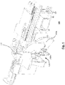
- Fig. 1 is a perspective view of a cable processing apparatus 100 according to an embodiment of the present disclosure.
- Fig. 1 provides an overview of the parts to be described in the following in more detail.
- the cable processing apparatus 100 has a crimping device 110 attached to it.
- the crimping device 110 comprises e. g. a crimping press, and it is loadable with exchangeable crimping cassettes 200a, 200b, each crimping cassette 200a, 200b comprising a reel of crimping elements, such as crimping contacts.
- a crimping cassette 200a, 200b For loading a crimping cassette 200a, 200b to the crimping device 110, it has to be taken into a proper position with respect to the crimping device 110 and attached in an operable or working manner to the crimping device 110, i. e. lifted to the crimping device 110.
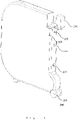
- Fig. 2 illustrates, in a perspective view, an exemplary crimping cassette 200 to be used with a cable processing apparatus 100 of an embodiment.
- Each of the crimping cassettes 200a, 200b may be configured as a general crimping cassette 200 of Fig. 2 .
- the crimping cassette 200 comprises a roller 204 for rolling it to and from a proper position of the cable processing apparatus 100 as described in more detail below.
- a crimping tool 210 may be attached to the crimping cassette 200. In a loading operation to the crimping device, the crimping tool 210 is inserted into the crimping press of the crimping device 110.
- the crimping cassette 200 comprises an indentation 203 on each of its sides (one of them not shown in the perspective view of Fig. 2 ) for mating with corresponding parts of a clamping bracket, which is described in more detail below. Furthermore, the crimping cassette 200 comprises a centering bolt 202 for centering the cassette 200 in a proper position in the crimping device 110. Here, centering may refer to a general alignment procedure of the cassette 200 to achieve a proper alignment or arrangement. Moreover, the crimping cassette 200 is provided with an upper holding bolt 206 and a lower holding bolt 207 for clamping the cassette to a corresponding clamping holder, as described in more detail below.
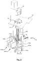
- Fig. 3 shows, in a perspective view, a crimping cassette exchanging device 120 in relation with the crimping device 110.
- the crimping cassette exchanging device 120 is located below a supporting table 115 of the crimping device 110.
- the crimping device 110 comprises the crimping press, and a locking device 111 for releasably locking a loaded crimping cassette.
- the locking device 111 comprises a centering hole 112 for mating with a corresponding centering counterpart on the crimping cassette.
- the crimping cassette exchanging device 120 comprises a pair of first horizontal guiderails 156a, 156b and a pair (not shown in Fig. 3 ) of second horizontal guiderails 157a, 157b arranged such that a horizontal gap 158 (see Fig. 5 ) is present in between the pair of first horizontal guiderails 156a, 156b and the pair of second horizontal guiderails 157a, 157b.
- the horizontal guiderails 156a, 156b, 157a, 157b constitute a horizontal carriage guide. Substantially in the same vertical plane, and crossing the horizontal gap 158, there is a vertical carriage guide 165.
- a carriage 130a and a carriage 130b are each provided with a pair of casters or rollers.
- the carriages 130a, 130b can be moved in the horizontal direction along the horizontal carriage guide.
- both the carriage 130a and the carriage 130b are at a vertical level substantially corresponding to a ground level of a crimp cassette to be attached.
- Each of the carriages 130a, 130b is provided with a crimping cassette holding device 140a, 140b for attaching to a crimp cassette.
- the crimping cassette holding devices 140a, 140b each comprise a shifting plate 143a, 143b for establishing a clamping operation, as described below in more detail.
- a carriage shifting device 150 in the embodiment of Fig. 3 comprises a pneumatic drive, such as a double-action pneumatic cylinder, which can be controlled to move, or shift, the carriages 130a, 130b in the horizontal direction along the horizontal carriage guide.
- a carriage lifting device 160 in the embodiment of Fig. 3 comprises a pneumatic drive, such as a rodless pneumatic cylinder, which can be controlled to move, or shift, the carriages 130a, 130b in the vertical direction along the vertical carriage guide 165.
- the carriage shifting device 150 and the carriage lifting device 160 may comprise drives other than pneumatic drives, e. g. linear electric drives.
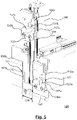
- Fig. 4 is a perspective view showing the crimping cassette exchanging device 120 of Fig. 3 .
- the crimping cassette holding devices 140a, 140b are not shown for convenience.
- Each of the carriages 130a, 130b comprises an arresting device 131a, 131b, which can be controlled to mate with a corresponding counterpart, e. g. an opening, provided on the carriage lifting device 160.
- counterparts such as openings 121, 122 for the arresting devices 131a, 131b can also be provided on fixed parts of the crimping cassette exchanging device 120.
- the carriages 130a, 130b which are not lifted at a specific point in time when another carriage has been lifted, such as the carriage 130a of Fig. 5 to be discussed below, can be locked into its position by the arresting device 131a being inserted into the opening 121, which can be helpful to prevent an undesirable horizontal movement of the carriage 130a in question.
- the carriages which remain in an unlifted position at a certain point in time can be blocked or locked in place, and the carriage which is lifted and finally brought back to its initial vertical position can be coupled to the unlifted carriages in a reliable manner.
- the carriage 130b has been brought, or shifted, into a position in which it can be moved, by means of the carriage lifting device 160, towards the crimping device.
- This position is an initial vertical position, and from this position, the carriage 130b is vertically moveable.
- a catch device 132 is provided to transmit the horizontal movement of the double-action pneumatic cylinder of the carriage shifting device 150 to the carriage 130b.
- the catch device 132 is configured with a gripping section which is bifurcated in the downward direction. The two arms of the gripping section are configured to engage with a part of the plunger of the pneumatic cylinder. When the carriage 130b is lifted by the carriage lifting device 160, the two arms of the gripping section disengage from the plunger, such that the upward movement of the carriage 130b is not adversely affected by the catch device 132.
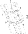
- Fig. 5 is a perspective view corresponding to Fig. 4 , where the carriage 130b has been lifted, or vertically moved, out of its initial vertical position.
- the carriage 130b as each of the plurality of carriages, is provided with intermediate elements 156c, 157c of the first horizontal guiderail and the second horizontal guiderail, respectively.
- the carriages 130a, 130b can be guided, or shifted, in rolling engagement via the intermediate elements 156c, 157c.
- the entire chain of more than two carriages 130a, 130b can be moved, in the horizontal direction, along the paths composed of the first horizontal guiderails 156a, 156b with the intermediate element 156c arranged in the horizontal gap 158 between the guiderails 156a, 156b, and the second horizontal guiderails 157a, 157b with the intermediate element 157c arranged in the horizontal gap 158 between the guiderails 157a, 157b.
- the horizontal gap 158 is bridged by the intermediate elements 156c, 157c.
- the intermediate elements 156c, 157c are configured and arranged such that the upward and downward movement of the carriage 130a, 130b to be lifted or lowered is not negatively affected, e. g. by providing a sufficient space between the horizontal ends of the intermediate elements 156c, 157c and their respective opposite horizontal ends of the horizontal guiderails 156a, 156b and 157a, 157b.
- each of the carriages 130a, 130b comprises a first part 136a, 136b of a coupling mechanism and a second part-137b of a coupling mechanism.
- the first parts 136a, 136b are designed such that they mate with a neighboring second part 137b to transmit a movement in the horizontal direction from one carriage 130a to a neighboring carriage 130b.
- the first parts 136a, 136b and the second parts 137b form corresponding counterparts of the coupling mechanism.
- a horizontal chain of carriages can be established having a desired length, such as a chain of two, three, four or even more carriages.
- some or each of the carriages of the chain may have a crimping cassette 200 attached thereto, wherein the crimping cassettes 200 may each comprise a different crimping tool 210, a different crimping contact, or both.
- the respective second parts 137b are designed as coupling bolts which mate with a suitable matching profile of the respective first parts 136a, 136b.
- the first parts 136a, 136b detach from their corresponding second parts 137b, allowing an unhindered movement in the horizontal direction.
- Fig. 7 shows a variant of Fig. 5 , where the carriage lifting device has been moved, while having lifted a carriage, towards the crimping device (not shown in Fig. 7 ) on a carriage lifting device guiderail 161. This may help to facilitate the handling of a crimping cassette to be loaded to or unloaded from the crimping device 110.
- Fig. 8 illustrates, in a sectional side view, parts of the crimping cassette exchanging device 120 and parts of the crimping cassette 200 according to an embodiment.
- the shifting plate 143b of the crimping cassette holding device 140b is an unlock position.
- the unlock position the upper clamping holder 141b and the lower clamping holder 142b of the shifting plate 143b are released with respect to the upper holding bolt 206 and the lower holding bolt 207 of the crimping cassette 200, respectively.
- the crimping cassette 200 has ground contact and is removable from the crimping cassette holding device 140b, for example in order to refill the crimping contacts, to replace it by another crimping cassette 200 and the like.
- the shifting plate 143b is selectably moveable vertically into a clamping position, which is shown in Fig. 9 .
- the upper clamping holder 141b engages the upper holding bolt 206
- the lower clamping holder 142 engages the lower holding bolt 207. Selecting the unlock position and the clamping position may be performed manually by a switch, or automatically, e. g. by means of a sensor device or the like.
- the crimping cassette 200 In the clamping position, the crimping cassette 200 is slightly lifted, such that - while still being close to the ground - it is freely moveable in the horizontal direction together with the movement of the carriage 130b which it is attached to.
- the shifting plate 143b is shaped such that both the upper holding bolt 206 and the lower holding bolt 207 are aligned in the sideways direction.
- Fig. 10 shows, in a perspective illustration, a detailed view of the locking device 111. Further to the centering hole 112, the locking device 111 is provided with brackets 113 on each of the sides of the locking device.
- Figs. 11 and 12 show, each in a sectional top view, the locking device 111 and parts of a cassette 200 relative to the locking device 111.
- the brackets are in an open position, allowing the cassette 200 to be moved to and from the locking device.
- a centering bolt provided on the crimping cassette (not shown) mates with the centering hole 112 (not shown in Figs. 11 and 12 ) of the locking device 111, such that the cassette 200 is centered and aligned.
- the brackets 113 are closed, and each bracket 113 engages with one of the indentations 203 provided laterally on the cassette 200. Thereby, the brackets 113 push the cassette 200 towards the locking device 111 and have it tightly fixed thereon.
- the locking device 111 is guided, in the horizontal direction, by means of guiding rods (not shown) and can be moved away from the crimping press, e. g. by a pneumatic cylinder.
- the brackets 113 are brought into the open or unlocked position, e. g. by torsion springs.
- the cassette 200 may be moved to or from the locking device, e. g. by the horizontal movement of the carriage lifting device 160 on the carriage lifting device guiderail 161.
- the force limit of the device which performs the movement of the locking device 111 is higher than the force limit of the device which performs the horizontal movement of the carriage lifting device 160.
- the locking device 111 then serves as a mechanical stop for this horizontal movement.
- the carriage lifting device 160 continues its movement, and the cassette 200 is brought into its final position. Then, parts of the brackets 113 come into contact with a control surface of the press of the crimping device 110, such that the brackets 113 are closed.
Landscapes
- Engineering & Computer Science (AREA)
- Manufacturing & Machinery (AREA)
- Manufacturing Of Electrical Connectors (AREA)
Description
- The present disclosure relates to a cable processing apparatus having a crimping device. The crimping device is loaded with an exchangeable crimping cassette.
- Cable processing apparatuses comprising a crimping device loaded with crimp cassettes are known in the art. A crimp cassette comprises e. g. a crimping tool or parts of a crimping tool, as well as a magazine (a reel) of crimp contacts or the like.
EP 1 381 123 A1 discloses a crimping press in which a cassette having a reel of contacts can be inserted by hand.WO 2006/136930 A1 discloses a crimping machine having a crimping station, the crimping station comprising a crimping tool, a tool holder, a drive unit, a contact feed and a contact store. An integrated tool unit (a reel) can be pushed into the tool holder at the crimping station. The integrated tool units can be fed and removed by means of a swivel mechanism to and from a storage rack. -
DE 20 2011 107870 U1 describes a variable feeding device for a crimping aggregate. The crimping aggregate comprises a tool that is mounted on the aggregate, for crimping a contact element with a cable element. A plurality of rolls and a feeding device form a single common unit. -
JP 2004 111264 A -
WO 2006/136930 A1 describes a crimping apparatus having a lower clamping device for holding and orientation of an integrated tool unit. The integrated tool unit comprises a crimping tool, a contact strip guide, a contact strip unwinder 7 and a paper strip winder. - It is an object of the present disclosure to provide a cable processing apparatus having a crimping device which exhibits a reliable and space-efficient way for a cassette change.
- In view of the above, a cable processing apparatus according to claim 1 is provided. Further aspects, advantages, and features of the present disclosure are apparent from the dependent claims.
- According to one aspect of the disclosure, a cable processing apparatus having a crimping device loaded with an exchangeable crimping cassette is provided. The cable processing apparatus comprises a crimping cassette exchanging device. The crimping cassette exchanging device comprises a plurality of carriages, each carriage having a crimping cassette holding device adapted to attach to and to detach from a crimping cassette; a horizontal carriage guide for providing a substantially horizontal guided movement of the carriages; a vertical carriage guide for providing a substantially vertical guided movement of a carriage from an initial vertical position to the crimping device or vice-versa, wherein the vertical carriage guide is arranged relative to the horizontal carriage guide such that one of the plurality of carriages is vertically movable at a time; a carriage shifting device adapted to controllably perform the horizontal guided movement; and a carriage lifting device adapted to controllably perform the vertical guided movement.
- Throughout this disclosure, it is assumed that the cable processing apparatus is in an operational position in which a cable processing operation can be performed. Thus, as used herein, the vertical movement is a movement substantially in the vertical direction relative to the cable processing apparatus in its operational position, and the horizontal movement is a movement substantially in a plane which is orthogonal to the vertical direction.
- A guided movement, as used herein, is a movement which is restricted or forced, by suitable guiding means, into the desired direction. A non-limiting example for a guiding means is a guiding rail.
- The horizontal carriage guide provides a substantially horizontal guided movement of the carriages. The horizontal guided movement may be a rectilinear or a curved movement; yet, it is substantially performed in a plane which is orthogonal to the vertical direction. The horizontal guided movement is performed substantially on the same vertical level. This level may be substantially a ground level of the crimping cassettes attached to the carriages. A ground level includes both a level in which the crimping cassettes have a contact with the ground, e. g. by means of a suitable roller, or a level in which the crimping cassettes are slightly lifted, e. g. by a few centimeters, but still in the vicinity of the ground.
- By the horizontal guided movement, one carriage at a time may be brought into a horizontal position from which it is moveable along the vertical carriage guide. This carriage is referred to as a vertically moveable carriage.
- The initial vertical position of the vertically moveable carriage may be a position in which the respective carriage is on a vertical level which corresponds to the vertical level of the horizontal guided movement. The vertically moveable carriage which can be moved along the vertical carriage guide out of the initial vertical position to a vertical position, or vertical level, in which a cassette loading or unloading operation of a crimping cassette to or from the crimping device is possible.
- After having been moved back to the initial vertical position, the vertically moveable carriage may be horizontally moved again, along the horizontal carriage guide, out of the position in which a vertical guided movement of this carriage can be performed. Then, for example, another carriage of the plurality of carriages may be moved along the horizontal carriage guide to become the vertically moveable carriage.
- The horizontal guided movement is controllably performed by a carriage shifting device, such as, without limitation, a linear drive or a controllable pneumatic cylinder. Likewise, the vertical guided movement is controllably performed by a carriage lifting device, such as, without limitation, a linear drive or a controllable pneumatic cylinder, typically a rodless cylinder.
- Thus, different carriages may be moved to and from the crimping device. Each of the different carriages may have attached thereto a crimping cassette with suitable crimping contacts according to the needs for the cable processing operation to be performed. In the position at the crimping device, the crimping cassette releaseably attacheable to the carriage may be loaded to or unloaded from the crimping device.
- In some embodiments, the crimping cassette exchanging device is directly attached to, or fixed on, the cable processing apparatus. Multiple carriages can be attached, or provided, directly at the apparatus. Some or each of the carriages may have assigned a specific crimping cassette. Thus, the crimping cassettes can be readily selected and exchanged, without the need of additional storing racks for the cassettes. Furthermore, no complicated and fault-prone swiveling mechanism is needed.
- In this way, the cable processing apparatus as disclosed herein allows an easy, reliable and space-efficient way of automatically changing the crimping cassette.
- According to a further aspect of the disclosure, the cable processing apparatus further comprises a control device adapted to control the horizontal guided movement according to a carriage selection signal. Additionally or alternatively, the control device is adapted to control the vertical guided movement according to a carriage selection signal.
- The carriage selection signal is indicative of one specific carriage out of the plurality of carriages which is to be driven to the crimping device. As such, the carriage selection signal may be indicative of a particular crimping cassette or a particular type of crimping cassette, provided the corresponding carriage which holds the respective crimping cassette is known. The carriage selection signal may be generated by the cable processing device itself or by a higher level control, and it may be supplied to the control device. Typically, the carriage selection signal is generated according to the need of the cable processing apparatus at a particular point in time, such as a type of crimp contacts to be processed and/or a type of crimping tool to use in the cable processing operation.
- The control device may be configured such that it controls the carriage shifting device and/or the carriage lifting device according to the carriage selection signal. A control device may thus provide a way to automatically select and load a particular crimping cassette or a particular type of crimping cassette to the crimping device.
- According to a further aspect of the disclosure, the carriages each comprising a coupling mechanism having mutually matching counterparts to couple to neighboring ones when each of the respective neighboring carriages is in its respective initial vertical position, wherein the coupling mechanism is designed such that the counterparts are detached from one another when any one of the neighboring carriages is lifted from its respective initial vertical position.
- In this way, when shifting the plurality of carriages (when performing the guided horizontal movement), all carriages of the plurality of carriages are moved together which allows for both a push and a pull operation which each acts on any one of the coupled carriages. The counterparts detach from one another without any further action just by lifting a carriage from its initial vertical position. Likewise, a detached carriage attaches, with its respective counterparts, to the plurality of carriages again when it is lowered again into its initial vertical position, e. g. after a cassette has been unloaded from the crimping device and the carriage lifting device has brought the carriage with the cassette to its initial vertical position again.
- According to a further aspect of the disclosure, wherein the horizontal carriage guide comprises at least a first horizontal guiderail and at least a second horizontal guiderail arranged such that a horizontal gap is provided in between the horizontal guiderails in the horizontal direction, the vertical carriage guide being arranged such that it extends, at least partially, through the horizontal gap. This allows for a particularly space-efficient and convenient solution. In particular, carriages with attached crimping cassettes substantially on the ground level may be present on both sides of the vertical carriage guide, and the carriages may be freely selected.
- In some embodiments, the gap width of the horizontal gap substantially corresponds to a total width of a carriage in the horizontal direction. Thus, an unaffected or unhindered vertical guided movement of a vertically moveable carriage is performed.
- According to a further aspect of the disclosure, the crimping cassette holding device comprises a clamping holder for attaching to the crimping cassette. By means of a clamping holder, an attaching or detaching operation of the crimping cassette can be easily and reliably performed. An easy attaching or detaching operation of the crimping cassette is particularly desirable in an automatic crimping cassette exchanging operation at the crimping device. Furthermore, the crimping cassette can easily be replaced by a different one when it is lowered, i. e. in its initial vertical position. In some embodiments, the crimping cassette holding device is adapted to lift the crimping cassette for attaching it to the clamping holder.
- According to a further aspect of the disclosure, the carriage shifting device is operated pneumatically. Additionally or alternatively, the carriage lifting device is operated pneumatically. A pneumatic operation comprises e. g. a pneumatic device being operated, such as, without limitation, a double-acting pneumatic cylinder forcing a piston into the desired direction. The desired direction may be any one of the upward direction and the downward direction of substantially vertical movement in the case of the carriage lifting device, and it may be any one of the left-right substantially horizontal direction in the case of the carriage shifting device. In some embodiments, the pneumatic cylinder is a rodless pneumatic cylinder.
- A pneumatic operation, as used in this context, includes a suitable electric driving or triggering of the respective device which is operated pneumatically, e. g. by means of a control device or the like.
- According to a further aspect of the disclosure, the carriage shifting device is operated electrically. Additionally or alternatively, the carriage lifting device is operated electrically. An electrical operation comprises e. g. a linear drive being operated, such as, without limitation, a linear motor.
- It is to be understood that the above features concerning a pneumatic operation or an electrical operation can be reasonably combined among the carriage shifting device and the carriage lifting device. For example, when the carriage shifting device is operated pneumatically, the carriage lifting device may also be operated pneumatically, or the carriage lifting device may be operated electrically. For example, when the carriage lifting device is operated pneumatically, the carriage shifting device may also be operated pneumatically, or the carriage shifting device may be operated electrically. For example, when the carriage shifting device is operated electrically, the carriage lifting device may also be operated electrically, or the carriage lifting device may be operated pneumatically. For example, when the carriage lifting device is operated electrically, the carriage shifting device may also be operated electrically, or the carriage shifting device may be operated pneumatically.
- According to a further aspect of the disclosure, each carriage comprises an arresting device for releaseably arresting at least one carriage with the carriage lifting device. By way of example and not by limitation, the arresting device may be a locking cylinder or locking bolt which can be controllably extended and retracted into a mating part of the carriage lifting device when the respective carriage is in its initial vertical position.
- According to a further aspect of the disclosure, the crimping device comprises a locking device for releaseably locking a loaded crimping cassette. A locking device may help ensure that a crimping cassette is reliably locked in an operational position on the crimping device for performing a crimp operation.
- In some embodiments, the locking device comprises a centering unit for centering the loaded crimping cassette. In some embodiments, a centering hole is provided on the locking device as a centering unit or as part of a centering unit. In some embodiments, the centering unit, such as the centering hole, is adapted to mate with a corresponding centering counterpart provided on the crimping cassette. In some embodiments, the centering counterpart is a centering bolt. In some embodiments, the centering hole is provided on the crimping cassette, and the centering bolt as the respective counterpart is provided on the locking device.
- The subject matter of the disclosure will be explained in more detail with reference to preferred exemplary embodiments which are illustrated in the accompanying drawings. In the drawings, like reference numerals are assigned to like or corresponding parts.
- In the drawings:
- Fig. 1
- is a perspective view of a cable processing apparatus according to an embodiment of the present disclosure;
- Fig. 2
- is a perspective view of an exemplary crimping cassette useable in connection with the cable processing apparatus of
Fig. 1 ; - Fig. 3
- is a perspective detailed view of parts of the cable processing apparatus of
Fig. 1 ; - Fig. 4
- is a perspective detailed view of parts of the cable processing apparatus of
Fig. 1 ; - Fig. 5
- is a perspective detailed view of parts of the cable processing apparatus of
Fig. 1 ; - Fig. 6
- is a perspective detailed view of parts of the cable processing apparatus of
Fig. 1 ; - Fig. 7
- is a perspective detailed view of parts of the cable processing apparatus of
Fig. 1 ; - Fig. 8
- is a sectional side view of parts of the cable processing apparatus of
Fig. 1 and parts of the crimping cassette ofFig. 2 ; - Fig. 9
- is a sectional side view of parts of the cable processing apparatus of
Fig. 1 and parts of the crimping cassette ofFig. 2 ; - Fig. 10
- is a perspective detailed view of parts of the cable processing apparatus of
Fig. 1 ; - Fig. 11
- is a sectional top view of parts of the cable processing apparatus of
Fig. 1 and parts of the crimping cassette ofFig. 2 ; and - Fig. 12
- is a sectional top view of parts of the cable processing apparatus of
Fig. 1 and parts of the crimping cassette ofFig. 2 . -
Fig. 1 is a perspective view of acable processing apparatus 100 according to an embodiment of the present disclosure.Fig. 1 provides an overview of the parts to be described in the following in more detail. InFig. 1 , thecable processing apparatus 100 has a crimpingdevice 110 attached to it. The crimpingdevice 110 comprises e. g. a crimping press, and it is loadable with exchangeable crimpingcassettes cassette cassette device 110, it has to be taken into a proper position with respect to the crimpingdevice 110 and attached in an operable or working manner to the crimpingdevice 110, i. e. lifted to the crimpingdevice 110. -
Fig. 2 illustrates, in a perspective view, an exemplary crimpingcassette 200 to be used with acable processing apparatus 100 of an embodiment. Each of the crimpingcassettes cassette 200 ofFig. 2 . The crimpingcassette 200 comprises aroller 204 for rolling it to and from a proper position of thecable processing apparatus 100 as described in more detail below. - A crimping
tool 210 may be attached to the crimpingcassette 200. In a loading operation to the crimping device, the crimpingtool 210 is inserted into the crimping press of the crimpingdevice 110. - The crimping
cassette 200 comprises anindentation 203 on each of its sides (one of them not shown in the perspective view ofFig. 2 ) for mating with corresponding parts of a clamping bracket, which is described in more detail below. Furthermore, the crimpingcassette 200 comprises a centeringbolt 202 for centering thecassette 200 in a proper position in the crimpingdevice 110. Here, centering may refer to a general alignment procedure of thecassette 200 to achieve a proper alignment or arrangement. Moreover, the crimpingcassette 200 is provided with anupper holding bolt 206 and alower holding bolt 207 for clamping the cassette to a corresponding clamping holder, as described in more detail below. -
Fig. 3 shows, in a perspective view, a crimpingcassette exchanging device 120 in relation with the crimpingdevice 110. The crimpingcassette exchanging device 120 is located below a supporting table 115 of the crimpingdevice 110. - The crimping
device 110 comprises the crimping press, and alocking device 111 for releasably locking a loaded crimping cassette. Thelocking device 111 comprises a centeringhole 112 for mating with a corresponding centering counterpart on the crimping cassette. - The crimping
cassette exchanging device 120 comprises a pair of firsthorizontal guiderails Fig. 3 ) of secondhorizontal guiderails Fig. 5 ) is present in between the pair of firsthorizontal guiderails horizontal guiderails horizontal guiderails horizontal gap 158, there is avertical carriage guide 165. - A
carriage 130a and acarriage 130b (partially hidden inFig. 3 and better recognizable inFig 4 ) are each provided with a pair of casters or rollers. Thecarriages Fig. 3 , both thecarriage 130a and thecarriage 130b are at a vertical level substantially corresponding to a ground level of a crimp cassette to be attached. - Each of the
carriages cassette holding device cassette holding devices plate - A
carriage shifting device 150 in the embodiment ofFig. 3 comprises a pneumatic drive, such as a double-action pneumatic cylinder, which can be controlled to move, or shift, thecarriages carriage lifting device 160 in the embodiment ofFig. 3 comprises a pneumatic drive, such as a rodless pneumatic cylinder, which can be controlled to move, or shift, thecarriages vertical carriage guide 165. These are examples, and one or both of thecarriage shifting device 150 and thecarriage lifting device 160 may comprise drives other than pneumatic drives, e. g. linear electric drives. -
Fig. 4 is a perspective view showing the crimpingcassette exchanging device 120 ofFig. 3 . InFig. 4 , the crimpingcassette holding devices carriages device carriage lifting device 160. - In addition, counterparts such as
openings devices cassette exchanging device 120. Thecarriages carriage 130a ofFig. 5 to be discussed below, can be locked into its position by the arrestingdevice 131a being inserted into theopening 121, which can be helpful to prevent an undesirable horizontal movement of thecarriage 130a in question. Thus, the carriages which remain in an unlifted position at a certain point in time can be blocked or locked in place, and the carriage which is lifted and finally brought back to its initial vertical position can be coupled to the unlifted carriages in a reliable manner. - In
Fig. 4 , thecarriage 130b has been brought, or shifted, into a position in which it can be moved, by means of thecarriage lifting device 160, towards the crimping device. This position is an initial vertical position, and from this position, thecarriage 130b is vertically moveable. Acatch device 132 is provided to transmit the horizontal movement of the double-action pneumatic cylinder of thecarriage shifting device 150 to thecarriage 130b. As an example, thecatch device 132 is configured with a gripping section which is bifurcated in the downward direction. The two arms of the gripping section are configured to engage with a part of the plunger of the pneumatic cylinder. When thecarriage 130b is lifted by thecarriage lifting device 160, the two arms of the gripping section disengage from the plunger, such that the upward movement of thecarriage 130b is not adversely affected by thecatch device 132. -
Fig. 5 is a perspective view corresponding toFig. 4 , where thecarriage 130b has been lifted, or vertically moved, out of its initial vertical position. As can be seen inFig. 5 , thecarriage 130b, as each of the plurality of carriages, is provided withintermediate elements - In the initial vertical position, e. g. of
Figs. 3 and4 , thecarriages intermediate elements carriages carriage lifting device 160 has brought allcarriages carriages horizontal guiderails intermediate element 156c arranged in thehorizontal gap 158 between theguiderails horizontal guiderails intermediate element 157c arranged in thehorizontal gap 158 between theguiderails horizontal gap 158 is bridged by theintermediate elements intermediate elements carriage intermediate elements horizontal guiderails - As shown in more detail in the perspective partial view of
Fig. 6 , each of thecarriages first part first parts second part 137b to transmit a movement in the horizontal direction from onecarriage 130a to a neighboringcarriage 130b. In other words: Thefirst parts second parts 137b form corresponding counterparts of the coupling mechanism. - In this way, a horizontal chain of carriages can be established having a desired length, such as a chain of two, three, four or even more carriages. Initially, some or each of the carriages of the chain may have a crimping
cassette 200 attached thereto, wherein the crimpingcassettes 200 may each comprise a different crimpingtool 210, a different crimping contact, or both. - In
Fig. 6 , as an example, the respectivesecond parts 137b are designed as coupling bolts which mate with a suitable matching profile of the respectivefirst parts first parts second parts 137b, allowing an unhindered movement in the horizontal direction. -
Fig. 7 shows a variant ofFig. 5 , where the carriage lifting device has been moved, while having lifted a carriage, towards the crimping device (not shown inFig. 7 ) on a carriagelifting device guiderail 161. This may help to facilitate the handling of a crimping cassette to be loaded to or unloaded from the crimpingdevice 110. -
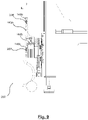
Fig. 8 illustrates, in a sectional side view, parts of the crimpingcassette exchanging device 120 and parts of the crimpingcassette 200 according to an embodiment. - In
Fig. 8 , the shiftingplate 143b of the crimpingcassette holding device 140b is an unlock position. In the unlock position, theupper clamping holder 141b and thelower clamping holder 142b of the shiftingplate 143b are released with respect to theupper holding bolt 206 and thelower holding bolt 207 of the crimpingcassette 200, respectively. In this position, the crimpingcassette 200 has ground contact and is removable from the crimpingcassette holding device 140b, for example in order to refill the crimping contacts, to replace it by another crimpingcassette 200 and the like. - By means of a
clamping cylinder 144b, e. g. a pneumatic cylinder, the shiftingplate 143b is selectably moveable vertically into a clamping position, which is shown inFig. 9 . Here, theupper clamping holder 141b engages theupper holding bolt 206, and the lower clamping holder 142 engages thelower holding bolt 207. Selecting the unlock position and the clamping position may be performed manually by a switch, or automatically, e. g. by means of a sensor device or the like. - In the clamping position, the crimping
cassette 200 is slightly lifted, such that - while still being close to the ground - it is freely moveable in the horizontal direction together with the movement of thecarriage 130b which it is attached to. The shiftingplate 143b is shaped such that both theupper holding bolt 206 and thelower holding bolt 207 are aligned in the sideways direction. -
Fig. 10 shows, in a perspective illustration, a detailed view of thelocking device 111. Further to the centeringhole 112, thelocking device 111 is provided withbrackets 113 on each of the sides of the locking device. -
Figs. 11 and 12 show, each in a sectional top view, thelocking device 111 and parts of acassette 200 relative to thelocking device 111. InFig. 11 , the brackets are in an open position, allowing thecassette 200 to be moved to and from the locking device. A centering bolt provided on the crimping cassette (not shown) mates with the centering hole 112 (not shown inFigs. 11 and 12 ) of thelocking device 111, such that thecassette 200 is centered and aligned. InFig. 12 , thebrackets 113 are closed, and eachbracket 113 engages with one of theindentations 203 provided laterally on thecassette 200. Thereby, thebrackets 113 push thecassette 200 towards the lockingdevice 111 and have it tightly fixed thereon. - The
locking device 111 is guided, in the horizontal direction, by means of guiding rods (not shown) and can be moved away from the crimping press, e. g. by a pneumatic cylinder. In this state, thebrackets 113 are brought into the open or unlocked position, e. g. by torsion springs. In this open state, thecassette 200 may be moved to or from the locking device, e. g. by the horizontal movement of thecarriage lifting device 160 on the carriagelifting device guiderail 161. - For example, the force limit of the device which performs the movement of the
locking device 111 is higher than the force limit of the device which performs the horizontal movement of thecarriage lifting device 160. Thelocking device 111 then serves as a mechanical stop for this horizontal movement. In a subsequent retraction movement of thelocking device 111, thecarriage lifting device 160 continues its movement, and thecassette 200 is brought into its final position. Then, parts of thebrackets 113 come into contact with a control surface of the press of the crimpingdevice 110, such that thebrackets 113 are closed. - Although the invention has been described on the basis of some preferred embodiments, those skilled in the art should appreciate that the present invention is defined by the accompanied claims.
Claims (11)
- Cable processing apparatus (100) having a crimping device (110) loaded with an exchangeable crimping cassette (200, 200a, 200b), the cable processing apparatus (100) comprising a crimping cassette exchanging device (120), wherein the crimping cassette exchanging device (120) comprises:a plurality of carriages (130a, 130b), each carriage (130a, 130b) having a crimping cassette holding device (140a, 140b) adapted to attach to and to detach from a crimping cassette (200, 200a, 200b);a horizontal carriage guide for providing a substantially horizontal guided movement of the carriages (130a, 130b);a vertical carriage guide (165) for providing a substantially vertical guided movement of a carriage (130a, 130b) from an initial vertical position to the crimping device (110) or vice-versa, wherein the vertical carriage guide (165) is arranged relative to the horizontal carriage guide such that one of the plurality of carriages (130a, 130b) is vertically movable at a time;a carriage shifting device (150) adapted to controllably perform the horizontal guided movement;a carriage lifting device (160) adapted to controllably perform the vertical guided movement;a control device adapted to control the horizontal guided movement and/or the vertical guided movement according to a carriage selection signal;characterized in thatthe cassette has a crimping tool attached thereto.
- Cable processing apparatus (100) according to claim 1, the carriages (130a, 130b) each comprising a coupling mechanism (136a, 136b, 137b) having mutually matching counterparts to couple to neighboring ones when each of the respective neighboring carriages (130a, 130b) is in its respective initial vertical position, wherein the coupling mechanism (136a, 136b, 137b) is designed such that the counterparts are detached from one another when any one of the neighboring carriages (130a, 130b) is lifted from its respective initial vertical position.
- Cable processing apparatus (100) according to claim 2, wherein the horizontal carriage guide comprises at least one first horizontal guiderail (156a, 156b) and at least one second horizontal guiderail (157a, 157b) arranged such that a horizontal gap (158) is provided in between the horizontal guiderails (156a, 157a, 156b, 157b) in the horizontal direction, the vertical carriage guide (165) being arranged such that it extends, at least partially, through the horizontal gap.
- Cable processing apparatus (100) according to claim 3, wherein the gap width of the horizontal gap substantially corresponds to a total width of a carriage (130a, 130b) in the horizontal direction.
- Cable processing apparatus (100) according to any one of the preceding claims, wherein the crimping cassette holding device (140a, 140b) comprises at least one clamping holder (141a, 141b, 142a, 142b) for attaching to the crimping cassette (200, 200a, 200b).
- Cable processing apparatus (100) according to claim 5, wherein the clamping holder (141a, 141b, 142a, 142b) is adapted to lift the crimping cassette (200, 200a, 200b) for establishing the attachment.
- Cable processing apparatus (100) according to any one of the preceding claims, wherein the carriage shifting device (150) and/or the carriage lifting device (160) is operated pneumatically.
- Cable processing apparatus (100) according to any one of the preceding claims, wherein the carriage shifting device (150) and/or the carriage lifting device (160) is operated electrically.
- Cable processing apparatus (100) according to any one of the preceding claims, wherein each carriage (130a, 130b) comprises an arresting device (131a, 131b) for releaseably arresting at least one carriage (130a, 130b) with the carriage lifting device (160).
- Cable processing apparatus (100) according to any one of the preceding claims, wherein the crimping device (110) comprises a locking device (111) for releaseably locking the loaded crimping cassette (200, 200a, 200b).
- Cable processing apparatus (100) according to claim 10, wherein the locking device (111) comprises a centering unit for centering the loaded crimping cassette, typically a centering hole (112) for mating with a corresponding centering bolt (202) of the crimping cassette (200, 200a, 200b).
Priority Applications (1)
| Application Number | Priority Date | Filing Date | Title |
|---|---|---|---|
| RS20220622A RS63353B1 (en) | 2017-06-30 | 2017-06-30 | Cable processing apparatus |
Applications Claiming Priority (1)
| Application Number | Priority Date | Filing Date | Title |
|---|---|---|---|
| PCT/EP2017/066343 WO2019001742A1 (en) | 2017-06-30 | 2017-06-30 | Cable processing apparatus |
Publications (2)
| Publication Number | Publication Date |
|---|---|
| EP3646416A1 EP3646416A1 (en) | 2020-05-06 |
| EP3646416B1 true EP3646416B1 (en) | 2022-04-06 |
Family
ID=59383537
Family Applications (1)
| Application Number | Title | Priority Date | Filing Date |
|---|---|---|---|
| EP17742381.1A Active EP3646416B1 (en) | 2017-06-30 | 2017-06-30 | Cable processing apparatus |
Country Status (8)
| Country | Link |
|---|---|
| US (1) | US11139627B2 (en) |
| EP (1) | EP3646416B1 (en) |
| JP (1) | JP6914376B2 (en) |
| CN (1) | CN110945725B (en) |
| MA (1) | MA49491B1 (en) |
| MX (1) | MX2019015444A (en) |
| RS (1) | RS63353B1 (en) |
| WO (1) | WO2019001742A1 (en) |
Families Citing this family (1)
| Publication number | Priority date | Publication date | Assignee | Title |
|---|---|---|---|---|
| US11735882B2 (en) * | 2021-06-09 | 2023-08-22 | Te Connectivity Solutions Gmbh | Terminal applicator to cassette mounting apparatus |
Family Cites Families (13)
| Publication number | Priority date | Publication date | Assignee | Title |
|---|---|---|---|---|
| JPH1050450A (en) * | 1996-07-31 | 1998-02-20 | Sumitomo Wiring Syst Ltd | Terminal crimp unit |
| JP2005141909A (en) | 2002-07-10 | 2005-06-02 | Komax Holding Ag | Crimping press with contact feed |
| EP1381123B1 (en) | 2002-07-10 | 2011-06-22 | Komax Holding AG | Crimping press having a feeding device |
| JP3947448B2 (en) * | 2002-09-19 | 2007-07-18 | 矢崎総業株式会社 | Terminal crimping device |
| JP4025279B2 (en) * | 2003-10-31 | 2007-12-19 | 矢崎総業株式会社 | Ultrasonic welding apparatus and ultrasonic welding method |
| CN101228675A (en) * | 2005-06-23 | 2008-07-23 | 施洛伊尼格控股有限公司 | Crimping machines for different crimping and pressing processes especially for cable assemblies |
| US20100071203A1 (en) | 2005-06-23 | 2010-03-25 | Schleuniger Holding Ag | Crimping machine for different crimping and pressing processes, in particular for cable assembly |
| DE202011107870U1 (en) | 2011-11-14 | 2013-02-18 | Schäfer Werkzeug- und Sondermaschinenbau GmbH | Variable feeder for a crimping unit |
| EP2738886B1 (en) * | 2012-12-03 | 2020-06-03 | Komax Holding AG | Method and assembly for producing a crimped connection |
| WO2015171845A2 (en) | 2014-05-09 | 2015-11-12 | Odyssey Tool, L.L.C. | Quick release push feed guide and tool support for terminal applicator |
| WO2016186992A1 (en) * | 2015-05-15 | 2016-11-24 | Artos Engineering Company | Two reel terminal cart |
| EP3240123B1 (en) | 2016-04-27 | 2019-06-26 | Komax Holding AG | Crimp tool exchange device and method for exchanging first crimping tool fixed in a process position arranged in a crimping press for another second crimping tool |
| CN106025757B (en) * | 2016-07-04 | 2018-05-25 | 鹤壁海昌专用设备有限公司 | A kind of automatic thread-changing of band and the automatically lower jointing machine of automatic mould changing device |
-
2017
- 2017-06-30 MA MA49491A patent/MA49491B1/en unknown
- 2017-06-30 MX MX2019015444A patent/MX2019015444A/en unknown
- 2017-06-30 US US16/626,942 patent/US11139627B2/en active Active
- 2017-06-30 EP EP17742381.1A patent/EP3646416B1/en active Active
- 2017-06-30 CN CN201780092642.0A patent/CN110945725B/en active Active
- 2017-06-30 RS RS20220622A patent/RS63353B1/en unknown
- 2017-06-30 WO PCT/EP2017/066343 patent/WO2019001742A1/en not_active Ceased
- 2017-06-30 JP JP2019572503A patent/JP6914376B2/en active Active
Also Published As
| Publication number | Publication date |
|---|---|
| CN110945725B (en) | 2021-11-09 |
| MA49491A (en) | 2020-05-06 |
| JP6914376B2 (en) | 2021-08-04 |
| JP2020530643A (en) | 2020-10-22 |
| MA49491B1 (en) | 2022-07-29 |
| EP3646416A1 (en) | 2020-05-06 |
| US20200136331A1 (en) | 2020-04-30 |
| MX2019015444A (en) | 2020-02-17 |
| RS63353B1 (en) | 2022-07-29 |
| WO2019001742A1 (en) | 2019-01-03 |
| CN110945725A (en) | 2020-03-31 |
| US11139627B2 (en) | 2021-10-05 |
Similar Documents
| Publication | Publication Date | Title |
|---|---|---|
| US10596615B2 (en) | Bending press and/or feeding device for a bending press with a bending tool transfer device | |
| DE102007054351B4 (en) | Article transport facility | |
| JP5631337B2 (en) | Molding equipment | |
| CN105992658B (en) | sheet metal bending machine | |
| US20140112744A1 (en) | Device for Handling Workpieces, in Particular Processing Products of a Cutting Metal Sheet Processing Operation, and Mechanical Arrangements having such a Device | |
| EP3950218B1 (en) | Work centre to process section bars, in particular made of aluminium, light alloys, pvc or the like | |
| KR101974788B1 (en) | burn-in tester | |
| ITMI20100461A1 (en) | WAREHOUSE WAREHOUSE FOR BAR LOADERS | |
| RU2767100C1 (en) | Bending machine for sheet metal with a tool case | |
| KR20170082610A (en) | Bending press and/or loading device | |
| KR20130104449A (en) | A fork device for forklift | |
| US11139627B2 (en) | Cable processing apparatus | |
| US20080187428A1 (en) | Lift mechanism for a vacuum system | |
| US10696003B2 (en) | Tool-holder head, transport carriage and methods for mounting and removing a tool for a unit for converting a flat substrate | |
| EP3950217B1 (en) | Method for the set-up of a work centre to process section bars, in particular made of aluminium, light alloys, pvc or the like | |
| JP2009231734A (en) | Surface mounting apparatus and protection cover for surface mounting apparatus | |
| WO2009157542A1 (en) | Shape forming device | |
| EP2210723B1 (en) | Machine and method for working wood or similar material | |
| EP3037377B1 (en) | Reach truck, battery exchange system with a reach truck and reach truck battery change method | |
| WO2018211367A1 (en) | Tool-loader storage unit for tool machine | |
| DE102008046174A1 (en) | Floor conveying device i.e. supply trolley, for e.g. transporting welding tool, has transporting unit including containment unit that is movable from locking position to release position, using forced controller | |
| CN116056988A (en) | Device for moving shipping containers between container stacks and container racks | |
| CN220331410U (en) | Automatic feeding and discharging system of plate transfer device and processing equipment | |
| DE4244047A1 (en) | Workpiece handling and transfer equipment for assembly operations, etc. | |
| CH698666B1 (en) | Terminal insertion device. |
Legal Events
| Date | Code | Title | Description |
|---|---|---|---|
| STAA | Information on the status of an ep patent application or granted ep patent |
Free format text: STATUS: UNKNOWN |
|
| STAA | Information on the status of an ep patent application or granted ep patent |
Free format text: STATUS: THE INTERNATIONAL PUBLICATION HAS BEEN MADE |
|
| PUAI | Public reference made under article 153(3) epc to a published international application that has entered the european phase |
Free format text: ORIGINAL CODE: 0009012 |
|
| STAA | Information on the status of an ep patent application or granted ep patent |
Free format text: STATUS: REQUEST FOR EXAMINATION WAS MADE |
|
| 17P | Request for examination filed |
Effective date: 20200116 |
|
| AK | Designated contracting states |
Kind code of ref document: A1 Designated state(s): AL AT BE BG CH CY CZ DE DK EE ES FI FR GB GR HR HU IE IS IT LI LT LU LV MC MK MT NL NO PL PT RO RS SE SI SK SM TR |
|
| AX | Request for extension of the european patent |
Extension state: BA ME |
|
| DAX | Request for extension of the european patent (deleted) | ||
| RAV | Requested validation state of the european patent: fee paid |
Extension state: MA Effective date: 20200326 |
|
| GRAP | Despatch of communication of intention to grant a patent |
Free format text: ORIGINAL CODE: EPIDOSNIGR1 |
|
| STAA | Information on the status of an ep patent application or granted ep patent |
Free format text: STATUS: GRANT OF PATENT IS INTENDED |
|
| INTG | Intention to grant announced |
Effective date: 20211027 |
|
| GRAS | Grant fee paid |
Free format text: ORIGINAL CODE: EPIDOSNIGR3 |
|
| GRAA | (expected) grant |
Free format text: ORIGINAL CODE: 0009210 |
|
| STAA | Information on the status of an ep patent application or granted ep patent |
Free format text: STATUS: THE PATENT HAS BEEN GRANTED |
|
| AK | Designated contracting states |
Kind code of ref document: B1 Designated state(s): AL AT BE BG CH CY CZ DE DK EE ES FI FR GB GR HR HU IE IS IT LI LT LU LV MC MK MT NL NO PL PT RO RS SE SI SK SM TR |
|
| REG | Reference to a national code |
Ref country code: GB Ref legal event code: FG4D |
|
| REG | Reference to a national code |
Ref country code: CH Ref legal event code: EP |
|
| REG | Reference to a national code |
Ref country code: AT Ref legal event code: REF Ref document number: 1482274 Country of ref document: AT Kind code of ref document: T Effective date: 20220415 |
|
| REG | Reference to a national code |
Ref country code: DE Ref legal event code: R096 Ref document number: 602017055561 Country of ref document: DE |
|
| REG | Reference to a national code |
Ref country code: IE Ref legal event code: FG4D |
|
| REG | Reference to a national code |
Ref country code: RO Ref legal event code: EPE |
|
| REG | Reference to a national code |
Ref country code: LT Ref legal event code: MG9D |
|
| REG | Reference to a national code |
Ref country code: MA Ref legal event code: VAGR Ref document number: 49491 Country of ref document: MA Kind code of ref document: B1 |
|
| REG | Reference to a national code |
Ref country code: NL Ref legal event code: MP Effective date: 20220406 |
|
| REG | Reference to a national code |
Ref country code: AT Ref legal event code: MK05 Ref document number: 1482274 Country of ref document: AT Kind code of ref document: T Effective date: 20220406 |
|
| PG25 | Lapsed in a contracting state [announced via postgrant information from national office to epo] |
Ref country code: NL Free format text: LAPSE BECAUSE OF FAILURE TO SUBMIT A TRANSLATION OF THE DESCRIPTION OR TO PAY THE FEE WITHIN THE PRESCRIBED TIME-LIMIT Effective date: 20220406 |
|
| PG25 | Lapsed in a contracting state [announced via postgrant information from national office to epo] |
Ref country code: SE Free format text: LAPSE BECAUSE OF FAILURE TO SUBMIT A TRANSLATION OF THE DESCRIPTION OR TO PAY THE FEE WITHIN THE PRESCRIBED TIME-LIMIT Effective date: 20220406 Ref country code: PT Free format text: LAPSE BECAUSE OF FAILURE TO SUBMIT A TRANSLATION OF THE DESCRIPTION OR TO PAY THE FEE WITHIN THE PRESCRIBED TIME-LIMIT Effective date: 20220808 Ref country code: NO Free format text: LAPSE BECAUSE OF FAILURE TO SUBMIT A TRANSLATION OF THE DESCRIPTION OR TO PAY THE FEE WITHIN THE PRESCRIBED TIME-LIMIT Effective date: 20220706 Ref country code: LT Free format text: LAPSE BECAUSE OF FAILURE TO SUBMIT A TRANSLATION OF THE DESCRIPTION OR TO PAY THE FEE WITHIN THE PRESCRIBED TIME-LIMIT Effective date: 20220406 Ref country code: HR Free format text: LAPSE BECAUSE OF FAILURE TO SUBMIT A TRANSLATION OF THE DESCRIPTION OR TO PAY THE FEE WITHIN THE PRESCRIBED TIME-LIMIT Effective date: 20220406 Ref country code: GR Free format text: LAPSE BECAUSE OF FAILURE TO SUBMIT A TRANSLATION OF THE DESCRIPTION OR TO PAY THE FEE WITHIN THE PRESCRIBED TIME-LIMIT Effective date: 20220707 Ref country code: FI Free format text: LAPSE BECAUSE OF FAILURE TO SUBMIT A TRANSLATION OF THE DESCRIPTION OR TO PAY THE FEE WITHIN THE PRESCRIBED TIME-LIMIT Effective date: 20220406 Ref country code: ES Free format text: LAPSE BECAUSE OF FAILURE TO SUBMIT A TRANSLATION OF THE DESCRIPTION OR TO PAY THE FEE WITHIN THE PRESCRIBED TIME-LIMIT Effective date: 20220406 Ref country code: BG Free format text: LAPSE BECAUSE OF FAILURE TO SUBMIT A TRANSLATION OF THE DESCRIPTION OR TO PAY THE FEE WITHIN THE PRESCRIBED TIME-LIMIT Effective date: 20220706 Ref country code: AT Free format text: LAPSE BECAUSE OF FAILURE TO SUBMIT A TRANSLATION OF THE DESCRIPTION OR TO PAY THE FEE WITHIN THE PRESCRIBED TIME-LIMIT Effective date: 20220406 |
|
| PG25 | Lapsed in a contracting state [announced via postgrant information from national office to epo] |
Ref country code: PL Free format text: LAPSE BECAUSE OF FAILURE TO SUBMIT A TRANSLATION OF THE DESCRIPTION OR TO PAY THE FEE WITHIN THE PRESCRIBED TIME-LIMIT Effective date: 20220406 Ref country code: LV Free format text: LAPSE BECAUSE OF FAILURE TO SUBMIT A TRANSLATION OF THE DESCRIPTION OR TO PAY THE FEE WITHIN THE PRESCRIBED TIME-LIMIT Effective date: 20220406 Ref country code: IS Free format text: LAPSE BECAUSE OF FAILURE TO SUBMIT A TRANSLATION OF THE DESCRIPTION OR TO PAY THE FEE WITHIN THE PRESCRIBED TIME-LIMIT Effective date: 20220806 |
|
| REG | Reference to a national code |
Ref country code: DE Ref legal event code: R097 Ref document number: 602017055561 Country of ref document: DE |
|
| PG25 | Lapsed in a contracting state [announced via postgrant information from national office to epo] |
Ref country code: SM Free format text: LAPSE BECAUSE OF FAILURE TO SUBMIT A TRANSLATION OF THE DESCRIPTION OR TO PAY THE FEE WITHIN THE PRESCRIBED TIME-LIMIT Effective date: 20220406 Ref country code: SK Free format text: LAPSE BECAUSE OF FAILURE TO SUBMIT A TRANSLATION OF THE DESCRIPTION OR TO PAY THE FEE WITHIN THE PRESCRIBED TIME-LIMIT Effective date: 20220406 Ref country code: MC Free format text: LAPSE BECAUSE OF FAILURE TO SUBMIT A TRANSLATION OF THE DESCRIPTION OR TO PAY THE FEE WITHIN THE PRESCRIBED TIME-LIMIT Effective date: 20220406 Ref country code: EE Free format text: LAPSE BECAUSE OF FAILURE TO SUBMIT A TRANSLATION OF THE DESCRIPTION OR TO PAY THE FEE WITHIN THE PRESCRIBED TIME-LIMIT Effective date: 20220406 Ref country code: DK Free format text: LAPSE BECAUSE OF FAILURE TO SUBMIT A TRANSLATION OF THE DESCRIPTION OR TO PAY THE FEE WITHIN THE PRESCRIBED TIME-LIMIT Effective date: 20220406 Ref country code: CZ Free format text: LAPSE BECAUSE OF FAILURE TO SUBMIT A TRANSLATION OF THE DESCRIPTION OR TO PAY THE FEE WITHIN THE PRESCRIBED TIME-LIMIT Effective date: 20220406 |
|
| PLBE | No opposition filed within time limit |
Free format text: ORIGINAL CODE: 0009261 |
|
| STAA | Information on the status of an ep patent application or granted ep patent |
Free format text: STATUS: NO OPPOSITION FILED WITHIN TIME LIMIT |
|
| REG | Reference to a national code |
Ref country code: BE Ref legal event code: MM Effective date: 20220630 |
|
| 26N | No opposition filed |
Effective date: 20230110 |
|
| GBPC | Gb: european patent ceased through non-payment of renewal fee |
Effective date: 20220706 |
|
| PG25 | Lapsed in a contracting state [announced via postgrant information from national office to epo] |
Ref country code: AL Free format text: LAPSE BECAUSE OF FAILURE TO SUBMIT A TRANSLATION OF THE DESCRIPTION OR TO PAY THE FEE WITHIN THE PRESCRIBED TIME-LIMIT Effective date: 20220406 |
|
| PG25 | Lapsed in a contracting state [announced via postgrant information from national office to epo] |
Ref country code: LU Free format text: LAPSE BECAUSE OF NON-PAYMENT OF DUE FEES Effective date: 20220630 Ref country code: IE Free format text: LAPSE BECAUSE OF NON-PAYMENT OF DUE FEES Effective date: 20220630 Ref country code: FR Free format text: LAPSE BECAUSE OF NON-PAYMENT OF DUE FEES Effective date: 20220630 |
|
| PG25 | Lapsed in a contracting state [announced via postgrant information from national office to epo] |
Ref country code: SI Free format text: LAPSE BECAUSE OF FAILURE TO SUBMIT A TRANSLATION OF THE DESCRIPTION OR TO PAY THE FEE WITHIN THE PRESCRIBED TIME-LIMIT Effective date: 20220406 Ref country code: GB Free format text: LAPSE BECAUSE OF NON-PAYMENT OF DUE FEES Effective date: 20220706 Ref country code: BE Free format text: LAPSE BECAUSE OF NON-PAYMENT OF DUE FEES Effective date: 20220630 |
|
| PG25 | Lapsed in a contracting state [announced via postgrant information from national office to epo] |
Ref country code: MK Free format text: LAPSE BECAUSE OF FAILURE TO SUBMIT A TRANSLATION OF THE DESCRIPTION OR TO PAY THE FEE WITHIN THE PRESCRIBED TIME-LIMIT Effective date: 20220406 Ref country code: CY Free format text: LAPSE BECAUSE OF FAILURE TO SUBMIT A TRANSLATION OF THE DESCRIPTION OR TO PAY THE FEE WITHIN THE PRESCRIBED TIME-LIMIT Effective date: 20220406 |
|
| PG25 | Lapsed in a contracting state [announced via postgrant information from national office to epo] |
Ref country code: HU Free format text: LAPSE BECAUSE OF FAILURE TO SUBMIT A TRANSLATION OF THE DESCRIPTION OR TO PAY THE FEE WITHIN THE PRESCRIBED TIME-LIMIT; INVALID AB INITIO Effective date: 20170630 |
|
| PG25 | Lapsed in a contracting state [announced via postgrant information from national office to epo] |
Ref country code: MT Free format text: LAPSE BECAUSE OF FAILURE TO SUBMIT A TRANSLATION OF THE DESCRIPTION OR TO PAY THE FEE WITHIN THE PRESCRIBED TIME-LIMIT Effective date: 20220406 |
|
| PG25 | Lapsed in a contracting state [announced via postgrant information from national office to epo] |
Ref country code: BG Free format text: LAPSE BECAUSE OF FAILURE TO SUBMIT A TRANSLATION OF THE DESCRIPTION OR TO PAY THE FEE WITHIN THE PRESCRIBED TIME-LIMIT Effective date: 20220406 |
|
| PG25 | Lapsed in a contracting state [announced via postgrant information from national office to epo] |
Ref country code: BG Free format text: LAPSE BECAUSE OF FAILURE TO SUBMIT A TRANSLATION OF THE DESCRIPTION OR TO PAY THE FEE WITHIN THE PRESCRIBED TIME-LIMIT Effective date: 20220406 |
|
| VSFP | Annual fee paid to validation state [announced via postgrant information from national office to epo] |
Ref country code: MA Payment date: 20230626 Year of fee payment: 7 |
|
| VSFP | Annual fee paid to validation state [announced via postgrant information from national office to epo] |
Ref country code: MA Payment date: 20220627 Year of fee payment: 6 |
|
| VSFP | Annual fee paid to validation state [announced via postgrant information from national office to epo] |
Ref country code: MA Payment date: 20241230 Year of fee payment: 8 |
|
| PG25 | Lapsed in a contracting state [announced via postgrant information from national office to epo] |
Ref country code: TR Free format text: LAPSE BECAUSE OF FAILURE TO SUBMIT A TRANSLATION OF THE DESCRIPTION OR TO PAY THE FEE WITHIN THE PRESCRIBED TIME-LIMIT Effective date: 20220406 |
|
| REG | Reference to a national code |
Ref country code: CH Ref legal event code: U11 Free format text: ST27 STATUS EVENT CODE: U-0-0-U10-U11 (AS PROVIDED BY THE NATIONAL OFFICE) Effective date: 20260105 |
|
| PGFP | Annual fee paid to national office [announced via postgrant information from national office to epo] |
Ref country code: DE Payment date: 20251211 Year of fee payment: 9 |
|
| PGFP | Annual fee paid to national office [announced via postgrant information from national office to epo] |
Ref country code: IT Payment date: 20251223 Year of fee payment: 9 |
|
| PGFP | Annual fee paid to national office [announced via postgrant information from national office to epo] |
Ref country code: RO Payment date: 20251216 Year of fee payment: 9 |
|
| PGFP | Annual fee paid to national office [announced via postgrant information from national office to epo] |
Ref country code: RS Payment date: 20251212 Year of fee payment: 9 |
|
| VSFP | Annual fee paid to validation state [announced via postgrant information from national office to epo] |
Ref country code: MA Payment date: 20251216 Year of fee payment: 9 |
|
| PGFP | Annual fee paid to national office [announced via postgrant information from national office to epo] |
Ref country code: CH Payment date: 20260105 Year of fee payment: 9 |