EP3645981B1 - Verfahren zur messung einer geschwindigkeit eines fluids - Google Patents
Verfahren zur messung einer geschwindigkeit eines fluids Download PDFInfo
- Publication number
- EP3645981B1 EP3645981B1 EP18731495.0A EP18731495A EP3645981B1 EP 3645981 B1 EP3645981 B1 EP 3645981B1 EP 18731495 A EP18731495 A EP 18731495A EP 3645981 B1 EP3645981 B1 EP 3645981B1
- Authority
- EP
- European Patent Office
- Prior art keywords
- measurement
- samples
- delay
- ultrasound
- path
- Prior art date
- Legal status (The legal status is an assumption and is not a legal conclusion. Google has not performed a legal analysis and makes no representation as to the accuracy of the status listed.)
- Active
Links
Images


Classifications
-
- G—PHYSICS
- G01—MEASURING; TESTING
- G01F—MEASURING VOLUME, VOLUME FLOW, MASS FLOW OR LIQUID LEVEL; METERING BY VOLUME
- G01F1/00—Measuring the volume flow or mass flow of fluid or fluent solid material wherein the fluid passes through a meter in a continuous flow
- G01F1/66—Measuring the volume flow or mass flow of fluid or fluent solid material wherein the fluid passes through a meter in a continuous flow by measuring frequency, phase shift or propagation time of electromagnetic or other waves, e.g. using ultrasonic flowmeters
- G01F1/667—Arrangements of transducers for ultrasonic flowmeters; Circuits for operating ultrasonic flowmeters
- G01F1/668—Compensating or correcting for variations in velocity of sound
-
- G—PHYSICS
- G01—MEASURING; TESTING
- G01F—MEASURING VOLUME, VOLUME FLOW, MASS FLOW OR LIQUID LEVEL; METERING BY VOLUME
- G01F1/00—Measuring the volume flow or mass flow of fluid or fluent solid material wherein the fluid passes through a meter in a continuous flow
- G01F1/66—Measuring the volume flow or mass flow of fluid or fluent solid material wherein the fluid passes through a meter in a continuous flow by measuring frequency, phase shift or propagation time of electromagnetic or other waves, e.g. using ultrasonic flowmeters
-
- G—PHYSICS
- G01—MEASURING; TESTING
- G01F—MEASURING VOLUME, VOLUME FLOW, MASS FLOW OR LIQUID LEVEL; METERING BY VOLUME
- G01F25/00—Testing or calibration of apparatus for measuring volume, volume flow or liquid level or for metering by volume
- G01F25/10—Testing or calibration of apparatus for measuring volume, volume flow or liquid level or for metering by volume of flowmeters
-
- G—PHYSICS
- G01—MEASURING; TESTING
- G01P—MEASURING LINEAR OR ANGULAR SPEED, ACCELERATION, DECELERATION, OR SHOCK; INDICATING PRESENCE, ABSENCE, OR DIRECTION, OF MOVEMENT
- G01P5/00—Measuring speed of fluids, e.g. of air stream; Measuring speed of bodies relative to fluids, e.g. of ship, of aircraft
- G01P5/24—Measuring speed of fluids, e.g. of air stream; Measuring speed of bodies relative to fluids, e.g. of ship, of aircraft by measuring the direct influence of the streaming fluid on the properties of a detecting acoustical wave
- G01P5/245—Measuring speed of fluids, e.g. of air stream; Measuring speed of bodies relative to fluids, e.g. of ship, of aircraft by measuring the direct influence of the streaming fluid on the properties of a detecting acoustical wave by measuring transit time of acoustical waves
-
- G—PHYSICS
- G06—COMPUTING; CALCULATING OR COUNTING
- G06F—ELECTRIC DIGITAL DATA PROCESSING
- G06F17/00—Digital computing or data processing equipment or methods, specially adapted for specific functions
- G06F17/10—Complex mathematical operations
- G06F17/15—Correlation function computation including computation of convolution operations
-
- G—PHYSICS
- G06—COMPUTING; CALCULATING OR COUNTING
- G06F—ELECTRIC DIGITAL DATA PROCESSING
- G06F17/00—Digital computing or data processing equipment or methods, specially adapted for specific functions
- G06F17/10—Complex mathematical operations
- G06F17/17—Function evaluation by approximation methods, e.g. inter- or extrapolation, smoothing, least mean square method
-
- H—ELECTRICITY
- H03—ELECTRONIC CIRCUITRY
- H03M—CODING; DECODING; CODE CONVERSION IN GENERAL
- H03M1/00—Analogue/digital conversion; Digital/analogue conversion
- H03M1/12—Analogue/digital converters
-
- H—ELECTRICITY
- H03—ELECTRONIC CIRCUITRY
- H03M—CODING; DECODING; CODE CONVERSION IN GENERAL
- H03M1/00—Analogue/digital conversion; Digital/analogue conversion
- H03M1/12—Analogue/digital converters
- H03M1/1205—Multiplexed conversion systems
-
- H—ELECTRICITY
- H03—ELECTRONIC CIRCUITRY
- H03M—CODING; DECODING; CODE CONVERSION IN GENERAL
- H03M1/00—Analogue/digital conversion; Digital/analogue conversion
- H03M1/12—Analogue/digital converters
- H03M1/124—Sampling or signal conditioning arrangements specially adapted for A/D converters
Definitions
- the invention relates to the field of methods for measuring a velocity of a fluid.
- An ultrasonic fluid meter conventionally uses, to measure a flow rate of a fluid circulating in a pipe, a device for measuring the speed of the fluid by transmitting and receiving ultrasonic measurement signals.
- the measuring device comprises a conduit, connected to the pipe, in which the fluid circulates.
- an ultrasonic measurement signal is emitted in the duct traveling a path of defined length, the travel times taken by the ultrasonic measurement signal to travel the path of defined length from upstream to downstream are measured and downstream upstream, and the speed of the fluid is estimated on the basis in particular of the defined length and the difference between the travel times.
- the measuring device 1 comprises a first transducer 2a, a second transducer 2b, and a measuring module 3 connected to the first transducer 2a and to the second transducer 2b.
- the first transducer 2a and the second transducer 2b are matched in frequency and in emission level.
- the first transducer 2a and the second transducer 2b are for example piezoelectric transducers.
- the path of defined length is therefore a rectilinear path of length L between the first transducer 2a and the second transducer 2b.
- the first transducer 2a emits an ultrasonic measurement signal Se.
- the ultrasonic measurement signal Se is for example generated from a rectangular signal 4.
- the second transducer 2b receives a received ultrasonic measurement signal Sr resulting from the propagation in the fluid of the ultrasonic measurement signal Se.
- the measurement module 3 measures the travel time taken by the ultrasonic measurement signal Se to travel the path of defined length from upstream to downstream.
- the measurement module 3 actually measures an overall transfer time T AB from the first transducer 2a to the second transducer 2b.
- the second transducer 2b emits an ultrasonic measurement signal which is received by the first transducer 2a.
- C the speed of an ultrasonic wave in water.
- the speed of an ultrasonic wave in water is about 1500m / s, and depends on the temperature of the water.
- the measurement module 3 then deduces from the average speed V , signed, the flow rate of the fluid circulating in the pipe.
- the flow measurement range specified for such an ultrasonic fluid meter is very wide, and can range from a start measurement flow rate of 11 / hr to a maximum flow rate of 25001 / hr.
- Such a flow rate measurement range corresponds to signed DToFs whose absolute value is within a time measurement range which extends, at the water temperature of 20 ° C, between 315 ps and 393.5 ns. To achieve the required accuracy across the entire flow measurement range, particularly accurate DToF measurements should be produced over the entire time measurement range.
- Requirement US 2016/334255 A1 describes a fluid flow measurement system, which includes a first ultrasonic transducer configured to emit one or more versions of a TX transmit signal through the fluid, and a second ultrasonic transducer configured to receive one or more signals respective RX reception.
- the fluid flow measurement system includes an analog-to-digital converter configured to sample, at a first frequency, the one or more RX ultrasonic signals and a processor configured to generate a fine resolution signal based on the one or more ultrasonic signals.
- RX The fine resolution signal is associated with a sampling frequency greater than the first sampling frequency.
- the processor is also configured to calculate a cross correlation signal indicative of a cross correlation between the fine resolution signal and a waveform and determine an estimated fluid flow parameter based on the calculated cross correlation signal.
- the object of the invention is to improve the precision of flow measurements carried out by a fluid meter at ultrasound.
- the digitization of the measurement portion of the received ultrasonic measurement signal makes it possible to obtain measurement samples on which it is possible to carry out various processing operations. These treatments provide a very precise estimate of the speed of the fluid and therefore of the flow rate.
- an ultrasonic fluid meter comprising a first transducer, a second transducer, and a measurement module comprising a master microcontroller, a slave microcontroller and an FPGA in which is programmed a delay generation block, the fluid counter at ultrasound being arranged to implement the measurement method which has just been described.
- storage means are provided which store a computer program comprising instructions for implementing, by a microcontroller of an ultrasonic fluid meter, the measurement method. which has just been described.
- the method of measuring a speed of a fluid according to a first embodiment of the invention is implemented here in an ultrasonic water meter 10.
- the ultrasonic water meter 10 comprises a conduit in which circulates water supplied by a distribution network to an installation, as well as a device for measuring the speed of the water 11.
- the water circulates in the pipe from upstream to downstream, as this is indicated by the direction of the arrows 14, but could just as well flow from downstream to upstream.
- the measuring device 11 comprises a first transducer 12a, a second transducer 12b, and a measuring module 13 connected to the first transducer 12a and to the second transducer 12b.
- the first transducer 12a and the second transducer 12b are paired.
- the first transducer 12a and the second transducer 12b are here piezoelectric transducers.
- the measurement module 13 controls the first transducer 12a and the second transducer 12b.
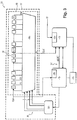
- the measurement module 13 comprises a master microcontroller 15, a slave microcontroller 16, an FPGA 17 and a memory 18.
- the master microcontroller 15 comprises a temperature measurement unit 20, which acquires fluid temperature measurements made by a temperature sensor located in the duct or near the duct.
- the slave microcontroller 16 comprises a 12-bit analog-to-digital converter 21.
- the master microcontroller 15 and the slave microcontroller 16 are connected by a communication channel 22 which is here an SPI (for Serial Peripheral Interface ) bus.
- SPI Serial Peripheral Interface
- the master microcontroller 15 is connected to the FPGA 17.
- the first transducer 12a and the second transducer 12b each successively fulfill the function of a transmitter of ultrasonic measurement signals Se, and the function of a receiver of received ultrasonic measurement signals Sr.
- the measurement module 13 thus supplies the transmitter with electrical signals which the latter transforms into ultrasonic measurement signals Se.
- Signals electrical signals are rectangular signals 24 here.
- the measurement module 13 acquires the received ultrasonic measurement signals Sr which are received by the receiver.
- the transmitter transmits the ultrasonic measurement signals Se at a transmission frequency fus.
- the frequency fus is conventionally between 900kHz and 4MHz, and is here equal to 1MHz.
- the ultrasonic measurement signals thus travel between the first transducer 12a and the second transducer 12b, a path of defined length L from upstream to downstream and downstream to upstream.
- the path of defined length is here a rectilinear path between the first transducer 12a and the second transducer 12b.
- the ultrasonic measurement signal therefore travels the path of defined length from upstream to downstream.
- the ultrasonic measurement signal Se is emitted by the transmitter with a level NE.
- the received ultrasonic measurement signal Sr is received by the receiver with an NR level lower than the NE level.
- the measurement module 13 produces a travel time measurement representative of a time taken by the ultrasonic measurement signal Se to travel the path of defined length L from upstream to downstream, then produces a travel time measurement representative of a time taken by the ultrasonic measurement signal Se to travel the path of defined length L from downstream to upstream, then finally evaluates the speed of the water as a function of these travel time measurements.
- the figure 4 first of all represents an ultrasonic measurement signal received Sr1 which is received by the measurement module 13 after having traveled the path of defined length L from upstream to downstream.
- the receiver activates reception at a time T0, synchronized with the emission of the ultrasonic measurement signal. Pairing the transmitter and receiver makes this synchronization possible.
- the travel time measurement from upstream to downstream is obtained from the determination of a moment of occurrence T1 of a predetermined lobe of the received ultrasonic measurement signal Sr1.
- the moment of occurrence T1 is here the moment when a predetermined falling edge of the lobe occurs.
- the moment of occurrence T1 is an instant of passage through zero which is measured by a method of the “ Zero Crossing” type.
- the predetermined lobe is a j th lobe of the received ultrasonic measurement signal Sr1 after an amplitude of the received ultrasonic measurement signal Sr1 has exceeded, at time T2, a predetermined amplitude threshold Sa.
- the j th lobe is in the occurrence here the fourth lobe 25.
- the figure 4 also represents a received ultrasonic measurement signal Sr2 which is received by the measurement module 13 after having traveled the path of defined length L from downstream to upstream.
- the downstream upstream travel time measurement is obtained from the determination of a moment of occurrence T'1 of the fourth lobe 26 of the received ultrasonic measurement signal Sr2.
- the speed of the water is then evaluated by the measurement module 13 as a function of the measurement of travel time from upstream to downstream and the measurement of travel time from downstream to upstream.
- the water velocity is proportional to a difference between the downstream upstream travel time measurement and the upstream to downstream travel time measurement.
- the measured water speed is an average speed of water in the diameter of the pipe, the speed of the water masses being in fact different at center of the duct and near the walls of the duct.
- One of the aims of the measurement method is to obtain a very precise measurement of the moments of occurrence T1 and T'1.
- Each ultrasonic measurement signal received Sr is acquired by the slave microcontroller 16 of the measurement module 13.
- the analog-to-digital converter 21 of the slave microcontroller 16 digitizes a measurement portion of the received ultrasonic measurement signal Sr.
- the measuring portion corresponds to the fourth lobe defined above.
- the measurement module 13 controls the moment of emission of the ultrasonic measurement signal Se and can therefore estimate a time interval during which the fourth lobe is acquired.
- the analog-to-digital converter 21 samples the received ultrasonic measurement signal Sr. at 4 MHz.
- the slave microcontroller 16 estimates an offset of the four measurement samples by calculating an average of the four measurement samples.
- the offset is subtracted for each measurement sample.
- the offset can be determined on the arithmetic mean of all samples on the previous measurement.
- the slave microcontroller 16 estimates an amplitude of the measurement portion, that is to say of the fourth lobe, from the measurement samples.
- the estimation of the amplitude of the fourth lobe therefore consists in calculating the value a mes .
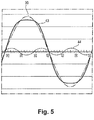
- the slave microcontroller 16 will then access the reference samples contained in a pre-filled reference table stored in the memory 18.
- the reference samples form a reference curve.
- the reference curve is here a period of a reference sinusoid 30 of frequency 1 MHz, which corresponds to the frequency fus of the ultrasonic measurement signal Se and therefore of the received ultrasonic measurement signal Sr.
- Two reference samples are spaced here 50ps temporally, so that 20,000 reference samples are stored in memory 18.
- the slave microcontroller 16 calculates a ratio between the amplitude of the reference sinusoid 30 and the amplitude of the fourth lobe, and adjusts the measurement samples A k by multiplying them by said ratio.
- the slave microcontroller 16 therefore produces adjusted measurement samples.
- the reference sinusoid 30 constitutes a sinusoidal interpolation of the adjusted measurement samples and therefore of the measurement samples, except that a unit time shift exists between each adjusted measurement sample and the reference sinusoid 30.
- the unit time shift corresponds to the phase of each adjusted measurement sample, that is to say to the phase ⁇ mentioned earlier.
- the unit time offset is different according to the adjusted measurement samples and depends in particular on a jitter in the timing of the sampling.
- the unit time offset is estimated as follows.
- the value of the adjusted measurement sample is necessarily located between the values of two reference samples.
- the slave microcontroller 16 therefore performs a linear interpolation or a quadratic interpolation of any order n, to obtain a reference time, on the reference sinusoid, with which the value of the adjusted measurement sample is associated.
- the unit time offset corresponds to the difference between the reference time and the measurement time at which the measurement sample was acquired from which the adjusted measurement sample resulted.
- a zero crossing time of the fourth lobe is estimated.
- This estimation uses the unit time shift and the reference samples of the reference sine wave 30.
- the unit time shift makes it possible to set the reference sine wave 30 on the adjusted measurement sample.
- the slave microcontroller 16 therefore uses the reference samples shifted by a delay equal to the unit time shift to determine the instant of zero crossing. The determination of the instant of crossing through zero therefore uses “ideal” reference samples which have not undergone any jitter type disturbances.
- a final estimate of the zero crossing instant is obtained by averaging the four zero crossing instants.
- the measurement module 13 then calculates an average of the unit time shifts to obtain an overall time shift, corresponding to an shift between the measurement portion and the reference sinusoid 30.
- the measurement method then consists in shifting, for the following acquisitions, the sampling of the measurement portion of the received ultrasonic measurement signal Sr by a sampling delay equal to the overall time shift.
- the adjusted measurement samples will coincide with “ideal” reference samples of the reference sinusoid 30.
- the sampling offset consists in shifting the clock signal CLK which rates the analog-to-digital converter 21 of the slave microcontroller 16.
- a control block 32 and a delay generation block 33 are programmed for this purpose in the FPGA 17.
- the delay generation block 33 comprises a chain 35 of N delay stages and a multiplexer 36.
- Each delay stage comprises two inverters connected in series. Each of the N delay stages is designated by its position from left to right in the chain. The output of each k th delay stage is connected to the input of the k + 1 th delay stage.
- the FPGA 17 receives the clock signal CLK.
- the clock signal CLK is applied to the input of the first delay stage, ie to the input of the chain 35 of the N delay stages.
- the multiplexer 36 has N inputs E1 ... EN each connected to the output of one of the delay stages, and an output S.
- the multiplexer 36 also receives N control signals 38.
- Each control signal 38 is associated with one stage behind. All the control signals are at 1, except one of the control signals 38 which is at 0.
- the output of the delay stage associated with the control signal 38 which is at 0 is applied to the output S of the multiplexer 36
- the output S of the multiplexer 36 is connected to the slave microcontroller 16.
- each delay stage is associated with a different determined delay applied to the clock signal CLK.
- the delays determined have been calibrated in the factory and are memorized by the master microcontroller 15.
- the slave microcontroller 16 therefore acquires the measurement portion of the received ultrasonic signal Sr, which is digitized by the analog-to-digital converter 21.
- the slave microcontroller 16 defines the global time offset, and transmits to the master microcontroller 15 the value of the global time offset via the communication channel 22.
- the master microcontroller 15 then applies to the clock signal CLK a sampling delay equal to the global time offset by programming the control block 32 which produces the control signals 38.
- the control signals 38 control the multiplexer 36 so that the output of the delay stage applied to the output S of the multiplexer 36 is associated with a determined delay equal to the overall time offset.
- the master microcontroller 15 then reinitializes the slave microcontroller 16, thanks to a RESET signal.
- the slave microcontroller 16 then uses, for the next sampling, a shifted clock signal CLK '.
- the shifted clock signal CLK ' corresponds to the clock signal CLK delayed by a sampling delay equal to the global time shift.
- the slave microcontroller 16 then directly determines, for each adjusted measurement sample, a zero crossing instant from the reference samples. A final estimate of the zero crossing instant is obtained by averaging the four zero crossing instants.
- the travel time is then estimated from the instant of zero crossing.
- the slave microcontroller 16 further improves the accuracy of the travel time measurements.
- the improvement in the precision of the travel time measurements consists first of all in calculating an average M 'of a number n of travel time measurements.
- the number n is here equal to 80.
- X is a predetermined percentage of the mean M '.
- X is advantageously between 3% and 30% of M ′.
- X is here equal to 20% of M '.
- M is calculated, which is the average of the travel time measurements 41 within the range [M'-20%; M '+ 20%].
- the accuracy of the travel time measurement is thus further significantly improved.
- the final precision obtained is conventionally between 10ps and 20ps.
- the speed of the fluid is then obtained from the difference between the travel time from upstream to downstream and the travel time from downstream to upstream.
- the reference curve does not necessarily include a sinusoidal period: a quarter of a period would be sufficient.
- the reference curve can also have a shape other than sinusoidal.
- the memory 18 can for example contain reference samples of pseudo-sinusoidal curves such as the pseudo-sinusoidal curve 43. Each pseudo-sinusoidal curve 43 is sampled at 50 ps.
- Each pseudo-sinusoidal curve 43 is obtained by adding to the sinusoid 30 one or more additional curves 44.
- An additional curve 44 is in this case a curve of the third harmonic of the 1 MHz frequency (that is to say of the frequency of the ultrasonic measurement signal).
- the choice of the reference curve can then depend on the temperature of the fluid.
- the master microcontroller 15 acquires, via the temperature measurement unit 20, the temperature of the fluid.
- the master microcontroller 15 selects in the memory 18 the reference curve whose profile corresponds to the profile of the measurement portion of the ultrasonic measurement signal received at said fluid temperature.
- the method for measuring a speed of a fluid uses a single microcontroller.
- the measurement method is then purely digital, and does not consist in applying a sampling delay to the clock signal of the analog-to-digital converter.
- the microcontroller of the measurement module again evaluates a unit time shift between each adjusted measurement sample and the reference curve.
- the unit time shift is evaluated by linear interpolation or by n-order quadratic interpolation.
- the microcontroller For each adjusted measurement sample, the microcontroller then “holds” the reference curve on the adjusted measurement sample, estimates the instant of zero crossing, and shifts the instant of zero crossing by the unit time offset. A final estimate of the zero crossing instant is obtained by averaging the four zero crossing instants. The fluid velocity is generated from the final estimate of the zero crossing instant, and these operations are reproduced for each ultrasonic measurement signal received.
- the measurement method according to the second embodiment requires fewer hardware components than the measurement method according to the first embodiment.
- the measurement method according to the second embodiment requires performing linear or quadratic interpolations of order n on each new acquisition of a measurement portion of a received ultrasonic measurement signal.
- the method for measuring a speed of a fluid according to a third embodiment again uses a single microcontroller.
- the measurement process is again purely digital.
- the measurement method consists in acquiring and digitizing a first received ultrasonic measurement signal, acquired by the measurement module after having traveled the path of defined length from upstream to downstream.
- a sinusoidal lobe interpolation is then carried out by lobe allowing the received signal to be oversampled.
- the sinusoidal interpolation again uses reference samples contained in a pre-populated reference table stored in memory.
- a number p of first measurement samples a1 i is thus obtained (i varies here between 1 and p).
- the first measurement samples are spaced 50ps apart in time.
- the measurement method then consists in acquiring and digitizing a second received ultrasonic measurement signal, acquired by the measurement module after having traveled the path of defined length from downstream to upstream.
- the first samples a1 i are therefore delayed in the case where m> 0 (and advanced in the case where m ⁇ 0), in this formula, by m ⁇ 50 ps with respect to the second samples a2 i + m .
- the first received ultrasonic measurement signal which is delayed by m ⁇ 50 ps, and the second received ultrasonic measurement signal, are in phase.
- the value of m which maximizes the cross-correlation function therefore gives a time shift between the first ultrasonic measurement signal received and the second ultrasonic measurement signal received.
- the time offset corresponds to the DToF, by which the average speed of the fluid is estimated.
- each delay stage could include an asynchronous D flip-flop.
- Ultrasonic measurement signals can be emitted with an orientation at any angle relative to a longitudinal axis of the duct.
- Ultrasonic measurement signals can be reflected by reflectors, for example by mirrors oriented at 45 °.
Claims (15)
- Messverfahren zum Messen einer Geschwindigkeit eines Fluids, umfassend die Schritte:- Senden eines Ultraschallmesssignals (Se);- Erfassen und Digitalisieren eines Messabschnitts (25, 26) eines empfangenen Ultraschallmesssignals (Sr, Sr1, Sr2), nachdem das Ultraschallmesssignal (Se) eine Strecke definierter Länge (L) zurückgelegt hat, um Messproben zu erhalten;- Schätzen einer Amplitude des Messabschnitts anhand der Messproben;- Zugreifen auf Referenzproben einer vorgefüllten und in einem Speicher gespeicherten Referenztabelle, wobei die Referenzproben eine Referenzkurve bilden, die eine Interpolation der Messproben darstellt;- Erzeugen von angepassten Messproben, indem die Messproben mit einem Verhältnis zwischen einer Amplitude der Referenzkurve (30, 43) und der Amplitude des Messabschnitts multipliziert wird;- für jede angepasste Messprobe, Bestimmen einer unitären zeitlichen Verschiebung zwischen der angepassten Messprobe und der Referenzkurve;- für jede angepasste Messprobe, Schätzen einer Null-Durchgangszeit des Messabschnitts anhand der unitären zeitlichen Verschiebung und der Referenzproben;- Schätzen anhand eines Mittelwertes der Null-Durchgangszeiten einer Streckenzeitmessung des Ultraschallmesssignals zum Zurücklegen der Strecke definierter Länge;- Schätzen der Geschwindigkeit des Fluids anhand der Streckenzeitmessung.
- Messverfahren nach Anspruch 1, bei dem die unitäre zeitliche Verschiebung bestimmt wird, indem eine lineare Interpolation oder eine quadratische Interpolation der Ordnung n auf der Basis der Referenzproben durchgeführt wird.
- Messverfahren nach Anspruch 1, ferner umfassend die Schritte des Messens einer Temperatur des Fluids und des Auswählens in Abhängigkeit von der Temperatur des Fluids der Referenzkurve unter einer Vielzahl von gespeicherten Referenzkurven.
- Messverfahren nach Anspruch 1 ferner umfassend einen vorbereitenden Schritt bestehend aus dem Schätzen und dem Abziehen von den Messproben eines Offsets der genannten Messproben.
- Messverfahren nach Anspruch 1, ferner umfassend den Schritt des Anwendens an einer Abtastung des Messabschnitts einer Abtastverzögerung gleich einem Mittelwert der unitären zeitlichen Verschiebungen.
- Messverfahren nach Anspruch 5, bei dem die Anwendung der Abtastverzögerung darin besteht, ein Taktsignal (CLK) zu verzögern, das einen Analog-Digital-Umwandler (21) taktet, der den Messabschnitt digitalisiert.
- Messverfahren nach Anspruch 6, umfassend zum Verzögern des Taktsignals die Schritte:- Anlegen des Taktsignals am Eingang einer Kette (35), die aus einer Vielzahl von Verzögerungsstufen gebildet ist, wobei der Ausgang jeder Verzögerungsstufe mit einer vorbestimmten Verzögerung verknüpft ist;- Auswählen des Ausgangs der Verzögerungsstufe, deren bestimmte Verzögerungsstufe der Abtastverzögerung entspricht.
- Messverfahren nach Anspruch 7, bei dem ein Multiplexer (36) sowie die Kette (35), die aus der Vielzahl von Verzögerungsstufen gebildet ist, in einem FPGA (17) programmiert sind, wobei der Multiplexer (36) verwendet wird, um die Auswahl des Ausgangs der Verzögerungsstufe durchzuführen.
- Messverfahren nach Anspruch 1, ferner umfassend die Schritte:- Durchführen einer Vielzahl von Streckenzeitmessungen;- Berechnen eines Mittelwerts M' der Streckenzeitmessungen;- Entfernen ungenauer Streckenzeitmessungen (40), die sich außerhalb eines Bereichs [M'-X; M'+X] befinden;- Berechnen eines Mittelwerts M der Streckenzeitmessungen (41) innerhalb des Bereichs [M'-X; M'+X];- Schätzen der Geschwindigkeit des Fluids anhand des Mittelwerts M.
- Messverfahren nach Anspruch 1, umfassend die Schritte:- Senden eines ersten Ultraschallmesssignals und eines zweiten Ultraschallmesssignals;- Erfassen und Digitalisieren eines ersten Messabschnitts eines empfangenen ersten Ultraschallmesssignals, nachdem das erste Ultraschallmesssignal eine Strecke definierter Länge von stromaufwärts nach stromabwärts zurückgelegt hat, um erste Messproben zu erhalten;- Erfassen und Digitalisieren eines zweiten Messabschnitts eines empfangenen zweiten Ultraschallmesssignals, nachdem das zweite Ultraschallmesssignal die Strecke definierter Länge von stromabwärts nach stromaufwärts zurückgelegt hat, um zweite Messproben zu erhalten;- Maximieren einer Kreuzkorrelationsfunktion zwischen den ersten Messproben und den zweiten Messproben, um eine Streckenzeitdifferenz zu erhalten;- Schätzen der Geschwindigkeit des Fluids anhand der Streckenzeitdifferenz.
- Ultraschall-Fluidzähler, umfassend einen ersten Wandler (12a), einen zweiten Wandler (12b) und ein Messmodul (13), das ein Master-Mikrosteuergerät (15), ein Slave-Mikrosteuergerät (16) und ein FPGA (17) umfasst, in dem ein Verzögerungserzeugungsblock (33) programmiert ist, wobei der Ultraschall-Fluidzähler ausgebildet ist, um das Messverfahren nach einem der vorhergehenden Ansprüche durchzuführen.
- Ultraschall-Fluidzähler nach Anspruch 11, bei dem der Verzögerungserzeugungsblock einen Multiplexer (36) und eine Kette (35) umfasst, die aus einer Vielzahl von Verzögerungsstufen gebildet ist, wobei der Ausgang jeder Verzögerungsstufe mit einer bestimmten Verzögerung verknüpft und mit einem Eingang des Multiplexers verbunden ist.
- Ultraschall-Fluidzähler nach Anspruch 12, bei dem das Slave-Mikrosteuergerät einen Analog-Digital-Wandler umfasst, der den Messabschnitt digitalisiert, wobei ein Taktsignal am Eingang der Kette angelegt wird, wobei das Master-Mikrosteuergerät den Multiplexer steuert und wobei sich ein versetztes Taktsignal (CLK') am Ausgang des Multiplexers befindet und zum Takten des Analog-Digital-Wandlers verwendet wird.
- Computerprogramm, umfassend Anweisungen zum Durchführen des Messverfahrens nach einem der Ansprüche 1 bis 10 mittels eines Mikrosteuergerätes eines Ultraschall-Fluidzählers.
- Speichermittel, die dadurch gekennzeichnet sind, dass sie ein Computerprogramm speichern, das Anweisungen zum Durchführen des Messverfahrens nach einem der Ansprüche 1 bis 10 mittels eines Mikrosteuergeräts eines Ultraschall-Fluidzählers umfasst.
Priority Applications (1)
| Application Number | Priority Date | Filing Date | Title |
|---|---|---|---|
| PL18731495T PL3645981T3 (pl) | 2017-06-27 | 2018-06-22 | Sposób pomiaru prędkości płynu |
Applications Claiming Priority (2)
| Application Number | Priority Date | Filing Date | Title |
|---|---|---|---|
| FR1755910A FR3068126B1 (fr) | 2017-06-27 | 2017-06-27 | Procede de mesure d'une vitesse d'un fluide |
| PCT/EP2018/066810 WO2019002145A1 (fr) | 2017-06-27 | 2018-06-22 | Procede de mesure d'une vitesse d'un fluide |
Publications (2)
| Publication Number | Publication Date |
|---|---|
| EP3645981A1 EP3645981A1 (de) | 2020-05-06 |
| EP3645981B1 true EP3645981B1 (de) | 2021-08-04 |
Family
ID=59521130
Family Applications (1)
| Application Number | Title | Priority Date | Filing Date |
|---|---|---|---|
| EP18731495.0A Active EP3645981B1 (de) | 2017-06-27 | 2018-06-22 | Verfahren zur messung einer geschwindigkeit eines fluids |
Country Status (7)
| Country | Link |
|---|---|
| US (1) | US11199429B2 (de) |
| EP (1) | EP3645981B1 (de) |
| CN (1) | CN110799810B (de) |
| CA (1) | CA3067467C (de) |
| FR (1) | FR3068126B1 (de) |
| PL (1) | PL3645981T3 (de) |
| WO (1) | WO2019002145A1 (de) |
Families Citing this family (4)
| Publication number | Priority date | Publication date | Assignee | Title |
|---|---|---|---|---|
| FR3097968B1 (fr) * | 2019-06-28 | 2021-06-18 | Sagemcom Energy & Telecom Sas | Procédé de mesure de la vitesse d’un fluide |
| FR3098599B1 (fr) * | 2019-07-12 | 2021-08-06 | Sagemcom Energy & Telecom Sas | Procédé de mesure de la vitesse d’un fluide |
| CN111964738B (zh) * | 2020-08-14 | 2022-10-11 | 中国计量大学 | 一种基于超声回波信号相似度的动态阈值设置方法 |
| FR3116115B1 (fr) * | 2020-11-09 | 2022-10-28 | Sagemcom Energy & Telecom Sas | Procédé de mesure de la température de l’eau dans un compteur |
Family Cites Families (26)
| Publication number | Priority date | Publication date | Assignee | Title |
|---|---|---|---|---|
| US4456376A (en) * | 1981-04-06 | 1984-06-26 | Lear Siegler, Inc. | Optical rate sensor |
| US4782697A (en) * | 1986-07-31 | 1988-11-08 | Williams 3Rd Albert J | Acoustic current meter |
| DE19611233A1 (de) * | 1996-03-21 | 1997-09-25 | Siemens Ag | Verfahren zur Laufzeitmessung eines elektrischen, elektromagnetischen oder akustischen Signals |
| US5748504A (en) * | 1996-06-12 | 1998-05-05 | Welch Allyn, Inc. | Calibration method for use with ultrasonic flowmeters |
| DE19722274A1 (de) * | 1997-05-28 | 1998-12-03 | Degussa | Verfahren zur Messung von Dichte und Massenstrom |
| AUPQ061399A0 (en) * | 1999-05-27 | 1999-06-17 | University Of Sydney, The | Acoustic flow meters |
| CA2422504C (en) * | 2000-09-15 | 2012-01-24 | Radian Research, Inc. | Methods and apparatus for analog-to-digital conversion |
| CN100449276C (zh) * | 2002-08-05 | 2009-01-07 | 松下电器产业株式会社 | 流量计量装置 |
| US6950768B2 (en) * | 2003-09-08 | 2005-09-27 | Daniel Industries, Inc. | Self-tuning ultrasonic meter |
| DE102004025243A1 (de) * | 2004-05-22 | 2005-12-08 | Robert Bosch Gmbh | Bestimmung des Empfangszeitpunkts eines Ultraschallsignals mittels Pulsformerfassung |
| DE102005025884A1 (de) * | 2005-06-06 | 2006-12-07 | Robert Bosch Gmbh | Verfahren und Vorrichtung zur Korrektur eines Signals eines Sensors |
| CA2701759C (en) * | 2007-10-08 | 2016-03-08 | Micro Motion, Inc. | A flow device and method for operating a flow device |
| CN102062623B (zh) * | 2010-11-09 | 2012-06-20 | 郭荣岭 | 消除零点误差的超声波流量计 |
| US8700344B2 (en) * | 2011-04-20 | 2014-04-15 | Neptune Technology Group Inc. | Ultrasonic flow meter |
| EP2587227A1 (de) * | 2011-10-31 | 2013-05-01 | Welltec A/S | Bohrlochwerkzeug zur Bestimmung der Flussgeschwindigkeit |
| DE102011089231A1 (de) * | 2011-12-20 | 2013-06-20 | Endress + Hauser Gmbh + Co. Kg | Verfahren und Messgerät zur Füllstandsmessung |
| EP2626676B1 (de) * | 2012-02-08 | 2016-04-20 | VEGA Grieshaber KG | Vorrichtung und Verfahren zum Korrigieren eines Offsets |
| JP2013185891A (ja) * | 2012-03-07 | 2013-09-19 | Tokyo Institute Of Technology | 超音波流量計測装置および超音波流量計測方法 |
| US9689726B2 (en) * | 2012-07-09 | 2017-06-27 | Texas Instruments Incorporated | Flow meter |
| CN102829831A (zh) * | 2012-08-27 | 2012-12-19 | 曲宝源 | 球形膨胀腔低压损立柱式超声波流量计基表 |
| CN103090916B (zh) * | 2013-02-22 | 2015-03-18 | 呼和浩特市睿城科技有限责任公司 | 一种超声波流量测量装置及其测量方法 |
| US9569405B2 (en) * | 2014-04-30 | 2017-02-14 | Google Inc. | Generating correlation scores |
| US10801868B2 (en) * | 2014-06-10 | 2020-10-13 | Texas Instruments Incorporated | Extended range ADC flow meter |
| CN104697593B (zh) * | 2015-03-24 | 2017-12-08 | 合肥工业大学 | 一种基于fpga和dsp的气体超声流量计 |
| US10309813B2 (en) * | 2015-05-15 | 2019-06-04 | Reliance Worldwide Corporation | Method and system for fluid flow rate measurement |
| US10817588B2 (en) * | 2016-10-24 | 2020-10-27 | Xia Llc | Ratio-reference measurement of the arrival time and/or amplitude of a digitized electronic pulse |
-
2017
- 2017-06-27 FR FR1755910A patent/FR3068126B1/fr not_active Expired - Fee Related
-
2018
- 2018-06-22 EP EP18731495.0A patent/EP3645981B1/de active Active
- 2018-06-22 WO PCT/EP2018/066810 patent/WO2019002145A1/fr unknown
- 2018-06-22 CN CN201880042944.1A patent/CN110799810B/zh active Active
- 2018-06-22 US US16/627,072 patent/US11199429B2/en active Active
- 2018-06-22 PL PL18731495T patent/PL3645981T3/pl unknown
- 2018-06-22 CA CA3067467A patent/CA3067467C/fr active Active
Also Published As
| Publication number | Publication date |
|---|---|
| CA3067467A1 (fr) | 2019-01-03 |
| US20200141777A1 (en) | 2020-05-07 |
| CN110799810A (zh) | 2020-02-14 |
| PL3645981T3 (pl) | 2022-01-17 |
| FR3068126B1 (fr) | 2019-08-30 |
| US11199429B2 (en) | 2021-12-14 |
| CA3067467C (fr) | 2021-11-30 |
| CN110799810B (zh) | 2021-11-30 |
| EP3645981A1 (de) | 2020-05-06 |
| BR112019027733A2 (pt) | 2020-09-15 |
| WO2019002145A1 (fr) | 2019-01-03 |
| FR3068126A1 (fr) | 2018-12-28 |
Similar Documents
| Publication | Publication Date | Title |
|---|---|---|
| EP3645981B1 (de) | Verfahren zur messung einer geschwindigkeit eines fluids | |
| EP0225667B1 (de) | Gerät zur Ultraschallechographie der Bewegung von Körperorganen, insbesondere der Blutströmung oder des Herzens | |
| FR2772929A1 (fr) | Appareil radar meteorologique | |
| EP1097354B1 (de) | Kreuzmessen von akustischen signalen eines durchflussmessers | |
| FR2604081A1 (fr) | Dispositif d'exploration par echographie ultrasonore d'organes en mouvement et d'ecoulements sanguins | |
| FR2699686A1 (fr) | Procédé de mesure de la distance et de la vitesse d'objets. | |
| EP0338618B1 (de) | Gerät zur Messung der Geschwindigkeit von Organen und der Blutströmung durch Korrelationsverfahren | |
| EP3615894B1 (de) | Verfahren zur messung einer geschwindigkeit eines fluids | |
| EP2309289B1 (de) | Verfahren zum Trennen von verschachtelten Radar-Puls-Folgen | |
| EP3811109A1 (de) | Verfahren zur messung der wellenhöhe mittels eines luftradars | |
| EP1113247A1 (de) | Verfahren und Vorrichtung zur Messung einer Flüssigkeitsströmung in einer Rohrleitung | |
| EP3593148B1 (de) | Verfahren, flüssigkeitsmessgerät, computerprogramm und speichermittel zur messung einer geschwindigkeit eines fluids | |
| WO2006000668A1 (fr) | Dispositif et procédé de caractérisation dimensionnelle d'un objet cylindrique. | |
| FR2715725A1 (fr) | Procédé et dispositif de détermination d'un paramètre physique représenté par l'évolution au cours du temps d'une grandeur physique. | |
| EP3605145B1 (de) | Hochauflösendes fernverarbeitungsverfahren | |
| FR2913773A1 (fr) | Dispositif de reception de signaux satellitaires comprenant une boucle de phase avec compensation des retards | |
| EP3757578B1 (de) | Verfahren zur messung der geschwindigkeit eines fluids mithilfe von ultraschall | |
| EP3764104A1 (de) | Verfahren zur messung der geschwindigkeit eines fluids, ultraschallfluidmeter, computerprogramm und speichermittel | |
| EP3995800B1 (de) | Verfahren zur messung der wassertemperatur in einem zähler | |
| EP3721237B1 (de) | Verfahren, flüssigkeitsmessgerät, computerprogramm und speichermittel zur messung einer geschwindigkeit eines fluids | |
| FR2972055A1 (fr) | Procede de determination d'un rang d'ambiguite en distance d'un signal recu par un radar doppler a impulsions | |
| FR2951279A1 (fr) | Procede et dispositif pour ameliorer la mesure d'un temps de parcours d'un signal d'ultrasons | |
| FR2590790A1 (fr) | Appareil d'exploration par echographie ultrasonore de milieux en mouvement et notamment d'ecoulements sanguins ou d'organes tels que le coeur | |
| BR112019027733B1 (pt) | Método para medir uma velocidade de um fluido | |
| FR2475233A1 (fr) | Recepteur indicateur numerique electronique pour systeme de radionavigation |
Legal Events
| Date | Code | Title | Description |
|---|---|---|---|
| STAA | Information on the status of an ep patent application or granted ep patent |
Free format text: STATUS: UNKNOWN |
|
| STAA | Information on the status of an ep patent application or granted ep patent |
Free format text: STATUS: THE INTERNATIONAL PUBLICATION HAS BEEN MADE |
|
| PUAI | Public reference made under article 153(3) epc to a published international application that has entered the european phase |
Free format text: ORIGINAL CODE: 0009012 |
|
| STAA | Information on the status of an ep patent application or granted ep patent |
Free format text: STATUS: REQUEST FOR EXAMINATION WAS MADE |
|
| 17P | Request for examination filed |
Effective date: 20191223 |
|
| AK | Designated contracting states |
Kind code of ref document: A1 Designated state(s): AL AT BE BG CH CY CZ DE DK EE ES FI FR GB GR HR HU IE IS IT LI LT LU LV MC MK MT NL NO PL PT RO RS SE SI SK SM TR |
|
| AX | Request for extension of the european patent |
Extension state: BA ME |
|
| DAV | Request for validation of the european patent (deleted) | ||
| DAX | Request for extension of the european patent (deleted) | ||
| GRAP | Despatch of communication of intention to grant a patent |
Free format text: ORIGINAL CODE: EPIDOSNIGR1 |
|
| STAA | Information on the status of an ep patent application or granted ep patent |
Free format text: STATUS: GRANT OF PATENT IS INTENDED |
|
| INTG | Intention to grant announced |
Effective date: 20210217 |
|
| GRAS | Grant fee paid |
Free format text: ORIGINAL CODE: EPIDOSNIGR3 |
|
| GRAA | (expected) grant |
Free format text: ORIGINAL CODE: 0009210 |
|
| STAA | Information on the status of an ep patent application or granted ep patent |
Free format text: STATUS: THE PATENT HAS BEEN GRANTED |
|
| AK | Designated contracting states |
Kind code of ref document: B1 Designated state(s): AL AT BE BG CH CY CZ DE DK EE ES FI FR GB GR HR HU IE IS IT LI LT LU LV MC MK MT NL NO PL PT RO RS SE SI SK SM TR |
|
| REG | Reference to a national code |
Ref country code: GB Ref legal event code: FG4D Free format text: NOT ENGLISH |
|
| REG | Reference to a national code |
Ref country code: AT Ref legal event code: REF Ref document number: 1417418 Country of ref document: AT Kind code of ref document: T Effective date: 20210815 |
|
| REG | Reference to a national code |
Ref country code: CH Ref legal event code: EP |
|
| REG | Reference to a national code |
Ref country code: DE Ref legal event code: R096 Ref document number: 602018021230 Country of ref document: DE |
|
| REG | Reference to a national code |
Ref country code: IE Ref legal event code: FG4D Free format text: LANGUAGE OF EP DOCUMENT: FRENCH |
|
| REG | Reference to a national code |
Ref country code: LT Ref legal event code: MG9D |
|
| REG | Reference to a national code |
Ref country code: NL Ref legal event code: MP Effective date: 20210804 |
|
| REG | Reference to a national code |
Ref country code: AT Ref legal event code: MK05 Ref document number: 1417418 Country of ref document: AT Kind code of ref document: T Effective date: 20210804 |
|
| PG25 | Lapsed in a contracting state [announced via postgrant information from national office to epo] |
Ref country code: PT Free format text: LAPSE BECAUSE OF FAILURE TO SUBMIT A TRANSLATION OF THE DESCRIPTION OR TO PAY THE FEE WITHIN THE PRESCRIBED TIME-LIMIT Effective date: 20211206 Ref country code: NO Free format text: LAPSE BECAUSE OF FAILURE TO SUBMIT A TRANSLATION OF THE DESCRIPTION OR TO PAY THE FEE WITHIN THE PRESCRIBED TIME-LIMIT Effective date: 20211104 Ref country code: AT Free format text: LAPSE BECAUSE OF FAILURE TO SUBMIT A TRANSLATION OF THE DESCRIPTION OR TO PAY THE FEE WITHIN THE PRESCRIBED TIME-LIMIT Effective date: 20210804 Ref country code: BG Free format text: LAPSE BECAUSE OF FAILURE TO SUBMIT A TRANSLATION OF THE DESCRIPTION OR TO PAY THE FEE WITHIN THE PRESCRIBED TIME-LIMIT Effective date: 20211104 Ref country code: LT Free format text: LAPSE BECAUSE OF FAILURE TO SUBMIT A TRANSLATION OF THE DESCRIPTION OR TO PAY THE FEE WITHIN THE PRESCRIBED TIME-LIMIT Effective date: 20210804 Ref country code: SE Free format text: LAPSE BECAUSE OF FAILURE TO SUBMIT A TRANSLATION OF THE DESCRIPTION OR TO PAY THE FEE WITHIN THE PRESCRIBED TIME-LIMIT Effective date: 20210804 Ref country code: RS Free format text: LAPSE BECAUSE OF FAILURE TO SUBMIT A TRANSLATION OF THE DESCRIPTION OR TO PAY THE FEE WITHIN THE PRESCRIBED TIME-LIMIT Effective date: 20210804 Ref country code: FI Free format text: LAPSE BECAUSE OF FAILURE TO SUBMIT A TRANSLATION OF THE DESCRIPTION OR TO PAY THE FEE WITHIN THE PRESCRIBED TIME-LIMIT Effective date: 20210804 Ref country code: ES Free format text: LAPSE BECAUSE OF FAILURE TO SUBMIT A TRANSLATION OF THE DESCRIPTION OR TO PAY THE FEE WITHIN THE PRESCRIBED TIME-LIMIT Effective date: 20210804 Ref country code: HR Free format text: LAPSE BECAUSE OF FAILURE TO SUBMIT A TRANSLATION OF THE DESCRIPTION OR TO PAY THE FEE WITHIN THE PRESCRIBED TIME-LIMIT Effective date: 20210804 |
|
| PG25 | Lapsed in a contracting state [announced via postgrant information from national office to epo] |
Ref country code: LV Free format text: LAPSE BECAUSE OF FAILURE TO SUBMIT A TRANSLATION OF THE DESCRIPTION OR TO PAY THE FEE WITHIN THE PRESCRIBED TIME-LIMIT Effective date: 20210804 Ref country code: GR Free format text: LAPSE BECAUSE OF FAILURE TO SUBMIT A TRANSLATION OF THE DESCRIPTION OR TO PAY THE FEE WITHIN THE PRESCRIBED TIME-LIMIT Effective date: 20211105 |
|
| PG25 | Lapsed in a contracting state [announced via postgrant information from national office to epo] |
Ref country code: NL Free format text: LAPSE BECAUSE OF FAILURE TO SUBMIT A TRANSLATION OF THE DESCRIPTION OR TO PAY THE FEE WITHIN THE PRESCRIBED TIME-LIMIT Effective date: 20210804 |
|
| PG25 | Lapsed in a contracting state [announced via postgrant information from national office to epo] |
Ref country code: DK Free format text: LAPSE BECAUSE OF FAILURE TO SUBMIT A TRANSLATION OF THE DESCRIPTION OR TO PAY THE FEE WITHIN THE PRESCRIBED TIME-LIMIT Effective date: 20210804 |
|
| REG | Reference to a national code |
Ref country code: DE Ref legal event code: R097 Ref document number: 602018021230 Country of ref document: DE |
|
| PG25 | Lapsed in a contracting state [announced via postgrant information from national office to epo] |
Ref country code: SM Free format text: LAPSE BECAUSE OF FAILURE TO SUBMIT A TRANSLATION OF THE DESCRIPTION OR TO PAY THE FEE WITHIN THE PRESCRIBED TIME-LIMIT Effective date: 20210804 Ref country code: SK Free format text: LAPSE BECAUSE OF FAILURE TO SUBMIT A TRANSLATION OF THE DESCRIPTION OR TO PAY THE FEE WITHIN THE PRESCRIBED TIME-LIMIT Effective date: 20210804 Ref country code: RO Free format text: LAPSE BECAUSE OF FAILURE TO SUBMIT A TRANSLATION OF THE DESCRIPTION OR TO PAY THE FEE WITHIN THE PRESCRIBED TIME-LIMIT Effective date: 20210804 Ref country code: EE Free format text: LAPSE BECAUSE OF FAILURE TO SUBMIT A TRANSLATION OF THE DESCRIPTION OR TO PAY THE FEE WITHIN THE PRESCRIBED TIME-LIMIT Effective date: 20210804 Ref country code: CZ Free format text: LAPSE BECAUSE OF FAILURE TO SUBMIT A TRANSLATION OF THE DESCRIPTION OR TO PAY THE FEE WITHIN THE PRESCRIBED TIME-LIMIT Effective date: 20210804 Ref country code: AL Free format text: LAPSE BECAUSE OF FAILURE TO SUBMIT A TRANSLATION OF THE DESCRIPTION OR TO PAY THE FEE WITHIN THE PRESCRIBED TIME-LIMIT Effective date: 20210804 |
|
| PLBE | No opposition filed within time limit |
Free format text: ORIGINAL CODE: 0009261 |
|
| STAA | Information on the status of an ep patent application or granted ep patent |
Free format text: STATUS: NO OPPOSITION FILED WITHIN TIME LIMIT |
|
| 26N | No opposition filed |
Effective date: 20220506 |
|
| PG25 | Lapsed in a contracting state [announced via postgrant information from national office to epo] |
Ref country code: IT Free format text: LAPSE BECAUSE OF FAILURE TO SUBMIT A TRANSLATION OF THE DESCRIPTION OR TO PAY THE FEE WITHIN THE PRESCRIBED TIME-LIMIT Effective date: 20210804 |
|
| PG25 | Lapsed in a contracting state [announced via postgrant information from national office to epo] |
Ref country code: SI Free format text: LAPSE BECAUSE OF FAILURE TO SUBMIT A TRANSLATION OF THE DESCRIPTION OR TO PAY THE FEE WITHIN THE PRESCRIBED TIME-LIMIT Effective date: 20210804 |
|
| PG25 | Lapsed in a contracting state [announced via postgrant information from national office to epo] |
Ref country code: MC Free format text: LAPSE BECAUSE OF FAILURE TO SUBMIT A TRANSLATION OF THE DESCRIPTION OR TO PAY THE FEE WITHIN THE PRESCRIBED TIME-LIMIT Effective date: 20210804 |
|
| REG | Reference to a national code |
Ref country code: CH Ref legal event code: PL |
|
| REG | Reference to a national code |
Ref country code: BE Ref legal event code: MM Effective date: 20220630 |
|
| PG25 | Lapsed in a contracting state [announced via postgrant information from national office to epo] |
Ref country code: LU Free format text: LAPSE BECAUSE OF NON-PAYMENT OF DUE FEES Effective date: 20220622 Ref country code: LI Free format text: LAPSE BECAUSE OF NON-PAYMENT OF DUE FEES Effective date: 20220630 Ref country code: IE Free format text: LAPSE BECAUSE OF NON-PAYMENT OF DUE FEES Effective date: 20220622 Ref country code: CH Free format text: LAPSE BECAUSE OF NON-PAYMENT OF DUE FEES Effective date: 20220630 |
|
| PG25 | Lapsed in a contracting state [announced via postgrant information from national office to epo] |
Ref country code: BE Free format text: LAPSE BECAUSE OF NON-PAYMENT OF DUE FEES Effective date: 20220630 |
|
| PGFP | Annual fee paid to national office [announced via postgrant information from national office to epo] |
Ref country code: FR Payment date: 20230523 Year of fee payment: 6 Ref country code: DE Payment date: 20230523 Year of fee payment: 6 |
|
| PGFP | Annual fee paid to national office [announced via postgrant information from national office to epo] |
Ref country code: PL Payment date: 20230524 Year of fee payment: 6 |
|
| PGFP | Annual fee paid to national office [announced via postgrant information from national office to epo] |
Ref country code: GB Payment date: 20230523 Year of fee payment: 6 |