EP3645409B1 - Improvements in or relating to lid arrangements - Google Patents
Improvements in or relating to lid arrangements Download PDFInfo
- Publication number
- EP3645409B1 EP3645409B1 EP18750472.5A EP18750472A EP3645409B1 EP 3645409 B1 EP3645409 B1 EP 3645409B1 EP 18750472 A EP18750472 A EP 18750472A EP 3645409 B1 EP3645409 B1 EP 3645409B1
- Authority
- EP
- European Patent Office
- Prior art keywords
- lid
- lids
- container
- rib formations
- edge
- Prior art date
- Legal status (The legal status is an assumption and is not a legal conclusion. Google has not performed a legal analysis and makes no representation as to the accuracy of the status listed.)
- Active
Links
Images


Classifications
-
- B—PERFORMING OPERATIONS; TRANSPORTING
- B65—CONVEYING; PACKING; STORING; HANDLING THIN OR FILAMENTARY MATERIAL
- B65D—CONTAINERS FOR STORAGE OR TRANSPORT OF ARTICLES OR MATERIALS, e.g. BAGS, BARRELS, BOTTLES, BOXES, CANS, CARTONS, CRATES, DRUMS, JARS, TANKS, HOPPERS, FORWARDING CONTAINERS; ACCESSORIES, CLOSURES, OR FITTINGS THEREFOR; PACKAGING ELEMENTS; PACKAGES
- B65D43/00—Lids or covers for rigid or semi-rigid containers
- B65D43/14—Non-removable lids or covers
- B65D43/16—Non-removable lids or covers hinged for upward or downward movement
- B65D43/163—Non-removable lids or covers hinged for upward or downward movement the container and the lid being made separately
- B65D43/164—Non-removable lids or covers hinged for upward or downward movement the container and the lid being made separately and connected by interfitting hinge elements integrally with the container and the lid formed respectively
- B65D43/165—Non-removable lids or covers hinged for upward or downward movement the container and the lid being made separately and connected by interfitting hinge elements integrally with the container and the lid formed respectively these elements being assembled by a separate pin-like member
-
- B—PERFORMING OPERATIONS; TRANSPORTING
- B65—CONVEYING; PACKING; STORING; HANDLING THIN OR FILAMENTARY MATERIAL
- B65D—CONTAINERS FOR STORAGE OR TRANSPORT OF ARTICLES OR MATERIALS, e.g. BAGS, BARRELS, BOTTLES, BOXES, CANS, CARTONS, CRATES, DRUMS, JARS, TANKS, HOPPERS, FORWARDING CONTAINERS; ACCESSORIES, CLOSURES, OR FITTINGS THEREFOR; PACKAGING ELEMENTS; PACKAGES
- B65D21/00—Nestable, stackable or joinable containers; Containers of variable capacity
- B65D21/02—Containers specially shaped, or provided with fittings or attachments, to facilitate nesting, stacking, or joining together
- B65D21/06—Containers specially shaped, or provided with fittings or attachments, to facilitate nesting, stacking, or joining together with movable parts adapted to be placed in alternative positions for nesting the containers when empty and for stacking them when full
- B65D21/064—Containers specially shaped, or provided with fittings or attachments, to facilitate nesting, stacking, or joining together with movable parts adapted to be placed in alternative positions for nesting the containers when empty and for stacking them when full the movable parts being an attached or integral cover made of one or two pieces
-
- B—PERFORMING OPERATIONS; TRANSPORTING
- B65—CONVEYING; PACKING; STORING; HANDLING THIN OR FILAMENTARY MATERIAL
- B65D—CONTAINERS FOR STORAGE OR TRANSPORT OF ARTICLES OR MATERIALS, e.g. BAGS, BARRELS, BOTTLES, BOXES, CANS, CARTONS, CRATES, DRUMS, JARS, TANKS, HOPPERS, FORWARDING CONTAINERS; ACCESSORIES, CLOSURES, OR FITTINGS THEREFOR; PACKAGING ELEMENTS; PACKAGES
- B65D1/00—Rigid or semi-rigid containers having bodies formed in one piece, e.g. by casting metallic material, by moulding plastics, by blowing vitreous material, by throwing ceramic material, by moulding pulped fibrous material or by deep-drawing operations performed on sheet material
- B65D1/22—Boxes or like containers with side walls of substantial depth for enclosing contents
-
- B—PERFORMING OPERATIONS; TRANSPORTING
- B65—CONVEYING; PACKING; STORING; HANDLING THIN OR FILAMENTARY MATERIAL
- B65D—CONTAINERS FOR STORAGE OR TRANSPORT OF ARTICLES OR MATERIALS, e.g. BAGS, BARRELS, BOTTLES, BOXES, CANS, CARTONS, CRATES, DRUMS, JARS, TANKS, HOPPERS, FORWARDING CONTAINERS; ACCESSORIES, CLOSURES, OR FITTINGS THEREFOR; PACKAGING ELEMENTS; PACKAGES
- B65D43/00—Lids or covers for rigid or semi-rigid containers
- B65D43/14—Non-removable lids or covers
- B65D43/16—Non-removable lids or covers hinged for upward or downward movement
-
- B—PERFORMING OPERATIONS; TRANSPORTING
- B65—CONVEYING; PACKING; STORING; HANDLING THIN OR FILAMENTARY MATERIAL
- B65D—CONTAINERS FOR STORAGE OR TRANSPORT OF ARTICLES OR MATERIALS, e.g. BAGS, BARRELS, BOTTLES, BOXES, CANS, CARTONS, CRATES, DRUMS, JARS, TANKS, HOPPERS, FORWARDING CONTAINERS; ACCESSORIES, CLOSURES, OR FITTINGS THEREFOR; PACKAGING ELEMENTS; PACKAGES
- B65D2251/00—Details relating to container closures
- B65D2251/10—Details of hinged closures
- B65D2251/1083—Closures formed of several sections hinged to the container or base
Definitions
- This invention relates to lid arrangements. This invention also relates to lids. More particularly, but not exclusively, this invention relates to containers incorporating lid arrangements.
- Containers are locked shut by the use of straps secured around them.
- the hinge pins of known containers can be removed to allow illicit access to the contents.
- the lids of known containers have a tendency to deform inwardly when a weight, such as a full container, is placed on the lids when closed.
- US 5 328 048 A discloses a tote box style container including in which a pair of lids are hingedly connected to an upper portion of the sidewalls of the container along one edge of each lid.
- the lids include a force distributing rib extending in spaced parallel relation to the hinged edge of the lids along a portion of the length of the lids and downwardly from the underside of the lids when the lids are in the closed position such that the rib is in adjacent abutting relation to the interior of the sidewall above the shelf and such that the distal end of the rib is in contact with the shelf to distribute loads placed on the container through the sidewalls to the base of the container.
- US 2016/122076 A1 which accords with the preamble of appended claim 1, discloses a closing system for tamper proof boxes for transporting products which is comprised of a rectangular-shaped box, two lids provided with hinges that are attached to both the box and the lids and have specially reinforced inner pins that also fit into the hinges through a lower opening.
- Two of the pins are independently inserted into each hinge, the main body of which has a trapezoidal conformation with a cylindrical tip at the end thereof that is inserted into the holes of the fixed hinges of the box.
- Two small oblong slits are provided on the opposite sides of the lids and coincidental with two other slits of the box that are provided on the upper edge thereof. Another slit is respectively provided on the same side of the box that is coincidental with a further slit of the lid that is perpendicular to the first mentioned slits.
- a lid arrangement comprising:
- Adjacent rib formations of the first lid may define therebetween a first recess extending from the free edge of the first lid.
- Adjacent rib formations of the second lid may define therebetween a second recess extending from the free edge of the second lid.
- the first projecting portion provided by the first lid may be received by the second recess of the second lid when the lids are in their closed positions.
- the second projecting portion provided by the second lid may be received by the first recess of the first lid when the lids are in their closed positions.
- the container may comprise an upstanding wall and a hinge arrangement on the wall.
- the lid arrangement may be attached to the upstanding wall at the hinge arrangement.
- the hinge arrangement may comprise a hinge element aligned with the hinge member of the hinge portion.
- the hinge pin may extend through the hinge element to secure the lid to the container.
- the hinge arrangement may comprise a plurality of the hinge elements.
- the hinge arrangement may comprise a second hinge element aligned with the second hinge member of the hinge portion.
- the second hinge pin may extend through the second hinge element to secure the lid to the container.
- the hinge arrangement may comprise a plurality of the second hinge elements.
- the container may comprise a further of the aforesaid upstanding walls opposite the aforesaid upstanding wall.
- the container may further include a further hinge arrangement on the further upstanding wall.
- a further of the aforesaid lid arrangements may be attached to the further upstanding wall at the further hinge arrangement.
- Adjacent rib formations of each of the first and second lids may define a respective further recess therebetween, said further recess extending from the hinged edge.
- the rib formations defining the further recesses may taper towards each other from the hinged edge.
- each lid may be aligned with the first or second projecting portion.
- the rib formations providing the first and second projecting portions may define the further recesses.
- the further recess of each of the first and second lids may receive a projecting portion of a lid of another container nested in the first mentioned container.
- Each of the first and second lids comprises a main part.
- the hinged edge may be an edge of the main part.
- the free edge may be another edge of the main part.
- the rib formations may extend across the main part.
- the adjacent rib formations defining the first recess may taper towards each other from the free edge of the first lid.
- the adjacent rib formations defining the second recess may taper towards each other from the free edge of the second lid.
- the first projecting portion may extend outwardly from the free edge of the first lid.
- the adjacent rib formations providing the first projecting portion may taper towards each other outwardly from the free edge of the first lid.
- the second projecting portion may extend outwardly from the free edge of the second lid.
- the adjacent rib formations providing the second projecting portion may taper towards each other outwardly from the free edge of the second lid.
- the projecting portions of each of the first and second lids may extend across the free edge of the other of the first and second lids.
- each rib formation of the first lid may overlap the lids of the second lid.
- each rib formation of the first lid may extend parallel to, and alongside, a corresponding rib formation of the second lid to provide a line of support that extends across the lid arrangement from the hinged edge of the first lid to the hinged edge of the second lid.
- the rib formations may comprise strengthening ribs.
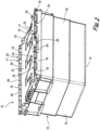
- Figures 1 to 7 show a container assembly 10 comprising a container 12 and two lid arrangements 20 thereon.
- the container 12 comprises a base 14 and four upstanding side walls 16.
- Two of the side walls 16 arranged opposite each other are provided with respective hinge arrangements 17 to allow the lid arrangements 20 to be pivotally attached thereto.
- the lid arrangements 20 comprise lids 22 that are pivotally movable between an open position shown in Figure 1 and a closed position shown in Figure 2 .
- Each of the hinge arrangements 17 comprises a plurality of hinge elements 18.
- Each of the lid arrangements 20 also includes first and second hinge pins 24 to pivotally attach the lid 22 to a respective one of the hinge arrangements 17 of the container 12.
- Each lid 22 has opposite first and second side edges 23A, 23B and a hinge portion 25 extending between the side edges 23A, 23B.
- the hinge portion 25 has a central region 28 and a plurality of hinge members 26 through which the hinge pins 24 extend.
- a plurality of first hinge members 26 extend from the central region 28 to the first side edge 23A.
- the first hinge pin 24 extends through the first hinge members 26.
- a plurality of second hinge members 26 extend from the central region 28 to the second side edge 23B. The second hinge pin 24 extends through the second hinge members 26.
- the first and second hinge members 26 on each lid 22 are aligned with the hinge elements 18 on the respective upstanding walls 16. This allows the hinge pins 24 to extend through the hinge members 26 and the hinge elements 18, to provide a hinge attaching the lids 22 to the upstanding walls 16.
- Each hinge member 26 has a pivot element 30 at each of its opposite ends through which the hinge pin 24 extends to allow the lid 22 to pivot from between its open and closed positions.
- Each of the pivot elements 30 comprises a web portion 32 extending across the end of the hinge member 26, the web portion 32 defining an aperture 34 through which the hinge pin 24 extends.
- each lid 22 further include first and second cover members 36 within the central region 28.
- the cover members 36 extend over one end of the respective first and second hinge pins 24.
- Each cover member 36 comprises a shroud 38 defining an opening 40 to allow insertion and removal of the hinge pins 24 when the lids 22 are in their open positions.
- Each cover member 36 has one of the aforesaid pivot elements 30 at each end thereof.
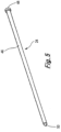
- one of the hinge pins 24 is shown, which comprises an elongate member 46 having opposite ends.
- a radially outwardly extending end stop member 48 is provided at one of the ends of the elongate member 46.
- the end stop member 48 is in the form of a flange.
- a pointed tip 50 is provided at the opposite end of the elongate member 46.
- Each cover member 36 defines a receiving space 44 in which the end stop member 48 is received.
- the receiving space 44 has an internal sloping surface 42 to facilitate insertion and removal of the hinge pin 24 through the opening 40.
- the opening 40 is arranged so that, when the lid 22 is in the closed condition, the opening 40 is closed by an upper edge of the wall 16, thereby preventing removal of the hinge pin 24 through the opening 40.
- the hinge pins 24 are inserted through the hinge elements 18 and the hinge members 26 via the cover members 36 when the lids 22 are in their open positions.
- the sloping surfaces 42 act as guide surfaces to guide the hinge pins 24 through the hinge members 26 and hinge elements 18.
- the end stop member 48 When each hinge pin 24 is inserted into the hinge members 26 and hinge elements 18, the end stop member 48 is received in the receiving space 44 defined by the cover member 36.
- the end stop members 48 are wider than the aperture 34 in the pivot portion of the cover member 36.
- hinge pins 24 cannot be removed by pulling them at the tip 50 through the hinge members 26 and the hinge elements 18.
- the only way to remove the hinge pins 24 is by pulling the end stop members 48 through the openings 40 defined by the cover members 36
- the shroud 38 extends over the end stop member 48 thereby preventing access to the end stop member 48.
- the lids 22 are secured in their closed position, e.g. by a strap wrapped around the container 12 arrangement, access to the end stop member 48 is not possible, thereby preventing unauthorised removal of the hinge pins 24.
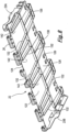
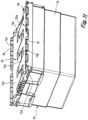
- FIGS 6 and 8 to 11 show embodiments of a lid arrangement 100 (see Figures 9 , 10 and 11 ) comprising first and second lids 22, 22A.
- Each of the first and second lids 22, 22A has a substantially flat main part 122 having a hinged edge 124 comprising the hinge members 26.
- the main part 122 of each of the first and second lids 22, 22A also has a free edge 126 opposite the hinged edge 124.
- the main part 122 has a lower face 128 and an upper face 130.
- Each of the lids 22,22A comprise a plurality of rib formations in the form of strengthening ribs 132 extending across the lids 22, 22A.
- the strengthening ribs 132 extend obliquely from the hinged edge 124 across the main part 122 to the free edge 126.
- the strengthening ribs 132 extend at an angle of between 82° and 87° from the hinged edge 124. A typical angle is substantially 85°. Adjacent strengthening ribs 132 are slanted in opposite directions across the main part 122.
- Adjacent strengthening ribs 132 of the first lid 22 define therebetween a plurality of first recesses 134 in the upper face 130.
- the first recesses 134 extend inwardly from the free edge 126 of the first lid 22 across the main part 122.
- adjacent strengthening ribs 132 of the second lid 22A define therebetween a plurality of second recesses 136.
- the second recesses 136 extend from the free edge 126 of the second lid 22A across the main part 122.
- Adjacent strengthening ribs 132 of the first lid 22 provide a plurality of first projecting portions 138 extending outwardly from the free edge 126 of the first lid 22.
- Adjacent strengthening ribs 132 of the second lid 22A provide a plurality of second projecting portions 140 at the free edge 126 of the second lid 22A. The projecting portions extend outwardly beyond the free edge 126 of the first and second lids 22, 22A.
- Each of the first and second lids 22, 22A is pivotally movable about the hinge members 26 from an open position of each of the first and second lids 22, 22A to a closed position of each of the first and second lids 22, 22A.
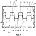
- first and second lids 22, 22A When the first and second lids 22, 22A are in their closed positions, the first projecting portions 138 of the first lid 22 are received in the second recesses 136 of the second lid 22A, and the second projecting portions 140 of the second lid 22A are received in the first recesses 134 of the first lid 22, as shown in Figures 9 and 11 . This has the effect of securing the first and second lids 22, 22A to each other.
- one of the strengthening ribs of the first lid 22 is designated 132
- one of the strengthening ribs of the second lid 22A is designated 132A.
- the first projecting portion 138 of the first lid 22 is shown in broken lines, and is received in the second recess 136 of the second lid 22A.
- the strengthening rib 132 of the first lid 22 extends parallel to the strengthening rib 132A of the second lid 22A. In the region of the first projecting portion 138, the strengthening rib 132 lies alongside the strengthening rib 132A. In the arrangement shown in Figure 12 , the strengthening ribs 132 and 132A are in near alignment and create a line of support shown by a broken line and designated S.
- the line of support S extends along both of the strengthening ribs 132, 132A and helps to prevent the lid 22, 22A from collapsing inwards.
- a plurality of lines of support S are created along both lids 22, 22A, thereby increasing the strength of the lids 22, 22A over lids of prior art containers.
- the strengthening ribs 132 providing the first and second projecting portions 138, 140 define further recesses 142 extending inwardly from the hinged edge 124 of each of the lids 22, 22A.
- the strengthening ribs 132 defining the further recesses are slanted towards each other so that the further recesses 142 are wider than the projecting portions 138, 140.
- the purpose of the further recesses 142 is to reduce the amount of space occupied by the containers 10 when they are nested within one another.
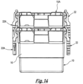
- Two nesting containers namely a lower container 10, and an upper container 10A, are shown in Figures 13 and 14 .
- the lids 22, 22A of the containers 10, 10A are in their open positions.
- the lids 22, 22A hang down from the upper edges of the containers 10, 10A in the open positions of the lids 22, 22A.
- the second projecting portions 140 of the lids 22A of the upper container 10A are received in the further recesses 142 defined by the lid 22A of the lower container 10, but this is not visible in the drawings.
- the receiving of the projecting portions 138 and 140 in the further recesses 142 has the effect, as shown in Figure 14 of minimising the extent to which the lids 22, 22A splay outwardly from the walls 16, thereby minimising the required storage space for each array of nested containers.
- first and second recesses 136, 134 and first and second projecting portions 138, 140 that increase the strength of the lids 22, 22A when the lids are in their closed positions, and which, by virtue of the further recesses 142 allows the containers to be nested occupying minimal space.
Landscapes
- Engineering & Computer Science (AREA)
- Mechanical Engineering (AREA)
- Ceramic Engineering (AREA)
- Closures For Containers (AREA)
Applications Claiming Priority (3)
| Application Number | Priority Date | Filing Date | Title |
|---|---|---|---|
| GBGB1710462.1A GB201710462D0 (en) | 2017-06-29 | 2017-06-29 | Improvements in or relating to lid arrangements |
| GB1810524.7A GB2567033B (en) | 2017-06-29 | 2018-06-27 | Interlocking lids with reinforcing ribs for stackable nestable containers |
| PCT/GB2018/000100 WO2019002804A1 (en) | 2017-06-29 | 2018-06-28 | IMPROVEMENTS IN OR RELATING TO LID ARRANGEMENTS |
Publications (3)
| Publication Number | Publication Date |
|---|---|
| EP3645409A1 EP3645409A1 (en) | 2020-05-06 |
| EP3645409B1 true EP3645409B1 (en) | 2024-01-03 |
| EP3645409C0 EP3645409C0 (en) | 2024-01-03 |
Family
ID=59592652
Family Applications (1)
| Application Number | Title | Priority Date | Filing Date |
|---|---|---|---|
| EP18750472.5A Active EP3645409B1 (en) | 2017-06-29 | 2018-06-28 | Improvements in or relating to lid arrangements |
Country Status (7)
| Country | Link |
|---|---|
| US (1) | US11338965B2 (pl) |
| EP (1) | EP3645409B1 (pl) |
| CA (1) | CA3064350A1 (pl) |
| ES (1) | ES2972668T3 (pl) |
| GB (2) | GB201710462D0 (pl) |
| PL (1) | PL3645409T3 (pl) |
| WO (1) | WO2019002804A1 (pl) |
Families Citing this family (1)
| Publication number | Priority date | Publication date | Assignee | Title |
|---|---|---|---|---|
| GB201909080D0 (en) * | 2019-06-25 | 2019-08-07 | Gripple Ltd | Hinge arrangement |
Citations (1)
| Publication number | Priority date | Publication date | Assignee | Title |
|---|---|---|---|---|
| US20160122076A1 (en) * | 2014-11-05 | 2016-05-05 | Belazza Empreendimentos e Participações S.A. | Closing System For Tamper Proof BOXES FOR TRANSPORTING PRODUCTS |
Family Cites Families (20)
| Publication number | Priority date | Publication date | Assignee | Title |
|---|---|---|---|---|
| FR1404760A (fr) * | 1964-05-04 | 1965-07-02 | Beacon Plastic & Metal Prod | Dispositif de fermeture d'un récipient |
| US3463345A (en) * | 1968-08-28 | 1969-08-26 | Ms Ind Inc | Lidded tote box |
| US3655088A (en) * | 1970-06-01 | 1972-04-11 | Theodor Box | High-impact plastic carrying and stacking case with hinged cover |
| US4161261A (en) * | 1978-05-05 | 1979-07-17 | Menasha Corporation | Security container |
| US4364489A (en) * | 1980-04-28 | 1982-12-21 | Nestier Canada Inc. | Container lid |
| US4688675A (en) * | 1985-02-27 | 1987-08-25 | Buckhorn Material Handling Group, Inc. | Nesting box with reduced lid flares |
| US5328048A (en) * | 1993-02-08 | 1994-07-12 | Otto Industries, Inc. | Tote box |
| US5673791A (en) * | 1994-10-04 | 1997-10-07 | Buckhorn Material Handling Group, Inc. | Container and lid for container |
| CA2268998C (en) * | 1999-04-13 | 2002-12-17 | Ipl Inc. | A lidded container for lobsters or like crustacean |
| US6041931A (en) * | 1999-04-20 | 2000-03-28 | Ipl Inc. | Lidded container for lobsters or like crustacean |
| US6315154B1 (en) * | 2000-03-15 | 2001-11-13 | Delta Consolidated Industries | Double-wall blow-molded article with pinned hinge |
| EP1428764B1 (de) * | 2002-12-13 | 2006-06-28 | Georg Utz Holding AG | Stapelbehälter |
| US7841487B2 (en) * | 2004-11-01 | 2010-11-30 | Buckhorn, Inc. | Molded container with hinged lids having a knuckle and pin connection |
| US8066143B2 (en) * | 2005-02-22 | 2011-11-29 | Rehrig Pacific Company | Storage container with hinged lid |
| DE202005013351U1 (de) * | 2005-08-24 | 2005-11-10 | Fritz Schäfer GmbH | Behälter, insbesondere Lager-, Stapel- und Transportbehälter |
| GB2471969B (en) * | 2008-09-12 | 2011-05-11 | Loadhog Ltd | Nest and stack container and Load Securing System |
| GB0816753D0 (en) * | 2008-09-12 | 2008-10-22 | Loadhog Ltd | Load securing system |
| JP5348666B2 (ja) * | 2010-06-01 | 2013-11-20 | 三甲株式会社 | 蓋付きコンテナ |
| US9926112B2 (en) * | 2011-04-25 | 2018-03-27 | Daniel Greenberg | Containment system and adaptive sealing systems therefore with collapsible feature and methods for operating the same |
| GB201400437D0 (en) * | 2014-01-10 | 2014-02-26 | Loadhog Ltd | Container |
-
2017
- 2017-06-29 GB GBGB1710462.1A patent/GB201710462D0/en not_active Ceased
-
2018
- 2018-06-27 GB GB1810524.7A patent/GB2567033B/en active Active
- 2018-06-28 US US16/615,711 patent/US11338965B2/en active Active
- 2018-06-28 PL PL18750472.5T patent/PL3645409T3/pl unknown
- 2018-06-28 EP EP18750472.5A patent/EP3645409B1/en active Active
- 2018-06-28 ES ES18750472T patent/ES2972668T3/es active Active
- 2018-06-28 WO PCT/GB2018/000100 patent/WO2019002804A1/en not_active Ceased
- 2018-06-28 CA CA3064350A patent/CA3064350A1/en active Pending
Patent Citations (1)
| Publication number | Priority date | Publication date | Assignee | Title |
|---|---|---|---|---|
| US20160122076A1 (en) * | 2014-11-05 | 2016-05-05 | Belazza Empreendimentos e Participações S.A. | Closing System For Tamper Proof BOXES FOR TRANSPORTING PRODUCTS |
Also Published As
| Publication number | Publication date |
|---|---|
| ES2972668T3 (es) | 2024-06-13 |
| WO2019002804A1 (en) | 2019-01-03 |
| GB2567033A (en) | 2019-04-03 |
| GB201810524D0 (en) | 2018-08-15 |
| GB2567033B (en) | 2021-12-01 |
| GB201710462D0 (en) | 2017-08-16 |
| PL3645409T3 (pl) | 2024-05-06 |
| US11338965B2 (en) | 2022-05-24 |
| EP3645409A1 (en) | 2020-05-06 |
| CA3064350A1 (en) | 2019-01-03 |
| US20200172301A1 (en) | 2020-06-04 |
| EP3645409C0 (en) | 2024-01-03 |
Similar Documents
| Publication | Publication Date | Title |
|---|---|---|
| CA1109405A (en) | Security container | |
| US11325749B2 (en) | Container with removable tray | |
| US5074461A (en) | Container | |
| US8167166B2 (en) | Container | |
| US8261933B2 (en) | Container | |
| US7284673B2 (en) | Locking structure for hinged container | |
| US8091731B2 (en) | Container | |
| RU135624U1 (ru) | Упаковочная коробка | |
| US5992673A (en) | Reusable produce crate | |
| US20130334241A1 (en) | Container lid | |
| EP2492216B1 (en) | Egg package | |
| US20100282752A1 (en) | Produce container | |
| EP3215434B1 (en) | Two-piece container lid | |
| EP3645409B1 (en) | Improvements in or relating to lid arrangements | |
| EP2776327B1 (en) | A carton | |
| US11155388B2 (en) | Covered storage bin | |
| US7980453B2 (en) | Apparatus and method for handles integrated with product containers | |
| US20040173629A1 (en) | Reusable hinged-lid shipping/storage box | |
| KR200477098Y1 (ko) | 덮개에 스토퍼가 부가된 포장용 케이스 | |
| FI99201C (fi) | Kannettava kuluttajapakkaus | |
| WO2018011563A1 (en) | Closure mechanism for a foldable container |
Legal Events
| Date | Code | Title | Description |
|---|---|---|---|
| STAA | Information on the status of an ep patent application or granted ep patent |
Free format text: STATUS: UNKNOWN |
|
| STAA | Information on the status of an ep patent application or granted ep patent |
Free format text: STATUS: THE INTERNATIONAL PUBLICATION HAS BEEN MADE |
|
| PUAI | Public reference made under article 153(3) epc to a published international application that has entered the european phase |
Free format text: ORIGINAL CODE: 0009012 |
|
| STAA | Information on the status of an ep patent application or granted ep patent |
Free format text: STATUS: REQUEST FOR EXAMINATION WAS MADE |
|
| 17P | Request for examination filed |
Effective date: 20200108 |
|
| AK | Designated contracting states |
Kind code of ref document: A1 Designated state(s): AL AT BE BG CH CY CZ DE DK EE ES FI FR GB GR HR HU IE IS IT LI LT LU LV MC MK MT NL NO PL PT RO RS SE SI SK SM TR |
|
| AX | Request for extension of the european patent |
Extension state: BA ME |
|
| DAV | Request for validation of the european patent (deleted) | ||
| DAX | Request for extension of the european patent (deleted) | ||
| STAA | Information on the status of an ep patent application or granted ep patent |
Free format text: STATUS: EXAMINATION IS IN PROGRESS |
|
| 17Q | First examination report despatched |
Effective date: 20220628 |
|
| REG | Reference to a national code |
Ref country code: DE Ref legal event code: R079 Free format text: PREVIOUS MAIN CLASS: B65D0021060000 Ipc: B65D0001220000 Ref document number: 602018063614 Country of ref document: DE |
|
| RIC1 | Information provided on ipc code assigned before grant |
Ipc: B65D 1/22 20060101AFI20230404BHEP |
|
| GRAP | Despatch of communication of intention to grant a patent |
Free format text: ORIGINAL CODE: EPIDOSNIGR1 |
|
| STAA | Information on the status of an ep patent application or granted ep patent |
Free format text: STATUS: GRANT OF PATENT IS INTENDED |
|
| INTG | Intention to grant announced |
Effective date: 20230525 |
|
| GRAJ | Information related to disapproval of communication of intention to grant by the applicant or resumption of examination proceedings by the epo deleted |
Free format text: ORIGINAL CODE: EPIDOSDIGR1 |
|
| STAA | Information on the status of an ep patent application or granted ep patent |
Free format text: STATUS: EXAMINATION IS IN PROGRESS |
|
| REG | Reference to a national code |
Ref country code: DE Ref legal event code: R079 Free format text: PREVIOUS MAIN CLASS: B65D0001220000 Ipc: B65D0021060000 Ref country code: DE Ref legal event code: R079 Ref document number: 602018063614 Country of ref document: DE Free format text: PREVIOUS MAIN CLASS: B65D0001220000 Ipc: B65D0021060000 |
|
| INTC | Intention to grant announced (deleted) | ||
| RIC1 | Information provided on ipc code assigned before grant |
Ipc: B65D 1/22 20060101ALI20230824BHEP Ipc: B65D 43/16 20060101ALI20230824BHEP Ipc: B65D 21/06 20060101AFI20230824BHEP |
|
| GRAP | Despatch of communication of intention to grant a patent |
Free format text: ORIGINAL CODE: EPIDOSNIGR1 |
|
| STAA | Information on the status of an ep patent application or granted ep patent |
Free format text: STATUS: GRANT OF PATENT IS INTENDED |
|
| INTG | Intention to grant announced |
Effective date: 20231010 |
|
| GRAS | Grant fee paid |
Free format text: ORIGINAL CODE: EPIDOSNIGR3 |
|
| GRAA | (expected) grant |
Free format text: ORIGINAL CODE: 0009210 |
|
| STAA | Information on the status of an ep patent application or granted ep patent |
Free format text: STATUS: THE PATENT HAS BEEN GRANTED |
|
| AK | Designated contracting states |
Kind code of ref document: B1 Designated state(s): AL AT BE BG CH CY CZ DE DK EE ES FI FR GB GR HR HU IE IS IT LI LT LU LV MC MK MT NL NO PL PT RO RS SE SI SK SM TR |
|
| REG | Reference to a national code |
Ref country code: GB Ref legal event code: FG4D |
|
| REG | Reference to a national code |
Ref country code: DE Ref legal event code: R096 Ref document number: 602018063614 Country of ref document: DE |
|
| REG | Reference to a national code |
Ref country code: CH Ref legal event code: EP |
|
| REG | Reference to a national code |
Ref country code: IE Ref legal event code: FG4D |
|
| U01 | Request for unitary effect filed |
Effective date: 20240124 |
|
| U07 | Unitary effect registered |
Designated state(s): AT BE BG DE DK EE FI FR IT LT LU LV MT NL PT SE SI Effective date: 20240131 |
|
| REG | Reference to a national code |
Ref country code: ES Ref legal event code: FG2A Ref document number: 2972668 Country of ref document: ES Kind code of ref document: T3 Effective date: 20240613 |
|
| PG25 | Lapsed in a contracting state [announced via postgrant information from national office to epo] |
Ref country code: IS Free format text: LAPSE BECAUSE OF FAILURE TO SUBMIT A TRANSLATION OF THE DESCRIPTION OR TO PAY THE FEE WITHIN THE PRESCRIBED TIME-LIMIT Effective date: 20240503 |
|
| PG25 | Lapsed in a contracting state [announced via postgrant information from national office to epo] |
Ref country code: GR Free format text: LAPSE BECAUSE OF FAILURE TO SUBMIT A TRANSLATION OF THE DESCRIPTION OR TO PAY THE FEE WITHIN THE PRESCRIBED TIME-LIMIT Effective date: 20240404 |
|
| U20 | Renewal fee for the european patent with unitary effect paid |
Year of fee payment: 7 Effective date: 20240613 |
|
| PG25 | Lapsed in a contracting state [announced via postgrant information from national office to epo] |
Ref country code: HR Free format text: LAPSE BECAUSE OF FAILURE TO SUBMIT A TRANSLATION OF THE DESCRIPTION OR TO PAY THE FEE WITHIN THE PRESCRIBED TIME-LIMIT Effective date: 20240103 Ref country code: RS Free format text: LAPSE BECAUSE OF FAILURE TO SUBMIT A TRANSLATION OF THE DESCRIPTION OR TO PAY THE FEE WITHIN THE PRESCRIBED TIME-LIMIT Effective date: 20240403 |
|
| PG25 | Lapsed in a contracting state [announced via postgrant information from national office to epo] |
Ref country code: CZ Free format text: LAPSE BECAUSE OF FAILURE TO SUBMIT A TRANSLATION OF THE DESCRIPTION OR TO PAY THE FEE WITHIN THE PRESCRIBED TIME-LIMIT Effective date: 20240103 |
|
| PG25 | Lapsed in a contracting state [announced via postgrant information from national office to epo] |
Ref country code: RS Free format text: LAPSE BECAUSE OF FAILURE TO SUBMIT A TRANSLATION OF THE DESCRIPTION OR TO PAY THE FEE WITHIN THE PRESCRIBED TIME-LIMIT Effective date: 20240403 Ref country code: NO Free format text: LAPSE BECAUSE OF FAILURE TO SUBMIT A TRANSLATION OF THE DESCRIPTION OR TO PAY THE FEE WITHIN THE PRESCRIBED TIME-LIMIT Effective date: 20240403 Ref country code: IS Free format text: LAPSE BECAUSE OF FAILURE TO SUBMIT A TRANSLATION OF THE DESCRIPTION OR TO PAY THE FEE WITHIN THE PRESCRIBED TIME-LIMIT Effective date: 20240503 Ref country code: HR Free format text: LAPSE BECAUSE OF FAILURE TO SUBMIT A TRANSLATION OF THE DESCRIPTION OR TO PAY THE FEE WITHIN THE PRESCRIBED TIME-LIMIT Effective date: 20240103 Ref country code: GR Free format text: LAPSE BECAUSE OF FAILURE TO SUBMIT A TRANSLATION OF THE DESCRIPTION OR TO PAY THE FEE WITHIN THE PRESCRIBED TIME-LIMIT Effective date: 20240404 Ref country code: CZ Free format text: LAPSE BECAUSE OF FAILURE TO SUBMIT A TRANSLATION OF THE DESCRIPTION OR TO PAY THE FEE WITHIN THE PRESCRIBED TIME-LIMIT Effective date: 20240103 |
|
| REG | Reference to a national code |
Ref country code: DE Ref legal event code: R097 Ref document number: 602018063614 Country of ref document: DE |
|
| PG25 | Lapsed in a contracting state [announced via postgrant information from national office to epo] |
Ref country code: SM Free format text: LAPSE BECAUSE OF FAILURE TO SUBMIT A TRANSLATION OF THE DESCRIPTION OR TO PAY THE FEE WITHIN THE PRESCRIBED TIME-LIMIT Effective date: 20240103 |
|
| PG25 | Lapsed in a contracting state [announced via postgrant information from national office to epo] |
Ref country code: SK Free format text: LAPSE BECAUSE OF FAILURE TO SUBMIT A TRANSLATION OF THE DESCRIPTION OR TO PAY THE FEE WITHIN THE PRESCRIBED TIME-LIMIT Effective date: 20240103 |
|
| PG25 | Lapsed in a contracting state [announced via postgrant information from national office to epo] |
Ref country code: SM Free format text: LAPSE BECAUSE OF FAILURE TO SUBMIT A TRANSLATION OF THE DESCRIPTION OR TO PAY THE FEE WITHIN THE PRESCRIBED TIME-LIMIT Effective date: 20240103 Ref country code: SK Free format text: LAPSE BECAUSE OF FAILURE TO SUBMIT A TRANSLATION OF THE DESCRIPTION OR TO PAY THE FEE WITHIN THE PRESCRIBED TIME-LIMIT Effective date: 20240103 Ref country code: RO Free format text: LAPSE BECAUSE OF FAILURE TO SUBMIT A TRANSLATION OF THE DESCRIPTION OR TO PAY THE FEE WITHIN THE PRESCRIBED TIME-LIMIT Effective date: 20240103 |
|
| PLBE | No opposition filed within time limit |
Free format text: ORIGINAL CODE: 0009261 |
|
| STAA | Information on the status of an ep patent application or granted ep patent |
Free format text: STATUS: NO OPPOSITION FILED WITHIN TIME LIMIT |
|
| 26N | No opposition filed |
Effective date: 20241007 |
|
| PG25 | Lapsed in a contracting state [announced via postgrant information from national office to epo] |
Ref country code: MC Free format text: LAPSE BECAUSE OF FAILURE TO SUBMIT A TRANSLATION OF THE DESCRIPTION OR TO PAY THE FEE WITHIN THE PRESCRIBED TIME-LIMIT Effective date: 20240103 |
|
| REG | Reference to a national code |
Ref country code: CH Ref legal event code: PL |
|
| PG25 | Lapsed in a contracting state [announced via postgrant information from national office to epo] |
Ref country code: IE Free format text: LAPSE BECAUSE OF NON-PAYMENT OF DUE FEES Effective date: 20240628 |
|
| PG25 | Lapsed in a contracting state [announced via postgrant information from national office to epo] |
Ref country code: CH Free format text: LAPSE BECAUSE OF NON-PAYMENT OF DUE FEES Effective date: 20240630 |
|
| PGFP | Annual fee paid to national office [announced via postgrant information from national office to epo] |
Ref country code: PL Payment date: 20250612 Year of fee payment: 8 |
|
| PGFP | Annual fee paid to national office [announced via postgrant information from national office to epo] |
Ref country code: GB Payment date: 20250619 Year of fee payment: 8 |
|
| U20 | Renewal fee for the european patent with unitary effect paid |
Year of fee payment: 8 Effective date: 20250620 |
|
| PGFP | Annual fee paid to national office [announced via postgrant information from national office to epo] |
Ref country code: ES Payment date: 20250718 Year of fee payment: 8 |
|
| PG25 | Lapsed in a contracting state [announced via postgrant information from national office to epo] |
Ref country code: CY Free format text: LAPSE BECAUSE OF FAILURE TO SUBMIT A TRANSLATION OF THE DESCRIPTION OR TO PAY THE FEE WITHIN THE PRESCRIBED TIME-LIMIT; INVALID AB INITIO Effective date: 20180628 |