EP3645212B1 - An apparatus for supporting a heavy vehicle brake assembly - Google Patents
An apparatus for supporting a heavy vehicle brake assembly Download PDFInfo
- Publication number
- EP3645212B1 EP3645212B1 EP18822869.6A EP18822869A EP3645212B1 EP 3645212 B1 EP3645212 B1 EP 3645212B1 EP 18822869 A EP18822869 A EP 18822869A EP 3645212 B1 EP3645212 B1 EP 3645212B1
- Authority
- EP
- European Patent Office
- Prior art keywords
- drum
- assembly
- hub
- trolley
- engagement
- Prior art date
- Legal status (The legal status is an assumption and is not a legal conclusion. Google has not performed a legal analysis and makes no representation as to the accuracy of the status listed.)
- Active
Links
Images


Classifications
-
- B—PERFORMING OPERATIONS; TRANSPORTING
- B25—HAND TOOLS; PORTABLE POWER-DRIVEN TOOLS; MANIPULATORS
- B25B—TOOLS OR BENCH DEVICES NOT OTHERWISE PROVIDED FOR, FOR FASTENING, CONNECTING, DISENGAGING, OR HOLDING
- B25B11/00—Work holders not covered by any preceding group in the subclass, e.g. magnetic work holders, vacuum work holders
- B25B11/02—Assembly jigs
-
- B—PERFORMING OPERATIONS; TRANSPORTING
- B25—HAND TOOLS; PORTABLE POWER-DRIVEN TOOLS; MANIPULATORS
- B25B—TOOLS OR BENCH DEVICES NOT OTHERWISE PROVIDED FOR, FOR FASTENING, CONNECTING, DISENGAGING, OR HOLDING
- B25B27/00—Hand tools, specially adapted for fitting together or separating parts or objects whether or not involving some deformation, not otherwise provided for
- B25B27/0035—Hand tools, specially adapted for fitting together or separating parts or objects whether or not involving some deformation, not otherwise provided for for motor-vehicles
-
- B—PERFORMING OPERATIONS; TRANSPORTING
- B25—HAND TOOLS; PORTABLE POWER-DRIVEN TOOLS; MANIPULATORS
- B25B—TOOLS OR BENCH DEVICES NOT OTHERWISE PROVIDED FOR, FOR FASTENING, CONNECTING, DISENGAGING, OR HOLDING
- B25B27/00—Hand tools, specially adapted for fitting together or separating parts or objects whether or not involving some deformation, not otherwise provided for
- B25B27/02—Hand tools, specially adapted for fitting together or separating parts or objects whether or not involving some deformation, not otherwise provided for for connecting objects by press fit or detaching same
- B25B27/06—Hand tools, specially adapted for fitting together or separating parts or objects whether or not involving some deformation, not otherwise provided for for connecting objects by press fit or detaching same inserting or withdrawing sleeves or bearing races
-
- B—PERFORMING OPERATIONS; TRANSPORTING
- B62—LAND VEHICLES FOR TRAVELLING OTHERWISE THAN ON RAILS
- B62B—HAND-PROPELLED VEHICLES, e.g. HAND CARTS OR PERAMBULATORS; SLEDGES
- B62B3/00—Hand carts having more than one axis carrying transport wheels; Steering devices therefor; Equipment therefor
- B62B3/02—Hand carts having more than one axis carrying transport wheels; Steering devices therefor; Equipment therefor involving parts being adjustable, collapsible, attachable, detachable or convertible
-
- B—PERFORMING OPERATIONS; TRANSPORTING
- B62—LAND VEHICLES FOR TRAVELLING OTHERWISE THAN ON RAILS
- B62B—HAND-PROPELLED VEHICLES, e.g. HAND CARTS OR PERAMBULATORS; SLEDGES
- B62B3/00—Hand carts having more than one axis carrying transport wheels; Steering devices therefor; Equipment therefor
- B62B3/04—Hand carts having more than one axis carrying transport wheels; Steering devices therefor; Equipment therefor involving means for grappling or securing in place objects to be carried; Loading or unloading equipment
-
- B—PERFORMING OPERATIONS; TRANSPORTING
- B62—LAND VEHICLES FOR TRAVELLING OTHERWISE THAN ON RAILS
- B62B—HAND-PROPELLED VEHICLES, e.g. HAND CARTS OR PERAMBULATORS; SLEDGES
- B62B3/00—Hand carts having more than one axis carrying transport wheels; Steering devices therefor; Equipment therefor
- B62B3/10—Hand carts having more than one axis carrying transport wheels; Steering devices therefor; Equipment therefor characterised by supports specially adapted to objects of definite shape
- B62B3/104—Hand carts having more than one axis carrying transport wheels; Steering devices therefor; Equipment therefor characterised by supports specially adapted to objects of definite shape the object being of cylindrical shape, e.g. barrels, buckets, dustbins
-
- B—PERFORMING OPERATIONS; TRANSPORTING
- B66—HOISTING; LIFTING; HAULING
- B66F—HOISTING, LIFTING, HAULING OR PUSHING, NOT OTHERWISE PROVIDED FOR, e.g. DEVICES WHICH APPLY A LIFTING OR PUSHING FORCE DIRECTLY TO THE SURFACE OF A LOAD
- B66F9/00—Devices for lifting or lowering bulky or heavy goods for loading or unloading purposes
- B66F9/06—Devices for lifting or lowering bulky or heavy goods for loading or unloading purposes movable, with their loads, on wheels or the like, e.g. fork-lift trucks
-
- F—MECHANICAL ENGINEERING; LIGHTING; HEATING; WEAPONS; BLASTING
- F16—ENGINEERING ELEMENTS AND UNITS; GENERAL MEASURES FOR PRODUCING AND MAINTAINING EFFECTIVE FUNCTIONING OF MACHINES OR INSTALLATIONS; THERMAL INSULATION IN GENERAL
- F16D—COUPLINGS FOR TRANSMITTING ROTATION; CLUTCHES; BRAKES
- F16D65/00—Parts or details
- F16D65/0043—Brake maintenance and assembly, tools therefor
-
- B—PERFORMING OPERATIONS; TRANSPORTING
- B62—LAND VEHICLES FOR TRAVELLING OTHERWISE THAN ON RAILS
- B62B—HAND-PROPELLED VEHICLES, e.g. HAND CARTS OR PERAMBULATORS; SLEDGES
- B62B2202/00—Indexing codes relating to type or characteristics of transported articles
- B62B2202/02—Cylindrically-shaped articles, e.g. drums, barrels, flasks
-
- B—PERFORMING OPERATIONS; TRANSPORTING
- B62—LAND VEHICLES FOR TRAVELLING OTHERWISE THAN ON RAILS
- B62B—HAND-PROPELLED VEHICLES, e.g. HAND CARTS OR PERAMBULATORS; SLEDGES
- B62B2202/00—Indexing codes relating to type or characteristics of transported articles
- B62B2202/48—Tools
-
- B—PERFORMING OPERATIONS; TRANSPORTING
- B62—LAND VEHICLES FOR TRAVELLING OTHERWISE THAN ON RAILS
- B62B—HAND-PROPELLED VEHICLES, e.g. HAND CARTS OR PERAMBULATORS; SLEDGES
- B62B2203/00—Grasping, holding, supporting the objects
- B62B2203/10—Grasping, holding, supporting the objects comprising lifting means
Definitions
- the present invention relates to an apparatus for supporting a heavy vehicle brake assembly according to the preamble of claim 1 during a servicing procedure or the like.
- Inspection, removal and servicing of a brake assembly for heavy vehicles can be difficult and time consuming due to the significant weight of the brake assembly.
- a drum can weigh in excess of 65 kg and a hub assembly can weigh in excess of 50 kg.
- the general awkwardness and weight of the heavy brake assembly generally require multiple technicians working in concert to remove and reinstall the brake assembly piece by piece, a process that introduces health and safety concerns, is time-consuming, inconvenient and costly due to the manual labour required.
- an apparatus for supporting a heavy vehicle brake assembly configured to engage and support the brake assembly to facilitate removal and installation, the apparatus comprising:
- the drum and hub engagement assembly, and the drum and/or hub assembly when so engaged, can be rotatable from an operative position where the engaged drum and/or hub assembly has a longitudinal axis which is generally horizontal for removal and installation thereof to a transverse position wherein the axis is generally vertical.
- the drum and hub assembly may be rotatable into the transverse position such that the opening of the drum is orientated substantially upwardly so as to facilitate easy access to inspect the interior of the drum.
- the apparatus can include a friction hinge for preventing rotation of the drum and hub engagement assembly unless force is applied by a user of the apparatus.
- the apparatus can include a locking mechanism for securing rotation of the drum and hub engagement assembly in a desired orientation.
- an apparatus for supporting a heavy vehicle brake assembly configured to engage and support the brake assembly to facilitate removal and installation, the apparatus comprising:
- the drum and hub engagement assembly, and the drum and/or hub assembly when so engaged is rotatable from an operative position where the engaged drum and/or hub assembly has a longitudinal axis which is generally horizontal for removal and installation thereof to a transverse position wherein the axis is generally vertical.
- the drum and hub engagement assembly, and the drum and/or hub assembly when so engaged is rotatable from the operative position to the transverse position in either a clockwise or an anti-clockwise direction.
- the lifting device comprises at least one linked foldable support member configured to be driven for movement in the vertical plane, an upper end of the support member(s) associated with the drum and hub engagement assembly and wherein the foldable support member(s) are extendable and retractable relative to the trolley to raise and lower the drum and hub engagement assembly in a vertical line guided by the upright guide assembly.
- the drum and hub engagement assembly has a stud engagement member for engaging the hub assembly and a drum engagement assembly.
- the trolley also has means for removing the hub assembly or drum and hub assembly from an axle from a vehicle.
- the trolley has a pair of spaced apart feet configured to receive a further trolley therebetween.
- a system for removing and reinstalling a heavy vehicle brake assembly having a first trolley as described above, and a second trolley having a surface for assisting in replacement and/or servicing wherein the first trolley has a pair of spaced-apart feet configured to receive the second trolley therebetween.
- the second trolley has means for raising and lowering the surface thereof.
- the second trolley is configured to be positionable to be received between the feet of the first trolley and movable away from the first trolley to facilitate servicing and replacement.
- a heavy vehicle brake assembly from a vehicle using the system as described above comprising the steps of:
- the method further comprises the steps of:
- the drum and hub assembly are removed together.
- the method further comprises the steps of:
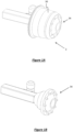
- Figure IA shows a heavy vehicle brake assembly 2, in-situ on a vehicle
- Figure IB shows the heavy vehicle brake assembly with the drum 30 having been removed.
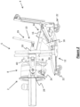
- Figure 2 shows an apparatus 4 according to a preferred embodiment of the present invention, the apparatus 4 being configured for supporting the heavy vehicle brake assembly 2 to facilitate removal and installation.
- the apparatus 4 is configured to be positionable relative to the brake assembly and movable away from the vehicle to facilitate removal of the brake assembly, and is exemplified in the Figures as a service trolley.
- the apparatus 4 has a drum and hub engagement assembly 6 configured to engage an accessible portion of an in-situ drum and hub assembly 8.
- the drum and hub engagement assembly 6 is configured to support the engaged drum and hub assembly 8 while it is being moved between an in-situ position and a removed position to facilitate removal and installation of the drum and hub assembly 8.
- the apparatus 4 also has a lifting assembly 10 for raising and lowering the drum and hub engagement assembly 6, and the drum and hub assembly 8 if so engaged, to facilitate servicing.
- the lifting assembly 10 has an upright guide assembly 12 and a lifting device 14 which is guided to raise and lower the drum and hub engagement assembly 6, and drum and/or hub assembly 8 when so engaged, for movement in a vertical line by the upright guide assembly 12.
- the drum and hub engagement assembly 6 is pivotally attached to the lifting assembly 10 which is described further in the paragraphs below.
- the apparatus 4 advantageously allows for the easy and efficient engagement and removal of the heavy brake assembly 2 without requiring heavy lifting which reduces the risk of injury and also reduces the costs and time to remove and reinstall the heavy brake assembly 2.
- the lifting device 14 includes a pair of spaced apart linked foldable support members 16 where upper and lower end portions of the foldable support members 16 are pivotally attached respectively to the drum and hub engagement assembly 6 and the base of the apparatus 4.
- the foldable support members 16 are actuated by a hydraulically powered system 18 in the form of a hydraulic cylinder positioned therebetween effecting folding and unfolding of the linked foldable supportmembers 16 to raise and lower the drum and hub engagement assembly 6 and thus the engaged drum and hub assembly 8, as illustrated in Figures 3 and 4 .
- the lifting assembly 10 has a pair of upwardly directed sleeves 20, and the guide assembly 12 is in the form of a pair of upright spaced apart shafts extending from the base of the apparatus 4.
- the upright shafts of the guide assembly are slidably received in the respective sleeves 20 allowing the drum and hub engagement assembly 6 to be guided by the guide assembly 12 in a vertical line when raised and lowered by the lifting device 14.
- Figure 2 shows the apparatus 4 positioned near the heavy vehicle brake assembly 2 and the drum and hub engagement assembly 6 which has been brought into engagement with the in-situ drum and hub assembly 8.
- the base of the apparatus 4 comprises a chassis having rollers 22 in the form of swivel castors arranged such that the apparatus 4 is positionable relative to the brake assembly 2 for engagement thereof and movable away from the vehicle to facilitate removal or replacement of the brake assembly 2.
- the lifting device 14 can be operated to raise the drum and hub assembly 8 to an appropriate level to facilitate servicing by a technician. It can be appreciated that the lifting device 14 is capable of lifting the drum and hub assembly 8 through a range of heights to allow the apparatus 4 to be used by different service technicians for different purposes.
- the drum and hub engagement assembly 6 includes a support cradle 24 for cradling the bell of the drum 30, a stud engagement member 26 for engaging the wheel studs 32 of the hub assembly 34 and a pair of spaced apart clamping members 28 for clamping the drum and hub assembly 8 to the stud engagement member 26.
- the stud engagement member 26 can be configured to engage to two or fourwheel studs 32 to engage the brake assembly 2.
- the stud engagement member 26 as exemplified in Figures 9 and 10 is in the form of a plate which has slots or apertures 27 in which the wheel studs 32 can be received.
- wheel nuts (not shown) may be applied to the wheel studs 32.
- the spaced apart clamping members 28 extend transverse from opposing sides of the stud engagement member 26 so as to receive the drum and hub assembly 8 therebetween.
- the clamping members 28 are extendable and contractable relative to the stud engagement member 26 and have inwardly directed flanges 36 at each end thereof which are configured to engage an end portion of the drum and hub assembly 8 such that the drum and hub assembly 8 is clamped between the stud engagement member 26 and flanges 36. It can be appreciated that the clamping members 28 are extendable and retractable to allow the securing of differently shaped and sized drums or drum and hub assemblies between the flanges and the stud engagement member.
- drum and hub engagement assembly 6 is to engage only the drum 30, it can be understood that the drum 30 would be engaged by the clamping members 28 such that the drum 30 is secured between the flanges 36 and stud engagement member 26.
- the hub assembly 34 may be secured to the stud engagement member 26 by wheel nuts as described above.
- the apparatus 4 can be moved away from the vehicle, as illustrated in Figures 2 and 3 .
- mechanical assistance may be required, for example in the form of a five-ton hydraulic press 29 which is integrated into the apparatus 4 as illustrated in the Figures.
- the mechanical assistance may take other forms such as pneumatic or electrically-powered systems which can be similarly integrated into the apparatus 4 or provided separately.
- the drum and hub engagement assembly 6 is pivotably attached to the lifting assembly 10, and with the drum and/or hub assembly 8 secured thereto allows inspection and replacement of bearings (not shown).
- the drum and hub engagement assembly 6 is rotatable from an operative position where the engaged drum and/or hub assembly 8 has a longitudinal axis which is generally horizontal forwards and backwards to a transverse position such that the longitudinal axis of the drum and/or hub assembly is generally vertical allowing inspection, servicing, or replacement of the bearings therein from either end.
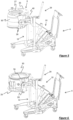
- Figure 5 illustrates that the drum and hub engagement assembly 6 and engaged drum 30 is by rotated 90° forwards such that the longitudinal axis is rotated from the operative position to the transverse position
- Figure 6 illustrates that the that the drum and hub engagement assembly 6 and engaged drum 30 is rotated 90° backwards such that the longitudinal axis is rotated from the operative position to a further transverse position. It canbe appreciated that while Figures 5 and 6 illustrate an example where only the drum 30 is engaged, the apparatus 4 can obviously be used with both the drum and hub assembly 8 engaged.
- the lifting assembly 10 has a pair of arms 38, each arm 38 being pivotally attached at one end to a clamping member 28 of the drum and hub engagement assembly 6 while the opposing end of each arm 38 is connected to the lifting device 14, as illustrated in the Figures.
- the pivotal attachment can be in the form of a friction hinge such that the drum and hub assembly 8 does not rotate unless force is applied by a service technician.
- a handle 40 as exemplified in the Figures, can be provided for ease of handling to rotate the drum and hub assembly 8.
- the handle 40 can be also be provided with a lockingmechanism (not shown) to secure the drum and hub assembly 8 in a desired orientation.
- FIGS 7 to 10 illustrates a system 42 according to an embodiment of the invention including an apparatus as described above in the form of a service trolley 44 along with a support trolley 46 which can be used to facilitate servicing and/or replacement of the hub assembly and/or drum 30.
- the support trolley 46 may be provided with a lifting device 48 such that the surface 52 of the support trolley 46 can be raised or lowered to an appropriate level to facilitate servicing by a technician.
- the lifting device 48 is exemplified in Figures 7 to 10 as a scissor lift mechanism, however it will be appreciated that other forms of lifting devices could be utilised.
- the support trolley 46 may not have a lifting device.
- the service trolley 44 has a pair of spaced apart feet 50, the support trolley 46 being receivable between the feet 50 such that the drum 30, as illustrated in Figures 7 , 8 and 10 , can be lowered by the lifting assembly 14, onto the support trolley surface 52 and disengaged from the drum and hub engagement assembly 6. Alternatively, the support trolley surface 52 can be raised to meet the drum 30. Once the previous drum 30 has been removed, the support trolley 46 with the replacement drum 54 thereon is positionable between the feet 50 of the service trolley 44 and the process reversed to engage and support the replacement drum 54 and reassemble the brake assembly 2 on the vehicle.
- each foot 50 of the service trolley 44 are provided with one of the four rollers 22 thereby ensuring that the weight of the drum and hub assembly 8 when so engaged by the service trolley 44 is stable and evenly balanced.
- trolleys 44, 46 Although only two trolleys 44, 46 are illustrated in the Figures, it can be appreciated that two or more service or support trolleys 44, 46 could be used to remove and reinstall the brake assembly 2 and to serve as work surfaces, such as during replacement of the bearings, such as illustrated in Figure 9 .
- the service trolley 44 is positioned such that the stud engagement member 26 abuts the outer end of the in-situ drum 30 and the support cradle 24 supports the weight of the drum 30. Then the clamping members 28 are engaged to the other end of the drum 30 such that the drum 30 is clamped between the flanges 36 of the clamping members 28 and stud engagement member 26 thereby securing the drum 30 to the drum and hub engagement assembly 6.
- the hub assembly 34 can be secured to the stud engagement member 26 by applying wheel nuts (not shown) to the wheel studs 32 of the hub assembly 34.
- the service trolley 44 can then be positioned to remove the drum and hub assembly 8 from the vehicle for servicing or replacement.
- the drum and hub assembly 8 can be raised or lowered by operating the lifting assembly 14 to a convenient height for inspection and/or servicing by a technician.
- the drum and hubassembly 8 can be rotated for easy access to inspect the interior thereof.
- the drum and hub assembly 8 can be engaged and removed by the service trolley 44 in a single step reducing the need to lift heavy equipment, time and costs to service the brake assembly and increasing the safety to the technicians.
- the service and support trolleys 44,46 can be positioned such that the support trolley 46 is received within the feet 50 of the service trolley 44. Then the drum and hub assembly 8 can be positioned onto the support trolley by lowering the drum and hub engagement assembly 6 or raising the support trolley surface 52, and then disengaging the drum and hub assembly 8 from the drum and hub engagement assembly 6. It can be appreciated that instead of removing the drum and hub assembly 8 together, the drum 30 can first be removed from the vehicle by the service trolley 44 and placed onto the support trolley 46 before the service trolley 44 is then used to engage and remove the hub assembly 34.
- the service and support trolleys 44, 46 can also be used to separate the hub assembly 34 from the drum 30 at a removed position from the vehicle.
- the drum and hub engagement assembly 6 can be rotated such that axis of the drum 30 is vertically oriented with the hub assembly 34 at the upper end thereof, a support block can be placed on the support trolley 46, which is positioned such that it is received within the feet 50 of the service trolley 44.
- the drum and hub assembly 8 can then be lowered onto support trolley 46 until the weight of the hub assembly 34 is supported by the support block.
- the hub assembly 34 disengages from the drum 30 while the drum 30 is still engaged by the clamping members 26.
- the drum and hub engagement assembly 6 is raised, the engaged drum 30 is also raised leaving the hub assembly 34 supported on the support trolley 46.
- the drum and hub assembly 8 can be separated in an easy and efficient way at a position removed from the vehicle, which is made possible by the ability of the service trolley 44 to raise and lower the drum and hub engagement assembly 6 in a vertical line.
- drum and hub assembly 8 Once the drum and hub assembly 8 has been inspected and serviced, they can be reassembled using a method which is generally the reverse of the disassembly procedure discussed above. It can be appreciated that the method described above is a mere example, and that the service trolley and/or support trolley 44, 46 can be used in a variety of ways to facilitate removal and servicing of the heavy brake assembly.
Landscapes
- Engineering & Computer Science (AREA)
- Mechanical Engineering (AREA)
- Transportation (AREA)
- Structural Engineering (AREA)
- General Engineering & Computer Science (AREA)
- Chemical & Material Sciences (AREA)
- Combustion & Propulsion (AREA)
- Life Sciences & Earth Sciences (AREA)
- Geology (AREA)
- Civil Engineering (AREA)
- Vehicle Cleaning, Maintenance, Repair, Refitting, And Outriggers (AREA)
- Automobile Manufacture Line, Endless Track Vehicle, Trailer (AREA)
- Braking Arrangements (AREA)
Description
- The present invention relates to an apparatus for supporting a heavy vehicle brake assembly according to the preamble of claim 1 during a servicing procedure or the like.
- Inspection, removal and servicing of a brake assembly for heavy vehicles can be difficult and time consuming due to the significant weight of the brake assembly. For example, a drum can weigh in excess of 65 kg and a hub assembly can weigh in excess of 50 kg. The general awkwardness and weight of the heavy brake assembly generally require multiple technicians working in concert to remove and reinstall the brake assembly piece by piece, a process that introduces health and safety concerns, is time-consuming, inconvenient and costly due to the manual labour required.
- An example of a prior art device
US 5,378,004 is a US patent publication document which describes a device according to the preamble of claim 1 for removing a brake drum and hub assembly having height adjustment and angle adjustment mechanisms. These adjustment mechanisms are restricted in their movement and therefore have limited usefulness for inspecting and servicing of brake drum assemblies. Another example of prior art is patent publication documentWO2017000040 which only describes a trolley removal and reassembly of calliper brake assemblies. Another prior art example is described inFR 2988358 - According to a first aspect of the present invention, there is provided an apparatus for supporting a heavy vehicle brake assembly, the apparatus configured to engage and support the brake assembly to facilitate removal and installation, the apparatus comprising:
- a drum and hub engagement assembly configured to engage an accessible portion of an in-situ drum and/or hub assembly and to support the drum and/or hub assembly when so engaged for transport between an in-situ position and a removed position facilitating removal and installation of the drum and/or hub assembly;
- wherein the apparatus is configured to be positionable relative to the brake assembly and movable away from the vehicle to facilitate removal of the brake assembly
- the apparatus further including a lifting assembly having an upright guide assembly and a lifting device for raising and lowering the drum and hub engagement assembly, wherein the lifting device is configured to raise and lower the drum and hub engagement assembly and the drum and/orhub assembly engaged thereby along the upright guide assembly in a vertical line to facilitate servicing; and
- characterized in that the drum and hub engagement assembly, and the drum and/or hub assembly when so engaged, is configured to be rotatable about an axis which substantially passes through a centre of mass of the drum to facilitate servicing.
- The drum and hub engagement assembly, and the drum and/or hub assembly when so engaged, can be rotatable from an operative position where the engaged drum and/or hub assembly has a longitudinal axis which is generally horizontal for removal and installation thereof to a transverse position wherein the axis is generally vertical.The drum and hub assembly may be rotatable into the transverse position such that the opening of the drum is orientated substantially upwardly so as to facilitate easy access to inspect the interior of the drum. The apparatus can include a friction hinge for preventing rotation of the drum and hub engagement assembly unless force is applied by a user of the apparatus. The apparatus can include a locking mechanism for securing rotation of the drum and hub engagement assembly in a desired orientation.
- There exists also an apparatus for supporting a heavy vehicle brake assembly, configured to engage and support the brake assembly to facilitate removal and installation, the apparatus comprising:
- a drum and hub engagement assembly configured to engage an accessible portion of an in-situ drum and/or hub assembly and to support the drum and/or hub assembly when so engaged for transport between an in-situ position and a removed position facilitating removal and installation of the drum and/or hub assembly, and
- wherein the apparatus is configured to be positionable relative to the brake assembly and movable away from the vehicle to facilitate removal of the brake assembly, and wherein, when the brake assembly is so removed, the drum and hub engagement assembly, and the drum and/or hub assembly when so engaged, is configured to be rotatable to facilitate servicing.
- According to an embodiment, the drum and hub engagement assembly, and the drum and/or hub assembly when so engaged, is rotatable from an operative position where the engaged drum and/or hub assembly has a longitudinal axis which is generally horizontal for removal and installation thereof to a transverse position wherein the axis is generally vertical.
- According to an embodiment, the drum and hub engagement assembly, and the drum and/or hub assembly when so engaged, is rotatable from the operative position to the transverse position in either a clockwise or an anti-clockwise direction.
- According to an embodiment, the lifting device comprises at least one linked foldable support member configured to be driven for movement in the vertical plane, an upper end of the support member(s) associated with the drum and hub engagement assembly and wherein the foldable support member(s) are extendable and retractable relative to the trolley to raise and lower the drum and hub engagement assembly in a vertical line guided by the upright guide assembly.
- According to an embodiment, the drum and hub engagement assembly has a stud engagement member for engaging the hub assembly and a drum engagement assembly.
- According to an embodiment, the trolley also has means for removing the hub assembly or drum and hub assembly from an axle from a vehicle.
- According to an embodiment, the trolley has a pair of spaced apart feet configured to receive a further trolley therebetween.
- According to a third aspect of the present invention, there is provided a system for removing and reinstalling a heavy vehicle brake assembly having a first trolley as described above, and a second trolley having a surface for assisting in replacement and/or servicing wherein the first trolley has a pair of spaced-apart feet configured to receive the second trolley therebetween.
- According to an embodiment, the second trolley has means for raising and lowering the surface thereof.
- According to an embodiment, the second trolley is configured to be positionable to be received between the feet of the first trolley and movable away from the first trolley to facilitate servicing and replacement.
- According to a fourth aspect of the present invention, there is provided a method of removing a heavy vehicle brake assembly from a vehicle using the system as described above, comprising the steps of:
- engaging the in-situ drum or hub assembly with the drum and hub engagement assembly of the first trolley;
- removing the drum or hub assembly from the vehicle; and
- lifting or rotating the drum and hub engagement assembly to facilitate servicing.
- According to an embodiment, the method further comprises the steps of:
- positioning the second trolley such that it is received within the feet of the first trolley;
- lowering the drum and hub engagement assembly and/or raising the second trolley surface such that the drum and/or hub assembly is received on the second trolley surface; and
- disengaging the drum or hub assembly from the drum and hub engagement assembly.
- According to an embodiment, the drum and hub assembly are removed together.
- According to an embodiment, the method further comprises the steps of:
- rotating the drum and hub engagement assembly such that the drum and hub assembly is oriented so that the hub is at the upper end of the drum and hub assembly;
- lowering the drum and hub engagement assembly and/or raising the second trolley surface such that the hub assembly is supported on the second trolley surface;
- disengaging the hub from the drum and hub engagement assembly; and
- raising the drum and hub engagement assembly with the engaged drum such that the hub assembly is separated from the drum.
- Further aspects, features, implementations and advantages of the present invention may be appreciated from the following description of one or more embodiments thereof, presented by way of non-limiting example only and with reference to the accompanying drawings in which:
-
Figure 1A is a perspective view of a heavy vehicle brake assembly; -
Figure 1B is a perspective view of the heavy vehicle brake assembly with the drum removed; -
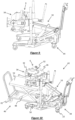
Figure 2 is a perspective view of the brake assembly and an apparatus engaging the brake assembly according to an embodiment of the present invention; -
Figure 3 is a perspective view of the apparatus positioned away from the vehicle with the brake assembly attached thereto; -
Figure 4 is a perspective view of the apparatus in a raised configuration showing the brake assembly lifted in a position for service; -
Figure 5 is a perspective view of the apparatus with the brake assembly rotated into a first position for service; -
Figure 6 is a perspective view of the apparatus with the brake assembly rotated into a second position for service; -
Figure 7 is a perspective view of a system including a support trolley where the brake assembly is lowered onto the support trolley according to another embodiment of the present invention; -
Figure 8 is a perspective view of the system ofFigure 7 showing a new brake assembly on the support trolley ready for installation; -
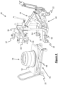
Figures 9 and 10 are perspective views of the system in use, in particularFigure 9 is a view showing the apparatus supporting a hub assembly after it has been removed from the vehicle and Figure I O is a view showing the support trolley positioned to provide a work surface for servicing the hub assembly. - Figure IA shows a heavy
vehicle brake assembly 2, in-situ on a vehicle, while Figure IB shows the heavy vehicle brake assembly with thedrum 30 having been removed.Figure 2 shows anapparatus 4 according to a preferred embodiment of the present invention, theapparatus 4 being configured for supporting the heavyvehicle brake assembly 2 to facilitate removal and installation. Theapparatus 4 is configured to be positionable relative to the brake assembly and movable away from the vehicle to facilitate removal of the brake assembly, and is exemplified in the Figures as a service trolley. - The
apparatus 4 has a drum andhub engagement assembly 6 configured to engage an accessible portion of an in-situ drum andhub assembly 8. The drum andhub engagement assembly 6 is configured to support the engaged drum andhub assembly 8 while it is being moved between an in-situ position and a removed position to facilitate removal and installation of the drum andhub assembly 8. - The
apparatus 4 also has alifting assembly 10 for raising and lowering the drum andhub engagement assembly 6, and the drum andhub assembly 8 if so engaged, to facilitate servicing. In the embodiment illustrated in the Figures, thelifting assembly 10 has anupright guide assembly 12 and alifting device 14 which is guided to raise and lower the drum andhub engagement assembly 6, and drum and/orhub assembly 8 when so engaged, for movement in a vertical line by theupright guide assembly 12. The drum andhub engagement assembly 6 is pivotally attached to thelifting assembly 10 which is described further in the paragraphs below. - Thus the
apparatus 4 advantageously allows for the easy and efficient engagement and removal of theheavy brake assembly 2 without requiring heavy lifting which reduces the risk of injury and also reduces the costs and time to remove and reinstall theheavy brake assembly 2. - As illustrated in
Figures 2 to 6 , thelifting device 14 includes a pair of spaced apart linkedfoldable support members 16 where upper and lower end portions of thefoldable support members 16 are pivotally attached respectively to the drum andhub engagement assembly 6 and the base of theapparatus 4. Thefoldable support members 16 are actuated by a hydraulically poweredsystem 18 in the form of a hydraulic cylinder positioned therebetween effecting folding and unfolding of the linkedfoldable supportmembers 16 to raise and lower the drum andhub engagement assembly 6 and thus the engaged drum andhub assembly 8, as illustrated inFigures 3 and 4 . - In the examples shown in the Figures, the
lifting assembly 10 has a pair of upwardly directedsleeves 20, and theguide assembly 12 is in the form of a pair of upright spaced apart shafts extending from the base of theapparatus 4. The upright shafts of the guide assembly are slidably received in therespective sleeves 20 allowing the drum andhub engagement assembly 6 to be guided by theguide assembly 12 in a vertical line when raised and lowered by the liftingdevice 14. -
Figure 2 shows theapparatus 4 positioned near the heavyvehicle brake assembly 2 and the drum andhub engagement assembly 6 which has been brought into engagement with the in-situ drum andhub assembly 8. The base of theapparatus 4 comprises achassis having rollers 22 in the form of swivel castors arranged such that theapparatus 4 is positionable relative to thebrake assembly 2 for engagement thereof and movable away from the vehicle to facilitate removal or replacement of thebrake assembly 2. - In the example shown in
Figures 3 and 4 , once thebrake assembly 2 has been removed from the vehicle, the liftingdevice 14 can be operated to raise the drum andhub assembly 8 to an appropriate level to facilitate servicing by a technician. It can be appreciated that thelifting device 14 is capable of lifting the drum andhub assembly 8 through a range of heights to allow theapparatus 4 to be used by different service technicians for different purposes. - As illustrated in
Figures 2 to 6 , the drum andhub engagement assembly 6 includes asupport cradle 24 for cradling the bell of thedrum 30, astud engagement member 26 for engaging thewheel studs 32 of thehub assembly 34 and a pair of spaced apart clampingmembers 28 for clamping the drum andhub assembly 8 to thestud engagement member 26. Thestud engagement member 26 can be configured to engage to two orfourwheel studs 32 to engage thebrake assembly 2. Thestud engagement member 26 as exemplified inFigures 9 and 10 is in the form of a plate which has slots orapertures 27 in which thewheel studs 32 can be received. To secure thehub assembly 34 to theengagement member 26, wheel nuts (not shown) may be applied to thewheel studs 32. - The spaced apart clamping
members 28 extend transverse from opposing sides of thestud engagement member 26 so as to receive the drum andhub assembly 8 therebetween. The clampingmembers 28 are extendable and contractable relative to thestud engagement member 26 and have inwardly directedflanges 36 at each end thereof which are configured to engage an end portion of the drum andhub assembly 8 such that the drum andhub assembly 8 is clamped between thestud engagement member 26 andflanges 36. It can be appreciated that the clampingmembers 28 are extendable and retractable to allow the securing of differently shaped and sized drums or drum and hub assemblies between the flanges and the stud engagement member. - If the drum and
hub engagement assembly 6 is to engage only thedrum 30, it can be understood that thedrum 30 would be engaged by the clampingmembers 28 such that thedrum 30 is secured between theflanges 36 andstud engagement member 26. Alternatively, if only thehub assembly 34 is engaged by the drum andhub engagement assembly 6, thehub assembly 34 may be secured to thestud engagement member 26 by wheel nuts as described above. - Once the
brake assembly 2 is brought into engagement with the drum andhub engagement assembly 6, theapparatus 4 can be moved away from the vehicle, as illustrated inFigures 2 and3 . To remove thebrake assembly 2 from the vehicle, mechanical assistance may be required, for example in the form of a five-tonhydraulic press 29 which is integrated into theapparatus 4 as illustrated in the Figures. However it can be appreciated that the mechanical assistance may take other forms such as pneumatic or electrically-powered systems which can be similarly integrated into theapparatus 4 or provided separately. - The drum and
hub engagement assembly 6 is pivotably attached to the liftingassembly 10, and with the drum and/orhub assembly 8 secured thereto allows inspection and replacement of bearings (not shown). The drum andhub engagement assembly 6 is rotatable from an operative position where the engaged drum and/orhub assembly 8 has a longitudinal axis which is generally horizontal forwards and backwards to a transverse position such that the longitudinal axis of the drum and/or hub assembly is generally vertical allowing inspection, servicing, or replacement of the bearings therein from either end. -
Figure 5 illustrates that the drum andhub engagement assembly 6 and engageddrum 30 is by rotated 90° forwards such that the longitudinal axis is rotated from the operative position to the transverse position, whileFigure 6 illustrates that the that the drum andhub engagement assembly 6 and engageddrum 30 is rotated 90° backwards such that the longitudinal axis is rotated from the operative position to a further transverse position. It canbe appreciated that whileFigures 5 and 6 illustrate an example where only thedrum 30 is engaged, theapparatus 4 can obviously be used with both the drum andhub assembly 8 engaged. - Alternatively, as illustrated in
Figures 9 and 10 , only the in-situ hub assembly 34 may be engaged to thestud engagement member 26 and removed from the vehicle, and thus thestud engagement member 26 with thehub assembly 34 so engaged can be raised or lowered or rotated in a similar manner as described above for servicing. - The lifting
assembly 10 has a pair ofarms 38, eacharm 38 being pivotally attached at one end to a clampingmember 28 of the drum andhub engagement assembly 6 while the opposing end of eacharm 38 is connected to thelifting device 14, as illustrated in the Figures. In addition, the pivotal attachment can be in the form of a friction hinge such that the drum andhub assembly 8 does not rotate unless force is applied by a service technician. Ahandle 40, as exemplified in the Figures, can be provided for ease of handling to rotate the drum andhub assembly 8. Thehandle 40 can be also be provided with a lockingmechanism (not shown) to secure the drum andhub assembly 8 in a desired orientation. -
Figures 7 to 10 illustrates asystem 42 according to an embodiment of the invention including an apparatus as described above in the form of aservice trolley 44 along with asupport trolley 46 which can be used to facilitate servicing and/or replacement of the hub assembly and/ordrum 30. Thesupport trolley 46 may be provided with alifting device 48 such that thesurface 52 of thesupport trolley 46 can be raised or lowered to an appropriate level to facilitate servicing by a technician. The liftingdevice 48 is exemplified inFigures 7 to 10 as a scissor lift mechanism, however it will be appreciated that other forms of lifting devices could be utilised. Alternatively, thesupport trolley 46 may not have a lifting device. - The
service trolley 44 has a pair of spacedapart feet 50, thesupport trolley 46 being receivable between thefeet 50 such that thedrum 30, as illustrated inFigures 7 ,8 and10 , can be lowered by the liftingassembly 14, onto thesupport trolley surface 52 and disengaged from the drum andhub engagement assembly 6. Alternatively, thesupport trolley surface 52 can be raised to meet thedrum 30. Once theprevious drum 30 has been removed, thesupport trolley 46 with thereplacement drum 54 thereon is positionable between thefeet 50 of theservice trolley 44 and the process reversed to engage and support thereplacement drum 54 and reassemble thebrake assembly 2 on the vehicle. - End portions of each
foot 50 of theservice trolley 44 are provided with one of the fourrollers 22 thereby ensuring that the weight of the drum andhub assembly 8 when so engaged by theservice trolley 44 is stable and evenly balanced. - Although only two
trolleys support trolleys brake assembly 2 and to serve as work surfaces, such as during replacement of the bearings, such as illustrated inFigure 9 . - In an example method of use of the
system 42, theservice trolley 44 is positioned such that thestud engagement member 26 abuts the outer end of the in-situ drum 30 and thesupport cradle 24 supports the weight of thedrum 30. Then the clampingmembers 28 are engaged to the other end of thedrum 30 such that thedrum 30 is clamped between theflanges 36 of the clampingmembers 28 andstud engagement member 26 thereby securing thedrum 30 to the drum andhub engagement assembly 6. Thehub assembly 34 can be secured to thestud engagement member 26 by applying wheel nuts (not shown) to thewheel studs 32 of thehub assembly 34. - The
service trolley 44 can then be positioned to remove the drum andhub assembly 8 from the vehicle for servicing or replacement. In particular, the drum andhub assembly 8 can be raised or lowered by operating the liftingassembly 14 to a convenient height for inspection and/or servicing by a technician. Furthermore, the drum andhubassembly 8 can be rotated for easy access to inspect the interior thereof. Thus advantageously the drum andhub assembly 8 can be engaged and removed by theservice trolley 44 in a single step reducing the need to lift heavy equipment, time and costs to service the brake assembly and increasing the safety to the technicians. - If replacing the drum and
hub assembly 8, the service andsupport trolleys support trolley 46 is received within thefeet 50 of theservice trolley 44. Then the drum andhub assembly 8 can be positioned onto the support trolley by lowering the drum andhub engagement assembly 6 or raising thesupport trolley surface 52, and then disengaging the drum andhub assembly 8 from the drum andhub engagement assembly 6. It can be appreciated that instead of removing the drum andhub assembly 8 together, thedrum 30 can first be removed from the vehicle by theservice trolley 44 and placed onto thesupport trolley 46 before theservice trolley 44 is then used to engage and remove thehub assembly 34. - In another example use of the system, the service and
support trolleys hub assembly 34 from thedrum 30 at a removed position from the vehicle. First, the drum andhub engagement assembly 6 can be rotated such that axis of thedrum 30 is vertically oriented with thehub assembly 34 at the upper end thereof, a support block can be placed on thesupport trolley 46, which is positioned such that it is received within thefeet 50 of theservice trolley 44. The drum andhub assembly 8 can then be lowered ontosupport trolley 46 until the weight of thehub assembly 34 is supported by the support block. - By removing the wheel nuts (not shown) attaching the
hub assembly 34 to thestud engagement member 26 thehub assembly 34 disengages from thedrum 30 while thedrum 30 is still engaged by the clampingmembers 26. When the drum andhub engagement assembly 6 is raised, the engageddrum 30 is also raised leaving thehub assembly 34 supported on thesupport trolley 46. Thus the drum andhub assembly 8 can be separated in an easy and efficient way at a position removed from the vehicle, which is made possible by the ability of theservice trolley 44 to raise and lower the drum andhub engagement assembly 6 in a vertical line. - Once the drum and
hub assembly 8 has been inspected and serviced, they can be reassembled using a method which is generally the reverse of the disassembly procedure discussed above. It can be appreciated that the method described above is a mere example, and that the service trolley and/orsupport trolley - While various embodiments of the present invention have been described above, it should be understood that they have been presented by way of example only, and not by way of limitation. Thus, the present invention should not be limited by any of the above described exemplary embodiments.
- Throughout this specification and the claims which follow, unless the context requires otherwise, the word "comprise", and variations such as "comprises" and "comprising", will be understood to imply the inclusion of a stated integer or step or group of integers or steps but not the exclusion of any other integer or step or group of integers or steps.
Claims (15)
- An apparatus (4) for supporting a drum and hub assembly (8) of a heavy vehicle brake assembly, the apparatus (4) configured to engage and support the drum and hub assembly (8) to facilitate removal and installation, the apparatus (40 comprising:a drum and hub engagement assembly (6) configured to engage an accessible portion of the in-situ drum and/or hub assembly (8) and to support the drum and/or hub assembly (8) when so engaged for transport between an in-situ position and a removed position facilitating removal and installation of the drum and/or hub assembly (8);wherein the apparatus (4) is configured to be positionable relative to the brake assembly (2) and movable away from the vehicle to facilitate removal of the brake assembly (2);the apparatus (4) further including a lifting assembly (10) having an upright guide assembly (12) and a lifting device (14) for raising and lowering the drum and hub engagement assembly (6), wherein the lifting device (14) is configured to raise and lower the drum and hub engagement assembly (6) and the drum and/or hub assembly (8) engaged thereby along the upright guide assembly (12) in a vertical line;
characterized in that the drum and hub engagement assembly (6), and the drum and/or hub assembly (8) when so engaged, is configured to be rotatable about an axis which substantially passes through a centre of mass of the drum to facilitate servicing of the drum and/or hub assembly (8). - An apparatus (4) according to claim 1, wherein the drum and hub engagement assembly (6), and the drum and/or hub assembly (8) when so engaged, is rotatable from an operative position where the engaged drum and/or hub assembly (8) has a longitudinal axis which is generally horizontal for removal and installation thereof to a transverse position wherein the axis is generally vertical.
- An apparatus (4) according to claim 1 or claim 2, wherein the drum and hub engagement assembly (6), and the drum and/or hub assembly (8) when so engaged, is rotatable from the operative position to the transverse position in either a clockwise or an anti-clockwise direction.
- An apparatus (4) according to any one of claims 1 to 3, wherein the drum and hub assembly (8) is rotatable into the transverse position such that the opening of the drum (30) is orientated substantially upwardly so as to facilitate easy access to inspect the interior of the drum (30).
- An apparatus (4) according to any one of claims 1 to 4, wherein the apparatus (4) includes a friction hinge for preventing rotation of the drum and hub engagement assembly (6) unless force is applied by a user of the apparatus (4).
- An apparatus (4) according to any one of claims 1 to 5, wherein the apparatus (4) includes a locking mechanism for securing rotation of the drum and hub engagement assembly (6) in a desired orientation.
- An apparatus (4) according to any one of claims 1 to 6, wherein the lifting device (14) comprises at least one linked foldable support member (16) configured to be driven for movement in the vertical plane, an upper end of the support member(s) (16) associated with the drum and hub engagement assembly (6) and wherein the foldable support member(s) are extendable and retractable relative to the apparatus (4) to raise and lower the drum and hub engagement assembly (6) in a vertical line guided by the upright guide assembly (12).
- An apparatus (4) according to any one of the preceding claims, wherein the drum and hub engagement assembly (6) has a stud engagement member (26) for engaging the hub assembly and a drum engagement assembly.
- An apparatus (4) according to any one of the preceding claims, further having means for removing the drum and hub assembly (8) from an axle from a vehicle.
- An apparatus (4) according to any one of the preceding claims, having a pair of spaced apart feet configured to receive a trolley (46) therebetween.
- A system (42) for removing and reinstalling a heavy vehicle brake assembly having an apparatus according to any one of claims 1 to 8, and a trolley (46) having a surface (52) for assisting in replacement and/or servicing wherein the apparatus (4) has a pair of spaced-apart feet (50) configured to receive the trolley (46) therebetween.
- A system (42) according to claim 11, wherein, the trolley (46) has means for raising and lowering the surface (52) thereof, and optionally wherein the trolley (46) is configured to be positionable to be received between the feet (50) of the apparatus (4) and movable away from the apparatus (4) to facilitate servicing and replacement.
- A method of removing a heavy vehicle brake assembly (2) comprising a drum and hub assembly (8) from a vehicle using the system (42) of claims 11 or 12 comprising the steps of:engaging the in-situ drum or hub assembly with the drum and hub engagement assembly (6) of the apparatus (4);removing the drum or hub assembly from the vehicle;lifting or rotating the drum and hub engagement assembly (6) to facilitate servicing.
- A method according to claim 13, comprising the steps of:positioning the trolley (46) such that it is received within the feet (50) of the apparatus (4);lowering the drum and hub engagement assembly (6) and/or raising the trolley surface (52) such that the drum and/or hub assembly (8) is received on the trolley surface (52); anddisengaging the drum or hub assembly from the drum and hub engagement assembly (6), andoptionally wherein the drum and hub assembly (8) are removed together.
- A method according to claim 14, comprising the steps of:rotating the drum and hub engagement assembly (6) such that the drum and hub assembly (8) is oriented so that the hub is at the upper end of the drum and hub assembly (6);lowering the drum and hub engagement assembly (8) and/or raising the trolley surface (52) such that the hub assembly (34) is supported on the trolley surface (52);disengaging the hub from the drum and hub engagement assembly (6); andraising the drum and hub engagement assembly (6) with the engaged drum (30) such that the hub assembly (34) is separated from the drum (30).
Applications Claiming Priority (2)
| Application Number | Priority Date | Filing Date | Title |
|---|---|---|---|
| AU2017902517A AU2017902517A0 (en) | 2017-06-29 | An apparatus for supporting a heavy brake assembly | |
| PCT/AU2018/050679 WO2019000053A1 (en) | 2017-06-29 | 2018-06-29 | An apparatus for supporting a heavy vehicle brake assembly |
Publications (3)
| Publication Number | Publication Date |
|---|---|
| EP3645212A1 EP3645212A1 (en) | 2020-05-06 |
| EP3645212A4 EP3645212A4 (en) | 2021-08-25 |
| EP3645212B1 true EP3645212B1 (en) | 2024-11-06 |
Family
ID=64740198
Family Applications (1)
| Application Number | Title | Priority Date | Filing Date |
|---|---|---|---|
| EP18822869.6A Active EP3645212B1 (en) | 2017-06-29 | 2018-06-29 | An apparatus for supporting a heavy vehicle brake assembly |
Country Status (5)
| Country | Link |
|---|---|
| US (1) | US12071991B2 (en) |
| EP (1) | EP3645212B1 (en) |
| AU (1) | AU2018293933B2 (en) |
| CA (1) | CA3067672A1 (en) |
| WO (1) | WO2019000053A1 (en) |
Families Citing this family (7)
| Publication number | Priority date | Publication date | Assignee | Title |
|---|---|---|---|---|
| EP3645212B1 (en) | 2017-06-29 | 2024-11-06 | WORKPLACE MAINTENANCE SOLUTIONS Pty Ltd | An apparatus for supporting a heavy vehicle brake assembly |
| US11059409B2 (en) * | 2018-12-17 | 2021-07-13 | Data Shredding Services of Texas, Inc. | Methods and systems associated with a mobile bin tipper |
| CN111497974A (en) * | 2020-05-26 | 2020-08-07 | 浙江盘毂动力科技有限公司 | An independent suspension vehicle installation tool |
| US20240401655A1 (en) * | 2020-06-11 | 2024-12-05 | Workplace Maintenance Solutions Pty Ltd | Apparatus for facilitating servicing of vehicle brake assemblies |
| CN111746615A (en) * | 2020-06-24 | 2020-10-09 | 广东电网有限责任公司 | A cable tray handling trolley |
| CN112477955A (en) * | 2020-11-23 | 2021-03-12 | 重庆铁马工业集团有限公司 | Armored vehicle wheel edge transfer device and transfer method thereof |
| FR3124151B1 (en) * | 2021-06-22 | 2023-06-30 | Safran Aircraft Engines | Workshop trolley for turbomachine stator or rotor element |
Citations (1)
| Publication number | Priority date | Publication date | Assignee | Title |
|---|---|---|---|---|
| CA2117208C (en) * | 1994-03-08 | 2000-06-06 | Danny E. Gunlock | Device for removing brake drum and hub assembly |
Family Cites Families (20)
| Publication number | Priority date | Publication date | Assignee | Title |
|---|---|---|---|---|
| US5127638A (en) * | 1991-03-11 | 1992-07-07 | Kent Cloyce G | Apparatus for removing wheel hubs from vehicle axles |
| US5378004A (en) * | 1993-02-01 | 1995-01-03 | The Prodx Company | Device for removing brake drum and hub assembly |
| US5895030A (en) * | 1997-06-13 | 1999-04-20 | Mohun; George E. | Heavy duty device for use in removing and servicing wheel drum and hub assemblies |
| US6237206B1 (en) * | 1998-03-12 | 2001-05-29 | Kiene Diesel Accessories, Inc. | Wheel pulling and transporting device |
| US6382644B1 (en) * | 1999-11-05 | 2002-05-07 | Safe Tools Shop, Inc. | Apparatus for transporting and positioning tire and wheel assemblies |
| US20050081355A1 (en) * | 2003-10-16 | 2005-04-21 | Nechvatal Robert J. | Air disc brake caliper jack assembly |
| US20050254923A1 (en) * | 2004-05-13 | 2005-11-17 | Spx Corporation | High lift wheel dolly method and apparatus |
| US7918637B2 (en) * | 2007-05-25 | 2011-04-05 | Toyota Motor Engineering & Manufacturing North America, Inc. | Assist device for a tire and wheel assembly |
| US7766306B2 (en) * | 2007-12-21 | 2010-08-03 | Morey Robert P | Device for removing wheel end components as an assembly on vehicles with ball joints and method for servicing vehicle ball joints |
| FR2956851B1 (en) * | 2010-03-01 | 2014-05-09 | A C E Ingenierie | HANDLING DEVICE FOR THE HANDLING OF HEAVY OBJECTS |
| FR2988358B1 (en) | 2012-03-20 | 2014-04-18 | Peugeot Citroen Automobiles Sa | ASSISTING DEVICE FOR ASSEMBLING A WHEEL ASSEMBLY ON A RUNNING TRAIN TRAIN OF A MOTOR VEHICLE |
| SE536555C2 (en) * | 2012-06-20 | 2014-02-18 | Scania Cv Ab | Device for mounting and disassembly of caliper and method for mounting and disassembling such caliper |
| DE102012106073A1 (en) * | 2012-07-06 | 2014-01-09 | Gerhard Finkbeiner | Lifting device and method for mounting and dismounting a wheel with such a lifting device |
| US9771990B2 (en) * | 2014-06-18 | 2017-09-26 | Prowse Holdings Pty Ltd | Brake component handling apparatus |
| WO2017000040A1 (en) * | 2015-06-30 | 2017-01-05 | Truck & Bus Technology Pty Ltd | Trolley for supporting a heavy vehicle brake assembly |
| US10427652B2 (en) * | 2016-11-04 | 2019-10-01 | Stemco Products, Inc. | Steering axle kingpin removal system |
| US20180126962A1 (en) * | 2016-11-04 | 2018-05-10 | Stemco Products, Inc. | Steering axle kingpin removal system |
| EP3645212B1 (en) * | 2017-06-29 | 2024-11-06 | WORKPLACE MAINTENANCE SOLUTIONS Pty Ltd | An apparatus for supporting a heavy vehicle brake assembly |
| US20200269641A1 (en) * | 2019-02-22 | 2020-08-27 | Kenneth Lee Edwards, SR. | Mechanical Tire Lift |
| US11267087B2 (en) * | 2019-12-17 | 2022-03-08 | Saudi Arabian Oil Company | Rotating machine coupling hub pulling device |
-
2018
- 2018-06-29 EP EP18822869.6A patent/EP3645212B1/en active Active
- 2018-06-29 CA CA3067672A patent/CA3067672A1/en active Pending
- 2018-06-29 US US16/626,063 patent/US12071991B2/en active Active
- 2018-06-29 WO PCT/AU2018/050679 patent/WO2019000053A1/en not_active Ceased
- 2018-06-29 AU AU2018293933A patent/AU2018293933B2/en active Active
Patent Citations (1)
| Publication number | Priority date | Publication date | Assignee | Title |
|---|---|---|---|---|
| CA2117208C (en) * | 1994-03-08 | 2000-06-06 | Danny E. Gunlock | Device for removing brake drum and hub assembly |
Also Published As
| Publication number | Publication date |
|---|---|
| AU2018293933B2 (en) | 2025-01-23 |
| AU2018293933A1 (en) | 2020-02-13 |
| US12071991B2 (en) | 2024-08-27 |
| CA3067672A1 (en) | 2019-01-03 |
| WO2019000053A1 (en) | 2019-01-03 |
| US20200217376A1 (en) | 2020-07-09 |
| EP3645212A1 (en) | 2020-05-06 |
| EP3645212A4 (en) | 2021-08-25 |
Similar Documents
| Publication | Publication Date | Title |
|---|---|---|
| US12071991B2 (en) | Apparatus for supporting a heavy vehicle brake assembly | |
| US3830387A (en) | Vehicle wheel handling apparatus | |
| EP3707009B1 (en) | A rack and apparatus for supporting wheels | |
| US5269501A (en) | Vehicle and vehicle parts transportation system | |
| US5340082A (en) | Portable surface lift for a vehicle | |
| US4771531A (en) | Device for lifting vehicle wheels | |
| US10933692B1 (en) | Wheel righting apparatus | |
| CN113524990B (en) | Electric tyre dismounting device for airplane | |
| US5181821A (en) | Brake drum support apparatus | |
| CA2424804C (en) | A method of and apparatus for assembling an aircraft wheel or brake component on an axle of an undercarriage | |
| JPH092008A (en) | Wheel dolly | |
| US20240401655A1 (en) | Apparatus for facilitating servicing of vehicle brake assemblies | |
| EP0052586A2 (en) | Device for facilitating the mounting and dismounting of large vehicle wheels | |
| AU2016285881B2 (en) | Trolley for supporting a heavy vehicle brake assembly | |
| US7942620B2 (en) | Tire handling apparatus | |
| WO2015029017A1 (en) | Solid tire press | |
| CN117774572A (en) | Heavy-duty tire stripper and its use | |
| US12012319B2 (en) | Tire and wheel lift assistance assembly and method | |
| CA2527552C (en) | Tire handling apparatus | |
| AU2023200205A1 (en) | Roller bearing support apparatus | |
| JPH04121980U (en) | Lifting equipment for roll handling |
Legal Events
| Date | Code | Title | Description |
|---|---|---|---|
| STAA | Information on the status of an ep patent application or granted ep patent |
Free format text: STATUS: THE INTERNATIONAL PUBLICATION HAS BEEN MADE |
|
| PUAI | Public reference made under article 153(3) epc to a published international application that has entered the european phase |
Free format text: ORIGINAL CODE: 0009012 |
|
| STAA | Information on the status of an ep patent application or granted ep patent |
Free format text: STATUS: REQUEST FOR EXAMINATION WAS MADE |
|
| 17P | Request for examination filed |
Effective date: 20200127 |
|
| AK | Designated contracting states |
Kind code of ref document: A1 Designated state(s): AL AT BE BG CH CY CZ DE DK EE ES FI FR GB GR HR HU IE IS IT LI LT LU LV MC MK MT NL NO PL PT RO RS SE SI SK SM TR |
|
| AX | Request for extension of the european patent |
Extension state: BA ME |
|
| DAV | Request for validation of the european patent (deleted) | ||
| DAX | Request for extension of the european patent (deleted) | ||
| A4 | Supplementary search report drawn up and despatched |
Effective date: 20210726 |
|
| RIC1 | Information provided on ipc code assigned before grant |
Ipc: B25B 11/02 20060101AFI20210720BHEP Ipc: F16D 65/00 20060101ALI20210720BHEP Ipc: B62B 3/04 20060101ALI20210720BHEP Ipc: B66F 9/06 20060101ALI20210720BHEP Ipc: B25B 27/00 20060101ALI20210720BHEP Ipc: B25B 27/06 20060101ALI20210720BHEP |
|
| STAA | Information on the status of an ep patent application or granted ep patent |
Free format text: STATUS: EXAMINATION IS IN PROGRESS |
|
| 17Q | First examination report despatched |
Effective date: 20230223 |
|
| GRAP | Despatch of communication of intention to grant a patent |
Free format text: ORIGINAL CODE: EPIDOSNIGR1 |
|
| STAA | Information on the status of an ep patent application or granted ep patent |
Free format text: STATUS: GRANT OF PATENT IS INTENDED |
|
| INTG | Intention to grant announced |
Effective date: 20240531 |
|
| GRAS | Grant fee paid |
Free format text: ORIGINAL CODE: EPIDOSNIGR3 |
|
| GRAA | (expected) grant |
Free format text: ORIGINAL CODE: 0009210 |
|
| STAA | Information on the status of an ep patent application or granted ep patent |
Free format text: STATUS: THE PATENT HAS BEEN GRANTED |
|
| AK | Designated contracting states |
Kind code of ref document: B1 Designated state(s): AL AT BE BG CH CY CZ DE DK EE ES FI FR GB GR HR HU IE IS IT LI LT LU LV MC MK MT NL NO PL PT RO RS SE SI SK SM TR |
|
| REG | Reference to a national code |
Ref country code: GB Ref legal event code: FG4D |
|
| REG | Reference to a national code |
Ref country code: CH Ref legal event code: EP |
|
| REG | Reference to a national code |
Ref country code: DE Ref legal event code: R096 Ref document number: 602018076334 Country of ref document: DE |
|
| REG | Reference to a national code |
Ref country code: IE Ref legal event code: FG4D |
|
| REG | Reference to a national code |
Ref country code: LT Ref legal event code: MG9D |
|
| REG | Reference to a national code |
Ref country code: NL Ref legal event code: MP Effective date: 20241106 |
|
| PG25 | Lapsed in a contracting state [announced via postgrant information from national office to epo] |
Ref country code: PT Free format text: LAPSE BECAUSE OF FAILURE TO SUBMIT A TRANSLATION OF THE DESCRIPTION OR TO PAY THE FEE WITHIN THE PRESCRIBED TIME-LIMIT Effective date: 20250306 Ref country code: HR Free format text: LAPSE BECAUSE OF FAILURE TO SUBMIT A TRANSLATION OF THE DESCRIPTION OR TO PAY THE FEE WITHIN THE PRESCRIBED TIME-LIMIT Effective date: 20241106 Ref country code: IS Free format text: LAPSE BECAUSE OF FAILURE TO SUBMIT A TRANSLATION OF THE DESCRIPTION OR TO PAY THE FEE WITHIN THE PRESCRIBED TIME-LIMIT Effective date: 20250306 |
|
| PG25 | Lapsed in a contracting state [announced via postgrant information from national office to epo] |
Ref country code: FI Free format text: LAPSE BECAUSE OF FAILURE TO SUBMIT A TRANSLATION OF THE DESCRIPTION OR TO PAY THE FEE WITHIN THE PRESCRIBED TIME-LIMIT Effective date: 20241106 Ref country code: NL Free format text: LAPSE BECAUSE OF FAILURE TO SUBMIT A TRANSLATION OF THE DESCRIPTION OR TO PAY THE FEE WITHIN THE PRESCRIBED TIME-LIMIT Effective date: 20241106 |
|
| REG | Reference to a national code |
Ref country code: AT Ref legal event code: MK05 Ref document number: 1738861 Country of ref document: AT Kind code of ref document: T Effective date: 20241106 |
|
| PG25 | Lapsed in a contracting state [announced via postgrant information from national office to epo] |
Ref country code: BG Free format text: LAPSE BECAUSE OF FAILURE TO SUBMIT A TRANSLATION OF THE DESCRIPTION OR TO PAY THE FEE WITHIN THE PRESCRIBED TIME-LIMIT Effective date: 20241106 |
|
| PG25 | Lapsed in a contracting state [announced via postgrant information from national office to epo] |
Ref country code: ES Free format text: LAPSE BECAUSE OF FAILURE TO SUBMIT A TRANSLATION OF THE DESCRIPTION OR TO PAY THE FEE WITHIN THE PRESCRIBED TIME-LIMIT Effective date: 20241106 |
|
| PG25 | Lapsed in a contracting state [announced via postgrant information from national office to epo] |
Ref country code: NO Free format text: LAPSE BECAUSE OF FAILURE TO SUBMIT A TRANSLATION OF THE DESCRIPTION OR TO PAY THE FEE WITHIN THE PRESCRIBED TIME-LIMIT Effective date: 20250206 |
|
| PG25 | Lapsed in a contracting state [announced via postgrant information from national office to epo] |
Ref country code: LV Free format text: LAPSE BECAUSE OF FAILURE TO SUBMIT A TRANSLATION OF THE DESCRIPTION OR TO PAY THE FEE WITHIN THE PRESCRIBED TIME-LIMIT Effective date: 20241106 Ref country code: GR Free format text: LAPSE BECAUSE OF FAILURE TO SUBMIT A TRANSLATION OF THE DESCRIPTION OR TO PAY THE FEE WITHIN THE PRESCRIBED TIME-LIMIT Effective date: 20250207 Ref country code: AT Free format text: LAPSE BECAUSE OF FAILURE TO SUBMIT A TRANSLATION OF THE DESCRIPTION OR TO PAY THE FEE WITHIN THE PRESCRIBED TIME-LIMIT Effective date: 20241106 |
|
| PG25 | Lapsed in a contracting state [announced via postgrant information from national office to epo] |
Ref country code: PL Free format text: LAPSE BECAUSE OF FAILURE TO SUBMIT A TRANSLATION OF THE DESCRIPTION OR TO PAY THE FEE WITHIN THE PRESCRIBED TIME-LIMIT Effective date: 20241106 |
|
| PG25 | Lapsed in a contracting state [announced via postgrant information from national office to epo] |
Ref country code: RS Free format text: LAPSE BECAUSE OF FAILURE TO SUBMIT A TRANSLATION OF THE DESCRIPTION OR TO PAY THE FEE WITHIN THE PRESCRIBED TIME-LIMIT Effective date: 20250206 |
|
| PG25 | Lapsed in a contracting state [announced via postgrant information from national office to epo] |
Ref country code: SM Free format text: LAPSE BECAUSE OF FAILURE TO SUBMIT A TRANSLATION OF THE DESCRIPTION OR TO PAY THE FEE WITHIN THE PRESCRIBED TIME-LIMIT Effective date: 20241106 |
|
| PG25 | Lapsed in a contracting state [announced via postgrant information from national office to epo] |
Ref country code: DK Free format text: LAPSE BECAUSE OF FAILURE TO SUBMIT A TRANSLATION OF THE DESCRIPTION OR TO PAY THE FEE WITHIN THE PRESCRIBED TIME-LIMIT Effective date: 20241106 |
|
| PG25 | Lapsed in a contracting state [announced via postgrant information from national office to epo] |
Ref country code: EE Free format text: LAPSE BECAUSE OF FAILURE TO SUBMIT A TRANSLATION OF THE DESCRIPTION OR TO PAY THE FEE WITHIN THE PRESCRIBED TIME-LIMIT Effective date: 20241106 |
|
| PG25 | Lapsed in a contracting state [announced via postgrant information from national office to epo] |
Ref country code: RO Free format text: LAPSE BECAUSE OF FAILURE TO SUBMIT A TRANSLATION OF THE DESCRIPTION OR TO PAY THE FEE WITHIN THE PRESCRIBED TIME-LIMIT Effective date: 20241106 |
|
| PG25 | Lapsed in a contracting state [announced via postgrant information from national office to epo] |
Ref country code: SK Free format text: LAPSE BECAUSE OF FAILURE TO SUBMIT A TRANSLATION OF THE DESCRIPTION OR TO PAY THE FEE WITHIN THE PRESCRIBED TIME-LIMIT Effective date: 20241106 |
|
| PG25 | Lapsed in a contracting state [announced via postgrant information from national office to epo] |
Ref country code: CZ Free format text: LAPSE BECAUSE OF FAILURE TO SUBMIT A TRANSLATION OF THE DESCRIPTION OR TO PAY THE FEE WITHIN THE PRESCRIBED TIME-LIMIT Effective date: 20241106 |
|
| PG25 | Lapsed in a contracting state [announced via postgrant information from national office to epo] |
Ref country code: IT Free format text: LAPSE BECAUSE OF FAILURE TO SUBMIT A TRANSLATION OF THE DESCRIPTION OR TO PAY THE FEE WITHIN THE PRESCRIBED TIME-LIMIT Effective date: 20241106 |
|
| REG | Reference to a national code |
Ref country code: DE Ref legal event code: R097 Ref document number: 602018076334 Country of ref document: DE |
|
| PG25 | Lapsed in a contracting state [announced via postgrant information from national office to epo] |
Ref country code: SE Free format text: LAPSE BECAUSE OF FAILURE TO SUBMIT A TRANSLATION OF THE DESCRIPTION OR TO PAY THE FEE WITHIN THE PRESCRIBED TIME-LIMIT Effective date: 20241106 |
|
| PLBE | No opposition filed within time limit |
Free format text: ORIGINAL CODE: 0009261 |
|
| STAA | Information on the status of an ep patent application or granted ep patent |
Free format text: STATUS: NO OPPOSITION FILED WITHIN TIME LIMIT |
|
| PGFP | Annual fee paid to national office [announced via postgrant information from national office to epo] |
Ref country code: DE Payment date: 20250820 Year of fee payment: 8 |
|
| 26N | No opposition filed |
Effective date: 20250807 |
|
| PGFP | Annual fee paid to national office [announced via postgrant information from national office to epo] |
Ref country code: GB Payment date: 20250701 Year of fee payment: 8 |
|
| PGFP | Annual fee paid to national office [announced via postgrant information from national office to epo] |
Ref country code: FR Payment date: 20250828 Year of fee payment: 8 |
|
| REG | Reference to a national code |
Ref country code: CH Ref legal event code: H13 Free format text: ST27 STATUS EVENT CODE: U-0-0-H10-H13 (AS PROVIDED BY THE NATIONAL OFFICE) Effective date: 20260127 |
|
| PG25 | Lapsed in a contracting state [announced via postgrant information from national office to epo] |
Ref country code: MC Free format text: LAPSE BECAUSE OF FAILURE TO SUBMIT A TRANSLATION OF THE DESCRIPTION OR TO PAY THE FEE WITHIN THE PRESCRIBED TIME-LIMIT Effective date: 20241106 |
|
| PG25 | Lapsed in a contracting state [announced via postgrant information from national office to epo] |
Ref country code: LU Free format text: LAPSE BECAUSE OF NON-PAYMENT OF DUE FEES Effective date: 20250629 |
|
| REG | Reference to a national code |
Ref country code: BE Ref legal event code: MM Effective date: 20250630 |
|
| PG25 | Lapsed in a contracting state [announced via postgrant information from national office to epo] |
Ref country code: IE Free format text: LAPSE BECAUSE OF NON-PAYMENT OF DUE FEES Effective date: 20250629 |
|
| PG25 | Lapsed in a contracting state [announced via postgrant information from national office to epo] |
Ref country code: BE Free format text: LAPSE BECAUSE OF NON-PAYMENT OF DUE FEES Effective date: 20250630 |
|
| PG25 | Lapsed in a contracting state [announced via postgrant information from national office to epo] |
Ref country code: CH Free format text: LAPSE BECAUSE OF NON-PAYMENT OF DUE FEES Effective date: 20250630 |