EP3645075B1 - Collapsible liquid reservoir - Google Patents
Collapsible liquid reservoir Download PDFInfo
- Publication number
- EP3645075B1 EP3645075B1 EP18743645.6A EP18743645A EP3645075B1 EP 3645075 B1 EP3645075 B1 EP 3645075B1 EP 18743645 A EP18743645 A EP 18743645A EP 3645075 B1 EP3645075 B1 EP 3645075B1
- Authority
- EP
- European Patent Office
- Prior art keywords
- reservoir
- liquid reservoir
- riser
- irrigation device
- tread
- Prior art date
- Legal status (The legal status is an assumption and is not a legal conclusion. Google has not performed a legal analysis and makes no representation as to the accuracy of the status listed.)
- Active
Links
Images


Classifications
-
- A—HUMAN NECESSITIES
- A61—MEDICAL OR VETERINARY SCIENCE; HYGIENE
- A61M—DEVICES FOR INTRODUCING MEDIA INTO, OR ONTO, THE BODY; DEVICES FOR TRANSDUCING BODY MEDIA OR FOR TAKING MEDIA FROM THE BODY; DEVICES FOR PRODUCING OR ENDING SLEEP OR STUPOR
- A61M3/00—Medical syringes, e.g. enemata; Irrigators
- A61M3/02—Enemata; Irrigators
- A61M3/0233—Enemata; Irrigators characterised by liquid supply means, e.g. from pressurised reservoirs
- A61M3/0254—Enemata; Irrigators characterised by liquid supply means, e.g. from pressurised reservoirs the liquid being pumped
- A61M3/0258—Enemata; Irrigators characterised by liquid supply means, e.g. from pressurised reservoirs the liquid being pumped by means of electric pumps
-
- A—HUMAN NECESSITIES
- A61—MEDICAL OR VETERINARY SCIENCE; HYGIENE
- A61M—DEVICES FOR INTRODUCING MEDIA INTO, OR ONTO, THE BODY; DEVICES FOR TRANSDUCING BODY MEDIA OR FOR TAKING MEDIA FROM THE BODY; DEVICES FOR PRODUCING OR ENDING SLEEP OR STUPOR
- A61M3/00—Medical syringes, e.g. enemata; Irrigators
- A61M3/02—Enemata; Irrigators
- A61M3/0279—Cannula; Nozzles; Tips; their connection means
- A61M3/0295—Cannula; Nozzles; Tips; their connection means with inflatable balloon
-
- A—HUMAN NECESSITIES
- A61—MEDICAL OR VETERINARY SCIENCE; HYGIENE
- A61M—DEVICES FOR INTRODUCING MEDIA INTO, OR ONTO, THE BODY; DEVICES FOR TRANSDUCING BODY MEDIA OR FOR TAKING MEDIA FROM THE BODY; DEVICES FOR PRODUCING OR ENDING SLEEP OR STUPOR
- A61M2205/00—General characteristics of the apparatus
- A61M2205/33—Controlling, regulating or measuring
- A61M2205/3368—Temperature
-
- A—HUMAN NECESSITIES
- A61—MEDICAL OR VETERINARY SCIENCE; HYGIENE
- A61M—DEVICES FOR INTRODUCING MEDIA INTO, OR ONTO, THE BODY; DEVICES FOR TRANSDUCING BODY MEDIA OR FOR TAKING MEDIA FROM THE BODY; DEVICES FOR PRODUCING OR ENDING SLEEP OR STUPOR
- A61M2205/00—General characteristics of the apparatus
- A61M2205/35—Communication
- A61M2205/3546—Range
- A61M2205/3561—Range local, e.g. within room or hospital
-
- A—HUMAN NECESSITIES
- A61—MEDICAL OR VETERINARY SCIENCE; HYGIENE
- A61M—DEVICES FOR INTRODUCING MEDIA INTO, OR ONTO, THE BODY; DEVICES FOR TRANSDUCING BODY MEDIA OR FOR TAKING MEDIA FROM THE BODY; DEVICES FOR PRODUCING OR ENDING SLEEP OR STUPOR
- A61M2205/00—General characteristics of the apparatus
- A61M2205/35—Communication
- A61M2205/3576—Communication with non implanted data transmission devices, e.g. using external transmitter or receiver
-
- A—HUMAN NECESSITIES
- A61—MEDICAL OR VETERINARY SCIENCE; HYGIENE
- A61M—DEVICES FOR INTRODUCING MEDIA INTO, OR ONTO, THE BODY; DEVICES FOR TRANSDUCING BODY MEDIA OR FOR TAKING MEDIA FROM THE BODY; DEVICES FOR PRODUCING OR ENDING SLEEP OR STUPOR
- A61M2205/00—General characteristics of the apparatus
- A61M2205/50—General characteristics of the apparatus with microprocessors or computers
-
- A—HUMAN NECESSITIES
- A61—MEDICAL OR VETERINARY SCIENCE; HYGIENE
- A61M—DEVICES FOR INTRODUCING MEDIA INTO, OR ONTO, THE BODY; DEVICES FOR TRANSDUCING BODY MEDIA OR FOR TAKING MEDIA FROM THE BODY; DEVICES FOR PRODUCING OR ENDING SLEEP OR STUPOR
- A61M3/00—Medical syringes, e.g. enemata; Irrigators
- A61M3/02—Enemata; Irrigators
- A61M3/0202—Enemata; Irrigators with electronic control means or interfaces
-
- A—HUMAN NECESSITIES
- A61—MEDICAL OR VETERINARY SCIENCE; HYGIENE
- A61M—DEVICES FOR INTRODUCING MEDIA INTO, OR ONTO, THE BODY; DEVICES FOR TRANSDUCING BODY MEDIA OR FOR TAKING MEDIA FROM THE BODY; DEVICES FOR PRODUCING OR ENDING SLEEP OR STUPOR
- A61M3/00—Medical syringes, e.g. enemata; Irrigators
- A61M3/02—Enemata; Irrigators
- A61M3/0204—Physical characteristics of the irrigation fluid, e.g. conductivity or turbidity
- A61M3/0208—Physical characteristics of the irrigation fluid, e.g. conductivity or turbidity before use
-
- A—HUMAN NECESSITIES
- A61—MEDICAL OR VETERINARY SCIENCE; HYGIENE
- A61M—DEVICES FOR INTRODUCING MEDIA INTO, OR ONTO, THE BODY; DEVICES FOR TRANSDUCING BODY MEDIA OR FOR TAKING MEDIA FROM THE BODY; DEVICES FOR PRODUCING OR ENDING SLEEP OR STUPOR
- A61M3/00—Medical syringes, e.g. enemata; Irrigators
- A61M3/02—Enemata; Irrigators
- A61M3/0233—Enemata; Irrigators characterised by liquid supply means, e.g. from pressurised reservoirs
- A61M3/0245—Containers therefor, e.g. with heating means or with storage means for cannula
-
- B—PERFORMING OPERATIONS; TRANSPORTING
- B65—CONVEYING; PACKING; STORING; HANDLING THIN OR FILAMENTARY MATERIAL
- B65D—CONTAINERS FOR STORAGE OR TRANSPORT OF ARTICLES OR MATERIALS, e.g. BAGS, BARRELS, BOTTLES, BOXES, CANS, CARTONS, CRATES, DRUMS, JARS, TANKS, HOPPERS, FORWARDING CONTAINERS; ACCESSORIES, CLOSURES, OR FITTINGS THEREFOR; PACKAGING ELEMENTS; PACKAGES
- B65D21/00—Nestable, stackable or joinable containers; Containers of variable capacity
- B65D21/08—Containers of variable capacity
- B65D21/086—Collapsible or telescopic containers
Definitions
- the present disclosure is directed to a collapsible and expandable liquid supply reservoir. More particularly, a portable reservoir is disclosed for medical applications such as trans-anal irrigation (TAI) or antegrade irrigation such as colostomy/stoma irrigation.
- TAI trans-anal irrigation
- antegrade irrigation such as colostomy/stoma irrigation.
- Trans-anal irrigation provides one option for bowel management.
- TAI is the delivery of irrigating liquid (usually water) into the colon to flush the system of stool and create pseudo-continence for the user.
- Systems currently on the market allow the user to utilize a product over the toilet, on a commode/shower chair or in a bed to introduce water into the bowel through a rectal catheter.
- the user will introduce an amount of water into the bowel (typically 500-700 mL) in order to flush out stool located in the bowel passage.
- the user will typically introduce the water, wait for a period of time and allow gravity to flush the water and stool out of the body.
- the rectal catheter may have an inflatable/deflatable balloon to assist in retention of the catheter during water introduction.
- a particularly suitable TAI device is shown in U.S. Patent Applications Serial No. 62/360,014, filed July 8, 2016 , and Serial No. 62/460,502, filed February 17, 2017 , and which are shown in WO 2018/009871, published January 11, 2018 .
- the typical TAI device has an irrigation liquid reservoir and a pump base unit which contains a pump for pumping water from the reservoir through suitable tubing to the catheter.
- the reservoir may be made separable from the pump base unit and tubing. This makes filling the reservoir easier since just the reservoir can be carried to a faucet to fill it, without the need to move the pump base unit or tubing along with the reservoir.
- the reservoir may be integrated with the pump base unit.
- the reservoir when the reservoir is not in use, it can be collapsed to minimize the volume of the device for storage.
- the reservoir When in use the reservoir expands and creates an enclosure that contains water used for irrigation and retention balloon inflation.
- the reservoir must withstand long-term use wherein it will be frequently expanded and collapsed.
- users often have limited dexterity so the reservoir must perform correctly without requiring fine motor skills on the part of the user.
- US1718369 discloses irrigation bags of a foldable or collapsible structure which can be readily folded and placed in a compact space for moving, storing, or when traveling. The bags have substantially similar collapsible sections which collapse on top on each other.
- US20050127074 discloses molded plastic containers for use including storage of food items, which can be sealed. The food containers are collapsible or foldable to a compact position when empty for storage purposes.
- US1901069 discloses collapsible fountain syringes of the bellows type that will occupy a small depth when collapsed.
- the present disclosure concerns a water supply for a TAI or colostomy/stoma irrigation device having a reservoir mounted on a pump base unit.
- the reservoir is collapsible for storage and expandable for use. It has a flexible wall having a corrugated or bellows-like construction formed by three steps which are nested together.
- Each step comprises a riser and a tread which are pivotably connected to one another at an external hinge.
- the lower and middle steps in turn are pivotably connected to one another at a first internal hinge.
- the middle and upper steps are pivotably connected to one another at a second internal hinge.
- the upper step is pivotably connected to a collar connector at a third internal hinge.
- the reservoir of the present disclosure will be manufactured in the collapsed position.
- a suitable manufacturing method is compression molding, although other methods are possible.
- the overall shape of the reservoir can be described as a truncated pyramid. That is, the reservoir has a generally square base but with rounded corners. Its flexible wall is joined to the perimeter of the square base and comprises four trapezoidal side panels which incorporate the three steps. The trapezoidal side panels are joined to one another at rounded corners. The side panels converge toward the top where they are attached to a generally square collar at the top of the panels.
- the pyramidal shape of the side walls permits the reservoir to mate with a square pump base unit. Having a square pump base unit is advantageous in terms of fitting the pump, batteries, solenoid valves, tubing and circuit board in the pump base unit.
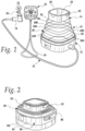
- the present disclosure is directed to a trans-anal irrigation (TAI) device which is shown generally at 10 in Fig. 1 where it is shown deployed for use.
- the main components of the device 10 include a pump base unit 12, an irrigation fluid reservoir 14, fluid tubing 16, a connector hub 18, a disposable rectal catheter 20, and a wireless controller 22, with an optional lanyard 24 attached to the controller.
- the reservoir 14 has a flexible side wall 26 that extends from an upstanding outer wall 28 at the bottom to a collar 30 at the top. Both the outer wall 28 and the collar 30 are relatively rigid. Although it is not shown here, it will be understood that the outer wall 28 is attached to a generally horizontal, relatively rigid bottom wall or base. The bottom wall or base has a generally square shape with rounded corners. The upstanding outer wall 28 is attached to and extends around the perimeter of the horizontal bottom wall. Preferably the bottom wall and outer wall 28 are molded as a single unit. The lower end of the flexible side wall 26 overlaps and is fixed to the interior surface of the outer wall 28 in sealing engagement. The upper end of the flexible side wall is fixed to the collar 30.
- the collar 30 has a handle 32 pivotably connected to it. A user can pivot the handle up 90° from the position illustrated in Fig. 1 to carry the reservoir 14.
- the collar 30 defines an opening 33 at the top of the reservoir. This opening may receive a funnel (not shown) therein.
- the funnel may have a fill tube connected to it. The funnel can be removed from the collar 30 and placed underneath a faucet for filling the reservoir. The free end of the fill tube would be placed through the collar 30 and into the reservoir cavity for this purpose. Water from the faucet flows through the funnel and fill tube and into the reservoir 14.
- the reservoir bottom wall will have a valve in it that provides selectable fluid communication between the interior of the reservoir and a conduit joined to one of the pump flow control valves.
- the valve automatically closes when the reservoir 14 is removed from the pump base unit 12 and automatically opens when the reservoir is mounted on the pump base unit 12.
- the pump base unit may also mount a temperature sensor (not shown) that electronically communicates with the controller 22.
- the flexible side wall 26 is formed by three step sections of progressively smaller outer dimension from bottom to top. Successive riser segments of the flexible side wall are joined by an intervening tread segment. The junctions between the riser and tread segments form flexible hinges that provide an overall stair-stepped construction to the expanded reservoir.
- the side wall 26 functions somewhat in the nature of a bellows and permits the reservoir to be telescopically expanded (as shown in Fig. 1 ) during use and collapsed (as shown in Fig. 2 ) during storage.
- Fig. 2 illustrates a few details of the pump base unit 12. It has a generally hollow shell 90 which includes a perimeter wall 94.
- the wall 94 surrounds the lower portion of the outer wall 28 of the reservoir 14 when the reservoir is installed on the pump base unit 12.
- the wall 94 has a handle 96 pivotably connected to it. A user can pivot the handle up 90° from the position illustrated in Fig. 2 to carry the pump base unit 12.
- a hollow cover 100 is removed from the top of the shell 90 and turned over to fit underneath the floor of the shell as seen in Fig. 2 .
- the cover 100 fits over the reservoir and removably joins the wall 94 to form a compact structure for storage or transport.
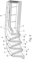
- the flexible side wall 26 of the reservoir 14 has a corrugated or bellows-like construction formed by three steps which are nested together.
- a lower step 34 a middle step 36 and an upper step 38.
- Each step comprises a riser segment and a tread segment which are pivotably connected to one another at an external hinge.
- the risers for the three steps are designated 34A, 36A and 38A, respectively.
- the treads are designated 34B, 36B and 38B, respectively.
- the external hinges are designated 34C, 36C and 38C, respectively.
- the steps are also pivotably connected to each other.
- the lower and middle steps 34, 36 are pivotably connected to one another at a first internal hinge 40.
- the middle and upper steps 36, 38 are pivotably connected to one another at a second internal hinge 42.
- the upper step 38 is pivotably connected at a third internal hinge 44 to a collar connector 46.
- the collar connector 46 has a generally vertical riser segment 48 that is somewhat truncated compared to the riser segments of the steps.
- the riser segment 48 is integrally attached to a horizontally disposed flange 50.
- the flange 50 is fixed to the rigid collar 30 which forms the top of the reservoir.
- the upward arrows 52 in Fig. 3 indicate where an expanding force on the flange 50 would be applied.
- the downward arrows 54 in Fig. 3 indicate where a collapsing force would be applied to the flange 50.
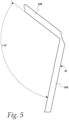
- Figs. 5 and 6 Some of the design parameters of the flexible wall are shown in Figs. 5 and 6 and include the following:
- the dimensions and geometry of the step segments and hinges are important to making the reservoir perform as desired.
- the collapsed, acute step angle must be greater than 18° and more preferably greater than 23°.
- the hinge thickness must be less than 0.8 mm and more preferably about 0.4 mm.
- the expanded, obtuse step angle must be greater than 110° but no more than 115° and more preferably 115°.
- the number of steps in combination with the foregoing preferences was found to be important as well. Limiting the number of steps to three and limiting the obtuse step angle when expanded to about 115° allows all hinges to fold properly.
- the reservoir is manufactured using silicone rubber (durometer 50 Shore A).
- durometer 50 Shore A The material durometer does not impact the dynamics of the reservoir as it is expanded and collapsed, but it will change the force required by the user to collapse or expand it.
- the material could have different characteristics and can be easily changed once a tool has been built.
- the material properties may be as shown in the following table: Table 1. Material Properties Parameter Value Young's Modulus 1.707 MPa Poisson's Ratio 0.3 Tensile Strength 6.6 MPa Yield Strength 12.2 MPa Density 2e-6 kg/m 3
- the flexible wall 26 of Fig. 6 shows the adjacent pairs of step segments are mirror images of each other.
- tread 34B is a mirror image of its immediate neighbor
- riser 36A and riser 36A is a mirror image of tread 36B
- riser 34A is not a mirror image of its tread 34B because riser 34A is longer than tread 34 and does not have a hinge formed at its base.
- the step segments are symmetric about bisectors through internal hinges 40 and 42 and external hinges 36C and 38C.
- each segment has an elongated external face (one of which is designated 52) and an elongated internal face (one of which is designated 54). Elongated faces 52 and 54 are parallel to one another. Then at each end there is an angled run extending from the elongated face to the arcuate portions of the hinge. Thus, the external face 52 joins an angled run 56 and the internal face 54 joins an angled run 58. The angled runs 56, 58 are parallel to one another. This segment shape assures that the folding of the steps occurs at the hinges and that the elongated body portions of the step will not buckle.
Landscapes
- Health & Medical Sciences (AREA)
- Engineering & Computer Science (AREA)
- Anesthesiology (AREA)
- Biomedical Technology (AREA)
- Heart & Thoracic Surgery (AREA)
- Hematology (AREA)
- Life Sciences & Earth Sciences (AREA)
- Animal Behavior & Ethology (AREA)
- General Health & Medical Sciences (AREA)
- Public Health (AREA)
- Veterinary Medicine (AREA)
- Prostheses (AREA)
- External Artificial Organs (AREA)
- Infusion, Injection, And Reservoir Apparatuses (AREA)
Description
- The present application claims the benefit of and priority to
U.S. Provisional Application No. 62/526,837, filed June 29, 2017 - The present disclosure is directed to a collapsible and expandable liquid supply reservoir. More particularly, a portable reservoir is disclosed for medical applications such as trans-anal irrigation (TAI) or antegrade irrigation such as colostomy/stoma irrigation.
- Many individuals suffering spinal cord injury and other medical conditions may need to avail themselves of bowel management treatments. Trans-anal irrigation (TAl) provides one option for bowel management. TAI is the delivery of irrigating liquid (usually water) into the colon to flush the system of stool and create pseudo-continence for the user. Systems currently on the market allow the user to utilize a product over the toilet, on a commode/shower chair or in a bed to introduce water into the bowel through a rectal catheter. The user will introduce an amount of water into the bowel (typically 500-700 mL) in order to flush out stool located in the bowel passage. The user will typically introduce the water, wait for a period of time and allow gravity to flush the water and stool out of the body. The rectal catheter may have an inflatable/deflatable balloon to assist in retention of the catheter during water introduction. A particularly suitable TAI device is shown in
U.S. Patent Applications Serial No. 62/360,014, filed July 8, 2016 Serial No. 62/460,502, filed February 17, 2017 WO 2018/009871, published January 11, 2018 . - The typical TAI device has an irrigation liquid reservoir and a pump base unit which contains a pump for pumping water from the reservoir through suitable tubing to the catheter. Optionally the reservoir may be made separable from the pump base unit and tubing. This makes filling the reservoir easier since just the reservoir can be carried to a faucet to fill it, without the need to move the pump base unit or tubing along with the reservoir. Alternately, the reservoir may be integrated with the pump base unit.
- It is desirable that when the reservoir is not in use, it can be collapsed to minimize the volume of the device for storage. When in use the reservoir expands and creates an enclosure that contains water used for irrigation and retention balloon inflation. Among the challenges faced in designing a reservoir for use with a TAI device is the reservoir must withstand long-term use wherein it will be frequently expanded and collapsed. Furthermore, users often have limited dexterity so the reservoir must perform correctly without requiring fine motor skills on the part of the user.
- Problems encountered in some designs of a collapsible reservoir include: failing to collapse completely; requiring too large of a force to collapse the reservoir; failing to remain in the collapsed or expanded position as desired; substantial buckling of the reservoir walls as it is collapsed; and sagging or drooping of the walls when in the expanded position. Buckling is a torsional motion within the thicker wall segments, which leads to incomplete or unpredictable collapse and the result that the flexible wall segments do not nest together properly. The present disclosure is directed to a new reservoir design that will address these items by: causing the reservoir to expand and collapse fully and then remain in the collapsed and expanded positions as desired, i.e., there is no snapping back up or down; reducing the force required to collapse the reservoir; and eliminating any buckling or instability as the reservoir expands or collapses.
US1718369 discloses irrigation bags of a foldable or collapsible structure which can be readily folded and placed in a compact space for moving, storing, or when traveling. The bags have substantially similar collapsible sections which collapse on top on each other.US20050127074 discloses molded plastic containers for use including storage of food items, which can be sealed. The food containers are collapsible or foldable to a compact position when empty for storage purposes.US1901069 discloses collapsible fountain syringes of the bellows type that will occupy a small depth when collapsed. - The invention is defined by the features of independent claim 1. In one aspect, the present disclosure concerns a water supply for a TAI or colostomy/stoma irrigation device having a reservoir mounted on a pump base unit. The reservoir is collapsible for storage and expandable for use. It has a flexible wall having a corrugated or bellows-like construction formed by three steps which are nested together. There is a lower step, a middle step and an upper step. Each step comprises a riser and a tread which are pivotably connected to one another at an external hinge. The lower and middle steps in turn are pivotably connected to one another at a first internal hinge. Similarly, the middle and upper steps are pivotably connected to one another at a second internal hinge. Finally, the upper step is pivotably connected to a collar connector at a third internal hinge.
- To improve manufacturability and to minimize production costs, the reservoir of the present disclosure will be manufactured in the collapsed position. A suitable manufacturing method is compression molding, although other methods are possible. The overall shape of the reservoir can be described as a truncated pyramid. That is, the reservoir has a generally square base but with rounded corners. Its flexible wall is joined to the perimeter of the square base and comprises four trapezoidal side panels which incorporate the three steps. The trapezoidal side panels are joined to one another at rounded corners. The side panels converge toward the top where they are attached to a generally square collar at the top of the panels. The pyramidal shape of the side walls permits the reservoir to mate with a square pump base unit. Having a square pump base unit is advantageous in terms of fitting the pump, batteries, solenoid valves, tubing and circuit board in the pump base unit.
-
-
Fig. 1 is a perspective view of TAI device having the reservoir of the present disclosure, shown here mounted on the pump base unit and in the expanded position. -
Fig. 2 is a perspective view of the pump base unit with the reservoir mounted thereon and in the collapsed position. -
Fig. 3 is a perspective view of a quarter section of the flexible portion of the reservoir wall in the collapsed position, generally looking at the exterior of the wall. -
Fig. 4 is a perspective view of a quarter section of the flexible portion of the reservoir wall in the collapsed position, generally looking at the interior of the wall. -
Fig. 5 is a section through the flexible portion of the reservoir wall, looking at the lower reservoir step in the expanded position. -
Fig. 6 is a half section through the flexible portion of the reservoir wall, looking at all of the reservoir steps in the collapsed position, with the length dimensions shown being in millimeters. - The present disclosure is directed to a trans-anal irrigation (TAI) device which is shown generally at 10 in
Fig. 1 where it is shown deployed for use. The main components of thedevice 10 include apump base unit 12, anirrigation fluid reservoir 14,fluid tubing 16, aconnector hub 18, a disposablerectal catheter 20, and a wireless controller 22, with anoptional lanyard 24 attached to the controller. - The
reservoir 14 has aflexible side wall 26 that extends from an upstandingouter wall 28 at the bottom to acollar 30 at the top. Both theouter wall 28 and thecollar 30 are relatively rigid. Although it is not shown here, it will be understood that theouter wall 28 is attached to a generally horizontal, relatively rigid bottom wall or base. The bottom wall or base has a generally square shape with rounded corners. The upstandingouter wall 28 is attached to and extends around the perimeter of the horizontal bottom wall. Preferably the bottom wall andouter wall 28 are molded as a single unit. The lower end of theflexible side wall 26 overlaps and is fixed to the interior surface of theouter wall 28 in sealing engagement. The upper end of the flexible side wall is fixed to thecollar 30. - The
collar 30 has ahandle 32 pivotably connected to it. A user can pivot the handle up 90° from the position illustrated inFig. 1 to carry thereservoir 14. Thecollar 30 defines anopening 33 at the top of the reservoir. This opening may receive a funnel (not shown) therein. The funnel may have a fill tube connected to it. The funnel can be removed from thecollar 30 and placed underneath a faucet for filling the reservoir. The free end of the fill tube would be placed through thecollar 30 and into the reservoir cavity for this purpose. Water from the faucet flows through the funnel and fill tube and into thereservoir 14. - It will be understood if the reservoir is removable from the pump base unit then the reservoir bottom wall will have a valve in it that provides selectable fluid communication between the interior of the reservoir and a conduit joined to one of the pump flow control valves. The valve automatically closes when the
reservoir 14 is removed from thepump base unit 12 and automatically opens when the reservoir is mounted on thepump base unit 12. The pump base unit may also mount a temperature sensor (not shown) that electronically communicates with the controller 22. - The
flexible side wall 26 is formed by three step sections of progressively smaller outer dimension from bottom to top. Successive riser segments of the flexible side wall are joined by an intervening tread segment. The junctions between the riser and tread segments form flexible hinges that provide an overall stair-stepped construction to the expanded reservoir. Thus, theside wall 26 functions somewhat in the nature of a bellows and permits the reservoir to be telescopically expanded (as shown inFig. 1 ) during use and collapsed (as shown inFig. 2 ) during storage. -
Fig. 2 illustrates a few details of thepump base unit 12. It has a generallyhollow shell 90 which includes aperimeter wall 94. Thewall 94 surrounds the lower portion of theouter wall 28 of thereservoir 14 when the reservoir is installed on thepump base unit 12. Thewall 94 has ahandle 96 pivotably connected to it. A user can pivot the handle up 90° from the position illustrated inFig. 2 to carry thepump base unit 12. During use of the device ahollow cover 100 is removed from the top of theshell 90 and turned over to fit underneath the floor of the shell as seen inFig. 2 . During storage thecover 100 fits over the reservoir and removably joins thewall 94 to form a compact structure for storage or transport. - Further details of the
flexible side wall 26 of thereservoir 14 will now be described in connection withFigs. 3 - 6 . The flexible side wall has a corrugated or bellows-like construction formed by three steps which are nested together. There is alower step 34, amiddle step 36 and anupper step 38. Each step comprises a riser segment and a tread segment which are pivotably connected to one another at an external hinge. The risers for the three steps are designated 34A, 36A and 38A, respectively. The treads are designated 34B, 36B and 38B, respectively. The external hinges are designated 34C, 36C and 38C, respectively. The steps are also pivotably connected to each other. Thus, the lower andmiddle steps internal hinge 40. Similarly, the middle andupper steps internal hinge 42. Finally, theupper step 38 is pivotably connected at a thirdinternal hinge 44 to acollar connector 46. - The
collar connector 46 has a generallyvertical riser segment 48 that is somewhat truncated compared to the riser segments of the steps. Theriser segment 48 is integrally attached to a horizontally disposedflange 50. Theflange 50 is fixed to therigid collar 30 which forms the top of the reservoir. Theupward arrows 52 inFig. 3 indicate where an expanding force on theflange 50 would be applied. Similarly, thedownward arrows 54 inFig. 3 indicate where a collapsing force would be applied to theflange 50. - Some of the design parameters of the flexible wall are shown in
Figs. 5 and6 and include the following: - A) The step angle is defined as the non-reflex angle between the riser and tread segments of a particular step. There is an obtuse step angle, when the reservoir is expanded, and an acute step angle, when the reservoir is collapsed. As seen in
Fig. 6 the collapsed, acute step angle is 23.37°. As seen inFig. 5 the expanded, obtuse step angle is 115°. Both step angles are measured after a user expands or collapses the reservoir and releases it to a stable position. - B) The segment thickness is shown for
tread 34B as 2.286 mm. - C) The riser length is shown for
riser 34A as 16.076 mm. - D) The tread length is shown for
tread 34B as 12.882 mm. - E) A first, straight angled run portion of the
external hinge 34C, i.e, the hinge length, is shown as 2.713 mm. - F) The inside radius of
external hinge 34C is shown as R0.500 mm. - G) The outside radius of
external hinge 34C is shown as R1.880 mm. - H) The hinge thickness of
external hinge 34C is shown as 0.400 mm. - I) The hinge angle between the outer surface of the
riser 34A and the first angled run portion of theexternal hinge 34C is shown as 150°. - It has been found that the dimensions and geometry of the step segments and hinges are important to making the reservoir perform as desired. In particular, the collapsed, acute step angle must be greater than 18° and more preferably greater than 23°. The hinge thickness must be less than 0.8 mm and more preferably about 0.4 mm. The expanded, obtuse step angle must be greater than 110° but no more than 115° and more preferably 115°. Similarly, the number of steps in combination with the foregoing preferences was found to be important as well. Limiting the number of steps to three and limiting the obtuse step angle when expanded to about 115° allows all hinges to fold properly.
- The reservoir is manufactured using silicone rubber (
durometer 50 Shore A). The material durometer does not impact the dynamics of the reservoir as it is expanded and collapsed, but it will change the force required by the user to collapse or expand it. The material could have different characteristics and can be easily changed once a tool has been built. The material properties may be as shown in the following table:Table 1. Material Properties Parameter Value Young's Modulus 1.707 MPa Poisson's Ratio 0.3 Tensile Strength 6.6 MPa Yield Strength 12.2 MPa Density 2e-6 kg/m3 - In this table the durometer (50 Shore A) is converted to Young's Modulus using the formula: exp((Shore-A Durometer)*0.0235-0.6403). The tensile strength and yield strength value were obtained from Silicone Material Selection Guide.
- With the design as shown all collapsing and expansion motion is isolated to the thin hinge sections while the thicker segments remain essentially rigid. It is preferred that the flexible portion of the reservoir be molded in the collapsed position as it is easier to manufacture this way. A draft angle of greater than 0.5° is preferred, such as the 1.0° draft angle shown in
Fig. 6 . - Further, it will be noted that other than
riser 34A, theflexible wall 26 ofFig. 6 shows the adjacent pairs of step segments are mirror images of each other. For example,tread 34B is a mirror image of its immediate neighbor,riser 36A andriser 36A is a mirror image oftread 36B, and so on.Riser 34A is not a mirror image of itstread 34B becauseriser 34A is longer thantread 34 and does not have a hinge formed at its base. Thus, the step segments are symmetric about bisectors throughinternal hinges external hinges - It is also pointed out that the cross-sections of
symmetric step segments Fig. 6 , each segment has an elongated external face (one of which is designated 52) and an elongated internal face (one of which is designated 54). Elongated faces 52 and 54 are parallel to one another. Then at each end there is an angled run extending from the elongated face to the arcuate portions of the hinge. Thus, theexternal face 52 joins anangled run 56 and theinternal face 54 joins anangled run 58. The angled runs 56, 58 are parallel to one another. This segment shape assures that the folding of the steps occurs at the hinges and that the elongated body portions of the step will not buckle. - It should be understood that various changes and modifications to the presently preferred embodiments described herein will be apparent to those skilled in the art. The invention is defined by the features of independent claim 1.
Claims (10)
- A collapsible irrigation device liquid reservoir (14) for colostomy/stoma irrigation, comprising a flexible side wall (26) having a lower step (34), a middle step (36) and an upper step (38), wherein the steps are of progressively smaller outer dimension from bottom to top, each of the steps comprising a riser segment (34A, 36A, 38A) and a tread segment (34B, 36B, 38B) pivotably connected to one another at an external hinge (34C, 36C, 38C), the step when collapsed defining an acute step angle between the riser and tread segments of about 23°, and the step when expanded defining an obtuse step angle between the riser and tread segments of about 115°, the tread of the lower step being pivotably connected to the riser of the middle step at a first internal hinge (40), and the tread of the middle step being pivotably connected to the riser of the upper step at a second internal hinge (42) .
- The collapsible irrigation device liquid reservoir of claim 1 wherein each of the hinges has a hinge thickness of about 0.4 mm.
- The collapsible irrigation device liquid reservoir of claim 2 wherein internal and external hinges each have an internal radius of about 0.500 mm and an external radius of about 1.880 mm.
- The collapsible irrigation device liquid reservoir of claim 3 wherein the riser and tread segments have a width of about 2.286 mm.
- The collapsible irrigation device liquid reservoir of claim 4 wherein the internal and external hinges have a first angled run portion whose length is about 2.713 mm.
- The collapsible irrigation device liquid reservoir of claim 5 wherein the hinge angle between the first angled run portion and its adjacent riser segment is about 150°.
- The collapsible irrigation device liquid reservoir of claim 6 wherein the riser segment of the lower step has a length of about 16.076 mm.
- The collapsible irrigation device liquid reservoir of claim 7 wherein the tread segment of the lower step has a length of about 12.882 mm.
- The collapsible irrigation device liquid reservoir of claim 1 further comprising a collar connector (46) pivotably connected to the tread of the upper step at a third internal hinge (44).
- The collapsible irrigation device liquid reservoir of claim 9 wherein the collar connector has a vertical riser segment (48) connected to a horizontally disposed flange (50).
Applications Claiming Priority (2)
| Application Number | Priority Date | Filing Date | Title |
|---|---|---|---|
| US201762526837P | 2017-06-29 | 2017-06-29 | |
| PCT/US2018/039561 WO2019005836A1 (en) | 2017-06-29 | 2018-06-26 | Collapsible liquid reservoir |
Publications (2)
| Publication Number | Publication Date |
|---|---|
| EP3645075A1 EP3645075A1 (en) | 2020-05-06 |
| EP3645075B1 true EP3645075B1 (en) | 2024-09-04 |
Family
ID=62981341
Family Applications (1)
| Application Number | Title | Priority Date | Filing Date |
|---|---|---|---|
| EP18743645.6A Active EP3645075B1 (en) | 2017-06-29 | 2018-06-26 | Collapsible liquid reservoir |
Country Status (8)
| Country | Link |
|---|---|
| US (1) | US11446426B2 (en) |
| EP (1) | EP3645075B1 (en) |
| AU (1) | AU2018290798B2 (en) |
| CA (1) | CA3068454C (en) |
| DK (1) | DK3645075T3 (en) |
| HU (1) | HUE069325T2 (en) |
| LT (1) | LT3645075T (en) |
| WO (1) | WO2019005836A1 (en) |
Families Citing this family (11)
| Publication number | Priority date | Publication date | Assignee | Title |
|---|---|---|---|---|
| CN111601545B (en) | 2017-11-09 | 2024-05-07 | 康沃特克科技公司 | Ostomy monitoring systems and methods |
| USD867600S1 (en) | 2017-11-14 | 2019-11-19 | Hollister Incorporated | Controller with a user interface |
| USD867601S1 (en) * | 2017-11-20 | 2019-11-19 | Hollister Incorporated | Controller with a user interface |
| US11202879B2 (en) * | 2017-12-29 | 2021-12-21 | Koninklijke Philips N.V. | Humidifier and airway pressure support system including same |
| USD893514S1 (en) | 2018-11-08 | 2020-08-18 | 11 Health And Technologies Limited | Display screen or portion thereof with graphical user interface |
| US11590018B2 (en) | 2019-05-14 | 2023-02-28 | Medline Industries, Lp | Fecal management applicator and assembly |
| USD939696S1 (en) * | 2019-05-14 | 2021-12-28 | Medline Industries, Lp | Applicator |
| CA3198681A1 (en) | 2020-10-15 | 2022-04-21 | Convatec Technologies Inc. | Ostomy systems and methods |
| KR102423041B1 (en) * | 2020-10-29 | 2022-07-19 | 남경호 | Assembly Cooking Container |
| US20240001023A1 (en) * | 2020-11-24 | 2024-01-04 | Coloplast A/S | Liquid container for an Anal Irrigation System |
| US12268840B2 (en) * | 2021-01-22 | 2025-04-08 | Proportion-Air, Inc | System for dispensing fluid |
Family Cites Families (19)
| Publication number | Priority date | Publication date | Assignee | Title |
|---|---|---|---|---|
| US1718369A (en) | 1926-05-08 | 1929-06-25 | Lillford Harry John | Collapsible irrigation bag |
| US1901069A (en) * | 1930-05-10 | 1933-03-14 | William A Bryans | Collapsible fountain syringe |
| US4014332A (en) * | 1973-08-20 | 1977-03-29 | Sneider Vincent R | Disposable syringes |
| US5632406A (en) * | 1995-10-11 | 1997-05-27 | Robbins, Iii; Edward S. | Side wall construction for collapsible containers |
| GB2351062B (en) * | 2000-06-14 | 2001-05-30 | Dalmian Frank Rapson | Sealable multicompartment container |
| WO2003030968A1 (en) | 2001-10-12 | 2003-04-17 | Coloplast A/S | Bowel irrigation system and probe therefore |
| CA2463081A1 (en) | 2001-10-15 | 2003-04-24 | Gerenraich Family Trust | Touch free dispenser |
| US7654402B2 (en) * | 2003-12-16 | 2010-02-02 | Dart Industries Inc. | Collapsible container |
| US7118050B1 (en) | 2005-07-20 | 2006-10-10 | Chiang-Pei Chen | Sprayer with changeable volume |
| KR200411940Y1 (en) | 2006-01-02 | 2006-03-21 | 유병언 | Folding bucket of temperature controlled portable washer |
| NL2006515C2 (en) * | 2011-04-01 | 2012-10-02 | Willemsen | HOLDER WITH A VOLUME FOR ACCOMMODATING A LIQUID MATERIAL. |
| US9044082B2 (en) | 2012-04-20 | 2015-06-02 | Dart Industries Inc. | Collapsible container |
| HUE028926T2 (en) | 2012-06-07 | 2017-01-30 | Dentsply Ih Ab | Irrigation system with pre-loaded irrigation liquid reservoir |
| US9296508B2 (en) | 2012-12-13 | 2016-03-29 | Gojo Industries, Inc. | Collapsible containers and refill units |
| HUE027578T2 (en) | 2013-06-03 | 2016-10-28 | Dentsply Ih Ab | Cylindrical collapsible container |
| DE202014101047U1 (en) * | 2014-03-10 | 2014-07-02 | Sam Tung Tsui | Foldable household containers |
| AU2015317451B2 (en) * | 2014-09-19 | 2019-11-14 | Coloplast A/S | A container |
| CN107000881B (en) * | 2014-10-02 | 2019-03-19 | S.I.P.A.工业设计自动化合伙股份有限公司 | Collapsible plastic bottle for water dispenser |
| JP6821779B2 (en) | 2016-07-08 | 2021-01-27 | ホリスター・インコーポレイテッドHollister Incorporated | Transanal enema therapy device |
-
2018
- 2018-06-26 AU AU2018290798A patent/AU2018290798B2/en active Active
- 2018-06-26 US US16/626,972 patent/US11446426B2/en active Active
- 2018-06-26 CA CA3068454A patent/CA3068454C/en active Active
- 2018-06-26 LT LTEPPCT/US2018/039561T patent/LT3645075T/en unknown
- 2018-06-26 HU HUE18743645A patent/HUE069325T2/en unknown
- 2018-06-26 DK DK18743645.6T patent/DK3645075T3/en active
- 2018-06-26 EP EP18743645.6A patent/EP3645075B1/en active Active
- 2018-06-26 WO PCT/US2018/039561 patent/WO2019005836A1/en not_active Ceased
Also Published As
| Publication number | Publication date |
|---|---|
| AU2018290798A1 (en) | 2020-01-30 |
| HUE069325T2 (en) | 2025-03-28 |
| LT3645075T (en) | 2024-09-25 |
| CA3068454A1 (en) | 2019-01-03 |
| DK3645075T3 (en) | 2024-09-09 |
| US11446426B2 (en) | 2022-09-20 |
| US20200215256A1 (en) | 2020-07-09 |
| WO2019005836A1 (en) | 2019-01-03 |
| EP3645075A1 (en) | 2020-05-06 |
| CA3068454C (en) | 2023-06-20 |
| AU2018290798B2 (en) | 2024-05-30 |
Similar Documents
| Publication | Publication Date | Title |
|---|---|---|
| CA3068454C (en) | Collapsible liquid reservoir | |
| US10350345B2 (en) | Cylindrical collapsible container | |
| ES2710359T3 (en) | Device for stool drainage | |
| US11541163B2 (en) | Hollow organ irrigation systems | |
| US11033161B2 (en) | Ergonomic toilet equipment | |
| US20120204340A1 (en) | Portable tub | |
| CN101801434B (en) | Container for an anal irrigation system | |
| CA2960909A1 (en) | A collapsible container for an irrigation system | |
| KR101141630B1 (en) | Moving type apparatus for bath | |
| KR102295033B1 (en) | Air Mat Having Height Adjustment Structure | |
| EP4175694B1 (en) | An irrigation system | |
| CN111632222A (en) | Multipurpose anus intestine and prostate physiotherapy bidet | |
| CN110811399B (en) | Auxiliary appliance | |
| CN207136979U (en) | One kind inflates flat closestool | |
| CN201019616Y (en) | Bathtub with changing volume | |
| JP6585455B2 (en) | Ostomate-compatible toilet and waste disposal system | |
| JPH10290823A (en) | Stationary-type expansion bathtub for care and its unit | |
| KR100895107B1 (en) | Human bowel bowel movements | |
| JPH11113773A (en) | Assembling bathtub and bathing equipment using it |
Legal Events
| Date | Code | Title | Description |
|---|---|---|---|
| STAA | Information on the status of an ep patent application or granted ep patent |
Free format text: STATUS: UNKNOWN |
|
| STAA | Information on the status of an ep patent application or granted ep patent |
Free format text: STATUS: THE INTERNATIONAL PUBLICATION HAS BEEN MADE |
|
| PUAI | Public reference made under article 153(3) epc to a published international application that has entered the european phase |
Free format text: ORIGINAL CODE: 0009012 |
|
| STAA | Information on the status of an ep patent application or granted ep patent |
Free format text: STATUS: REQUEST FOR EXAMINATION WAS MADE |
|
| 17P | Request for examination filed |
Effective date: 20200103 |
|
| AK | Designated contracting states |
Kind code of ref document: A1 Designated state(s): AL AT BE BG CH CY CZ DE DK EE ES FI FR GB GR HR HU IE IS IT LI LT LU LV MC MK MT NL NO PL PT RO RS SE SI SK SM TR |
|
| AX | Request for extension of the european patent |
Extension state: BA ME |
|
| DAV | Request for validation of the european patent (deleted) | ||
| DAX | Request for extension of the european patent (deleted) | ||
| STAA | Information on the status of an ep patent application or granted ep patent |
Free format text: STATUS: EXAMINATION IS IN PROGRESS |
|
| 17Q | First examination report despatched |
Effective date: 20220609 |
|
| P01 | Opt-out of the competence of the unified patent court (upc) registered |
Effective date: 20230520 |
|
| GRAP | Despatch of communication of intention to grant a patent |
Free format text: ORIGINAL CODE: EPIDOSNIGR1 |
|
| STAA | Information on the status of an ep patent application or granted ep patent |
Free format text: STATUS: GRANT OF PATENT IS INTENDED |
|
| INTG | Intention to grant announced |
Effective date: 20240514 |
|
| GRAS | Grant fee paid |
Free format text: ORIGINAL CODE: EPIDOSNIGR3 |
|
| GRAA | (expected) grant |
Free format text: ORIGINAL CODE: 0009210 |
|
| STAA | Information on the status of an ep patent application or granted ep patent |
Free format text: STATUS: THE PATENT HAS BEEN GRANTED |
|
| AK | Designated contracting states |
Kind code of ref document: B1 Designated state(s): AL AT BE BG CH CY CZ DE DK EE ES FI FR GB GR HR HU IE IS IT LI LT LU LV MC MK MT NL NO PL PT RO RS SE SI SK SM TR |
|
| REG | Reference to a national code |
Ref country code: GB Ref legal event code: FG4D |
|
| REG | Reference to a national code |
Ref country code: DK Ref legal event code: T3 Effective date: 20240906 |
|
| REG | Reference to a national code |
Ref country code: NL Ref legal event code: FP |
|
| REG | Reference to a national code |
Ref country code: CH Ref legal event code: EP |
|
| REG | Reference to a national code |
Ref country code: IE Ref legal event code: FG4D |
|
| REG | Reference to a national code |
Ref country code: DE Ref legal event code: R096 Ref document number: 602018073952 Country of ref document: DE |
|
| PG25 | Lapsed in a contracting state [announced via postgrant information from national office to epo] |
Ref country code: NO Free format text: LAPSE BECAUSE OF FAILURE TO SUBMIT A TRANSLATION OF THE DESCRIPTION OR TO PAY THE FEE WITHIN THE PRESCRIBED TIME-LIMIT Effective date: 20241204 |
|
| PG25 | Lapsed in a contracting state [announced via postgrant information from national office to epo] |
Ref country code: FI Free format text: LAPSE BECAUSE OF FAILURE TO SUBMIT A TRANSLATION OF THE DESCRIPTION OR TO PAY THE FEE WITHIN THE PRESCRIBED TIME-LIMIT Effective date: 20240904 Ref country code: PL Free format text: LAPSE BECAUSE OF FAILURE TO SUBMIT A TRANSLATION OF THE DESCRIPTION OR TO PAY THE FEE WITHIN THE PRESCRIBED TIME-LIMIT Effective date: 20240904 Ref country code: GR Free format text: LAPSE BECAUSE OF FAILURE TO SUBMIT A TRANSLATION OF THE DESCRIPTION OR TO PAY THE FEE WITHIN THE PRESCRIBED TIME-LIMIT Effective date: 20241205 |
|
| PG25 | Lapsed in a contracting state [announced via postgrant information from national office to epo] |
Ref country code: BG Free format text: LAPSE BECAUSE OF FAILURE TO SUBMIT A TRANSLATION OF THE DESCRIPTION OR TO PAY THE FEE WITHIN THE PRESCRIBED TIME-LIMIT Effective date: 20240904 |
|
| PG25 | Lapsed in a contracting state [announced via postgrant information from national office to epo] |
Ref country code: LV Free format text: LAPSE BECAUSE OF FAILURE TO SUBMIT A TRANSLATION OF THE DESCRIPTION OR TO PAY THE FEE WITHIN THE PRESCRIBED TIME-LIMIT Effective date: 20240904 |
|
| PG25 | Lapsed in a contracting state [announced via postgrant information from national office to epo] |
Ref country code: HR Free format text: LAPSE BECAUSE OF FAILURE TO SUBMIT A TRANSLATION OF THE DESCRIPTION OR TO PAY THE FEE WITHIN THE PRESCRIBED TIME-LIMIT Effective date: 20240904 |
|
| PG25 | Lapsed in a contracting state [announced via postgrant information from national office to epo] |
Ref country code: ES Free format text: LAPSE BECAUSE OF FAILURE TO SUBMIT A TRANSLATION OF THE DESCRIPTION OR TO PAY THE FEE WITHIN THE PRESCRIBED TIME-LIMIT Effective date: 20240904 Ref country code: RS Free format text: LAPSE BECAUSE OF FAILURE TO SUBMIT A TRANSLATION OF THE DESCRIPTION OR TO PAY THE FEE WITHIN THE PRESCRIBED TIME-LIMIT Effective date: 20241204 |
|
| PG25 | Lapsed in a contracting state [announced via postgrant information from national office to epo] |
Ref country code: RS Free format text: LAPSE BECAUSE OF FAILURE TO SUBMIT A TRANSLATION OF THE DESCRIPTION OR TO PAY THE FEE WITHIN THE PRESCRIBED TIME-LIMIT Effective date: 20241204 Ref country code: PL Free format text: LAPSE BECAUSE OF FAILURE TO SUBMIT A TRANSLATION OF THE DESCRIPTION OR TO PAY THE FEE WITHIN THE PRESCRIBED TIME-LIMIT Effective date: 20240904 Ref country code: NO Free format text: LAPSE BECAUSE OF FAILURE TO SUBMIT A TRANSLATION OF THE DESCRIPTION OR TO PAY THE FEE WITHIN THE PRESCRIBED TIME-LIMIT Effective date: 20241204 Ref country code: LV Free format text: LAPSE BECAUSE OF FAILURE TO SUBMIT A TRANSLATION OF THE DESCRIPTION OR TO PAY THE FEE WITHIN THE PRESCRIBED TIME-LIMIT Effective date: 20240904 Ref country code: HR Free format text: LAPSE BECAUSE OF FAILURE TO SUBMIT A TRANSLATION OF THE DESCRIPTION OR TO PAY THE FEE WITHIN THE PRESCRIBED TIME-LIMIT Effective date: 20240904 Ref country code: GR Free format text: LAPSE BECAUSE OF FAILURE TO SUBMIT A TRANSLATION OF THE DESCRIPTION OR TO PAY THE FEE WITHIN THE PRESCRIBED TIME-LIMIT Effective date: 20241205 Ref country code: FI Free format text: LAPSE BECAUSE OF FAILURE TO SUBMIT A TRANSLATION OF THE DESCRIPTION OR TO PAY THE FEE WITHIN THE PRESCRIBED TIME-LIMIT Effective date: 20240904 Ref country code: ES Free format text: LAPSE BECAUSE OF FAILURE TO SUBMIT A TRANSLATION OF THE DESCRIPTION OR TO PAY THE FEE WITHIN THE PRESCRIBED TIME-LIMIT Effective date: 20240904 Ref country code: BG Free format text: LAPSE BECAUSE OF FAILURE TO SUBMIT A TRANSLATION OF THE DESCRIPTION OR TO PAY THE FEE WITHIN THE PRESCRIBED TIME-LIMIT Effective date: 20240904 |
|
| REG | Reference to a national code |
Ref country code: AT Ref legal event code: MK05 Ref document number: 1719703 Country of ref document: AT Kind code of ref document: T Effective date: 20240904 |
|
| REG | Reference to a national code |
Ref country code: HU Ref legal event code: AG4A Ref document number: E069325 Country of ref document: HU |
|
| PG25 | Lapsed in a contracting state [announced via postgrant information from national office to epo] |
Ref country code: IS Free format text: LAPSE BECAUSE OF FAILURE TO SUBMIT A TRANSLATION OF THE DESCRIPTION OR TO PAY THE FEE WITHIN THE PRESCRIBED TIME-LIMIT Effective date: 20250104 Ref country code: PT Free format text: LAPSE BECAUSE OF FAILURE TO SUBMIT A TRANSLATION OF THE DESCRIPTION OR TO PAY THE FEE WITHIN THE PRESCRIBED TIME-LIMIT Effective date: 20250106 |
|
| PG25 | Lapsed in a contracting state [announced via postgrant information from national office to epo] |
Ref country code: SM Free format text: LAPSE BECAUSE OF FAILURE TO SUBMIT A TRANSLATION OF THE DESCRIPTION OR TO PAY THE FEE WITHIN THE PRESCRIBED TIME-LIMIT Effective date: 20240904 Ref country code: RO Free format text: LAPSE BECAUSE OF FAILURE TO SUBMIT A TRANSLATION OF THE DESCRIPTION OR TO PAY THE FEE WITHIN THE PRESCRIBED TIME-LIMIT Effective date: 20240904 |
|
| PG25 | Lapsed in a contracting state [announced via postgrant information from national office to epo] |
Ref country code: EE Free format text: LAPSE BECAUSE OF FAILURE TO SUBMIT A TRANSLATION OF THE DESCRIPTION OR TO PAY THE FEE WITHIN THE PRESCRIBED TIME-LIMIT Effective date: 20240904 Ref country code: AT Free format text: LAPSE BECAUSE OF FAILURE TO SUBMIT A TRANSLATION OF THE DESCRIPTION OR TO PAY THE FEE WITHIN THE PRESCRIBED TIME-LIMIT Effective date: 20240904 |
|
| PG25 | Lapsed in a contracting state [announced via postgrant information from national office to epo] |
Ref country code: CZ Free format text: LAPSE BECAUSE OF FAILURE TO SUBMIT A TRANSLATION OF THE DESCRIPTION OR TO PAY THE FEE WITHIN THE PRESCRIBED TIME-LIMIT Effective date: 20240904 |
|
| PG25 | Lapsed in a contracting state [announced via postgrant information from national office to epo] |
Ref country code: SK Free format text: LAPSE BECAUSE OF FAILURE TO SUBMIT A TRANSLATION OF THE DESCRIPTION OR TO PAY THE FEE WITHIN THE PRESCRIBED TIME-LIMIT Effective date: 20240904 Ref country code: IT Free format text: LAPSE BECAUSE OF FAILURE TO SUBMIT A TRANSLATION OF THE DESCRIPTION OR TO PAY THE FEE WITHIN THE PRESCRIBED TIME-LIMIT Effective date: 20240904 |
|
| REG | Reference to a national code |
Ref country code: DE Ref legal event code: R097 Ref document number: 602018073952 Country of ref document: DE |
|
| PLBE | No opposition filed within time limit |
Free format text: ORIGINAL CODE: 0009261 |
|
| STAA | Information on the status of an ep patent application or granted ep patent |
Free format text: STATUS: NO OPPOSITION FILED WITHIN TIME LIMIT |
|
| 26N | No opposition filed |
Effective date: 20250605 |
|
| PG25 | Lapsed in a contracting state [announced via postgrant information from national office to epo] |
Ref country code: SE Free format text: LAPSE BECAUSE OF FAILURE TO SUBMIT A TRANSLATION OF THE DESCRIPTION OR TO PAY THE FEE WITHIN THE PRESCRIBED TIME-LIMIT Effective date: 20240904 |
|
| PGFP | Annual fee paid to national office [announced via postgrant information from national office to epo] |
Ref country code: NL Payment date: 20250826 Year of fee payment: 8 |
|
| PGFP | Annual fee paid to national office [announced via postgrant information from national office to epo] |
Ref country code: HU Payment date: 20250822 Year of fee payment: 8 |
|
| PGFP | Annual fee paid to national office [announced via postgrant information from national office to epo] |
Ref country code: LT Payment date: 20250819 Year of fee payment: 8 Ref country code: DK Payment date: 20250825 Year of fee payment: 8 Ref country code: DE Payment date: 20250827 Year of fee payment: 8 |
|
| PGFP | Annual fee paid to national office [announced via postgrant information from national office to epo] |
Ref country code: GB Payment date: 20250827 Year of fee payment: 8 |
|
| PGFP | Annual fee paid to national office [announced via postgrant information from national office to epo] |
Ref country code: FR Payment date: 20250825 Year of fee payment: 8 |
|
| PGFP | Annual fee paid to national office [announced via postgrant information from national office to epo] |
Ref country code: IE Payment date: 20250827 Year of fee payment: 8 |
|
| REG | Reference to a national code |
Ref country code: CH Ref legal event code: H13 Free format text: ST27 STATUS EVENT CODE: U-0-0-H10-H13 (AS PROVIDED BY THE NATIONAL OFFICE) Effective date: 20260127 |
|
| PG25 | Lapsed in a contracting state [announced via postgrant information from national office to epo] |
Ref country code: MC Free format text: LAPSE BECAUSE OF FAILURE TO SUBMIT A TRANSLATION OF THE DESCRIPTION OR TO PAY THE FEE WITHIN THE PRESCRIBED TIME-LIMIT Effective date: 20240904 |
|
| PG25 | Lapsed in a contracting state [announced via postgrant information from national office to epo] |
Ref country code: LU Free format text: LAPSE BECAUSE OF NON-PAYMENT OF DUE FEES Effective date: 20250626 |
|
| REG | Reference to a national code |
Ref country code: BE Ref legal event code: MM Effective date: 20250630 |
|
| PG25 | Lapsed in a contracting state [announced via postgrant information from national office to epo] |
Ref country code: BE Free format text: LAPSE BECAUSE OF NON-PAYMENT OF DUE FEES Effective date: 20250630 |
|
| PG25 | Lapsed in a contracting state [announced via postgrant information from national office to epo] |
Ref country code: CH Free format text: LAPSE BECAUSE OF NON-PAYMENT OF DUE FEES Effective date: 20250630 |