EP3644787B1 - Zahnbürste - Google Patents
Zahnbürste Download PDFInfo
- Publication number
- EP3644787B1 EP3644787B1 EP18732804.2A EP18732804A EP3644787B1 EP 3644787 B1 EP3644787 B1 EP 3644787B1 EP 18732804 A EP18732804 A EP 18732804A EP 3644787 B1 EP3644787 B1 EP 3644787B1
- Authority
- EP
- European Patent Office
- Prior art keywords
- advantageously
- oral hygiene
- suction cup
- soft
- hygiene product
- Prior art date
- Legal status (The legal status is an assumption and is not a legal conclusion. Google has not performed a legal analysis and makes no representation as to the accuracy of the status listed.)
- Active
Links
Images


Classifications
-
- A—HUMAN NECESSITIES
- A46—BRUSHWARE
- A46B—BRUSHES
- A46B15/00—Other brushes; Brushes with additional arrangements
- A46B15/0087—Brushes with decoration on or in the handle
-
- A—HUMAN NECESSITIES
- A46—BRUSHWARE
- A46B—BRUSHES
- A46B15/00—Other brushes; Brushes with additional arrangements
- A46B15/0089—Brushes with figurines such as animals on the handle
-
- A—HUMAN NECESSITIES
- A46—BRUSHWARE
- A46B—BRUSHES
- A46B15/00—Other brushes; Brushes with additional arrangements
- A46B15/0097—Self supporting, e.g. brushes that stand upright or in other particular ways
-
- A—HUMAN NECESSITIES
- A46—BRUSHWARE
- A46B—BRUSHES
- A46B17/00—Accessories for brushes
- A46B17/04—Protective covers for the bristles
-
- A—HUMAN NECESSITIES
- A46—BRUSHWARE
- A46B—BRUSHES
- A46B5/00—Brush bodies; Handles integral with brushware
- A46B5/02—Brush bodies; Handles integral with brushware specially shaped for holding by the hand
- A46B5/026—Grips or handles having a nonslip section
-
- A—HUMAN NECESSITIES
- A46—BRUSHWARE
- A46B—BRUSHES
- A46B9/00—Arrangements of the bristles in the brush body
- A46B9/02—Position or arrangement of bristles in relation to surface of the brush body, e.g. inclined, in rows, in groups
- A46B9/04—Arranged like in or for toothbrushes
-
- A—HUMAN NECESSITIES
- A46—BRUSHWARE
- A46B—BRUSHES
- A46B2200/00—Brushes characterized by their functions, uses or applications
- A46B2200/10—For human or animal care
- A46B2200/1066—Toothbrush for cleaning the teeth or dentures
-
- A—HUMAN NECESSITIES
- A47—FURNITURE; DOMESTIC ARTICLES OR APPLIANCES; COFFEE MILLS; SPICE MILLS; SUCTION CLEANERS IN GENERAL
- A47K—SANITARY EQUIPMENT; ACCESSORIES THEREFOR, e.g. TOILET ACCESSORIES
- A47K1/00—Wash-stands; Appurtenances therefor
- A47K1/08—Accessories for toilet tables, e.g. glass plates, supports therefor
- A47K1/09—Holders for drinking glasses, tooth brushes, hair brushes, or the like
-
- F—MECHANICAL ENGINEERING; LIGHTING; HEATING; WEAPONS; BLASTING
- F16—ENGINEERING ELEMENTS AND UNITS; GENERAL MEASURES FOR PRODUCING AND MAINTAINING EFFECTIVE FUNCTIONING OF MACHINES OR INSTALLATIONS; THERMAL INSULATION IN GENERAL
- F16B—DEVICES FOR FASTENING OR SECURING CONSTRUCTIONAL ELEMENTS OR MACHINE PARTS TOGETHER, e.g. NAILS, BOLTS, CIRCLIPS, CLAMPS, CLIPS OR WEDGES; JOINTS OR JOINTING
- F16B47/00—Suction cups for attaching purposes; Equivalent means using adhesives
Definitions
- the invention relates to an oral hygiene product according to the preamble of claim 1 and a protective cap for an oral hygiene product according to the preamble of claim 22.
- Oral hygiene products with suction cup-like parts are already known from CH 584 545 A5 It is also already known to store toothbrushes standing or hanging, especially for hygienic reasons.
- the EP 0 611 533B2 the EP 0 960 284 B1 , the US 2002/0100134 A1 , the US 9 521 899 B1 or the WO 94/20006 A1
- Circular suction cups are known as attachment devices for toothbrushes.
- Such suction cups can, for example, be provided in the base area of a toothbrush in order to be able to temporarily fix it to surfaces.
- the object of the invention is in particular to achieve advantageous properties with regard to safe and/or hygienic storage and/or cost-effective manufacture and/or ergonomic design.
- the object is achieved according to the invention by the features of the independent claims, while advantageous embodiments and further developments of the invention can be taken from the subclaims.
- the invention is defined by the independent claims.
- the invention is based on an oral hygiene product, in particular a toothbrush, with at least one application unit, with at least one handle unit and with at least one fastening unit which has at least one suction cup and is intended for at least temporary fastening to surfaces.
- the design of the oral hygiene product according to the invention makes it possible to achieve advantageous properties with regard to secure and/or hygienic fastening and/or storage.
- a high fastening force can be achieved.
- the oral hygiene product can advantageously be easily put down without the suction cup losing its fastening force, for example due to undesirable deformation of the same.
- the suction cup can be advantageously protected from damage when the oral hygiene product is transported, for example during production, by the user in a bag or a case or a toiletry bag or the like.
- an oral hygiene product can be provided with a compact fastening area that also enables a high force to be generated.
- a fastening can be achieved, for example when attaching to a surface, whose accidental release is avoided due to a high holding force, but which can nevertheless be released in a comfortable and targeted manner, in particular due to the shape of the suction cup.
- a suction cup with a large surface can be provided that also allows a compact design of a handle.
- cost-effective manufacturability can be achieved.
- an oral hygiene device with a fastening function can be provided, the main body of which can advantageously be manufactured cost-effectively in a single injection molding process.
- an "oral hygiene product” is to be understood in particular as a toothbrush and/or an interdental cleaner and/or a flosser and/or a tongue cleaner and/or a toothpick.
- the oral hygiene product is a Toothbrush, especially a manual toothbrush, preferably a child’s toothbrush, advantageously a purely manual or a partially electric or hybrid toothbrush, for example with a vibration function or the like.
- the oral hygiene product is different from a fully electric toothbrush.
- the oral hygiene product can be a disposable toothbrush, a reusable toothbrush or a replaceable head toothbrush.
- the oral hygiene product has in particular a longitudinal axis which is advantageously arranged at least substantially parallel to a main extension direction of the oral hygiene product.
- the longitudinal axis runs at least in sections within the oral hygiene product and in particular through its center of gravity.
- the longitudinal axis of the oral hygiene product is a central axis of the oral hygiene product and/or a central axis of the handle unit.
- a "central axis" of an object is to be understood in particular as an imaginary axis which runs within the object parallel to a main extension direction of the object and intersects the object at a maximum of two points.
- the term “at least substantially parallel” is to be understood here in particular as an alignment of a direction relative to a reference direction, in particular in a plane, wherein the direction has a deviation from the reference direction in particular of less than 8°, advantageously less than 5° and particularly advantageously less than 2°.
- the term "main extension direction” of an object is to be understood in particular as a direction which runs parallel to a longest edge of a smallest imaginary cuboid which just completely encloses the object.
- the oral hygiene product has a length, in particular parallel to the longitudinal axis of the oral hygiene product, of at least 110 mm, advantageously of at least 130 mm and particularly advantageously of at least 150 mm and/or of at most 200 mm, advantageously of at most 190 mm and particularly advantageously of at most 180 mm, although of course other, in particular smaller or larger, lengths are also conceivable.
- the oral hygiene product has a width, in particular parallel to a width axis of the oral hygiene product, advantageously perpendicular to the longitudinal axis and/or parallel to a main extension plane of the oral hygiene product and/or the handle unit, of at least 15 mm, advantageously of at least 20 mm and particularly advantageously of at least 23 mm and/or of at most 40 mm, advantageously of at most 35 mm and particularly advantageously of at most 31 mm.
- the oral hygiene product has a height, in particular measured parallel to a height axis of the oral hygiene product, advantageously measured perpendicular to the longitudinal axis of the oral hygiene product and/or perpendicular to the main extension plane of the oral hygiene product of at least 10 mm, advantageously of at least 12 mm and particularly advantageously of at least 15 mm and/or of at most 30 mm, advantageously of at most 26 mm and particularly advantageously of at most 23 mm.
- the term “height” refers here in particular to a state of the oral hygiene product in which it is placed, for example, on a surface such as a table top, a wash basin, the top of a piece of furniture or the like, in particular such that the longitudinal axis is arranged parallel to the surface.
- a "main extension plane" of an object is to be understood in particular as a plane which is parallel to a largest side surface of a smallest imaginary cuboid which just completely encloses the object and in particular runs through the center of the cuboi
- the application unit advantageously has at least one cleaning area, which is intended for a tooth cleaning application, in particular in the user's mouth.
- the cleaning area preferably comprises at least one cleaning element, in particular at least one brush head, advantageously a toothbrush head, preferably with several bristles and/or bundles of bristles.
- the cleaning element can also be designed, for example, as an interdental brush and/or as a single tuft (e.g. a single large bundle of bristles) and/or as a bow covered with dental floss, in particular as a flosser, or the like.
- the application unit advantageously has at least one neck element, which is preferably connected to the cleaning element, in particular directly and/or in one piece.
- integral is to be understood in particular as at least materially connected, for example by a welding process, an adhesive process, an injection molding process and/or another process that appears to be appropriate to the person skilled in the art, and/or advantageously formed in one piece, such as by being manufactured from a cast and/or by being manufactured using a single or multi-component injection molding process and advantageously from a single blank.
- intended is to be understood in particular as specially designed and/or equipped. The fact that an object is intended for a specific function is to be understood in particular as the object fulfilling and/or carrying out this specific function in at least one application and/or operating state.
- the oral hygiene product has in particular a front side and a back side, which are in particular arranged facing away from one another.
- the cleaning area is preferably arranged on the front side of the oral hygiene product.
- the front side is in particular a side of the oral hygiene product that is visible in a viewing direction perpendicular to the longitudinal axis of the oral hygiene product and perpendicular to the width axis of the oral hygiene product.
- the back side advantageously corresponds to a side of the oral hygiene product that is visible in a viewing direction opposite to this.
- the oral hygiene product has in particular a bottom side, on which the suction cup is advantageously arranged.
- the oral hygiene product has in particular an upper side, advantageously arranged opposite the bottom side.
- the application unit is preferably arranged opposite the fastening unit with respect to the longitudinal axis of the oral hygiene product.
- the handle unit preferably has at least one handle element, which is advantageously intended for holding with one hand, in particular with a child's hand.
- the handle element is preferably tapered, in particular multiple times. This advantageously allows a secure hold and optimizes ergonomics.
- the handle element is particularly preferably elongated, with a longitudinal axis of the handle element advantageously corresponding to the longitudinal axis of the oral hygiene product.
- the handle element is advantageously made partly from a soft component and partly from a hard component.
- the handle element advantageously comprises at least one thumb grip area and/or at least one hand grip area.
- the thumb grip area is advantageously arranged on the front of the oral hygiene product and in particular on a front of the handle element. It is conceivable that the thumb grip area and/or the hand grip area have at least one element and/or a surface structure made of a soft component.
- the thumb grip area comprises at least one thumb grip element, which is preferably made of soft component and in particular on a surface of the oral hygiene product as an island of soft component surrounded by hard component.
- the thumb grip element forms at least one surface structure element, in particular a plurality of, advantageously regularly arranged, surface structure elements, whereby in particular a advantageous grip can be achieved.
- a surface structure element is advantageously designed as an elevation, in particular with a flat surface and/or with straight side walls. Alternatively, it is also conceivable for a surface structure element to taper towards an upper side, in particular conically.
- Surface structure elements can be, for example, cylindrical, pyramid-shaped, spherical segment-shaped, in particular hemispherical, ovoid segment-shaped or the like.
- a cross section of a surface structure element can be composed of different geometric figures, for example a semicircle and an adjacent rectangle. Polygonal, in particular triangular, square, pentagonal or hexagonal cross sections are also conceivable. Any free-form figures are also conceivable.
- the surface structure elements of the thumb grip element are preferably at least substantially identical to one another or at least geometrically similar.
- the thumb grip element has a length, in particular at least substantially parallel to the longitudinal axis of the oral hygiene product, of at least 3 mm, advantageously of at least 5 mm and particularly advantageously of at least 10 mm and/or of at most 30 mm, advantageously of at most 25 mm and particularly advantageously of at most 18 mm.
- the thumb grip element has a width, in particular at least substantially perpendicular to the longitudinal axis of the oral hygiene product, of at least 3 mm, advantageously of at least 4 mm and particularly advantageously of at least 6 mm and/or of at most 15 mm, advantageously of at most 12 mm and particularly advantageously of at most 10 mm.
- An individual surface structure element in particular has a height, in particular perpendicular to a surrounding surface of the thumb grip element, of at least 0.1 mm, advantageously of at least 0.2 mm and particularly advantageously of at least 0.5 mm and/or of at most 2 mm, advantageously of at most 1.4 mm and particularly advantageously of at most 1 mm. Furthermore, an individual surface structure element has a length, in particular at least substantially perpendicular to the longitudinal axis of the oral hygiene product, of at least 0.7 mm, advantageously of at least 1 mm and particularly advantageously of at least 1.5 mm and/or of at most 6 mm, advantageously of at most 5 mm and particularly advantageously of at most 4 mm.
- an individual surface structure element has a width, in particular at least in Essentially parallel to the longitudinal axis of the oral hygiene product, of at least 0.3 mm, advantageously of at least 0.5 mm and particularly advantageously of at least 1 mm and/or of at most 5 mm, advantageously of at most 4 mm and particularly advantageously of at most 3 mm.
- a main extension direction of a surface structure element is arranged at least substantially perpendicular to a main extension direction of the thumb grip element.
- the main extension direction of the thumb grip element is advantageously arranged at least substantially parallel to the longitudinal axis of the oral hygiene product.
- at least two surface structure elements are arranged next to one another along the longitudinal axis of the oral hygiene product and/or transversely thereto.
- At least three, advantageously at least four and particularly advantageously at least five surface structure elements are arranged next to one another, in particular at regular intervals, which are preferably smaller than a width of an individual surface structure element, wherein preferably a width and/or a length of centrally arranged surface structure elements is greater than a width and/or length of peripheral surface structure elements and the width and/or length particularly preferably increases with each surface structure element towards the center of the thumb grip element.
- At least substantially identical objects is to be understood in particular as objects which are constructed in such a way that they can each fulfil a common function and preferably differ in their construction apart from manufacturing tolerances at most by individual elements which are not essential for the common function, and advantageously objects which are identical or geometrically similar apart from dimensions, and particularly advantageously at least apart from manufacturing tolerances and/or within the scope of manufacturing possibilities, whereby identical objects are to be understood in particular as objects which are symmetrical to one another.
- the grip region advantageously has at least one handle element, which is preferably made of a soft component and/or arranged on the back of the oral hygiene product.
- a main extension direction of the handle element is arranged at least substantially parallel to the longitudinal axis of the oral hygiene product.
- the handle element has in particular a length, in particular at least substantially parallel to the longitudinal direction of the oral hygiene product, of at least 20 mm, advantageously of at least 30 mm and particularly advantageously of at least 40 mm and/or of at most 70 mm, advantageously of at most 60 mm and particularly advantageously of at most 50 mm.
- the handle element has in particular a width, in particular at least substantially perpendicular to the longitudinal axis of the oral hygiene product, of at least 2 mm, advantageously of at least 3.5 mm and particularly advantageously of at least 5 mm and/or of at most 20 mm, advantageously of at most 15 mm and particularly advantageously of at most 12 mm.
- the handle element advantageously has at least one surface structure element, particularly advantageously a plurality of surface structure elements that are at least substantially identical or at least geometrically similar to the surface structure elements of the thumb grip element described above.
- the surface structure elements of the handle element are preferably arranged, in particular in pairs, along the longitudinal axis of the oral hygiene product.
- the handle element advantageously has at least ten, advantageously at least 16, particularly advantageously at least 20 and preferably at least 24 surface structure elements, in particular each arranged in pairs. It is conceivable that a size and/or a distance, in particular along the longitudinal axis of the oral hygiene product and/or transversely thereto, varies with a position of a surface structure element on the handle element.
- the surface structure elements arranged on an oral hygiene product on the front and back sides of the individual product are preferably substantially identical in shape.
- the suction cup is formed at least partially, advantageously at least to a large extent and particularly advantageously completely from a soft component.
- a cross section of the suction cup is perpendicular to the longitudinal axis of the oral hygiene product and parallel to a support surface of the suction cup, different from a circle.
- the suction cup has a support surface which, in a fastened state, advantageously forms a sealing ring, which is different from a circular ring.
- the support surface is in particular a contact surface of the suction cup with the surface in a suctioned state.
- the support surface encloses an area of the surface which, together with the suction cup in the suctioned state, delimits an interior of the suction cup which is under negative pressure. It is conceivable that, in addition to the support surface, other parts of the suction cup touch the surface, for example in a strongly pressed state and/or in the case of an uneven surface, an inner side of the suction cup.
- the support surface is in particular a surface which, in a slightly pressed state, in which the suction cup is placed on the surface as intended but an interior of the suction cup is not yet partially evacuated, is intended to touch the surface and/or touches it.
- the suction cup has an outer contour that is different from a circle when viewed parallel to the longitudinal axis of the oral hygiene product from its underside.
- the suction cup for example in an area of its connection, in particular on a side of the suction cup opposite the installation surface, has a circular cross-section, with a cross-section of the suction cup in this case changing in the direction of the installation surface.
- the suction cup is preferably bell-shaped.
- the suction cup can, for example, have a wavy and/or an elongated and/or a star-shaped and/or a polygonal and/or a rectangular and/or any other cross-section, in particular perpendicular to the longitudinal axis of the oral hygiene product, or a corresponding ring-shaped installation surface, with corners in particular being rounded or having radii.
- the suction cup has a cross-section that increases in the direction of the installation surface.
- the suction cup is not a circular and/or circular suction cup.
- the suction cup is preferably formed in one piece.
- the suction cup is advantageously continuous, ie can be manufactured in one operation with other elements made of soft material.
- the fastening unit advantageously has a single suction cup. In principle, however, it is also conceivable that the fastening unit has several suction cups, in particular identical to one another or differently designed.
- the expression "at least The majority of the population should be at least 55%, preferably at least 65%, preferably at least 75%, particularly preferably at least 85% and particularly advantageously at least 95%, but in particular also completely.
- the installation surface of the suction cup has an area, in particular intended for contacting the surface, of at least 40 mm 2 , advantageously of at least 50 mm 2 and particularly advantageously of at least 70 mm 2 and/or of at most 150 mm 2 , advantageously of at most 120 mm 2 and particularly advantageously of at most 100 mm 2 .
- the installation surface, in particular annular has a width, in particular ring width, of at least 0.3 mm, advantageously of at least 0.5 mm and particularly advantageously of at least 1 mm and/or of at most 2.5 mm, advantageously of at most 2 mm and particularly advantageously of at most 1.5 mm.
- the suction cup in particular in a preferably bell-shaped suction region different from a connection of the suction cup, has a material thickness of at least 0.3 mm and particularly advantageously of at least 0.5 mm and/or of at most 2.5 mm, advantageously of at most 2 mm and particularly advantageously of at most 1.5 mm.
- the fastening unit is advantageously provided for fastening the oral hygiene product by means of the suction cup, in particular for setting it up and/or sucking it and/or hanging it on surfaces such as a table top, a piece of furniture surface, in particular the top, a mirror, a wash basin, a shelf or the like. Additionally or alternatively, it is conceivable that the fastening unit contains an element which is provided for hanging the oral hygiene product, for example on a hook and/or on a nail or the like.
- the application unit does not come into contact with the surface.
- the carrier element advantageously has a cross-section that is different from a circle. In principle, however, a combination of a circular carrier element with a circular suction cup is also conceivable.
- the carrier element is preferably elongated and in particular wider than it is high.
- the carrier element is preferably rounded and/or rounded and in particular designed as a rounded and/or rounded disc.
- the fastening unit has in particular at least one base element, which is advantageously at least partially made of a hard component.
- the base element comprises the carrier element.
- the base element can also be at least partially made of a soft component.
- the suction cup is fastened to the base element, in particular to the carrier element, and particularly advantageously connected to it in one piece, in particular at least partially in one piece.
- the suction cup is connected flatly to the base element and in particular to the carrier element, preferably by means of a material connection.
- at least a large part of a connection surface between the suction cup and the base element, or in particular the carrier element comprises a soft component-hard component interface.
- the connection surface is oval and/or rounded.
- connection surface can also be circular or have any other shape.
- connection surface is flat and in particular not curved.
- suction cup is at least partially connected to a soft component of the base element in one piece and is preferably manufactured with it in a common injection molding process.
- the fact that a first object and a second object are formed "at least partially in one piece" is to be understood in particular to mean that at least one element and/or part of the first object and at least one element and/or part of the second object are formed in one piece.
- the fastening unit is at least partially formed as one piece with the handle unit.
- the handle unit is at least partially formed as one piece with the application unit.
- the oral hygiene product has at least one, in particular exactly one, base body, which forms at least part of the fastening unit, the handle unit and the application unit.
- the base body is formed from a hard component, whereby in particular a stabilizing structure can be produced cost-effectively, the geometry of which can advantageously be flexibly adapted to a target application and simultaneously fulfills several functions.
- the base body forms all elements from hard components of the fastening unit and/or the handle unit and/or the application unit, advantageously the fastening unit, the handle unit and the application unit, at least apart from cleaning elements and/or bristles of the application unit.
- the base body forms the base element of the fastening unit and/or the handle element of the handle unit and/or the Neck element of the application unit and/or a bristle carrier of the cleaning element.
- the base body forms at least part of the carrier element.
- the carrier element is arranged in an end region of the base body.
- the suction cup borders on the end region, in particular directly.
- the base body has a single injection point.
- the injection point of the base body is overmolded with soft components.
- the base body is advantageously demoldable in at least one direction and particularly advantageously in at least two, in particular opposite, directions and/or is designed to be free of undercuts.
- the base body is designed to be demoldable towards the front and towards the back.
- the base body has at least one opening, particularly advantageously several openings, which advantageously extend from the back to the front.
- An opening is designed in particular in such a way that a distribution of soft components through the opening is possible during injection molding.
- This opening can be designed in particular in such a way that it forms a larger recess on the back and that there are different openings from this recess to the front, or that different connections are designed across the recess.
- the base body has at least one central opening, which advantageously extends from the fastening unit to the handle unit, advantageously to an upper end of the handle unit, in particular parallel to the longitudinal axis of the oral hygiene product.
- the central opening in this case has in particular a length, in particular at least substantially parallel to the longitudinal axis of the oral hygiene product, of at least 30 mm, advantageously of at least 40 mm and particularly advantageously of at least 50 mm.
- the central opening advantageously has a width, in particular at least substantially perpendicular to the longitudinal axis of the oral hygiene product, of at least 1 mm, advantageously of at least 2 mm and particularly advantageously of at least 3 mm.
- the central opening is advantageously designed to be sword-shaped at least in sections and/or can be produced by using an injection mold that is sword-shaped at least in sections.
- the oral hygiene product contains at least one, in particular has exactly one soft element made of at least one soft component, which forms at least part of the fastening unit and the handle unit.
- the soft element forms the thumb grip element.
- the soft element forms the handgrip element.
- the soft element also forms at least part of the application unit.
- the soft element forms at least one cleaning element, such as a massage element, a tongue cleaner, such as in particular on the back of the oral hygiene product, or the like.
- the soft element forms all elements from soft components of the fastening unit and/or the handle unit and/or the application unit, at least apart from the cleaning element and/or bristles or the like.
- the soft component preferably forms at least one material connection with the hard component.
- the storage state is in particular a state in which the oral hygiene product is placed on a surface, in particular a flat and/or smooth, preferably planar, surface, in particular with the back of the oral hygiene product.
- the longitudinal axis of the oral hygiene product preferably runs at least substantially parallel to the surface.
- the suction cup in particular with respect to at least one extension in at least one direction, for example to a length and/or a width and/or a height, is deformed in the storage state by less than 30%, particularly advantageously by less than 20%, preferably by less than 10% and particularly preferably by less than 5%.
- the carrier element prevents deformation of the suction cup in the storage state.
- the suction cup is not in contact with the surface in the storage state.
- the suction cup touches the surface in the storage state, in particular lightly, preferably without being deformed or at least only in such a way that the suction cup is only partially and in particular to an insignificant extent deformed.
- the carrier element has a length and/or a width that is at least 3 times, advantageously at least 5 times and particularly advantageously at least 10 times as large as a height or a thickness of the carrier element.
- the carrier element is designed like a board, surfboard and/or snowboard.
- a main extension plane of the carrier element is arranged at least substantially perpendicular to the longitudinal axis of the oral hygiene product.
- the carrier element is at least partially formed as one piece with the suction cup and/or at least partially formed as one piece with the handle element.
- the carrier element is advantageously arranged, in particular directly, above the suction cup.
- "At least substantially perpendicular" is to be understood here as meaning in particular an alignment of a direction relative to a reference direction, in particular in a reference plane, wherein the direction and the reference direction enclose an angle which deviates in particular by less than 8°, advantageously less than 5° and particularly advantageously less than 2° from a right angle.
- hard component and soft component
- hard components that can be used are styrene polymers such as styrene acrylonitrile (SAN), polystyrene (PS), acrylonitrile butadiene styrene (ABS), styrene methyl methacrylate (SMMA), styrene butadiene (SB) or the like.
- a hard component can also comprise polyolefins such as polypropylene (PP), polyethylene (PE) or the like, in particular also in the form of high-density polyethylene (HDPE) or low-density polyethylene (LDPE).
- Polyesters such as polyethylene terephthalate (PET), in particular in the form of acid-modified polyethylene terephthalate (PETA), glycol-modified polyethylene terephthalate (PETG), polybutylene terephthalate (PBT), acid-modified polycyclohexylenedimethylene terephthalate (PCT-A), glycol-modified polycyclohexylenedimethylene terephthalate (PCT-G) or the like are also possible.
- PETA polyethylene terephthalate
- PET polyethylene terephthalate
- PETA polyethylene terephthalate
- PET polybutylene terephthalate
- PCT-A acid-modified polycyclohexylenedimethylene terephthalate
- PCT-G glycol-modified polycyclohexylenedimethylene terephthalate
- PCT-G glycol-modified polycyclohexylenedimethylene terephthalate
- cellulose derivatives such as cellulose
- a hard component can comprise, for example, polyamides (PA) such as PA 6.6, PA 6.10, PA 6.12 or the like, polymethyl methacrylate (PMMA), polycarbonate (PC), polyoxymethylene (POM), polyvinyl chloride (PVC), polyurethane (PUR), polyamide (PA) or the like.
- PA polyamides
- PMMA polymethyl methacrylate
- PC polycarbonate
- POM polyoxymethylene
- PVC polyvinyl chloride
- PUR polyurethane
- PA polyamide
- PE polyethylene
- PU polyurethane
- a hard component has a modulus of elasticity of at least 1000 N/mm 2 and advantageously of at least 1300 N/mm 2 and/or of at most 2400 N/mm 2 and advantageously of at most 1800 N/mm 2 .
- Hard components are advantageously used for stable and/or structural elements, in particular in the handle element and/or in a carrier element of the application unit and/or the fastening unit or the like.
- the oral hygiene product or at least one base body of the oral hygiene product has a single hard component, which can be made from one of the materials mentioned or from a mixture thereof.
- combinations of different hard components are also conceivable, whereby these can be processed, for example, in a two- and/or multi-component injection molding process and/or glued and/or welded to one another, in particular ultrasonically welded.
- several hard components can be used which do not form a material bond in a two- and/or multi-component injection molding process.
- a positive connection for example in the form of at least one undercut and/or at least one opening and/or at least an at least partial overmolding or the like, is created between hard components.
- a second hard component which is in particular injected onto a first hard component, shrinks and/or shrinks after injection molding and advantageously forms a shrinkage connection.
- Suitable combinations can be, for example, polypropylene-polyester, polypropylene-styrene-acrylonitrile or other combinations.
- TPE-S thermoplastic styrene elastomers
- SEBS styrene-ethylene-butylene-styrene copolymer
- SBS styrene-butadiene-styrene copolymer
- TPE-U thermoplastic polyurethane elastomers
- TPE-A thermoplastic polyamide elastomers
- TPE-O thermoplastic polyolefin elastomers
- TPE-E thermoplastic polyester elastomers
- a soft component can also comprise at least one silicone, for example.
- a soft component advantageously has a Shore A hardness of at most 90, advantageously of at most 50 and particularly advantageously of at most 30.
- at least one soft component forms at least one material bond with at least one hard component, in particular in at least one two- and/or multi-component injection molding, advantageously by means of at least one overmolding and/or overmolding.
- a hard component used and a soft component used have different colors, so that surface structures, labels, motifs and the like can be realized by means of a suitable design of the base body and the soft element.
- the application unit advantageously has at least one cleaning element, in particular a toothbrush head, with bristles.
- the cleaning element also advantageously has at least one bristle carrier, for example a brush head base body.
- At least some or all of the bristles are advantageously conventionally extruded bristles.
- Bristles can in particular comprise at least one hard component and/or at least one soft component.
- the bristles are preferably made at least partially or completely from polyamide (PA) and/or polyester (PBT), although any other materials are conceivable. It is also conceivable that at least some of the bristles have a tapered section and/or a variable cross-section.
- the bristles are preferably made from a single, in particular mixed, material.
- bristles with several components are also conceivable, which can be produced and/or manufactured in particular by means of at least one coextrusion.
- the bristles can, for example, be produced and/or manufactured by means of extrusion, cutting to length and/or post-processing.
- cylindrical bristles are suitable, although any other cross-sections such as polygonal, triangular, rectangular, square, elliptical, star-shaped, trapezoidal, parallelogram-shaped, rhombus-shaped or any other cross-sections are conceivable.
- different bristles can be used in a bristle bundle, but also different bristle bundles, in particular each with a specific type of bristles. Bristles and/or bristle bundles can be arranged regularly or irregularly.
- bristles and/or bristle bundles arranged in groups and/or adjacently can differ in terms of at least one feature such as a length, a diameter, a material, a color, a material hardness, a geometry, a point and the like, in particular alternately.
- the bristles preferably have a diameter, in particular perpendicular to their longitudinal axis, of at least 0.075 mm and/or of at most 0.25 mm.
- the bristles advantageously have a cross-sectional area, in particular perpendicular to their Longitudinal axis, of at least 0.002 mm 2 and/or of at most 0.2 mm 2.
- bristles used in the cosmetics sector for example bristles of an additional application element
- thinner bristles and/or bristles with a smaller cross-section can also be used.
- polyester (PBT) is particularly suitable as a material, whereby a tapering can be produced mechanically and/or chemically.
- PBT polybutylene
- the bristles are straight in the longitudinal direction, but wavy and/or twisted and/or helical and/or twisted bristles are also conceivable, as are combinations of different bristles.
- bristles with a smooth surface are conceivable, as are bristles with a textured surface.
- the bristles are preferably processed by means of at least one anchor punch, anchor free tufting (AFT), in-mold tufting (IMT), a PTt process or the like, in particular fastened to the bristle carrier.
- the bristle carrier preferably has a plurality of bristle receptacles, in particular holes for bristle bundles, in particular drilled and/or formed during injection molding.
- anchor punching it is conceivable, for example, that a base body, in particular from a hard component, preferably of the application element and/or the brush head, is first manufactured by means of injection molding, with blind holes for bristle bundles advantageously being formed during injection molding. Of course, subsequent drilling of blind holes is also conceivable. Bristles or bristle bundles are preferably then folded and fastened in a blind hole by means of at least one anchor, in particular by means of punching. Loop punching is also conceivable.
- anchor-free processes are also conceivable, whereby bristles or bristle bundles are advantageously not folded.
- bristles or bristle bundles are approximately half the length compared to anchor punching.
- bristle bundles are first separated, bristle bundles are fused and/or bristle ends are then overmolded, particularly subsequently, to secure them. Bristle bundles can advantageously be brought together in this way.
- Production using in-mold tufting (IMT) is possible, whereby a base body, for example, the brush head and/or the handle unit and/or the fastening unit.
- IMT in-mold tufting
- bristles are first overmolded with plates or the like and these plates are then overmolded in turn, for example to form the brush head and/or the handle unit.
- bristle plates with through holes by means of injection molding, through which bristles are then guided.
- the bristles are then preferably connected on a back side, in particular fused, preferably with each other and/or with the corresponding bristle plate.
- Bristle plates covered with bristles in this way can then be welded and/or glued to a base body, in particular a brush head, preferably by means of ultrasonic welding.
- AFT chor Free Tufting by G.B. Boucherie nv
- G.B. Boucherie nv is a known manufacturing process in this context, which in particular enables bristle bundles to be brought together.
- Another method for anchorless bristle is the manufacture, in particular injection molding, of a brush head with through holes for bristles. Bristles can then be guided through the through holes and fused on a back side, in particular with each other and/or with the brush head. The fused areas and/or the brush head are then preferably overmolded, in particular with at least one soft component.
- an AMR method from G.B. Boucherie nv
- an AMR+ method which in particular allows bristles to be brought together, can be used here.
- a brush head with blind holes for example by means of injection molding and/or by drilling the blind holes.
- bristles are in particular put together in bundles and fused at one end and/or connected in some other way.
- the brush head is then heated, in particular to a glass temperature of its material.
- Bristle bundles can then advantageously be inserted into the blind holes and anchored to the brush head by pressing them on. In particular, the heated bristles are deformed in this way.
- Blind holes so that the bristle bundles are anchored in them.
- a well-known PTt process (from GB Boucherie nv) is suitable for this purpose.
- injection-molded bristles are also conceivable. These can be manufactured together with the application unit, the handle unit and/or the fastening unit, in particular during multi-component injection molding, or can be subsequently injection-molded onto a base body of the application unit.
- materials of injected bristles do not form a material bond with other soft components and/or hard components of the oral hygiene product during an injection molding process, in particular a two- and/or multi-component injection molding.
- injected bristles are preferably connected to soft components and/or hard components by means of a positive connection, for example by means of at least one undercut and/or at least one opening and/or by means of at least partial overmolding, with a shrinkage connection and/or a shrinkage connection being particularly conceivable.
- a connection by means of at least one material connection is also conceivable.
- one-, two- and/or multi-component injection molding is basically conceivable.
- Materials used in particular different soft components and/or hard components, can be and/or be connected in a material-locking and/or form-locking manner, as mentioned. It is also conceivable to form articulated connections using suitable injection molding steps. Hot runner processes, cold runner processes and/or co-injection processes are basically possible, for example.
- the application unit can also have at least one tongue cleaner and/or at least one cleaning and/or massage element.
- These can each be made from a soft component, a hard component or a combination of soft and hard components and/or can advantageously be manufactured and/or produced by injection molding.
- injected bristles are made at least partially and advantageously completely from a thermoplastic polyurethane elastomer (TPE-U).
- TPE-U thermoplastic polyurethane elastomer
- TPE-U thermoplastic polyurethane elastomer
- thermoplastic polyester elastomers TPE-E
- thermoplastic polyamide elastomers TPE-A
- Materials for injected bristles advantageously have a Shore D hardness of at least 0 and particularly advantageously of at least 30 and/or of at most 100 and advantageously of at most 80.
- a Shore hardness of a material for injected bristles is advantageously higher than a Shore hardness of other soft components used, for example for handle elements, massage elements, other cleaning elements or the like.
- Bioplastics can also be used, which can be obtained in particular from renewable raw materials.
- Raw materials in particular include corn, hemp, sugar, castor oil, palm oil, potatoes, wheat, sugar cane, rubber, wood, the castor plant, the castor oil plant and the like.
- Possible basic materials could be, for example, cellulose, starch, lactic acid (PLA), glucose, chitin, chitosan or the like, from which corresponding bioplastics can be synthesized.
- the suction cup is oval.
- the suction cup is an oval suction cup.
- the suction cup and/or the interior of the suction cup is ovoid segment-shaped and in particular not spherical segment-shaped.
- the suction cup is elongated.
- the cross-section of the suction cup is oval, in particular an oval ring.
- the suction cup is oval when viewed along the longitudinal axis of the oral hygiene product, in particular on the underside of the oral hygiene product.
- the suction cup is mirror-symmetrical, advantageously with respect to at least two planes of symmetry arranged perpendicular to one another.
- the oval cross-section of the suction cup has two opposing first curvatures, in particular circular arcs, with a first radius of curvature and advantageously two opposing second curvatures, in particular circular arcs, with a second radius of curvature, which is in particular smaller is the first radius of curvature.
- the oval cross-section is free of straight sections.
- the oval cross-section only has opposing curves, in particular by 180°, which are connected via straight sections.
- the cross-section can be composed of a rectangle and/or square as well as semicircles adjacent to the sides. This advantageously allows the surface of a suction cup to be maximized, in particular without restricting its handling.
- the suction cup has a width, in particular parallel to the width axis of the oral hygiene product, of at least 15 mm, advantageously of at least 20 mm and particularly advantageously of at least 23 mm and/or of at most 40 mm, advantageously of at most 35 mm and particularly advantageously of at most 31 mm. It is also proposed that the suction cup has a length, in particular parallel to the height axis of the oral hygiene product and in particular not parallel to the longitudinal axis of the oral hygiene product, of at least 10 mm, advantageously of at least 12 mm and particularly advantageously of at least 15 mm and/or of at most 30 mm, advantageously of at most 26 mm and particularly advantageously of at most 23 mm.
- the suction cup has a height, in particular parallel to the longitudinal axis of the oral hygiene product and in particular not parallel to the vertical axis of the oral hygiene product, of at least 1 mm, advantageously of at least 2 mm and particularly advantageously of at least 3 mm and/or of at most 12 mm, advantageously of at most 9 mm and particularly advantageously of at most 6 mm.
- the interior of the suction cup in particular has a width of at least 10 mm, advantageously of at least 15 mm and particularly advantageously of at least 20 mm and/or of at most 40 mm, advantageously of at most 35 mm and particularly advantageously of at most 28 mm.
- the interior of the suction cup also advantageously has a length of at least 5 mm, advantageously of at least 10 mm and particularly advantageously of at least 12 mm and/or of at most 30 mm, advantageously of at most 25 mm and particularly advantageously of at most 20 mm.
- the interior of the suction cup has a height of at least 1 mm, advantageously of at least 1.5 mm and particularly advantageously of at least 2.5 mm and/or of at most 8 mm, advantageously of at most 6 mm and particularly advantageously of at most 4.5 mm.
- the dimensions given here refer in particular to an undeformed and/or non-suctioned state of the suction cup. This advantageously allows a high fastening force to be achieved, in particular due to a large installation area and/or a large interior space, advantageously in combination with a space-efficient design.
- the suction cup In the unloaded state (e.g. when it is standing on a surface without being sucked in), the suction cup forms a volume of 600 mm 3 to 1000 mm 3 , preferably 750 mm 3 to 850 mm 3 , or encloses this volume, in particular together with the surface.
- the suction cup When sucked on, the suction cup has a width, in particular parallel to the width axis of the oral hygiene product, of at least 15 mm, advantageously of at least 20 mm and particularly advantageously of at least 27 mm and/or of at most 40 mm, advantageously of at most 35 mm and particularly advantageously of at most 31 mm.
- the suction cup in the sucked on state has a length, in particular parallel to the height axis of the oral hygiene product and in particular not parallel to the longitudinal axis of the oral hygiene product, of at least 10 mm, advantageously of at least 12 mm and particularly advantageously of at least 17 mm and/or of at most 30 mm, advantageously of at most 26 mm and particularly advantageously of at most 23 mm.
- the suction cup is formed in one piece with the handle unit.
- the soft element forms the suction cup.
- at least one element of the handle unit is formed from a soft component in one piece with the suction cup.
- the suction cup is injection-molded onto the base body, in particular onto the base element of the fastening unit. This enables cost-effective production.
- a suction cup can be completely injection-molded and advantageously does not have to be attached in a separate work step.
- the carrier element defines at least one deposit point in the deposit state.
- the carrier element has the deposit point.
- the carrier element is provided to touch a surface on which the oral hygiene product is deposited in the deposit state.
- the carrier element has a deposit section, in particular on its surface, advantageously on a rear side of the oral hygiene product.
- the storage section is elongated and preferably linear and/or linear-shaped.
- the storage section extends, when viewed perpendicular to the longitudinal axis of the oral hygiene product, parallel to the main extension plane of the carrier element.
- the storage section is part of an edge of the carrier element, arranged in particular on the rear side of the oral hygiene product.
- the oral hygiene product can be stably deposited on its front side and on its rear side in at least one position, in particular without twisting sideways.
- an outer edge of the carrier element is designed in such a way that the oral hygiene product rotates independently from any storage position, at least selected from an angular range of at least 175°, on a flat surface in which the longitudinal axis of the oral hygiene product is arranged parallel to the surface, into at least one of the two stable storage positions.
- the carrier element is formed partly from a soft component and partly from a hard component.
- the soft element forms part of the carrier element.
- the base body advantageously forms part of the carrier element.
- the soft element and the base body together form the carrier element.
- the storage section is formed from the soft component.
- a rear side of the carrier element has the soft component at least in sections.
- a front side and/or a front edge of the carrier element is formed, in particular completely, from the hard component.
- the rear side and/or a rear edge of the carrier element is formed, in particular completely, from the soft component. This advantageously prevents the oral hygiene product from slipping when it is placed on its rear side.
- the oral hygiene product can be placed down stably, for example for applying toothpaste.
- the storage edge or the storage point can also be formed from a hard component, in which case the base body continues to the corresponding storage geometry.
- the carrier element has a thickness of at most 6 mm and advantageously at most 4 mm and/or at least 1 mm and advantageously at least 2 mm.
- the carrier element preferably has a variable thickness.
- the carrier element tapers towards its edge.
- a constant thickness of the carrier element is also conceivable.
- the carrier element has a length, in particular parallel to the length of the suction cup, of at least 15 mm, advantageously at least 20 mm and particularly advantageously at least 23 mm and/or of at most 40 mm, advantageously at most 35 mm and particularly advantageously at most 31 mm.
- the carrier element has a width, in particular parallel to the width of the suction cup, of at least 10 mm, advantageously at least 12 mm and particularly advantageously at least 15 mm and/or of at most 30 mm, advantageously at most 26 mm and particularly advantageously at most 23 mm.
- the carrier element is at least as long and/or at least as wide as the suction cup.
- the carrier element and the suction cup are arranged flush with each other with respect to the longitudinal axis of the oral hygiene product. This advantageously allows reliable protection of the suction cup to be achieved with economical use of material.
- a cross section of the carrier element in particular perpendicular to the longitudinal axis of the oral hygiene product, is modeled on a cross section of the suction cup, in particular perpendicular to the longitudinal axis of the oral hygiene product.
- an outer contour of the cross section of the carrier element is modeled on an outer contour of the cross section of the suction cup, at least when viewed and/or projected along the longitudinal axis of the oral hygiene product.
- the cross sections and/or the outer contours are advantageously identical and/or geometrically similar and/or can advantageously be converted into one another by means of at least one central extension.
- a shape of the suction cup corresponds to a shape of the carrier element.
- the carrier element is preferably oval.
- the carrier element is designed as an oval disc, preferably as a flat ovoid, in particular corresponding or similar to the oval cross section of the suction cup. This advantageously allows an edge of the suction cup to be protected against being pressed in on all sides.
- the carrier element has a different cross-section than the suction cup, in particular a cross-section that is not similar to the suction cup.
- the carrier element can be polygonal and/or star-shaped and/or angular, while the suction cup is oval, for example, or vice versa.
- a cross section of the carrier element is at least as large as a cross section of the suction cup.
- the cross section of the carrier element is preferably designed such that, in particular when viewed along the longitudinal axis of the oral hygiene product, it encloses and/or completely contains the cross section of the suction cup.
- the carrier element can extend beyond the suction cup in some places or along its entire edge.
- the carrier element forms a protection for the suction cup against deformation and injuries.
- the carrier element prevents deformation of the suction cup in a further storage state in which the oral hygiene product is stored on its front side, at least partially and preferably completely.
- the oral hygiene element is advantageously rotatable about its longitudinal axis in such a way that when it rolls, in particular by 360°, over an outer edge of the carrier element, for example on a smooth surface, the suction cup is not or only partially deformed. This can advantageously enable safe placement and/or prevent unwanted deformation and the associated strain on the suction cup. In addition, the suction cup can be made to last longer.
- the suction cup in a sucked and/or attached state has a larger cross section than the carrier element.
- the cross section of the suction cup in the undeformed state is similar to the cross section in the sucked state and in particular is reduced in size compared to this only according to a central stretch.
- the fastening unit defines at least one point of maximum width, in particular of the oral hygiene product, in particular parallel to the width of the suction cup.
- the carrier element and/or the suction cup advantageously define the point of maximum width.
- the fastening unit defines several points of maximum width, which are arranged one above the other.
- the fastening unit, in particular the carrier element and/or the suction cup defines at least one point of maximum length, in particular of the oral hygiene product, in particular parallel to the length of the suction cup. This advantageously makes it possible to achieve a secure stand in a fastened state.
- an oral hygiene product can advantageously be provided that can be placed hygienically and/or safely in different positions.
- the soft element is provided to form all existing storage points in the storage state.
- the soft element forms the storage section of the carrier element.
- the soft element advantageously forms at least one further storage section, which is advantageously arranged in a neck region of the application unit, in particular on the rear side thereof.
- the oral hygiene product preferably has two storage areas, which are in particular in contact with the surface.
- more than two storage areas are present, for example in the case of a corresponding curvature and/or waist and/or bend of the handle element. This advantageously prevents the oral hygiene product from slipping when it is placed down, in particular on its rear side, so that contamination of the cleaning area can advantageously be avoided and/or it can be easily and/or conveniently provided with toothpaste, for example.
- the soft element extends at least on a rear side, in particular on the rear side of the oral hygiene element, in particular on its surface, without interruption from the fastening unit via the handle unit to the application unit.
- the soft element advantageously extends without interruption from a lower end of the suction cup to the brush head.
- the soft element extends in sections within the base body and emerges from it in particular on the back at different points, in particular at the surface, so that preferably islands of soft component are formed, which are preferably surrounded by hard component. This advantageously makes it possible to produce a non-slip handle and/or a neck area with flexibly adjustable flexibility in a cost-effective manner.
- the soft element forms at least one element, preferably several, for example two or three or four or five, preferably three, elements in at least one area, preferably arranged on the front of the oral hygiene product, between the neck element and a handle element, in particular the thumb grip element, of the handle unit, which is/are at least partially supplied with the soft component from the back of the oral hygiene product and/or is/are supplied during manufacture.
- the element preferably has at least one section made of the hard component.
- the soft element and the base body together form the element.
- the soft component is in particular passed through the base body, from the back to the front, so that islands of soft material are formed.
- the passage through the base body is designed in such a way that a conical funnel is formed in the base body.
- the cone has its tip directed towards the back, the cone preferably has an oval basic shape.
- the shell of the cone is at an angle of 2° to 15°, preferably 3° to 10°, to its central axis.
- the front edges of the cone are preferably not rounded, while the edges on the back are rounded. Since the soft material flows over these edges, the flow in the injection molding process is improved. This can advantageously provide a geometry that can be adapted in many ways. In addition, a high level of user comfort can be achieved due to intuitive identification of a grip area.
- the element is also provided with a soft component outside the part made of hard component, the soft component is thus formed on the surface transversely to the longitudinal direction in the direction of the mold separation, but is not connected to any other soft component.
- the soft element has a single injection point.
- the injection point is on the back of the oral hygiene product arranged.
- the fastening unit particularly preferably has the injection point.
- the injection point is arranged above the carrier element and/or above the feedthrough.
- a distance between the injection point of the soft element and the injection point of the base body is less than 20 mm, advantageously less than 10 mm and particularly advantageously less than 5 mm.
- the injection point of the soft element is preferably arranged in an area of a largest mass of soft components.
- a distance between the injection point of the soft element and the suction cup is less than 40 mm, advantageously less than 30 mm and particularly advantageously less than 20 mm. This advantageously makes it possible to achieve simple and/or cost-effective manufacture.
- the fastening unit has at least one passage arranged above the suction cup. This can advantageously provide an additional suspension function.
- high stability can advantageously be achieved in combination with economical use of materials.
- high variability in terms of the geometry of the fastening unit can advantageously be achieved.
- the passage extends from the front to the back of the oral hygiene product.
- the passage is preferably arranged from the suction cup, in particular directly, behind the carrier element.
- the carrier element preferably limits the passage, at least towards an underside of the oral hygiene product.
- the base body advantageously completely surrounds the passage, which in particular stabilizes it.
- the feedthrough is surrounded by a soft component at least in sections.
- the feedthrough is surrounded by the soft component on a side facing away from the suction cup.
- the soft element preferably surrounds the feedthrough on the side facing away from the suction cup, particularly preferably over an angular range of at least 120° and advantageously of at least 150°.
- a section of the carrier element that delimits the feedthrough at the bottom is formed on a surface made of hard component. This makes it possible to achieve advantageous handling, in particular when hanging it, for example on a hook, with the feedthrough.
- the passage has a width, in particular a minimum width, in particular at least substantially perpendicular to the longitudinal axis of the oral hygiene product, of at least 3 mm, advantageously at least 4 mm and particularly advantageously at least 6 mm and/or at most 15 mm, advantageously at most 12 mm and particularly advantageously at most 9 mm. It is also proposed that the passage has a height, in particular a minimum height, in particular at least substantially parallel to the longitudinal axis of the oral hygiene product, of at least 2 mm, advantageously at least 3 mm and particularly advantageously at least 4 mm and/or at most 10 mm, advantageously at most 8 mm and particularly advantageously at most 5 mm.
- the passage is preferably designed in the shape of a segment of a circle, in particular a semicircle and/or an elliptical segment, when viewed from the front and/or perpendicular to the longitudinal axis of the oral hygiene product.
- This advantageously provides a hanging function that is easy to use.
- this allows a high level of stability of the fastening unit to be achieved while at the same time requiring little material.
- the fastening unit has at least one connecting element which at least partially delimits the passage, which is formed at least in sections by a hard component which is penetrated by at least one soft component.
- the connecting element is penetrated by the soft component from the back to the front.
- the connecting element advantageously has at least two penetrations with soft component, which are advantageously formed by passages of the base body which are injected with soft component.
- the penetrations preferably end in islands of soft component which are arranged on the front of the oral hygiene product and in particular of the fastening unit, preferably directly above the carrier element.
- the fastening unit advantageously has two connecting elements which delimit the passage from two sides.
- the connecting elements are preferably curved and in particular connected above the passage so that they jointly delimit the passage laterally and on an upper side, while the carrier element preferably delimits the passage from below.
- the connecting elements and the carrier element jointly form the passage.
- the connecting elements are advantageously connected to the carrier element connected and in particular at least partially formed in one piece.
- the connecting elements are advantageously formed mirror-symmetrically to one another, in particular with respect to a plane of symmetry containing the longitudinal axis and/or the vertical axis of the oral hygiene product.
- the base body forms at least one support structure arranged above the fastening unit, onto which at least one motif element is formed, which is overmolded with a soft component through the support structure.
- the support structure preferably delimits the central opening of the base body, in particular laterally.
- the support structure is preferably drop-shaped.
- the support structure is advantageously arranged behind the passage when viewed from the support element.
- the motif element particularly advantageously extends over the central opening on a front side of the support structure.
- the motif element bridges the central opening at least in sections.
- the motif element together with the overmolded soft component and preferably together with the connecting elements of the fastening unit forms at least one motif of the fastening unit, for example in the form of an animal face, in particular with adjacent paws.
- the connecting elements of the fastening unit are designed in such a way that they form legs, in particular with stylized claws made of soft component, for the motif, which advantageously stand on the support element.
- Legs and paws are advantageously formed in such a way that they have areas of hard component and areas of soft component on their surface.
- the central opening and the motif element are advantageously designed in such a way that when the soft component is overmolded, the soft component is fed to the motif from the back in such a way that the motif is supplied with the soft component in sections on its front. If the hard component and the soft component are of different colors, differently colored areas of the motif can be formed in this way.
- the motif has a length, in particular at least substantially parallel to the longitudinal axis of the oral hygiene product, of at least 15 mm, advantageously of at least 20 mm and particularly advantageously of at least 25 mm and/or of at most 60 mm, advantageously of at most 50 mm and particularly advantageously of at most 40 mm.
- the motif has a width, in particular at least substantially perpendicular to the longitudinal axis of the oral hygiene product, of at least 10 mm, advantageously of at least 15 mm and particularly advantageously of at least 20 mm and/or of at most 40 mm, advantageously of at most 35 mm and particularly advantageously of at most 30 mm.
- a motif face region of the motif has in particular a length, in particular at least substantially parallel to the longitudinal axis of the oral hygiene product, of at least 10 mm, advantageously of at least 15 mm and particularly advantageously of at least 20 mm and/or of at most 40 mm, advantageously of at most 35 mm and particularly advantageously of at most 30 mm.
- the motif face region also has in particular a width, in particular at least substantially perpendicular to the longitudinal axis of the oral hygiene product, of at least 7 mm, advantageously of at least 10 mm and particularly advantageously of at least 15 mm and/or of at most 35 mm, advantageously of at most 30 mm and particularly advantageously of at most 25 mm. This makes it possible to achieve a high degree of variability in terms of shaping.
- different shapes can be produced using a common basic structure.
- this structure may also be a wavy structure in the area of the brush head, which may be caused by the fact that the bristle holes are minimally surrounded by material, so that this structure is visible on the back of the brush head.
- this structure is preferably not visible, as it is covered with a soft component.
- the soft component preferably takes up 2/3 of the total head height in the brush head.
- Further support elements can be integrated into the brush head on the back, which can form part of a rear surface of the brush head when overmolded.
- the support elements are advantageously provided for supporting the oral hygiene product and in particular for ejecting it during its manufacture.
- the support elements are preferably provided for supporting the brush head when the bristle bundles are punched.
- the brush head can be supported from behind so that it cannot evade the force acting on it from the front and the bristle bundles can be optimally fixed in place.
- a brush head that was covered with a soft component would not work under certain circumstances, as the soft component would dampen and also give way elastically.
- the soft component finds its way from the handle unit via at least one channel in the neck element into the brush head.
- elements are advantageously incorporated into the handle, which can have a structure made of two components.
- the elements advantageously differ in size, which decreases particularly advantageously in the direction of the head.
- the elements are preferably oval in shape, but they can also have round or rounded shapes.
- the elements are preferably constructed in such a way that a filled core made of soft component is formed, which is delimited by a ring made of hard component. Outside of this ring made of hard component, a further ring made of soft component is advantageously formed, which can also extend further to the side of the geometry of the neck element.
- a core of the element on the surface of the end product has an extension in the longitudinal direction of the toothbrush of at least 1 mm, advantageously of at least 2 mm and of at most 6 mm, advantageously of at most 4 mm and particularly advantageously of at most 3 mm.
- the extension of the core of the element perpendicular to the longitudinal direction is in particular at least 2 mm, advantageously of at least 3 mm and of at most 9 mm, advantageously of at most 7 mm and particularly advantageously of at most 6 mm.
- the ring around the core of the element advantageously has a width of at least 0.5 mm and particularly advantageously of at least 1 mm.
- the elements contain at least some structures that consist of soft components.
- the soft component is advantageously guided through openings in the base body from the back of the base body to the front. In this way, it can form isolated islands on the front of the base body.
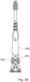
- the Figure 1 shows a front side 66a of an oral hygiene device 10a in a schematic perspective view.
- the oral hygiene device 10a is designed in the present case as a toothbrush, in particular as a children's toothbrush.
- the oral hygiene device 10a can also be designed as a disposable toothbrush or as a replaceable head toothbrush.
- the oral hygiene device 10a could be designed as a flosser, a single-tuft brush, an interdental cleaner, a tongue cleaner or the like.
- Combined oral hygiene products are conceivable that combine at least two different functions, for example a toothbrush with a tongue cleaner, a toothbrush with massage elements, an interdental cleaner with a flosser or the like.
- the oral hygiene product 10a has at least one application unit 12a.
- the oral hygiene product 10a also has at least one handle unit 14a.
- the oral hygiene product 10a has at least one fastening unit 16a with at least one suction cup 18a, which is intended for at least temporary fastening to surfaces, in particular smooth surfaces.
- the suction cup 18a has a cross-section that is different from a circle. In particular, the suction cup 18a is designed differently from a circular suction cup.
- the Figure 2 shows a rear side 68a of the oral hygiene device 10a in a schematic perspective view.
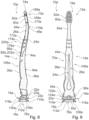
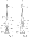
- the Figure 3 shows the front side 66a of the oral hygiene device 10a in a schematic representation.
- the Figure 4 shows a side 70a, in particular a left longitudinal side, of the oral hygiene device 10a in a schematic representation.
- the Figure 5 shows the back 68a of the oral hygiene device 10a in a schematic representation.
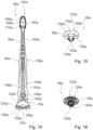
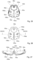
- the Figure 6 shows a bottom side 76a of the oral hygiene device 10a in a schematic representation.
- the Figure 7 shows a top side 74a of the oral hygiene device 10a in a schematic representation.
- the Figure 8 shows a schematic sectional view of the oral hygiene device 10a along the section line VIII-VIII in the Figure 3
- the Figure 9 a schematic sectional view of the oral hygiene device 10a along the section line IX-IX in the Figure 4 .
- the oral hygiene device 10a has a longitudinal axis 28a, a height axis 100a and a width axis 102a (cf. Figures 6 ).
- the longitudinal axis 28a is arranged parallel to a main extension direction of the oral hygiene device 10a. If the oral hygiene device 10a is placed with the back 68a on a flat surface so that the longitudinal axis 28a is arranged parallel to the surface, the height axis 100a is arranged perpendicular to the longitudinal axis 28a and perpendicular to the surface.
- the width axis 102a is perpendicular to the longitudinal axis 28a and perpendicular to the Height axis 100a.
- the oral hygiene device 10a has a length, in particular parallel to the longitudinal axis 28a, of approximately 167 mm. Furthermore, the oral hygiene device 10a has a height, in particular parallel to the height axis 100a, of approximately 19 mm. In addition, the oral hygiene device 10a has a width, in particular parallel to the width axis 102a, of approximately 27 mm.
- the application unit 12a comprises at least one brush head 80a, which in the present case is designed as a toothbrush head.
- the brush head 80a comprises at least one cleaning area 82a, which comprises a plurality of bristle bundles.
- the bristle bundles are not shown. Any suitable bristles can be used as bristles, which can be punched and/or molded on, for example, as described above. Bristle bundles can differ in terms of their length, composition, number of bristles, bristle material, color, surface structure and the like.
- angles at which the bristles and/or the bristle bundles are arranged relative to one another or to a surface of the brush head 80a can vary between bristles and/or between bristle bundles.
- the application unit 12a in the present case comprises at least one neck element 84a, which in particular connects the brush head 80a to the handle unit 14a.
- the application unit 12a is arranged on the top side 74a of the oral hygiene device 10a.
- the application unit 12a forms an uppermost point of the oral hygiene device 10a.
- the application unit 12a is formed partly from a soft component 24a and partly from a hard component 26a.
- the hard component 26a is, for example, a polypropylene (PP).
- the soft component 24a is, for example, a thermoplastic elastomer.
- the brush head 80a and/or the neck element 84a is formed partly from the soft component 24a and partly from the hard component 26a.
- the handle unit 14a has at least one thumb grip area 86a.
- the thumb grip area 86a has at least one thumb grip element 88a.
- the thumb grip element 88a is made of a soft component 24a.
- the thumb grip element 88a is made in one piece.
- the Thumb grip element 88a on a surface of the oral hygiene device 10a is formed as an island of soft component 24a surrounded by hard component 26a.
- the thumb grip element 88a is arranged on the front side 66a of the oral hygiene device 10a.
- the thumb grip element 88a has a plurality of surface structure elements 90a, 92a, of which only some are provided with reference numerals for reasons of clarity.
- the thumb grip element 88a has ten surface structure elements 90a, 92a arranged in pairs.
- the surface structure elements 90a, 92a are formed in the present case as flattened material elevations and in particular have an oval cross-section, although any other geometries are conceivable. Depressions are also conceivable.
- the thumb grip element 88a forms the surface structure elements 90a, 92a.
- the handle unit 14a has at least one handle area 94a.
- the handle area 94a comprises at least one handle element 96a.
- the handle element 96a is arranged on the back 68a of the oral hygiene device 10a.
- the handle element 96a comprises a plurality of surface structure elements 98a, 104a, which are not all provided with reference numerals for reasons of clarity.
- the surface structure elements 98a, 104a are geometrically similar to those of the thumb grip element 88a and in particular are designed analogously to them.
- a size of the surface structure elements 98a, 104a changes along the longitudinal axis 28a, with centrally arranged surface structure elements 98a, 104a being larger than those arranged at the edge.
- the handle area 94a further comprises an entire central section 106a of the oral hygiene device 10a, which can be grasped with one hand, for example, during use. In particular, in a held state, a thumb comes to rest on the thumb grip element 88a, while the insides of the other fingers come to rest on the handle element 96a.
- the oral hygiene device 10a has a plurality of protrusions and indentations distributed along its longitudinal axis 28a.
- the oral hygiene device 10a has, when viewed on its front side 66a, six bulges and five constrictions. Transitions between bulges and constrictions are preferably rounded, but straight transitions are also conceivable.
- the oral hygiene device 10a is slightly curved when viewed from its side 70a, which advantageously results in spring properties of the application unit 12a in a known manner.
- the shape of the oral hygiene device 10a will be adapted by a person skilled in the art in a practical and application-related manner.
- a center of gravity of the oral hygiene device 10a is close to its underside 76a and in particular closer to the underside 76a than to the top 74a, so that a stable stand can be achieved.
- the oral hygiene device 10a is thickened in a lower region of the handle unit 14a and in a region of the fastening unit 16a and/or has the most material there.
- a main extension plane of the suction cup 18a is arranged perpendicular to the longitudinal axis 28a of the oral hygiene device 10a.
- the longitudinal axis 28a of the oral hygiene device 10a runs through a geometric center and/or through a center of gravity of the suction cup 18a.
- the cross section of the suction cup 18a is perpendicular to the longitudinal axis 28a of the oral hygiene device 10a and point-symmetrical to the longitudinal axis 28a of the oral hygiene device 10a.
- the suction cup 18a is arranged on the underside 76a of the oral hygiene device 10a and/or on an underside of the fastening unit 16a.
- the suction cup 18a forms a lowest point of the oral hygiene device 10a.
- the suction cup 18a is formed from the soft component 24a.
- the suction cup 18a is formed in one piece.
- the suction cup 18a is injection-molded.
- the oral hygiene product 10a can be attached to a surface, in particular a smooth surface, by means of the suction cup 18a, wherein the suction cup is advantageously compressed parallel to the longitudinal axis 28a, so that a negative pressure is formed in an interior space 108a of the suction cup 18a.
- the negative pressure then generates a fastening force.
- the suction cup 18a is bell-shaped.
- the suction cup 18a is oval.
- the suction cup 18a is designed as an oval suction cup.
- the suction cup 18a has a cross-section perpendicular to the longitudinal axis 28a that is different from a circle.
- the cross-section is perpendicular to the longitudinal axis 28a, in particular oval.
- the suction cup 18a is ovoid-shaped and in particular ovoid segment-shaped.
- the suction cup 18a has an oval cross-section when viewed from the underside 76a.
- the suction cup 18a has an annular support surface 110a (cf. Figure 6 ).
- the support surface 110a is oval-ring-shaped. In a state attached to a surface, at least the support surface 110a touches the surface.
- parts of an inner side 112a of the suction cup 18a can also touch the surface.
- the suction cup 18a has a width, in particular parallel to the width axis 102a of the oral hygiene device 10a, of approximately 27 mm.
- the suction cup 18a in the present case has a length, in particular parallel to the height axis 100a of the oral hygiene device 10a, of approximately 19 mm.
- the suction cup 18a in the present case has a height, in particular parallel to the longitudinal axis 28a of the oral hygiene device 10a, of approximately 5 mm.
- the specified dimensions of the suction cup 18a relate in particular to its undeformed state.
- the suction cup 18a is at least partially formed as one piece with the handle unit 14a.
- the suction cup 18a is formed as one piece with the handle element 96a and/or with the thumb grip element 88a.
- all elements of the oral hygiene product 10a are manufactured from the soft component 24a in a common injection molding step.
- the oral hygiene product 10a has at least one soft element 44a made from the soft component 24a, which forms at least part of the fastening unit 16a and the handle unit 14a and advantageously the application unit 12a.
- the soft element 44a preferably forms all soft component elements of the oral hygiene product 10a, at least apart from cleaning elements such as bristles of the application unit 12a.
- the fastening unit 16a has at least one disk-shaped carrier element 20a, which is provided in at least one storage state to at least partially prevent deformation of the suction cup 18a.
- the storage state is in particular in the state in which the oral hygiene product 10a is placed on a, in particular smooth and/or flat surface, with its rear side 68a.
- the suction cup is 18a in the deposited state is in contact with the surface without contact or preferably at least only touches it in such a way that it is not deformed or is deformed by less than 10%.
- the carrier element 20a is designed in the present case as a disc that tapers outwards, although a disc of constant thickness is also conceivable.
- the carrier element 20a is designed in the present case as a non-curved disc.
- the carrier element 20a is designed like a surfboard and/or snowboard.
- the carrier element 20a has a rounded and/or curved outer edge 116a that runs in particular around the longitudinal axis 28a of the oral hygiene device 10a.
- the longitudinal axis 28a advantageously runs through a geometric center and/or through a center of gravity of the carrier element 20a.
- cross sections of the carrier element 20a perpendicular to the longitudinal axis 28a of the oral hygiene device 10a are point-symmetrical to the longitudinal axis 28a of the oral hygiene device 10a.
- the carrier element 20a is designed as a stylized surfboard.
- a main extension plane of the carrier element 20a is arranged in the present case parallel to a main extension plane of the suction cup 18a and/or perpendicular to the longitudinal axis 28a of the oral hygiene device 10a.
- the carrier element 20a defines at least one deposit point 22a, with which the oral hygiene product 10a rests in particular on the surface.
- the carrier element 20a has an approximately linear deposit area 114a, which contains the deposit point 22a.
- the deposit area 114a is a rear section of the outer edge 116a of the carrier element 20a.
- the oral hygiene product 10a has a further deposit area 118a, which comprises a rear section of the neck element 84a.
- At least one further deposit point 46a is arranged in the deposit area 118a.
- geometries are also conceivable in which further elements of the oral hygiene product 10a form further deposit areas.
- the oral hygiene product 10a can be deposited on the surface with the deposit area 114a and the further deposit area 118a.
- the carrier element 20a is formed partly from the soft component 24a and partly from the hard component 26a.
- the soft element 44a forms part of the carrier element 20a.
- a section 120a of the carrier element 20a arranged on the back side 68a of the oral hygiene device 10a is made of the Soft component 24a and/or the soft element 44a.
- the section 120a comprises the storage area 114a of the carrier element 20a made of the soft component 24a.
- the carrier element 20a has a thickness of at most 6 mm. In the present case, the carrier element 20a has a thickness of approximately 3 mm. In particular, the carrier element 20a is thicker in the middle than at an edge.
- a cross section of the carrier element 20a in particular perpendicular to the longitudinal axis 28a of the oral hygiene device 10a, is modeled on the cross section of the suction cup 18a, in particular perpendicular to the longitudinal axis 28a of the oral hygiene device 10a, preferably in the undeformed state of the suction cup 18a.
- the carrier element 20a is oval.
- the carrier element 20a has a width, in particular parallel to the width axis 102a of the oral hygiene device 10a, of approximately 27 mm.
- the carrier element 20a has a length, in particular parallel to the height axis 100a of the oral hygiene device 10a, of approximately 19 mm.
- the cross section of the carrier element 20a is geometrically the same as the cross section of the suction cup 18a.
- the carrier element 20a is ovoid-shaped.
- the carrier element 20a is designed in particular as a disk in the form of a flat ovoid.
- the cross section of the carrier element 20a When viewed along the longitudinal axis 28a of the oral hygiene device 10a, the cross section of the carrier element 20a is at least as large as the cross section of the suction cup 18a.
- the cross section of the carrier element 20a when viewed at the underside 76a of the oral hygiene device 10a parallel to the longitudinal axis 28a of the oral hygiene device 10a, the cross section of the carrier element 20a includes the cross section of the suction cup 18a or is identical to it. In the present case, the cross sections are identical.
- the carrier element 20a projects beyond the suction cup 18a at least in sections, in particular on the rear side 68a of the oral hygiene device 10a, preferably at least with the storage area 114a, so that the suction cup 18a is preferably deposited without contact in the storage state.
- the fastening unit 16a preferably the carrier element 20a, defines at least one point 30a of maximum width, in particular maximum width of the oral hygiene device 10a.
- the point 30a of maximum width is along the longitudinal axis 28a of the Oral hygiene device 10a is arranged at a height of the carrier element 20a.
- the suction cup 18a defines a further point of maximum width of the oral hygiene device 10a.
- the fastening unit 16a has at least one passage 32a arranged above the suction cup 18a.
- the passage 32a extends from the rear side 68a to the front side 66a of the oral hygiene device 10a and in particular parallel to the vertical axis 100a of the oral hygiene device 10a.
- the passage 32a is suitable for hanging the oral hygiene device 10a, for example on a hook or a nail.
- the passage 32a is surrounded at least in sections by the soft component 24a.
- the passage 32a is surrounded on an upper side by the soft component 24a and on an underside by the hard component 26a.
- the carrier element 20a in particular its section 130a made of the hard component 26a, delimits the passage 32a towards the suction cup 18a.
- the passage 32a is arranged directly above the carrier element 20a.
- the passage 32a is arranged on a side of the carrier element 20a facing away from the suction cup 18a.
- the passage 32a has a, in particular minimal, width, in particular parallel to the width axis 102a of the oral hygiene device 10a, of at least 4 mm.
- the passage 32a has a, in particular minimal, height, in particular parallel to the height axis 100a of the oral hygiene device 10a, of at least 2 mm.
- a minimum height of the passage 32a is approximately 3 mm and/or a minimum width of the passage 32a is approximately 5 mm.
- the fastening unit 16a has at least one connecting element 34a which at least partially delimits the passage 32a. Furthermore, the fastening unit 16a in the present case has at least one further connecting element 36a which at least partially delimits the passage 32a.
- the connecting elements 34a are in the present case mirror-symmetrical to one another.
- the connecting elements 34a, 36a connect the carrier element 20a to the handle unit 14a.
- the connecting elements 34a, 36a are connected to one another above the passage 32a and in particular form an arcuate upper side of the passage 32a.
- the connecting elements 34a, 36a are in the present case at least partially formed in one piece with one another.
- the connecting elements 34a, 36a and the support elements 20a together form the passage 32a and/or together completely surround it.
- the connecting element 34a is formed at least in sections by the hard component 26a, which is penetrated by the soft component 24a.
- the soft component 24a penetrates the hard component 26a of the connecting element 34a in the form of two penetrations 122a, 124a, in particular from the rear side 68a to the front side 66a of the oral hygiene device 10a.
- the penetrations 122a, 124a are in particular formed as through holes in the hard component 26a filled with the soft component 24a.
- a different number of penetrations 122a, 124a is conceivable.
- the same structure also applies to the connecting element 36a.
- the connecting elements 34a, 36a are designed as stylized legs, in particular as animal legs, which preferably stand with feet and/or paws on the carrier element 20a.
- the connecting elements 34a, 36a Through the penetrations 122a, 124a, islands 126a, 128a made of soft component 24a are formed on a front surface of the connecting elements 34a, 36a, which in particular form stylized claws and/or toenails.
- the islands 126a, 128a on a surface of the oral hygiene device 10a are in contact with other elements made of soft component 24a, in particular in contact with the section 120a made of soft component 24a of the carrier element 20a.
- the islands 126a, 128a are formed integrally with other elements made of soft component 24a through an interior of the oral hygiene device 10a, in particular the fastening unit 16a.
- the soft element 44a forms the islands 126a, 128a.
- the soft element 44a is intended to form all existing deposition points 22a, 46a in the deposited state. In the deposited state, the oral hygiene product 10a rests exclusively on the soft element 44a.
- the soft element 44a extends on the back 68a of the oral hygiene device 10a without interruption from the fastening unit 16a via the handle unit 14a to the application unit 12a.
- the soft element 44a extends from the suction cup 18a via the carrier element 20a, the connecting elements 34a, 36a, the handle element 96a and the neck element 84a to a rear side of the brush head 80a.
- the soft element 44a has a single injection point 50a.
- the injection point 50a is arranged on the back 68a of the oral hygiene device 10a.
- the injection point 50a is arranged in a region above the connecting elements 34a, 36a and/or below the handle element 96a.
- the soft element 44a forms elements 172a, 174a, 176a in at least one region 200a between the neck element 84a of the application unit 12a and a handle element 202a, in the present case the thumb handle element 88a, which are at least partially supplied with the soft component 24a from the rear side 68a.
- the elements 172a, 174a, 176a are decorative elements.
- the elements 172a, 174a, 176a are supplied with the soft component 24a from the rear side 68a during the manufacture of the oral hygiene product 10a.
- the oral hygiene product 10a has at least one, in particular exactly one, base body 38a made of the hard component 26a, which forms at least part of the fastening unit 16a, the handle unit 14a and the application unit 12a.
- the base body 38a forms all of the hard component elements of the oral hygiene product 10a, at least apart from any cleaning elements of the application unit 12a.
- the base body 38a forms a, in particular supporting, section 130a made of hard component 26a of the carrier element 20a, onto which the suction cup 18a is advantageously molded.
- the Figure 10 shows a front side 132a of the base body 38a in a schematic perspective view.
- the Figure 11 shows a rear side 134a of the base body 38a in a schematic perspective view.
- the Figure 12 shows the front side 132a of the base body 38a in a schematic representation.
- the Figure 13 shows a side 136a, in particular a left longitudinal side, of the base body 38a in a schematic representation.
- the Figure 14 shows the rear side 134a of the base body 38a in a schematic representation.
- the Figure 15 shows a bottom side 138a of the base body 38a in a schematic representation.
- the Figure 16 shows a top side 140a of the base body 38a in a schematic representation.
- the Figure 17 shows a schematic sectional view of the base body 38a along the section line XVII-XVII in the Figure 12
- the Figure 18 a schematic sectional view of the base body 38a along the section line XVIII-XVIII in the Figure 13 .
- the base body 38a forms at least one carrier structure 40a arranged above the fastening unit 16a, onto which at least one motif element 42a is formed, which is overmolded with soft component 24a through the carrier structure 40a (see also the Figures 1 to 9 ).
- the motif element 42a is formed from the hard component 26a.
- the motif element 42a is placed on the carrier structure 40a.
- the base body 38a has a central opening 142a, which is arranged on the rear side 134a of the base body 38a and at least partially breaks through to the front side 132a of the base body 38a.
- the soft component 24a passes from its injection point 50a through, among other things, the central opening 142a from the rear side 134a to the front side 132a of the base body 38a.
- the motif element 42a spans the central opening 142a.
- the central opening 142a is at least partially arranged in a region of the carrier structure 40a.
- the support structure 40a forms lateral side walls 144a, 146a of the central opening 142a at least in sections.
- the central opening 142a is designed in a sword-like manner in sections.
- the central opening 142a comprises a bulbous, in particular double-bulbous, widening 148a in an area of the fastening unit 16a.
- the motif element 42a is arranged in particular on a front side of the widening 148a of the central opening 142a and is preferably supplied with soft component 24a through this.
- the support structure 40a forms a border of the widening 148a of the central opening 142a.
- the soft component 24a During the injection molding of the soft component 24a, it flows in particular via at least two different paths to an area of the suction cup 18a in order to form it.
- the soft component 24a passes from the rear side 134a of the base body 38a along the connecting elements 34a and 36a to a rear side of the suction cup 18a from where the entire suction cup 18a is supplied.
- the motif element 42a is advantageously supplied with soft component 24a through the central opening 142a and outside around the support structure 40a in order to form the motif 150a.
- the motif element 42a together with its overmold, forms, among other things, a motif 150a of the oral hygiene product 10a.
- the motif 150a is a stylized cat, which in particular stands on the carrier element 20a.
- the motif 150a further comprises two arm elements 152a, 154a, which have stylized arms and/or front legs, advantageously with paws, which comprise claws or the like made of the soft component 24a.
- the motif 150a further comprises the connecting elements 34a, 36a, which, as mentioned, form stylized legs.
- the support structure 40a and in particular the arm elements 152a, 154a and/or the connecting elements 34a, 36a can be combined unchanged with different motif elements 42a, so that only for the hard component 26a different injection molds are required, which further only differ with regard to the motif element 42a.
- the base body 38a has a single injection point 160a.
- the injection point 160a of the base body 38a is overmolded with the soft component 24a.
- the injection point 160a of the base body 38a is arranged in a region of the injection point 50a of the soft element 44a and is preferably less than 10 mm away from it.
- the base body 38a forms two support elements 156a, 158a formed on the carrier element 20a.
- the support elements 156a, 158a are ramp-shaped.
- the support elements 156a, 158a are arranged on the underside 138a of the base body 38a.
- the support elements 156a, 158a are provided to form support points when the base body 38a is ejected after its injection molding.
- the support elements 156a, 158a are overmolded with the soft component 24a and in particular within the suction cup 18a, within the carrier element 20a and/or within a connecting region between the suction cup 18a and the carrier element 20a.
- the base body 38a also forms at least one web element 162a of the carrier element 20a.
- the web element 162a extends from the front side 132a towards the rear side 134a of the base body 38a in a central area of the carrier element 20a.
- the web element 162a forms a rearmost point of the section 130a made of hard component 26a of the carrier element 20a.
- the web element 162a forms at least in sections a surface of the carrier element 20a and/or a lower boundary of the passage 32a (see also the Figures 1 to 9 ).
- a fastening region of the suction cup 18a on the carrier element 20a is arranged below the web element 162a, so that the suction cup 18a is advantageously stabilized by the web element 162a, for example when pressed.
- the web element 162a is provided for stabilizing the suction cup 18a during its production by injection molding.
- the base body 38a further has at least one channel 164a, which is arranged in a region of the neck element 84a of the application unit 12a.
- the channel 164a extends from the central opening 142a along the neck element 84a to the brush head 80a.
- the soft component 24a is fed to the brush head 80a, in particular its rear side, through the channel 164a.
- the soft component 24a passes through the channel 164a to the decorative elements 172a, 174a, 176a arranged above the thumb grip element 88a, which are each formed partly from the hard component 26a and partly from the soft component 24a (cf. Figures 1 to 9 ).
- the brush head 80a has three support elements 166a, 168a, 170a.
- the support elements 166a, 168a, 170a are arranged on a rear side of the brush head 80a and, in an overmolded state, form part of a rear surface of the brush head 80a.
- the support elements 166a, 168a, 170a are provided for supporting the oral hygiene product 10a and for ejecting it during its manufacture.
- the support elements 166a, 168a, 170a are provided for supporting the brush head 80a when the bristle bundles are punched.
- a different number of support elements 166a, 168a, 170a is also conceivable, for example one or two or four or five or even more.
- the base body 38a is wavy on its rear side 134a in an area of the brush head 80a. In the present case, however, a corresponding wavy area is overmolded with the soft component 24a and preferably smoothed so that it is no longer visible in the end product.
- the Figure 19 shows a system 64a with the oral hygiene product 10a and with a protective cap 62a in a schematic perspective view.
- the protective cap 62a is an oral hygiene product protective cap.
- the protective cap 62a is designed as a toothbrush protective cap, which is preferably intended to be placed on a single toothbrush.
- the protective cap 62a can also be designed differently.
- it can be designed as a protective cap for a flosser, a tongue cleaner, a single-tuft brush, an interdental cleaner or the like.
- the protective cap has a cap body 52a, which defines at least one interior space 54a, which is intended to accommodate at least part of the oral hygiene product 10a (see Figure 24 ).
- the interior space 54a is provided for receiving at least a part of the application unit 12a and in particular for receiving the brush head 80a.
- the cap body 52a has at least one hanger 56a.
- the Figure 20 shows the protective cap 62a in a schematic perspective view.
- the Figure 21 shows a front side 186a of the protective cap 62a in a schematic representation.
- the Figure 22 shows a side 188a, in particular a left longitudinal side, of the protective cap 62a in a schematic representation.
- the Figure 23 shows a rear side 190a of the protective cap 62a in a schematic representation.
- the Figure 24 shows the oral hygiene device 10a with a shell element 60a of the protective cap 62a in a schematic side view.
- the Figure 25 shows an inner side 192a of the protective cap 62a in an opened state of the protective cap 62a in a schematic representation.
- the Figure 26 shows an outer side 194a of the protective cap 62a in the opened state in a schematic representation.
- the Figure 27 the protective cap 62a in the opened state in a schematic sectional view along the section line XXVII-XXVII in the Figure 26 .
- the hanger 56a is hook-shaped.
- the hanger 56a is designed as a U-shaped hook.
- the hanger 56a is curved by at least 150°, advantageously by at least 170°.
- the hanger 56a is arranged above the brush head 80a of the oral hygiene product 10a.
- the oral hygiene product 10a can be hung on the hanger 56a when the protective cap 62a is in place, for example on a hook, a rod, an eyelet, a handle, a cord or the like.
- other types of hangers are also conceivable, for example magnetic hangers, hangers with suction cups, hangers with Velcro material, hangers with an eyelet or the like.
- the hanger 56a is designed as a hollow body.
- An interior space 178a of the hanger 56a is connected to the interior space 54a of the cap body 52a.
- the hanger 56a is molded directly onto the interior space 54a.
- the interior space 54a of the cap body 52a and the interior space 178a of the hanger have walls formed as one piece.
- the cap body 52a is formed in one piece.
- the protective cap 62a is formed in one piece.
- the protective cap 62a has exactly the cap body 52a.
- the cap body 52a forms the protective cap 62a.
- a protective cap 62a has additional elements apart from a cap body 52a.
- the cap body 52a in the present case is formed completely from a hard component 180a, in particular from propylene, whereby any hard components are conceivable.
- the cap body 52a has elements made of a soft component, for example sealing elements and/or support elements, in particular in an area of the hanger 56a.
- the cap body 52a has a length of approximately 50 mm and/or a width of approximately 25 mm and/or a height of approximately 25 mm.
- the cap body 52a has a wall thickness of approximately 1 mm.
- the wall thickness of the cap body 52a is constant, at least in an area of the hanger 56a and/or in an area of the interior 54a.
- the cap body 52a has at least two shell elements 58a, 60a, in particular at least one first shell element 58a and at least one second shell element 60a, which are connected to one another in an articulated manner and each form a part of the hanger 56a.
- the cap body 52a In the attached state, the cap body 52a is in particular in a closed state.
- the shell elements 58a, 60a form mirror-symmetrical halves of the hanger 56a.
- the halves of the hanger 56a lie directly on top of one another when the cap body 52a is in a closed state.
- a hanger 56a is formed by and/or attached to only one single shell element 58a, 60a.
- the cap body 52a has a passage 182a through which the neck element 84a of the oral hygiene product 10a enters the interior 54a of the cap body 52a when it is in place.
- a cross section of the passage 182a is adapted to a cross section of the neck element 84a, whereby a certain amount of play can be provided.
- the passage 182a is dimensioned such that pulling the brush head 80a out of the interior 54a through the passage 182a is impossible when it is closed.
- the passage 182a rests on bristles 184a of the brush head 80a and/or on its bristle carrier.
- the shell elements 58a, 60a together form the passage 182a.
- the passage 182a is opened so that it can be placed against the neck element 84a and when the cap body 52a is closed, it wraps around the neck element 84a.
- the interior 54a closes around the brush head 80a.
- the cap body 52a has a film hinge 196a, which connects the shell elements 58a, 60a to one another in an articulated manner.
- the cap body 52a has a single film hinge 196a.
- the hanger 56a is in particular free of a film hinge 196a.
- the film hinge 196a is arranged on the back 190a of the protective cap 62a.
- the cap body 52a has at least one ventilation hole 198a.
- the cap body 52a has a plurality of ventilation holes 198a, of which only one is provided with a reference number for reasons of clarity.
- the shell elements 58a, 60a each have at least one ventilation hole 198a and advantageously several ventilation holes 198a.
- an arrangement of ventilation holes 198a of the first shell element 58a is mirror-symmetrical to an arrangement of ventilation holes 198a of the second shell element 60a.
- the ventilation holes are advantageously arranged on lateral sides 188a of the protective cap 62a and in particular not on its front side 186a and/or on its back side 190a.
- the ventilation holes 198a are designed such that they form a stylized face.
- the ventilation holes 198a form, for example, a stylized mouth and/or stylized eyes and/or stylized nostrils.
- the protective cap 62a advantageously forms a stylized face.
- the Figure 28 shows a front side 66b of a first alternative oral hygiene device 10b in a schematic representation.
- the Figure 29 shows a rear side 68b of the first alternative oral hygiene device 10b in a schematic representation.
- the Figure 30 shows a base body 38b of the first alternative oral hygiene product 10b in a schematic representation.
- the first alternative oral hygiene product 10b has a Application unit 12b, a handle unit 14b and a fastening unit 16b.
- the fastening unit 16b has at least one suction cup 18b and is intended for at least temporary fastening to surfaces.
- the suction cup 18b has a cross-section other than a circle. In particular, the suction cup 18b is oval.
- the fastening unit 16b has at least one disk-shaped carrier element 20b, which in at least one storage state is intended to at least partially prevent deformation of the suction cup 18b.
- the carrier element 20b is arranged directly above the suction cup 18b.
- the base body 38b forms at least one carrier structure 40b arranged above the fastening unit 16b, onto which at least one motif element 42b is formed, which is overmolded with soft component 24b through the carrier structure 40b.
- the overmolded motif element 42b forms part of a motif 150b.
- the motif 150b is designed as a stylized beaver that stands on the carrier element 20b.
- the motif 150b differs from that of the embodiment of the Figures 1 to 27 only by the motif element 42b, whereas other components such as in particular stylized legs and arms are identically designed.
- the handle unit 14b has a thumb grip element 88b and a hand grip element 96b with surface structure elements 90b, 92b, 98b, 104b, which differ from those of the embodiment of the Figures 1 to 27 with regard to a cross-section.
- the surface structure elements 90b, 92b, 98b, 104b each have base areas with a semicircular section and with an adjacent trapezoidal and/or rectangular section.
- the Figure 31 shows a front side 66c of a second alternative oral hygiene device 10c in a schematic representation.
- the Figure 32 shows a rear side 68c of the second alternative oral hygiene device 10c in a schematic representation.
- the Figure 33 shows a base body 38c of the second alternative oral hygiene device 10c in a schematic representation.
- the second alternative oral hygiene device 10c has an application unit 12c, a handle unit 14c and a fastening unit 16c.
- the fastening unit 16c has at least one suction cup 18c and is intended for at least temporary fastening to surfaces.
- the suction cup 18c has a cross-section other than a circle. In particular, the suction cup 18c is oval.
- the fastening unit 16c has at least one disk-shaped carrier element 20c, which is provided in at least one storage state to at least partially prevent deformation of the suction cup 18c.
- the carrier element 20c is arranged directly above the suction cup 18c.
- the base body 38c forms at least one carrier structure 40c arranged above the fastening unit 16c, onto which at least one motif element 42c is formed, which is overmolded with soft component 24c through the carrier structure 40c.
- the overmolded motif element 42c forms part of a motif 150c.
- the motif 150c is designed as a stylized dog standing on the carrier element 20c.
- the motif 150c differs from those of the embodiments of the Figures 1 to 30 only by the motif element 42c, whereas other components such as in particular stylized legs and arms are identically designed.
- the handle unit 14c has a thumb grip element 88c and a hand grip element 96c with surface structure elements 90c, 92c, 98c, 104c, which differ from those of the embodiments of the Figures 1 to 30 with respect to a cross-section.
- the surface structure elements 90c, 92c, 98c, 104c each have circular bases.
- the Figure 34 shows a front side 66d of a third alternative oral hygiene device 10d in a schematic representation.
- the Figure 35 shows a rear side 68d of the third alternative oral hygiene device 10d in a schematic representation.
- the Figure 36 shows a base body 38d of the third alternative oral hygiene device 10d in a schematic representation.
- the third alternative oral hygiene device 10d has an application unit 12d, a handle unit 14d and a fastening unit 16d.
- the fastening unit 16d has at least one suction cup 18d and is intended for at least temporary fastening to surfaces.
- the suction cup 18d has a cross-section other than a circle. In particular, the suction cup 18d is oval.
- the fastening unit 16d has at least one disk-shaped carrier element 20d, which in at least one storage state is intended to at least partially prevent deformation of the suction cup 18d.
- the carrier element 20d is arranged directly above the suction cup 18d.
- the base body 38d forms at least one carrier structure 40d arranged above the fastening unit 16d, onto which at least one motif element 42d is formed, which is overmolded with soft component 24d through the carrier structure 40d.
- the overmolded motif element 42d forms part of a motif 150d.
- the motif 150d is designed as a stylized alligator standing on the carrier element 20d.
- the motif 150d differs from those of the embodiments of the Figures 1 to 33 only by the motif element 42d, whereas other components such as in particular stylized legs and arms are identically designed.
- the handle unit 14d has a thumb grip element 88d and a hand grip element 96d with surface structure elements 90d, 92d, 98d, 104d, which differ from those of the embodiments of the Figures 1 to 33 with respect to a cross-section.
- the surface structure elements 90d, 92d, 98d, 104d each have triangular bases.
Landscapes
- Brushes (AREA)
Description
- Die Erfindung betrifft ein Mundhygienemittel nach dem Oberbegriff des Anspruchs 1 und eine Schutzkappe für ein Mundhygienemittel nach dem Oberbegriff des Anspruchs 22. Mundhygienemittel mit saugnapfähnlichen Teilen sind bereits aus der
CH 584 545 A5 EP 0 611 533B2 , derEP 0 960 284 B1 , derUS 2002/0100134 A1 , derUS 9 521 899 B1 WO 94/20006 A1 - Die Aufgabe der Erfindung besteht insbesondere darin, vorteilhafte Eigenschaften hinsichtlich einer sicheren und/oder hygienischen Verwahrung und/oder einer kostengünstigen Herstellbarkeit und/oder einer ergonomischen Ausgestaltung zu erzielen. Die Aufgabe wird erfindungsgemäß durch die Merkmale der unabhängigen Ansprüche gelöst, während vorteilhafte Ausgestaltungen und Weiterbildungen der Erfindung den Unteransprüchen entnommen werden können.
- Die Erfindung ist durch die unabhängigen Ansprüche definiert. Die Erfindung geht aus von einem Mundhygienemittel, insbesondere einer Zahnbürste, mit zumindest einer Anwendungseinheit, mit zumindest einer Griffeinheit und mit zumindest einer Befestigungseinheit, die zumindest einen Saugnapf aufweist und zu einer zumindest temporären Befestigung an Oberflächen vorgesehen ist.
- Durch die erfindungsgemäße Ausgestaltung des Mundhygienemittels können vorteilhafte Eigenschaften hinsichtlich einer sicheren und/oder hygienischen Befestigung und/oder Lagerung erzielt werden. Insbesondere kann eine hohe Befestigungskraft erzielt werden. Außerdem kann das Mundhygienemittel vorteilhaft einfach abgelegt werden, ohne dass der Saugnapf an Befestigungskraft einbüßt, beispielsweise aufgrund einer unerwünschten Verformung desselben. Weiterhin kann der Saugnapf bei einem Transport des Mundhygienemittels, etwa während der Herstellung, beim Nutzer in einer Tasche oder einem Etui oder einem Necessaire oder dergleichen, vorteilhaft vor Beschädigungen geschützt werden. Ferner kann ein Mundhygienemittel mit einem kompakten Befestigungsbereich, der zugleich eine Erzeugung einer hohen Kraft ermöglicht, bereitgestellt werden. Zudem kann eine Befestigung, beispielsweise bei einem Anheften an eine Oberfläche, erzielt werden, deren versehentliches Lösen aufgrund einer hohen Haltekraft vermieden wird, die aber insbesondere dennoch komfortabel gezielt lösbar ist, insbesondere aufgrund einer Form des Saugnapfs. Außerdem kann ein Saugnapf mit einer großen Fläche bereitgestellt werden, der zugleich eine kompakte Bauweise eines Handgriffs erlaubt. Weiterhin kann eine kostengünstige Herstellbarkeit erzielt werden. Insbesondere kann ein Mundhygienemittel mit einer Befestigungsfunktion bereitgestellt werden, dessen Hauptkörper in einem einzelnen Spritzgussprozess vorteilhaft kostengünstig herstellbar ist.
- Unter einem "Mundhygienemittel" soll insbesondere eine Zahnbürste und/oder ein Interdentalreiniger und/oder ein Flosser und/oder ein Zungenreiniger und/oder ein Zahnstocher verstanden werden. Erfindungsgemäß ist das Mundhygienemittel als eine Zahnbürste, insbesondere eine Handzahnbürste, bevorzugt eine Kinderzahnbürste, vorteilhaft eine rein manuelle oder eine teilelektrische beziehungsweise hybride Zahnbürste, beispielsweise mit Vibrationsfunktion oder dergleichen, ausgebildet. Insbesondere ist das Mundhygienemittel von einer vollelektrischen Zahnbürste verschieden. Das Mundhygienemittel kann hierbei eine Einwegzahnbürste, eine Mehrwegzahnbürste oder auch eine Wechselkopfzahnbürste sein. Das Mundhygienemittel weist insbesondere eine Längsachse auf, die vorteilhaft zumindest im Wesentlichen parallel zu einer Haupterstreckungsrichtung des Mundhygienemittels angeordnet ist. Bevorzugt verläuft die Längsachse zumindest abschnittsweise innerhalb des Mundhygienemittels und insbesondere durch dessen Schwerpunkt. Insbesondere ist die Längsachse des Mundhygienemittels eine Zentralachse des Mundhygienemittels und/oder eine Zentralachse der Griffeinheit. Unter einer "Zentralachse" eines Objekts soll dabei insbesondere eine gedachte Achse verstanden werden, die innerhalb des Objekts parallel zu einer Haupterstreckungsrichtung des Objekts verläuft und das Objekt an höchstens zwei Punkten schneidet. Unter "zumindest im Wesentlichen parallel" soll hier insbesondere eine Ausrichtung einer Richtung relativ zu einer Bezugsrichtung, insbesondere in einer Ebene, verstanden werden, wobei die Richtung gegenüber der Bezugsrichtung eine Abweichung insbesondere kleiner als 8°, vorteilhaft kleiner als 5° und besonders vorteilhaft kleiner als 2° aufweist. Unter einer "Haupterstreckungsrichtung" eines Objekts soll dabei insbesondere eine Richtung verstanden werden, welche parallel zu einer längsten Kante eines kleinsten gedachten Quaders verläuft, welcher das Objekt gerade noch vollständig umschließt.
- Insbesondere weist das Mundhygienemittel eine Länge, insbesondere parallel zu der Längsachse des Mundhygienemittels, von wenigstens 110 mm, vorteilhaft von wenigstens 130 mm und besonders vorteilhaft von wenigstens 150 mm und/oder von höchstens 200 mm, vorteilhaft von höchstens 190 mm und besonders vorteilhaft von höchstens 180 mm auf, wobei selbstverständlich auch andere, insbesondere kleinere oder größere, Längen denkbar sind. Insbesondere weist das Mundhygienemittel eine Breite, insbesondere parallel zu einer Breitenachse des Mundhygienemittels, vorteilhaft senkrecht zu der Längsachse und/oder parallel zu einer Haupterstreckungsebene des Mundhygienemittels und/oder der Griffeinheit, von wenigstens 15 mm, vorteilhaft von wenigstens 20 mm und besonders vorteilhaft von wenigstens 23 mm und/oder von höchstens 40 mm, vorteilhaft von höchstens 35 mm und besonders vorteilhaft von höchstens 31 mm auf. Insbesondere weist das Mundhygienemittel eine Höhe, insbesondere gemessen parallel zu einer Höhenachse des Mundhygienemittels, vorteilhaft gemessen senkrecht zu der Längsachse des Mundhygienemittels und/oder senkrecht zu der Haupterstreckungsebene des Mundhygienemittels von wenigstens 10 mm, vorteilhaft von wenigstens 12 mm und besonders vorteilhaft von wenigstens 15 mm und/oder von höchstens 30 mm, vorteilhaft von höchstens 26 mm und besonders vorteilhaft von höchstens 23 mm auf. Der Begriff "Höhe" bezieht sich hierbei insbesondere auf einen Zustand des Mundhygienemittels, in welchem dieses, beispielsweise auf einer Oberfläche wie einer Tischplatte, einem Waschbecken, einer Möbeloberseite oder dergleichen, abgelegt ist, insbesondere derart, dass die Längsachse parallel zu der Oberfläche angeordnet ist. Unter einer "Haupterstreckungsebene" eines Objekts soll insbesondere eine Ebene verstanden werden, welche parallel zu einer größten Seitenfläche eines kleinsten gedachten Quaders ist, welcher das Objekt gerade noch vollständig umschließt, und insbesondere durch den Mittelpunkt des Quaders verläuft.
- Vorteilhaft weist die Anwendungseinheit zumindest einen Reinigungsbereich auf, der zu einer Zahnreinigungsanwendung, insbesondere in einem Mundraum des Benutzers, vorgesehen ist. Vorzugsweise umfasst der Reinigungsbereich zumindest ein Reinigungselement, insbesondere zumindest einen Bürstenkopf, vorteilhaft einen Zahnbürstenkopf, bevorzugt mit mehreren Borsten und/oder Borstenbündeln. Das Reinigungselement kann jedoch beispielsweise auch als eine Interdentalbürste und/oder als ein Single Tuft (z.B. einzelnes großes Borstenbündel) und/oder als ein mit Zahnseide bespannter Bogen, insbesondere als ein Flosser, oder dergleichen ausgebildet sein. Ferner weist die Anwendungseinheit vorteilhaft zumindest ein Halselement auf, welches bevorzugt mit dem Reinigungselement, insbesondere unmittelbar und/oder einstückig verbunden ist. Unter "einstückig" soll insbesondere zumindest stoffschlüssig verbunden, beispielsweise durch einen Schweißprozess, einen Klebeprozess, einen Anspritzprozess und/oder einen anderen, dem Fachmann als sinnvoll erscheinenden Prozess, und/oder vorteilhaft in einem Stück geformt verstanden werden, wie beispielsweise durch eine Herstellung aus einem Guss und/oder durch eine Herstellung in einem Ein- oder Mehrkomponentenspritzverfahren und vorteilhaft aus einem einzelnen Rohling. Unter "vorgesehen" soll insbesondere speziell ausgelegt und/oder ausgestattet verstanden werden. Darunter, dass ein Objekt zu einer bestimmten Funktion vorgesehen ist, soll insbesondere verstanden werden, dass das Objekt diese bestimmte Funktion in zumindest einem Anwendungs- und/oder Betriebszustand erfüllt und/oder ausführt.
- Das Mundhygienemittel weist insbesondere eine Vorderseite und eine Rückseite auf, die insbesondere einander abgewandt angeordnet sind. Vorzugsweise ist der Reinigungsbereich auf der Vorderseite des Mundhygienemittels angeordnet. Die Vorderseite ist insbesondere eine in einer Betrachtungsrichtung senkrecht zu der Längsachse des Mundhygienemittels und senkrecht zu der Breitenachse des Mundhygienemittels sichtbare Seite des Mundhygienemittels. Die Rückseite entspricht vorteilhaft einer in einer hierzu entgegengesetzten Betrachtungsrichtung sichtbaren Seite des Mundhygienemittels. Ferner weist das Mundhygienemittel insbesondere eine Unterseite auf, an welcher vorteilhaft der Saugnapf angeordnet ist. Zudem weist das Mundhygienemittel insbesondere eine, vorteilhaft der Unterseite gegenüberliegend angeordnete, Oberseite auf. Die Anwendungseinheit ist vorzugsweise bezüglich der Längsachse des Mundhygienemittels der Befestigungseinheit gegenüberliegend angeordnet.
- Vorzugsweise weist die Griffeinheit zumindest ein Griffelement auf, das vorteilhaft zu einem Halten mit einer Hand, insbesondere mit einer Kinderhand, vorgesehen ist. Bevorzugt ist das Griffelement, insbesondere mehrfach, tailliert ausgebildet. Dies erlaubt vorteilhaft einen sicheren Halt und optimiert die Ergonomie. Besonders bevorzugt ist das Griffelement länglich ausgebildet, wobei vorteilhaft eine Längsachse des Griffelements der Längsachse des Mundhygienemittels entspricht. Das Griffelement ist vorteilhaft teilweise aus einer Weichkomponente und teilweise aus einer Hartkomponente ausgebildet. Insbesondere umfasst das Griffelement vorteilhaft zumindest einen Daumengriffbereich und/oder zumindest einen Handgriffbereich. Vorteilhaft ist der Daumengriffbereich auf der Vorderseite des Mundhygienemittels und insbesondere auf einer Vorderseite des Griffelements angeordnet. Es ist denkbar, dass der Daumengriffbereich und/oder der Handgriffbereich zumindest ein Element und/oder eine Oberflächenstrukturierung aus einer Weichkomponente aufweisen.
- Vorteilhaft umfasst der Daumengriffbereich zumindest ein Daumengriffelement, welches vorzugsweise aus Weichkomponente und insbesondere an einer Oberfläche des Mundhygienemittels als eine von Hartkomponente umgebene Insel aus Weichkomponente ausgebildet ist. Vorteilhaft bildet das Daumengriffelement zumindest ein Oberflächenstrukturelement aus, insbesondere eine Mehrzahl von, vorteilhaft regelmäßig angeordneten, Oberflächenstrukturelementen, wodurch insbesondere eine vorteilhafte Griffigkeit erzielt werden kann. Ein Oberflächenstrukturelement ist hierbei vorteilhaft als eine Erhebung, insbesondere mit ebener Oberfläche und/oder mit geraden Seitenwänden, ausgebildet. Alternativ ist auch denkbar, dass ein Oberflächenstrukturelement sich zu einer Oberseite hin, insbesondere konisch, verjüngt. Oberflächenstrukturelemente können beispielsweise zylinderförmig, pyramidenförmig, kugelsegmentförmig, insbesondere halbkugelförmig, ovoidsegmentförmig oder dergleichen mehr sein. Ein Querschnitt eines Oberflächenstrukturelements kann hierbei aus unterschiedlichen geometrischen Figuren zusammengesetzt sein, beispielsweise aus einem Halbkreis und einem angrenzenden Rechteck. Ebenso sind polygonale, insbesondere dreieckige, viereckige, fünfeckige oder, sechseckige, Querschnitte denkbar. Ferner sind beliebige Freiform-Figuren denkbar. Vorzugsweise sind die Oberflächenstrukturelemente des Daumengriffelements zumindest im Wesentlichen identisch zueinander oder zumindest geometrisch ähnlich ausgebildet.
- Insbesondere weist das Daumengriffelement eine Länge, insbesondere zumindest im Wesentlichen parallel zu der Längsachse des Mundhygienemittels, von wenigstens 3 mm, vorteilhaft von wenigstens 5 mm und besonders vorteilhaft von wenigstens 10 mm und/oder von höchstens 30 mm, vorteilhaft von höchstens 25 mm und besonders vorteilhaft von höchstens 18 mm auf. Insbesondere weist das Daumengriffelement eine Breite, insbesondere zumindest im Wesentlichen senkrecht zu der Längsachse des Mundhygienemittels, von wenigstens 3 mm, vorteilhaft von wenigstens 4 mm und besonders vorteilhaft von wenigstens 6 mm und/oder von höchstens 15 mm, vorteilhaft von höchstens 12 mm und besonders vorteilhaft von höchstens 10 mm auf. Ein einzelnes Oberflächenstrukturelement weist insbesondere eine Höhe, insbesondere senkrecht zu einer umliegenden Oberfläche des Daumengriffelements, von wenigstens 0,1 mm, vorteilhaft von wenigstens 0,2 mm und besonders vorteilhaft von wenigstens 0,5 mm und/oder von höchstens 2 mm, vorteilhaft von höchstens 1,4 mm und besonders vorteilhaft von höchstens 1 mm auf. Ferner weist ein einzelnes Oberflächenstrukturelement insbesondere eine Länge, insbesondere zumindest im Wesentlichen senkrecht zu der Längsachse des Mundhygienemittels, von wenigstens 0,7 mm, vorteilhaft von wenigstens 1 mm und besonders vorteilhaft von wenigstens 1,5 mm und/oder von höchstens 6 mm, vorteilhaft von höchstens 5 mm und besonders vorteilhaft von höchstens 4 mm auf. Zudem weist ein einzelnes Oberflächenstrukturelement insbesondere eine Breite, insbesondere zumindest im Wesentlichen parallel zu der Längsachse des Mundhygienemittels, von wenigstens 0,3 mm, vorteilhaft von wenigstens 0,5 mm und besonders vorteilhaft von wenigstens 1 mm und/oder von höchstens 5 mm, vorteilhaft von höchstens 4 mm und besonders vorteilhaft von höchstens 3 mm auf.
- Vorzugsweise ist eine Haupterstreckungsrichtung eines Oberflächenstrukturelements hierbei jeweils zumindest im Wesentlichen senkrecht zu einer Haupterstreckungsrichtung des Daumengriffelements angeordnet. Ferner ist vorteilhaft die Haupterstreckungsrichtung des Daumengriffelements zumindest im Wesentlichen parallel zu der Längsachse des Mundhygienemittels angeordnet. Vorteilhaft sind entlang der Längsachse des Mundhygienemittels und/oder quer dazu zumindest zwei Oberflächenstrukturelemente nebeneinander angeordnet. Vorzugsweise sind in Längsrichtung zumindest drei, vorteilhaft zumindest vier und besonders vorteilhaft zumindest fünf Oberflächenstrukturelemente, bevorzugt jeweils quer zu der Längsachse des Mundhygienemittels mit wenigstens einem weiteren, insbesondere spiegelsymmetrisch bezüglich der Längsachse des Mundhygienemittels ausgebildeten, Oberflächenstrukturelement gepaart, nebeneinander, insbesondere in regelmäßigen Abständen, die bevorzugt kleiner sind als eine Breite eines einzelnen Oberflächenstrukturelements, angeordnet, wobei bevorzugt eine Breite und/oder eine Länge von mittig angeordneten Oberflächenstrukturelementen größer ist als eine Breite und/oder Länge von randständigen Oberflächenstrukturelementen und die Breite und/oder Länge besonders bevorzugt zur Mitte des Daumengriffelements hin mit jedem Oberflächenstrukturelement zunimmt. Unter "zumindest im Wesentlichen identischen" Objekten sollen insbesondere Objekte verstanden werden, die derart konstruiert sind, dass sie jeweils eine gemeinsame Funktion erfüllen können und sich vorzugsweise in ihrer Konstruktion abgesehen von Fertigungstoleranzen höchstens durch einzelne Elemente unterscheiden, die für die gemeinsame Funktion unwesentlich sind, und vorteilhaft Objekte, die abgesehen von Maßen, und besonders vorteilhaft zumindest abgesehen von Fertigungstoleranzen und/oder im Rahmen fertigungstechnischer Möglichkeiten identisch beziehungsweise geometrisch ähnlich ausgebildet sind, wobei unter identischen Objekten insbesondere auch zueinander symmetrische Objekte verstanden werden sollen.
- Vorteilhaft weist der Griffbereich zumindest ein Handgriffelement auf, welches bevorzugt aus einer Weichkomponente ausgebildet und/oder auf der Rückseite des Mundhygienemittels angeordnet ist. Vorzugsweise ist eine Haupterstreckungsrichtung des Handgriffelements zumindest im Wesentlichen parallel zu der Längsachse des Mundhygienemittels angeordnet. Das Handgriffelement weist insbesondere eine Länge, insbesondere zumindest im Wesentlichen parallel zu der Längsrichtung des Mundhygienemittels, von wenigstens 20 mm, vorteilhaft von wenigstens 30 mm und besonders vorteilhaft von wenigstens 40 mm und/oder von höchstens 70 mm, vorteilhaft von höchstens 60 mm und besonders vorteilhaft von höchstens 50 mm auf. Ferner weist das Handgriffelement insbesondere eine Breite, insbesondere zumindest im Wesentlichen senkrecht zu der Längsachse des Mundhygienemittels, von wenigstens 2 mm, vorteilhaft von wenigstens 3,5 mm und besonders vorteilhaft von wenigstens 5 mm und/oder von höchstens 20 mm, vorteilhaft von höchstens 15 mm und besonders vorteilhaft von höchstens 12 mm auf. Vorteilhaft weist das Handgriffelement zumindest ein Oberflächenstrukturelement auf, besonders vorteilhaft eine Mehrzahl von Oberflächenstrukturelementen, die zumindest im Wesentlichen identisch oder zumindest geometrisch ähnlich zu den oben beschriebenen Oberflächenstrukturelementen des Daumengriffelements ausgebildet sind. Vorzugsweise sind die Oberflächenstrukturelemente des Handgriffelements, insbesondere paarweise, entlang der Längsachse des Mundhygienemittels angeordnet. Vorteilhaft weist das Handgriffelement zumindest zehn, vorteilhaft zumindest 16, besonders vorteilhaft zumindest 20 und bevorzugt zumindest 24 insbesondere jeweils gepaart angeordnete Oberflächenstrukturelemente auf. Hierbei ist denkbar, dass eine Größe und/oder ein Abstand, insbesondere entlang der Längsachse des Mundhygienemittels und/oder quer dazu, mit einer Position eines Oberflächenstrukturelements auf dem Handgriffelement variiert.
- Die auf einem Mundhygienemittel angeordneten Oberflächenstrukturelemente auf der Vorderseite und der Rückseite auf dem einzelnen Produkt sind von der Form her betrachtet vorzugsweise im Wesentlichen identisch.
- Vorteilhaft ist der Saugnapf zumindest teilweise, vorteilhaft zu wenigstens einem Großteil und besonders vorteilhaft vollständig aus einer Weichkomponente ausgebildet. Erfindungsgemäß ist ein Querschnitt des Saugnapfs senkrecht zu der Längsachse des Mundhygienemittels und parallel zu einer Aufstellfläche des Saugnapfs von einem Kreis verschieden. Insbesondere weist der Saugnapf eine Aufstellfläche, die in einem befestigten Zustand vorteilhaft einen Dichtring ausbildet, auf, die von einem Kreisring verschieden ist. Die Aufstellfläche ist insbesondere eine Berührfläche des Saugnapfs mit der Oberfläche in einem angesaugten Zustand. Insbesondere umschließt die Aufstellfläche einen Bereich der Oberfläche, der gemeinsam mit dem Saugnapf in dem angesaugten Zustand einen unter Unterdruck stehenden Innenraum des Saugnapfs begrenzt. Es ist denkbar, dass neben der Aufstellfläche weitere Teile des Saugnapfs die Oberfläche berühren, beispielsweise in einem stark angedrückten Zustand und/oder im Fall einer unebenen Oberfläche eine Innenseite des Saugnapfs. Die Aufstellfläche ist hierbei insbesondere eine Fläche, die in einem leicht angedrückten Zustand, in welchem der Saugnapf bestimmungsgemäß auf die Oberfläche gesetzt aber ein Innenraum des Saugnapfs noch nicht teilevakuiert ist, zu einer Berührung der Oberfläche vorgesehen ist und/oder diese berührt. Ferner weist der Saugnapf in einer Betrachtung parallel zu der Längsachse des Mundhygienemittels von dessen Unterseite her ein von einem Kreis verschiedene Außenkontur auf. Grundsätzlich ist denkbar, dass der Saugnapf, beispielsweise in einem Bereich dessen Anbindung, insbesondere auf einer der Aufstellfläche gegenüberliegende Seite des Saugnapfs, einen kreisrunden Querschnitt aufweist, wobei sich ein Querschnitt des Saugnapfs in diesem Fall in Richtung der Aufstellfläche verändert. Vorzugsweise ist der Saugnapf glockenförmig ausgebildet. Der Saugnapf kann beispielsweise einen welligen und/oder einen länglichen und/oder einen sternförmigen und/oder einen polygonförmigen und/oder einen rechteckigen und/oder einen beliebigen anderen Querschnitt, insbesondere senkrecht zu der Längsachse des Mundhygienemittels, beziehungsweise eine entsprechende ringförmige Aufstellfläche aufweisen, wobei Ecken insbesondere abgerundet sein, bzw. Radien aufweisen können. Insbesondere weist der Saugnapf einen sich in Richtung auf die Aufstellfläche zu vergrößernden Querschnitt auf. Insbesondere ist der Saugnapf kein kreisförmiger und/oder kreisrunder Saugnapf. Bevorzugt ist der Saugnapf einteilig ausgebildet. Vorteilhaft ist der Saugnapf zusammenhängend, d.h. in einem Arbeitsgang mit anderen Elementen aus Weichmaterial fertigbar und vorteilhaft gefertigt. Vorteilhaft weist die Befestigungseinheit einen einzigen Saugnapf auf. Grundsätzlich ist jedoch auch denkbar, dass die Befestigungseinheit mehrere, insbesondere zueinander identische oder auch unterschiedlich ausgebildete Saugnäpfe aufweist. Unter dem Ausdruck "zu wenigstens einem Großteil" soll dabei insbesondere zu wenigstens 55 %, vorteilhaft zu wenigstens 65 %, vorzugsweise zu wenigstens 75 %, besonders bevorzugt zu wenigstens 85 % und besonders vorteilhaft zu wenigstens 95 %, insbesondere aber auch vollständig verstanden werden.
- Insbesondere weist die Aufstellfläche des Saugnapfs eine, insbesondere zu einer Kontaktierung der Oberfläche vorgesehene, Fläche von wenigstens 40 mm2, vorteilhaft von wenigstens 50 mm2 und besonders vorteilhaft von wenigstens 70 mm2 und/oder von höchstens 150 mm2, vorteilhaft von höchstens 120 mm2 und besonders vorteilhaft von höchstens 100 mm2 auf. Insbesondere weist die, insbesondere ringförmige, Aufstellfläche eine Breite, insbesondere Ringbreite, von wenigstens 0,3 mm, vorteilhaft von wenigstens 0,5 mm und besonders vorteilhaft von wenigstens 1 mm und/oder von höchstens 2,5 mm, vorteilhaft von höchstens 2 mm und besonders vorteilhaft von höchstens 1,5 mm auf. insbesondere weist der Saugnapf, insbesondere in einem von einer Anbindung des Saugnapfs verschiedenen, vorzugsweise glockenförmigen Saugbereich, eine Materialstärke von wenigstens 0,3 mm und besonders vorteilhaft von wenigstens 0,5 mm und/oder von höchstens 2,5 mm, vorteilhaft von höchstens 2 mm und besonders vorteilhaft von höchstens 1,5 mm auf.
- Vorteilhaft ist die Befestigungseinheit zu einer Befestigung des Mundhygienemittels mittels des Saugnapfs, insbesondere zu einem Aufstellen und/oder Ansaugen und/oder Anhängen an Oberflächen wie beispielsweise eine Tischplatte, eine Möbelstückoberfläche, insbesondere -oberseite, einen Spiegel, ein Waschbecken, eine Ablage oder dergleichen vorgesehen. Zusätzlich oder alternativ ist denkbar, dass die Befestigungseinheit ein Element enthält, welches zu einem Aufhängen des Mundhygienemittels, beispielsweise an einen Haken und/oder an einen Nagel oder dergleichen vorgesehen ist. Vorteilhaft ist zumindest im Fall einer Befestigung an einer ebenen Oberfläche in einem befestigten Zustand des Saugnapfs an der Oberfläche die Anwendungseinheit berührungsfrei zu der Oberfläche.
- Vorteilhaft weist das Trägerelement einen Querschnitt auf, der von einem Kreis verschieden ist. Grundsätzlich ist jedoch auch eine Kombination eines kreisrunden Trägerelements mit einem kreisrunden Saugnapf denkbar. Vorzugsweise ist das Trägerelement länglich und insbesondere breiter als hoch. Bevorzugt ist das Trägerelement rundlich und/oder abgerundet und insbesondere als eine rundliche und/oder abgerundete Scheibe ausgebildet.
- Die Befestigungseinheit weist insbesondere zumindest ein Basiselement auf, welches vorteilhaft zumindest teilweise aus einer Hartkomponente ausgebildet ist. Insbesondere umfasst das Basiselement das Trägerelement. Das Basiselement kann zudem zumindest teilweise aus einer Weichkomponente ausgebildet sein. Vorteilhaft ist der Saugnapf an dem Basiselement, insbesondere an dem Trägerelement, befestigt und besonders vorteilhaft einstückig, insbesondere zumindest teilweise einteilig, mit diesem verbunden. Vorteilhaft ist der Saugnapf flächig mit dem Basiselement und insbesondere mit dem Trägerelement, bevorzugt mittels Materialschluss, verbunden. Besonders vorteilhaft umfasst wenigstens ein Großteil einer Verbindungsfläche zwischen dem Saugnapf und dem Basiselement, beziehungsweise insbesondere dem Trägerelement, eine Weichkomponenten-Hartkomponenten-Grenzfläche. Bevorzugt ist die Verbindungsfläche oval und/oder abgerundet. Die Verbindungsfläche kann aber auch kreisrund sein oder eine beliebige andere Form aufweisen. Vorzugsweise ist die Verbindungsfläche eben und insbesondere nicht gekrümmt. Insbesondere ist der Saugnapf zumindest teilweise einteilig mit einer Weichkomponente des Basiselements verbunden und vorzugsweise in einem gemeinsamen Spritzgussprozess mit dieser gefertigt. Darunter, dass ein erstes Objekt und ein zweites Objekt "zumindest teilweise einteilig" ausgebildet sind, soll insbesondere verstanden werden, dass zumindest ein Element und/oder Teil des ersten Objekts und zumindest ein Element und/oder Teil des zweiten Objekts einteilig ausgebildet sind.
- Vorteilhaft ist die Befestigungseinheit zumindest teilweise einteilig mit der Griffeinheit ausgebildet. Besonders vorteilhaft ist die Griffeinheit zumindest teilweise einteilig mit der Anwendungseinheit ausgebildet. Vorzugsweise weist das Mundhygienemittel zumindest einen, insbesondere genau einen, Grundkörper auf, der zumindest einen Teil der Befestigungseinheit, der Griffeinheit und der Anwendungseinheit ausbildet. Vorteilhaft ist der Grundkörper aus einer Hartkomponente ausgebildet, wodurch insbesondere eine stabilisierende Struktur kostengünstig hergestellt werden kann, deren Geometrie vorteilhaft flexibel an eine Zielanwendung anpassbar ist und gleichzeitig mehrere Funktionen erfüllt. Insbesondere bildet der Grundkörper sämtliche Elemente aus Hartkomponente der Befestigungseinheit und/oder der Griffeinheit und/oder der Anwendungseinheit, vorteilhaft der Befestigungseinheit, der Griffeinheit und der Anwendungseinheit, aus, zumindest abgesehen von Reinigungselementen und/oder Borsten der Anwendungseinheit. Insbesondere bildet der Grundkörper das Basiselement der Befestigungseinheit und/oder das Griffelement der Griffeinheit und/oder das Halselement der Anwendungseinheit und/oder einen Borstenträger des Reinigungselements aus. Bevorzugt bildet der Grundkörper zumindest einen Teil des Trägerelements aus. Insbesondere ist das Trägerelement in einem Endbereich des Grundkörpers angeordnet. Vorzugsweise grenzt an den Endbereich, insbesondere unmittelbar, der Saugnapf an. Vorteilhaft weist der Grundkörper einen einzigen Anspritzpunkt auf. Besonders vorteilhaft ist der Anspritzpunkt des Grundkörpers mit Weichkomponenten überspritzt. Der Grundkörper ist vorteilhaft in zumindest eine Richtung und besonders vorteilhaft in zumindest zwei, insbesondere entgegengesetzte, Richtungen entformbar und/oder frei von Hinterschneidungen ausgebildet. Vorzugsweise ist der Grundkörper zu der Vorderseite und zu der Rückseite hin entformbar ausgebildet. Vorzugsweise weist der Grundkörper zumindest einen Durchbruch, besonders vorteilhaft mehrere Durchbrüche auf, der/die sich vorteilhaft von der Rückseite zu der Vorderseite erstreckt/erstrecken. Ein Durchbruch ist hierbei insbesondere derart ausgebildet, dass eine Verteilung von Weichkomponente durch den Durchbruch hindurch bei einem Spritzgießen möglich ist. Dieser Durchbruch kann im Speziellen so ausgebildet sein, dass er auf der Rückseite eine grössere Ausnehmung bildet und von dieser Ausnehmung verschiedene Durchbrüche auf die Vorderseite bestehen, beziehungsweise dass verschiedene Verbindungen über die Ausnehmung hinweg gestaltet sind. Damit können auf der Vorderseite isolierte Bereiche aus Weichmaterial gebildet werden. Insbesondere weist der Grundkörper zumindest einen zentralen Durchbruch auf, der sich vorteilhaft von der Befestigungseinheit bis zu der Griffeinheit, vorteilhaft bis zu einem oberen Ende der Griffeinheit, insbesondere parallel zu der Längsachse des Mundhygienemittels erstreckt. Der zentrale Durchbruch weist hierbei insbesondere eine Länge, insbesondere zumindest im Wesentlichen parallel zu der Längsachse des Mundhygienemittels, von wenigstens 30 mm, vorteilhaft von wenigstens 40 mm und besonders vorteilhaft von wenigstens 50 mm auf. Zudem weist der zentrale Durchbruch vorteilhaft eine Breite, insbesondere zumindest im Wesentlichen senkrecht zu der Längsachse des Mundhygienemittels, von wenigstens 1 mm, vorteilhaft von wenigstens 2 mm und besonders vorteilhaft von wenigstens 3 mm auf. Der zentrale Durchbruch ist vorteilhaft zumindest abschnittsweise schwertförmig ausgebildet und/oder mittels Verwendung einer zumindest abschnittsweise schwertförmigen Spritzgussform herstellbar.
- Eine vorteilhafte Handhabbarkeit und/oder eine kostengünstige Herstellbarkeit können insbesondere erzielt werden, wenn das Mundhygienemittel zumindest ein, insbesondere genau ein, Weichelement aus zumindest einer Weichkomponente aufweist, das zumindest einen Teil der Befestigungseinheit und der Griffeinheit ausbildet. Vorteilhaft bildet das Weichelement das Daumengriffelement aus. Besonders vorteilhaft bildet das Weichelement das Handgriffelement aus. Vorzugsweise bildet das Weichelement zudem zumindest einen Teil der Anwendungseinheit aus. Insbesondere ist denkbar, dass das Weichelement zumindest ein Reinigungselement, etwa ein Massageelement, einen Zungenreiniger, wie insbesondere auf der Rückseite des Mundhygienemittels, oder dergleichen ausbildet. Vorzugsweise bildet das Weichelement sämtliche Elemente aus Weichkomponente der Befestigungseinheit und/oder der Griffeinheit und/oder der Anwendungseinheit, zumindest abgesehen von dem Reinigungselement und/oder Borsten oder dergleichen, aus. Die Weichkomponente bildet vorzugsweise mit der Hartkomponente mindestens einen Materialschluss aus.
- Der Ablagezustand ist insbesondere ein Zustand, in welchem das Mundhygienemittel auf eine, insbesondere ebene und/oder glatte, vorzugsweise plane, Oberfläche abgelegt ist, insbesondere mit der Rückseite des Mundhygienemittels. Vorzugsweise verläuft in dem Ablagezustand die Längsachse des Mundhygienemittels zumindest im Wesentlichen parallel zu der Oberfläche. Vorteilhaft ist der Saugnapf, insbesondere bezogen auf zumindest eine Erstreckung in zumindest eine Richtung, beispielsweise auf eine Länge und/oder eine Breite und/oder eine Höhe, in dem Ablagezustand um weniger als 30 %, besonders vorteilhaft um weniger als 20 %, vorzugsweise um weniger als 10 % und besonders bevorzugt um weniger als 5 % verformt. Vorteilhaft verhindert das Trägerelement in dem Ablagezustand eine Verformung des Saugnapfs. Insbesondere ist der Saugnapf in dem Ablagezustand zu der Oberfläche berührungsfrei. Es ist jedoch auch denkbar, dass der Saugnapf die Oberfläche in dem Ablagezustand, insbesondere leicht, berührt, vorzugsweise ohne dabei verformt zu sein oder zumindest lediglich in einer Weise, dass der Saugnapf lediglich teilweise und insbesondere in unwesentlichem Umfang verformt ist. Vorteilhaft weist das Trägerelement eine Länge und/oder eine Breite auf, die wenigstens 3-mal, vorteilhaft wenigstens 5-mal und besonders vorteilhaft wenigstens 10-mal so groß ist wie eine Höhe beziehungsweise eine Stärke des Trägerelements. Vorteilhaft ist das Trägerelement brettartig, surfboardartig und/oder snowboardartig ausgebildet. Vorteilhaft ist eine Haupterstreckungsebene des Trägerelements zumindest im Wesentlichen senkrecht zu der Längsachse des Mundhygienemittels angeordnet. Eine leichte Schräglage des Trägerelementes wäre ebenfalls denkbar. Vorzugsweise ist das Trägerelement zumindest teilweise einteilig mit dem Saugnapf und/oder zumindest teilweise einteilig mit dem Griffelement ausgebildet. Vorteilhaft ist das Trägerelement, insbesondere unmittelbar, oberhalb des Saugnapfs angeordnet. Unter "zumindest im Wesentlichen senkrecht" soll hier insbesondere eine Ausrichtung einer Richtung relativ zu einer Bezugsrichtung, insbesondere in einer Bezugsebene, verstanden werden, wobei die Richtung und die Bezugsrichtung einen Winkel einschließen, der insbesondere weniger als 8°, vorteilhaft weniger als 5° und besonders vorteilhaft weniger als 2° von einem rechten Winkel abweicht.
- Im Rahmen dieser Offenbarung kommen nahezu beliebige Hartkomponenten und Weichkomponenten infrage, die der Fachmann zweckgemäß geeignet kombinieren und/oder auswählen wird. Als Hartkomponente kommen beispielsweise Styrolpolymerisate wie Styrolacrylnitril (SAN), Polystyrol (PS), Acrylnitrylbutadienstryrol (ABS), Styrolmethylmethacrylate (SMMA), Styrolbutadien (SB) oder dergleichen infrage. Ferner kann eine Hartkomponente Polyolefine wie Polypropylen (PP), Polyethylen (PE) oder dergleichen umfassen, insbesondere auch in Formen von High-Density-Polyethylen (HDPE) oder Low-Density-Polyethylen (LDPE). Zudem kommen Polyester wie beispielsweise Polyethylenterephtalat (PET), insbesondere in Form von säuremodifiziertem Polyethylenterephtalat (PETA), glykolmodifiziertem Polyethylenterephtalat (PETG), Polybutylenterephtalat (PBT), säuremodifiziertes Polycyclohexylendimethylenterephtalat (PCT-A), glykolmodifiziertes Polycyclohexylendimethylenterephatalat (PCT-G) oder dergleichen infrage. Weiterhin ist eine Verwendung von Cellulosederivaten wie beispielsweise Celluloseacetat (CA), Celluloseacetobutyrat (CAB), Cellulosepropionat (CP), Celluloseacetatphtalat (CAP), Cellulosebutyrat (CB) oder dergleichen denkbar. Ferner kann eine Hartkomponente beispielsweise Polyamide (PA) wie PA 6.6, PA 6.10, PA 6.12 oder dergleichen, Polymethylmethacrylat (PMMA), Polycarbonat (PC), Polyoxymethylen (POM), Polyvinylchlorid (PVC), Polyurethan (PUR), Polyamid (PA) oder dergleichen mehr umfassen. Insbesondere Polyethylen (PE) und/oder Polyurethan (PU) können als Hartkomponente und/oder als Weichkomponente eingesetzt werden. Insbesondere weist eine Hartkomponente ein Elastizitätsmodul von wenigstens 1000 N/mm2 und vorteilhaft von wenigstens 1300 N/mm2 und/oder von höchstens 2400 N/mm2 und vorteilhaft von höchstens 1800 N/mm2 auf.
- Vorteilhaft werden Hartkomponenten für stabile und/oder strukturtragende Elemente, insbesondere in dem Griffelement und/oder in einem Trägerelement der Anwendungseinheit und/oder der Befestigungseinheit oder dergleichen eingesetzt. Vorzugsweise weist das Mundhygienemittel oder zumindest ein Grundkörper des Mundhygienemittels eine einzige Hartkomponente auf, die aus einem der genannten Materialien oder auch aus einem Gemisch derselben ausgebildet sein kann. Es sind jedoch auch Kombinationen unterschiedlicher Hartkomponenten denkbar, wobei diese beispielsweise in einem Zwei- und/oder Mehrkomponentenspritzguss verarbeitet und/oder miteinander verklebt und/oder verschweißt, insbesondere Ultraschall-verschweißt sein können. Alternativ oder zusätzlich können mehrere Hartkomponenten eingesetzt werden, die in einem Zwei- und/oder Mehrkomponentenspritzguss keinen Materialschluss eingehen. Insbesondere ist denkbar, dass in diesem Fall ein Formschluss, beispielsweise in Form zumindest eines Hinterschnitts und/oder zumindest eines Durchbruchs und/oder zumindest einer zumindest teilweisen Umspritzung oder dergleichen, zwischen Hartkomponenten erzeugt ist. Hierbei ist denkbar, dass beispielsweise eine zweite Hartkomponente, die insbesondere auf eine erste Hartkomponente gespritzt ist, nach einem Spritzguss schwindet und/oder schrumpft und vorteilhaft eine Schwundverbindung ausbildet. Geeignete Kombinationen können beispielsweise Polypropylen-Polyester, Polypropylen-Styrolacrylnitril oder andere Kombinationen sein.
- Als Weichkomponenten kommen beispielsweise thermoplastische Styrol-Elastometer (TPE-S) wie etwa ein Styrol-Ethylen-Butylen-Styrol-Copolymer (SEBS), ein StyrolButadien-Styrol-Copolymer (SBS) oder dergleichen infrage. Zudem ist eine Verwendung thermoplastischer Polyurethan-Elastometer (TPE-U), thermoplastischer Polyamid-Elastomere (TPE-A), thermoplastischer Polyolefin-Elastomere (TPE-O), thermoplastischer Polyerster-Elastomere (TPE-E) oder dergleichen denkbar. Weiterhin kann eine Weichkomponente beispielsweise zumindest ein Silikon umfassen. Vorteilhaft weist eine Weichkomponente eine Shore-A-Härte von höchstens 90, vorteilhaft von höchstens 50 und besonders vorteilhaft von höchstens 30 auf. Vorzugsweise bildet zumindest eine Weichkomponente mit zumindest einer Hartkomponente, insbesondere in zumindest einem Zwei- und/oder Mehrkomponentenspritzguss, vorteilhaft mittels zumindest eines Überspritzens und/oder Umspritzens, zumindest einen Materialschluss.
- Vorteilhaft ist denkbar, dass eine verwendete Hartkomponente und eine verwendete Weichkomponente unterschiedliche Farben aufweisen, sodass Oberflächenstrukturen, Beschriftungen, Motive und dergleichen mittels geeigneter Gestaltung von Grundkörper und Weichelement realisierbar sind.
- Die Anwendungseinheit weist vorteilhaft zumindest ein Reinigungselement, insbesondere einen Zahnbürstenkopf, mit Borsten auf. Das Reinigungselement weist zudem vorteilhaft zumindest einen Borstenträger, beispielsweise einen Bürstenkopfgrundkörper, auf. Zumindest einige oder alle der Borsten sind vorteilhaft konventionell extrudierte Borsten. Borsten können hierbei insbesondere zumindest eine Hartkomponente und/oder zumindest eine Weichkomponente umfassen. Vorzugsweise sind die Borsten zumindest teilweise oder vollständig aus Polyamid (PA) und/oder aus Polyester (PBT) gefertigt, wobei beliebige andere Materialien denkbar sind. Ferner ist denkbar, dass zumindest einige der Borsten eine Zuspitzung und/oder einen veränderlichen Querschnitt aufweisen. Vorzugsweise sind die Borsten aus einem einzelnen, insbesondere auch gemischten, Material ausgebildet. Es sind aber auch Borsten mit mehreren Komponenten denkbar, die insbesondere mittels zumindest einer Koextrusion herstellbar und/oder hergestellt sein können. Die Borsten können beispielsweise mittels Extrusion, Ablängen und/oder Nachbearbeitung herstellbar und/oder hergestellt sein.
- Insbesondere kommen zylindrische Borsten infrage, wobei beliebige andere Querschnitte wie beispielsweise polygonale, dreieckige, rechteckige, quadratische, elliptische, sternförmige, trapezförmige, parallelogrammförmige, rombusförmige oder beliebige andere Querschnitte denkbar sind. Insbesondere können unterschiedliche Borsten in einem Borstenbündel, aber auch unterschiedliche Borstenbündel, insbesondere jeweils mit einer bestimmten Art von Borsten, verwendet werden. Borsten und/oder Borstenbündel können hierbei regelmäßig aber auch unregelmäßig angeordnet sein. Insbesondere können sich in Gruppen und/oder benachbart angeordnete Borsten und/oder Borstenbündel hinsichtlich zumindest eines Merkmals wie beispielsweise einer Länge, eines Durchmessers, eines Materials, einer Farbe, einer Materialhärte, eine Geometrie, einer Anspitzung und dergleichen, insbesondere abwechselnd, unterscheiden. Vorzugsweise weisen die Borsten einen Durchmesser, insbesondere senkrecht zu deren Längsachse, von wenigstens 0,075 mm und/oder von höchstens 0,25 mm auf. Vorteilhaft weisen die Borsten eine Querschnittsfläche, insbesondere senkrecht zu deren Längsachse, von wenigstens 0,002 mm2 und/oder von höchstens 0,2 mm2 auf. Im Fall von Borsten, die im Kosmetikbereich eingesetzt werden, beispielsweise Borsten eines zusätzlichen Anwendungselements, können auch dünnere Borsten und/oder Borsten mit einem kleineren Querschnitt verwendet werden. Im Fall von zugespitzten Borsten ist insbesondere Polyester (PBT) als Material geeignet, wobei eine Zuspitzung mechanisch und/oder chemisch erzeugt sein kann. Andere Materialien sind jedoch ebenso denkbar. Vorzugsweise sind die Borsten in Längsrichtung gerade, es sind jedoch auch gewellte und/oder gedrillte und/oder wendelförmige und/oder gedrehte Borsten denkbar sowie insbesondere aus Kombinationen unterschiedlicher Borsten. Ferner sind Borsten mit einer glatten Oberfläche denkbar, ebenso wie Borsten mit texturierter Oberfläche.
- Ferner sind die Borsten, insbesondere als Borstenbündel, vorzugsweise mittels zumindest eines Ankerstanzens, eines Anchor Free Tuftings (AFT), eines In-Mold Tuftings (IMT), eines PTt-Verfahrens oder dergleichen verarbeitet, insbesondere aus dem Borstenträger befestigt. Vorzugsweise weist der Borstenträger eine Mehrzahl von, insbesondere gebohrten und/oder bei einem Spritzguss geformten, Borstenaufnahmen, insbesondere Löchern für Borstenbündel, auf. Im Fall eines Ankerstanzens ist beispielsweise denkbar, dass zunächst ein Grundkörper, insbesondere aus einer Hartkomponente, vorzugsweise des Anwendungselements und/oder des Bürstenkopfs, mittels eines Spritzgießens gefertigt wird, wobei vorteilhaft Sacklöcher für Borstenbündel bei dem Spritzgießen geformt werden. Selbstverständlich ist jedoch auch ein anschließendes Bohren von Sacklöchern denkbar. Vorzugsweise werden anschließend Borsten beziehungsweise Borstenbündel gefaltet und mittels zumindest eines Ankers in jeweils einem Sackloch befestigt, insbesondere mittels eines Einstanzens. Ebenso ist ein Schlingenstanzen denkbar.
- Alternativ sind, wie erwähnt, auch ankerlose Verfahren denkbar, wobei vorteilhaft Borsten beziehungsweise Borstenbündel nicht gefaltet werden. Borsten beziehungsweise Borstenbündel weisen in diesem Fall im Vergleich zu einem Ankerstanzen in etwa die halbe Länge auf. Beispielsweise ist denkbar, dass Borstenbündel zunächst vereinzelt, Borstenbündel verschmolzen und/oder Borstenenden insbesondere anschließend zu deren Befestigung umspritzt werden. Hierbei können vorteilhaft Borstenbündel zusammengeführt werden. Möglich ist hierbei eine Herstellung mittels In-Mold Tuftings (IMT), wobei vorteilhaft bei dem Umspritzen der Borstenenden ein Grundkörper, beispielsweise des Bürstenkopfs und/oder der Griffeinheit und/oder der Befestigungseinheit, geformt wird. Ebenso ist denkbar, dass, insbesondere im Rahmen einer Integrated Anchorless Production, Borsten zunächst mit Plättchen oder dergleichen umspritzt werden und diese Plättchen anschließend wiederum umspritzt werden, beispielsweise um den Bürstenkopf und/oder die Griffeinheit auszubilden.
- Ferner ist denkbar, zunächst mittels Spritzgießens Borstenplättchen mit Durchgangslöchern zu fertigen, durch welche anschließend Borsten geführt werden. Vorzugsweise werden die Borsten anschließend auf einer Rückseite verbunden, insbesondere verschmolzen, vorzugsweise miteinander und/oder mit dem entsprechenden Borstenplättchen. Auf diese Weise beborstete Borstenplättchen können sodann mit einem Grundkörper, insbesondere einem Bürstenkopf, verschweißt und/oder verklebt werden, vorzugsweise mittels eines Ultraschallschweißens. Als bekanntes Herstellungsverfahren ist in diesem Zusammenhang AFT (Anchor Free Tufting von G.B. Boucherie nv) zu nennen, das insbesondere ein Zusammenführen von Borstenbündeln ermöglicht.
- Als weiteres Verfahren zur ankerlosen Beborstung kommt eine Fertigung, insbesondere ein Spritzgießen, eines Bürstenkopfs mit Durchgangslöchern für Borsten infrage. Borsten können anschließend durch die Durchgangslöcher geführt und auf einer Rückseite verschmolzen werden, insbesondere miteinander und/oder mit dem Bürstenkopf. Vorzugsweise erfolgt anschließend ein Überspritzen, insbesondere mit zumindest einer Weichkomponente, der verschmolzenen Bereiche und/oder des Bürstenkopfs. Hierbei kommt beispielsweise ein AMR-Verfahren (von G.B. Boucherie nv) an, welches insbesondere kein Zusammenführen von Borstenbündeln ermöglicht, oder ein AMR+-Verfahren, welches insbesondere ein Zusammenführen von Borsten ermöglicht, infrage.
- Zudem ist denkbar, zunächst einen Bürstenkopf mit Sacklöchern, beispielsweise mittels Spritzgießens und/oder mittels eines Bohrens der Sacklöcher, zu fertigen. Borsten werden in diesem Fall insbesondere zu Bündeln zusammengelegt und an einem Ende verschmolzen und/oder anderweitig verbunden. Der Bürstenkopf wird anschließend, insbesondere auf eine Glastemperatur seines Materials, erwärmt. Sodann können vorteilhaft Borstenbündel in die Sacklöcher eingeführt und mittels eines Andrückens an dem Bürstenkopf verankert werden. Insbesondere verformen sich hierbei die erwärmten Sacklöcher, sodass die Borstenbündel in denselben verankert werden. Hierbei bietet sich beispielsweise ein bekanntes PTt-Verfahren (von G.B. Boucherie nv) an.
- Alternativ oder zusätzlich zu gestanzten und/oder angeklebten Borsten sind auch angespritzte Borsten denkbar. Diese können insbesondere während eines Mehrkomponentenspritzgießens gemeinsam mit der Anwendungseinheit, der Griffeinheit und/oder der Befestigungseinheit gefertigt sein, oder nachträglich an einen Grundkörper der Anwendungseinheit angespritzt sein.
- Vorzugsweise gehen Materialien gespritzter Borsten bei einem Spritzgussprozess, insbesondere einem Zwei- und/oder Mehrkomponentenspritzgießen, keinen Materialschluss mit anderen Weichkomponenten und/oder Hartkomponenten des Mundhygienemittels ein. Bevorzugt werden gespritzte Borsten vielmehr mittels eines Formschlusses, beispielsweise mittels zumindest eines Hinterschnitts und/oder zumindest eines Durchbruchs und/oder mittels zumindest einer zumindest teilweisen Umspritzung mit Weichkomponenten und/oder Hartkomponenten verbunden, wobei insbesondere eine Schwundverbindung und/oder eine Schrumpfverbindung denkbar sind. Es ist jedoch auch eine Verbindung mittels zumindest eines Materialschlusses denkbar.
- Für sämtliche erwähnte mögliche Spritzgussprozesse ist grundsätzlich ein Ein-, Zwei- und/oder Mehrkomponentenspritzguss denkbar. Verwendete Materialien, insbesondere unterschiedlicher Weichkomponenten und/oder Hartkomponenten, können hierbei, wie erwähnt, stoffschlüssig und/oder formschlüssig verbunden werden und/oder sein. Auch eine Ausbildung von gelenkigen Verbindungen mittels geeigneter Spritzgussschritte ist denkbar. Es kommen grundsätzlich beispielsweise Heißkanalverfahren, Kaltkanalverfahren und/oder Co-Injektionsverfahren infrage.
- Alternativ oder zusätzlich zu einem als Bürstenkopf ausgebildeten Reinigungselement kann die Anwendungseinheit auch zumindest einen Zungenreiniger und/oder zumindest ein Reinigungs- und/oder Massageelement aufweisen. Diese können jeweils aus einer Weichkomponente, aus einer Hartkomponente oder aus einer Kombination von Weich- und Hartkomponente ausgebildet und/oder vorteilhaft mittels Spritzgießens herstellbar und/oder hergestellt sein. Vorzugsweise sind gespritzte Borsten zumindest teilweise und vorteilhaft vollständig aus einem thermoplastischen Polyurethan-Elastomer (TPE-U) ausgebildet. Hierbei ist eine Verwendung eines modifizierten Polyurethan-Elastomers (TPE-U) denkbar, welches insbesondere bezüglich verbesserter Fließeigenschaften und/oder einer schnellen Erstarrung, insbesondere einer schnellen Kristallisation, vorteilhaft bereits bei höheren Temperaturen, modifiziert sein kann. Selbstverständlich sind aber auch andere Materialien denkbar, beispielsweise thermoplastische Polyester-Elastomere (TPE-E), thermoplastische Polyamid-Elastometer (TPE-A) oder dergleichen. Materialien für gespritzt Borsten weisen vorteilhaft eine Shore-D-Härte von wenigstens 0 und besonders vorteilhaft von wenigstens 30 und/oder von höchstens 100 und vorteilhaft von höchstens 80 auf. Insbesondere ist eine Shore-Härte eines Materials gespritzter Borsten vorteilhaft höher als eine Shore-Härte übriger verwendeter Weichkomponenten, beispielsweise für Griffelemente, Massageelemente, weitere Reinigungselemente oder dergleichen.
- Grundsätzlich ist ferner eine Verwendung wasserlöslicher Polymere denkbar, beispielsweise für Hartkomponenten, Weichkomponenten, gespritzte Borsten oder andere Elemente des Mundhygienemittels. Ebenso können Biokunststoffe herangezogen werden, welche insbesondere aus nachwachsenden Rohstoffen gewonnen sein können. Als Rohstoffe kommen hierbei insbesondere Mais, Hanf, Zucker, Rizinusöl, Palmöl, Kartoffeln, Weizen, Zuckerrohr, Kautschuk, Holz, die Castor-Pflanze, der Wunderbaum und dergleichen infrage. Entsprechende mögliche Grundstoffe könnten beispielsweise Cellulose, Stärke, Milchsäure (PLA), Glucose, Chitin, Chitosan oder dergleichen sein, aus denen insbesondere entsprechende Biokunststoffe synthetisiert sein können.
- Erfindungsgemäß wird vorgeschlagen, dass der Saugnapf oval ist. Vorzugsweise ist der Saugnapf ein Ovalsaugnapf. Vorteilhaft ist der Saugnapf und/oder der Innenraum des Saugnapfs ovoidsegmentförmig und insbesondere nicht kugelsegmentförmig. Vorzugsweise ist der Saugnapf länglich. Insbesondere ist der Querschnitt des Saugnapfs oval, insbesondere ein Ovalring. Vorteilhaft ist der Saugnapf in einer Betrachtung entlang der Längsachse des Mundhygienemittels, insbesondere auf die Unterseite des Mundhygienemittels, oval. Vorzugsweise ist der Saugnapf spiegelsymmetrisch ausgebildet, vorteilhaft bezüglich zumindest zweier senkrecht zueinander angeordneter Symmetrieebenen. Vorzugsweise weist der ovale Querschnitt des Saugnapfs zwei gegenüberliegende erste Krümmungen, insbesondere Kreisbögen, mit einem ersten Krümmungsradius sowie vorteilhaft zwei gegenüberliegende zweite Krümmungen, insbesondere Kreisbögen, mit einem zweiten Krümmungsradius, der insbesondere kleiner ist als der erste Krümmungsradius, auf. Es ist denkbar, dass der ovale Querschnitt frei von geraden Teilabschnitten ist. Es ist jedoch auch denkbar, dass der ovale Querschnitt lediglich gegenüberliegende Krümmungen, insbesondere um 180° aufweist, die über gerade Teilabschnitte verbunden sind. Insbesondere kann der Querschnitt aus einem Rechteck und/oder Quadrat sowie seitlich angrenzenden Halbkreisen zusammengesetzt sein. Hierdurch kann vorteilhaft eine Fläche eines Saugnapfs maximiert werden, insbesondere ohne eine Handlichkeit einzuschränken.
- In einer besonders vorteilhaften Ausgestaltung der Erfindung wird vorgeschlagen, dass der Saugnapf eine Breite, insbesondere parallel zu der Breitenachse des Mundhygienemittels, von wenigstens 15 mm, vorteilhaft von wenigstens 20 mm und besonders vorteilhaft von wenigstens 23 mm und/oder von höchstens 40 mm, vorteilhaft von höchstens 35 mm und besonders vorteilhaft von höchstens 31 mm aufweist. Zudem wird vorgeschlagen, dass der Saugnapf eine Länge, insbesondere parallel zu der Höhenachse des Mundhygienemittels und insbesondere nicht parallel zu der Längsachse des Mundhygienemittels, von wenigstens 10 mm, vorteilhaft von wenigstens 12 mm und besonders vorteilhaft von wenigstens 15 mm und/oder von höchstens 30 mm, vorteilhaft von höchstens 26 mm und besonders vorteilhaft von höchstens 23 mm aufweist. Insbesondere weist der Saugnapf eine Höhe, insbesondere parallel zu der Längsachse des Mundhygienemittels und insbesondere nicht parallel zu der Höhenachse des Mundhygienemittels von wenigstens 1 mm, vorteilhaft von wenigstens 2 mm und besonders vorteilhaft von wenigstens 3 mm und/oder von höchstens 12 mm, vorteilhaft von höchstens 9 mm und besonders vorteilhaft von höchstens 6 mm auf. Ferner weist der Innenraum des Saugnapfs insbesondere eine Breite von wenigstens 10 mm, vorteilhaft von wenigstens 15 mm und besonders vorteilhaft von wenigstens 20 mm und/oder von höchstens 40 mm, vorteilhaft von höchstens 35 mm und besonders vorteilhaft von höchstens 28 mm auf. Der Innenraum des Saugnapfs weist zudem vorteilhaft eine Länge von wenigstens 5 mm, vorteilhaft von wenigstens 10 mm und besonders vorteilhaft von wenigstens 12 mm und/oder von höchstens 30 mm, vorteilhaft von höchstens 25 mm und besonders vorteilhaft von höchstens 20 mm auf. Insbesondere weist der Innenraum des Saugnapfs eine Höhe von wenigstens 1 mm, vorteilhaft von wenigstens 1,5 mm und besonders vorteilhaft von wenigstens 2,5 mm und/oder von höchstens 8 mm, vorteilhaft von höchstens 6 mm und besonders vorteilhaft von höchstens 4,5 mm auf. Die angegebenen Abmessungen beziehen sich hierbei insbesondere auf einen unverformten und/oder nicht angesaugten Zustand des Saugnapfs. Hierdurch kann vorteilhaft eine hohe Befestigungskraft, insbesondere aufgrund einer großen Aufstellfläche und/oder eines großen Innenraums, vorteilhaft in Kombination mit einer raumeffizienten Ausgestaltung, erzielt werden.
- Der Saugnapf bildet im unbelasteten Zustand (wenn er z.B. auf einer Oberfläche steht ohne angesaugt zu sein) ein Volumen von 600 mm3 bis 1000 mm3 vorzugsweise von 750 mm3 bis 850 mm3 aus beziehungsweise schließt dieses, insbesondere gemeinsam mit der Oberfläche, ein.
- Im angesaugten Zustand hat der Saugnapf eine Breite, insbesondere parallel zu der Breitenachse des Mundhygienemittels, von wenigstens 15 mm, vorteilhaft von wenigstens 20 mm und besonders vorteilhaft von wenigstens 27 mm und/oder von höchstens 40 mm, vorteilhaft von höchstens 35 mm und besonders vorteilhaft von höchstens 31 mm. Zudem wird vorgeschlagen, dass der Saugnapf im angesaugten Zustand eine Länge, insbesondere parallel zu der Höhenachse des Mundhygienemittels und insbesondere nicht parallel zu der Längsachse des Mundhygienemittels, von wenigstens 10 mm, vorteilhaft von wenigstens 12 mm und besonders vorteilhaft von wenigstens 17 mm und/oder von höchstens 30 mm, vorteilhaft von höchstens 26 mm und besonders vorteilhaft von höchstens 23 mm aufweist.
- Gemäß der Erfindung wird vorgeschlagen, dass der Saugnapf einteilig mit der Griffeinheit ausgebildet ist. Insbesondere bildet das Weichelement den Saugnapf aus. Vorteilhaft ist zumindest ein Element der Griffeinheit aus einer Weichkomponente einteilig mit dem Saugnapf ausgebildet. Vorteilhaft ist der Saugnapf an den Grundkörper, insbesondere an das Basiselement der Befestigungseinheit, angespritzt. Hierdurch kann eine kostengünstige Herstellung erzielt werden. Insbesondere kann ein Saugnapf vollständig spritzgegossen und muss vorteilhaft nicht in einem separaten Arbeitsschritt angebracht werden.
- Außerdem wird vorgeschlagen, dass das Trägerelement in dem Ablagezustand zumindest einen Ablagepunkt definiert. Insbesondere weist das Trägerelement den Ablagepunkt auf. Vorteilhaft ist das Trägerelement dazu vorgesehen, in dem Ablagezustand eine Oberfläche, auf welche das Mundhygienemittel abgelegt ist, zu berühren. Vorteilhaft weist das Trägerelement einen Ablageabschnitt, insbesondere an dessen Oberfläche, vorteilhaft an einer Rückseite des Mundhygienemittels auf. Besonders vorteilhaft ist der Ablageabschnitt länglich und bevorzugt linienartig und/oder linienförmig ausgebildet. Vorzugsweise erstreckt sich der Ablageabschnitt in einer Betrachtung senkrecht zu der Längsachse des Mundhygienemittels parallel zu der Haupterstreckungsebene des Trägerelements. Insbesondere ist der Ablageabschnitt ein Teil eines, insbesondere auf der Rückseite des Mundhygienemittels angeordneten, Rands des Trägerelements. Vorteilhaft ist das Mundhygienemittel auf seiner Vorderseite und auf seiner Rückseite jeweils in zumindest einer Position stabil ablegbar, insbesondere ohne ein seitliches Verdrehen. Vorzugsweise ist eine Außenkante des Trägerelements derart ausgestaltet, dass sich das Mundhygienemittel aus einer beliebigen Ablageposition, zumindest ausgewählt aus einem Winkelbereich von wenigstens 175°, auf einer ebenen Oberfläche, in welcher die Längsachse des Mundhygienemittels parallel zu der Oberfläche angeordnet ist, jeweils selbstständig in zumindest eine der beiden stabilen Ablagepositionen dreht. Hierdurch kann vorteilhaft ein sicheres und/oder hygienisches Ablegen des Mundhygienemittels, insbesondere auf dessen Rückseite, ermöglicht werden, wobei vorteilhaft eine Berührung zwischen einem Reinigungsbereich und einer Oberfläche, auf welche das Mundhygienemittel abgelegt ist, vermieden werden kann.
- Ferner wird vorgeschlagen, dass das Trägerelement teilweise aus einer Weichkomponente und teilweise aus einer Hartkomponente ausgebildet ist. Insbesondere bildet das Weichelement einen Teil des Trägerelements aus. Zudem bildet vorteilhaft der Grundkörper einen Teil des Trägerelements aus. Vorzugsweise bilden das Weichelement und der Grundkörper gemeinsam das Trägerelement aus. Vorzugsweise ist der Ablageabschnitt aus der Weichkomponente ausgebildet. Insbesondere weist eine Rückseite des Trägerelements zumindest abschnittsweise die Weichkomponente auf. Vorteilhaft ist eine Vorderseite und/oder eine vorderseitige Kante des Trägerelements, insbesondere vollständig, aus der Hartkomponente ausgebildet. Besonders vorteilhaft ist die Rückseite und/oder eine rückseitige Kante des Trägerelements, insbesondere vollständig, aus der Weichkomponente ausgebildet. Hierdurch kann vorteilhaft ein Verrutschen des Mundhygienemittels bei einem Ablegen auf dessen Rückseite vermieden werden. Zudem kann das Mundhygienemittel, beispielsweise zu einem Aufbringen von Zahnpaste, stabil abgelegt werden. Grundsätzlich kann die Ablagekante bzw. der Ablagepunkt auch aus Hartkomponente gebildet sein, wobei sich in diesem Fall der Grundkörper zur entsprechenden Ablagegeometrie fortsetzt.
- Des Weiteren wird vorgeschlagen, dass das Trägerelement eine Dicke von höchstens 6 mm und vorteilhaft von höchstens 4 mm und/oder von wenigstens 1 mm und vorteilhaft von wenigstens 2 mm aufweist. Vorzugsweise weist das Trägerelement eine veränderliche Dicke auf. Insbesondere verjüngt sich das Trägerelement zu seinem Rand hin. Ebenso ist jedoch auch eine konstante Dicke des Trägerelements denkbar. Insbesondere weist das Trägerelement eine Länge, insbesondere parallel zu der Länge des Saugnapfs, von wenigstens 15 mm, vorteilhaft von wenigstens 20 mm und besonders vorteilhaft von wenigstens 23 mm und/oder von höchstens 40 mm, vorteilhaft von höchstens 35 mm und besonders vorteilhaft von höchstens 31 mm auf. Insbesondere weist das Trägerelement eine Breite, insbesondere parallel zu der Breite des Saugnapfs, von wenigstens 10 mm, vorteilhaft von wenigstens 12 mm und besonders vorteilhaft von wenigstens 15 mm und/oder von höchstens 30 mm, vorteilhaft von höchstens 26 mm und besonders vorteilhaft von höchstens 23 mm auf. Vorzugsweise ist das Trägerelement zumindest so lang und/oder zumindest so breit wie der Saugnapf. Vorzugsweise sind das Trägerelement und der Saugnapf bezüglich der Längsachse des Mundhygienemittels fluchtend zueinander angeordnet. Hierdurch kann vorteilhaft unter sparsamen Materialeinsatz ein zuverlässiger Schutz des Saugnapfs erzielt werden.
- In einer vorteilhaften Ausgestaltung der Erfindung wird vorgeschlagen, dass ein Querschnitt des Trägerelements, insbesondere senkrecht zu der Längsachse des Mundhygienemittels, einem Querschnitt des Saugnapfs, insbesondere senkrecht zu der Längsachse des Mundhygienemittels, nachempfunden ist. Insbesondere ist eine Außenkontur des Querschnitts des Trägerelements einer Außenkontur des Querschnitts des Saugnapfs nachempfunden, zumindest in einer Betrachtung und/oder Projektion entlang der Längsachse des Mundhygienemittels. Vorteilhaft sind die Querschnitte und/oder die Außenkonturen identisch und/oder geometrisch ähnlich und/oder vorteilhaft mittels zumindest einer zentrischen Streckung ineinander überführbar. Vorteilhaft entspricht in einer Betrachtung entlang der Längsachse des Mundhygienemittels, insbesondere auf die Unterseite des Mundhygienemittels, eine Formgebung des Saugnapfs einer Formgebung des Trägerelements. Bevorzugt ist das Trägerelement oval. Insbesondere ist das Trägerelement als eine ovale Scheibe, vorzugsweise als ein flacher Ovoid, insbesondere entsprechendem oder ähnlich zu dem ovalen Querschnitt des Saugnapfs, ausgebildet. Hierdurch kann vorteilhaft eine Kante des Saugnapfs zu allen Seiten hin gegen ein Eindrücken geschützt werden.
- Selbstverständlich ist jedoch auch denkbar, dass das Trägerelement einen anderen Querschnitt aufweist als der Saugnapf, insbesondere einen zu diesem nicht ähnlichen Querschnitt. So kann beispielsweise das Trägerelement polygonal und/oder sternförmig und/oder eckig ausgebildet sein, während der Saugnapf beispielsweise oval ist, oder auch umgekehrt.
- In einer besonders vorteilhaften Ausgestaltung der Erfindung wird vorgeschlagen, dass in einer Betrachtung entlang einer Längsachse ein Querschnitt des Trägerelements zumindest so groß ist wie ein Querschnitt des Saugnapfs. Vorzugsweise ist der Querschnitt des Trägerelements derart ausgebildet, dass dieser, insbesondere in einer Betrachtung entlang der Längsachse des Mundhygienemittels, den Querschnitt des Saugnapfs umschließt und/oder vollständig beinhaltet. Das Trägerelement kann sich jedoch an einigen Stellen oder auch entlang seiner gesamten Kante über den Saugnapf hinaus erstrecken. Das Trägerelement bildet einen Schutz für den Saugnapf gegen Deformation und Verletzungen. Vorzugsweise verhindert das Trägerelement eine Verformung des Saugnapfs in einem weiteren Ablagezustand, in welchem das Mundhygienemittel auf seiner Vorderseite abgelegt ist, zumindest teilweise und vorzugsweise vollständig. Vorteilhaft ist das Mundhygieneelement derart um seine Längsachse drehbar, dass bei einem Abrollen, insbesondere um 360°, über eine Außenkante des Trägerelements, beispielsweise auf einer glatten Oberfläche, der Saugnapf nicht oder nur teilweise verformt wird. Hierdurch kann vorteilhaft ein sicheres Ablegen ermöglicht und/oder eine unerwünschte Verformung und eine damit verbundene Belastung des Saugnapfs vermieden werden. Zudem kann eine Langlebigkeit des Saugnapfs erzielt werden.
- Im Zusammenhang mit einem Querschnitt des Saugnapfs und einem Querschnitt des Trägerelements wird hierbei insbesondere auf einen unverformten und/oder lediglich wenig verformten Zustand des Saugnapfs Bezug genommen. Es ist denkbar, dass der Saugnapf in einem angesaugten und/oder befestigten Zustand einen größeren Querschnitt aufweist als das Trägerelement. Vorzugsweise ist der Querschnitt des Saugnapfs in dem unverformten Zustand ähnlich dem Querschnitt in dem angesaugten Zustand und insbesondere lediglich gemäß einer zentrischen Streckung gegenüber diesem verkleinert.
- Zudem wird vorgeschlagen, dass die Befestigungseinheit zumindest eine Stelle maximaler Breite, insbesondere des Mundhygienemittels, insbesondere parallel zu der Breite des Saugnapfs, definiert. Vorteilhaft definieren das Trägerelement und/oder der Saugnapf die Stelle maximaler Breite. Insbesondere in dem Fall, dass der Saugnapf und das Trägerelement identische Querschnitte aufweisen ist denkbar, dass die Befestigungseinheit mehrere Stellen maximaler Breite definiert, die insbesondere übereinander angeordnet sind. Zudem definiert die Befestigungseinheit, insbesondere das Trägerelement und/oder der Saugnapf, zumindest eine Stelle maximaler Länge, insbesondere des Mundhygienemittels, insbesondere parallel zu der Länge des Saugnapfs. Hierdurch kann vorteilhaft ein sicherer Stand in einem befestigten Zustand erzielt werden. Zudem kann vorteilhaft ein Mundhygienemittel bereitgestellt werden, das in unterschiedlichen Positionen hygienisch und/oder sicher ablegbar ist.
- In einer weiteren Ausgestaltung der Erfindung wird vorgeschlagen, dass das Weichelement dazu vorgesehen ist, in dem Ablagezustand sämtliche vorhandene Ablagepunkte auszubilden. Insbesondere bildet das Weichelement den Ablageabschnitt des Trägerelements aus. Zudem bildet das Weichelement vorteilhaft zumindest einen weiteren Ablageabschnitt auf, der vorteilhaft in einem Halsbereich der Anwendungseinheit angeordnet ist, insbesondere auf dessen Rückseite. Vorzugsweise weist das Mundhygienemittel in dem Ablagezustand zwei Ablagebereiche auf, die insbesondere mit der Oberfläche in Kontakt stehen. Es ist jedoch ebenso denkbar, dass mehr als zwei Ablagebereiche vorhanden sind, beispielsweise im Fall einer entsprechenden Wölbung und/oder Taillierung und/oder Biegung des Griffelements. Hierdurch kann vorteilhaft ein Wegrutschen des Mundhygienemittels bei einem Ablegen, insbesondere auf dessen Rückseite, vermieden werden, sodass vorteilhaft eine Verschmutzung des Reinigungsbereichs vermieden werden und/oder dieser einfach und/oder komfortabel beispielsweise mit Zahnpaste versehen werden kann.
- Außerdem wird vorgeschlagen, dass sich das Weichelement zumindest auf einer Rückseite, insbesondere auf der Rückseite des Mundhygieneelements, insbesondere an deren Oberfläche, unterbrechungsfrei von der Befestigungseinheit über die Griffeinheit bis zu der Anwendungseinheit erstreckt. Vorteilhaft erstreckt sich das Weichelement unterbrechungsfrei von einem unteren Ende des Saugnapfs bis zu dem Bürstenkopf. Es ist jedoch auch denkbar, dass das Weichelement abschnittsweise innerhalb des Grundkörpers verläuft und insbesondere auf der Rückseite an unterschiedlichen, insbesondere an der Oberfläche voneinander getrennten, Stellen aus diesem austritt, sodass vorzugsweise Inseln von Weichkomponente, die bevorzugt von Hartkomponente umgeben sind, gebildet sind. Hierdurch können vorteilhaft ein rutschsicherer Griff und/oder ein Halsbereich mit flexibel anpassbarer Flexibilität kostengünstig hergestellt werden.
- Des Weiteren wird vorgeschlagen, dass das Weichelement in zumindest einem, vorzugsweise auf der Vorderseite des Mundhygienemittels angeordneten, Bereich zwischen dem Halselement und einem Griffelement, insbesondere dem Daumengriffelement, der Griffeinheit zumindest ein Element, vorzugsweise mehrere, beispielsweise zwei oder drei oder vier oder fünf, bevorzugt drei, Elemente, ausbildet, das/die zumindest teilweise von der Rückseite des Mundhygienemittels her mit der Weichkomponente versorgt ist/sind und/oder bei der Herstellung versorgt wird/werden. Vorzugsweise weist das Element zumindest einen Abschnitt aus der Hartkomponente auf. Insbesondere bilden das Weichelement und der Grundkörper gemeinsam das Element aus. Die Weichkomponente wird insbesondere durch den Grundkörper hindurchgeführt, von der Rückseite zur Vorderseite, sodass sich Inseln aus Weichmaterial bilden. Die Durchführung durch den Grundkörper ist dabei so gestaltet, dass sich im Grundkörper ein kegelförmiger Trichter ausbildet. Der Kegel hat seine Spitze Richtung Rückseite gerichtet, der Kegel hat vorzugsweise eine ovale Grundform. Der Mantel des Kegels steht in einem Winkel von 2° bis 15° vorzugsweise von 3° bis 10° zu seiner Mittelachse. Im Grundkörper sind die vorderen Kanten des Kegels (auf der vorderen Oberfläche) vorzugsweise nicht gerundet ausgebildet, während die Kanten auf der Rückseite gerundet ausgebildet sind. Da über diese Kanten das Weichmaterial fließt, wird die Strömung im Spritzgießprozess verbessert. Hierdurch kann vorteilhaft eine vielfältig anpassbare Geometrie bereitgestellt werden. Zudem kann ein hoher Bedienkomfort aufgrund einer intuitiven Identifikation eines Griffbereichs erzielt werden. Das Element ist ebenso ausserhalb des Teils aus Hartkomponente mit Weichkomponente versehen, die Weichkomponente ist so auf der Oberfläche quer zur Längsrichtung in Richtung der Formtrennung ausgebildet, jedoch nicht mit weiterer Weichkomponente verbunden.
- Außerdem wird vorgeschlagen, dass das Weichelement einen einzigen Anspritzpunkt aufweist. Bevorzugt ist der Anspritzpunkt auf der Rückseite des Mundhygienemittels angeordnet. Besonders bevorzugt weist die Befestigungseinheit den Anspritzpunkt auf. Insbesondere ist der Anspritzpunkt oberhalb des Trägerelements und/oder oberhalb der Durchführung angeordnet. Insbesondere beträgt ein Abstand zwischen dem Anspritzpunkt des Weichelements und dem Anspritzpunkt des Grundkörpers weniger als 20 mm, vorteilhaft weniger als 10 mm und besonders vorteilhaft weniger als 5 mm. Bevorzugt ist der Anspritzpunkt des Weichelements in einem Bereich einer größten Masse von Weichkomponenten angeordnet. Insbesondere beträgt ein Abstand zwischen dem Anspritzpunkt des Weichelements und dem Saugnapf weniger als 40 mm, vorteilhaft weniger als 30 mm und besonders vorteilhaft weniger als 20 mm. Hierdurch kann vorteilhaft eine einfache und/oder kostengünstige Herstellbarkeit erzielt werden.
- In einer vorteilhaften Ausgestaltung der Erfindung wird vorgeschlagen, dass die Befestigungseinheit zumindest eine oberhalb des Saugnapfs angeordnete Durchführung aufweist. Hierdurch kann vorteilhaft eine zusätzliche Aufhängfunktion bereitgestellt werden. Zudem kann vorteilhaft eine hohe Stabilität in Kombination mit einem sparsamen Materialeinsatz erzielt werden. Außerdem kann vorteilhaft eine hohe Variabilität hinsichtlich einer Geometrie der Befestigungseinheit erzielt werden. Insbesondere erstreckt sich die Durchführung von der Vorderseite zu der Rückseite des Mundhygienemittels. Die Durchführung ist vorzugsweise von dem Saugnapf aus, insbesondere unmittelbar, hinter dem Trägerelement angeordnet. Bevorzugt begrenzt das Trägerelement die Durchführung, zumindest zu einer Unterseite des Mundhygienemittels hin. Vorteilhaft umgreift der Grundkörper die Durchführung vollständig, wodurch diese insbesondere stabilisiert ist.
- In einer besonders vorteilhaften Ausgestaltung der Erfindung wird vorgeschlagen, dass die Durchführung zumindest abschnittsweise von einer Weichkomponente umgeben ist. Insbesondere ist die Durchführung auf einer dem Saugnapf abgewandten Seite mit der Weichkomponente umgeben. Vorzugsweise umgibt das Weichelement die Durchführung auf der von dem Saugnapf abgewandten Seite, besonders bevorzugt über einen Winkelbereich von wenigstens 120° und vorteilhaft von wenigstens 150°. Vorteilhaft ist ein die Durchführung nach unten hin begrenzender Teilabschnitt des Trägerelements an einer Oberfläche aus Hartkomponente ausgebildet. Hierdurch kann insbesondere eine vorteilhafte Handhabbarkeit, insbesondere bei einem Aufhängen, beispielsweise an einem Haken, mit der Durchführung erzielt werden.
- Außerdem wird vorgeschlagen, dass die Durchführung eine, insbesondere minimale, Breite, insbesondere zumindest im Wesentlichen senkrecht zu der Längsachse des Mundhygienemittels, von wenigstens 3 mm, vorteilhaft von wenigstens 4 mm und besonders vorteilhaft von wenigstens 6 mm und/oder von höchstens 15 mm, vorteilhaft von höchstens 12 mm und besonders vorteilhaft von höchstens 9 mm aufweist. Zudem wird vorgeschlagen, dass die Durchführung eine, insbesondere minimale, Höhe, insbesondere zumindest im Wesentlichen parallel zu der Längsachse des Mundhygienemittels, von wenigstens 2 mm, vorteilhaft von wenigstens 3 mm und besonders vorteilhaft von wenigstens 4 mm und/oder von höchstens 10 mm, vorteilhaft von höchstens 8 mm und besonders vorteilhaft von höchstens 5 mm aufweist. Vorzugweise ist die Durchführung in einer Betrachtung von der Vorderseite her und/oder senkrecht zu der Längsachse des Mundhygienemittels kreissegmentförmig, insbesondere halbkreisförmig und/oder ellipsensegmentförmig ausgebildet. Hierdurch kann vorteilhaft eine komfortabel benutzbare Aufhängfunktion bereitgestellt werden. Zudem kann hierdurch eine hohe Stabilität der Befestigungseinheit bei zugleich geringem Materialbedarf erzielt werden.
- Ferner wird vorgeschlagen, dass die Befestigungseinheit zumindest ein die Durchführung zumindest teilweise begrenzendes Verbindungselement aufweist, das zumindest abschnittsweise von einer Hartkomponente ausgebildet ist, die von zumindest einer Weichkomponente durchdrungen ist. Insbesondere ist das Verbindungselement von der Rückseite zu der Vorderseite hin von der Weichkomponente durchdrungen. Vorteilhaft weist das Verbindungselement zumindest zwei Durchdringungen mit Weichkomponente auf, die vorteilhaft von mit Weichkomponente ausgespritzten Durchführungen des Grundkörpers gebildet sind. Vorzugsweise enden die Durchdringungen in Inseln aus Weichkomponente, die auf der Vorderseite des Mundhygienemittels und insbesondere der Befestigungseinheit, vorzugsweise unmittelbar oberhalb des Trägerelements, angeordnet sind. Vorteilhaft weist die Befestigungseinheit zwei Verbindungselemente auf, welche die Durchführung von zwei Seiten her begrenzen. Vorzugsweise sind die Verbindungselemente gebogen ausgebildet und insbesondere oberhalb der Durchführung verbunden, sodass diese gemeinsam die Durchführung seitlich und an einer Oberseite begrenzen, während bevorzugt das Trägerelement die Durchführung von unten begrenzt. Insbesondere bilden die Verbindungselemente und das Trägerelement gemeinsam die Durchführung aus. Vorteilhaft sind die Verbindungselemente mit dem Trägerelement verbunden und insbesondere zumindest teilweise einteilig ausgebildet. Vorteilhaft sind die Verbindungselemente spiegelsymmetrisch zueinander ausgebildet, insbesondere bezüglich einer die Längsachse und/oder die Höhenachse des Mundhygienemittels beinhaltenden Symmetrieebene.
- Zudem wird vorgeschlagen, dass der Grundkörper zumindest eine oberhalb der Befestigungseinheit angeordnete Trägerstruktur ausbildet, an welche zumindest ein Motivelement angeformt ist, welches durch die Trägerstruktur hindurch mit Weichkomponente umspritzt ist. Vorzugsweise begrenzt die Trägerstruktur den zentralen Durchbruch des Grundkörpers, insbesondere seitlich. Vorzugsweise ist die Trägerstruktur tropfenförmig ausgebildet. Vorteilhaft ist die Trägerstruktur von dem Trägerelement aus betrachtet hinter der Durchführung angeordnet. Besonders vorteilhaft erstreckt sich das Motivelement auf einer Vorderseite der Trägerstruktur über den zentralen Durchbruch hinweg. Insbesondere überbrückt das Motivelement den zentralen Durchbruch zumindest abschnittsweise. Insbesondere bildet das Motivelement gemeinsam mit der umspritzten Weichkomponente und vorzugsweise gemeinsam mit den Verbindungselementen der Befestigungseinheit zumindest ein Motiv der Befestigungseinheit, beispielsweise in Form eines Tiergesichts, insbesondere mit angrenzenden Pfoten. Hierbei ist denkbar, dass die Verbindungselemente der Befestigungseinheit derart ausgebildet sind, dass diese Beine, insbesondere mit stilisierten Krallen aus Weichkomponente, für das Motiv bilden, welche vorteilhaft auf dem Trägerelement stehen. Beine und Pfoten sind hierbei vorteilhaft derart gebildet, dass diese an deren Oberfläche Bereiche aus Hartkomponente sowie Bereiche aus Weichkomponente aufweisen. Vorteilhaft sind der zentrale Durchbruch sowie das Motivelement derart ausgebildet, dass bei dem Umspritzen mit Weichkomponente dem Motiv Weichkomponente von der Rückseite her derart zugeführt wird, dass das Motiv an dessen Vorderseite abschnittsweise mit der Weichkomponente versorgt wird. Sind Hartkomponente und Weichkomponente von unterschiedlicher Farbe, können auf diese Weise unterschiedlich gefärbte Bereiche des Motivs gebildet sein. Insbesondere weist das Motiv eine Länge, insbesondere zumindest im Wesentlichen parallel zu der Längsachse des Mundhygienemittels, von wenigstens 15 mm, vorteilhaft von wenigstens 20 mm und besonders vorteilhaft von wenigstens 25 mm und/oder von höchstens 60 mm, vorteilhaft von höchstens 50 mm und besonders vorteilhaft von höchstens 40 mm auf. Insbesondere weist das Motiv eine Breite, insbesondere zumindest im Wesentlichen senkrecht zu der Längsachse des Mundhygienemittels, von wenigstens 10 mm, vorteilhaft von wenigstens 15 mm und besonders vorteilhaft von wenigstens 20 mm und/oder von höchstens 40 mm, vorteilhaft von höchstens 35 mm und besonders vorteilhaft von höchstens 30 mm auf. Zudem weist ein Motivgesichtsbereich des Motivs insbesondere eine Länge, insbesondere zumindest im Wesentlichen parallel zu der Längsachse des Mundhygienemittels, von wenigstens 10 mm, vorteilhaft von wenigstens 15 mm und besonders vorteilhaft von wenigstens 20 mm und/oder von höchstens 40 mm, vorteilhaft von höchstens 35 mm und besonders vorteilhaft von höchstens 30 mm auf. Der Motivgesichtsbereich weist zudem insbesondere eine Breite, insbesondere zumindest im Wesentlichen senkrecht zu der Längsachse des Mundhygienemittels, von wenigstens 7 mm, vorteilhaft von wenigstens 10 mm und besonders vorteilhaft von wenigstens 15 mm und/oder von höchstens 35 mm, vorteilhaft von höchstens 30 mm und besonders vorteilhaft von höchstens 25 mm auf. Hierdurch kann eine hohe Variabilität hinsichtlich einer Formgebung erzielt werden. Zudem können unterschiedliche Formen unter Verwendung einer gemeinsamen Grundstruktur hergestellt werden.
- Im Bereich des Bürstenkopfes kann es zudem eine wellige Struktur geben, die beispielsweise daher rührt, dass die Borstenlöcher minimal mit Material umgeben sind, sodass diese Struktur auf der Rückseite des Bürstenkopfes sichtbar wird. Im Endprodukt ist diese Struktur vorzugsweise nicht sichtbar, da sie mit Weichkomponente überdeckt wird. Die Weichkomponente nimmt im Bürstenkopf vorzugweise 2/3 der gesamten Kopfhöhe ein.
- Im Bürstenkopf können auf der Rückseite weiter Abstützelemente integriert sein, die im umspritzten Zustand einen Teil einer rückseitigen Oberfläche des Bürstenkopfs ausbilden können. Die Abstützelemente sind vorteilhaft zu einem Abstützen des Mundhygienemittels sowie insbesondere zu dessen Auswerfen bei dessen Herstellung vorgesehen. Des Weiteren sind die Abstützelemente vorzugsweise zu einem Abstützen des Bürstenkopfs bei einem Stanzen der Borstenbündel vorgesehen. Der Bürstenkopf kann hierbei von hinten gestützt werden, damit er der Kraft die von vorne auf ihn einwirkt nicht ausweichen kann und vorteilhaft die Borstenbündel optimal fixiert werden können. Ein Bürstenkopf, der von Weichkomponente ummantelt wäre, würde unter Umständen nicht funktionieren, da die Weichkomponente dämpfen und auch elastisch nachgeben würde.
- Vorteilhaft findet die Weichkomponente ihren Weg von der Griffeinheit über mindestens einen Kanal im Halselement in den Bürstenkopf.
- Im Übergangsbereich von Griffeinheit und Halselement sind vorteilhaft Elemente im Griff eingebracht, die eine Struktur aus zwei Komponenten besitzen können. Bevorzugt sind mehrere ähnlich geformte Elemente hintereinander angeordnet. Die Elemente unterscheiden sich vorteilhaft in der Grösse, diese nimmt besonders vorteilhaft in Richtung zum Kopf hin ab.
- Die Elemente sind vorzugsweise oval geformt, sie können aber auch runde oder rundliche Formen aufweisen. Die Elemente sind vorzugsweise so aufgebaut, dass ein gefüllter Kern aus Weichkomponente geformt ist, welcher durch einen Ring aus Hartkomponente begrenzt wird. Ausserhalb dieses Rings aus Hartkomponente wird vorteilhaft ein weiterer Ring aus Weichkomponente gebildet, der sich auch seitlich der Geometrie des Halselements weiter erstrecken kann.
- Insbesondere weist ein Kern des Elements auf der Oberfläche des Endprodukts eine Ausdehnung in Längsrichtung der Zahnbürste von wenigstens 1 mm, vorteilhaft von wenigstens 2 mm auf und von höchstens 6 mm, vorteilhaft höchstens 4 mm und besonders vorteilhaft von höchstens 3 mm auf. Die Ausdehnung des Kern des Element senkrecht zur Längsrichtung beträgt insbesondere wenigstens 2 mm, vorteilhaft wenigstens 3 mm auf und höchstens 9 mm, vorteilhaft höchstens 7 mm und besonders vorteilhaft höchstens 6 mm.
- Der Ring um den Kern des Elements hat vorteilhaft eine Breite von wenigstens 0.5 mm und besonders vorteilhaft von wenigstens 1 mm.
- Vorzugsweise enthalten die Elemente zumindest teilweise Strukturen, die aus Weichkomponente bestehen. Die Weichkomponente wird vorteilhaft durch Durchbrüche im Grundkörper von der Rückseite des Grundkörpers auf die Vorderseite geleitet. Sie kann auf diese Weise isolierte Inseln auf der Vorderseite des Grundkörpers bilden.
- Weitere Vorteile ergeben sich aus der folgenden Zeichnungsbeschreibung. In den Zeichnungen sind Ausführungsbeispiele der Erfindung dargestellt. Die Zeichnungen, die Beschreibung und die Ansprüche enthalten zahlreiche Merkmale in Kombination. Der Fachmann wird die Merkmale zweckmäßigerweise auch einzeln betrachten und zu sinnvollen weiteren Kombinationen zusammenfassen.
- Es zeigen:
- Fig. 1
- eine Vorderseite eines Mundhygienemittels in einer schematischen perspektivischen Darstellung,
- Fig. 2
- eine Rückseite des Mundhygienemittels in einer schematischen perspektivischen Darstellung,
- Fig. 3
- die Vorderseite des Mundhygienemittels in einer schematischen Darstellung,
- Fig. 4
- eine Seite des Mundhygienemittels in einer schematischen Darstellung,
- Fig. 5
- die Rückseite des Mundhygienemittels in einer schematischen Darstellung,
- Fig. 6
- eine Unterseite des Mundhygienemittels in einer schematischen Darstellung,
- Fig. 7
- eine Oberseite des Mundhygienemittels in einer schematischen Darstellung,
- Fig. 8
- eine schematische Schnittdarstellung des Mundhygienemittels entlang der Schnittlinie VIII-VIII in der
Figur 3 , - Fig. 9
- eine schematische Schnittdarstellung des Mundhygienemittels entlang der Schnittlinie IX-IX in der
Figur 4 , - Fig. 10
- eine Vorderseite eines Grundkörpers des Mundhygienemittels in einer schematischen perspektivischen Darstellung,
- Fig. 11
- eine Rückseite des Grundkörpers in einer schematischen perspektivischen Darstellung,
- Fig. 12
- die Vorderseite des Grundkörpers in einer schematischen Darstellung,
- Fig. 13
- eine Seite des Grundkörpers in einer schematischen Darstellung,
- Fig. 14
- die Rückseite des Grundkörpers in einer schematischen Darstellung,
- Fig. 15
- eine Unterseite des Grundkörpers in einer schematischen Darstellung,
- Fig. 16
- eine Oberseite des Grundkörpers in einer schematischen Darstellung,
- Fig. 17
- eine schematische Schnittdarstellung des Grundkörpers entlang der Schnittlinie XVII-XVII in der
Figur 12 , - Fig. 18
- eine schematische Schnittdarstellung des Grundkörpers entlang der Schnittlinie XVIII-XVIII in der
Figur 13 , - Fig. 19
- ein System mit dem Mundhygienemittel und mit einer Schutzkappe in einer schematischen perspektivischen Darstellung,
- Fig. 20
- die Schutzkappe in einer schematischen perspektivischen Darstellung,
- Fig. 21
- eine Vorderseite der Schutzkappe in einer schematischen Darstellung,
- Fig. 22
- eine Seite der Schutzkappe in einer schematischen Darstellung,
- Fig. 23
- eine Rückseite der Schutzkappe in einer schematischen Darstellung,
- Fig. 24
- das Mundhygienemittel mit einem Schalenelement der Schutzkappe in einer schematischen Seitenansicht,
- Fig. 25
- eine Innenseite der Schutzkappe in einem geöffneten Zustand in einer schematischen Darstellung,
- Fig. 26
- eine Außenseite der Schutzkappe in dem geöffneten Zustand in einer schematischen Darstellung,
- Fig. 27
- die Schutzkappe in dem geöffneten Zustand in einer schematischen Schnittdarstellung entlang der Schnittlinie XXVII-XXVII in der
Figur 26 , - Fig. 28
- eine Vorderseite eines ersten alternativen Mundhygienemittels in einer schematischen Darstellung,
- Fig. 29
- eine Rückseite des ersten alternativen Mundhygienemittels in einer schematischen Darstellung,
- Fig. 30
- einen Grundkörper des ersten alternativen Mundhygienemittels in einer schematischen Darstellung,
- Fig. 31
- eine Vorderseite eines zweiten alternativen Mundhygienemittels in einer schematischen Darstellung,
- Fig. 32
- eine Rückseite des zweiten alternativen Mundhygienemittels in einer schematischen Darstellung,
- Fig. 33
- einen Grundkörper des zweiten alternativen Mundhygienemittels in einer schematischen Darstellung,
- Fig. 34
- eine Vorderseite eines dritten alternativen Mundhygienemittels in einer schematischen Darstellung,
- Fig. 35
- eine Rückseite des dritten alternativen Mundhygienemittels in einer schematischen Darstellung und
- Fig. 36
- einen Grundkörper des dritten alternativen Mundhygienemittels in einer schematischen Darstellung.
- Die
Figur 1 zeigt eine Vorderseite 66a eines Mundhygienemittels 10a in einer schematischen perspektivischen Darstellung. Das Mundhygienemittel 10a ist im vorliegenden Fall als eine Zahnbürste, insbesondere als eine Kinderzahnbürste ausgebildet. Das Mundhygienemittel 10a kann ebenso als eine Einmalzahnbürste oder auch als eine Wechselkopfzahnbürste ausgebildet sein. Zudem könnte das Mundhygienemittel 10a als ein Flosser, eine Single-Tuft-Bürste, ein Zwischenzahnreiniger, ein Zungenreiniger oder dergleichen ausgebildet sein. Ferner sind kombinierte Mundhygienemittel denkbar, die zumindest zwei unterschiedliche Funktionen kombinieren, beispielsweise eine Zahnbürste mit Zungenreiniger, eine Zahnbürste mit Massageelementen, ein Interdentalreiniger mit Flosser oder dergleichen mehr. - Das Mundhygienemittel 10a weist zumindest eine Anwendungseinheit 12a auf. Ferner weist das Mundhygienemittel 10a zumindest eine Griffeinheit 14a auf. Außerdem weist das Mundhygienemittel 10a zumindest eine Befestigungseinheit 16a mit zumindest einem Saugnapf 18a auf, die zu einer zumindest temporären Befestigung an, insbesondere glatten, Oberflächen vorgesehen ist. Der Saugnapf 18a weist einen von einem Kreis verschiedenen Querschnitt auf. Insbesondere ist der Saugnapf 18a von einem kreisförmigen Saugnapf verschieden ausgebildet.
- Im Folgenden wird auf die
Figuren 1 bis 9 Bezug genommen, welche unterschiedliche Ansichten des Mundhygienemittels 10a zeigen. Aufgrund der unterschiedlichen Ansichten sind einige Elemente nicht in sämtlichen Figuren dargestellt und entsprechend nicht in sämtlichen Figuren mit Bezugszeichen versehen. DieFigur 2 zeigt eine Rückseite 68a des Mundhygienemittels 10a in einer schematischen perspektivischen Darstellung. DieFigur 3 zeigt die Vorderseite 66a des Mundhygienemittels 10a in einer schematischen Darstellung. DieFigur 4 zeigt eine Seite 70a, insbesondere eine linke Längsseite, des Mundhygienemittels 10a in einer schematischen Darstellung. DieFigur 5 zeigt die Rückseite 68a des Mundhygienemittels 10a in einer schematischen Darstellung. DieFigur 6 zeigt eine Unterseite 76a des Mundhygienemittels 10a in einer schematischen Darstellung. DieFigur 7 zeigt eine Oberseite 74a des Mundhygienemittels 10a in einer schematischen Darstellung. DieFigur 8 zeigt eine schematische Schnittdarstellung des Mundhygienemittels 10a entlang der Schnittlinie VIII-VIII in derFigur 3 . Schließlich zeigt dieFigur 9 eine schematische Schnittdarstellung des Mundhygienemittels 10a entlang der Schnittlinie IX-IX in derFigur 4 . - Das Mundhygienemittel 10a weist eine Längsachse 28a, eine Höhenachse 100a und eine Breitenachse 102a auf (vgl.
Figuren 6 ). Die Längsachse 28a ist parallel zu einer Haupterstreckungsrichtung des Mundhygienemittels 10a angeordnet. Ist das Mundhygienemittel 10a mit der Rückseite 68a auf eine ebene Oberfläche gelegt, sodass die Längsachse 28a parallel zu der Oberfläche angeordnet ist, ist die Höhenachse 100a senkrecht zu der Längsachse 28a und senkrecht zu der Oberfläche angeordnet. Die Breitenachse 102a ist senkrecht zu der Längsachse 28a und senkrecht zu der Höhenachse 100a angeordnet. Im vorliegenden Fall weist das Mundhygienemittel 10a eine Länge, insbesondere parallel zu der Längsachse 28a, von etwa 167 mm auf. Ferner weist das Mundhygienemittel 10a eine Höhe, insbesondere parallel zu der Höhenachse 100a, von etwa 19 mm auf. Zudem weist das Mundhygienemittel 10a eine Breite, insbesondere parallel zu der Breitenachse 102a, von etwa 27 mm auf. - Die Anwendungseinheit 12a umfasst zumindest einen Bürstenkopf 80a, der im vorliegenden Fall als ein Zahnbürstenkopf ausgebildet ist. Der Bürstenkopf 80a umfasst zumindest einen Reinigungsbereich 82a, der eine Mehrzahl von Borstenbündeln umfasst. Aus Gründen einer Übersichtlichkeit sind in den
Figuren 1 bis 9 die Borstenbündel nicht dargestellt. Als Borsten kommen beliebige geeignete Borsten infrage, die wie oben beschrieben beispielsweise angestanzt und/oder angespritzt sein können. Borstenbündel können sich hinsichtlich ihrer Länge, ihrer Zusammensetzung, ihrer Borstenanzahl, eines Borstenmaterials, einer Farbe, einer Oberflächenstrukturierung und dergleichen mehr unterscheiden. Ebenso können Winkel, unter welchen die Borsten und/oder die Borstenbündel relativ zueinander oder zu einer Oberfläche des Bürstenkopfs 80a angeordnet sind, zwischen Borsten und/oder zwischen Borstenbündeln variieren. Ferner umfasst die Anwendungseinheit 12a im vorliegenden Fall zumindest ein Halselement 84a, welches insbesondere den Bürstenkopf 80a mit der Griffeinheit 14a verbindet. - Die Anwendungseinheit 12a ist an der Oberseite 74a des Mundhygienemittels 10a angeordnet. Die Anwendungseinheit 12a bildet einen obersten Punkt des Mundhygienemittels 10a. Die Anwendungseinheit 12a ist teilweise aus einer Weichkomponente 24a und teilweise aus einer Hartkomponente 26a ausgebildet. Bezüglich geeigneter Weich- und Hartkomponenten wird auf obenstehende Beschreibung verwiesen. Im vorliegenden Fall ist die Hartkomponente 26a beispielsweise ein Polypropylen (PP). Zudem ist im vorliegenden Fall die Weichkomponente 24a beispielsweise ein thermoplastisches Elastomer. Insbesondere ist der Bürstenkopf 80a und/oder das Halselement 84a teilweise aus der Weichkomponente 24a und teilweise aus der Hartkomponente 26a ausgebildet.
- Die Griffeinheit 14a weist zumindest einen Daumengriffbereich 86a auf. Der Daumengriffbereich 86a weist zumindest ein Daumengriffelement 88a auf. Das Daumengriffelement 88a ist aus einer Weichkomponente 24a ausgebildet. Das Daumengriffelement 88a ist einteilig ausgebildet. Im vorliegenden Fall ist das Daumengriffelement 88a an einer Oberfläche des Mundhygienemittels 10a als eine von Hartkomponente 26a umgebene Insel aus Weichkomponente 24a ausgebildet. Das Daumengriffelement 88a ist auf der Vorderseite 66a des Mundhygienemittels 10a angeordnet. Das Daumengriffelement 88a weist eine Mehrzahl von Oberflächenstrukturelementen 90a, 92a auf, von denen aus Gründen einer Übersichtlichkeit lediglich einige mit Bezugszeichen versehen sind. Im vorliegenden Fall weist das Daumengriffelement 88a zehn paarweise angeordnete Oberflächenstrukturelemente 90a, 92a auf. Die Oberflächenstrukturelemente 90a, 92a sind im vorliegenden Fall als abgeflachte Materialerhebungen ausgebildet und weisen insbesondere einen ovalen Querschnitt auf, wobei beliebige andere Geometrien denkbar sind. Ebenso sind Vertiefungen denkbar. Das Daumengriffelement 88a bildet die Oberflächenstrukturelemente 90a, 92a aus.
- Des Weiteren weist die Griffeinheit 14a zumindest einen Handgriffbereich 94a auf. Der Handgriffbereich 94a umfasst zumindest ein Handgriffelement 96a. Das Handgriffelement 96a ist im vorliegenden Fall auf der Rückseite 68a des Mundhygienemittels 10a angeordnet. Das Handgriffelement 96a umfasst eine Mehrzahl von Oberflächenstrukturelementen 98a, 104a, die aus Gründen einer Übersichtlichkeit nicht alle mit Bezugszeichen versehen sind. Die Oberflächenstrukturelemente 98a, 104a sind denen des Daumengriffelements 88a geometrisch ähnlich und insbesondere analog zu diesen ausgebildet. Ferner ändert sich eine Größe der Oberflächenstrukturelemente 98a, 104a entlang der Längsachse 28a, wobei zentral angeordnete Oberflächenstrukturelemente 98a, 104a größer sind als randständig angeordnete. Im Fall des Daumengriffelements 88a ändert sich im vorliegenden Fall eine Größe der Oberflächenstrukturelemente 90a, 92a in analoger Weise. Der Handgriffbereich 94a umfasst ferner einen gesamten zentralen Abschnitt 106a des Mundhygienemittels 10a, welcher beispielsweise bei einer Anwendung mit einer Hand umgreifbar ist. Insbesondere kommt in einem gehaltenen Zustand ein Daumen auf dem Daumengriffelement 88a zum Liegen, während Innenseiten der übrigen Finger auf dem Handgriffelement 96a zum Liegen kommen.
- Das Mundhygienemittel 10a weist eine Mehrzahl von Ausbuchtungen und Einbuchtungen auf, die entlang dessen Längsachse 28a verteilt sind. Im vorliegenden Fall weist das Mundhygienemittel 10a in einer Betrachtung auf dessen Vorderseite 66a sechs Ausbuchtungen und fünf Einschnürungen aus. Vorzugsweise sind Übergänge zwischen Ausbuchtungen und Einschnürungen hierbei abgerundet, es sind jedoch auch gerade Übergänge denkbar. Ferner ist das Mundhygienemittel 10a in einer Betrachtung auf dessen Seite 70a leicht geschwungen ausgebildet, wodurch sich vorteilhaft in bekannte Weise insbesondere Federeigenschaften der Anwendungseinheit 12a ergeben. Eine Formgebung des Mundhygienemittels 10a wird der Fachmann zweckmäßig und anwendungsbezogen anpassen. Vorzugsweise liegt ein Schwerpunkt des Mundhygienemittels 10a nahe an dessen Unterseite 76a und insbesondere nähere an der Unterseite 76a als an der Oberseite 74a, sodass ein stabiler Stand erzielt werden kann. Im vorliegenden Fall ist das Mundhygienemittel 10a in einem unteren Bereich der Griffeinheit 14a sowie in einem Bereich der Befestigungseinheit 16a verdickt und/oder weist dort am meisten Material auf.
- Eine Haupterstreckungsebene des Saugnapfs 18a ist im vorliegenden Fall senkrecht zu der Längsachse 28a des Mundhygienemittels 10a angeordnet. Vorzugsweise verläuft die Längsachse 28a des Mundhygienemittels 10a durch einen geometrischen Mittelpunkt und/oder durch einen Schwerpunkt des Saugnapfs 18a. Insbesondere ist der Querschnitt des Saugnapfs 18a senkrecht zu der Längsachse 28a des Mundhygienemittels 10a punktsymmetrisch zu der Längsachse 28a des Mundhygienemittels 10a. Der Saugnapf 18a ist an der Unterseite 76a des Mundhygienemittels 10a und/oder an einer Unterseite der Befestigungseinheit 16a angeordnet. Der Saugnapf 18a bildet einen untersten Punkt des Mundhygienemittels 10a. Der Saugnapf 18a ist im vorliegenden Fall aus der Weichkomponente 24a ausgebildet. Der Saugnapf 18a ist einteilig ausgebildet. Der Saugnapf 18a ist spritzgegossen. Mittels des Saugnapfs 18a ist das Mundhygienemittel 10a an einer, insbesondere glatten, Oberfläche anbringbar, wobei dieser vorteilhaft parallel zu der Längsachse 28a zusammengedrückt wird, sodass sich ein Unterdruck in einem Innenraum 108a des Saugnapfs 18a bildet. Der Unterdruck erzeugt dann eine Befestigungskraft. In einem unverformten Zustand ist der Saugnapf 18a glockenförmig ausgebildet.
- Der Saugnapf 18a ist oval. Insbesondere ist der Saugnapf 18a als ein Ovalsaugnapf ausgebildet. Der Saugnapf 18a weist senkrecht zu der Längsachse 28a einen von einem Kreis verschiedenen Querschnitt auf. Der Querschnitt ist senkrecht zu der Längsachse 28a, insbesondere oval. Im vorliegenden Fall ist der Saugnapf 18a ovoidförmig und insbesondere ovoidsegmentförmig ausgebildet. Der Saugnapf 18a weist von der Unterseite 76a her betrachtet einen ovalen Querschnitt auf. Wie oben beschrieben sind jedoch auch andere, insbesondere von einem Kreis verschiedene, Querschnitte denkbar. Der Saugnapf 18a weist eine ringförmige Aufstellfläche 110a auf (vgl.
Figur 6 ). Die Aufstellfläche 110a ist ovalringförmig. In einem befestigten Zustand an einer Oberfläche berührt zumindest die Aufstellfläche 110a die Oberfläche. Zusätzlich, insbesondere im Fall eines starken Andrückens, können Teile einer Innenseite 112a des Saugnapfs 18a ebenfalls die Oberfläche berühren. - Der Saugnapf 18a weist im vorliegenden Fall eine Breite, insbesondere parallel zu der Breitenachse 102a des Mundhygienemittels 10a, von etwa 27 mm auf. Zudem weist der Saugnapf 18a im vorliegenden Fall eine Länge, insbesondere parallel zu der Höhenachse 100a des Mundhygienemittels 10a, von etwa 19 mm auf. Außerdem weist der Saugnapf 18a im vorliegenden Fall eine Höhe, insbesondere parallel zu der Längsachse 28a des Mundhygienemittels 10a, von etwa 5 mm auf. Die angegebenen Abmessungen des Saugnapfs 18a beziehen sich hierbei insbesondere auf dessen unverformten Zustand.
- Der Saugnapf 18a ist zumindest teilweise einteilig mit der Griffeinheit 14a ausgebildet. Insbesondere ist der Saugnapf 18a einteilig mit dem Handgriffelement 96a und/oder mit dem Daumengriffelement 88a ausgebildet.
- Im vorliegenden Fall sind sämtliche Elemente des Mundhygienemittels 10a aus der Weichkomponente 24a in einem gemeinsamen Spritzgussschritt gefertigt. Das Mundhygienemittel 10a weist zumindest ein Weichelement 44a aus der Weichkomponente 24a auf, das zumindest einen Teil der Befestigungseinheit 16a und der Griffeinheit 14a sowie vorteilhaft der Anwendungseinheit 12a ausbildet. Vorzugsweise bildet das Weichelement 44a, zumindest abgesehen von Reinigungselementen wie beispielsweise Borsten der Anwendungseinheit 12a, sämtliche Weichkomponenten-Elemente des Mundhygienemittels 10a aus.
- Die Befestigungseinheit 16a weist zumindest ein scheibenförmiges Trägerelement 20a auf, das in zumindest einem Ablagezustand dazu vorgesehen ist, eine Verformung des Saugnapfs 18a zumindest teilweise zu verhindern. Der Ablagezustand ist insbesondere in Zustand, in welchem das Mundhygienemittel 10a auf eine, insbesondere glatte und/oder ebene Oberfläche, mit dessen Rückseite 68a aufgelegt ist. Insbesondere ist der Saugnapf 18a in dem Ablagezustand berührungsfrei zu der Oberfläche oder berührt diese vorzugsweise zumindest lediglich derart, dass dieser nicht oder um weniger als 10 % verformt ist. Das Trägerelement 20a ist im vorliegenden Fall als eine sich nach außen hin verjüngende Scheibe ausgebildet, wobei auch eine Scheibe konstanter Dicke denkbar ist. Zudem ist das Trägerelement 20a im vorliegenden Fall als eine ungekrümmte Scheibe ausgebildet. Das Trägerelement 20a ist surfbrettartig und/oder snowboardartig ausgebildet. Das Trägerelement 20a weist eine abgerundete und/oder gekrümmt verlaufende Außenkante 116a auf, die insbesondere um die Längsachse 28a des Mundhygienemittels 10a herum verläuft. Vorteilhaft verläuft die Längsachse 28a durch einen geometrischen Mittelpunkt und/oder durch einen Schwerpunkt des Trägerelements 20a. Vorzugsweise sind Querschnitte des Trägerelements 20a senkrecht zu der Längsachse 28a des Mundhygienemittels 10a punktsymmetrisch zu der Längsachse 28a des Mundhygienemittels 10a. Im vorliegenden Fall ist das Trägerelement 20a als ein stilisiertes Surfbrett ausgebildet. Eine Haupterstreckungsebene des Trägerelements 20a ist im vorliegenden Fall parallel zu einer Haupterstreckungsebene des Saugnapfs 18a und/oder senkrecht zu der Längsachse 28a des Mundhygienemittels 10a angeordnet.
- Das Trägerelement 20a definiert in dem Ablagezustand zumindest einen Ablagepunkt 22a, mit welchem das Mundhygienemittel 10a insbesondere auf der Oberfläche aufliegt. Im vorliegenden Fall weist das Trägerelement 20a einen annähernd linienförmigen Ablagebereich 114a auf, der den Ablagepunkt 22a beinhaltet. Der Ablagebereich 114a ist ein hinterer Abschnitt der Außenkante 116a des Trägerelements 20a. Das Mundhygienemittel 10a weist im vorliegenden Fall einen weiteren Ablagebereich 118a auf, der einen hinteren Abschnitt des Halselements 84a umfasst. In dem Ablagebereich 118a ist zumindest ein weiterer Ablagepunkt 46a angeordnet. Es sind selbstverständlich ebenso Geometrien denkbar, bei welchen weitere Elemente des Mundhygienemittels 10a weitere Ablagebereiche ausbilden. Im vorliegenden Fall ist das Mundhygienemittel 10a mit dem Ablagebereich 114a und dem weiteren Ablagebereich 118a auf der Oberfläche ablegbar.
- Das Trägerelement 20a ist teilweise aus der Weichkomponente 24a und teilweise aus der Hartkomponente 26a ausgebildet. Das Weichelement 44a bildet einen Teil des Trägerelements 20a aus. Insbesondere ist ein auf der Rückseite 68a des Mundhygienemittels 10a angeordneter Abschnitt 120a des Trägerelements 20a aus der Weichkomponente 24a und/oder von dem Weichelement 44a ausgebildet. Der Abschnitt 120a umfasst den Ablagebereich 114a des Trägerelement 20a aus der Weichkomponente 24a.
- Das Trägerelement 20a weist eine Dicke von höchstens 6 mm auf. Im vorliegenden Fall weist das Trägerelement 20a eine Dicke von etwa 3 mm auf. Insbesondere ist das Trägerelement 20a in einer Mitte dicker als an einem Rand.
- Ein Querschnitt des Trägerelements 20a, insbesondere senkrecht zu der Längsachse 28a des Mundhygienemittels 10a, ist dem Querschnitt des Saugnapfs 18a, insbesondere senkrecht zu der Längsachse 28a des Mundhygienemittels 10a, vorzugsweise in dem unverformten Zustand des Saugnapfs 18a, nachempfunden. Im vorliegenden Fall ist das Trägerelement 20a oval. Das Trägerelement 20a weist im vorliegenden Fall eine Breite, insbesondere parallel zu der Breitenachse 102a des Mundhygienemittels 10a, von etwa 27 mm auf. Zudem weist das Trägerelement 20a im vorliegenden Fall eine Länge, insbesondere parallel zu der Höhenachse 100a des Mundhygienemittels 10a, von etwa 19 mm auf. Der Querschnitt des Trägerelements 20a ist dem Querschnitt des Saugnapfs 18a geometrisch. Im vorliegenden Fall ist das Trägerelement 20a ovoidförmig ausgebildet. Das Trägerelement 20a ist insbesondere als eine Scheibe in Form eines flachen Ovoids ausgebildet.
- In einer Betrachtung entlang der Längsachse 28a des Mundhygienemittels 10a ist der Querschnitt des Trägerelements 20a zumindest so groß wie der Querschnitt des Saugnapfs 18a. Insbesondere beinhaltet in einer Betrachtung auf die Unterseite 76a des Mundhygienemittels 10a parallel zu der Längsachse 28a des Mundhygienemittels 10a der Querschnitt des Trägerelements 20a den Querschnitt des Saugnapfs 18a oder ist mit diesem identisch. Im vorliegenden Fall sind die Querschnitte identisch. Wie oben beschrieben ist jedoch auch denkbar, dass das Trägerelement 20a den Saugnapf 18a zumindest abschnittsweise überragt, insbesondere auf der Rückseite 68a des Mundhygienemittels 10a, vorzugsweise zumindest mit dem Ablagebereich 114a, sodass der Saugnapf 18a in dem Ablagezustand vorzugsweise berührungsfrei abgelegt ist.
- Die Befestigungseinheit 16a, vorzugsweise das Trägerelement 20a, definiert zumindest eine Stelle 30a maximaler Breite, insbesondere maximaler Breite des Mundhygienemittels 10a. Die Stelle 30a maximaler Breite ist entlang der Längsachse 28a des Mundhygienemittels 10a auf einer Höhe des Trägerelements 20a angeordnet. Insbesondere aufgrund der identischen Querschnitte definiert im vorliegenden Fall der Saugnapf 18a eine weitere Stelle maximaler Breite des Mundhygienemittels 10a.
- Die Befestigungseinheit 16a weist zumindest eine oberhalb des Saugnapfs 18a angeordnete Durchführung 32a auf. Die Durchführung 32a erstreckt sich im vorliegenden Fall von der Rückseite 68a zu der Vorderseite 66a des Mundhygienemittels 10a und insbesondere parallel zu der Höhenachse 100a des Mundhygienemittels 10a. Die Durchführung 32a ist zu einem Aufhängen des Mundhygienemittels 10a beispielsweise an einem Haken oder einem Nagel geeignet.
- Die Durchführung 32a ist zumindest abschnittsweise von der Weichkomponente 24a umgeben. Im vorliegenden Fall ist die Durchführung 32a an einer Oberseite von der Weichkomponente 24a und an einer Unterseite von der Hartkomponente 26a umgeben. Das Trägerelement 20a, insbesondere dessen Abschnitt 130a aus der Hartkomponente 26a, begrenzt die Durchführung 32a zu dem Saugnapf 18a hin. Die Durchführung 32a ist unmittelbar oberhalb des Trägerelements 20a angeordnet. Die Durchführung 32a ist auf einer dem Saugnapf 18a abgewandten Seite des Trägerelements 20a angeordnet.
- Die Durchführung 32a weist eine, insbesondere minimale, Breite, insbesondere parallel zu der Breitenachse 102a des Mundhygienemittels 10a, von wenigstens 4 mm auf. Zudem weist die Durchführung 32a eine, insbesondere minimale, Höhe, insbesondere parallel zu der Höhenachse 100a des Mundhygienemittels 10a, von wenigstens 2 mm auf. Im vorliegenden Fall beträgt eine minimale Höhe der Durchführung 32a etwa 3 mm und/oder eine minimale Breite der Durchführung 32a etwa 5 mm.
- Die Befestigungseinheit 16a weist zumindest ein die Durchführung 32a zumindest teilweise begrenzendes Verbindungselement 34a auf. Ferner weist die Befestigungseinheit 16a im vorliegenden Fall zumindest ein weiteres die Durchführung 32a zumindest teilweise begrenzendes Verbindungselement 36a auf. Die Verbindungselemente 34a sind im vorliegenden Fall zueinander spiegelsymmetrisch ausgebildet. Die Verbindungselemente 34a, 36a verbinden das Trägerelement 20a mit der Griffeinheit 14a. Die Verbindungselemente 34a, 36a sind oberhalb der Durchführung 32a miteinander verbunden und bilden insbesondere eine bogenförmige Oberseite der Durchführung 32a aus. Die Verbindungselemente 34a, 36a sind im vorliegenden Fall zumindest teilweise einteilig miteinander ausgebildet. Die Verbindungselemente 34a, 36a und das Trägerelemente 20a bilden gemeinsam die Durchführung 32a aus und/oder umgeben diese gemeinsam vollständig.
- Das Verbindungselement 34a ist zumindest abschnittsweise von der Hartkomponente 26a ausgebildet, die von der Weichkomponente 24a durchdrungen ist. Im vorliegenden Fall durchdringt die Weichkomponente 24a die Hartkomponente 26a des Verbindungselements 34a in Form zweier Durchdringungen 122a, 124a, insbesondere von der Rückseite 68a zu der Vorderseite 66a des Mundhygienemittels 10a. Die Durchdringungen 122a, 124a sind insbesondere als mit der Weichkomponente 24a gefüllte Durchgangslöcher in der Hartkomponente 26a ausgebildet. Selbstverständlich ist eine andere Anzahl an Durchdringungen 122a, 124a denkbar. Der gleiche Aufbau gilt auch für das Verbindungselement 36a.
- Die Verbindungselemente 34a, 36a sind im vorliegenden Fall als stilisierte Beine, insbesondere als Tierbeine ausgebildet, die vorzugsweise mit Füßen und/oder Pfoten auf dem Trägerelement 20a stehen. Durch die Durchdringungen 122a, 124a hindurch sind an einer vorderen Oberfläche der Verbindungselemente 34a, 36a Inseln 126a, 128a aus Weichkomponente 24a gebildet, die insbesondere stilisierte Krallen und/oder Fußnägel ausbilden. Insbesondere sind die Inseln 126a, 128a an einer Oberfläche des Mundhygienemittels 10a berührungsfrei zu weiteren Elementen aus Weichkomponente 24a, insbesondere berührungsfrei zu dem Abschnitt 120a aus Weichkomponente 24a des Trägerelements 20a. Insbesondere sind die Inseln 126a, 128a jedoch durch ein Inneres des Mundhygienemittels 10a, insbesondere der Befestigungseinheit 16a, hindurch einteilig mit anderen Elementen aus Weichkomponente 24a ausgebildet. Vorzugsweise bildet das Weichelement 44a die Inseln 126a, 128a aus.
- Das Weichelement 44a ist dazu vorgesehen, in dem Ablagezustand sämtliche vorhandene Ablagepunkte 22a, 46a auszubilden. In dem Ablagezustand liegt das Mundhygienemittel 10a ausschließlich auf dem Weichelement 44a auf.
- Das Weichelement 44a erstreckt sich auf der Rückseite 68a des Mundhygienemittels 10a unterbrechungsfrei von der Befestigungseinheit 16a über die Griffeinheit 14a bis zu der Anwendungseinheit 12a. Im vorliegenden Fall erstreckt sich das Weichelement 44a von dem Saugnapf 18a über das Trägerelement 20a, die Verbindungselemente 34a, 36a, das Handgriffelement 96a und das Halselement 84a bis zu einer Rückseite des Bürstenkopfs 80a.
- Das Weichelement 44a weist einen einzigen Anspritzpunkt 50a auf. Der Anspritzpunkt 50a ist auf der Rückseite 68a des Mundhygienemittels 10a angeordnet. Der Anspritzpunkt 50a ist in einem Bereich oberhalb der Verbindungselemente 34a, 36a und/oder unterhalb des Handgriffelements 96a angeordnet.
- Das Weichelement 44a bildet in zumindest einem Bereich 200a zwischen dem Halselement 84a der Anwendungseinheit 12a und einem Griffelement 202a, im vorliegenden Fall dem Daumengriffelement 88a, Elemente 172a, 174a, 176a aus, die zumindest teilweise von der Rückseite 68a her mit der Weichkomponente 24a versorgt sind. Im vorliegenden Fall sind die Elemente 172a, 174a, 176a dekorative Elemente. Die Elemente 172a, 174a, 176a werden bei der Herstellung des Mundhygienemittels 10a von der Rückseite 68a her mit der Weichkomponente 24a versorgt.
- Das Mundhygienemittel 10a weist zumindest einen, insbesondere genau einen, Grundkörper 38a aus der Hartkomponente 26a auf, der zumindest einen Teil der Befestigungseinheit 16a, der Griffeinheit 14a und der Anwendungseinheit 12a ausbildet. Im vorliegenden Fall bildet der Grundkörper 38a, zumindest abgesehen von etwaigen Reinigungselementen der Anwendungseinheit 12a, sämtliche Hartkomponenten-Elemente des Mundhygienemittels 10a aus. Insbesondere bildet der Grundkörper 38a einen, insbesondere tragenden, Abschnitt 130a aus Hartkomponente 26a des Trägerelements 20a aus, an welchen vorteilhaft der Saugnapf 18a angespritzt ist.
- Im Folgenden wird auf die
Figuren 10 bis 18 Bezug genommen, die unterschiedliche Darstellungen des Grundkörpers 38a zeigen. Aufgrund der unterschiedlichen Ansichten sind einige Elemente nicht in sämtlichen Figuren dargestellt und entsprechend nicht in sämtlichen Figuren mit Bezugszeichen versehen. Zudem sind aus Gründen einer Übersichtlichkeit nicht sämtliche in denFiguren 1 bis 9 eingeführten Bezugszeichen gezeigt. Bei entsprechender Bezugnahme wird hierfür auf ebendiese Figuren verwiesen. DieFigur 10 zeigt eine Vorderseite 132a des Grundkörpers 38a in einer schematischen perspektivischen Darstellung. DieFigur 11 zeigt eine Rückseite 134a des Grundkörpers 38a in einer schematischen perspektivischen Darstellung. DieFigur 12 zeigt die Vorderseite 132a des Grundkörpers 38a in einer schematischen Darstellung. DieFigur 13 zeigt eine Seite 136a, insbesondere eine linke Längsseite, des Grundkörpers 38a in einer schematischen Darstellung. DieFigur 14 zeigt die Rückseite 134a des Grundkörpers 38a in einer schematischen Darstellung. DieFigur 15 zeigt eine Unterseite 138a des Grundkörpers 38a in einer schematischen Darstellung. DieFigur 16 zeigt eine Oberseite 140a des Grundkörpers 38a in einer schematischen Darstellung. DieFigur 17 zeigt eine schematische Schnittdarstellung des Grundkörpers 38a entlang der Schnittlinie XVII-XVII in derFigur 12 . Schließlich zeigt dieFigur 18 eine schematische Schnittdarstellung des Grundkörpers 38a entlang der Schnittlinie XVIII-XVIII in derFigur 13 . - Der Grundkörper 38a bildet zumindest eine oberhalb der Befestigungseinheit 16a angeordnete Trägerstruktur 40a aus, an welche zumindest ein Motivelement 42a angeformt ist, welches durch die Trägerstruktur 40a hindurch mit Weichkomponente 24a umspritzt ist (vgl. hierzu auch die
Figuren 1 bis 9 ). Das Motivelement 42a ist aus der Hartkomponente 26a ausgebildet. Das Motivelement 42a ist auf die Trägerstruktur 40a aufgesetzt. Der Grundkörper 38a weist einen zentralen Durchbruch 142a auf, der auf der Rückseite 134a des Grundkörpers 38a angeordnet ist und zumindest abschnittsweise zur Vorderseite 132a des Grundkörpers 38a hin durchbricht. Bei der Herstellung des Mundhygienemittels 10a gelangt die Weichkomponente 24a von deren Anspritzpunkt 50a unter anderem durch den zentralen Durchbruch 142a hindurch von der Rückseite 134a zu der Vorderseite 132a des Grundkörpers 38a. Das Motivelement 42a überspannt im vorliegenden Fall den zentralen Durchbruch 142a. Der zentrale Durchbruch 142a ist zumindest teilweise in einem Bereich der Trägerstruktur 40a angeordnet. Insbesondere bildet die Trägerstruktur 40a zumindest abschnittsweise laterale Seitenwände 144a, 146a des zentralen Durchbruchs 142a aus. Der zentrale Durchbruch 142a ist abschnittsweise schwertartig ausgebildet. Zudem umfasst der zentrale Durchbruch 142a in einem Bereich der Befestigungseinheit 16a eine bauchige, insbesondere doppelt bauchige, Verbreiterung 148a. Das Motivelement 42a ist insbesondere an einer Vorderseite der Verbreiterung 148a des zentralen Durchbruchs 142a angeordnet und wird vorzugsweise durch diese hindurch mit Weichkomponente 24a versorgt. Die Trägerstruktur 40a bildet eine Umrandung der Verbreiterung 148a des zentralen Durchbruchs 142a aus. - Bei dem Spritzguss der Weichkomponente 24a fließt diese insbesondere über zumindest zwei unterschiedliche Pfade zu einem Bereich des Saugnapfs 18a um diesen auszubilden. Insbesondere gelangt die Weichkomponente 24a von der Rückseite 134a des Grundkörpers 38a entlang der Verbindungselemente 34a und 36a zu einer Rückseite des Saugnapfs 18a von wo aus der ganze Saugnapf 18a versorgt wird. Das Motivelement 42a wird vorteilhaft durch den zentralen Durchbruch 142a sowie außen um die Trägerstruktur 40a herum mit Weichkomponente 24a versorgt, um das Motiv 150a zu bilden.
- Im Folgenden wird nochmals auf die
Figuren 1 bis 9 verwiesen. Das Motivelement 42a bildet unter anderem gemeinsam mit seiner Umspritzung ein Motiv 150a des Mundhygienemittels 10a. Das Motiv 150a ist im vorliegenden Fall eine stilisierte Katze, die insbesondere auf dem Trägerelement 20a steht. Das Motiv 150a umfasst ferner zwei Armelemente 152a, 154a, die stilisierte Arme und/oder Vorderbeine, vorteilhaft mit Tatzen, die Krallen oder dergleichen aus der Weichkomponente 24a umfassen, aufweisen. Das Motiv 150a umfasst ferner die Verbindungselemente 34a, 36a, die, wie erwähnt, stilisierte Beine ausbilden. Wie in untenstehenden weiteren Ausführungsbeispielen gezeigt, kann die Trägerstruktur 40a sowie insbesondere die Armelemente 152a, 154a und/oder die Verbindungselemente 34a, 36a unverändert mit unterschiedlichen Motivelementen 42a kombiniert werden, sodass lediglich für die Hartkomponente 26a unterschiedliche Spritzgussformen benötigt werden, die sich ferner lediglich hinsichtlich des Motivelements 42a unterscheiden. - Es wird nun wieder auf die
Figuren 10 bis 18 verwiesen. Der Grundkörper 38a weist einen einzelnen Anspritzpunkt 160a auf. In einem fertiggestellten Zustand des Mundhygienemittels 10a ist der Anspritzpunkt 160a des Grundkörpers 38a mit der Weichkomponente 24a überspritzt. Der Anspritzpunkt 160a des Grundkörpers 38a ist in einem Bereich des Anspritzpunkts 50a des Weichelements 44a angeordnet und vorzugsweise weniger als 10 mm von diesem entfernt. - Der Grundkörper 38a bildet im vorliegenden Fall zwei an das Trägerelement 20a angeformte Abstützelemente 156a, 158a aus. Die Abstützelemente 156a, 158a sind rampenförmig ausgebildet. Zudem sind die Abstützelemente 156a, 158a an der Unterseite 138a des Grundkörpers 38a angeordnet. Die Abstützelemente 156a, 158a sind dazu vorgesehen, Abstützpunkte bei einem Auswerfen des Grundkörpers 38a nach dessen Spritzguss zu bilden. In dem fertiggestellten Zustand des Mundhygienemittels 10a sind die Abstützelemente 156a, 158a mit der Weichkomponente 24a überspritzt und insbesondere innerhalb des Saugnapfs 18a, innerhalb des Trägerelements 20a und/oder innerhalb eines Verbindungsbereichs zwischen dem Saugnapf 18a und dem Trägerelement 20a angeordnet.
- Der Grundkörper 38a bildet zudem zumindest ein Stegelement 162a des Trägerelements 20a aus. Das Stegelement 162a erstreckt sich von der Vorderseite 132a in Richtung der Rückseite 134a des Grundkörpers 38a in einem zentralen Bereich des Trägerelements 20a. Das Stegelement 162a bildet einen rückwärtigsten Punkt des Abschnitts 130a aus Hartkomponente 26a des Trägerelements 20a. Zudem bildet das Stegelement 162a zumindest abschnittsweise eine Oberfläche des Trägerelements 20a und/oder eine untere Begrenzung der Durchführung 32a aus (vgl. hierzu auch die
Figuren 1 bis 9 ). Insbesondere ist ein Befestigungsbereich des Saugnapfs 18a an dem Trägerelement 20a unterhalb des Stegelements 162a angeordnet, sodass der Saugnapf 18a beispielsweise bei einem Andrücken vorteilhaft durch das Stegelement 162a stabilisiert ist. Des Weiteren ist das Stegelement 162a zu einer Stabilisierung des Saugnapfs 18a bei dessen Herstellung durch Spritzguss vorgesehen. - Der Grundkörper 38a weist ferner zumindest einen Kanal 164a auf, der in einem Bereich des Halselements 84a des Anwendungseinheit 12a angeordnet ist. Der Kanal 164a erstreckt sich ausgehend von dem zentralen Durchbruch 142a entlang des Halselements 84a zu dem Bürstenkopf 80a. Bei der Herstellung des Mundhygienemittels 10a wird dem Bürstenkopf 80a, insbesondere dessen Rückseite, durch den Kanal 164a hindurch die Weichkomponente 24a zugeführt. Zudem gelangt durch den Kanal 164a hindurch Weichkomponente 24a zu den oberhalb des Daumengriffelements 88a angeordneten dekorativen Elementen 172a, 174a, 176a, die jeweils teilweise aus Hartkomponente 26a und teilweise aus Weichkomponente 24a ausgebildet sind (vgl.
Figuren 1 bis 9 ). - Der Bürstenkopf 80a weist im vorliegenden Fall drei Abstützelemente 166a, 168a, 170a auf. Die Abstützelemente 166a, 168a, 170a sind auf einer Rückseite des Bürstenkopfs 80a angeordnet und bilden in einem umspritzten Zustand einen Teil einer rückseitigen Oberfläche des Bürstenkopfs 80a aus. Die Abstützelemente 166a, 168a, 170a sind zu einem Abstützen des Mundhygienemittels 10a sowie zu dessen Auswerfen bei dessen Herstellung vorgesehen. Des Weiteren sind die Abstützelemente 166a, 168a, 170a zu einem Abstützen des Bürstenkopfs 80a bei einem Stanzen der Borstenbündel vorgesehen. Selbstverständlich ist auch eine andere Anzahl von Abstützelementen 166a, 168a, 170a denkbar, beispielsweise eines oder zwei oder vier oder fünf oder noch mehr.
- Der Form der Aussengeometrie der Borstenlöcher des Bürstenkopfs 80a folgend ist der Grundkörper 38a auf dessen Rückseite 134a in einem Bereich des Bürstenkopfs 80a wellig ausgebildet. Ein entsprechender welliger Bereich wird im vorliegenden Fall jedoch mit der Weichkomponente 24a umspritzt und vorzugsweise geglättet, sodass dieser im Endprodukt nicht mehr sichtbar ist.
- Die
Figur 19 zeigt ein System 64a mit dem Mundhygienemittel 10a und mit einer Schutzkappe 62a in einer schematischen perspektivischen Darstellung. Die Schutzkappe 62a ist eine Mundhygienemittelschutzkappe. Insbesondere ist die Schutzkappe 62a als eine Zahnbürstenschutzkappe ausgebildet, die vorzugsweise zu einem Aufsetzen auf eine einzelne Zahnbürste vorgesehen ist. Insbesondere im Fall eines anders ausgebildeten Mundhygienemittels 10a kann aber entsprechend die Schutzkappe 62a ebenfalls anders ausgebildet sein. Beispielsweise kann diese als Schutzkappe für einen Flosser, einen Zungenreiniger, eine Single-Tuft-Bürste, einen Interdentalreiniger oder dergleichen ausgebildet sein. Die Schutzkappe weist einen Kappenkörper 52a auf, der zumindest einen Innenraum 54a definiert, der zur Aufnahme zumindest eines Teils des Mundhygienemittels 10a vorgesehen ist (vgl. hierzu aufFigur 24 ). Im vorliegenden Fall ist der Innenraum 54a zur Aufnahme zumindest eines Teils der Anwendungseinheit 12a und insbesondere zur Aufnahme des Bürstenkopfs 80a vorgesehen. Der Kappenkörper 52a weist zumindest einen Aufhänger 56a auf. - Im Folgenden wird auf die
Figuren 19 bis 27 Bezug genommen, die unterschiedliche Darstellungen des Systems 64a und der Schutzkappe 62a zeigen. Aufgrund der unterschiedlichen Ansichten sind einige Elemente nicht in sämtlichen Figuren dargestellt und entsprechend nicht in sämtlichen Figuren mit Bezugszeichen versehen. Zudem sind aus Gründen einer Übersichtlichkeit nicht sämtliche in denFiguren 1 bis 18 eingeführten Bezugszeichen von Einheiten und Elementen des Mundhygienemittels 10a gezeigt. Bei entsprechender Bezugnahme wird hierfür auf ebendiese Figuren verwiesen. DieFigur 20 zeigt die Schutzkappe 62a in einer schematischen perspektivischen Darstellung. DieFigur 21 zeigt eine Vorderseite 186a der Schutzkappe 62a in einer schematischen Darstellung. DieFigur 22 zeigt eine Seite 188a, insbesondere eine linke Längsseite, der Schutzkappe 62a in einer schematischen Darstellung. DieFigur 23 zeigt eine Rückseite 190a der Schutzkappe 62a in einer schematischen Darstellung. DieFigur 24 zeigt das Mundhygienemittel 10a mit einem Schalenelement 60a der Schutzkappe 62a in einer schematischen Seitenansicht. DieFigur 25 zeigt eine Innenseite 192a der Schutzkappe 62a in einem geöffneten Zustand der Schutzkappe 62a in einer schematischen Darstellung. DieFigur 26 zeigt eine Außenseite 194a der Schutzkappe 62a in dem geöffneten Zustand in einer schematischen Darstellung. Schließlich zeigt dieFigur 27 die Schutzkappe 62a in dem geöffneten Zustand in einer schematischen Schnittdarstellung entlang der Schnittlinie XXVII-XXVII in derFigur 26 . - Im vorliegenden Fall ist der Aufhänger 56a hakenförmig ausgebildet. Der Aufhänger 56a ist als ein U-förmiger Haken ausgebildet. Ferner ist der Aufhänger 56a um wenigstens 150°, vorteilhaft um wenigstens 170° gekrümmt. In einem aufgesetzten Zustand der Schutzkappe 62a ist der Aufhänger 56a oberhalb des Bürstenkopfs 80a des Mundhygienemittels 10a angeordnet. Insbesondere kann das Mundhygienemittel 10a in dem aufgesetzten Zustand der Schutzkappe 62a an dem Aufhänger 56a aufgehängt werden, beispielsweise an einem Haken, einem Stab, eine Öse, einem Griffbügel, einer Schnur oder dergleichen. Grundsätzlich sind auch andere Arten von Aufhängern denkbar, beispielsweise magnetische Aufhänger, Aufhänger mit Saugnapf, Aufhänger mit Klettmaterial, Aufhänger mit einer Öse oder dergleichen mehr.
- Der Aufhänger 56a ist im vorliegenden Fall als ein Hohlkörper ausgebildet. Ein Innenraum 178a des Aufhängers 56a ist mit dem Innenraum 54a des Kappenkörpers 52a verbunden. Der Aufhänger 56a ist unmittelbar an den Innenraum 54a angeformt. Insbesondere weisen der Innenraum 54a des Kappenkörpers 52a und der Innenraum 178a des Aufhängers einteilig ausgebildete Wandungen auf.
- Im vorliegenden Fall ist der Kappenkörper 52a einteilig ausgebildet. Zudem ist im vorliegenden Fall die Schutzkappe 62a einteilig ausgebildet. Die Schutzkappe 62a weist genau den Kappenkörper 52a auf. Insbesondere bildet der Kappenkörper 52a die Schutzkappe 62a auf. Es ist aber denkbar, dass eine Schutzkappe 62a zusätzliche Elemente abgesehen von einem Kappenkörper 52a aufweist. Ferner ist der Kappenkörper 52a im vorliegenden Fall vollständig aus einer Hartkomponente 180a ausgebildet, insbesondere aus Propylen, wobei beliebige Hartkomponenten denkbar sind. Zudem ist denkbar, dass der Kappenkörper 52a Elemente aus einer Weichkomponente aufweist, beispielsweise Dichtelemente und/oder Auflageelemente, insbesondere in einem Bereich des Aufhängers 56a.
- Der Kappenkörper 52a weist im vorliegenden Fall eine Länge von etwa 50 mm und/oder eine Breite von etwa 25 mm und/oder eine Höhe von etwa 25 mm auf. Zudem weist der Kappenkörper 52a eine Wandstärke von etwa 1 mm auf. Insbesondere ist die Wandstärke des Kappenkörpers 52a konstant, zumindest in einem Bereich des Aufhängers 56a und/oder in einem Bereich des Innenraums 54a.
- Der Kappenkörper 52a weist zumindest zwei gelenkig miteinander verbundene Schalenelemente 58a, 60a, insbesondere zumindest ein erstes Schalenelement 58a und zumindest ein zweites Schalenelement 60a, auf, die jeweils einen Teil des Aufhängers 56a ausbilden. In dem aufgesetzten Zustand ist der Kappenkörper 52a insbesondere in einem geschlossenen Zustand. Im vorliegenden Fall bilden die Schalenelemente 58a, 60a spiegelsymmetrische Hälften des Aufhängers 56a aus. Die Hälften des Aufhängers 56a liegen hierbei in einem geschlossenen Zustand des Kappenkörpers 52a direkt aufeinander. Es ist jedoch auch denkbar, dass ein Aufhänger 56a lediglich von einem einzelnen Schalenelement 58a, 60a ausgebildet und/oder an diesem befestigt ist.
- Der Kappenkörper 52a weist eine Durchführung 182a auf, durch welche in dem aufgesetzten Zustand das Halselement 84a des Mundhygienemittels 10a in den Innenraum 54a des Kappenkörpers 52a tritt. Vorzugsweise ist ein Querschnitt der Durchführung 182a an einen Querschnitt des Halselements 84a angepasst, wobei ein gewisses Spiel vorgesehen sein kann. Die Durchführung 182a ist im vorliegenden Fall derart dimensioniert, dass ein Herausziehen des Bürstenkopfs 80a aus dem Innenraum 54a durch die Durchführung 182a in dem geschlossenen Zustand verunmöglicht ist. Insbesondere liegt die Durchführung 182a bei einem Aufhängen des Mundhygienemittels 10a an dem Aufhänger an Borsten 184a des Bürstenkopfs 80a und/oder an dessen Borstenträger an. Die Schalenelemente 58a, 60a bilden gemeinsam die Durchführung 182a aus. Bei einem Öffnen des Kappenkörpers 52a wird die Durchführung 182a geöffnet sodass diese an das Halselement 84a anlegbar ist und sich bei einem Verschließen des Kappenkörpers 52a um das Halselement 84a legt. Ebenso schließt sich bei einem Verschließen des Kappenkörpers 52a der Innenraum 54a um den Bürstenkopf 80a.
- Der Kappenkörper 52a weist ein Filmscharnier 196a auf, welches die Schalenelemente 58a, 60a gelenkig miteinander verbindet. Im vorliegenden Fall weist der Kappenkörper 52a ein einziges Filmscharnier 196a auf. Der Aufhänger 56a ist insbesondere frei von einem Filmscharnier 196a. Das Filmscharnier 196a ist auf der Rückseite 190a der Schutzkappe 62a angeordnet.
- Des Weiteren weist der Kappenkörper 52a zumindest ein Lüftungsloch 198a auf. Im vorliegenden Fall weist der Kappenkörper 52a eine Mehrzahl von Lüftungslöchern 198a auf, von denen aus Gründen einer Übersichtlichkeit lediglich eine mit einem Bezugszeichen versehen ist. Insbesondere weisen die Schalenelemente 58a, 60a jeweils zumindest ein Lüftungsloch 198a und vorteilhaft mehrere Lüftungslöcher 198a auf. Insbesondere ist eine Anordnung von Lüftungslöchern 198a des ersten Schalenelements 58a spiegelsymmetrisch zu einer Anordnung von Lüftungslöchern 198a des zweiten Schalenelements 60a. Vorteilhaft sind die Lüftungslöcher an lateralen Seiten 188a der Schutzkappe 62a und insbesondere nicht auf deren Vorderseite 186a und/oder auf deren Rückseite 190a angeordnet. Im vorliegenden Fall sind die Lüftungslöcher 198a derart ausgebildet, dass diese ein stilisiertes Gesicht bilden. Insbesondere bilden die Lüftungslöcher 198a beispielsweise einen stilisierten Mund und/oder stilisierte Augen und/oder stilisierte Nasenlöcher aus. Die Schutzkappe 62a bildet hierbei vorteilhaft ein stilisiertes Gesicht aus.
- In den
Figuren 28 bis 36 sind weitere Ausführungsbeispiele der Erfindung gezeigt. Die nachfolgende Beschreibung beschränkt sich im Wesentlichen auf die Unterschiede zwischen den Ausführungsbeispielen, wobei bezüglich gleichbleibender Bauteile, Merkmale und Funktionen auf die Beschreibung des Ausführungsbeispiels derFiguren 1 bis 27 verwiesen werden kann. Zur Unterscheidung der Ausführungsbeispiele ist der Buchstabe a in den Bezugszeichen des Ausführungsbeispiels in denFiguren 1 bis 27 durch die Buchstaben b bis d in den Bezugszeichen der Ausführungsbeispiele derFiguren 28 bis 36 ersetzt. Bezüglich gleich bezeichneter Bauteile, insbesondere in Bezug auf Bauteile mit gleichen Bezugszeichen, kann grundsätzlich auch auf die Zeichnungen und/oder die Beschreibung des Ausführungsbeispiels derFiguren 1 bis 27 verwiesen werden. - Die
Figur 28 zeigt eine Vorderseite 66b eines ersten alternativen Mundhygienemittels 10b in einer schematischen Darstellung. DieFigur 29 zeigt eine Rückseite 68b des ersten alternativen Mundhygienemittels 10b in einer schematischen Darstellung. DieFigur 30 zeigt einen Grundkörper 38b des ersten alternativen Mundhygienemittels 10b in einer schematischen Darstellung. Das erste alternative Mundhygienemittel 10b weist eine Anwendungseinheit 12b, eine Griffeinheit 14b sowie eine Befestigungseinheit 16b auf. Die Befestigungseinheit 16b weist zumindest einen Saugnapf 18b auf und ist zu einer zumindest temporären Befestigung an Oberflächen vorgesehen. Der Saugnapf 18b weist einen von einem Kreis verschiedenen Querschnitt auf. Insbesondere ist der Saugnapf 18b oval. Zudem weist die Befestigungseinheit 16b zumindest ein scheibenförmiges Trägerelement 20b auf, das in zumindest einem Ablagezustand dazu vorgesehen ist, einer Verformung des Saugnapfs 18b zumindest teilweise zu verhindern. Insbesondere ist das Trägerelement 20b unmittelbar oberhalb des Saugnapfs 18b angeordnet. - Der Grundkörper 38b bildet zumindest eine oberhalb der Befestigungseinheit 16b angeordnete Trägerstruktur 40b aus, an welche zumindest ein Motivelement 42b angeformt ist, welches durch die Trägerstruktur 40b hindurch mit Weichkomponente 24b umspritzt ist. Insbesondere bildet das umspritzte Motivelement 42b einen Teil eines Motivs 150b aus. Das Motiv 150b ist im vorliegenden Fall als ein stilisierter Biber, der auf dem Trägerelement 20b steht, ausgebildet. Das Motiv 150b unterscheidet sich von dem des Ausführungsbeispiels der
Figuren 1 bis 27 lediglich durch das Motivelement 42b, wohingegen andere Komponenten wie insbesondere stilisierte Beine und Arme identisch hierzu ausgebildet sind. - Zudem weist die Griffeinheit 14b ein Daumengriffelement 88b sowie ein Handgriffelement 96b mit Oberflächenstrukturelementen 90b, 92b, 98b, 104b auf, die sich gegenüber denen des Ausführungsbeispiels der
Figuren 1 bis 27 hinsichtlich eines Querschnitts unterscheiden. Im vorliegenden Fall weisen die Oberflächenstrukturelemente 90b, 92b, 98b, 104b jeweils Grundflächen mit einem halbkreisförmigen Abschnitt und mit einem daran angrenzenden trapezförmigen und/oder rechteckigen Abschnitt auf. - Die
Figur 31 zeigt eine Vorderseite 66c eines zweiten alternativen Mundhygienemittels 10c in einer schematischen Darstellung. DieFigur 32 zeigt eine Rückseite 68c des zweiten alternativen Mundhygienemittels 10c in einer schematischen Darstellung. DieFigur 33 zeigt einen Grundkörper 38c des zweiten alternativen Mundhygienemittels 10c in einer schematischen Darstellung. Das zweite alternative Mundhygienemittel 10c weist eine Anwendungseinheit 12c, eine Griffeinheit 14c sowie eine Befestigungseinheit 16c auf. Die Befestigungseinheit 16c weist zumindest einen Saugnapf 18c auf und ist zu einer zumindest temporären Befestigung an Oberflächen vorgesehen. Der Saugnapf 18c weist einen von einem Kreis verschiedenen Querschnitt auf. Insbesondere ist der Saugnapf 18c oval. Zudem weist die Befestigungseinheit 16c zumindest ein scheibenförmiges Trägerelement 20c auf, das in zumindest einem Ablagezustand dazu vorgesehen ist, einer Verformung des Saugnapfs 18c zumindest teilweise zu verhindern. Insbesondere ist das Trägerelement 20c unmittelbar oberhalb des Saugnapfs 18c angeordnet. - Der Grundkörper 38c bildet zumindest eine oberhalb der Befestigungseinheit 16c angeordnete Trägerstruktur 40c aus, an welche zumindest ein Motivelement 42c angeformt ist, welches durch die Trägerstruktur 40c hindurch mit Weichkomponente 24c umspritzt ist. Insbesondere bildet das umspritzte Motivelement 42c einen Teil eines Motivs 150c aus. Das Motiv 150c ist im vorliegenden Fall als ein stilisierter Hund, der auf dem Trägerelement 20c steht, ausgebildet. Das Motiv 150c unterscheidet sich von denen der Ausführungsbeispiele der
Figuren 1 bis 30 lediglich durch das Motivelement 42c, wohingegen andere Komponenten wie insbesondere stilisierte Beine und Arme identisch hierzu ausgebildet sind. - Zudem weist die Griffeinheit 14c ein Daumengriffelement 88c sowie ein Handgriffelement 96c mit Oberflächenstrukturelementen 90c, 92c, 98c, 104c auf, die sich gegenüber denen der Ausführungsbeispiele der
Figuren 1 bis 30 hinsichtlich eines Querschnitts unterscheiden. Im vorliegenden Fall weisen die Oberflächenstrukturelemente 90c, 92c, 98c, 104c jeweils kreisförmige Grundflächen auf. - Die
Figur 34 zeigt eine Vorderseite 66d eines dritten alternativen Mundhygienemittels 10d in einer schematischen Darstellung. DieFigur 35 zeigt eine Rückseite 68d des dritten alternativen Mundhygienemittels 10d in einer schematischen Darstellung. DieFigur 36 zeigt einen Grundkörper 38d des dritten alternativen Mundhygienemittels 10d in einer schematischen Darstellung. Das dritte alternative Mundhygienemittel 10d weist eine Anwendungseinheit 12d, eine Griffeinheit 14d sowie eine Befestigungseinheit 16d auf. Die Befestigungseinheit 16d weist zumindest einen Saugnapf 18d auf und ist zu einer zumindest temporären Befestigung an Oberflächen vorgesehen. Der Saugnapf 18d weist einen von einem Kreis verschiedenen Querschnitt auf. Insbesondere ist der Saugnapf 18d oval. Zudem weist die Befestigungseinheit 16d zumindest ein scheibenförmiges Trägerelement 20d auf, das in zumindest einem Ablagezustand dazu vorgesehen ist, einer Verformung des Saugnapfs 18d zumindest teilweise zu verhindern. Insbesondere ist das Trägerelement 20d unmittelbar oberhalb des Saugnapfs 18d angeordnet. - Der Grundkörper 38d bildet zumindest eine oberhalb der Befestigungseinheit 16d angeordnete Trägerstruktur 40d aus, an welche zumindest ein Motivelement 42d angeformt ist, welches durch die Trägerstruktur 40d hindurch mit Weichkomponente 24d umspritzt ist. Insbesondere bildet das umspritzte Motivelement 42d einen Teil eines Motivs 150d aus. Das Motiv 150d ist im vorliegenden Fall als ein stilisierter Alligator, der auf dem Trägerelement 20d steht, ausgebildet. Das Motiv 150d unterscheidet sich von denen der Ausführungsbeispiele der
Figuren 1 bis 33 lediglich durch das Motivelement 42d, wohingegen andere Komponenten wie insbesondere stilisierte Beine und Arme identisch hierzu ausgebildet sind. - Zudem weist die Griffeinheit 14d ein Daumengriffelement 88d sowie ein Handgriffelement 96d mit Oberflächenstrukturelementen 90d, 92d, 98d, 104d auf, die sich gegenüber denen der Ausführungsbeispiele der
Figuren 1 bis 33 hinsichtlich eines Querschnitts unterscheiden. Im vorliegenden Fall weisen die Oberflächenstrukturelemente 90d, 92d, 98d, 104d jeweils dreieckige Grundflächen auf.
Claims (12)
- Zahnbürste, mit zumindest einer Anwendungseinheit (12a-d), mit zumindest einer Griffeinheit (14a-d) und mit zumindest einer Befestigungseinheit (16a-d), die zumindest einen Saugnapf (18a-d) aufweist und zu einer zumindest temporären Befestigung an Oberflächen vorgesehen ist, wobei der Saugnapf (18a-d) senkrecht zu der Längsachse des Mundhygienemittels und parallel zu einer Aufstellfläche des Saugnapfs (18a-d) einen von einem Kreis verschiedenen Querschnitt aufweist, dadurch gekennzeichnet, dass der Querschnitt oval ist, wobei der Saugnapf (18a-d) einteilig mit der Griffeinheit (14a-d) ausgebildet ist.
- Zahnbürste nach Anspruch 1, dadurch gekennzeichnet, dass der Saugnapf (18a-d) eine Breite von wenigstens 15 mm und vorteilhaft von wenigstens 20 mm und/oder eine Länge von wenigstens 10 mm und vorteilhaft von wenigstens 12 mm aufweist.
- Zahnbürste nach einem der vorhergehenden Ansprüche dadurch gekennzeichnet, dass die Befestigungseinheit (16a) zumindest eine Stelle (30a) maximaler Breite definiert.
- Zahnbürste nach einem der vorhergehenden Ansprüche, dadurch gekennzeichnet, dass die Befestigungseinheit (16a) zumindest eine oberhalb des Saugnapfs (18a) angeordnete Durchführung (32a) aufweist.
- Zahnbürste nach Anspruch 4, dadurch gekennzeichnet, dass die Durchführung (32a) zumindest abschnittsweise von einer Weichkomponente (24a) umgeben ist.
- Zahnbürste nach Anspruch 4 oder 5, dadurch gekennzeichnet, dass die Durchführung (32a) eine, insbesondere minimale, Breite von wenigstens 4 mm und/oder eine, insbesondere minimale, Höhe von wenigstens 2 mm aufweist.
- Zahnbürste nach einem der Ansprüche 4 bis 6, dadurch gekennzeichnet, dass die Befestigungseinheit (16a) zumindest ein die Durchführung (32a) zumindest teilweise begrenzendes Verbindungselement (34a, 36a) aufweist, das zumindest abschnittsweise von einer Hartkomponente (26a) ausgebildet ist, die von zumindest einer Weichkomponente (24a) durchdrungen ist.
- Zahnbürste nach einem der vorhergehenden Ansprüche, gekennzeichnet durch zumindest einen Grundkörper (38a-d) aus einer Hartkomponente (26a), der zumindest einen Teil der Befestigungseinheit (16a), der Griffeinheit (14a) und der Anwendungseinheit (12a) ausbildet, wobei der Grundkörper (38a-d) zumindest eine oberhalb der Befestigungseinheit (16a-d) angeordnete Trägerstruktur (40a-d) ausbildet, an welche zumindest ein Motivelement (42a-d) angeformt ist, welches durch die Trägerstruktur (40a-d) hindurch mit Weichkomponente (24a-d) umspritzt ist.
- Zahnbürste nach einem der vorhergehenden Ansprüche, gekennzeichnet durch zumindest ein Weichelement (44a) aus zumindest einer Weichkomponente (24a), das zumindest einen Teil der Befestigungseinheit (16a) und der Griffeinheit (14a) ausbildet, wobei das Weichelement (44a) dazu vorgesehen ist, in dem Ablagezustand sämtliche vorhandene Ablagepunkte (22a, 46a) auszubilden.
- Zahnbürste nach Anspruch 9, dadurch gekennzeichnet, dass sich das Weichelement (44a) zumindest auf einer Rückseite (68a) unterbrechungsfrei von der Befestigungseinheit (16a) über die Griffeinheit (14a) bis zu der Anwendungseinheit (12a) erstreckt.
- Zahnbürste nach einem der Ansprüche 9 bis 10, dadurch gekennzeichnet, dass das Weichelement (44a) in zumindest einem Bereich (200a) zwischen einem Halselement (84a) der Anwendungseinheit (12a) und einem Griffelement (202a), insbesondere einem Daumgriffelement (88a), der Griffeinheit (14) zumindest ein Element (172a, 174a, 176a) ausbildet, das zumindest teilweise von einer Rückseite (68a) her mit zumindest einer Weichkomponente (24a) versorgt ist.
- Verfahren zur Herstellung einer Zahnbürste nach einem der Ansprüche 1 bis 11.
Applications Claiming Priority (2)
| Application Number | Priority Date | Filing Date | Title |
|---|---|---|---|
| EP17178162.8A EP3420848B1 (de) | 2017-06-27 | 2017-06-27 | Mundhygienemittel und schutzkappe für ein mundhygienemittel |
| PCT/EP2018/067287 WO2019002386A1 (de) | 2017-06-27 | 2018-06-27 | Mundhygienemittel |
Publications (2)
| Publication Number | Publication Date |
|---|---|
| EP3644787A1 EP3644787A1 (de) | 2020-05-06 |
| EP3644787B1 true EP3644787B1 (de) | 2024-11-20 |
Family
ID=59239857
Family Applications (2)
| Application Number | Title | Priority Date | Filing Date |
|---|---|---|---|
| EP17178162.8A Active EP3420848B1 (de) | 2017-06-27 | 2017-06-27 | Mundhygienemittel und schutzkappe für ein mundhygienemittel |
| EP18732804.2A Active EP3644787B1 (de) | 2017-06-27 | 2018-06-27 | Zahnbürste |
Family Applications Before (1)
| Application Number | Title | Priority Date | Filing Date |
|---|---|---|---|
| EP17178162.8A Active EP3420848B1 (de) | 2017-06-27 | 2017-06-27 | Mundhygienemittel und schutzkappe für ein mundhygienemittel |
Country Status (3)
| Country | Link |
|---|---|
| US (1) | US11369191B2 (de) |
| EP (2) | EP3420848B1 (de) |
| WO (1) | WO2019002386A1 (de) |
Families Citing this family (4)
| Publication number | Priority date | Publication date | Assignee | Title |
|---|---|---|---|---|
| EP3603906B1 (de) * | 2018-07-31 | 2021-12-15 | BIC Violex S.A. | Rasierergriffe |
| EP3804560A1 (de) * | 2019-10-09 | 2021-04-14 | Trisa Holding AG | Mundhygienemittel |
| USD997570S1 (en) * | 2021-07-09 | 2023-09-05 | Sisi Lin | Makeup brush |
| CA3216834A1 (en) * | 2022-10-17 | 2024-04-17 | Nina D. Farzin | Oral cleaning device for a baby |
Citations (18)
| Publication number | Priority date | Publication date | Assignee | Title |
|---|---|---|---|---|
| US1899242A (en) | 1932-03-02 | 1933-02-28 | Mcnab Alexander | Toothbrush holder |
| DE650718C (de) | 1936-08-05 | 1937-10-12 | Ernst Lorentz | Zahnbuerste |
| CH584545A5 (en) * | 1974-06-18 | 1977-02-15 | Lukaschek Hans | Gum massage circulation stimulator - has flexible slender handle with bent end and suction cups |
| JPS6130716U (ja) * | 1984-07-27 | 1986-02-24 | 博子 佐々木 | 三角四角蛸びつくり吸盤 |
| USD411683S (en) * | 1997-07-16 | 1999-06-29 | Colgate-Palmolive Company | Standup toothbrush |
| US20020100134A1 (en) | 2001-01-31 | 2002-08-01 | Steven Dunn | Suction cup toothbrush with improved characteristics |
| US20020138931A1 (en) | 2001-03-30 | 2002-10-03 | Unilever Home & Personal Care Usa, Division Of Conopco, Inc. | Toothbrush |
| US20030008101A1 (en) * | 2001-07-05 | 2003-01-09 | Scott Henderson | Molded product with rigid core and elastomeric outer element |
| EP0611533B2 (de) * | 1993-02-16 | 2003-07-02 | JOHNSON & JOHNSON CONSUMER PRODUCTS, INC. | Selbstaufrechtstehende Zahnbürste |
| EP2085205A1 (de) | 2002-09-27 | 2009-08-05 | Trisa Holding AG | Verfahren zur Herstellung einer Zahnbürste mit einem elektrischen Funktionsbauteil |
| US20100101037A1 (en) | 2006-11-29 | 2010-04-29 | Trisa Holding Ag | Toothbrush with partially coated surface |
| CN201557719U (zh) * | 2009-08-27 | 2010-08-25 | 潘志雄 | 便携式环保牙刷 |
| JP3162247U (ja) | 2010-06-14 | 2010-08-26 | 株式会社ユーカンパニー | 歯ブラシ及びこの歯ブラシを備える歯ブラシセット |
| BRMU8901607U2 (pt) * | 2009-08-19 | 2011-05-03 | Fonbit Ltda | disposição construtiva aplicada em embalagem de tira dental e respectiva tira dental |
| CN203226418U (zh) * | 2013-02-25 | 2013-10-09 | 舒美兴业股份有限公司 | 闪光牙刷 |
| US20140173839A1 (en) * | 2012-12-21 | 2014-06-26 | Alan Henderson | Omnidirectional oral care brush |
| WO2015076809A1 (en) * | 2013-11-21 | 2015-05-28 | Colgate-Palmolive Company | Oral care implement support and oral care system comprising the same |
| US9521899B1 (en) * | 2015-07-17 | 2016-12-20 | Shummi Enterprise Co., Ltd. | Swing-triggered flashing toothbrush |
Family Cites Families (4)
| Publication number | Priority date | Publication date | Assignee | Title |
|---|---|---|---|---|
| US3746162A (en) * | 1971-09-10 | 1973-07-17 | R Bridges | Toothbrush container |
| GB2275870A (en) | 1993-03-09 | 1994-09-14 | Gavin Giffard Lloyd Bradley | "Suction held bathroom utensils" |
| CH691918A5 (de) | 1997-02-17 | 2001-11-30 | Trisa Buerstenfabrik Ag | Haftelement mit einem Saugnapf und Bürste mit einem solchen Haftelement. |
| CN205993894U (zh) * | 2016-07-27 | 2017-03-08 | 贝尔纳塑料制品(苏州)有限公司 | 一种吸盘式儿童牙刷 |
-
2017
- 2017-06-27 EP EP17178162.8A patent/EP3420848B1/de active Active
-
2018
- 2018-06-27 EP EP18732804.2A patent/EP3644787B1/de active Active
- 2018-06-27 US US16/624,965 patent/US11369191B2/en active Active
- 2018-06-27 WO PCT/EP2018/067287 patent/WO2019002386A1/de not_active Ceased
Patent Citations (18)
| Publication number | Priority date | Publication date | Assignee | Title |
|---|---|---|---|---|
| US1899242A (en) | 1932-03-02 | 1933-02-28 | Mcnab Alexander | Toothbrush holder |
| DE650718C (de) | 1936-08-05 | 1937-10-12 | Ernst Lorentz | Zahnbuerste |
| CH584545A5 (en) * | 1974-06-18 | 1977-02-15 | Lukaschek Hans | Gum massage circulation stimulator - has flexible slender handle with bent end and suction cups |
| JPS6130716U (ja) * | 1984-07-27 | 1986-02-24 | 博子 佐々木 | 三角四角蛸びつくり吸盤 |
| EP0611533B2 (de) * | 1993-02-16 | 2003-07-02 | JOHNSON & JOHNSON CONSUMER PRODUCTS, INC. | Selbstaufrechtstehende Zahnbürste |
| USD411683S (en) * | 1997-07-16 | 1999-06-29 | Colgate-Palmolive Company | Standup toothbrush |
| US20020100134A1 (en) | 2001-01-31 | 2002-08-01 | Steven Dunn | Suction cup toothbrush with improved characteristics |
| US20020138931A1 (en) | 2001-03-30 | 2002-10-03 | Unilever Home & Personal Care Usa, Division Of Conopco, Inc. | Toothbrush |
| US20030008101A1 (en) * | 2001-07-05 | 2003-01-09 | Scott Henderson | Molded product with rigid core and elastomeric outer element |
| EP2085205A1 (de) | 2002-09-27 | 2009-08-05 | Trisa Holding AG | Verfahren zur Herstellung einer Zahnbürste mit einem elektrischen Funktionsbauteil |
| US20100101037A1 (en) | 2006-11-29 | 2010-04-29 | Trisa Holding Ag | Toothbrush with partially coated surface |
| BRMU8901607U2 (pt) * | 2009-08-19 | 2011-05-03 | Fonbit Ltda | disposição construtiva aplicada em embalagem de tira dental e respectiva tira dental |
| CN201557719U (zh) * | 2009-08-27 | 2010-08-25 | 潘志雄 | 便携式环保牙刷 |
| JP3162247U (ja) | 2010-06-14 | 2010-08-26 | 株式会社ユーカンパニー | 歯ブラシ及びこの歯ブラシを備える歯ブラシセット |
| US20140173839A1 (en) * | 2012-12-21 | 2014-06-26 | Alan Henderson | Omnidirectional oral care brush |
| CN203226418U (zh) * | 2013-02-25 | 2013-10-09 | 舒美兴业股份有限公司 | 闪光牙刷 |
| WO2015076809A1 (en) * | 2013-11-21 | 2015-05-28 | Colgate-Palmolive Company | Oral care implement support and oral care system comprising the same |
| US9521899B1 (en) * | 2015-07-17 | 2016-12-20 | Shummi Enterprise Co., Ltd. | Swing-triggered flashing toothbrush |
Non-Patent Citations (18)
| Title |
|---|
| ANONYMOUS: "Aquafresh Little Teeth Toothbrush for Kids, Children 3-5 Years, Soft Bristles (Colours /characters may vary)", AMAZON, 12 November 2015 (2015-11-12), XP093308191, Retrieved from the Internet <URL:https://www.amazon.co.uk/dp/B00G3IBPRK> |
| ANONYMOUS: "Aquafresh Stage 2 Kids Toothbrush 2013-2014 ", THE CHICAGO ATHENAEUM MUSEUM OF ARCHITECTURE AND DESIGN, 4 December 2016 (2016-12-04), XP093308076, Retrieved from the Internet <URL:https://www.chi-athenaeum.org/children%E2%80%99s-products-2016/2016/12/04/aquafresh-stage-2-kids-toothbrush-2013-2014/> |
| ANONYMOUS: "DCA refreshes Aquafresh Little Teeth tootbrush range", DCA DESIGN COMPANY, 18 July 2013 (2013-07-18), XP093308192, Retrieved from the Internet <URL:https://www.dca-design.com/news/dca-refreshes-aquafresh-little-teeth-toothbrush-range> |
| ANONYMOUS: "Fare i l bagnetto, l o shampoo e l avarsi i denti ? Così è di vertente", DONNA MODERNA, 5 November 2009 (2009-11-05), XP093308193, Retrieved from the Internet <URL:https://www.donnamoderna.com/help/genitorialita/che-bella-bambina> |
| ANONYMOUS: "Kratzbürsten! - Test Kinderzahnbürsten", OEKO-TEST, vol. 9, 1 September 2012 (2012-09-01), pages 20 - 25, XP093308071 |
| D8-1 - Technical drawings of four variants of the toothbrush of the PU1 series |
| D8-2 - Photographs of unpacked toothbrushes of the PU1 series |
| D8-3 - Photographs of packed toothbrushes of the PU1 series branded "Dr. BEST Best Friends" |
| D8-4 - Laboratory test report from an environmental analysis laboratory about toothbrushes of the PU1 series branded "Dr. BEST Best Friends" |
| D8-5 - ÖKO-TEST NULL: "Au Backe!", 02/2008, 20082, XP093308069 |
| D8-6 - Screenshot of an article on the website of the Italian women’s magazine "Donna Moderna" dated 2009 https://www.donnamoderna.com/help/genitorialita/che-bella- bambina |
| D8-7 - Customer complaint report of December 2011 |
| D8-7 - Customer complaint report of November 2011 |
| D9-1 - Technical drawing of the "Tiger" variant toothbrush of the PU2 series |
| D9-2 - Technical drawing of the "Crocodile" variant toothbrush of the PU2 series |
| D9-3 - Photographs of unpacked toothbrushes of the PU2 series |
| D9-4 - Photographs of packed toothbrush of the "Crocodile" variant of the PU2 series branded "Dr. BEST Milch Zahn" |
| THIA ASHLYN: "Aquafresh Kids: Time to brush, dance and hum the way to better oral care!!", ASHLYNTHIA.BLOGSPOT.COM, 18 March 2015 (2015-03-18), XP093308085, Retrieved from the Internet <URL:https://ashlynthia.blogspot.com/2015/03/aquafresh-kids-time-to-brush-dance-and.html> |
Also Published As
| Publication number | Publication date |
|---|---|
| WO2019002386A1 (de) | 2019-01-03 |
| US11369191B2 (en) | 2022-06-28 |
| EP3420848B1 (de) | 2023-10-25 |
| US20200221860A1 (en) | 2020-07-16 |
| EP3644787A1 (de) | 2020-05-06 |
| EP3420848A1 (de) | 2019-01-02 |
Similar Documents
| Publication | Publication Date | Title |
|---|---|---|
| EP3644787B1 (de) | Zahnbürste | |
| US7717067B2 (en) | Pet grooming tool and method of manufacturing pet grooming tools | |
| EP4042902B1 (de) | Bürstenprodukt | |
| US7650857B2 (en) | Pet grooming tool and method of manufacturing pet grooming tools | |
| EP2605683B1 (de) | Zahnbürste mit borstenfeldgestaltung | |
| EP4041024A2 (de) | Mundhygienemittel | |
| EP4153004A1 (de) | Hygienemittel, insbesondere mundhygienemittel | |
| EP1908370B1 (de) | Zahnbürste und Verfahren zu deren Herstellung | |
| EP3833219B1 (de) | Mundhygienemittel, insbesondere eine zahnbürste | |
| EP3865088B1 (de) | Aufsteckbürstenvorrichtung | |
| WO2023232822A1 (de) | Mundhygienemittel | |
| EP4477108A1 (de) | Körperpflegemittel, insbesondere ein mundhygienemittel | |
| EP4529806A1 (de) | Mundhygienemittel |
Legal Events
| Date | Code | Title | Description |
|---|---|---|---|
| STAA | Information on the status of an ep patent application or granted ep patent |
Free format text: STATUS: UNKNOWN |
|
| STAA | Information on the status of an ep patent application or granted ep patent |
Free format text: STATUS: THE INTERNATIONAL PUBLICATION HAS BEEN MADE |
|
| PUAI | Public reference made under article 153(3) epc to a published international application that has entered the european phase |
Free format text: ORIGINAL CODE: 0009012 |
|
| STAA | Information on the status of an ep patent application or granted ep patent |
Free format text: STATUS: REQUEST FOR EXAMINATION WAS MADE |
|
| 17P | Request for examination filed |
Effective date: 20200121 |
|
| AK | Designated contracting states |
Kind code of ref document: A1 Designated state(s): AL AT BE BG CH CY CZ DE DK EE ES FI FR GB GR HR HU IE IS IT LI LT LU LV MC MK MT NL NO PL PT RO RS SE SI SK SM TR |
|
| AX | Request for extension of the european patent |
Extension state: BA ME |
|
| DAV | Request for validation of the european patent (deleted) | ||
| DAX | Request for extension of the european patent (deleted) | ||
| STAA | Information on the status of an ep patent application or granted ep patent |
Free format text: STATUS: EXAMINATION IS IN PROGRESS |
|
| 17Q | First examination report despatched |
Effective date: 20221110 |
|
| GRAP | Despatch of communication of intention to grant a patent |
Free format text: ORIGINAL CODE: EPIDOSNIGR1 |
|
| STAA | Information on the status of an ep patent application or granted ep patent |
Free format text: STATUS: GRANT OF PATENT IS INTENDED |
|
| INTG | Intention to grant announced |
Effective date: 20240612 |
|
| GRAS | Grant fee paid |
Free format text: ORIGINAL CODE: EPIDOSNIGR3 |
|
| GRAA | (expected) grant |
Free format text: ORIGINAL CODE: 0009210 |
|
| STAA | Information on the status of an ep patent application or granted ep patent |
Free format text: STATUS: THE PATENT HAS BEEN GRANTED |
|
| P01 | Opt-out of the competence of the unified patent court (upc) registered |
Free format text: CASE NUMBER: APP_52352/2024 Effective date: 20240918 |
|
| AK | Designated contracting states |
Kind code of ref document: B1 Designated state(s): AL AT BE BG CH CY CZ DE DK EE ES FI FR GB GR HR HU IE IS IT LI LT LU LV MC MK MT NL NO PL PT RO RS SE SI SK SM TR |
|
| REG | Reference to a national code |
Ref country code: GB Ref legal event code: FG4D Free format text: NOT ENGLISH |
|
| REG | Reference to a national code |
Ref country code: CH Ref legal event code: EP |
|
| REG | Reference to a national code |
Ref country code: DE Ref legal event code: R096 Ref document number: 502018015341 Country of ref document: DE |
|
| REG | Reference to a national code |
Ref country code: IE Ref legal event code: FG4D Free format text: LANGUAGE OF EP DOCUMENT: GERMAN |
|
| REG | Reference to a national code |
Ref country code: LT Ref legal event code: MG9D |
|
| REG | Reference to a national code |
Ref country code: NL Ref legal event code: MP Effective date: 20241120 |
|
| PG25 | Lapsed in a contracting state [announced via postgrant information from national office to epo] |
Ref country code: IS Free format text: LAPSE BECAUSE OF FAILURE TO SUBMIT A TRANSLATION OF THE DESCRIPTION OR TO PAY THE FEE WITHIN THE PRESCRIBED TIME-LIMIT Effective date: 20250320 Ref country code: HR Free format text: LAPSE BECAUSE OF FAILURE TO SUBMIT A TRANSLATION OF THE DESCRIPTION OR TO PAY THE FEE WITHIN THE PRESCRIBED TIME-LIMIT Effective date: 20241120 Ref country code: PT Free format text: LAPSE BECAUSE OF FAILURE TO SUBMIT A TRANSLATION OF THE DESCRIPTION OR TO PAY THE FEE WITHIN THE PRESCRIBED TIME-LIMIT Effective date: 20250320 |
|
| PG25 | Lapsed in a contracting state [announced via postgrant information from national office to epo] |
Ref country code: FI Free format text: LAPSE BECAUSE OF FAILURE TO SUBMIT A TRANSLATION OF THE DESCRIPTION OR TO PAY THE FEE WITHIN THE PRESCRIBED TIME-LIMIT Effective date: 20241120 Ref country code: NL Free format text: LAPSE BECAUSE OF FAILURE TO SUBMIT A TRANSLATION OF THE DESCRIPTION OR TO PAY THE FEE WITHIN THE PRESCRIBED TIME-LIMIT Effective date: 20241120 |
|
| PG25 | Lapsed in a contracting state [announced via postgrant information from national office to epo] |
Ref country code: BG Free format text: LAPSE BECAUSE OF FAILURE TO SUBMIT A TRANSLATION OF THE DESCRIPTION OR TO PAY THE FEE WITHIN THE PRESCRIBED TIME-LIMIT Effective date: 20241120 |
|
| PG25 | Lapsed in a contracting state [announced via postgrant information from national office to epo] |
Ref country code: ES Free format text: LAPSE BECAUSE OF FAILURE TO SUBMIT A TRANSLATION OF THE DESCRIPTION OR TO PAY THE FEE WITHIN THE PRESCRIBED TIME-LIMIT Effective date: 20241120 |
|
| PG25 | Lapsed in a contracting state [announced via postgrant information from national office to epo] |
Ref country code: NO Free format text: LAPSE BECAUSE OF FAILURE TO SUBMIT A TRANSLATION OF THE DESCRIPTION OR TO PAY THE FEE WITHIN THE PRESCRIBED TIME-LIMIT Effective date: 20250220 |
|
| PG25 | Lapsed in a contracting state [announced via postgrant information from national office to epo] |
Ref country code: LV Free format text: LAPSE BECAUSE OF FAILURE TO SUBMIT A TRANSLATION OF THE DESCRIPTION OR TO PAY THE FEE WITHIN THE PRESCRIBED TIME-LIMIT Effective date: 20241120 Ref country code: GR Free format text: LAPSE BECAUSE OF FAILURE TO SUBMIT A TRANSLATION OF THE DESCRIPTION OR TO PAY THE FEE WITHIN THE PRESCRIBED TIME-LIMIT Effective date: 20250221 |
|
| PG25 | Lapsed in a contracting state [announced via postgrant information from national office to epo] |
Ref country code: PL Free format text: LAPSE BECAUSE OF FAILURE TO SUBMIT A TRANSLATION OF THE DESCRIPTION OR TO PAY THE FEE WITHIN THE PRESCRIBED TIME-LIMIT Effective date: 20241120 |
|
| PG25 | Lapsed in a contracting state [announced via postgrant information from national office to epo] |
Ref country code: RS Free format text: LAPSE BECAUSE OF FAILURE TO SUBMIT A TRANSLATION OF THE DESCRIPTION OR TO PAY THE FEE WITHIN THE PRESCRIBED TIME-LIMIT Effective date: 20250220 |
|
| PG25 | Lapsed in a contracting state [announced via postgrant information from national office to epo] |
Ref country code: SM Free format text: LAPSE BECAUSE OF FAILURE TO SUBMIT A TRANSLATION OF THE DESCRIPTION OR TO PAY THE FEE WITHIN THE PRESCRIBED TIME-LIMIT Effective date: 20241120 |
|
| PGFP | Annual fee paid to national office [announced via postgrant information from national office to epo] |
Ref country code: DE Payment date: 20250618 Year of fee payment: 8 |
|
| PG25 | Lapsed in a contracting state [announced via postgrant information from national office to epo] |
Ref country code: DK Free format text: LAPSE BECAUSE OF FAILURE TO SUBMIT A TRANSLATION OF THE DESCRIPTION OR TO PAY THE FEE WITHIN THE PRESCRIBED TIME-LIMIT Effective date: 20241120 |
|
| PGFP | Annual fee paid to national office [announced via postgrant information from national office to epo] |
Ref country code: GB Payment date: 20250620 Year of fee payment: 8 |
|
| PG25 | Lapsed in a contracting state [announced via postgrant information from national office to epo] |
Ref country code: EE Free format text: LAPSE BECAUSE OF FAILURE TO SUBMIT A TRANSLATION OF THE DESCRIPTION OR TO PAY THE FEE WITHIN THE PRESCRIBED TIME-LIMIT Effective date: 20241120 |
|
| PGFP | Annual fee paid to national office [announced via postgrant information from national office to epo] |
Ref country code: FR Payment date: 20250618 Year of fee payment: 8 |
|
| PG25 | Lapsed in a contracting state [announced via postgrant information from national office to epo] |
Ref country code: RO Free format text: LAPSE BECAUSE OF FAILURE TO SUBMIT A TRANSLATION OF THE DESCRIPTION OR TO PAY THE FEE WITHIN THE PRESCRIBED TIME-LIMIT Effective date: 20241120 |
|
| PG25 | Lapsed in a contracting state [announced via postgrant information from national office to epo] |
Ref country code: SK Free format text: LAPSE BECAUSE OF FAILURE TO SUBMIT A TRANSLATION OF THE DESCRIPTION OR TO PAY THE FEE WITHIN THE PRESCRIBED TIME-LIMIT Effective date: 20241120 |
|
| PG25 | Lapsed in a contracting state [announced via postgrant information from national office to epo] |
Ref country code: CZ Free format text: LAPSE BECAUSE OF FAILURE TO SUBMIT A TRANSLATION OF THE DESCRIPTION OR TO PAY THE FEE WITHIN THE PRESCRIBED TIME-LIMIT Effective date: 20241120 |
|
| PG25 | Lapsed in a contracting state [announced via postgrant information from national office to epo] |
Ref country code: IT Free format text: LAPSE BECAUSE OF FAILURE TO SUBMIT A TRANSLATION OF THE DESCRIPTION OR TO PAY THE FEE WITHIN THE PRESCRIBED TIME-LIMIT Effective date: 20241120 |
|
| REG | Reference to a national code |
Ref country code: DE Ref legal event code: R026 Ref document number: 502018015341 Country of ref document: DE |
|
| PLBI | Opposition filed |
Free format text: ORIGINAL CODE: 0009260 |
|
| PLAX | Notice of opposition and request to file observation + time limit sent |
Free format text: ORIGINAL CODE: EPIDOSNOBS2 |
|
| PG25 | Lapsed in a contracting state [announced via postgrant information from national office to epo] |
Ref country code: SE Free format text: LAPSE BECAUSE OF FAILURE TO SUBMIT A TRANSLATION OF THE DESCRIPTION OR TO PAY THE FEE WITHIN THE PRESCRIBED TIME-LIMIT Effective date: 20241120 |
|
| 26 | Opposition filed |
Opponent name: HALEON PLC Effective date: 20250819 |
|
| PGFP | Annual fee paid to national office [announced via postgrant information from national office to epo] |
Ref country code: CH Payment date: 20250701 Year of fee payment: 8 |
|
| PLBB | Reply of patent proprietor to notice(s) of opposition received |
Free format text: ORIGINAL CODE: EPIDOSNOBS3 |
|
| PG25 | Lapsed in a contracting state [announced via postgrant information from national office to epo] |
Ref country code: MC Free format text: LAPSE BECAUSE OF FAILURE TO SUBMIT A TRANSLATION OF THE DESCRIPTION OR TO PAY THE FEE WITHIN THE PRESCRIBED TIME-LIMIT Effective date: 20241120 |
|
| PG25 | Lapsed in a contracting state [announced via postgrant information from national office to epo] |
Ref country code: LU Free format text: LAPSE BECAUSE OF NON-PAYMENT OF DUE FEES Effective date: 20250627 |
|
| REG | Reference to a national code |
Ref country code: BE Ref legal event code: MM Effective date: 20250630 |
|
| PG25 | Lapsed in a contracting state [announced via postgrant information from national office to epo] |
Ref country code: IE Free format text: LAPSE BECAUSE OF NON-PAYMENT OF DUE FEES Effective date: 20250627 |
|
| PG25 | Lapsed in a contracting state [announced via postgrant information from national office to epo] |
Ref country code: BE Free format text: LAPSE BECAUSE OF NON-PAYMENT OF DUE FEES Effective date: 20250630 |