EP3644774B1 - Protective system comprising an airbag system with an inflatable helmet communicating with an external device - Google Patents
Protective system comprising an airbag system with an inflatable helmet communicating with an external device Download PDFInfo
- Publication number
- EP3644774B1 EP3644774B1 EP18825360.3A EP18825360A EP3644774B1 EP 3644774 B1 EP3644774 B1 EP 3644774B1 EP 18825360 A EP18825360 A EP 18825360A EP 3644774 B1 EP3644774 B1 EP 3644774B1
- Authority
- EP
- European Patent Office
- Prior art keywords
- external device
- airbag system
- communication
- airbag
- user
- Prior art date
- Legal status (The legal status is an assumption and is not a legal conclusion. Google has not performed a legal analysis and makes no representation as to the accuracy of the status listed.)
- Active
Links
Images



Classifications
-
- A—HUMAN NECESSITIES
- A41—WEARING APPAREL
- A41D—OUTERWEAR; PROTECTIVE GARMENTS; ACCESSORIES
- A41D13/00—Professional, industrial or sporting protective garments, e.g. surgeons' gowns or garments protecting against blows or punches
- A41D13/015—Professional, industrial or sporting protective garments, e.g. surgeons' gowns or garments protecting against blows or punches with shock-absorbing means
- A41D13/018—Professional, industrial or sporting protective garments, e.g. surgeons' gowns or garments protecting against blows or punches with shock-absorbing means inflatable automatically
-
- A—HUMAN NECESSITIES
- A42—HEADWEAR
- A42B—HATS; HEAD COVERINGS
- A42B3/00—Helmets; Helmet covers ; Other protective head coverings
- A42B3/04—Parts, details or accessories of helmets
- A42B3/0406—Accessories for helmets
- A42B3/0486—Airbags
-
- A—HUMAN NECESSITIES
- A42—HEADWEAR
- A42B—HATS; HEAD COVERINGS
- A42B3/00—Helmets; Helmet covers ; Other protective head coverings
- A42B3/04—Parts, details or accessories of helmets
- A42B3/10—Linings
- A42B3/12—Cushioning devices
- A42B3/121—Cushioning devices with at least one layer or pad containing a fluid
- A42B3/122—Cushioning devices with at least one layer or pad containing a fluid inflatable
-
- A—HUMAN NECESSITIES
- A42—HEADWEAR
- A42B—HATS; HEAD COVERINGS
- A42B3/00—Helmets; Helmet covers ; Other protective head coverings
- A42B3/04—Parts, details or accessories of helmets
- A42B3/30—Mounting radio sets or communication systems
-
- B—PERFORMING OPERATIONS; TRANSPORTING
- B60—VEHICLES IN GENERAL
- B60R—VEHICLES, VEHICLE FITTINGS, OR VEHICLE PARTS, NOT OTHERWISE PROVIDED FOR
- B60R21/00—Arrangements or fittings on vehicles for protecting or preventing injuries to occupants or pedestrians in case of accidents or other traffic risks
- B60R21/01—Electrical circuits for triggering passive safety arrangements, e.g. airbags, safety belt tighteners, in case of vehicle accidents or impending vehicle accidents
-
- A—HUMAN NECESSITIES
- A41—WEARING APPAREL
- A41D—OUTERWEAR; PROTECTIVE GARMENTS; ACCESSORIES
- A41D2600/00—Uses of garments specially adapted for specific purposes
- A41D2600/10—Uses of garments specially adapted for specific purposes for sport activities
- A41D2600/104—Cycling
-
- B—PERFORMING OPERATIONS; TRANSPORTING
- B60—VEHICLES IN GENERAL
- B60R—VEHICLES, VEHICLE FITTINGS, OR VEHICLE PARTS, NOT OTHERWISE PROVIDED FOR
- B60R21/00—Arrangements or fittings on vehicles for protecting or preventing injuries to occupants or pedestrians in case of accidents or other traffic risks
- B60R2021/0065—Type of vehicles
- B60R2021/0088—Cycles, e.g. motorcycles
-
- B—PERFORMING OPERATIONS; TRANSPORTING
- B60—VEHICLES IN GENERAL
- B60R—VEHICLES, VEHICLE FITTINGS, OR VEHICLE PARTS, NOT OTHERWISE PROVIDED FOR
- B60R21/00—Arrangements or fittings on vehicles for protecting or preventing injuries to occupants or pedestrians in case of accidents or other traffic risks
- B60R21/01—Electrical circuits for triggering passive safety arrangements, e.g. airbags, safety belt tighteners, in case of vehicle accidents or impending vehicle accidents
- B60R2021/0104—Communication circuits for data transmission
- B60R2021/01081—Transmission medium
- B60R2021/01088—Transmission medium wireless
-
- B—PERFORMING OPERATIONS; TRANSPORTING
- B60—VEHICLES IN GENERAL
- B60R—VEHICLES, VEHICLE FITTINGS, OR VEHICLE PARTS, NOT OTHERWISE PROVIDED FOR
- B60R21/00—Arrangements or fittings on vehicles for protecting or preventing injuries to occupants or pedestrians in case of accidents or other traffic risks
- B60R21/01—Electrical circuits for triggering passive safety arrangements, e.g. airbags, safety belt tighteners, in case of vehicle accidents or impending vehicle accidents
- B60R2021/01204—Actuation parameters of safety arrangents
- B60R2021/01211—Expansion of air bags
-
- B—PERFORMING OPERATIONS; TRANSPORTING
- B60—VEHICLES IN GENERAL
- B60Y—INDEXING SCHEME RELATING TO ASPECTS CROSS-CUTTING VEHICLE TECHNOLOGY
- B60Y2200/00—Type of vehicle
- B60Y2200/10—Road Vehicles
- B60Y2200/13—Bicycles; Tricycles
-
- B—PERFORMING OPERATIONS; TRANSPORTING
- B60—VEHICLES IN GENERAL
- B60Y—INDEXING SCHEME RELATING TO ASPECTS CROSS-CUTTING VEHICLE TECHNOLOGY
- B60Y2200/00—Type of vehicle
- B60Y2200/90—Vehicles comprising electric prime movers
- B60Y2200/91—Electric vehicles
Definitions
- the present disclosure relates to a system for protecting a user's head in case of an abnormal movement, such as a fall or a collision. More specifically, the present invention relates to a wearable airbag forming an inflatable helmet for protecting the head of a bicyclist in case of an accident when biking.
- Airbags for the protection of a person's head are known in the art, for example through WO2012044245 A1 .
- CN 106137210 A and US 2016/207486 A1 describe protective systems according to the preamble of claim 1.
- the airbag of WO2012044245 is designed to inflate into a complex head protecting shape.
- the airbag is designed as a double-bag construction, of which the inflated helmet-shape of the inner plastic bag is formed by the finger like construction of the outer bag.
- the airbag mentioned in WO2012044245 is designed to detect if the user is exposed to an abnormal movement, such as a fall or a collision, for a specific activity, for example riding a bicycle.
- an abnormal movement such as a fall or a collision
- the user has to wear the airbag when doing the specific activity.
- the wearable airbag is activated, constantly monitoring the movements of the user.
- inflation is controlled by comparing the current movement with reference movements of the particular type of activity, it is important to turn off the wearable airbag once the type of activity is changed, e.g. from cycling to walking or running.
- the wearable airbag is so gently arranged around the neck that a user may easily forget that he or she is actually wearing it. Hence, deactivation of the wearable airbag may be forgotten.
- an airbag that eliminates or at least mitigates problems arising from this situation.
- the airbag mentioned in US2016/207486 is designed in such a way that an evaluation and control unit receives presence signals from at least one external safety component and/or at least one internal safety component and evaluates the received signals in order to detect the safety components currently available.
- the airbag mentioned in CN1061374210 is designed in such a way that the airbag is started before the user falls down using a self-test procedure.
- An object of the present invention is to provide a new type of airbag system which is improved over prior art and which eliminates or at least mitigates the drawbacks discussed above. More specifically, an object of the invention is to provide an airbag system that is configured to communicate with an external device.
- a protective system as described in claim 1 comprises an airbag system in the form of an inflatable helmet for protecting a body part of a user in case of an accident, comprising a control unit and a communication interface.
- the system further comprises an external device comprising communication means, wherein the communication interface of the airbag system is configured to communicate with said external device using wireless communication.
- the wireless communication is short-range wireless communication.
- the short-range wireless communication may pertain to any of Bluetooth, WLAN, WiFi, NFC, RF-ID or IrDA. This allows for efficient and cheap communication.
- the communication interface of the airbag system is configured to attempt to communicate with said external device. If the communication between the airbag system and the external device is successful, the control unit of the airbag system is configured to control the airbag system into a first mode. In the first mode the control unit is configured to automatically put the airbag system into an active state and/or to alert the user to manually change to an active state.
- the communication between the airbag system and the external device will only be successful if they are close to each other, i.e. within the range of the wireless communication. In this way the system can determine if the airbag system is close to the external device.
- the communication between the airbag system and the external device is successful when a communication is established between the airbag system and the external device. In another embodiment the communication between the airbag system and the external device is successful when a communication is established between the airbag system and the external device and when the external device and the airbag system are within a predetermined distance from each other.
- control unit of the airbag system is configured to automatically put the airbag system in an idle state and/or to alert the user to manually change to an idle state.
- a controller of the external device if the communication between the airbag system and the external device is not successful a controller of the external device is configured to control the external device into a safety mode. If the communication between the airbag system and the external device is successful a controller of the external device may be configured to disable a safety mode of the external device. In the safety mode the controller of the external device may be configured to lock the external device so as to prevent the user from using it.
- the external device may be an electric bicycle and wherein in the safety mode the controller of the electric bicycle may be configured to lock the electric bicycle so as to prevent the user from using it or to reduce the allowed speed of the electrical bicycle.
- the external device is a bicycle.
- the protective system enclosed herein comprises an airbag system 100 for protecting a body part in case of an abnormal movement of a user and at least one external device 200.
- the external device 200 may for example be a bicycle or a bicycle lock.
- the airbag system 100 is configured to be used to detect an accident, such as a fall or collision, for example when a user is riding a bicycle.
- the airbag system 100 may thus be configured for the specific use of riding a bicycle.
- the user has to wear the airbag system and have it turned on, or activated when performing the specific activity. It would however be preferred to provide a system that determines if the airbag system is needed and in response to that alert the user and/or change the mode of the airbag system and/or change the mode of the external device.
- the system herein aims at determining if the airbag system is needed, in particular if a user is actually performing the intended activity or not. This information may for example be used to change the mode of the airbag system 100 and/or the mode of the external device.
- the system herein aims at determining if the airbag system 100 is needed or not. This is done by differentiating between situations where the airbag system 100 is within a predetermined distance from the external device 200 and when they are far away from each other. This information may for example be used to change the mode of the airbag system 100 and/or the mode of the external device 200.
- an exemplifying environment of the airbag system 100 device will be described with reference to Fig. 1 to 3
- an exemplifying environment of the external device 200 will be briefly described with reference to Fig 4 .
- Fig. 1 shows an airbag system 100 according to an embodiment in its non-inflated state.
- the airbag system 100 comprises an apparel 10 having the shape of a collar which is worn around the neck 2 of a user 3.
- An idea of the airbag system 100 is to provide a wearable airbag system for protecting a body part in case of an abnormal movement of a user, such as a fall or a collision.
- the airbag system described herein may for example be used instead of an ordinary rigid helmet, e.g. when bicycling.
- the airbag system is comfortable to wear, does not affect the user's hair style when worn and does not obstruct vision or hearing when worn in its non- inflated state.
- the collar 10 is placed around the neck of the user and has for that purpose a sealable opening 12, normally at the front of the collar.
- the opening 12 may be arranged at the back of the collar 10 or at the shoulder portion of the collar 10.
- the opening 12 may be totally or partly divideable.
- the opening 12 is sealed using interlocking means (not shown) to connect the ends of the collar 10 e.g. adjacently the user's 3 throat or neck region.
- the interlocking means facilitates easy dressing and undressing of the collar 10 on the user 3.
- the position of the different parts of the interlocking means determines if the airbag system 100 is turned on (i.e. having power) or turned off, and if its turned on in an active state or in an idle state.
- the sealing may be arranged as a zipper, buttons, a Velcro fastening, magnets, hooks, hanks, buckles, safety pins, straps or the like.
- the collar 10 may be made of any kind of flexible material, such as acetate silk, jeans, fleece, cotton, beaver nylon or any other suitable fabric.
- the collar 10 can be put in a resting position to allow the user to easier carry the collar 10 for example by putting it in a bag. All electronics in the airbag system is turned off when the airbag system is put in the resting position. In the resting position the collar is connected such that the diameter of the collar is greatly reduce. This prevents the user from being able to have to collar 10 arranged around the neck when the collar is in its resting position.
- the collar 10 comprises a folded airbag 20 which is inflated to form a helmet for protecting the head of the user 3 in case of an abnormal movement, e.g. during a cycling accident.
- FIG. 2 An inflated helmet is schematically shown in Fig. 2 .
- the collar 10 is opened to release the airbag 20 previously enclosed therein.
- the airbag 20 surrounds the neck 2 and the head 4 of the user 3 and provides an efficient protection for the user 3.
- the airbag 20 is formed by a flexible material in order to be folded and stored within the collar 10 prior to inflation.
- the airbag 20 may e.g. comprise an inflatable inner bag surrounded by an outer bag. Inflation of the inner bag leads to expansion of the outer bag and the structure of the outer bag defines the shape of the airbag when the inner bag is inflated.
- the airbag system may also be an one-bag construction.
- the inner bag may be made of a fluid impermeable material, such as thermoplastic polyurethane film. Since fluid cannot easily leave a fluid impermeable bag, a person wearing an airbag 20 according to the invention will be protected by said airbag 20 for some time after expansion of the airbag 20, effectively protecting the head of the user for the entire time of the accident.
- the inner bag may be flexible and expandable such that it may expand the outer bag upon inflation to a high pressure. Hence, the inner bag may be inflated resulting in a relatively high internal pressure which may be maintained for some time.
- the airbag system 100 further comprises at least one sensor 80 for detecting movement of the collar 10, i.e. movement of the user 3, and a control unit 50 configured to in response to the information gained by the sensor 80 determine if the movement corresponds to an accident situation. If an accident situation is determined, the control unit 50 trigger inflation of the airbag 20 by means of an inflation device 60.
- the airbag system 100 further comprises a power source 70, for example a rechargeable battery or a disposable battery, in order to provide electrical power to the parts of the system 100. The different parts will now be described more in detail.
- the inflation device 60 may be any suitable type of airbag inflation device, such as a hybrid generator using a combination of compromised gas and solid fuel, a pyrotechnic airbag inflator which uses hot gases formed by powder, a heated gas inflator or a an inflation device using solid fuel.
- the inflation device is a cold gas inflator.
- the inflation device 60 is provided with a gas guide 65, for directing the gas into the airbag.
- the inflation device 60 is clamped, screwed, glued, sewed or the like onto the textile bag and the gas guide 65 is positioned inside the textile bag for directing the gas into the bag for inflating the airbag in a proper manner.
- the gas guide 65 may be T-shaped for being able to lead the gas into the airbag in a suitable stable way.
- the gas guide 65 may be Y- shaped, I-shaped, arrow-shaped, multiple-part shaped cylindrical shaped or the like.
- the inflation of the airbag 20 is controlled by the control unit 50.
- the control unit 50 controls the inflation of the airbag in case of an abnormal movement and prevents the airbag system from releasing at an undesired occasion.
- the control unit 50 may be implemented using instructions that enable hardware functionality, for example, by using executable computer program instructions in a general-purpose or special-purpose processor that may be stored on a computer readable storage medium (disk, memory etc.) 52 to be executed by such a processor.
- the control unit 50 may be configured to read instructions from the memory 52 and to execute these instructions to control the operation of the airbag system 100.
- the control unit 50 may be implemented using any suitable, publically available processor or Programmable Logic Circuit (PLC).
- PLC Programmable Logic Circuit
- the memory 52 may be implemented using any commonly known technology for computer-readable memories such as ROM, RAM, SRAM, DRAM, FLASH, DDR, SDRAM or some other memory technology.
- the control unit 50 may be a dedicated control unit 50 or the control unit 50 may also be configured to control other functions.
- the at least one sensor 80 collects data relating to the movement of the collar 10.
- the sensor 80 may be an accelerometer, a gyro, an air ultrasonic transducer, radar and/or a laser.
- at least one sensor is an accelerometer measuring acceleration in three dimensions and/or the sensor is a gyro detecting angular speed in three dimensions.
- the at least one sensor 80 may be an ultrasonic transducer, or any device using electromagnetic waves, that measures the distance from the ground to the collar 10.
- EP2313814 discloses a method for detecting a bicycle accident without falsely classifying any data samples from normal cycling activities as accident.
- the system classifies the detected movement into either a "normal class” relating to movement patterns representing riding a bicycle or doing related activities or into an "action class” relating to movement patterns representing a bicycle accident.
- the movement data gathered from the at least one sensor 80 is transmitted to the control unit 50.
- the control unit 50 processes the data and analyses it in order to evaluate if the processed data corresponds to an accident situation. If the data corresponds to pre-stored data indicating an accident situation, the control unit 50 transmits a triggering signal to the inflation device 60 to trigger the inflation of the airbag 20.
- the airbag 20 will consequently be inflated when the inflation device 60 receives the triggering signal.
- the controller is coupled to the memory 52, which saves the measured and processed data.
- the saved data can be used to review and analyse the activity history of the airbag system. This is particularly useful if the airbag system has been deflated and technicians want to verify that the airbag system was working properly.
- the airbag system 100 further comprises a communication interface 90, which is adapted to allow the airbag system 100 to communicate with other devices through the use of different communication technologies.
- Such communication technologies may be wired or wireless. Examples of such wired technologies are Universal Serial Bus (USB) and Ethernet to name a few. Examples of such wireless technologies are IEEE 802.11, IEEE 802.15, ZigBee, WirelessHART, WIFI, Bluetooth ® , W-CDMA/HSPA, GSM, UTRAN and LTE to name a few. It should be noted that other technologies exist and are taken to be an obvious equivalent for such wireless communication interfaces.
- the communication interface 90 uses short-range wireless communication such as any of Bluetooth ® , WLAN/WiFi, NFC (Near Field Communication), RF-ID (Radio Frequency Identification) or IrDA (Infrared Data Association).
- short-range wireless communication such as any of Bluetooth ® , WLAN/WiFi, NFC (Near Field Communication), RF-ID (Radio Frequency Identification) or IrDA (Infrared Data Association).
- the communication interface 90 uses Bluetooth, the communication interface 90 has the benefit that it also can measure the distance between the airbag system 100 and other devices. This distance can for example be used to determine if the airbag system is to be put in an active or idle state.
- the airbag system 100 may further comprise a user interface 95.
- the user interface 95 produces a signal detectable by the user, so as to alert the user 3 with different information.
- the user interface 95 may be used to alert the user 3 that his/hers external device 200 is nearby in order to remind the user to put the airbag system 100 in an active state and/or to alert that his/her external device 200 is far away and thus remind the user to turn off the airbag system 100.
- the user interface 95 may also be configured to indicate the status of the airbag system 100, i.e. the battery level, if the battery is in need for charging, if the inner elements of the helmet is intact or not, and if the system 100 is turned on.
- the user interface 95 may also indicate if the system 100 is turned on in an idle state or an active state.
- the alert signal could be in the form of an audible signal such as siren, a haptic signal such as a vibration, a visual signal such as a strobe light or other sensory alarm that could be arranged on a user in the form of an airbag system 100.
- the user interface 95 may comprise one or a plurality of light emitting diodes (LED), which indicate information using light signal(s). Different colors of the light or flashing signals may for example indicate different information.
- the user interface 95 may also comprise a speaker 112 sending out a sound signal, such as a buzz, or a device sending out a vibrating signal or a spoken phrase.
- the speaker 112 may be used to send sound signals from an external device 200, transmitted using the communication interface 90.
- This external device 200 may be a different external device 200 than the one previously mentioned.
- These sound signals may e.g. comprise navigational signals directing the user where to turn, possibly using a global positioning system (GPS) 260 of an external device 200 (see Fig. 6 ).
- GPS global positioning system
- the airbag system 100 has to be turned on, i.e. having power, in order to work properly.
- the airbag system 100 is turned on using an on/off-button arranged somewhere on the collar 10.
- the airbag system 100 is turned on automatically once the collar 10 is placed around the neck 2 of the user 3.
- the airbag system 100 may either be turned on in an activate state or in an idle state. In the active state all parts of the airbag system 100 are active and the airbag is thus allowed to be inflated by a triggering signal. In the idle state the airbag systems 100 is powered up but other functions may be idle. In idle mode, the control unit 50 may be active whereas the inflation device 60 and the sensor(s) 80 is inactivated (i.e. no triggering signal is detected and the airbag is not inflated).
- the idle state and the active state is turned on/off by the interlocking means arranged on the collar 10.
- the interlocking means comprises a first fastening body and a second fastening body. One end of the first and second fastening body are each connected to the collar 10. The collar 10 is thus easily attached to the neck of the user by attaching the first fastening body and the second fastening body to each other, and the collar 10 is released from the neck of the user 3 by detaching the first and second fastening bodies from each other.
- the first and second fastening body are a female and male connector.
- the interlocking means is configured to be arranged in a first locking position or a second locking position when the first fastening body and the second fastening body are connected to each other.
- first locking position the system 100 is put into an idle state and when the interlocking means is in a second locking position, the system 100 is put into an active state.
- the protective airbag system 100 further comprises an external device 200, which will now be briefly described with reference to Fig. 4 .
- the external device is shown in the form of a bicycle 200.
- the external device mentioned herein is not limited to these examples but may take any possible form as long the device 200 comprises means for communicating within the airbag system 100.
- the external device 200 may for example be a bicycle lock or any other device suitable for attachment on or in conjunction of a bicycle.
- the external device 200 may be a device suitable to be arranged on the horse, for example a saddle or a bridle.
- the bicycle may be of any type of bicycle having at least one wheel such as a bicycle with one wheel, i.e. a unicycle, an ordinary bicycle having two wheels, a tricycle having three wheels or a quadracycle having four wheels.
- the bicycle may for example be a utility bicycle, mountain bicycles racing bicycle, hybrid bicycle, BMX bike, a tandem or an electric bicycle.
- the bicycle 200 comprises two wheels, a frame, two pedals, a saddle and a front set having a handlebar grip.
- the external device 200 is not limited to any particular kind when it comes to physical design.
- the external device 200 may also be a separate device which is configured to be attached to the bicycle.
- the external device 200 further comprises means for communication.
- the external device 200 may comprise a communication interface 290 that communicates with the communication interface 90 arranged in the collar 10.
- the communication interface 290 uses short-range wireless data communication, such as short-range wireless data communication such as, for instance, Bluetooth ® , WLAN/WiFi, NFC (Near Field Communication), RF-ID (Radio Frequency Identification) or IrDA (Infrared Data Association).
- the communication interface 290 uses Bluetooth, the communication interface 290 has the benefit that it also can measure the distance between external device 200 and other devices such as the airbag system 100. This distance can for example be used to determine if a communication is successfully achieved.
- the external device 200 further comprises a controller 250.
- the controller 250 may be responsible for general device operations of the external device 200, for example controlling the speed and/or the ON-OFF function of the external device. This is particularly true in the embodiments where the external device 200 is an electrically powered bicycle.
- the controller 250 may be implemented using any suitable, publically available processor or Programmable Logic Circuit (PLC).
- PLC Programmable Logic Circuit
- the controller 250 may be in operative connection with a memory (not shown).
- the memory may be implemented using any commonly known technology for computer-readable memories such as ROM, RAM, SRAM, DRAM, FLASH, DDR, SDRAM or some other memory technology.
- the external device 200 comprises a user interface 295.
- the user interface 295 produces a signal detectable by the user, so as to alert the user 3 with different information.
- the user interface 295 may be used to alert the user 3 that his/her airbag system 100 is turned off or in an idle ON-state and thus remind the user 3 to turn on the airbag system 100.
- the user interface 295 may also be configured to indicate the status of the external device 200 such as the battery level.
- the user interface 295 may comprise one or a plurality of light emitting diodes (LED), which indicate information using light signal(s). Different colors of the light may for example indicate different information.
- LED light emitting diodes
- the alert signal could also be in the form of an audible signal such as siren or a buzz or other sensory alarm that could be arranged on the external device 200.
- the bicycle is an electric bicycle it may also comprises an integrated electric motor (not shown) which can be used for propulsion and a controller for controlling the applied speed.
- an integrated electric motor not shown
- a controller for controlling the applied speed.
- the external device 200 is a mobile phone 210.
- the user interface 95 of the airbag system 100 comprises a speaker 112, configured to transmit sound signals generated by the mobile phone 210, and transmitted using the communication interface 90.
- These sound signals may e.g. be streamed audio data, comprising real-time navigational signals directing the user where to turn, possibly using a global positioning system (GPS) 260 of the mobile phone 210.
- GPS global positioning system
- a protective system comprising an airbag system 100 and a external device 200 which differentiates between when the airbag system 100 and the external device 200 are within a predetermined distance or not solves or at least reduces the problem of having a person riding a bicycle without turning on the airbag system 100 and/or having a person walking around with the airbag system 100 in a powered state.
- This is done by the fact that the airbag system 100 and the external device 200 in the protective system interacts wirelessly with each other. If the airbag system 100 succeeds in establishing a short-range wireless data communication with the external device 200, one can assume that the user 3 of the airbag system 100 is in the vicinity of the external device 200.
- the communication may be used to change the mode of the airbag system 100 and/or the mode of the external device 200 depending on the communication status.
- the communication has several benefits, as will now be described.
- the airbag system 100 is intended to be worn when riding a bicycle and is configured to determine if an accident, such as a fall or collision, has occurred when riding the bicycle.
- the airbag system 100 should only be turned on, or turned on in an active state, when the user 3 is riding the bicycle or is in proximity of the bicycle (intending to ride the bike, or if he/she just got off the bike). If the airbag system 100 is turned on, or turned on in an active state, when the user 3 is moving away from his/hers bicycle 200, it would be preferable if the system 100 would be turned off or turned into an idle ON-state.
- the airbag system 100 is not turned on, or turned on in an idle state, while the user 3 is in proximity of his/hers bicycle 200 it would be beneficial if the bicycle 200 was put in a safety mode where the speed of the bicycle is reduced or where its not possible to bike at all (due to power cut off in the case of an electric bicycle or by a locking device).
- the communication interface 90 of the airbag system 100 is configured to attempt to communicate with the external device 200 using wireless communication. Additionally, or alternatively, the external device 200 is configured to attempt to communicate with the airbag system 100.
- This attempt is conducted at predetermined time intervals, for example every 30 seconds, every minute or every second minute. The attempt may also be more seldom, such as every fifth minute.
- the communication attempt is only conducted when it is detected that the user 3 of the airbag system 100 is walking and/or not riding a bicycle.
- the airbag system 100 is configured to determine what activity state the user is in, e.g. if the user is walking or riding a bicycle, based on movement data gathered from at least one sensor, the sensor either being the same as the sensor colleting movement data for triggering of the inflation or an additional sensor. The communication attempt may then be conducted only when the airbag system 100 is in a walking activity state, or when the user is not in a bicycling activity state.
- the communication between the airbag system 100 and the external device 200 is considered to be successful if a communication is established between the airbag system 100 and the external device 200.
- the communication between the airbag system 100 and the external device 200 is successful if a communication is established between the airbag system 100 and the external device 200 and if the airbag system 100 and the external device 200 are within a predetermined distance from each other. The predetermined distance may be measured by the communication interface 90 of the airbag system and/or by the communication means 290 of the external device 200.
- the control unit 50 of the airbag system 100 is configured to put the airbag system 100 in a first mode.
- the first mode may pertain to different functions.
- control unit 50 may be configured, in the first mode, to automatically put the airbag system 100 in an active state if the airbag system 100 has an idle ON-state and an active ON-state. In this way the airbag system 100 is always turned on and ready to protect the user 3 in case of a bicycle accident when the bicycle 200 is in proximity to the user 3.
- the control unit 50 of the airbag system 100 is configured to put the airbag system 100 in a second mode.
- the second mode may pertain to different functions.
- control unit 50 may be configured to alert the user 3 that he/she should manually turn off, or turn the airbag system in an idle state, since he/she is not in close proximity of the bicycle 200. If the airbag system 100 already is turned on in an idle state, the control device 50 may be configured to not alert the user 3.
- the state of the external device 200 ischanged depending on the communication between the airbag system 100 and the external device 200. As seen in the embodiment of Fig. 5b , if the communication between the airbag system 100 and the external device 200 is successful the controller of the external device 200 is configured to disable the external device 200 from a safety mode, if activated.
- the safety mode may pertain to different functions.
- the controller 250 of the external device may be configured to alert the user 3 to put on the airbag system 100 in an idle mode. This may for example be done by a light indicator visibly arranged on the external device 200.
- the locking device is able to communicate with the airbag system 100 so that the safety mode of the external device 200 pertains to locking the bicycle lock. Disabling the safety mode thus means opening the bicycle lock.
- the user could also be prevented from using the bicycle 200 by having a safety mode configured to lock the electric bicycle 200 so as to prevent the user 3 from using it by power cutoff.
- the safety mode is configured to reduce the maximum allowed speed of the electrical bicycle 200. In this way, if the user 3 is not wearing the airbag system 100, or the system is not turned on in an active state, the bicycle cannot be used or can only be used at a slow speed.
Landscapes
- Engineering & Computer Science (AREA)
- Health & Medical Sciences (AREA)
- General Health & Medical Sciences (AREA)
- Physical Education & Sports Medicine (AREA)
- Textile Engineering (AREA)
- Mechanical Engineering (AREA)
- Professional, Industrial, Or Sporting Protective Garments (AREA)
- Helmets And Other Head Coverings (AREA)
- Alarm Systems (AREA)
Description
- The present disclosure relates to a system for protecting a user's head in case of an abnormal movement, such as a fall or a collision. More specifically, the present invention relates to a wearable airbag forming an inflatable helmet for protecting the head of a bicyclist in case of an accident when biking.
- Airbags for the protection of a person's head are known in the art, for example through
WO2012044245 A1 .CN 106137210 A andUS 2016/207486 A1 describe protective systems according to the preamble of claim 1. As opposed to vehicular airbags the airbag ofWO2012044245 is designed to inflate into a complex head protecting shape. The airbag is designed as a double-bag construction, of which the inflated helmet-shape of the inner plastic bag is formed by the finger like construction of the outer bag. - The airbag mentioned in
WO2012044245 is designed to detect if the user is exposed to an abnormal movement, such as a fall or a collision, for a specific activity, for example riding a bicycle. For the airbag to protect the user during an accident, the user has to wear the airbag when doing the specific activity. During the activity the wearable airbag is activated, constantly monitoring the movements of the user. As inflation is controlled by comparing the current movement with reference movements of the particular type of activity, it is important to turn off the wearable airbag once the type of activity is changed, e.g. from cycling to walking or running. Compared to traditional helmets the wearable airbag is so gently arranged around the neck that a user may easily forget that he or she is actually wearing it. Hence, deactivation of the wearable airbag may be forgotten. There is thus a need for an airbag that eliminates or at least mitigates problems arising from this situation. - The airbag mentioned in
US2016/207486 is designed in such a way that an evaluation and control unit receives presence signals from at least one external safety component and/or at least one internal safety component and evaluates the received signals in order to detect the safety components currently available. - The airbag mentioned in
CN1061374210 - An object of the present invention is to provide a new type of airbag system which is improved over prior art and which eliminates or at least mitigates the drawbacks discussed above. More specifically, an object of the invention is to provide an airbag system that is configured to communicate with an external device.
- According to the invention, a protective system as described in claim 1 is provided. The protective system comprises an airbag system in the form of an inflatable helmet for protecting a body part of a user in case of an accident, comprising a control unit and a communication interface. The system further comprises an external device comprising communication means, wherein the communication interface of the airbag system is configured to communicate with said external device using wireless communication.
- In one embodiment, the wireless communication is short-range wireless communication. The short-range wireless communication may pertain to any of Bluetooth, WLAN, WiFi, NFC, RF-ID or IrDA. This allows for efficient and cheap communication.
- According to the invention, the communication interface of the airbag system is configured to attempt to communicate with said external device. If the communication between the airbag system and the external device is successful, the control unit of the airbag system is configured to control the airbag system into a first mode. In the first mode the control unit is configured to automatically put the airbag system into an active state and/or to alert the user to manually change to an active state. The communication between the airbag system and the external device will only be successful if they are close to each other, i.e. within the range of the wireless communication. In this way the system can determine if the airbag system is close to the external device.
- In one embodiment the communication between the airbag system and the external device is successful when a communication is established between the airbag system and the external device. In another embodiment the communication between the airbag system and the external device is successful when a communication is established between the airbag system and the external device and when the external device and the airbag system are within a predetermined distance from each other.
- According to the invention, if the communication between the airbag system and the external device is not successful, the control unit of the airbag system is configured to automatically put the airbag system in an idle state and/or to alert the user to manually change to an idle state.
- In one embodiment, if the communication between the airbag system and the external device is not successful a controller of the external device is configured to control the external device into a safety mode. If the communication between the airbag system and the external device is successful a controller of the external device may be configured to disable a safety mode of the external device. In the safety mode the controller of the external device may be configured to lock the external device so as to prevent the user from using it.
- The external device may be an electric bicycle and wherein in the safety mode the controller of the electric bicycle may be configured to lock the electric bicycle so as to prevent the user from using it or to reduce the allowed speed of the electrical bicycle.
- In one embodiment the external device is a bicycle.
- In an alternative embodiment, the external device is a bicycle lock.
- The present invention will hereinafter be further explained by means of nonlimiting examples with reference to the appended schematic figures where;
-
Fig. 1 is a schematic view of a user wearing an inflatable helmet having an airbag system according to some embodiments; -
Fig. 2 is a schematic view of a user wearing an inflated helmet having an airbag system according to some embodiments; -
Fig. 3 is a schematic view of an airbag system according to an embodiment; -
Fig. 4 is a schematic view of an airbag system and an external device according to an embodiment; -
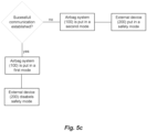
Figs. 5a-c are schematic views of methods according to different embodiments; and -
Fig. 6 is a schematic view of an airbag system and an external device according to an embodiment. - The protective system enclosed herein comprises an
airbag system 100 for protecting a body part in case of an abnormal movement of a user and at least oneexternal device 200. Theexternal device 200 may for example be a bicycle or a bicycle lock. - The
airbag system 100 is configured to be used to detect an accident, such as a fall or collision, for example when a user is riding a bicycle. Theairbag system 100 may thus be configured for the specific use of riding a bicycle. For the airbag system to protect the user during an accident, the user has to wear the airbag system and have it turned on, or activated when performing the specific activity. It would however be preferred to provide a system that determines if the airbag system is needed and in response to that alert the user and/or change the mode of the airbag system and/or change the mode of the external device. - Furthermore, having the airbag system set in an activate state when the user is not doing the intended activity, e.g. not cycling, results in an undesirable energy loss since the airbag system is in an active state using battery power to power a sensor(s) and to process the movement data gathered therefrom, although there is no risk for a fall or collision.
- It would thus be beneficial if the computational demanding determination, if a user is about to fall or collide when doing the indented activity, e.g., riding a bicycle, is deactivated when it's not needed so as to reduce the overall energy consumption of the system.
- The system herein aims at determining if the airbag system is needed, in particular if a user is actually performing the intended activity or not. This information may for example be used to change the mode of the
airbag system 100 and/or the mode of the external device. - The system herein aims at determining if the
airbag system 100 is needed or not. This is done by differentiating between situations where theairbag system 100 is within a predetermined distance from theexternal device 200 and when they are far away from each other. This information may for example be used to change the mode of theairbag system 100 and/or the mode of theexternal device 200. - Before turning to a detailed description of the disclosed embodiments, an exemplifying environment of the
airbag system 100 device will be described with reference toFig. 1 to 3 , and an exemplifying environment of theexternal device 200 will be briefly described with reference toFig 4 . -
Fig. 1 shows anairbag system 100 according to an embodiment in its non-inflated state. Theairbag system 100 comprises anapparel 10 having the shape of a collar which is worn around theneck 2 of auser 3. An idea of theairbag system 100 is to provide a wearable airbag system for protecting a body part in case of an abnormal movement of a user, such as a fall or a collision. The airbag system described herein may for example be used instead of an ordinary rigid helmet, e.g. when bicycling. The airbag system is comfortable to wear, does not affect the user's hair style when worn and does not obstruct vision or hearing when worn in its non- inflated state. - The
collar 10 is placed around the neck of the user and has for that purpose a sealable opening 12, normally at the front of the collar. Alternatively, the opening 12 may be arranged at the back of thecollar 10 or at the shoulder portion of thecollar 10. Furthermore, the opening 12 may be totally or partly divideable. - In one embodiment, the opening 12 is sealed using interlocking means (not shown) to connect the ends of the
collar 10 e.g. adjacently the user's 3 throat or neck region. The interlocking means facilitates easy dressing and undressing of thecollar 10 on theuser 3. Furthermore, the position of the different parts of the interlocking means determines if theairbag system 100 is turned on (i.e. having power) or turned off, and if its turned on in an active state or in an idle state. - In another embodiment the sealing may be arranged as a zipper, buttons, a Velcro fastening, magnets, hooks, hanks, buckles, safety pins, straps or the like. The
collar 10 may be made of any kind of flexible material, such as acetate silk, jeans, fleece, cotton, beaver nylon or any other suitable fabric. - When the airbag system is not worn by the user, the
collar 10 can be put in a resting position to allow the user to easier carry thecollar 10 for example by putting it in a bag. All electronics in the airbag system is turned off when the airbag system is put in the resting position. In the resting position the collar is connected such that the diameter of the collar is greatly reduce. This prevents the user from being able to have tocollar 10 arranged around the neck when the collar is in its resting position. - The
collar 10 comprises a foldedairbag 20 which is inflated to form a helmet for protecting the head of theuser 3 in case of an abnormal movement, e.g. during a cycling accident. - An inflated helmet is schematically shown in
Fig. 2 . Here, thecollar 10 is opened to release theairbag 20 previously enclosed therein. Theairbag 20 surrounds theneck 2 and thehead 4 of theuser 3 and provides an efficient protection for theuser 3. - The
airbag 20 is formed by a flexible material in order to be folded and stored within thecollar 10 prior to inflation. Theairbag 20 may e.g. comprise an inflatable inner bag surrounded by an outer bag. Inflation of the inner bag leads to expansion of the outer bag and the structure of the outer bag defines the shape of the airbag when the inner bag is inflated. Although not shown inFig. 1 and 2 , the airbag system may also be an one-bag construction. - The inner bag may be made of a fluid impermeable material, such as thermoplastic polyurethane film. Since fluid cannot easily leave a fluid impermeable bag, a person wearing an
airbag 20 according to the invention will be protected by saidairbag 20 for some time after expansion of theairbag 20, effectively protecting the head of the user for the entire time of the accident. The inner bag may be flexible and expandable such that it may expand the outer bag upon inflation to a high pressure. Hence, the inner bag may be inflated resulting in a relatively high internal pressure which may be maintained for some time. - An example of how the inner and outer bag may be configured is described in
WO2012044245 by the same applicant. - As shown in
Fig. 3 , theairbag system 100 further comprises at least onesensor 80 for detecting movement of thecollar 10, i.e. movement of theuser 3, and acontrol unit 50 configured to in response to the information gained by thesensor 80 determine if the movement corresponds to an accident situation. If an accident situation is determined, thecontrol unit 50 trigger inflation of theairbag 20 by means of aninflation device 60. Theairbag system 100 further comprises apower source 70, for example a rechargeable battery or a disposable battery, in order to provide electrical power to the parts of thesystem 100. The different parts will now be described more in detail. - The
inflation device 60 may be any suitable type of airbag inflation device, such as a hybrid generator using a combination of compromised gas and solid fuel, a pyrotechnic airbag inflator which uses hot gases formed by powder, a heated gas inflator or a an inflation device using solid fuel. In an embodiment, the inflation device is a cold gas inflator. - The
inflation device 60 is provided with agas guide 65, for directing the gas into the airbag. Theinflation device 60 is clamped, screwed, glued, sewed or the like onto the textile bag and thegas guide 65 is positioned inside the textile bag for directing the gas into the bag for inflating the airbag in a proper manner. Thegas guide 65 may be T-shaped for being able to lead the gas into the airbag in a suitable stable way. Alternatively thegas guide 65 may be Y- shaped, I-shaped, arrow-shaped, multiple-part shaped cylindrical shaped or the like. - The inflation of the
airbag 20 is controlled by thecontrol unit 50. Thecontrol unit 50 controls the inflation of the airbag in case of an abnormal movement and prevents the airbag system from releasing at an undesired occasion. Thecontrol unit 50 may be implemented using instructions that enable hardware functionality, for example, by using executable computer program instructions in a general-purpose or special-purpose processor that may be stored on a computer readable storage medium (disk, memory etc.) 52 to be executed by such a processor. Thecontrol unit 50 may be configured to read instructions from thememory 52 and to execute these instructions to control the operation of theairbag system 100. Thecontrol unit 50 may be implemented using any suitable, publically available processor or Programmable Logic Circuit (PLC). Thememory 52 may be implemented using any commonly known technology for computer-readable memories such as ROM, RAM, SRAM, DRAM, FLASH, DDR, SDRAM or some other memory technology. - The
control unit 50 may be adedicated control unit 50 or thecontrol unit 50 may also be configured to control other functions. - The at least one
sensor 80 collects data relating to the movement of thecollar 10. Thesensor 80 may be an accelerometer, a gyro, an air ultrasonic transducer, radar and/or a laser. In one embodiment at least one sensor is an accelerometer measuring acceleration in three dimensions and/or the sensor is a gyro detecting angular speed in three dimensions. Additionally, or alternatively, the at least onesensor 80 may be an ultrasonic transducer, or any device using electromagnetic waves, that measures the distance from the ground to thecollar 10. -
EP2313814 , filed by the same applicant, discloses a method for detecting a bicycle accident without falsely classifying any data samples from normal cycling activities as accident. The system classifies the detected movement into either a "normal class" relating to movement patterns representing riding a bicycle or doing related activities or into an "action class" relating to movement patterns representing a bicycle accident. - The movement data gathered from the at least one
sensor 80 is transmitted to thecontrol unit 50. Thecontrol unit 50 processes the data and analyses it in order to evaluate if the processed data corresponds to an accident situation.. If the data corresponds to pre-stored data indicating an accident situation, thecontrol unit 50 transmits a triggering signal to theinflation device 60 to trigger the inflation of theairbag 20. Theairbag 20 will consequently be inflated when theinflation device 60 receives the triggering signal. - The controller is coupled to the
memory 52, which saves the measured and processed data. The saved data can be used to review and analyse the activity history of the airbag system. This is particularly useful if the airbag system has been deflated and technicians want to verify that the airbag system was working properly. - The
airbag system 100 further comprises acommunication interface 90, which is adapted to allow theairbag system 100 to communicate with other devices through the use of different communication technologies. Such communication technologies may be wired or wireless. Examples of such wired technologies are Universal Serial Bus (USB) and Ethernet to name a few. Examples of such wireless technologies are IEEE 802.11, IEEE 802.15, ZigBee, WirelessHART, WIFI, Bluetooth®, W-CDMA/HSPA, GSM, UTRAN and LTE to name a few. It should be noted that other technologies exist and are taken to be an obvious equivalent for such wireless communication interfaces. - Preferably, the
communication interface 90 uses short-range wireless communication such as any of Bluetooth®, WLAN/WiFi, NFC (Near Field Communication), RF-ID (Radio Frequency Identification) or IrDA (Infrared Data Association). - If the
communication interface 90 uses Bluetooth, thecommunication interface 90 has the benefit that it also can measure the distance between theairbag system 100 and other devices. This distance can for example be used to determine if the airbag system is to be put in an active or idle state. - The
airbag system 100 may further comprise a user interface 95. The user interface 95 produces a signal detectable by the user, so as to alert theuser 3 with different information. The user interface 95 may be used to alert theuser 3 that his/hersexternal device 200 is nearby in order to remind the user to put theairbag system 100 in an active state and/or to alert that his/herexternal device 200 is far away and thus remind the user to turn off theairbag system 100. The user interface 95 may also be configured to indicate the status of theairbag system 100, i.e. the battery level, if the battery is in need for charging, if the inner elements of the helmet is intact or not, and if thesystem 100 is turned on. The user interface 95 may also indicate if thesystem 100 is turned on in an idle state or an active state. - The alert signal could be in the form of an audible signal such as siren, a haptic signal such as a vibration, a visual signal such as a strobe light or other sensory alarm that could be arranged on a user in the form of an
airbag system 100. - The user interface 95 may comprise one or a plurality of light emitting diodes (LED), which indicate information using light signal(s). Different colors of the light or flashing signals may for example indicate different information. The user interface 95 may also comprise a
speaker 112 sending out a sound signal, such as a buzz, or a device sending out a vibrating signal or a spoken phrase. - In an embodiment where the user interface 95 comprises a
speaker 112, thespeaker 112 may be used to send sound signals from anexternal device 200, transmitted using thecommunication interface 90. Thisexternal device 200 may be a differentexternal device 200 than the one previously mentioned. These sound signals may e.g. comprise navigational signals directing the user where to turn, possibly using a global positioning system (GPS) 260 of an external device 200 (seeFig. 6 ). - The
airbag system 100 has to be turned on, i.e. having power, in order to work properly. In one embodiment theairbag system 100 is turned on using an on/off-button arranged somewhere on thecollar 10. In yet one embodiment, theairbag system 100 is turned on automatically once thecollar 10 is placed around theneck 2 of theuser 3. - In some embodiments, the
airbag system 100 may either be turned on in an activate state or in an idle state. In the active state all parts of theairbag system 100 are active and the airbag is thus allowed to be inflated by a triggering signal. In the idle state theairbag systems 100 is powered up but other functions may be idle. In idle mode, thecontrol unit 50 may be active whereas theinflation device 60 and the sensor(s) 80 is inactivated (i.e. no triggering signal is detected and the airbag is not inflated). - In one embodiment, the idle state and the active state is turned on/off by the interlocking means arranged on the
collar 10. The interlocking means comprises a first fastening body and a second fastening body. One end of the first and second fastening body are each connected to thecollar 10. Thecollar 10 is thus easily attached to the neck of the user by attaching the first fastening body and the second fastening body to each other, and thecollar 10 is released from the neck of theuser 3 by detaching the first and second fastening bodies from each other. In a preferred embodiment, the first and second fastening body are a female and male connector. - The interlocking means is configured to be arranged in a first locking position or a second locking position when the first fastening body and the second fastening body are connected to each other. When the interlocking means is in a first locking position, the
system 100 is put into an idle state and when the interlocking means is in a second locking position, thesystem 100 is put into an active state. - As already mentioned, the
protective airbag system 100 further comprises anexternal device 200, which will now be briefly described with reference toFig. 4 . - In the embodiment shown in
Fig. 4 and in the following description, the external device is shown in the form of abicycle 200. However, the external device mentioned herein is not limited to these examples but may take any possible form as long thedevice 200 comprises means for communicating within theairbag system 100. If the indented use for theairbag system 100 is riding a bicycle, theexternal device 200 may for example be a bicycle lock or any other device suitable for attachment on or in conjunction of a bicycle. If the intended use of theairbag system 100 is horse riding, theexternal device 200 may be a device suitable to be arranged on the horse, for example a saddle or a bridle. - The bicycle may be of any type of bicycle having at least one wheel such as a bicycle with one wheel, i.e. a unicycle, an ordinary bicycle having two wheels, a tricycle having three wheels or a quadracycle having four wheels. The bicycle may for example be a utility bicycle, mountain bicycles racing bicycle, hybrid bicycle, BMX bike, a tandem or an electric bicycle.
- In the embodiment shown in
Fig. 5 , thebicycle 200 comprises two wheels, a frame, two pedals, a saddle and a front set having a handlebar grip. However, theexternal device 200 is not limited to any particular kind when it comes to physical design. - The
external device 200 may also be a separate device which is configured to be attached to the bicycle. - The
external device 200 further comprises means for communication. Theexternal device 200 may comprise acommunication interface 290 that communicates with thecommunication interface 90 arranged in thecollar 10. Preferably, thecommunication interface 290 uses short-range wireless data communication, such as short-range wireless data communication such as, for instance, Bluetooth®, WLAN/WiFi, NFC (Near Field Communication), RF-ID (Radio Frequency Identification) or IrDA (Infrared Data Association). - If the
communication interface 290 uses Bluetooth, thecommunication interface 290 has the benefit that it also can measure the distance betweenexternal device 200 and other devices such as theairbag system 100. This distance can for example be used to determine if a communication is successfully achieved. - In some embodiments, the
external device 200 further comprises acontroller 250. Thecontroller 250 may be responsible for general device operations of theexternal device 200, for example controlling the speed and/or the ON-OFF function of the external device. This is particularly true in the embodiments where theexternal device 200 is an electrically powered bicycle. - The
controller 250 may be implemented using any suitable, publically available processor or Programmable Logic Circuit (PLC). Thecontroller 250 may be in operative connection with a memory (not shown). The memory may be implemented using any commonly known technology for computer-readable memories such as ROM, RAM, SRAM, DRAM, FLASH, DDR, SDRAM or some other memory technology. - In some embodiments, the
external device 200 comprises auser interface 295. Theuser interface 295 produces a signal detectable by the user, so as to alert theuser 3 with different information. Theuser interface 295 may be used to alert theuser 3 that his/herairbag system 100 is turned off or in an idle ON-state and thus remind theuser 3 to turn on theairbag system 100. Theuser interface 295 may also be configured to indicate the status of theexternal device 200 such as the battery level. - Preferably, the
user interface 295 may comprise one or a plurality of light emitting diodes (LED), which indicate information using light signal(s). Different colors of the light may for example indicate different information. - The alert signal could also be in the form of an audible signal such as siren or a buzz or other sensory alarm that could be arranged on the
external device 200. - If the bicycle is an electric bicycle it may also comprises an integrated electric motor (not shown) which can be used for propulsion and a controller for controlling the applied speed. There are many possible types of electric motorized bicycles with several technologies available and these will thus not be described further.
- In another embodiment, as is schematically illustrated in
Fig. 6 , theexternal device 200 is amobile phone 210. The user interface 95 of theairbag system 100 comprises aspeaker 112, configured to transmit sound signals generated by themobile phone 210, and transmitted using thecommunication interface 90. These sound signals may e.g. be streamed audio data, comprising real-time navigational signals directing the user where to turn, possibly using a global positioning system (GPS) 260 of themobile phone 210. - The provision of a protective system comprising an
airbag system 100 and aexternal device 200 which differentiates between when theairbag system 100 and theexternal device 200 are within a predetermined distance or not solves or at least reduces the problem of having a person riding a bicycle without turning on theairbag system 100 and/or having a person walking around with theairbag system 100 in a powered state. This is done by the fact that theairbag system 100 and theexternal device 200 in the protective system interacts wirelessly with each other. If theairbag system 100 succeeds in establishing a short-range wireless data communication with theexternal device 200, one can assume that theuser 3 of theairbag system 100 is in the vicinity of theexternal device 200. The communication may be used to change the mode of theairbag system 100 and/or the mode of theexternal device 200 depending on the communication status. - In the embodiment where the
external device 200 is a bicycle or a bicycle lock the communication has several benefits, as will now be described. - The
airbag system 100 is intended to be worn when riding a bicycle and is configured to determine if an accident, such as a fall or collision, has occurred when riding the bicycle. In order to reduce the power consumption and the possible risk of theairbag system 100 inflating unintentionally, theairbag system 100 should only be turned on, or turned on in an active state, when theuser 3 is riding the bicycle or is in proximity of the bicycle (intending to ride the bike, or if he/she just got off the bike). If theairbag system 100 is turned on, or turned on in an active state, when theuser 3 is moving away from his/hers bicycle 200, it would be preferable if thesystem 100 would be turned off or turned into an idle ON-state. - Furthermore, if the
airbag system 100 is not turned on, or turned on in an idle state, while theuser 3 is in proximity of his/hers bicycle 200 it would be beneficial if thebicycle 200 was put in a safety mode where the speed of the bicycle is reduced or where its not possible to bike at all (due to power cut off in the case of an electric bicycle or by a locking device). - According to the invention, the
communication interface 90 of theairbag system 100 is configured to attempt to communicate with theexternal device 200 using wireless communication. Additionally, or alternatively, theexternal device 200 is configured to attempt to communicate with theairbag system 100. - This attempt is conducted at predetermined time intervals, for example every 30 seconds, every minute or every second minute. The attempt may also be more seldom, such as every fifth minute.
- In some embodiments the communication attempt is only conducted when it is detected that the
user 3 of theairbag system 100 is walking and/or not riding a bicycle. In some embodiments theairbag system 100 is configured to determine what activity state the user is in, e.g. if the user is walking or riding a bicycle, based on movement data gathered from at least one sensor, the sensor either being the same as the sensor colleting movement data for triggering of the inflation or an additional sensor. The communication attempt may then be conducted only when theairbag system 100 is in a walking activity state, or when the user is not in a bicycling activity state. - In one embodiment the communication between the
airbag system 100 and theexternal device 200 is considered to be successful if a communication is established between theairbag system 100 and theexternal device 200. In another embodiment the communication between theairbag system 100 and theexternal device 200 is successful if a communication is established between theairbag system 100 and theexternal device 200 and if theairbag system 100 and theexternal device 200 are within a predetermined distance from each other. The predetermined distance may be measured by thecommunication interface 90 of the airbag system and/or by the communication means 290 of theexternal device 200. - The communication between the
airbag system 100 and theexternal device 200 will now be described further with exemplified embodiments with reference toFigs.5a-b . - As seen in the embodiment of
Fig. 5a , if the communication between theairbag system 100 and theexternal device 200 is successful, thecontrol unit 50 of theairbag system 100 is configured to put theairbag system 100 in a first mode. Depending on configuration the first mode may pertain to different functions. - In the first mode the
control unit 50 may be configured to alert theuser 3 that he/she should manually turn on, or turn on in an activate state, theairbag system 100 since he/she is in close proximity of thebicycle 200. If theairbag system 100 already is turned on, or turned on in an activate state, thecontrol device 50 may be configured to not alert the user. The alert to theuser 3 may be generated by the user interface 95 which produces a signal detectable by the user as described with reference toFig. 3 . - Additionally, or alternatively, the
control unit 50 may be configured, in the first mode, to automatically put theairbag system 100 in an active state if theairbag system 100 has an idle ON-state and an active ON-state. In this way theairbag system 100 is always turned on and ready to protect theuser 3 in case of a bicycle accident when thebicycle 200 is in proximity to theuser 3. - If instead the communication between the
airbag system 100 and theexternal device 200 is not successful, i.e. either the communication establishment fails or the communication is established but theairbag system 100 and theexternal device 200 is not within the predetermined distance from each other, thecontrol unit 50 of theairbag system 100 is configured to put theairbag system 100 in a second mode. Depending on configuration the second mode may pertain to different functions. - In the second mode the
control unit 50 may be configured to alert theuser 3 that he/she should manually turn off, or turn the airbag system in an idle state, since he/she is not in close proximity of thebicycle 200. If theairbag system 100 already is turned on in an idle state, thecontrol device 50 may be configured to not alert theuser 3. - Additionally, or alternatively, the
control unit 50 may be configured, in the second mode, to automatically turn off theairbag system 100 or put theairbag system 100 in an idle state if theairbag system 100 has an idle ON-state and active ON-state. In this way theairbag system 100 is turned off, or turned into an idle ON-state, once theuser 3 is not in proximity of thebicycle 200. This reduces battery consumption of theairbag system 100 and eliminates the possible risk of theairbag 20 being inflated unintentional. - In the embodiment shown in
Fig. 5b , the state of theexternal device 200 ischanged depending on the communication between theairbag system 100 and theexternal device 200. As seen in the embodiment ofFig. 5b , if the communication between theairbag system 100 and theexternal device 200 is successful the controller of theexternal device 200 is configured to disable theexternal device 200 from a safety mode, if activated. - If instead the communication between the
airbag system 100 and theexternal device 200 is not successful, i.e. fails, the controller of theexternal device 200 is configured to put theexternal device 200 in a safety mode of theexternal device 200. - Depending on configuration the safety mode may pertain to different functions. In the safety mode the
controller 250 of the external device may be configured to alert theuser 3 to put on theairbag system 100 in an idle mode. This may for example be done by a light indicator visibly arranged on theexternal device 200. - Additionally, or alternatively, the
controller 250 of theexternal device 200 may be configured, in the safety mode, to prevent theuser 3 from using theexternal device 200. This may for example be prevented by locking the bicycle by a locking device (not shown) which is locked in a safety mode and unlocked when the safety mode is disabled. Such a locking device may be a smart lock which is able to communicate with theexternal device 200, so as to open the lock when the safety mode is disabled. - In the embodiment where the
external device 200 is a bicycle lock, the locking device is able to communicate with theairbag system 100 so that the safety mode of theexternal device 200 pertains to locking the bicycle lock. Disabling the safety mode thus means opening the bicycle lock. - In the embodiment where the
external device 200 is an electric bicycle, the user could also be prevented from using thebicycle 200 by having a safety mode configured to lock theelectric bicycle 200 so as to prevent theuser 3 from using it by power cutoff. Alternatively, the safety mode is configured to reduce the maximum allowed speed of theelectrical bicycle 200. In this way, if theuser 3 is not wearing theairbag system 100, or the system is not turned on in an active state, the bicycle cannot be used or can only be used at a slow speed. - The two embodiments disclosed in
Fig. 5a-b can be combined. One such combination is seen inFig. 5c , showing that if the communication is successful theairbag system 100 is put in a first mode and theexternal device 200 disables the safety mode, if present. If the communication fails, theairbag system 100 is put in a second mode and theexternal device 200 is put in a safety mode. - It should be understood that different combinations of the different configurations could be made and that the configurations could be made simultaneously with each other or in a prescribed order, e.g. first put the
external device 200 in a safety mode and then put theairbag system 100 in a second mode.
Claims (12)
- Protective system, comprising:an airbag system (100) in the form of an inflatable helmet for protecting a body part of a user (3) in case of an accident, comprising a control unit (50) and a communication interface (90); andan external device (200) comprising communication means (290),wherein the communication interface (90) of the airbag system (100) is configured to communicate with said external device (200) using wireless communication,wherein the communication interface (90) of the airbag system (100) is configured to attempt to communicate with said external device (200),characterized in thatif the communication between the airbag system (100) and the external device (200) is not successful, the control unit (50) of the airbag system (100) is configured to put the airbag system (100) in an idle state and/or to alert the user (3) to manually change to an idle state, andif the communication between the airbag system (100) and the external device (200) is successful, the control unit (50) of the airbag system (100) is configured to put the airbag system (100) in an active state and/or to alert the user (3) to manually change to an active state.
- The protective system according to claim 1, wherein the wireless communication is short-range wireless communication, optionally wherein the short-range wireless communication may pertain to any of Bluetooth, WLAN, WiFi, NFC, RF-ID or IrDA.
- The protective system according to claim 1 or 2, wherein the communication between the airbag system (100) and the external device (200) is successful when a communication is established between the airbag system (100) and the external device (200).
- The protective system according to any of claims 1-3, wherein the communication between the airbag system (100) and the external device (200) is successful when a communication is established between the airbag system (100) and the external device (200), and the external device (200) and the airbag system (100) are within a predetermined distance from each other.
- The protective system according to any of claims 1-3, wherein the communication between the airbag system (100) and the external device (200) is unsuccessful when communication fails to establish between the airbag system (100) and the external device (200).
- The protective system according to claim 3, wherein the communication between the airbag system (100) and the external device (200) is unsuccessful when a communication is established between the airbag system (100) and the external device (200), but the external device (200) and the airbag system (100) are not within a predetermined distance from each other.
- The protective system according to any of claims 1 to 6, wherein if the communication between the airbag system (100) and the external device (200) is not successful, a controller (250) of the external device (200) is configured to control the external device (200) into a safety mode.
- The protective system according to any of claims 1 to 7, wherein if the communication between the airbag system (100) and the external device (200) is successful a controller (250) of the external device (200) is configured to disable a safety mode of the external device (200).
- The protective system according to claim 1 or 8, wherein in the safety mode the controller (250) of the external device (200) is configured to lock the external device (200) so as to prevent the user (3) from using it.
- The protective system according to any of claims 1 to 9, wherein the external device (200) is an electric bicycle and wherein in the safety mode the controller (250) of the electric bicycle (200) is configured to lock the electric bicycle (200) so as to prevent the user (3) from using it or to reduce the allowed speed of the electrical bicycle (200).
- The protective system according to any of claims 1 to 10, wherein the external device (200) is a bicycle, a bicycle lock, or a mobile phone (210).
- The protective system according to claim 11, said external device (200) being a mobile phone (210), wherein the airbag system (100) comprises a speaker (112), and wherein the mobile phone (210) is configured to stream audio data to said speaker (112), optionally wherein the audio data is real-time navigation audio.
Applications Claiming Priority (2)
| Application Number | Priority Date | Filing Date | Title |
|---|---|---|---|
| SE1750847A SE543798C2 (en) | 2017-06-29 | 2017-06-29 | Protective system comprising an airbag system in the form of an inflatable helmet, a control unit and a communication interface |
| PCT/SE2018/050703 WO2019004919A1 (en) | 2017-06-29 | 2018-06-28 | Protective system comprising an airbag system with an inflatable helmet communicating with an external device |
Publications (4)
| Publication Number | Publication Date |
|---|---|
| EP3644774A1 EP3644774A1 (en) | 2020-05-06 |
| EP3644774A4 EP3644774A4 (en) | 2021-06-09 |
| EP3644774B1 true EP3644774B1 (en) | 2024-10-23 |
| EP3644774B8 EP3644774B8 (en) | 2024-11-27 |
Family
ID=64742900
Family Applications (1)
| Application Number | Title | Priority Date | Filing Date |
|---|---|---|---|
| EP18825360.3A Active EP3644774B8 (en) | 2017-06-29 | 2018-06-28 | Protective system comprising an airbag system with an inflatable helmet communicating with an external device |
Country Status (12)
| Country | Link |
|---|---|
| US (1) | US11518328B2 (en) |
| EP (1) | EP3644774B8 (en) |
| JP (1) | JP2020525665A (en) |
| KR (1) | KR20200043313A (en) |
| CN (1) | CN110809413B (en) |
| AU (1) | AU2018291549A1 (en) |
| CA (1) | CA3064991A1 (en) |
| DK (1) | DK3644774T3 (en) |
| ES (1) | ES2997759T3 (en) |
| FI (1) | FI3644774T3 (en) |
| SE (1) | SE543798C2 (en) |
| WO (1) | WO2019004919A1 (en) |
Families Citing this family (13)
| Publication number | Priority date | Publication date | Assignee | Title |
|---|---|---|---|---|
| SE1750845A1 (en) * | 2017-06-29 | 2018-12-30 | Hoevding Sverige Ab | Imroved airbag system |
| US11464270B2 (en) * | 2018-12-03 | 2022-10-11 | Brian Michael Coyle | Rotation damping helmet |
| US20230248104A1 (en) * | 2018-12-03 | 2023-08-10 | Brian Michael Coyle | Helmet rotation damping with negative torque |
| US11613220B2 (en) | 2018-12-17 | 2023-03-28 | Lear Corporation | Electrical assembly |
| SE543224C2 (en) * | 2019-03-01 | 2020-10-27 | Hoevding Sverige Ab | Accident prevention system comprising a wearable airbag system and methods therefore |
| ES1227169Y (en) | 2019-03-12 | 2019-06-18 | Solanellas Marc Millet | PROTECTION DEVICE FOR PROTECTING THE CRANIAL AND YEAR AREA OF A USER AGAINST AN IMMINENT IMPACT |
| US20210107419A1 (en) * | 2019-10-09 | 2021-04-15 | Lear Corporation | Electrical assembly |
| KR102362448B1 (en) * | 2020-01-06 | 2022-02-15 | 주식회사 비디오 | Apparatus for requesting rescue using the portable air cleaner |
| KR102417173B1 (en) * | 2020-09-23 | 2022-07-05 | 주식회사 유라코퍼레이션 | Occupant protection system for electric kickboard and control method thereof |
| JP2023061790A (en) * | 2021-10-20 | 2023-05-02 | 株式会社プロップ | Airbag device for human body |
| KR102594929B1 (en) * | 2021-11-24 | 2023-10-27 | 주식회사 에이치에이치에스 | Smart helmet with state detection function and shock-absorbing structure |
| FR3135193A1 (en) * | 2022-05-04 | 2023-11-10 | Freejumpsystem | Rider protection system including an airbag vest connected to a horse fall sensor |
| KR20250062158A (en) * | 2023-10-30 | 2025-05-08 | 현대자동차주식회사 | Safety device storage kit for personal mobility device |
Family Cites Families (17)
| Publication number | Priority date | Publication date | Assignee | Title |
|---|---|---|---|---|
| FR2735661B1 (en) * | 1995-06-21 | 1997-08-01 | Bultel Alain | SAFETY METHOD AND DEVICE FOR MOTORCYCLISTS |
| JP2002264874A (en) | 2001-03-12 | 2002-09-18 | Toshiba Corp | Communication device for motorcycle, helmet and anti-theft device using this communication device |
| US7150048B2 (en) * | 2002-12-18 | 2006-12-19 | Buckman Robert F | Method and apparatus for body impact protection |
| ES2270669B1 (en) * | 2004-10-05 | 2008-02-16 | Apc Systems Bcn, S.L. | AIRBAG MODULE OF CERVICO-DORSAL PROTECTION. |
| RU2008139877A (en) | 2006-03-08 | 2010-04-20 | Томтом Интернэшнл Б.В. (Nl) | PORTABLE NAVIGATION DEVICE |
| DE102006037731A1 (en) * | 2006-08-11 | 2008-02-14 | Röder, Roland | Monitoring system e.g. for motor vehicle, has central PC module which receives information from several sensors arranged on vehicle and which is connected to storage device |
| ES1067521Y (en) | 2008-03-11 | 2009-04-16 | Urena Damian Torres | AIRBAG-COLLARIN FOR INTEGRAL OR PARTY HELMET |
| EP2313814B1 (en) | 2008-07-18 | 2016-03-30 | Hövding Sverige AB | A method, device, and computer program product for event detection while preventing misclassification |
| JP5421166B2 (en) * | 2010-03-24 | 2014-02-19 | 本田技研工業株式会社 | Airbag jacket actuation system |
| RU110058U1 (en) | 2010-04-30 | 2011-11-10 | Общество с ограниченной ответственностью "Коммуникационное агентство "Диксон" | BICYCLE PARKING FOR RENT BICYCLES |
| CN103153102B (en) | 2010-09-29 | 2015-04-08 | 霍丁斯瑞典有限公司 | Airbag suitable for head protection |
| ITTV20120124A1 (en) * | 2012-06-26 | 2013-12-27 | Alpinestars Res Srl | INFLATABLE PROTECTION DEVICE MOUNTED ON THE LINING AND PROTECTIVE CLOTHING ASSEMBLY |
| KR200474020Y1 (en) * | 2013-06-19 | 2014-08-18 | (주)넥스트로닉스 | Helmet safety apparatus |
| DE102013217851B4 (en) * | 2013-09-06 | 2025-02-20 | Robert Bosch Gmbh | Safety system for a motorcycle and triggering method of a safety system |
| US20160086489A1 (en) | 2014-09-23 | 2016-03-24 | Ford Global Technologies, Llc | E-bike to infrastructure or vehicle communication |
| CN104853401B (en) | 2015-04-20 | 2019-01-04 | 小米科技有限责任公司 | The method and apparatus for controlling access |
| CN106137210B (en) * | 2016-07-14 | 2019-04-23 | 北京机械设备研究所 | A kind of tumble guard system and means of defence |
-
2017
- 2017-06-29 SE SE1750847A patent/SE543798C2/en unknown
-
2018
- 2018-06-28 FI FIEP18825360.3T patent/FI3644774T3/en active
- 2018-06-28 WO PCT/SE2018/050703 patent/WO2019004919A1/en not_active Ceased
- 2018-06-28 AU AU2018291549A patent/AU2018291549A1/en not_active Abandoned
- 2018-06-28 KR KR1020197038228A patent/KR20200043313A/en not_active Ceased
- 2018-06-28 EP EP18825360.3A patent/EP3644774B8/en active Active
- 2018-06-28 CA CA3064991A patent/CA3064991A1/en active Pending
- 2018-06-28 JP JP2019572722A patent/JP2020525665A/en active Pending
- 2018-06-28 DK DK18825360.3T patent/DK3644774T3/en active
- 2018-06-28 ES ES18825360T patent/ES2997759T3/en active Active
- 2018-06-28 CN CN201880043486.3A patent/CN110809413B/en active Active
- 2018-06-28 US US16/626,929 patent/US11518328B2/en active Active
Also Published As
| Publication number | Publication date |
|---|---|
| SE1750847A1 (en) | 2018-12-30 |
| AU2018291549A1 (en) | 2019-12-19 |
| EP3644774A1 (en) | 2020-05-06 |
| US20200139913A1 (en) | 2020-05-07 |
| CN110809413B (en) | 2022-03-22 |
| FI3644774T3 (en) | 2025-01-17 |
| KR20200043313A (en) | 2020-04-27 |
| US11518328B2 (en) | 2022-12-06 |
| JP2020525665A (en) | 2020-08-27 |
| CA3064991A1 (en) | 2019-01-03 |
| EP3644774B8 (en) | 2024-11-27 |
| DK3644774T3 (en) | 2024-12-16 |
| RU2019140372A (en) | 2021-07-29 |
| RU2019140372A3 (en) | 2021-11-25 |
| ES2997759T3 (en) | 2025-02-18 |
| SE543798C2 (en) | 2021-07-27 |
| WO2019004919A1 (en) | 2019-01-03 |
| CN110809413A (en) | 2020-02-18 |
| EP3644774A4 (en) | 2021-06-09 |
Similar Documents
| Publication | Publication Date | Title |
|---|---|---|
| EP3644774B1 (en) | Protective system comprising an airbag system with an inflatable helmet communicating with an external device | |
| US11510450B2 (en) | Airbag system | |
| EP3171723B1 (en) | "protective garment provided with an inflatable protective device and associated inflating method" | |
| KR101302175B1 (en) | System and method for protecting a bodypart | |
| CN113924019A (en) | Protection device for protecting the skull and cervical region of a user against an impending impact | |
| WO2019022675A1 (en) | Wearable apparatus, method and controller thereof | |
| KR20180036870A (en) | Safe driving device of a bicycle | |
| CN211794420U (en) | Human body protection safety airbag clothes | |
| RU2772999C2 (en) | Advanced air bag system | |
| EP3911193B1 (en) | Activation system for wearable airbag | |
| WO2019004920A1 (en) | Imroved airbag system |
Legal Events
| Date | Code | Title | Description |
|---|---|---|---|
| STAA | Information on the status of an ep patent application or granted ep patent |
Free format text: STATUS: THE INTERNATIONAL PUBLICATION HAS BEEN MADE |
|
| PUAI | Public reference made under article 153(3) epc to a published international application that has entered the european phase |
Free format text: ORIGINAL CODE: 0009012 |
|
| STAA | Information on the status of an ep patent application or granted ep patent |
Free format text: STATUS: REQUEST FOR EXAMINATION WAS MADE |
|
| 17P | Request for examination filed |
Effective date: 20200123 |
|
| AK | Designated contracting states |
Kind code of ref document: A1 Designated state(s): AL AT BE BG CH CY CZ DE DK EE ES FI FR GB GR HR HU IE IS IT LI LT LU LV MC MK MT NL NO PL PT RO RS SE SI SK SM TR |
|
| AX | Request for extension of the european patent |
Extension state: BA ME |
|
| DAV | Request for validation of the european patent (deleted) | ||
| DAX | Request for extension of the european patent (deleted) | ||
| A4 | Supplementary search report drawn up and despatched |
Effective date: 20210510 |
|
| RIC1 | Information provided on ipc code assigned before grant |
Ipc: A41D 13/018 20060101AFI20210503BHEP Ipc: A42B 3/00 20060101ALI20210503BHEP Ipc: A42B 3/04 20060101ALI20210503BHEP |
|
| P01 | Opt-out of the competence of the unified patent court (upc) registered |
Effective date: 20230528 |
|
| GRAP | Despatch of communication of intention to grant a patent |
Free format text: ORIGINAL CODE: EPIDOSNIGR1 |
|
| STAA | Information on the status of an ep patent application or granted ep patent |
Free format text: STATUS: GRANT OF PATENT IS INTENDED |
|
| INTG | Intention to grant announced |
Effective date: 20231128 |
|
| GRAS | Grant fee paid |
Free format text: ORIGINAL CODE: EPIDOSNIGR3 |
|
| 19U | Interruption of proceedings before grant |
Effective date: 20231221 |
|
| 19W | Proceedings resumed before grant after interruption of proceedings |
Effective date: 20240801 |
|
| RAP3 | Party data changed (applicant data changed or rights of an application transferred) |
Owner name: ISI AUTOMOTIVE SWEDEN AB |
|
| GRAA | (expected) grant |
Free format text: ORIGINAL CODE: 0009210 |
|
| STAA | Information on the status of an ep patent application or granted ep patent |
Free format text: STATUS: THE PATENT HAS BEEN GRANTED |
|
| REG | Reference to a national code |
Ref country code: DE Ref legal event code: R081 Ref document number: 602018075799 Country of ref document: DE Owner name: ISI AUTOMOTIVE HOLDING GMBH, AT Free format text: FORMER OWNER: ISI AUTOMOTIVE SWEDEN AB, STOCKHOLM, SE Ref country code: DE Ref legal event code: R081 Ref document number: 602018075799 Country of ref document: DE Owner name: ISI WEARABLE SAFETY GMBH, AT Free format text: FORMER OWNER: ISI AUTOMOTIVE SWEDEN AB, STOCKHOLM, SE |
|
| AK | Designated contracting states |
Kind code of ref document: B1 Designated state(s): AL AT BE BG CH CY CZ DE DK EE ES FI FR GB GR HR HU IE IS IT LI LT LU LV MC MK MT NL NO PL PT RO RS SE SI SK SM TR |
|
| REG | Reference to a national code |
Ref country code: GB Ref legal event code: FG4D |
|
| REG | Reference to a national code |
Ref country code: CH Ref legal event code: PK Free format text: BERICHTIGUNG B8 Ref country code: CH Ref legal event code: EP |
|
| RAP2 | Party data changed (patent owner data changed or rights of a patent transferred) |
Owner name: ISI AUTOMOTIVE HOLDING GMBH |
|
| REG | Reference to a national code |
Ref country code: DE Ref legal event code: R096 Ref document number: 602018075799 Country of ref document: DE |
|
| REG | Reference to a national code |
Ref country code: IE Ref legal event code: FG4D |
|
| REG | Reference to a national code |
Ref country code: DK Ref legal event code: T3 Effective date: 20241212 |
|
| REG | Reference to a national code |
Ref country code: FI Ref legal event code: FGE |
|
| REG | Reference to a national code |
Ref country code: NL Ref legal event code: FP |
|
| REG | Reference to a national code |
Ref country code: SE Ref legal event code: TRGR |
|
| REG | Reference to a national code |
Ref country code: ES Ref legal event code: FG2A Ref document number: 2997759 Country of ref document: ES Kind code of ref document: T3 Effective date: 20250218 |
|
| REG | Reference to a national code |
Ref country code: LT Ref legal event code: MG9D |
|
| PG25 | Lapsed in a contracting state [announced via postgrant information from national office to epo] |
Ref country code: IS Free format text: LAPSE BECAUSE OF FAILURE TO SUBMIT A TRANSLATION OF THE DESCRIPTION OR TO PAY THE FEE WITHIN THE PRESCRIBED TIME-LIMIT Effective date: 20250223 Ref country code: PT Free format text: LAPSE BECAUSE OF FAILURE TO SUBMIT A TRANSLATION OF THE DESCRIPTION OR TO PAY THE FEE WITHIN THE PRESCRIBED TIME-LIMIT Effective date: 20250224 Ref country code: HR Free format text: LAPSE BECAUSE OF FAILURE TO SUBMIT A TRANSLATION OF THE DESCRIPTION OR TO PAY THE FEE WITHIN THE PRESCRIBED TIME-LIMIT Effective date: 20241023 |
|
| PG25 | Lapsed in a contracting state [announced via postgrant information from national office to epo] |
Ref country code: BG Free format text: LAPSE BECAUSE OF FAILURE TO SUBMIT A TRANSLATION OF THE DESCRIPTION OR TO PAY THE FEE WITHIN THE PRESCRIBED TIME-LIMIT Effective date: 20241023 |
|
| PG25 | Lapsed in a contracting state [announced via postgrant information from national office to epo] |
Ref country code: LV Free format text: LAPSE BECAUSE OF FAILURE TO SUBMIT A TRANSLATION OF THE DESCRIPTION OR TO PAY THE FEE WITHIN THE PRESCRIBED TIME-LIMIT Effective date: 20241023 Ref country code: GR Free format text: LAPSE BECAUSE OF FAILURE TO SUBMIT A TRANSLATION OF THE DESCRIPTION OR TO PAY THE FEE WITHIN THE PRESCRIBED TIME-LIMIT Effective date: 20250124 |
|
| PG25 | Lapsed in a contracting state [announced via postgrant information from national office to epo] |
Ref country code: PL Free format text: LAPSE BECAUSE OF FAILURE TO SUBMIT A TRANSLATION OF THE DESCRIPTION OR TO PAY THE FEE WITHIN THE PRESCRIBED TIME-LIMIT Effective date: 20241023 |
|
| PG25 | Lapsed in a contracting state [announced via postgrant information from national office to epo] |
Ref country code: RS Free format text: LAPSE BECAUSE OF FAILURE TO SUBMIT A TRANSLATION OF THE DESCRIPTION OR TO PAY THE FEE WITHIN THE PRESCRIBED TIME-LIMIT Effective date: 20250123 |
|
| PG25 | Lapsed in a contracting state [announced via postgrant information from national office to epo] |
Ref country code: SM Free format text: LAPSE BECAUSE OF FAILURE TO SUBMIT A TRANSLATION OF THE DESCRIPTION OR TO PAY THE FEE WITHIN THE PRESCRIBED TIME-LIMIT Effective date: 20241023 |
|
| PGFP | Annual fee paid to national office [announced via postgrant information from national office to epo] |
Ref country code: DE Payment date: 20250417 Year of fee payment: 8 |
|
| PGFP | Annual fee paid to national office [announced via postgrant information from national office to epo] |
Ref country code: GB Payment date: 20250620 Year of fee payment: 8 |
|
| PGFP | Annual fee paid to national office [announced via postgrant information from national office to epo] |
Ref country code: FR Payment date: 20250626 Year of fee payment: 8 |
|
| PG25 | Lapsed in a contracting state [announced via postgrant information from national office to epo] |
Ref country code: RO Free format text: LAPSE BECAUSE OF FAILURE TO SUBMIT A TRANSLATION OF THE DESCRIPTION OR TO PAY THE FEE WITHIN THE PRESCRIBED TIME-LIMIT Effective date: 20241023 |
|
| REG | Reference to a national code |
Ref country code: DE Ref legal event code: R097 Ref document number: 602018075799 Country of ref document: DE |
|
| PG25 | Lapsed in a contracting state [announced via postgrant information from national office to epo] |
Ref country code: SK Free format text: LAPSE BECAUSE OF FAILURE TO SUBMIT A TRANSLATION OF THE DESCRIPTION OR TO PAY THE FEE WITHIN THE PRESCRIBED TIME-LIMIT Effective date: 20241023 |
|
| PG25 | Lapsed in a contracting state [announced via postgrant information from national office to epo] |
Ref country code: CZ Free format text: LAPSE BECAUSE OF FAILURE TO SUBMIT A TRANSLATION OF THE DESCRIPTION OR TO PAY THE FEE WITHIN THE PRESCRIBED TIME-LIMIT Effective date: 20241023 |
|
| PGFP | Annual fee paid to national office [announced via postgrant information from national office to epo] |
Ref country code: SE Payment date: 20250618 Year of fee payment: 8 |
|
| PLBE | No opposition filed within time limit |
Free format text: ORIGINAL CODE: 0009261 |
|
| STAA | Information on the status of an ep patent application or granted ep patent |
Free format text: STATUS: NO OPPOSITION FILED WITHIN TIME LIMIT |
|
| RAP2 | Party data changed (patent owner data changed or rights of a patent transferred) |
Owner name: ISI WEARABLE SAFETY GMBH |
|
| REG | Reference to a national code |
Ref country code: DE Ref legal event code: R081 Ref document number: 602018075799 Country of ref document: DE Owner name: ISI WEARABLE SAFETY GMBH, AT Free format text: FORMER OWNER: ISI AUTOMOTIVE HOLDING GMBH, WIEN, AT |
|
| 26N | No opposition filed |
Effective date: 20250724 |
|
| REG | Reference to a national code |
Ref country code: GB Ref legal event code: 732E Free format text: REGISTERED BETWEEN 20250911 AND 20250917 |
|
| PG25 | Lapsed in a contracting state [announced via postgrant information from national office to epo] |
Ref country code: FI Free format text: LAPSE BECAUSE OF NON-PAYMENT OF DUE FEES Effective date: 20250628 |
|
| REG | Reference to a national code |
Ref country code: CH Ref legal event code: H13 Free format text: ST27 STATUS EVENT CODE: U-0-0-H10-H13 (AS PROVIDED BY THE NATIONAL OFFICE) Effective date: 20260127 |
|
| PG25 | Lapsed in a contracting state [announced via postgrant information from national office to epo] |
Ref country code: MC Free format text: LAPSE BECAUSE OF FAILURE TO SUBMIT A TRANSLATION OF THE DESCRIPTION OR TO PAY THE FEE WITHIN THE PRESCRIBED TIME-LIMIT Effective date: 20241023 |
|
| REG | Reference to a national code |
Ref country code: DK Ref legal event code: EBP Effective date: 20250630 |
|
| REG | Reference to a national code |
Ref country code: NL Ref legal event code: MM Effective date: 20250701 |
|
| PG25 | Lapsed in a contracting state [announced via postgrant information from national office to epo] |
Ref country code: LU Free format text: LAPSE BECAUSE OF NON-PAYMENT OF DUE FEES Effective date: 20250628 |
|
| REG | Reference to a national code |
Ref country code: BE Ref legal event code: MM Effective date: 20250630 |
|
| PG25 | Lapsed in a contracting state [announced via postgrant information from national office to epo] |
Ref country code: NL Free format text: LAPSE BECAUSE OF NON-PAYMENT OF DUE FEES Effective date: 20250701 |
|
| PG25 | Lapsed in a contracting state [announced via postgrant information from national office to epo] |
Ref country code: NO Free format text: LAPSE BECAUSE OF NON-PAYMENT OF DUE FEES Effective date: 20250630 Ref country code: IE Free format text: LAPSE BECAUSE OF NON-PAYMENT OF DUE FEES Effective date: 20250628 |
|
| PG25 | Lapsed in a contracting state [announced via postgrant information from national office to epo] |
Ref country code: IT Free format text: LAPSE BECAUSE OF NON-PAYMENT OF DUE FEES Effective date: 20250628 Ref country code: BE Free format text: LAPSE BECAUSE OF NON-PAYMENT OF DUE FEES Effective date: 20250630 |
|
| PG25 | Lapsed in a contracting state [announced via postgrant information from national office to epo] |
Ref country code: CH Free format text: LAPSE BECAUSE OF NON-PAYMENT OF DUE FEES Effective date: 20250630 |