EP3644704B1 - Manifold modules. system and agricultural implement comprising such manifold modules - Google Patents
Manifold modules. system and agricultural implement comprising such manifold modules Download PDFInfo
- Publication number
- EP3644704B1 EP3644704B1 EP18749889.4A EP18749889A EP3644704B1 EP 3644704 B1 EP3644704 B1 EP 3644704B1 EP 18749889 A EP18749889 A EP 18749889A EP 3644704 B1 EP3644704 B1 EP 3644704B1
- Authority
- EP
- European Patent Office
- Prior art keywords
- channel
- control
- module
- channels
- bypass
- Prior art date
- Legal status (The legal status is an assumption and is not a legal conclusion. Google has not performed a legal analysis and makes no representation as to the accuracy of the status listed.)
- Active
Links
Images





Classifications
-
- A—HUMAN NECESSITIES
- A01—AGRICULTURE; FORESTRY; ANIMAL HUSBANDRY; HUNTING; TRAPPING; FISHING
- A01B—SOIL WORKING IN AGRICULTURE OR FORESTRY; PARTS, DETAILS, OR ACCESSORIES OF AGRICULTURAL MACHINES OR IMPLEMENTS, IN GENERAL
- A01B63/00—Lifting or adjusting devices or arrangements for agricultural machines or implements
- A01B63/02—Lifting or adjusting devices or arrangements for agricultural machines or implements for implements mounted on tractors
- A01B63/10—Lifting or adjusting devices or arrangements for agricultural machines or implements for implements mounted on tractors operated by hydraulic or pneumatic means
-
- F—MECHANICAL ENGINEERING; LIGHTING; HEATING; WEAPONS; BLASTING
- F15—FLUID-PRESSURE ACTUATORS; HYDRAULICS OR PNEUMATICS IN GENERAL
- F15B—SYSTEMS ACTING BY MEANS OF FLUIDS IN GENERAL; FLUID-PRESSURE ACTUATORS, e.g. SERVOMOTORS; DETAILS OF FLUID-PRESSURE SYSTEMS, NOT OTHERWISE PROVIDED FOR
- F15B13/00—Details of servomotor systems ; Valves for servomotor systems
- F15B13/02—Fluid distribution or supply devices characterised by their adaptation to the control of servomotors
- F15B13/06—Fluid distribution or supply devices characterised by their adaptation to the control of servomotors for use with two or more servomotors
- F15B13/08—Assemblies of units, each for the control of a single servomotor only
- F15B13/0803—Modular units
- F15B13/0878—Assembly of modular units
- F15B13/0882—Assembly of modular units using identical modular elements
-
- A—HUMAN NECESSITIES
- A01—AGRICULTURE; FORESTRY; ANIMAL HUSBANDRY; HUNTING; TRAPPING; FISHING
- A01B—SOIL WORKING IN AGRICULTURE OR FORESTRY; PARTS, DETAILS, OR ACCESSORIES OF AGRICULTURAL MACHINES OR IMPLEMENTS, IN GENERAL
- A01B63/00—Lifting or adjusting devices or arrangements for agricultural machines or implements
- A01B63/02—Lifting or adjusting devices or arrangements for agricultural machines or implements for implements mounted on tractors
- A01B63/10—Lifting or adjusting devices or arrangements for agricultural machines or implements for implements mounted on tractors operated by hydraulic or pneumatic means
- A01B63/111—Lifting or adjusting devices or arrangements for agricultural machines or implements for implements mounted on tractors operated by hydraulic or pneumatic means regulating working depth of implements
-
- A—HUMAN NECESSITIES
- A01—AGRICULTURE; FORESTRY; ANIMAL HUSBANDRY; HUNTING; TRAPPING; FISHING
- A01B—SOIL WORKING IN AGRICULTURE OR FORESTRY; PARTS, DETAILS, OR ACCESSORIES OF AGRICULTURAL MACHINES OR IMPLEMENTS, IN GENERAL
- A01B63/00—Lifting or adjusting devices or arrangements for agricultural machines or implements
- A01B63/14—Lifting or adjusting devices or arrangements for agricultural machines or implements for implements drawn by animals or tractors
- A01B63/24—Tools or tool-holders adjustable relatively to the frame
- A01B63/32—Tools or tool-holders adjustable relatively to the frame operated by hydraulic or pneumatic means without automatic control
-
- F—MECHANICAL ENGINEERING; LIGHTING; HEATING; WEAPONS; BLASTING
- F15—FLUID-PRESSURE ACTUATORS; HYDRAULICS OR PNEUMATICS IN GENERAL
- F15B—SYSTEMS ACTING BY MEANS OF FLUIDS IN GENERAL; FLUID-PRESSURE ACTUATORS, e.g. SERVOMOTORS; DETAILS OF FLUID-PRESSURE SYSTEMS, NOT OTHERWISE PROVIDED FOR
- F15B13/00—Details of servomotor systems ; Valves for servomotor systems
- F15B13/02—Fluid distribution or supply devices characterised by their adaptation to the control of servomotors
- F15B13/06—Fluid distribution or supply devices characterised by their adaptation to the control of servomotors for use with two or more servomotors
- F15B13/08—Assemblies of units, each for the control of a single servomotor only
- F15B13/0803—Modular units
- F15B13/0832—Modular valves
- F15B13/0839—Stacked plate type valves
-
- F—MECHANICAL ENGINEERING; LIGHTING; HEATING; WEAPONS; BLASTING
- F15—FLUID-PRESSURE ACTUATORS; HYDRAULICS OR PNEUMATICS IN GENERAL
- F15B—SYSTEMS ACTING BY MEANS OF FLUIDS IN GENERAL; FLUID-PRESSURE ACTUATORS, e.g. SERVOMOTORS; DETAILS OF FLUID-PRESSURE SYSTEMS, NOT OTHERWISE PROVIDED FOR
- F15B2211/00—Circuits for servomotor systems
- F15B2211/30—Directional control
- F15B2211/305—Directional control characterised by the type of valves
- F15B2211/30505—Non-return valves, i.e. check valves
-
- F—MECHANICAL ENGINEERING; LIGHTING; HEATING; WEAPONS; BLASTING
- F15—FLUID-PRESSURE ACTUATORS; HYDRAULICS OR PNEUMATICS IN GENERAL
- F15B—SYSTEMS ACTING BY MEANS OF FLUIDS IN GENERAL; FLUID-PRESSURE ACTUATORS, e.g. SERVOMOTORS; DETAILS OF FLUID-PRESSURE SYSTEMS, NOT OTHERWISE PROVIDED FOR
- F15B2211/00—Circuits for servomotor systems
- F15B2211/30—Directional control
- F15B2211/305—Directional control characterised by the type of valves
- F15B2211/30505—Non-return valves, i.e. check valves
- F15B2211/3051—Cross-check valves
-
- F—MECHANICAL ENGINEERING; LIGHTING; HEATING; WEAPONS; BLASTING
- F15—FLUID-PRESSURE ACTUATORS; HYDRAULICS OR PNEUMATICS IN GENERAL
- F15B—SYSTEMS ACTING BY MEANS OF FLUIDS IN GENERAL; FLUID-PRESSURE ACTUATORS, e.g. SERVOMOTORS; DETAILS OF FLUID-PRESSURE SYSTEMS, NOT OTHERWISE PROVIDED FOR
- F15B2211/00—Circuits for servomotor systems
- F15B2211/30—Directional control
- F15B2211/305—Directional control characterised by the type of valves
- F15B2211/3056—Assemblies of multiple valves
- F15B2211/30565—Assemblies of multiple valves having multiple valves for a single output member, e.g. for creating higher valve function by use of multiple valves like two 2/2-valves replacing a 5/3-valve
-
- F—MECHANICAL ENGINEERING; LIGHTING; HEATING; WEAPONS; BLASTING
- F15—FLUID-PRESSURE ACTUATORS; HYDRAULICS OR PNEUMATICS IN GENERAL
- F15B—SYSTEMS ACTING BY MEANS OF FLUIDS IN GENERAL; FLUID-PRESSURE ACTUATORS, e.g. SERVOMOTORS; DETAILS OF FLUID-PRESSURE SYSTEMS, NOT OTHERWISE PROVIDED FOR
- F15B2211/00—Circuits for servomotor systems
- F15B2211/30—Directional control
- F15B2211/305—Directional control characterised by the type of valves
- F15B2211/3056—Assemblies of multiple valves
- F15B2211/30565—Assemblies of multiple valves having multiple valves for a single output member, e.g. for creating higher valve function by use of multiple valves like two 2/2-valves replacing a 5/3-valve
- F15B2211/3057—Assemblies of multiple valves having multiple valves for a single output member, e.g. for creating higher valve function by use of multiple valves like two 2/2-valves replacing a 5/3-valve having two valves, one for each port of a double-acting output member
-
- F—MECHANICAL ENGINEERING; LIGHTING; HEATING; WEAPONS; BLASTING
- F15—FLUID-PRESSURE ACTUATORS; HYDRAULICS OR PNEUMATICS IN GENERAL
- F15B—SYSTEMS ACTING BY MEANS OF FLUIDS IN GENERAL; FLUID-PRESSURE ACTUATORS, e.g. SERVOMOTORS; DETAILS OF FLUID-PRESSURE SYSTEMS, NOT OTHERWISE PROVIDED FOR
- F15B2211/00—Circuits for servomotor systems
- F15B2211/30—Directional control
- F15B2211/315—Directional control characterised by the connections of the valve or valves in the circuit
- F15B2211/31523—Directional control characterised by the connections of the valve or valves in the circuit being connected to a pressure source and an output member
- F15B2211/31529—Directional control characterised by the connections of the valve or valves in the circuit being connected to a pressure source and an output member having a single pressure source and a single output member
-
- F—MECHANICAL ENGINEERING; LIGHTING; HEATING; WEAPONS; BLASTING
- F15—FLUID-PRESSURE ACTUATORS; HYDRAULICS OR PNEUMATICS IN GENERAL
- F15B—SYSTEMS ACTING BY MEANS OF FLUIDS IN GENERAL; FLUID-PRESSURE ACTUATORS, e.g. SERVOMOTORS; DETAILS OF FLUID-PRESSURE SYSTEMS, NOT OTHERWISE PROVIDED FOR
- F15B2211/00—Circuits for servomotor systems
- F15B2211/30—Directional control
- F15B2211/315—Directional control characterised by the connections of the valve or valves in the circuit
- F15B2211/31552—Directional control characterised by the connections of the valve or valves in the circuit being connected to an output member and a return line
- F15B2211/31558—Directional control characterised by the connections of the valve or valves in the circuit being connected to an output member and a return line having a single output member
-
- F—MECHANICAL ENGINEERING; LIGHTING; HEATING; WEAPONS; BLASTING
- F15—FLUID-PRESSURE ACTUATORS; HYDRAULICS OR PNEUMATICS IN GENERAL
- F15B—SYSTEMS ACTING BY MEANS OF FLUIDS IN GENERAL; FLUID-PRESSURE ACTUATORS, e.g. SERVOMOTORS; DETAILS OF FLUID-PRESSURE SYSTEMS, NOT OTHERWISE PROVIDED FOR
- F15B2211/00—Circuits for servomotor systems
- F15B2211/40—Flow control
- F15B2211/405—Flow control characterised by the type of flow control means or valve
- F15B2211/40576—Assemblies of multiple valves
- F15B2211/40592—Assemblies of multiple valves with multiple valves in parallel flow paths
-
- F—MECHANICAL ENGINEERING; LIGHTING; HEATING; WEAPONS; BLASTING
- F15—FLUID-PRESSURE ACTUATORS; HYDRAULICS OR PNEUMATICS IN GENERAL
- F15B—SYSTEMS ACTING BY MEANS OF FLUIDS IN GENERAL; FLUID-PRESSURE ACTUATORS, e.g. SERVOMOTORS; DETAILS OF FLUID-PRESSURE SYSTEMS, NOT OTHERWISE PROVIDED FOR
- F15B2211/00—Circuits for servomotor systems
- F15B2211/40—Flow control
- F15B2211/415—Flow control characterised by the connections of the flow control means in the circuit
- F15B2211/41572—Flow control characterised by the connections of the flow control means in the circuit being connected to a pressure source and an output member
-
- F—MECHANICAL ENGINEERING; LIGHTING; HEATING; WEAPONS; BLASTING
- F15—FLUID-PRESSURE ACTUATORS; HYDRAULICS OR PNEUMATICS IN GENERAL
- F15B—SYSTEMS ACTING BY MEANS OF FLUIDS IN GENERAL; FLUID-PRESSURE ACTUATORS, e.g. SERVOMOTORS; DETAILS OF FLUID-PRESSURE SYSTEMS, NOT OTHERWISE PROVIDED FOR
- F15B2211/00—Circuits for servomotor systems
- F15B2211/40—Flow control
- F15B2211/415—Flow control characterised by the connections of the flow control means in the circuit
- F15B2211/41581—Flow control characterised by the connections of the flow control means in the circuit being connected to an output member and a return line
-
- F—MECHANICAL ENGINEERING; LIGHTING; HEATING; WEAPONS; BLASTING
- F15—FLUID-PRESSURE ACTUATORS; HYDRAULICS OR PNEUMATICS IN GENERAL
- F15B—SYSTEMS ACTING BY MEANS OF FLUIDS IN GENERAL; FLUID-PRESSURE ACTUATORS, e.g. SERVOMOTORS; DETAILS OF FLUID-PRESSURE SYSTEMS, NOT OTHERWISE PROVIDED FOR
- F15B2211/00—Circuits for servomotor systems
- F15B2211/40—Flow control
- F15B2211/42—Flow control characterised by the type of actuation
- F15B2211/426—Flow control characterised by the type of actuation electrically or electronically
-
- F—MECHANICAL ENGINEERING; LIGHTING; HEATING; WEAPONS; BLASTING
- F15—FLUID-PRESSURE ACTUATORS; HYDRAULICS OR PNEUMATICS IN GENERAL
- F15B—SYSTEMS ACTING BY MEANS OF FLUIDS IN GENERAL; FLUID-PRESSURE ACTUATORS, e.g. SERVOMOTORS; DETAILS OF FLUID-PRESSURE SYSTEMS, NOT OTHERWISE PROVIDED FOR
- F15B2211/00—Circuits for servomotor systems
- F15B2211/60—Circuit components or control therefor
- F15B2211/61—Secondary circuits
-
- F—MECHANICAL ENGINEERING; LIGHTING; HEATING; WEAPONS; BLASTING
- F15—FLUID-PRESSURE ACTUATORS; HYDRAULICS OR PNEUMATICS IN GENERAL
- F15B—SYSTEMS ACTING BY MEANS OF FLUIDS IN GENERAL; FLUID-PRESSURE ACTUATORS, e.g. SERVOMOTORS; DETAILS OF FLUID-PRESSURE SYSTEMS, NOT OTHERWISE PROVIDED FOR
- F15B2211/00—Circuits for servomotor systems
- F15B2211/60—Circuit components or control therefor
- F15B2211/61—Secondary circuits
- F15B2211/613—Feeding circuits
-
- F—MECHANICAL ENGINEERING; LIGHTING; HEATING; WEAPONS; BLASTING
- F15—FLUID-PRESSURE ACTUATORS; HYDRAULICS OR PNEUMATICS IN GENERAL
- F15B—SYSTEMS ACTING BY MEANS OF FLUIDS IN GENERAL; FLUID-PRESSURE ACTUATORS, e.g. SERVOMOTORS; DETAILS OF FLUID-PRESSURE SYSTEMS, NOT OTHERWISE PROVIDED FOR
- F15B2211/00—Circuits for servomotor systems
- F15B2211/60—Circuit components or control therefor
- F15B2211/625—Accumulators
-
- F—MECHANICAL ENGINEERING; LIGHTING; HEATING; WEAPONS; BLASTING
- F15—FLUID-PRESSURE ACTUATORS; HYDRAULICS OR PNEUMATICS IN GENERAL
- F15B—SYSTEMS ACTING BY MEANS OF FLUIDS IN GENERAL; FLUID-PRESSURE ACTUATORS, e.g. SERVOMOTORS; DETAILS OF FLUID-PRESSURE SYSTEMS, NOT OTHERWISE PROVIDED FOR
- F15B2211/00—Circuits for servomotor systems
- F15B2211/60—Circuit components or control therefor
- F15B2211/63—Electronic controllers
- F15B2211/6303—Electronic controllers using input signals
- F15B2211/6306—Electronic controllers using input signals representing a pressure
- F15B2211/6313—Electronic controllers using input signals representing a pressure the pressure being a load pressure
-
- F—MECHANICAL ENGINEERING; LIGHTING; HEATING; WEAPONS; BLASTING
- F15—FLUID-PRESSURE ACTUATORS; HYDRAULICS OR PNEUMATICS IN GENERAL
- F15B—SYSTEMS ACTING BY MEANS OF FLUIDS IN GENERAL; FLUID-PRESSURE ACTUATORS, e.g. SERVOMOTORS; DETAILS OF FLUID-PRESSURE SYSTEMS, NOT OTHERWISE PROVIDED FOR
- F15B2211/00—Circuits for servomotor systems
- F15B2211/70—Output members, e.g. hydraulic motors or cylinders or control therefor
- F15B2211/705—Output members, e.g. hydraulic motors or cylinders or control therefor characterised by the type of output members or actuators
- F15B2211/7051—Linear output members
- F15B2211/7053—Double-acting output members
-
- F—MECHANICAL ENGINEERING; LIGHTING; HEATING; WEAPONS; BLASTING
- F15—FLUID-PRESSURE ACTUATORS; HYDRAULICS OR PNEUMATICS IN GENERAL
- F15B—SYSTEMS ACTING BY MEANS OF FLUIDS IN GENERAL; FLUID-PRESSURE ACTUATORS, e.g. SERVOMOTORS; DETAILS OF FLUID-PRESSURE SYSTEMS, NOT OTHERWISE PROVIDED FOR
- F15B2211/00—Circuits for servomotor systems
- F15B2211/80—Other types of control related to particular problems or conditions
- F15B2211/85—Control during special operating conditions
Definitions
- Agricultural implements with ground-engaging implements may be in the form of e.g. cultivators, harrows, ploughs, seed drills and/or precision seed drills.
- one or more functions can be driven using hydraulics.
- such functions can be setting the working depth or height of the implement or such parts of the implement, deployment and retraction of the implement frame sections, deployment and retraction of marker arms, driving a fan and driving a metering rotor.
- each function is fed via a pair of feed channels comprising one pressurized feed channel and one return channel.
- feed channels comprising one pressurized feed channel and one return channel.
- double-acting feeding where a pair of feed channels can switch functions in relation to each other so that one channel, which in a first state is a feed channel, is a return channel in a second state, and vice versa.
- Most tractor vehicles have 3 to 6 such pairs of feed channels available.
- Each pair of feed channels can be controlled via a lever from the control cab of the tractor vehicle.
- One object of the invention is therefore to provide an improved system for feeding hydraulic or pneumatic actuators in an agricultural implement.
- the valve arrangement can be designed, in a third working position, to prevent a flow from the first main channel to the control channels.
- Coupled interface means an arrangement for connecting manifold modules to each other or to an external unit, such as a feed source or an actuator fed via the manifold module.
- a coupling interface can be arranged for reversible connection, i.e. connection which can be disassembled without destroying the interconnected parts.
- the second surface can be perpendicular to the first surface.
- the manifold sub-module can comprise a first bypass channel and a second bypass channel.
- Such a manifold sub-module can be connected to a base module according to the description above to provide complementary functionality or alternative functionality.
- the second valve arrangement can comprise a control valve, which in a first state, permits a flow from the second bypass channel to the second control channel and which, in a second state, prevents a flow from the second bypass channel to the second control channel, a check valve, which only permits a flow from the second bypass channel to the second control channel, a pilot valve, which only permits a flow from the first control channel to the first bypass channel when pressure is in the forward direction of the check valve.
- the base module comprises a casing 310, main channels 312a, 312b, outgoing controllable channels 313a, 313b, outgoing channels 314a, 314b for engagement to an adjacent base module and bypass channels 315a, 315b for engagement of an override module or pressure control module.
- the first main channel 312a is fixedly connected to the first bypass channel 315a and to the first forwarding channel 314a.
- the second main channel 312b is fixedly connected to the second bypass channel 315b and to the second forwarding channel 314b.
- retraction of the hydraulic actuator 23 is provided by feeding via the first valve 317a.
- the second valve 317b permits, in an activated state, feeding from the first main channel 312a to the second controllable channel 313b and returning from the first controllable channel 313a to the second main channel 312b via the return channel 316 by opening the check valve 3172b.
- the check valve 3172b is pilot-controlled based on pressure in the channel between the valve 317b and the check valve 3171b.
- expansion of the hydraulic actuator 23 is provided by feeding via the first valve 317a.
- the check valves 3171a, 3171b can prevent the position of the actuator 23 from changing inadvertently.
- the slide valve 318 provides the same function as the valve arrangement in Fig 2 : When the slide valve 318 is in its intermediate position, the remaining pilot pressure is drained into the second channel 312b.
- control valve 327 In its passive position, the control valve 327 permits a flow from the second main channel 312b to the second outgoing connection 324b, at the same time as the check valve 325a opens so that the return from the actuator 23 via the first outgoing connection 324a can be returned to the first main channel 312a.
- the second main channel 312b is the return channel, and thus the valve 327, in its passive, open position, does not affect the actuator 23.
- a first side 328c forms an incoming interface, for connecting to an outgoing interface 319c of a base module 31, 31' or to an outgoing interface 338d of a pressure control module 33, 33'.
- the override module can function as follows: During a normal state of feeding, i.e. feeding via the first main channel 312a and returning via the second main channel 312b, it is not possible to activate the override module since the check valve 326 inhibits feeding from the first main channel 312a.
- valve 327 is not necessary but can be applied if this limiting function is desired.
- overriding is permitted by means of feeding to the second channel 324b and returning from the first channel 324a.
- the check valve 3314 will inhibit feeding from the second main channel 312b.
- the check valve 3314 will inhibit feeding from the second main channel 312b.
- the pressure can be controlled by the hydraulic control unit 35 via the control valve 3311 and the valves 317a, 317b based on a signal from the pressure sensor 3312 and a set desired value.
- a pressure setting/an accumulator can be introduced on an arbitrary side of the actuator, i.e. an accumulator can act in a retracting or a projecting manner on the actuator.
- Fig 6a shows an alternative embodiment of a pressure control module 33', which is arranged in a module housing 331'.
- the interface for this is the same as for the pressure control module 33, apart from that there is no connection for an accumulator 3313.
- the second side 338d can have connections for outgoing feed channels 333a, 333b and for outgoing bypass channels 334a, 334b.
- the second pair of parallel sides 338c, 338d can be perpendicular to the first pair of parallel sides 338a, 338b.
- one of the sides can be provided with an interface for controlling a valve arrangement arranged in the pressure control module.
- valve 33151 In one of its positions, the valve 33151 permits feeding from the valve 3315 to the first controllable channel 333a, and in its second position, it permits returning from the first controllable channel 333a to the valve 3315.
- the hydraulic system also comprises a main coupling 111 for engagement to the hydraulic output 11 of the tractor vehicle.
- a main channel 112 emanates from the main coupling and supplies a number of base modules 31 which form a part of the system, where each base module 31 is separately controllable for controlling a function.
Landscapes
- Life Sciences & Earth Sciences (AREA)
- Engineering & Computer Science (AREA)
- Mechanical Engineering (AREA)
- Soil Sciences (AREA)
- Environmental Sciences (AREA)
- Physics & Mathematics (AREA)
- Fluid Mechanics (AREA)
- General Engineering & Computer Science (AREA)
- Zoology (AREA)
- Fluid-Pressure Circuits (AREA)
Description
- This document relates to a method and a device for controlling an actuator in an agricultural implement.
- This document specifically relates to one way of providing manifolds for controlling hydraulic or pneumatic functions of an agricultural implement.
- Agricultural implements with ground-engaging implements may be in the form of e.g. cultivators, harrows, ploughs, seed drills and/or precision seed drills. In such agricultural implements, one or more functions can be driven using hydraulics. For example, such functions can be setting the working depth or height of the implement or such parts of the implement, deployment and retraction of the implement frame sections, deployment and retraction of marker arms, driving a fan and driving a metering rotor.
- Feeding of hydraulic power to the agricultural implement usually happens from a tractor vehicle, such as a tractor.
- Traditionally, each function is fed via a pair of feed channels comprising one pressurized feed channel and one return channel. There is also so-called double-acting feeding, where a pair of feed channels can switch functions in relation to each other so that one channel, which in a first state is a feed channel, is a return channel in a second state, and vice versa. Most tractor vehicles have 3 to 6 such pairs of feed channels available. Each pair of feed channels can be controlled via a lever from the control cab of the tractor vehicle.
- As agricultural implements are increasing in size and complexity it is desirable to provide a larger number of functions, which means that a plurality of pairs of feed channels has to be provided. In turn, this means that a large amount of hydraulic hoses must be routed in or on the agricultural implement, and that a large number of couplings has to be connected when the agricultural implement is connected to the tractor vehicle.
- It is known to feed hydraulic power to a so-called hydraulic block from which two or more different functions are supplied through numerically controlled valves, as for example known from
EP2377384A . - In addition, it is however desirable for agricultural implements that the safety of the operator is high with a low risk of personal injury, and that the operational reliability is high in order to avoid downtime and to facilitate addressing any problems that may arise in connection with the operation of the agricultural implement.
- It is desirable to provide an agricultural implement with the same or an increased number of hydraulically driven functions, but that are simpler and more cost-effective to construct, install, maintain and handle, while maintaining operational safety and the safety of the operator.
- One object of the invention is therefore to provide an improved system for feeding hydraulic or pneumatic actuators in an agricultural implement.
- The invention is defined by the accompanying independent claims. Embodiments are set forth in the accompanying dependent claims, in the description that follows and in the accompanying drawings.
- According to a first aspect, there is provided an agricultural implement as claimed in
claim 1. - The agricultural implement comprises a system comprising a manifold base module as described above is provided, and a first manifold sub-module for overriding, as described above, the first manifold sub-module being connected to the manifold base module by the second coupling interface being connected to the fourth coupling interface.
- Such a system can form a manifold module, which has a first function provided by the base module, for example a position-control function, which can be overridden by the feed channel and return channel being changed around.
- The system comprises a a controllable manifold base module for hydraulic or pneumatic fluid is provided, comprising first and second feed ports, a first main channel, which is connected to the first feed port, a second main channel, which is connected to the second feed port, a first numerically controllable valve arrangement, which is connected to the two main channels, a first control channel, which is controllably connectable to the main channels via the valve arrangement, a second control channel, which is controllably connectable to the main channels via the valve arrangement, a first forwarding port, which is connected to the first main channel, and a second forwarding port, which is connected to the second main channel. The module has at least one bypass channel, which is connected to one of said first and second main channels.
- "Forwarding port" means a port which in a substantially unaffected manner leads a flow from the main channels for engagement with, e.g. another manifold base module, connected in parallel to the first manifold base module.
- "Bypass channel" means a channel which bypasses the manifold base module valve arrangement, so that the same function that the manifold base module valve arrangement is designed to affect, can be affected by a sub-module instead. A bypass channel is also meant to bypass the manifold base module valve arrangement.
- "Numerically controllable valve arrangement" means a valve arrangement that can be set using a control unit, such as a computer. This means that the valve can be controlled or reset using e.g. an electric or pneumatic adjusting signal.
- A base module as described above can be used as it is for controlling an agricultural implement. Alternatively, thanks to the bypass channels, it can be connected to one or more sub-modules in order to thereby provide alternative or complementary functionality. By way of the forwarding channels, several base modules can then be assembled to form a manifold set.
- The base module can form the basis for a modular manifold system, which, starting from a few base components, can provide a plurality of different functions, thereby simplifying the design of manifold modules.
- Furthermore, the extension of a manifold system is facilitated, concerning complementary functionality for both original functions and new functions.
- The valve arrangement can be designed, in a first working position, to permit a flow from the first main channel to the first control channel, and to permit a return flow from the second control channel to the second main channel.
- The valve arrangement can be designed, in a second working position, to permit a flow from the first main channel to the second control channel, and to permit a return flow from the first control channel to the second main channel.
- The valve arrangement can be designed, in a third working position, to prevent a flow from the first main channel to the control channels.
- The feed ports can provide a first coupling interface, which is formed on a first surface of the manifold module.
- Here, "coupling interface" means an arrangement for connecting manifold modules to each other or to an external unit, such as a feed source or an actuator fed via the manifold module.
- Generally, a coupling interface can be arranged for reversible connection, i.e. connection which can be disassembled without destroying the interconnected parts.
- For example, the coupling interface may be in the form of an outwardly exposed surface of a manifold module, wherein one or more channels exit from the surface.
- Two such interface surfaces of adjacent manifold modules can be interconnected, interface surface to interface surface, possibly with one or more intermediate parts that can form seals and/or spacers. Fixing can be provided using an arbitrary joint, such as a screw joint, acting between the module casings or module bodies. "Module body" means a body enclosing a pressure medium. It will be appreciated that such a module body can be formed in one piece with a casing, or enclosed by a separately formed casing.
- Alternatively, two manifold modules can be connected via a tube or a pipe, wherein which the manifold module casings/module bodies can be located at a greater distance (at least a distance greater than the greatest dimension of the respective manifold module) from each other.
- As an additional alternative, the two manifold modules, e.g. two manifold base modules or one manifold base module and one manifold sub-module, are integrated into one common casing or one common module body, wherein the coupling interface is then inside the casing. In another alternative, the coupling interface can be permanent, i.e. the manifold modules can be fixedly interconnected, and then preferably accommodated in a common casing.
- Control ports connected to the control channels can provide a second coupling interface, which is separate from the first coupling interface, preferably by being formed on a second surface of the manifold module.
- The second surface can be perpendicular to the first surface.
- Bypass ports connected to the bypass channels can provide part of the second coupling interface.
- The forwarding ports can provide a third coupling interface, which is separate from the first and second coupling interfaces, preferably by being formed on a third surface of the manifold module.
- The third surface can be parallel to the first surface. Preferably, the forwarding ports are located in mirror image to the feed ports, so that the feed ports of one first base module can be connected to the forwarding ports of a second base module when the base modules are located next to and adjacent to each other, with control ports and bypass ports directed in the same direction.
- The manifold base module can comprise a first bypass channel, which is connected to the first main channel, and a second bypass channel, which is connected to the second main channel.
- The system further comprises a controllable manifold sub-module for hydraulic or pneumatic fluid is provided, comprising first and second throughgoing controlchannels, at least one bypass channel, and a second numerically controllable valve arrangement, which is arranged to control a flow between one of the control channels and the bypass channel.
- The manifold sub-module can be designed to always be connected to a manifold base module or to another manifold sub-module.
- The bypass channel of the manifold sub-module can be designed to be connected to a bypass channel of the manifold base module. Alternatively, the bypass channel of the manifold sub-module can be designed to be fully through going, so that it enables bypassing of the manifold sub-module, for example, in favour of an additional manifold sub-module thereof which is connected between the manifold sub-module in question and the function to be controlled.
- The manifold sub-module can comprise a first bypass channel and a second bypass channel.
- Such a manifold sub-module can be connected to a base module according to the description above to provide complementary functionality or alternative functionality.
- In the manifold sub-module, the valve arrangement can be configured, in a first feeding direction of the bypass channels, to prevent feeding between the bypass channels and the control channels, and, in a second feeding direction of the bypass channels, to permit feeding between the bypass channels and the control channels.
- Alternatively, the valve arrangement can be configured to permit feeding to one of the control channels irrespective of the feeding direction of the bypass channels.
- Such a manifold sub-module can be used for simple bypassing of a function of a base module, or another sub-module, by changing the feed channels and return channels around.
- In the manifold sub-module, the second valve arrangement can be adjustable between two states, wherein the second valve arrangement, in a first state, prevents a flow from the first bypass channel to the first control channel, prevents a flow from the second control channel to the second bypass channel and permits a flow from the second bypass channel to the second control channel, and wherein the second valve arrangement, in a second state, permits a flow from the second bypass channel to the second control channel and permits a flow from the first control channel to the first bypass channel.
- In the manifold sub-module, the second valve arrangement can comprise a control valve, which in a first state, permits a flow from the second bypass channel to the second control channel and which, in a second state, prevents a flow from the second bypass channel to the second control channel, a check valve, which only permits a flow from the second bypass channel to the second control channel, a pilot valve, which only permits a flow from the first control channel to the first bypass channel when pressure is in the forward direction of the check valve.
- Such a manifold sub-module can be used to bypass a function of a base module, or of another sub-module, to provide pressure control of the function associated with the module.
- In the manifold sub-module, ports connected to the control channels and ports connected to the bypass channels can form a fourth coupling interface, which, preferably, is formed on a first surface of the manifold sub-module.
- In the manifold sub-module, the valve arrangement can be changed between two states, wherein the valve arrangement, in a first state, prevents a flow from one of the control channels to the bypass channel, and wherein the valve arrangement, in a second state, permits a flow from said control channel to the bypass channel, wherein the valve arrangement can comprise a pressure control arrangement, configured to maintain a predetermined pressure in one of the control channels.
- The manifold sub-module can further comprise a pressure sensor, or a pressure sensor input, arranged to sense a pressure in one of the control channels.
- The manifold sub-module can further comprise a pressure accumulator, or a pressure accumulator input, which is connected to one of the control channels.
- The manifold sub-module can further comprise a pressure control valve, arranged to maintain the predetermined pressure in the control channel through communication with at least one of the bypass channels.
- The manifold sub-module can have a fifth and sixth coupling interface, which are connected to the control channels and to the bypass channels, preferably formed on first or second surfaces of the manifold sub-module respectively, and which are located on opposite sides of the module.
- According to a second aspect, an agricultural combination is provided, comprising a tractor vehicle and an agricultural implement as described above, wherein the tractor vehicle has a double-acting hydraulic output comprising the first and second hydraulic ports, wherein, in a first state of feeding, the first hydraulic port forms the feed channel and the second hydraulic port forms the return channel, and, in a second state of feeding, the first hydraulic port forms the return channel and the second hydraulic port forms the feed channel, and wherein said hydraulic ports are connected to respective feed ports.
-
-
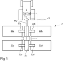
Fig 1 schematically illustrates an agricultural implement with a tractor vehicle. -
Fig 2 schematically shows a manifold module according to a first embodiment. -
Fig 3 schematically shows a manifold module according to a second embodiment. -
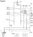
Fig 4a schematically shows a manifold module with an override module. -
Figs 4b-4c schematically show alternative override modules. -
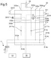
Fig 5 schematically shows a manifold module with a first type of pressure control module. -
Fig 6a schematically shows a manifold module with a second type of pressure control module. -
Fig 6b schematically shows an additional type of pressure control module. -
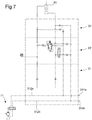
Fig 7 schematically shows a manifold module with a pressure control module and an override module. -
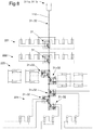
Fig 8 schematically shows a hydraulic system for an agricultural implement, which comprises a plurality of manifold modules and variants with bypass and/or pressure control. -
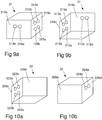
Figs 9a-9b schematically show abase module 31. -
Figs 10a-10b schematically show anoverride module 32. -
Figs 11a-11b schematically show apressure control module 33. -
Fig 1 shows an agricultural combination comprising atractor vehicle 1, such as a tractor, and an agricultural implement 2, such as a harrow, a cultivator, a plough, a seed drill, or a precision seed drill. The agricultural implement has aframe 21 and a plurality ofparts frame 21 is adjustable usinghydraulic actuators - The agricultural implement hydraulic system is fed by hydraulic power from the
tractor vehicle 1, via itshydraulic outputs 11, comprising at least one double-acting hydraulic output, i.e. a hydraulic output, the channels of which can switch between being a feed channel and a return channel depending on the operator's selection via ahydraulic control 12 in thetractor vehicle 1. - Feeding from the
tractor vehicle 1 leads to amanifold system 3 comprising a plurality of numerically controlled valves which distribute hydraulic power to thevarious actuators user interface 13, which can be located in the tractor vehicle, or can be carried by the operator. - The
manifold system 3 shown herein can be built up of a few different modules comprising abase module 31, 31' (Figs 2, 3 ), an override module (Figs 4a, 4b ) and a pressure control module (Figs 5, 6 ). A plurality ofbase modules 31, 31' can be interconnected to form a hydraulic forwarding line. Each base module can control a function, alone or together with anoverride module 32 and/or apressure control module 33, 33'. - Alternative embodiments of a base module will be described below. A function of the base module is to position-control an implement toward a desirable value, i.e. a desired position, and, when the base module valve arrangement is passive, to prevent the tool from moving from the set position.
- With reference to
Fig 2 , the base module comprises acasing 310,main channels controllable channels outgoing channels bypass channels main channel 312a is fixedly connected to thefirst bypass channel 315a and to thefirst forwarding channel 314a. The secondmain channel 312b is fixedly connected to thesecond bypass channel 315b and to thesecond forwarding channel 314b. - The
base module 31 further comprises a numerically controllable valve arrangement, which, as shown inFig 2 , comprises afirst valve 317a, which is connected to the firstmain channel 312a, and asecond valve 317b, which is connected to the firstmain channel 312a. - The
valves - The control can be provided directly from a
unit 13 in the tractor vehicle, or via aseparate control unit 35, which can be arranged on the agricultural implement 2 and have the ability to communicate using theuser interface 13, either wired or wirelessly (Wi-Fi, Bluetooth, etc.), and to control the hydraulic valves by providing a suitable signal. - The
first valve 317a is operable for retracting theactuator 23 and permits, in an activated state, feeding from the firstmain channel 312a to the firstcontrollable channel 313a and returning from the second controlledchannel 313b to the secondmain channel 312b via thereturn channel 316 by opening thecheck valve 3172a. Thecheck valve 3172a is pilot-controlled based on pressure in the channel between thevalve 317a and thecheck valve 3171a. - In an inactive state, the
valve 317a blocks feeding from the firstmain channel 312a. - In the example shown in
Fig 2 , retraction of thehydraulic actuator 23 is provided by feeding via thefirst valve 317a. - The
second valve 317b permits, in an activated state, feeding from the firstmain channel 312a to the secondcontrollable channel 313b and returning from the firstcontrollable channel 313a to the secondmain channel 312b via thereturn channel 316 by opening thecheck valve 3172b. Thecheck valve 3172b is pilot-controlled based on pressure in the channel between thevalve 317b and thecheck valve 3171b. - In the example shown in
Fig 2 , expansion of thehydraulic actuator 23 is provided by feeding via thefirst valve 317a. - The
check valves - The check valve 3161 (selectable) can prevent the pressure in the second
main channel 312b affecting thecontrollable channels - With reference to
Figs 9a-9b , thebase module 31 can be formed as a body having a first pair ofparallel sides third side 319c forming an interface for the function to be controlled, directly or via anoverride module 32 and/or apressure control module 33, 33'. Thethird side 319c can be perpendicular to the firstparallel sides - A
first side 319a can form an interface, either to an incoming channel, in which event a channel inlet can be provided with a coupling device, or to a special inlet module (not shown), or to asecond side 319b of an adjacent base unit. - Therefore, the
second side 319b can typically form an interface to afirst side 319a of the adjacent base unit. Alternatively, theports - A gasket can be arranged between
adjacent sides -
Adjacent base modules 31, 31' can be fitted to each other by e.g. a threaded joint. - The
third side 319c forms an interface to the function(s) to be controlled. - The body can be formed by a block of material, e.g. metal or polymer, or by several blocks being joined together.
- Inside the body, channels and spaces for valve assemblies and connections thereto can be formed by milling out/drilling from a piece of material and/or by casting two or more parts, which are joined together, possibly with an intermediate gasket.
- Ports can be formed as threaded holes in which a nipple for a hose connected can be fitted. Around the holes, a circumferential recess can be provided, in which a seal, such as an O-ring, can be arranged.
- Modules can be fitted together using a through-screw, which can engage with threaded holes in the adjacent module, or a nut.
- Furthermore, one of the sides can be provided with an interface for controlling a valve arrangement arranged in the base module.
- Therefore, in a normal state of feeding, i.e. where the
first channel 312a is a feed channel and thesecond channel 312b is a return channel, thevalves actuator 23. - During a reversed state of feeding, i.e. where the
first channel 312a is a return channel and thesecond channel 312b is a feed channel, thecheck valve 3161 prevents feeding. -
Fig 3 shows a base module 31', which provides the same function as the base module inFig 2 , but there, instead of fixed restrictors, check valves and pilot locks for controlling the return flow via 316, aslide valve 318 is used to permit a return flow to a tank and to ensure that the pilot lock locks. - The
slide valve 318 provides the same function as the valve arrangement inFig 2 :
When theslide valve 318 is in its intermediate position, the remaining pilot pressure is drained into thesecond channel 312b. - If the
valve 318 is projected to the left (as illustrated) feeding is provided from thefirst channel 312a to the firstcontrollable channel 313a and returning from the secondcontrollable channel 313b to thesecond channel 312b. - In this position, the
pilot valve 3171b will open as a result of the channel being pressurized between theslide valve 318 and thepilot valve 3171a. - With the
valve 318 in the right position (as illustrated) feeding is provided from thefirst channel 312a to the secondcontrollable channel 313b and returning from the firstcontrollable channel 313a to thesecond channel 312b. - In this position, the
pilot valve 3171a will open as a result of the channel being pressurized between theslide valve 318 and thepilot valve 3171b. -
Fig 4a shows schematically anoverride module 32, which is engaged with abase module 31 and anactuator 23. - The
override module 32 comprises a pair of incoming controlledconnections controllable connections override module 32 has a pair ofbypass connections bypass connections - During a normal state of feeding, i.e. with the
first channel 312a as the feed channel and thesecond channel 312b as the return channel, in principle, the override module has no effect on theactuator 23. - The
check valve 326 prevents a flow from the firstmain channel 312a, which is the feed channel. Thecheck valve 325b prevents a flow from the secondoutgoing connection 324b from affecting the secondmain channel 312b. - The
control valve 327 inhibits, in its activated position, a flow from the secondmain channel 312b. - In its passive position, the
control valve 327 permits a flow from the secondmain channel 312b to the secondoutgoing connection 324b, at the same time as thecheck valve 325a opens so that the return from theactuator 23 via the firstoutgoing connection 324a can be returned to the firstmain channel 312a. However, in the normal state of feeding, the secondmain channel 312b is the return channel, and thus thevalve 327, in its passive, open position, does not affect theactuator 23. - When the feeding from the tractor vehicle has been switched, so that the second
main channel 312b forms the feed channel and the firstmain channel 312a forms the return channel, thevalve 327 can be operated so that theactuator 23 expands whereby the base module is overridden. - It will be appreciated that the arrangement could instead be used to enable the actuator to be retracted.
- With reference to
Figs 10a-10b , theoverride module 32 can be formed as abody 321 having a first pair ofparallel sides parallel sides - A
first side 328c forms an incoming interface, for connecting to anoutgoing interface 319c of abase module 31, 31' or to anoutgoing interface 338d of apressure control module 33, 33'. - A
second side 328d forms an outgoing interface, for connecting to the actuator oractuators 23 to be controlled. - The second pair of
parallel sides parallel sides - Furthermore, one of the sides can be provided with an interface for controlling a valve arrangement arranged in the override module.
- The
override module 32 can be fitted to abase module 31, 31' or to apressure control module 33, 33' using a threaded joint, possibly with an intermediate gasket. - The override module can function as follows:
During a normal state of feeding, i.e. feeding via the firstmain channel 312a and returning via the secondmain channel 312b, it is not possible to activate the override module since thecheck valve 326 inhibits feeding from the firstmain channel 312a. - During switching of the state of feeding, so that feeding instead happens from the second
main channel 312b and returning to the firstmain channel 312a, thevalve 327 will permit feeding to theactuator 23 via thevalve 325b. Thevalve 325a is pilot-controlled by the pressure in the channel between the valve 317 and thecheck valve 325b. - Thus, the effect of this is that the actuator 23 projects as feeding now happens from the second
main channel 312b. - The
valve 327 can be used to limit the operability of theactuator 23, e.g. in order to permit a low lifting of an agricultural implement when turning on a headland. - Therefore, the
valve 327 is not necessary but can be applied if this limiting function is desired. - The
valve 327 can be controlled manually or electronically. During electronic control, this can be based on a position sensor or a feed time. - Therefore, the override module according to
Fig 4a provides operability of theactuator 23 when the feeding on themain channels base module valves -
Fig 4b shows an alternative override module, which has flexibility so that it is possible to select which of thelines second bypass channel 322b, via thevalve 327 and thecheck valve 325b to the twolines - Both of the connections have a
respective blocking device channel check valve 325b. Theblocking device blocking devices channel channels - Return connections are provided in the same way from both of the
lines first bypass channel 322a and blockingdevices - For example, by plugging the
blocking devices second channel 324b and returning from thefirst channel 324a. - As a result of plugging the blocking
devices first channel 324a and returning from thesecond channel 324b. - Such a design enables two different functions to be selectively provided using a physical prochannel.
-
Fig 4c shows an embodiment where only onebypass channel 322b is used. In this embodiment, a first check valve is arranged to permit feeding from thesecond bypass channel 322b to the secondcontrollable channel 324b when feeding has switched to feeding via thesecond channel 312b. At the same time, the pilot-controlledvalve 330b opens for returning from the firstcontrollable channel 324a to the secondcontrollable channel 324b. - In this way, more hydraulic fluid can be pushed into the second
controllable channel 324b. - One limitation is that the pressure simultaneously increases in the first
controllable channel 324a which acts as a return line. Thus the resulting force fully depends on the design of the actuator. For example, if using a slim piston rod the difference in force between the piston sides, and thus the force exerted by the actuator on its load, is less than if the piston rod is thicker. - Alternative embodiments of modules for pressure control will be described below.
-
Fig 5 shows an embodiment of apressure control module 33, for pressure controlling anactuator 23. Themodule 33 comprises amodule housing 331, which accommodates acontrol valve 3311 which is connected to thebypass channel 315a, apressure sensor 3312, apressure accumulator 3313 and acheck valve 3314. - The
pressure control valve 33 has incomingmain channels base module 31, andoutgoing feed channels actuator 23 or to anoverride module 32. - Furthermore, the
pressure control module 33 hasincoming bypass channels outgoing bypass channels - The
pressure control module 33 can also have connections, on any of the other sides, for controlling the valve, for thepressure sensor 3312 and for thepressure accumulator 3313. Alternatively, the pressure sensor can be integrated in themodule 33. - During a normal state of feeding, i.e. feeding via the
first channel 312a and returning via the secondmain channel 312b, pressure is accumulated from thefirst control channel 332a in theaccumulator 3313. By operating thecontrol valve 3311 and/or thevalve 317b, pressure can be drained from thecontrol channel 322b to the secondmain channel 312b. - During switching of the state of feeding, so that feeding instead happens from the second
main channel 312b and returning to the firstmain channel 312a, thecheck valve 3314 will inhibit feeding from the secondmain channel 312b. Thus it becomes possible to increase the pressure in thesecond control channel - Thus, in the embodiment shown, increasing the pressure in the
channel - During a normal state of feeding, the pressure in the
channel valve 317b, so that thepilot valve 3172b opens and permits draining via the valve via thereturn channel 316 to the secondmain channel 312b. - The pressure can be controlled by the
hydraulic control unit 35 via thecontrol valve 3311 and thevalves pressure sensor 3312 and a set desired value. - It will be appreciated that a pressure setting/an accumulator can be introduced on an arbitrary side of the actuator, i.e. an accumulator can act in a retracting or a projecting manner on the actuator.
- For example, a desired ground pressure can be set using a
pressure control module 33. - As described above, during a normal state of feeding, it is the
main channel 312a that is pressurized and themain channel 312b that is the return channel. - During such normal operation, the
valve 3311 prevents a flow from the firstmain channel 312a, via thecontrollable channel 313b to themain channel 312b. - When the
source 11 is reversed, thevalve 3311 can control the pressure with which theactuator 23 is fed via thebypass channels - During activation, the
valve 3311 permits a flow from thecontrollable channel 313b to themain channel 312b. -
Fig 6a shows an alternative embodiment of a pressure control module 33', which is arranged in a module housing 331'. The interface for this is the same as for thepressure control module 33, apart from that there is no connection for anaccumulator 3313. - The
valve 3311 is also identical to the embodiment according toFig 5 . - An electronic
pressure control valve 3315 is connected to bothbypass channels - A connection to the
first bypass channel 334a permits thepressure control valve 3315, during a normal state of feeding, i.e. feeding via the firstmain channel 312a and returning via the secondmain channel 312b, to supply pressure to thefirst control channel 333a when thecontrol unit 35, based on thepressure sensor 3312, determines that the pressure in thechannel 333a is too low. - In order to reduce the pressure in the
channel 333a, the pressure control valve can drain via thecheck valve 3316 to thesecond bypass channel 334b and thus to the secondmain channel 312b. - In the same way, the
valve 3311 can drain pressure from thesecond control channel 333b to thesecond bypass channel 334b. - The connection to the
second bypass channel 334b is via acheck valve 3316, which prevents feeding from thesecond bypass channel 334b when the main channels are in a reversed state of feeding. - During switching of the state of feeding, so that feeding instead happens from the second
main channel 312b and returning to the firstmain channel 312a, thecheck valves valves - Thus, a change of pressure cannot be provided in the reversed state of feeding.
- With reference to
Figs 11a-11b , thepressure control module 33, 33' can be formed as a body having a first pair ofparallel sides parallel sides first side 338c forms an incoming interface for connecting to anoutgoing interface 338c of abase module 31, 31', and of which asecond side 328d forms an outgoing interface, for connecting to the actuator oractuators 23 to be controlled, or for connecting to anoverride module 32. - The
first side 338c can have connections for incomingmain channels incoming bypass channels third side 319c of a base module. - The
second side 338d can have connections foroutgoing feed channels outgoing bypass channels - The second pair of
parallel sides parallel sides - Furthermore, one of the sides can be provided with an interface for controlling a valve arrangement arranged in the pressure control module.
-
Fig 6b shows a further alternative embodiment of apressure control module 33", which is arranged in amodule housing 331". - The pressure control module shown in
Fig 6b substantially corresponds to the pressure control module shown inFig 6a , but it is formed so that pressure control on the firstcontrollable channel 333a can be provided irrespective of which of thechannels - The
valve 3311 therefore connects bothbypass channels respective check valves valve 3311 is activated, it permits returning to the channel of thechannels - The
valve 3315 is, via one of its inputs, connected to bothbypass channels respective check valves channels - Via its second input, the
valve 3315 is connected to both channels viarespective check valves valve 3315 from the channel of thechannels - In one of its positions, the
valve 33151 permits feeding from thevalve 3315 to the firstcontrollable channel 333a, and in its second position, it permits returning from the firstcontrollable channel 333a to thevalve 3315. - By using such a pressure control module, it is possible to combine pressure control with overriding on condition that pressure control can be maintained even when lifting, for example, of a part of an implement is provided.
- In the following embodiment, with reference to
Fig 7 , an example is shown of how a combination of thebase module 31, theoverride module 32 and the pressure control module 33' can be used to control a function, here a low lifting function, in an agricultural implement 2. For details with respect to respective modules which form a part of the system, seeFigs 3 ,4 and6 . - Starting from the normal state of feeding, i.e. feeding via the first
main channel 312a and returning via the secondmain channel 312b, a ground pressure provided by theactuator 23 can be set using the pressure control module 33', which, accordingly, takes feeding from thefirst bypass channel first control channel 331a, 333a and draining to thesecond bypass channel first control channel 331a, 333a. - Before turning on a headland, the operator switches the state of feeding to a reversed state of feeding, so that feeding instead happens from the second
main channel 312b and returning to the firstmain channel 312a. Here, thesecond bypass channel valve 327 is open, thesecond control channel 324b will be pressurized, whereby the agricultural implement 2 is raised. Draining is carried out via thepilot valve 325a and thecheck valve 326 to thefirst bypass channel main channel 312a. - When the
control unit 35 determines that sufficient raising is provided, for example "low lifting", i.e. raising so that the implement is only just out of the ground, thecontrol unit 35 activates thevalve 327 so that this shuts off and stops the feeding from thesecond bypass channel - When the turning has been carried out, the operator switches back to the normal state of feeding and activates the
base module valve 317a, wherein thepilot valve 3172a opens, so that thesecond control channel 324b is drained via thechannel 316 to the secondmain channel 312b. -
Fig 8 shows an example of how modules according to the descriptions above can be assembled to form a hydraulic system of an agricultural implement. The example shows the hydraulic system without coupling to a tractor vehicle. - The hydraulic system also comprises a main coupling 111 for engagement to the
hydraulic output 11 of the tractor vehicle. Amain channel 112 emanates from the main coupling and supplies a number ofbase modules 31 which form a part of the system, where eachbase module 31 is separately controllable for controlling a function. - In the example shown, the agricultural implement has four different
controllable functions pre-tool function 221, a levelling-out function 222, tool-equippedside sections 223 and a raising and loweringfunction 224, such as a wheel or roller assembly. - The
pre-tool function 221 is shown here as a position-controllable function and its hydraulic actuators are thus controllable via abase module 31 or 31'. - In the same way, the levelling-
out function 222 is position-controllable and its hydraulic actuators are thus controllable via abase module 31 or 31'. - The
side sections 223 are separately controllable with respect to pressure and/or position, and can thus be controlled using abase module 31 or 31' each (which can control the respective relative position of the side sections in relation to a main frame of the agricultural implement), which can selectively be connected to apressure control module 33, 33' which, therefore, can control so that the respective side frame section provides a predetermined pressure on the ground. - It will be appreciated that the base module function, instead of providing position-control, can be modified to provide pressure control.
- The raising and lowering
function 224 can comprise one ormore base modules 31, 31' and onerespective override module 32. Thus the setting of a certain work depth is enabled via thebase module 31, 31' position-control function and, by switching the channels of thehydraulic output 11, an opportunity to bypass thebase module 31, 31' is enabled for quick raising of the implement before, for example, a headland. By switching the channels back, after turning, position-control can be resumed.
Claims (12)
- Agricultural implement (2) comprising a system comprising a manifold base module (31, 31'), and a first manifold sub-module (32), arranged for controlling at least one hydraulic function of the agricultural implement
wherein the manifold base module comprises:first and second feed ports (311a, 311b),a first main channel (312a), which is connected to the first feed port (311a),a second main channel (312b), which is connected to the second feed port (311b),a first numerically controllable valve arrangement (317a, 317b, 3171a, 3171b, 3172a, 3172b; 318), which is connected to the two main channels (312a, 312b),a first control channel (313a), which is controllably connectable to the main channels (312a, 312b) via the valve arrangement (317a, 317b, 3171a, 3171b, 3172a, 3172b; 318),a second control channel (313b), which is controllably connectable to the main channels (312a, 312b) via the valve arrangement (317a, 317b, 3171a, 3171b, 3172a, 3172b; 318),a first forwarding port (314a), which is connected to the first main channel (312a),a second forwarding port (314b), which is connected to the second main channel (312b), andat least one bypass channel (315a, 315b), which is connected to one of said first and second main channels (312a, 312b), for bypassing the first numerically controllable valve arrangement,wherein the feed ports (311a, 311b) provide a first coupling interface, which is formed on a first surface of the manifold module, andwherein control ports connected to the control channels (313a, 313b) provide a second coupling interface, which is separate from the first coupling interface, by being formed on a second surface of the manifold module,wherein the first manifold sub-module comprises:first and second throughgoing control channels (323a, 323b; 332a, 332b),a second numerically controllable valve arrangement (325a, 325b, 326, 327), which is arranged to control a flow between one of the control channels (323a, 323b; 324a, 324b) and the bypass channel (322a, 322b; 334a, 334b), andat least one bypass channel (322a, 322b; 334a, 334b), for bypassing the second numerically controllable valve arrangement,wherein ports connected to the control channels (324a, 324b) of the first manifold sub-module and ports connected to the bypass channels (322a, 322b) of the first manifold sub-module form a fourth coupling interface (328c), which, is formed on a first surface of the manifold sub-module, andwherein the first manifold sub-module is connected to the manifold base module by the second coupling interface being connected to the fourth coupling interface. - Agricultural implement according to Claim 1, wherein the first numerically controllable valve arrangement (317a, 317b, 3171a, 3171b, 3172a, 3172b; 318) is designed, in a first working position, to permit a flow from the first main channel (312a) to the first control channel (313a), and to permit a return flow from the second control channel (313b) to the second main channel (312b).
- Agricultural implement according to either Claim 1 or 2, wherein the first numerically controllable valve arrangement (317a, 317b, 3171a, 3171b, 3172a, 3172b; 318) is designed, in a second working position, to permit a flow from the first main channel (312a) to the second control channel (313b), and to permit a return flow from the first control channel (313a) to the second main channel (312b).
- Agricultural implement according to any one of the preceding claims, wherein the first numerically controllable valve arrangement (317a, 317b, 3171a, 3171b, 3172a, 3172b; 318) is designed, in a third working position, to prevent a flow from the first main channel (312a) to the control channels (313a, 313b).
- Agricultural implement according to any one of the preceding claims, wherein the base module comprises:a first bypass channel (315a), which is connected to the first main channel (312a), anda second bypass channel (315b), which is connected to the second main channel (312b).
- Agricultural implement according to any one of the preceding Claims, wherein the manifold sub-module comprises a first bypass channel (322a, 334a) and a second bypass channel (322b, 334b).
- Agricultural implement according to Claim 6, wherein the second numerically controllable valve arrangement is configured, in a first feeding direction of the bypass channels, to prevent feeding between the bypass channels and the control channels, and, in a second feeding direction of the bypass channels, to permit feeding between the bypass channels and the control channels.
- Agricultural implement according to Claim 6, wherein the second numerically controllable valve arrangement is configured to permit feeding to one of the control channels irrespective of the feeding direction of the bypass channels.
- Agricultural implement according to any one of Claims 6-8, wherein the second numerically controllable valve arrangement (325a, 325b, 326, 327) is adjustable between two states,
wherein the second numerically controllable valve arrangement (325a, 325b, 326, 327), in a first state, prevents a flow from the first bypass channel (322a) to the first control channel (324a), prevents a flow from the second control channel (324b) to the second bypass channel (322b) and permits a flow from the second bypass channel (334b) to the second control channel (324b), and
wherein the second numerically controllable valve arrangement (325a, 325b, 326, 327), in a second state, permits a flow from the second bypass channel (322b) to the second control channel (324b) and permits a flow from the first control channel (324a) to the first bypass channel (322a). - Agricultural implement according to any one of Claims 6-9,
wherein the second numerically controllable valve arrangement comprises:a control valve (327), which in a first state permits a flow from the second bypass channel to the second control channel (324b), and which, in a second state, prevents a flow from the second bypass channel (322b) to the second control channel (324b),a check valve (325b), which only permits a flow from the second bypass channel (322b) to the second control channel (324b),a pilot valve (325a), which only permits a flow from the first control channel (324a) to the first bypass channel (322a) when pressure is in the forward direction of the check valve (325b). - Agricultural implement according to any one of the preceding Claims,
wherein the second numerically controllable valve arrangement can be changed between two states,
wherein the second numerically controllable valve arrangement, in a first state, prevents a flow from one of the control channels to the bypass channel, and
wherein the second numerically controllable valve arrangement, in a second state, permits a flow from said control channel to the bypass channel,
wherein the second numerically controllable valve arrangement comprises a pressure control arrangement, configured to maintain a predetermined pressure in one of the control channels. - Agricultural combination comprising a tractor vehicle (1) and an agricultural implement (2) according to any one of the preceding Claims,
wherein the tractor vehicle has a double-acting hydraulic output comprising the first and second hydraulic ports,
wherein, in a first state of feeding, the first hydraulic port forms the feed channel and the second hydraulic port forms the return channel, and, in a second state of feeding, the first hydraulic port forms the return channel and the second hydraulic port forms the feed channel, and
wherein said hydraulic ports are connected to respective feed ports (311a,311b).
Priority Applications (1)
| Application Number | Priority Date | Filing Date | Title |
|---|---|---|---|
| PL18749889T PL3644704T3 (en) | 2017-06-26 | 2018-06-19 | Manifold modules. system and agricultural implement comprising such manifold modules |
Applications Claiming Priority (2)
| Application Number | Priority Date | Filing Date | Title |
|---|---|---|---|
| SE1750820A SE542189C2 (en) | 2017-06-26 | 2017-06-26 | Systems and use of systems for controlling an actuator in an agricultural implement |
| PCT/SE2018/050649 WO2019004900A1 (en) | 2017-06-26 | 2018-06-19 | Manifold modules. system and agricultural implement comprising such manifold modules |
Publications (2)
| Publication Number | Publication Date |
|---|---|
| EP3644704A1 EP3644704A1 (en) | 2020-05-06 |
| EP3644704B1 true EP3644704B1 (en) | 2020-09-30 |
Family
ID=63103985
Family Applications (1)
| Application Number | Title | Priority Date | Filing Date |
|---|---|---|---|
| EP18749889.4A Active EP3644704B1 (en) | 2017-06-26 | 2018-06-19 | Manifold modules. system and agricultural implement comprising such manifold modules |
Country Status (4)
| Country | Link |
|---|---|
| EP (1) | EP3644704B1 (en) |
| PL (1) | PL3644704T3 (en) |
| SE (1) | SE542189C2 (en) |
| WO (1) | WO2019004900A1 (en) |
Families Citing this family (1)
| Publication number | Priority date | Publication date | Assignee | Title |
|---|---|---|---|---|
| US20250255208A1 (en) * | 2024-02-09 | 2025-08-14 | Great Plains Manufacturing, Inc. | Endwise transportable implement with sequential hydraulic circuit |
Family Cites Families (6)
| Publication number | Priority date | Publication date | Assignee | Title |
|---|---|---|---|---|
| US6000315A (en) * | 1998-05-04 | 1999-12-14 | Deere & Company | Lift control for implement frame |
| US6216795B1 (en) * | 1999-07-01 | 2001-04-17 | Andrew F. Buchl | Ultrasonic transducer based device positioning system and method |
| US6698523B2 (en) * | 2002-07-02 | 2004-03-02 | Husco International, Inc. | Electrohydraulic control system for implement lift cylinders |
| FR2956462B1 (en) * | 2010-02-18 | 2012-05-18 | Poclain Hydraulics Ind | HYDRAULIC TRANSMISSION DEVICE IN WHICH THE MAIN PUMP CAN BE ACTUATED PERMANENTLY. |
| US8573111B2 (en) * | 2010-04-19 | 2013-11-05 | Deere & Company | Active implement down force system with automatic latching of tractor power beyond pressure |
| US9458604B2 (en) * | 2014-01-03 | 2016-10-04 | Caterpillar Inc. | Hybrid apparatus and method for hydraulic systems |
-
2017
- 2017-06-26 SE SE1750820A patent/SE542189C2/en unknown
-
2018
- 2018-06-19 WO PCT/SE2018/050649 patent/WO2019004900A1/en not_active Ceased
- 2018-06-19 EP EP18749889.4A patent/EP3644704B1/en active Active
- 2018-06-19 PL PL18749889T patent/PL3644704T3/en unknown
Non-Patent Citations (1)
| Title |
|---|
| None * |
Also Published As
| Publication number | Publication date |
|---|---|
| EP3644704A1 (en) | 2020-05-06 |
| PL3644704T3 (en) | 2021-04-06 |
| SE542189C2 (en) | 2020-03-10 |
| WO2019004900A1 (en) | 2019-01-03 |
| SE1750820A1 (en) | 2018-12-27 |
Similar Documents
| Publication | Publication Date | Title |
|---|---|---|
| US8464758B2 (en) | Valve system | |
| US8573111B2 (en) | Active implement down force system with automatic latching of tractor power beyond pressure | |
| RU2653081C2 (en) | Agricultural implement with electro-hydraulic cylinders | |
| US9003951B2 (en) | Hydraulic system with bi-directional regeneration | |
| US8056465B2 (en) | Active implement down force system providing reduced heat generation | |
| US4825655A (en) | Master/slave hydraulic system with rebound compensation | |
| CN101166904A (en) | Hydraulic system with pressure compensator | |
| US6354081B1 (en) | Attachment for skid steer loader or other commercial work vehicle having wireless hydraulic sequencing block | |
| US8516944B2 (en) | Valve arrangement having individual pressure scale and load-lowering valve | |
| CN103154382B (en) | connection configuration | |
| US3438307A (en) | Differential piston control system | |
| EP3309407A1 (en) | Hydraulic systems for construction machinery | |
| EP3284953B1 (en) | Fluid pressure control device | |
| WO2019004900A1 (en) | Manifold modules. system and agricultural implement comprising such manifold modules | |
| US6029559A (en) | Telescoping system with multiple single-stage telescopic cylinders | |
| US20120152368A1 (en) | Independent Metering Valve with Flow Limiter | |
| EP3094901A1 (en) | Hydraulic valve body and hydraulic valve | |
| EP0836678B1 (en) | Hydraulic valve to maintain control in fluid-loss condition | |
| CA3160823A1 (en) | Fluid flushing system for a hydraulic circuit of a work machine | |
| KR102707689B1 (en) | Working machine lifting and working fluid take out hydraulic device of agricultural work vehicle | |
| US20230354733A1 (en) | Hydraulic adjustment device | |
| EP4063668B1 (en) | System to reduce line loss in pressure control hydraulic circuit | |
| US20200045870A1 (en) | Depth Control System For Raising And Lowering A Work Unit Of An Implement | |
| EP2933501B1 (en) | Hydraulic circuit for construction machine | |
| JPH10169607A (en) | Fluid cylinder control device and method |
Legal Events
| Date | Code | Title | Description |
|---|---|---|---|
| STAA | Information on the status of an ep patent application or granted ep patent |
Free format text: STATUS: UNKNOWN |
|
| STAA | Information on the status of an ep patent application or granted ep patent |
Free format text: STATUS: THE INTERNATIONAL PUBLICATION HAS BEEN MADE |
|
| PUAI | Public reference made under article 153(3) epc to a published international application that has entered the european phase |
Free format text: ORIGINAL CODE: 0009012 |
|
| STAA | Information on the status of an ep patent application or granted ep patent |
Free format text: STATUS: REQUEST FOR EXAMINATION WAS MADE |
|
| 17P | Request for examination filed |
Effective date: 20191219 |
|
| AK | Designated contracting states |
Kind code of ref document: A1 Designated state(s): AL AT BE BG CH CY CZ DE DK EE ES FI FR GB GR HR HU IE IS IT LI LT LU LV MC MK MT NL NO PL PT RO RS SE SI SK SM TR |
|
| AX | Request for extension of the european patent |
Extension state: BA ME |
|
| GRAP | Despatch of communication of intention to grant a patent |
Free format text: ORIGINAL CODE: EPIDOSNIGR1 |
|
| STAA | Information on the status of an ep patent application or granted ep patent |
Free format text: STATUS: GRANT OF PATENT IS INTENDED |
|
| INTG | Intention to grant announced |
Effective date: 20200507 |
|
| GRAS | Grant fee paid |
Free format text: ORIGINAL CODE: EPIDOSNIGR3 |
|
| GRAA | (expected) grant |
Free format text: ORIGINAL CODE: 0009210 |
|
| STAA | Information on the status of an ep patent application or granted ep patent |
Free format text: STATUS: THE PATENT HAS BEEN GRANTED |
|
| AK | Designated contracting states |
Kind code of ref document: B1 Designated state(s): AL AT BE BG CH CY CZ DE DK EE ES FI FR GB GR HR HU IE IS IT LI LT LU LV MC MK MT NL NO PL PT RO RS SE SI SK SM TR |
|
| DAV | Request for validation of the european patent (deleted) | ||
| DAX | Request for extension of the european patent (deleted) | ||
| REG | Reference to a national code |
Ref country code: CH Ref legal event code: EP Ref country code: GB Ref legal event code: FG4D |
|
| REG | Reference to a national code |
Ref country code: AT Ref legal event code: REF Ref document number: 1317784 Country of ref document: AT Kind code of ref document: T Effective date: 20201015 |
|
| REG | Reference to a national code |
Ref country code: DE Ref legal event code: R096 Ref document number: 602018008330 Country of ref document: DE |
|
| REG | Reference to a national code |
Ref country code: IE Ref legal event code: FG4D |
|
| PG25 | Lapsed in a contracting state [announced via postgrant information from national office to epo] |
Ref country code: HR Free format text: LAPSE BECAUSE OF FAILURE TO SUBMIT A TRANSLATION OF THE DESCRIPTION OR TO PAY THE FEE WITHIN THE PRESCRIBED TIME-LIMIT Effective date: 20200930 Ref country code: GR Free format text: LAPSE BECAUSE OF FAILURE TO SUBMIT A TRANSLATION OF THE DESCRIPTION OR TO PAY THE FEE WITHIN THE PRESCRIBED TIME-LIMIT Effective date: 20201231 Ref country code: NO Free format text: LAPSE BECAUSE OF FAILURE TO SUBMIT A TRANSLATION OF THE DESCRIPTION OR TO PAY THE FEE WITHIN THE PRESCRIBED TIME-LIMIT Effective date: 20201230 Ref country code: SE Free format text: LAPSE BECAUSE OF FAILURE TO SUBMIT A TRANSLATION OF THE DESCRIPTION OR TO PAY THE FEE WITHIN THE PRESCRIBED TIME-LIMIT Effective date: 20200930 Ref country code: FI Free format text: LAPSE BECAUSE OF FAILURE TO SUBMIT A TRANSLATION OF THE DESCRIPTION OR TO PAY THE FEE WITHIN THE PRESCRIBED TIME-LIMIT Effective date: 20200930 Ref country code: BG Free format text: LAPSE BECAUSE OF FAILURE TO SUBMIT A TRANSLATION OF THE DESCRIPTION OR TO PAY THE FEE WITHIN THE PRESCRIBED TIME-LIMIT Effective date: 20201230 |
|
| REG | Reference to a national code |
Ref country code: AT Ref legal event code: MK05 Ref document number: 1317784 Country of ref document: AT Kind code of ref document: T Effective date: 20200930 |
|
| PG25 | Lapsed in a contracting state [announced via postgrant information from national office to epo] |
Ref country code: LV Free format text: LAPSE BECAUSE OF FAILURE TO SUBMIT A TRANSLATION OF THE DESCRIPTION OR TO PAY THE FEE WITHIN THE PRESCRIBED TIME-LIMIT Effective date: 20200930 Ref country code: RS Free format text: LAPSE BECAUSE OF FAILURE TO SUBMIT A TRANSLATION OF THE DESCRIPTION OR TO PAY THE FEE WITHIN THE PRESCRIBED TIME-LIMIT Effective date: 20200930 |
|
| REG | Reference to a national code |
Ref country code: NL Ref legal event code: MP Effective date: 20200930 |
|
| REG | Reference to a national code |
Ref country code: LT Ref legal event code: MG4D |
|
| PG25 | Lapsed in a contracting state [announced via postgrant information from national office to epo] |
Ref country code: EE Free format text: LAPSE BECAUSE OF FAILURE TO SUBMIT A TRANSLATION OF THE DESCRIPTION OR TO PAY THE FEE WITHIN THE PRESCRIBED TIME-LIMIT Effective date: 20200930 Ref country code: RO Free format text: LAPSE BECAUSE OF FAILURE TO SUBMIT A TRANSLATION OF THE DESCRIPTION OR TO PAY THE FEE WITHIN THE PRESCRIBED TIME-LIMIT Effective date: 20200930 Ref country code: PT Free format text: LAPSE BECAUSE OF FAILURE TO SUBMIT A TRANSLATION OF THE DESCRIPTION OR TO PAY THE FEE WITHIN THE PRESCRIBED TIME-LIMIT Effective date: 20210201 Ref country code: LT Free format text: LAPSE BECAUSE OF FAILURE TO SUBMIT A TRANSLATION OF THE DESCRIPTION OR TO PAY THE FEE WITHIN THE PRESCRIBED TIME-LIMIT Effective date: 20200930 Ref country code: SM Free format text: LAPSE BECAUSE OF FAILURE TO SUBMIT A TRANSLATION OF THE DESCRIPTION OR TO PAY THE FEE WITHIN THE PRESCRIBED TIME-LIMIT Effective date: 20200930 |
|
| PG25 | Lapsed in a contracting state [announced via postgrant information from national office to epo] |
Ref country code: IS Free format text: LAPSE BECAUSE OF FAILURE TO SUBMIT A TRANSLATION OF THE DESCRIPTION OR TO PAY THE FEE WITHIN THE PRESCRIBED TIME-LIMIT Effective date: 20210130 Ref country code: AT Free format text: LAPSE BECAUSE OF FAILURE TO SUBMIT A TRANSLATION OF THE DESCRIPTION OR TO PAY THE FEE WITHIN THE PRESCRIBED TIME-LIMIT Effective date: 20200930 Ref country code: AL Free format text: LAPSE BECAUSE OF FAILURE TO SUBMIT A TRANSLATION OF THE DESCRIPTION OR TO PAY THE FEE WITHIN THE PRESCRIBED TIME-LIMIT Effective date: 20200930 Ref country code: ES Free format text: LAPSE BECAUSE OF FAILURE TO SUBMIT A TRANSLATION OF THE DESCRIPTION OR TO PAY THE FEE WITHIN THE PRESCRIBED TIME-LIMIT Effective date: 20200930 |
|
| PG25 | Lapsed in a contracting state [announced via postgrant information from national office to epo] |
Ref country code: NL Free format text: LAPSE BECAUSE OF FAILURE TO SUBMIT A TRANSLATION OF THE DESCRIPTION OR TO PAY THE FEE WITHIN THE PRESCRIBED TIME-LIMIT Effective date: 20200930 Ref country code: SK Free format text: LAPSE BECAUSE OF FAILURE TO SUBMIT A TRANSLATION OF THE DESCRIPTION OR TO PAY THE FEE WITHIN THE PRESCRIBED TIME-LIMIT Effective date: 20200930 |
|
| REG | Reference to a national code |
Ref country code: DE Ref legal event code: R097 Ref document number: 602018008330 Country of ref document: DE |
|
| PLBE | No opposition filed within time limit |
Free format text: ORIGINAL CODE: 0009261 |
|
| STAA | Information on the status of an ep patent application or granted ep patent |
Free format text: STATUS: NO OPPOSITION FILED WITHIN TIME LIMIT |
|
| PG25 | Lapsed in a contracting state [announced via postgrant information from national office to epo] |
Ref country code: DK Free format text: LAPSE BECAUSE OF FAILURE TO SUBMIT A TRANSLATION OF THE DESCRIPTION OR TO PAY THE FEE WITHIN THE PRESCRIBED TIME-LIMIT Effective date: 20200930 |
|
| 26N | No opposition filed |
Effective date: 20210701 |
|
| PG25 | Lapsed in a contracting state [announced via postgrant information from national office to epo] |
Ref country code: IT Free format text: LAPSE BECAUSE OF FAILURE TO SUBMIT A TRANSLATION OF THE DESCRIPTION OR TO PAY THE FEE WITHIN THE PRESCRIBED TIME-LIMIT Effective date: 20200930 |
|
| PG25 | Lapsed in a contracting state [announced via postgrant information from national office to epo] |
Ref country code: SI Free format text: LAPSE BECAUSE OF FAILURE TO SUBMIT A TRANSLATION OF THE DESCRIPTION OR TO PAY THE FEE WITHIN THE PRESCRIBED TIME-LIMIT Effective date: 20200930 |
|
| PG25 | Lapsed in a contracting state [announced via postgrant information from national office to epo] |
Ref country code: MC Free format text: LAPSE BECAUSE OF FAILURE TO SUBMIT A TRANSLATION OF THE DESCRIPTION OR TO PAY THE FEE WITHIN THE PRESCRIBED TIME-LIMIT Effective date: 20200930 |
|
| REG | Reference to a national code |
Ref country code: CH Ref legal event code: PL |
|
| REG | Reference to a national code |
Ref country code: BE Ref legal event code: MM Effective date: 20210630 |
|
| PG25 | Lapsed in a contracting state [announced via postgrant information from national office to epo] |
Ref country code: LU Free format text: LAPSE BECAUSE OF NON-PAYMENT OF DUE FEES Effective date: 20210619 |
|
| PG25 | Lapsed in a contracting state [announced via postgrant information from national office to epo] |
Ref country code: LI Free format text: LAPSE BECAUSE OF NON-PAYMENT OF DUE FEES Effective date: 20210630 Ref country code: IE Free format text: LAPSE BECAUSE OF NON-PAYMENT OF DUE FEES Effective date: 20210619 Ref country code: CH Free format text: LAPSE BECAUSE OF NON-PAYMENT OF DUE FEES Effective date: 20210630 |
|
| PG25 | Lapsed in a contracting state [announced via postgrant information from national office to epo] |
Ref country code: IS Free format text: LAPSE BECAUSE OF FAILURE TO SUBMIT A TRANSLATION OF THE DESCRIPTION OR TO PAY THE FEE WITHIN THE PRESCRIBED TIME-LIMIT Effective date: 20210130 |
|
| PG25 | Lapsed in a contracting state [announced via postgrant information from national office to epo] |
Ref country code: BE Free format text: LAPSE BECAUSE OF NON-PAYMENT OF DUE FEES Effective date: 20210630 |
|
| P01 | Opt-out of the competence of the unified patent court (upc) registered |
Effective date: 20230523 |
|
| PG25 | Lapsed in a contracting state [announced via postgrant information from national office to epo] |
Ref country code: CY Free format text: LAPSE BECAUSE OF FAILURE TO SUBMIT A TRANSLATION OF THE DESCRIPTION OR TO PAY THE FEE WITHIN THE PRESCRIBED TIME-LIMIT Effective date: 20200930 |
|
| PG25 | Lapsed in a contracting state [announced via postgrant information from national office to epo] |
Ref country code: HU Free format text: LAPSE BECAUSE OF FAILURE TO SUBMIT A TRANSLATION OF THE DESCRIPTION OR TO PAY THE FEE WITHIN THE PRESCRIBED TIME-LIMIT; INVALID AB INITIO Effective date: 20180619 |
|
| PG25 | Lapsed in a contracting state [announced via postgrant information from national office to epo] |
Ref country code: MK Free format text: LAPSE BECAUSE OF FAILURE TO SUBMIT A TRANSLATION OF THE DESCRIPTION OR TO PAY THE FEE WITHIN THE PRESCRIBED TIME-LIMIT Effective date: 20200930 |
|
| PG25 | Lapsed in a contracting state [announced via postgrant information from national office to epo] |
Ref country code: TR Free format text: LAPSE BECAUSE OF FAILURE TO SUBMIT A TRANSLATION OF THE DESCRIPTION OR TO PAY THE FEE WITHIN THE PRESCRIBED TIME-LIMIT Effective date: 20200930 |
|
| PG25 | Lapsed in a contracting state [announced via postgrant information from national office to epo] |
Ref country code: MT Free format text: LAPSE BECAUSE OF FAILURE TO SUBMIT A TRANSLATION OF THE DESCRIPTION OR TO PAY THE FEE WITHIN THE PRESCRIBED TIME-LIMIT Effective date: 20200930 |
|
| PGFP | Annual fee paid to national office [announced via postgrant information from national office to epo] |
Ref country code: PL Payment date: 20260504 Year of fee payment: 9 Ref country code: GB Payment date: 20260511 Year of fee payment: 9 |
|
| PGFP | Annual fee paid to national office [announced via postgrant information from national office to epo] |
Ref country code: DE Payment date: 20260506 Year of fee payment: 9 |
|
| PGFP | Annual fee paid to national office [announced via postgrant information from national office to epo] |
Ref country code: CZ Payment date: 20260609 Year of fee payment: 9 |
|
| PGFP | Annual fee paid to national office [announced via postgrant information from national office to epo] |
Ref country code: FR Payment date: 20260521 Year of fee payment: 9 |